EP3746828B1 - Achromatic astigmatic anamorphic objective - Google Patents
Achromatic astigmatic anamorphic objective Download PDFInfo
- Publication number
- EP3746828B1 EP3746828B1 EP19702781.6A EP19702781A EP3746828B1 EP 3746828 B1 EP3746828 B1 EP 3746828B1 EP 19702781 A EP19702781 A EP 19702781A EP 3746828 B1 EP3746828 B1 EP 3746828B1
- Authority
- EP
- European Patent Office
- Prior art keywords
- laser
- beams
- transverse direction
- working
- plane
- Prior art date
- Legal status (The legal status is an assumption and is not a legal conclusion. Google has not performed a legal analysis and makes no representation as to the accuracy of the status listed.)
- Active
Links
Images


Classifications
-
- G—PHYSICS
- G02—OPTICS
- G02B—OPTICAL ELEMENTS, SYSTEMS OR APPARATUS
- G02B13/00—Optical objectives specially designed for the purposes specified below
- G02B13/08—Anamorphotic objectives
-
- G—PHYSICS
- G01—MEASURING; TESTING
- G01N—INVESTIGATING OR ANALYSING MATERIALS BY DETERMINING THEIR CHEMICAL OR PHYSICAL PROPERTIES
- G01N15/00—Investigating characteristics of particles; Investigating permeability, pore-volume or surface-area of porous materials
- G01N15/10—Investigating individual particles
- G01N15/14—Optical investigation techniques, e.g. flow cytometry
- G01N15/1434—Optical arrangements
-
- G—PHYSICS
- G01—MEASURING; TESTING
- G01N—INVESTIGATING OR ANALYSING MATERIALS BY DETERMINING THEIR CHEMICAL OR PHYSICAL PROPERTIES
- G01N15/00—Investigating characteristics of particles; Investigating permeability, pore-volume or surface-area of porous materials
- G01N15/10—Investigating individual particles
- G01N15/14—Optical investigation techniques, e.g. flow cytometry
- G01N15/1456—Optical investigation techniques, e.g. flow cytometry without spatial resolution of the texture or inner structure of the particle, e.g. processing of pulse signals
- G01N15/1459—Optical investigation techniques, e.g. flow cytometry without spatial resolution of the texture or inner structure of the particle, e.g. processing of pulse signals the analysis being performed on a sample stream
-
- G—PHYSICS
- G02—OPTICS
- G02B—OPTICAL ELEMENTS, SYSTEMS OR APPARATUS
- G02B13/00—Optical objectives specially designed for the purposes specified below
- G02B13/14—Optical objectives specially designed for the purposes specified below for use with infrared or ultraviolet radiation
- G02B13/146—Optical objectives specially designed for the purposes specified below for use with infrared or ultraviolet radiation with corrections for use in multiple wavelength bands, such as infrared and visible light, e.g. FLIR systems
-
- G—PHYSICS
- G02—OPTICS
- G02B—OPTICAL ELEMENTS, SYSTEMS OR APPARATUS
- G02B23/00—Telescopes, e.g. binoculars; Periscopes; Instruments for viewing the inside of hollow bodies; Viewfinders; Optical aiming or sighting devices
- G02B23/02—Telescopes, e.g. binoculars; Periscopes; Instruments for viewing the inside of hollow bodies; Viewfinders; Optical aiming or sighting devices involving prisms or mirrors
- G02B23/04—Telescopes, e.g. binoculars; Periscopes; Instruments for viewing the inside of hollow bodies; Viewfinders; Optical aiming or sighting devices involving prisms or mirrors for the purpose of beam splitting or combining, e.g. fitted with eyepieces for more than one observer
-
- G—PHYSICS
- G02—OPTICS
- G02B—OPTICAL ELEMENTS, SYSTEMS OR APPARATUS
- G02B27/00—Optical systems or apparatus not provided for by any of the groups G02B1/00 - G02B26/00, G02B30/00
- G02B27/09—Beam shaping, e.g. changing the cross-sectional area, not otherwise provided for
- G02B27/0905—Dividing and/or superposing multiple light beams
-
- G—PHYSICS
- G02—OPTICS
- G02B—OPTICAL ELEMENTS, SYSTEMS OR APPARATUS
- G02B27/00—Optical systems or apparatus not provided for by any of the groups G02B1/00 - G02B26/00, G02B30/00
- G02B27/09—Beam shaping, e.g. changing the cross-sectional area, not otherwise provided for
- G02B27/0911—Anamorphotic systems
-
- G—PHYSICS
- G02—OPTICS
- G02B—OPTICAL ELEMENTS, SYSTEMS OR APPARATUS
- G02B27/00—Optical systems or apparatus not provided for by any of the groups G02B1/00 - G02B26/00, G02B30/00
- G02B27/09—Beam shaping, e.g. changing the cross-sectional area, not otherwise provided for
- G02B27/0938—Using specific optical elements
- G02B27/095—Refractive optical elements
- G02B27/0955—Lenses
- G02B27/0966—Cylindrical lenses
-
- G—PHYSICS
- G02—OPTICS
- G02B—OPTICAL ELEMENTS, SYSTEMS OR APPARATUS
- G02B27/00—Optical systems or apparatus not provided for by any of the groups G02B1/00 - G02B26/00, G02B30/00
- G02B27/10—Beam splitting or combining systems
- G02B27/1006—Beam splitting or combining systems for splitting or combining different wavelengths
-
- G—PHYSICS
- G02—OPTICS
- G02B—OPTICAL ELEMENTS, SYSTEMS OR APPARATUS
- G02B27/00—Optical systems or apparatus not provided for by any of the groups G02B1/00 - G02B26/00, G02B30/00
- G02B27/10—Beam splitting or combining systems
- G02B27/14—Beam splitting or combining systems operating by reflection only
- G02B27/141—Beam splitting or combining systems operating by reflection only using dichroic mirrors
-
- G—PHYSICS
- G02—OPTICS
- G02B—OPTICAL ELEMENTS, SYSTEMS OR APPARATUS
- G02B27/00—Optical systems or apparatus not provided for by any of the groups G02B1/00 - G02B26/00, G02B30/00
- G02B27/10—Beam splitting or combining systems
- G02B27/14—Beam splitting or combining systems operating by reflection only
- G02B27/145—Beam splitting or combining systems operating by reflection only having sequential partially reflecting surfaces
-
- G—PHYSICS
- G02—OPTICS
- G02B—OPTICAL ELEMENTS, SYSTEMS OR APPARATUS
- G02B27/00—Optical systems or apparatus not provided for by any of the groups G02B1/00 - G02B26/00, G02B30/00
- G02B27/18—Optical systems or apparatus not provided for by any of the groups G02B1/00 - G02B26/00, G02B30/00 for optical projection, e.g. combination of mirror and condenser and objective
-
- G—PHYSICS
- G02—OPTICS
- G02B—OPTICAL ELEMENTS, SYSTEMS OR APPARATUS
- G02B9/00—Optical objectives characterised both by the number of the components and their arrangements according to their sign, i.e. + or -
- G02B9/12—Optical objectives characterised both by the number of the components and their arrangements according to their sign, i.e. + or - having three components only
- G02B9/14—Optical objectives characterised both by the number of the components and their arrangements according to their sign, i.e. + or - having three components only arranged + - +
- G02B9/16—Optical objectives characterised both by the number of the components and their arrangements according to their sign, i.e. + or - having three components only arranged + - + all the components being simple
-
- A—HUMAN NECESSITIES
- A61—MEDICAL OR VETERINARY SCIENCE; HYGIENE
- A61B—DIAGNOSIS; SURGERY; IDENTIFICATION
- A61B5/00—Measuring for diagnostic purposes; Identification of persons
- A61B5/0059—Measuring for diagnostic purposes; Identification of persons using light, e.g. diagnosis by transillumination, diascopy, fluorescence
- A61B5/0071—Measuring for diagnostic purposes; Identification of persons using light, e.g. diagnosis by transillumination, diascopy, fluorescence by measuring fluorescence emission
-
- A—HUMAN NECESSITIES
- A61—MEDICAL OR VETERINARY SCIENCE; HYGIENE
- A61B—DIAGNOSIS; SURGERY; IDENTIFICATION
- A61B5/00—Measuring for diagnostic purposes; Identification of persons
- A61B5/0059—Measuring for diagnostic purposes; Identification of persons using light, e.g. diagnosis by transillumination, diascopy, fluorescence
- A61B5/0075—Measuring for diagnostic purposes; Identification of persons using light, e.g. diagnosis by transillumination, diascopy, fluorescence by spectroscopy, i.e. measuring spectra, e.g. Raman spectroscopy, infrared absorption spectroscopy
-
- G—PHYSICS
- G01—MEASURING; TESTING
- G01N—INVESTIGATING OR ANALYSING MATERIALS BY DETERMINING THEIR CHEMICAL OR PHYSICAL PROPERTIES
- G01N15/00—Investigating characteristics of particles; Investigating permeability, pore-volume or surface-area of porous materials
- G01N15/10—Investigating individual particles
- G01N2015/1006—Investigating individual particles for cytology
-
- G—PHYSICS
- G01—MEASURING; TESTING
- G01N—INVESTIGATING OR ANALYSING MATERIALS BY DETERMINING THEIR CHEMICAL OR PHYSICAL PROPERTIES
- G01N15/00—Investigating characteristics of particles; Investigating permeability, pore-volume or surface-area of porous materials
- G01N15/10—Investigating individual particles
- G01N15/14—Optical investigation techniques, e.g. flow cytometry
- G01N15/1434—Optical arrangements
- G01N2015/1452—Adjustment of focus; Alignment
Landscapes
- Physics & Mathematics (AREA)
- General Physics & Mathematics (AREA)
- Optics & Photonics (AREA)
- Chemical & Material Sciences (AREA)
- Health & Medical Sciences (AREA)
- Biochemistry (AREA)
- Life Sciences & Earth Sciences (AREA)
- Analytical Chemistry (AREA)
- Dispersion Chemistry (AREA)
- General Health & Medical Sciences (AREA)
- Immunology (AREA)
- Pathology (AREA)
- Astronomy & Astrophysics (AREA)
- Toxicology (AREA)
- Lenses (AREA)
- Laser Beam Processing (AREA)
- Color Electrophotography (AREA)
- Details Of Television Scanning (AREA)
- Luminescent Compositions (AREA)
Description
- The present invention relates in general to projection lenses. The invention relates in particular to anamorphic projection lenses for focusing two or more laser-beams having different wavelengths into a common elliptical focal-spot.
- A basic principle of flow cytometry is the passage of particles in a fluid-stream through a focused beam of laser-radiation. The particles, particularly biological cells, can be detected, identified, counted, and sorted. Cell components are fluorescently labelled and then illuminated by the laser-radiation. Scattered and emitted radiation can be measured to determine the quantity and types of cells present in a sample.
- Several detectors are carefully placed around the point where the fluid-stream passes through the focused laser-beam. The suspended particles, which may range in size from 0.2 micrometers (µm) to 150 µm, pass through the focused laser-beam and scatter the laser-radiation. The fluorescently-labelled cell components are also excited by the focused laser-beam and emit radiation (fluorescence) at a longer wavelength than that of the laser-beam. This combination of scattered and fluorescent radiation is measured by the detectors. Measurement data is then analyzed, using special software, by a computer that is attached to the flow cytometer. Thousands of particles per second can be measured and analyzed.
- It is generally accepted that the above described flow cytometry process is more flexible and more accurate when more wavelengths of laser-radiation are included in the laser-beam. In practice, this is accomplished by combining component laser-beams from different lasers along a common path to provide a combined laser-beam that is focused into the fluid-stream. Diode-laser modules are typically used for providing the component laser-beams. Commercially available diode-laser modules can provide laser-radiation at fundamental wavelengths ranging from the near ultraviolet to the near infrared.
- An increasing number and range of wavelengths presents significant problems in the design and construction of an optical objective for focusing the combined laser-beam into the fluid-stream. It is generally accepted that for focusing two significantly different wavelengths (for example, red and blue) at a common location (focal plane) a focusing objective must include at least two optical-elements having different spectral dispersion. For example, two lenses made of different materials having high and low spectral dispersion. An objective arranged to focus two different wavelengths in a common focal plane is generally referred to as an "achromatic objective".
- If three significantly different wavelengths (for example, red, green, and blue) are to be focused at a common location, a focusing objective must include at least three optical-elements having different spectral dispersion. An objective arranged to focus three significantly different wavelengths in a common focal plane is generally referred to as an "apochromatic objective".
- In achromatic or apochromatic objectives, individual optical-elements (singlets) of different spectral dispersion may need to be "cemented" together in forms referred to by practitioners of the lens design art as "doublets" or "triplets". These forms can be problematic when ultraviolet wavelengths are included in a flow cytometer, as optical cements (adhesives) may be degraded by ultraviolet laser-radiation.
- Based on conventional optical design wisdom, it is expected that the objective required to focus the laser-beam into the fluid-stream will become even more complex and more expensive as additional wavelengths of laser-radiation are included in a flow cytometer. For example, a flow cytometer having four or more wavelengths. This could result in the complexity and cost of a focusing objective imposing a practical upper limit to the number of wavelengths of laser-radiation that can be used in a flow cytometer.
- US patent application with publication number
US 2018/0017769 discloses an objective lens for use in a flow cytometer including only three singlet lens-elements for focusing an input laser-radiation beam including at least four different laser radiation wavelengths in a common plane. Two of the elements are cylindrical elements arranged as a cylindrical telescope for shaping and reducing the size of the input laser-beam. The third element is a spherical element arranged to focus the reduced size beam in the common plane. - European patent application with
publication number EP 1 403 632 discloses a prism-based cytometry excitation optics system which redirects, shapes and combines plural beams provided by light sources, so they can be focused by an objective into closely spaced spots within the channel of a cytometry flow cell. The mounted set of dispersive prisms redirects beams of different wavelengths so that beams with separated inputs emerge from the final prism, substantially overlapping in position and nearly parallel to one another. - There is need for a simple focusing objective, capable of focusing four or more laser-radiation wavelengths in a common focal plane, but wherein the number of different optical materials (glasses) required is less than the number of different wavelengths to be focused in the common focal plane. Preferably, the focusing objective should not include any cemented doublet or triplet elements. Preferably, the focusing objective will create a combined laser-beam in the common focal plane that is insensitive to any fluctuations of beam-parameters of the component laser-beams from different lasers.
- In one aspect, optical apparatus in accordance with the present disclosure comprises an illumination source arranged to deliver a plurality of collimated coaxial laser-beams. Each laser-beam has a different wavelength and a different beam-width. An anamorphic objective is provided that has first and second transverse directions orthogonal to each other. The objective is arranged to receive the laser-beams from the illumination source and to project the laser-beams towards a working-plane at a working-distance from the objective. The objective is configured and arranged such that, in the first transverse direction of the objective, the laser-beams are each focused to a beam-waist located about in the working-plane and having about the same beam-waist width. In the second transverse direction of the objective, the laser-beams are focused to beam-waists at different locations that are displaced from the working-plane. The displacements are selected such that the laser-beams have about the same beam-width in the working-plane.
- The accompanying drawings, which are incorporated in and constitute a part of the specification, schematically illustrate a preferred embodiment of the present invention, and together with the general description given above and the detailed description of the preferred embodiment given below, serve to explain principles of the present invention.
-
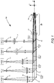
FIG. 1 is a plan-view schematically illustrating a preferred embodiment of optical apparatus in accordance with the present invention, including a plurality lasers delivering beams of radiation having a corresponding plurality of different wavelengths, a corresponding plurality of telescopes arranged to collimate and expand the respective beams to different diameters that are about proportional to the different wavelengths, a beam-combiner for coaxially combining the collimated and expanded beams, and an anamorphic focusing objective arranged to focus the beams in a working-plane of the apparatus. -
FIGs. 2A and FIG 2B are respectively a side-view and a plan-view of a preferred arrangement of the anamorphic objective ofFIG. 1 , including two cylindrical lens-elements and a rotationally-symmetric lens-element. -
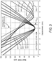
FIG. 3 is a graph schematically illustrating beam-width as a function of displacement from the working-plane in one example of the lens ofFIGS 2A and 2B , with beam-waists of all beams in a Y transverse direction located in the working-plane and having the same beam-waist width, and beam-waists in a X transverse direction located beyond the working-plane at different wavelength-dependent distances selected such that the beams have a common beam-width in the working-plane. -
FIG. 4 is a graph schematically illustrating beam-width as a function of displacement from the working-plane in another example of the lens ofFIGS 2A and 2B , with beam-waists of all beams in a Y transverse direction located in the working-plane and having the same beam-waist width, and beam-waists in a X transverse direction located closer than the working-plane at different wavelength-dependent distances selected such that the beams have a common beam-width in the working-plane. - Turning now to the drawings, wherein like features are designated by like reference numerals,
FIG. 1 is a plan-view schematically illustrating apreferred embodiment 10 of optical apparatus in accordance with the present invention.Optical apparatus 10 includes a plurality (here 5) of lasers, explicitly indicated in the drawing according to the wavelength of the laser-beam generated by each laser. The wavelengths are 355 nanometers (nm), 405 nm, 488 nm, 561 nm, and 637 nm. These wavelengths are exemplary and should not be considered limiting, but are consistent with wavelengths of commercially available diode-lasers and diode-pumped solid-state lasers. - Associated with the lasers is a corresponding plurality of telescopes (beam expanders), each thereof formed by a
negative lens 12 and apositive lens 14. The lenses in the different laser beams are designated by the same reference numeral for similarity of function, but may have different specifications, consistent with different degrees of beam-expansion. Exemplary specifications are discussed further hereinbelow. Laser-beams delivered by the telescopes are collimated and circular in cross-section. - It is understood that the term "collimated", as used in this description and the appended claims, recognizes that laser-beams are rarely precisely collimated, even when precise collimation is intended. The degree of collimation varies with distance from a collimating device due to Gaussian beam propagation effects, as is well known in the art. It is also understood that the term "circular" allows that the laser-beams may be slightly elliptical in cross-section, having major and minor axis that are the same to within a few percent, rather than being precisely circular. Herein below, the orientation and arrangement of elements and beams in
optical apparatus 10 will be discussed with reference to Cartesian X-, Y-, and Z-axes, which are depicted on the drawing. - The beam-diameters of individual laser-beams decrease in about proportion to wavelength, and are combined coaxially along the Z-axis by a turning
mirror 16 and four dichroic beam-combining mirrors 18. Herein, "beam-diameter" is used when beams are about circular in cross-section and "beam-width" is used when beams are non-circular (elliptical) in cross-section. Liketelescope lenses mirrors 18 are designated by the same reference numeral for similarity of function, but have different specifications dependent on the particular wavelengths being transmitted or reflected. Dichroic beam-combining arrangements are well known to practitioners of the art and a detailed description thereof is not necessary for understanding principles of the present invention. The lasers, the telescopes, the turning mirror, and the beam-combining mirrors collectively form an illumination source delivering a plurality of collimated coaxial laser-beams, having different beam-widths that depend on wavelength. - The coaxially combined laser-beams are delivered to an inventive three-element
anamorphic focusing objective 20.Anamorphic objective 20 includes twocylindrical lenses symmetric lens 26. The Z-axis is a common optical axis forlenses - Exemplary specifications for
telescope lenses optical apparatus 10 are presented in TABLE 1 below. "EFL" is effective focal length, "Incident Beam-Diameter" is the beam-diameter of the laser-beam incident ontelescope lens 12, and "Spacing" is the distance betweentelescope lenses TABLE 1 Laser Wavelength Incident Beam- Diameter 12 EFL Spacing 14 EFL 355 nm 1 -12 9.8 24.3 405 nm 1 -12 13.7 28.1 488 nm 1 -12 20.5 34.8 561 nm 1 -12 26.7 40.8 637 nm 1 -12 33.5 47.8 - The specifications of TABLE 1 will provide nominal beam-diameters for the 355 nm, 405 nm, 488 nm, 561 nm and 637 nm wavelengths of about 2.0 mm, about 2.3 mm, about 2.9 mm, about 3.4 mm, and about 4.0 mm, respectively. The nominal beam-diameters are approximately proportional to the wavelengths of the laser-beams.
-
FIG. 2A and FIG. 2B schematically illustrate details a preferred embodiment ofanamorphic objective 20 ofFIG. 1 . Only three of the five coaxially-combined laser-beams are depicted for simplicity of illustration. In this example, the laser-beams are all depicted having circular cross-sections when incident onanamorphic objective 20. However, the collimated laser-beams delivered by the telescopes could be non-circular in cross-section, without departing from the scope of the present invention. -
FIG. 2A is a side-view in the Y-Z plane of the anamorphic objective. In this view, the incident laser-beams are tightly focused by anamorphic objective 20 in a working-plane 30, at a working-distance D3 from the rotationally-symmetric lens 26. In the Y-Z plane, all the beam-waists are located about in working-plane 30 and all the beam-waist widths are the same. This common beam-waist width defines the height of the above-discussed elongated focal spot in the working-plane. By way of example, if working-plane 30 contains a particle stream being illuminated in a flow cytometer, the flow direction of the particle stream would be along the Y-axis. -
FIG. 2B is a plan-view in the X-Z plane of the anamorphic objective.Cylindrical lenses cylindrical lens 24 is axially separated by a distance D2 from rotationally-symmetric lens 26. Positivecylindrical lens 22 and negativecylindrical lens 24 have optical power in the X transverse direction only and no optical power in the Y transverse direction. Rotationally-symmetric lens 26 has positive optical power in both the X and Y transverse directions. In this example,cylindrical lens 22 is a plano-convex optical-element,cylindrical lens 24 is a plano-concave optical-element, and rotationally-symmetric lens 26 is a plano-convex optical-element. In the above mentioned flow cytometer arrangement, the particle stream flowing along the Y-axis would be perpendicular to the plane of the drawing. - In the X-Z plane, the laser-beams are focused at different distances beyond working-plane, depending on wavelength. The distances are selected such that all of the laser-beams have about the same beam-width in working-
plane 30. This common beam-width defines the width of the above-discussed elongated focal spot. In principle, inventive anamorphic objective 20 is made intentionally and significantly astigmatic to achieve this common beam-width for all laser-beams. A detailed description of this intentionally introduced and significant astigmatism is set forth below with reference toFIG. 3 . -
FIG. 3 is a graph schematically illustrating computed beam-width as a function of displacement along the Z-axis from working-plane 30 ofFIG. 2 . The graph was generated using ZEMAX optical design software, available from Zemax LLC, of Kirkland, Washington. - It is assumed that the beam-diameters of the laser-beams incident on anamorphic objective 20 are 2.0 mm, 2.3 mm, 2.9 mm, 3.4 mm, and 4.0 mm for respectively the 355 nm, 405 nm, 488 nm, 561 nm, and 637 nm wavelengths. It is assumed that positive
cylindrical lens 22 has an EFL of 131.3 mm, a center thickness of 3.6 mm, and a radius of curvature (ROC) of 60.19 mm. Negativecylindrical lens 24 has an EFL of -87.5 mm, a center thickness of 2.9 mm, and a ROC of 40.13 mm. The ratio of the absolute EFLs ofcylindrical lenses symmetric lens 26 has an EFL of 70 mm, a center thickness of 2.9 mm, and a ROC of 32.2 mm. Distances D1, D2, and D3 ofFIGS 2A and 2B are assumed to be 36.71 mm, 2.5 mm, and 67.5 mm, respectively. All the lenses are made from fused silica, which is particularly advantageous for transmitting ultraviolet radiation, such as the 355 nm radiation in the present example. - Working-
plane 30 inFIG. 3 is at displacement zero (0 mm). Beam-waists of all the laser-beams in the transverse Y transverse direction (solid curves) are located in the working-plane. The laser-beams are designated by wavelength and transverse direction, for example "637Y" for 637 nm in the Y transverse direction. The beam-diameters of the laser-beams incident on anamorphic objective 20 are selected such that all the laser-beams have the same beam-waist width in the Y transverse direction, here, about 15 µm. - Beam-waists in a X transverse direction (dashed curves) are located at different displacements, selected such that the laser-beams have a common beam-width in working-
plane 30 in the X transverse direction, here, about 90 µm. This arrangement creates an elongated focal spot having height x width dimensions of about 15 µm x about 90 µm in the working-plane. Here, again, the beam-waists are designated by wavelength and transverse direction, for example "355X". - It can be seen that the beam-waist width for all laser-beams in the X transverse direction is about 21 µm, but theses beam-waists are spread along the Z-axis, over a distance of about 2.5 mm between the closest and furthest from the working-plane. The closest beam-waist (637X) is displaced from the working-plane by more than 2.0 mm. This is significantly greater (about four-times greater) than one Rayleigh range of the 355 nm laser-beam in the Y transverse direction, labelled "R355" in the drawing. The shortest wavelength 355 nm laser-beam has the broadest Rayleigh range. "Rayleigh range" is the distance from a beam-waist to a transverse plane where the beam-width is equal to √2 times the corresponding beam-waist width. It can also be seen that the spread of all beam-waists in the X transverse direction is significantly greater than the Rayleigh range of any one of them.
- While the above described example of the inventive anamorphic objective relies on locating the beam-waists in the X transverse direction beyond the working-plane to achieve a common beam-size in the working-plane, a similar result can be achieved if the beam waists are located closer than the working-plane. This is schematically depicted in the graph of
FIG. 4 . - In the example of
FIG. 4 , the basic lens configuration is as depicted inFIG. 2A and 2B . It is assumed that the beam-diameters the laser-beams incident on anamorphic objective 20 are 2.0 mm, 2.3 mm, 2.9 mm, 3.4 mm, and 4.0 mm for respectively the 355 nm, 405 nm, 488 nm, 561 nm, and 637 nm wavelengths. It is assumed that positivecylindrical lens 22 has an EFL of 33.3 mm, a center thickness of 3.6 mm, and a ROC of 15.3 mm. Negativecylindrical lens 24 has an EFL of -22.2 mm, a center thickness of 2.9 mm, and a ROC of 10.2 mm. Here, again, the ratio of the absolute EFLs ofcylindrical lenses symmetric lens 26 has an EFL of 70 mm, a center thickness of 2.9 mm, and a ROC of 32.2 mm. Distances D1, D2, and D3 ofFIGS 2A and 2B are assumed to be 8.5 mm, 2.5 mm, and 67.6 mm respectively. All lenses are made from fused silica. - In some applications it is advantageous to configure the individual elongated focal spots into a linear array of focal spots in the Y transverse direction, rather than combining them into a single elongated focal spot, to form a stacked arrangement of elongated focal spots in the working plane having different wavelengths. Those skilled in the art of optical design would recognize that such an arrangement can be achieved using the inventive anamorphic objective, without departing from the scope of the present invention. For example, in a configuration having slightly different angles-of-incidence of the collimated beams delivered to the anamorphic objective. Angle-of-incidence can be slightly adjusted by tilting the corresponding turning mirror or beam-combining mirror. The combined laser-beams would be still be almost, but not precisely, coaxial.
- Elongated focal spots having dimensions other than 15 µm × 90 µm can be formed by replacing the anamorphic objective optics. For example, elongated focal
spots having dimensions 10 µm × 60 µm or 10 µm × 70 µm. From the description provided herein, those skilled in the art would recognize that elongated focal spots having a broad range of height: width ratios can be formed; over at least a range from 1:2 to 1:20. In general, assuming laser-beams having about the same beam-quality (M2 as is known in the art), the rotationally-symmetric lens is selected for the required working-distance. The beam-widths of the collimated laser-beams are set by adjusting the corresponding telescopes to achieve the required beam-waist width in the Y transverse axis. The cylindrical lenses are selected to achieve the required beam-width in the X transverse axis, preferably maintaining the about 1.5 ratio of the absolute EFLs of the cylindrical lenses, discussed above. - An advantage of the present invention is that the height-to-width ratio of the elongated focal spot can be modified without replacing the anamorphic objective or any of its lenses by simply adjusting working-distance D3 and the axial locations of the telescope lenses. To modify just the width of the elongated focal spot, the working-distance is adjusted to achieve the desired width in the X transverse direction, then the axial locations of the telescope optics are adjusted to refocus the laser-beams to the working-plane in the Y transverse direction.
- Another advantage of the present invention is that the transverse location of each individual elongated focal spot in the working-plane is relatively insensitive to fluctuations in beam-pointing of the corresponding laser. For the exemplary elongated focal spot having dimensions 15 µm × 90 µm, substantial 100 micro-radian changes in beam-pointing would cause only a 10 µm displacement along the X transverse axis or a 7 µm displacement along the Y transverse axis. The about 1.5 ratio of the absolute EFLs of
cylindrical lenses - In summary, the challenge of designing and fabricating an achromatic anamorphic objective for projecting multiple beams having different wavelengths is mitigated in the present invention by eliminating the need to make the objective stigmatic, allowing astigmatism to be used as a design tool. Those skilled in the art of optical design are will recognize that the "significant astigmatism" depicted in
FIG. 3 andFIG. 4 , which is key to the function of the inventive anamorphic objective, must be deliberately introduced into the design of the anamorphic objective to achieve the described result. The magnitude of the astigmatism is far greater than any residual astigmatism that may be present in a lens designed to be stigmatic. - The present invention is described above with reference to preferred embodiments. The invention, however, is not limited to the embodiments described and depicted herein. Rather the invention is limited only by the claims appended hereto.
Claims (15)
- Optical apparatus (10), comprising:an illumination source arranged to deliver a plurality of collimated laser-beams, each laser-beam thereof having a different wavelength and a different beam-width;an anamorphic objective (20) having first and second transverse directions orthogonal to each other, the objective (20) arranged to receive the laser-beams from the illumination source and to project the laser-beams along a propagation direction towards a working-plane (30) at a working-distance from the objective (20); andwherein the objective (20) is configured and arranged such that, in the first transverse direction of the objective, the laser-beams are each focused to a beam-waist located about in the working-plane (30) and having about the same first beam-waist width, and in the second transverse direction of the objective, the laser-beams are focused to beam-waists at different locations along the propagation direction, said different locations being displaced from the working-plane (30) and from each other, the displacements selected such that the laser-beams have about the same second beam-width in the working-plane (30), the second beam-width being larger than the first beam-width.
- The apparatus as recited in claim 1, wherein in the second transverse direction, the laser-beams are focused further from the illumination source than the working-plane (30); or wherein in the second transverse direction, the laser-beams are focused closer to the illumination source than the working-plane (30).
- The apparatus as recited in claim 1, wherein in the second transverse direction, the beam-waists are displaced from the working-plane (30) by more than one Rayleigh-range of the focused laser-beams in the first transverse direction.
- The apparatus as recited in claim 3, wherein the different beam-waists in the second transverse direction are displaced from the working-plane (30) by at least four-times the Rayleigh range of the focused laser-beams in the first transverse direction.
- The apparatus as recited in claim 1, wherein in the working-plane (30), the beam-width of the laser-beams in the first transverse direction is about 15 µm and the beam-width of the laser-beams in the second transverse direction is about 90 µm.
- The apparatus as recited in claim 1, wherein in the working-plane (30), the beam-width of the laser-beams in the first transverse direction is about 10 µm and the beam-width of the laser-beams in the second transverse direction is about 70 µm.
- The apparatus as recited in claim 1, wherein the collimated laser-beams from the illumination source have a circular cross-section.
- The apparatus as recited in claim 1, wherein the anamorphic objective (20) consists of first, second, and third lens-elements (22, 24, 26) spaced-apart from each other along a common optical axis, the first lens-element (22) having zero optical power in the first transverse direction and positive optical power in the second transverse direction, the second lens-element (24) having zero optical power in the first transverse direction and negative optical power in the second transverse direction, and the third lens-element (26) having positive optical power in both the first and second transverse directions.
- The apparatus as recited in claim 8, wherein the absolute effective focal-length of the second lens-element (24) is 1.5 times the absolute effective focal-length of the first lens-element (22).
- The apparatus as recited in claim 8, wherein the first, second, and third lens-elements (22, 24, 26) are singlet lens-elements.
- The apparatus as recited in claim 10, wherein the first, second, and third lens-elements (22, 24, 26) are made from the same optical material.
- The apparatus as recited in claim 11, wherein the optical material is fused silica.
- The apparatus as recited in claim 1, wherein the laser-beams form an elongated focal spot in the working-plane (30), the about same first beam-waist width in the first transverse direction defining a height of the focal spot, and the about same second beam-width in the second transverse direction defining a width of the focal spot.
- The apparatus as recited in claim 1, wherein the laser-beams form a stacked arrangement of elongated focal spots in the working-plane (30), in the first transverse direction, each focal spot having a different wavelength.
- The apparatus as recited in claim 1, wherein the plurality of collimated laser-beams are coaxial.
Applications Claiming Priority (2)
| Application Number | Priority Date | Filing Date | Title |
|---|---|---|---|
| US15/883,542 US10663700B2 (en) | 2018-01-30 | 2018-01-30 | Achromatic astigmatic anamorphic objective |
| PCT/US2019/013320 WO2019152171A1 (en) | 2018-01-30 | 2019-01-11 | Achromatic astigmatic anamorphic objective |
Publications (2)
| Publication Number | Publication Date |
|---|---|
| EP3746828A1 EP3746828A1 (en) | 2020-12-09 |
| EP3746828B1 true EP3746828B1 (en) | 2022-11-16 |
Family
ID=65269113
Family Applications (1)
| Application Number | Title | Priority Date | Filing Date |
|---|---|---|---|
| EP19702781.6A Active EP3746828B1 (en) | 2018-01-30 | 2019-01-11 | Achromatic astigmatic anamorphic objective |
Country Status (5)
| Country | Link |
|---|---|
| US (1) | US10663700B2 (en) |
| EP (1) | EP3746828B1 (en) |
| CN (1) | CN112020665B (en) |
| TW (1) | TWI795514B (en) |
| WO (1) | WO2019152171A1 (en) |
Families Citing this family (3)
| Publication number | Priority date | Publication date | Assignee | Title |
|---|---|---|---|---|
| JP2021024225A (en) * | 2019-08-07 | 2021-02-22 | 株式会社リコー | Irradiation optical system, light irradiation device and three-dimensional modeling device |
| US20220120658A1 (en) * | 2020-10-20 | 2022-04-21 | Becton, Dickinson And Company | Flow cytometers including tilted beam shaping optical components, and methods of using the same |
| CN115032806A (en) * | 2022-04-22 | 2022-09-09 | 北京遥测技术研究所 | Multi-wavelength laser beam expanding method and beam expanding system |
Family Cites Families (22)
| Publication number | Priority date | Publication date | Assignee | Title |
|---|---|---|---|---|
| US3749477A (en) * | 1971-08-16 | 1973-07-31 | J Willoughby | Anamorphic lens system |
| US4043641A (en) * | 1976-07-16 | 1977-08-23 | American Optical Corporation | Three-lens system providing a variable focal power along one principal meridian |
| US4203652A (en) * | 1977-02-15 | 1980-05-20 | Canon Kabushiki Kaisha | Beam shaping optical system |
| US4318594A (en) * | 1977-02-15 | 1982-03-09 | Canon Kabushiki Kaisha | Beam shaping optical system |
| JPS54143659A (en) * | 1978-04-28 | 1979-11-09 | Canon Inc | Image forming optical system for semiconductor laser |
| JPS60229007A (en) | 1984-04-27 | 1985-11-14 | Matsushita Electric Ind Co Ltd | Anisotropic light spot formation method |
| US4963900A (en) | 1989-08-01 | 1990-10-16 | International Business Machines Corporation | Multiple laser beam scanning optics |
| US5471236A (en) * | 1991-02-28 | 1995-11-28 | Fuji Xerox Co., Ltd. | Multi-beam scan optical system |
| US6331692B1 (en) * | 1996-10-12 | 2001-12-18 | Volker Krause | Diode laser, laser optics, device for laser treatment of a workpiece, process for a laser treatment of workpiece |
| JP3462053B2 (en) * | 1997-09-30 | 2003-11-05 | 株式会社半導体エネルギー研究所 | Beam homogenizer, laser irradiation apparatus, laser irradiation method, and semiconductor device |
| US6301059B1 (en) * | 2000-01-07 | 2001-10-09 | Lucent Technologies Inc. | Astigmatic compensation for an anamorphic optical system |
| US6451010B1 (en) | 2000-04-14 | 2002-09-17 | Lumenis Inc. | Zoom handpiece for laser surgery |
| CN1287185C (en) * | 2000-10-06 | 2006-11-29 | 宾得株式会社 | Objective lens for optical head |
| EP1215523A3 (en) * | 2000-12-16 | 2004-05-26 | Hentze-Lissotschenko Patentverwaltungs GmbH & Co.KG | Radiation system with beam transformation for generating modulated radiation |
| US20040061853A1 (en) | 2002-09-27 | 2004-04-01 | Blasenheim Barry J. | Prism-based flow cytometry excitation optics |
| US7538879B2 (en) * | 2004-03-30 | 2009-05-26 | Power Joan F | Light profile microscopy apparatus and method |
| US7787197B2 (en) * | 2007-09-14 | 2010-08-31 | Becton, Dickinson And Company | Beam-adjusting optics |
| US20090257118A1 (en) * | 2008-04-15 | 2009-10-15 | Jean-Marc Heritier | Beam-shaping telescope |
| DE112011100813T5 (en) | 2010-03-05 | 2012-12-27 | TeraDiode, Inc. | SYSTEM AND METHOD FOR SELECTIVE REPOSITIONING AND SWIVEL LENGTH COMBINATION |
| JP5705887B2 (en) * | 2013-01-17 | 2015-04-22 | 古河電気工業株式会社 | Optical operation device |
| DE102013225310B3 (en) | 2013-12-09 | 2015-05-07 | Trumpf Laser Gmbh | Optical arrangement for beam shaping of a laser beam for a laser processing machine |
| US10338354B2 (en) | 2016-07-18 | 2019-07-02 | Coherent, Inc. | Achromatic anastigmatic anamorphic objective |
-
2018
- 2018-01-30 US US15/883,542 patent/US10663700B2/en active Active
-
2019
- 2019-01-11 WO PCT/US2019/013320 patent/WO2019152171A1/en not_active Ceased
- 2019-01-11 CN CN201980011032.2A patent/CN112020665B/en active Active
- 2019-01-11 EP EP19702781.6A patent/EP3746828B1/en active Active
- 2019-01-21 TW TW108102283A patent/TWI795514B/en active
Also Published As
| Publication number | Publication date |
|---|---|
| CN112020665B (en) | 2022-09-16 |
| US20190235216A1 (en) | 2019-08-01 |
| WO2019152171A1 (en) | 2019-08-08 |
| US10663700B2 (en) | 2020-05-26 |
| CN112020665A (en) | 2020-12-01 |
| TW201940859A (en) | 2019-10-16 |
| EP3746828A1 (en) | 2020-12-09 |
| TWI795514B (en) | 2023-03-11 |
Similar Documents
| Publication | Publication Date | Title |
|---|---|---|
| US10338354B2 (en) | Achromatic anastigmatic anamorphic objective | |
| US20240142786A1 (en) | Optical element arrangements for varying beam parameter product in laser delivery systems | |
| JP6644377B2 (en) | Laser processing system and method of adjusting laser focus size and position | |
| US20150077869A1 (en) | Apparatus for delivery of laser-beams of different wavelengths to a flow-cytometer | |
| US10473578B2 (en) | Systems, methods, and apparatuses for optical systems in flow cytometers | |
| JP2020514839A (en) | Power and brightness scaling in fiber-coupled diode lasers using diodes with optimized beam size | |
| US9726593B2 (en) | Systems, methods, and apparatuses for optical systems in flow cytometers | |
| US7787197B2 (en) | Beam-adjusting optics | |
| US10663700B2 (en) | Achromatic astigmatic anamorphic objective | |
| CN113238388A (en) | Beam shaping system and method for flow cytometer | |
| CN113811755B (en) | Beam forming with focus position adjustment | |
| WO2023143122A1 (en) | Optical system for sample processing instrument and sample processing instrument | |
| JP7431756B2 (en) | Optical arrangement and laser system | |
| CN110574244B (en) | Homogenization of pump laser radiation | |
| CA3030005C (en) | Achromatic anastigmatic anamorphic projection objective for focusing laser beams | |
| GB2497433A (en) | Laser assembly that provides an adjusted output beam having symmetrical beam parameters | |
| CN218896256U (en) | Laser beam combining module for multicolor semiconductor | |
| CN112666063A (en) | Illumination system of flow cytometry sorter and flow cytometry sorter |
Legal Events
| Date | Code | Title | Description |
|---|---|---|---|
| STAA | Information on the status of an ep patent application or granted ep patent |
Free format text: STATUS: UNKNOWN |
|
| STAA | Information on the status of an ep patent application or granted ep patent |
Free format text: STATUS: THE INTERNATIONAL PUBLICATION HAS BEEN MADE |
|
| PUAI | Public reference made under article 153(3) epc to a published international application that has entered the european phase |
Free format text: ORIGINAL CODE: 0009012 |
|
| STAA | Information on the status of an ep patent application or granted ep patent |
Free format text: STATUS: REQUEST FOR EXAMINATION WAS MADE |
|
| 17P | Request for examination filed |
Effective date: 20200703 |
|
| AK | Designated contracting states |
Kind code of ref document: A1 Designated state(s): AL AT BE BG CH CY CZ DE DK EE ES FI FR GB GR HR HU IE IS IT LI LT LU LV MC MK MT NL NO PL PT RO RS SE SI SK SM TR |
|
| AX | Request for extension of the european patent |
Extension state: BA ME |
|
| DAV | Request for validation of the european patent (deleted) | ||
| DAX | Request for extension of the european patent (deleted) | ||
| GRAP | Despatch of communication of intention to grant a patent |
Free format text: ORIGINAL CODE: EPIDOSNIGR1 |
|
| STAA | Information on the status of an ep patent application or granted ep patent |
Free format text: STATUS: GRANT OF PATENT IS INTENDED |
|
| INTG | Intention to grant announced |
Effective date: 20220628 |
|
| RIN1 | Information on inventor provided before grant (corrected) |
Inventor name: MENG, LEI Inventor name: WINZ, MICHELE WAYNE |
|
| GRAS | Grant fee paid |
Free format text: ORIGINAL CODE: EPIDOSNIGR3 |
|
| GRAA | (expected) grant |
Free format text: ORIGINAL CODE: 0009210 |
|
| STAA | Information on the status of an ep patent application or granted ep patent |
Free format text: STATUS: THE PATENT HAS BEEN GRANTED |
|
| AK | Designated contracting states |
Kind code of ref document: B1 Designated state(s): AL AT BE BG CH CY CZ DE DK EE ES FI FR GB GR HR HU IE IS IT LI LT LU LV MC MK MT NL NO PL PT RO RS SE SI SK SM TR |
|
| REG | Reference to a national code |
Ref country code: GB Ref legal event code: FG4D |
|
| REG | Reference to a national code |
Ref country code: CH Ref legal event code: EP |
|
| REG | Reference to a national code |
Ref country code: DE Ref legal event code: R096 Ref document number: 602019021957 Country of ref document: DE |
|
| REG | Reference to a national code |
Ref country code: IE Ref legal event code: FG4D |
|
| REG | Reference to a national code |
Ref country code: AT Ref legal event code: REF Ref document number: 1532112 Country of ref document: AT Kind code of ref document: T Effective date: 20221215 |
|
| REG | Reference to a national code |
Ref country code: LT Ref legal event code: MG9D |
|
| REG | Reference to a national code |
Ref country code: NL Ref legal event code: MP Effective date: 20221116 |
|
| REG | Reference to a national code |
Ref country code: AT Ref legal event code: MK05 Ref document number: 1532112 Country of ref document: AT Kind code of ref document: T Effective date: 20221116 |
|
| PG25 | Lapsed in a contracting state [announced via postgrant information from national office to epo] |
Ref country code: SE Free format text: LAPSE BECAUSE OF FAILURE TO SUBMIT A TRANSLATION OF THE DESCRIPTION OR TO PAY THE FEE WITHIN THE PRESCRIBED TIME-LIMIT Effective date: 20221116 Ref country code: PT Free format text: LAPSE BECAUSE OF FAILURE TO SUBMIT A TRANSLATION OF THE DESCRIPTION OR TO PAY THE FEE WITHIN THE PRESCRIBED TIME-LIMIT Effective date: 20230316 Ref country code: NO Free format text: LAPSE BECAUSE OF FAILURE TO SUBMIT A TRANSLATION OF THE DESCRIPTION OR TO PAY THE FEE WITHIN THE PRESCRIBED TIME-LIMIT Effective date: 20230216 Ref country code: LT Free format text: LAPSE BECAUSE OF FAILURE TO SUBMIT A TRANSLATION OF THE DESCRIPTION OR TO PAY THE FEE WITHIN THE PRESCRIBED TIME-LIMIT Effective date: 20221116 Ref country code: FI Free format text: LAPSE BECAUSE OF FAILURE TO SUBMIT A TRANSLATION OF THE DESCRIPTION OR TO PAY THE FEE WITHIN THE PRESCRIBED TIME-LIMIT Effective date: 20221116 Ref country code: ES Free format text: LAPSE BECAUSE OF FAILURE TO SUBMIT A TRANSLATION OF THE DESCRIPTION OR TO PAY THE FEE WITHIN THE PRESCRIBED TIME-LIMIT Effective date: 20221116 Ref country code: AT Free format text: LAPSE BECAUSE OF FAILURE TO SUBMIT A TRANSLATION OF THE DESCRIPTION OR TO PAY THE FEE WITHIN THE PRESCRIBED TIME-LIMIT Effective date: 20221116 |
|
| PG25 | Lapsed in a contracting state [announced via postgrant information from national office to epo] |
Ref country code: RS Free format text: LAPSE BECAUSE OF FAILURE TO SUBMIT A TRANSLATION OF THE DESCRIPTION OR TO PAY THE FEE WITHIN THE PRESCRIBED TIME-LIMIT Effective date: 20221116 Ref country code: PL Free format text: LAPSE BECAUSE OF FAILURE TO SUBMIT A TRANSLATION OF THE DESCRIPTION OR TO PAY THE FEE WITHIN THE PRESCRIBED TIME-LIMIT Effective date: 20221116 Ref country code: LV Free format text: LAPSE BECAUSE OF FAILURE TO SUBMIT A TRANSLATION OF THE DESCRIPTION OR TO PAY THE FEE WITHIN THE PRESCRIBED TIME-LIMIT Effective date: 20221116 Ref country code: IS Free format text: LAPSE BECAUSE OF FAILURE TO SUBMIT A TRANSLATION OF THE DESCRIPTION OR TO PAY THE FEE WITHIN THE PRESCRIBED TIME-LIMIT Effective date: 20230316 Ref country code: HR Free format text: LAPSE BECAUSE OF FAILURE TO SUBMIT A TRANSLATION OF THE DESCRIPTION OR TO PAY THE FEE WITHIN THE PRESCRIBED TIME-LIMIT Effective date: 20221116 Ref country code: GR Free format text: LAPSE BECAUSE OF FAILURE TO SUBMIT A TRANSLATION OF THE DESCRIPTION OR TO PAY THE FEE WITHIN THE PRESCRIBED TIME-LIMIT Effective date: 20230217 |
|
| PG25 | Lapsed in a contracting state [announced via postgrant information from national office to epo] |
Ref country code: NL Free format text: LAPSE BECAUSE OF FAILURE TO SUBMIT A TRANSLATION OF THE DESCRIPTION OR TO PAY THE FEE WITHIN THE PRESCRIBED TIME-LIMIT Effective date: 20221116 |
|
| PG25 | Lapsed in a contracting state [announced via postgrant information from national office to epo] |
Ref country code: SM Free format text: LAPSE BECAUSE OF FAILURE TO SUBMIT A TRANSLATION OF THE DESCRIPTION OR TO PAY THE FEE WITHIN THE PRESCRIBED TIME-LIMIT Effective date: 20221116 Ref country code: RO Free format text: LAPSE BECAUSE OF FAILURE TO SUBMIT A TRANSLATION OF THE DESCRIPTION OR TO PAY THE FEE WITHIN THE PRESCRIBED TIME-LIMIT Effective date: 20221116 Ref country code: EE Free format text: LAPSE BECAUSE OF FAILURE TO SUBMIT A TRANSLATION OF THE DESCRIPTION OR TO PAY THE FEE WITHIN THE PRESCRIBED TIME-LIMIT Effective date: 20221116 Ref country code: DK Free format text: LAPSE BECAUSE OF FAILURE TO SUBMIT A TRANSLATION OF THE DESCRIPTION OR TO PAY THE FEE WITHIN THE PRESCRIBED TIME-LIMIT Effective date: 20221116 Ref country code: CZ Free format text: LAPSE BECAUSE OF FAILURE TO SUBMIT A TRANSLATION OF THE DESCRIPTION OR TO PAY THE FEE WITHIN THE PRESCRIBED TIME-LIMIT Effective date: 20221116 |
|
| P01 | Opt-out of the competence of the unified patent court (upc) registered |
Effective date: 20230625 |
|
| REG | Reference to a national code |
Ref country code: DE Ref legal event code: R097 Ref document number: 602019021957 Country of ref document: DE |
|
| PG25 | Lapsed in a contracting state [announced via postgrant information from national office to epo] |
Ref country code: SK Free format text: LAPSE BECAUSE OF FAILURE TO SUBMIT A TRANSLATION OF THE DESCRIPTION OR TO PAY THE FEE WITHIN THE PRESCRIBED TIME-LIMIT Effective date: 20221116 Ref country code: AL Free format text: LAPSE BECAUSE OF FAILURE TO SUBMIT A TRANSLATION OF THE DESCRIPTION OR TO PAY THE FEE WITHIN THE PRESCRIBED TIME-LIMIT Effective date: 20221116 |
|
| REG | Reference to a national code |
Ref country code: CH Ref legal event code: PL |
|
| PLBE | No opposition filed within time limit |
Free format text: ORIGINAL CODE: 0009261 |
|
| STAA | Information on the status of an ep patent application or granted ep patent |
Free format text: STATUS: NO OPPOSITION FILED WITHIN TIME LIMIT |
|
| PG25 | Lapsed in a contracting state [announced via postgrant information from national office to epo] |
Ref country code: LU Free format text: LAPSE BECAUSE OF NON-PAYMENT OF DUE FEES Effective date: 20230111 |
|
| REG | Reference to a national code |
Ref country code: BE Ref legal event code: MM Effective date: 20230131 |
|
| 26N | No opposition filed |
Effective date: 20230817 |
|
| PG25 | Lapsed in a contracting state [announced via postgrant information from national office to epo] |
Ref country code: LI Free format text: LAPSE BECAUSE OF NON-PAYMENT OF DUE FEES Effective date: 20230131 Ref country code: CH Free format text: LAPSE BECAUSE OF NON-PAYMENT OF DUE FEES Effective date: 20230131 |
|
| PG25 | Lapsed in a contracting state [announced via postgrant information from national office to epo] |
Ref country code: SI Free format text: LAPSE BECAUSE OF FAILURE TO SUBMIT A TRANSLATION OF THE DESCRIPTION OR TO PAY THE FEE WITHIN THE PRESCRIBED TIME-LIMIT Effective date: 20221116 Ref country code: BE Free format text: LAPSE BECAUSE OF NON-PAYMENT OF DUE FEES Effective date: 20230131 |
|
| PG25 | Lapsed in a contracting state [announced via postgrant information from national office to epo] |
Ref country code: IE Free format text: LAPSE BECAUSE OF NON-PAYMENT OF DUE FEES Effective date: 20230111 |
|
| PG25 | Lapsed in a contracting state [announced via postgrant information from national office to epo] |
Ref country code: IT Free format text: LAPSE BECAUSE OF FAILURE TO SUBMIT A TRANSLATION OF THE DESCRIPTION OR TO PAY THE FEE WITHIN THE PRESCRIBED TIME-LIMIT Effective date: 20221116 |
|
| PG25 | Lapsed in a contracting state [announced via postgrant information from national office to epo] |
Ref country code: MC Free format text: LAPSE BECAUSE OF FAILURE TO SUBMIT A TRANSLATION OF THE DESCRIPTION OR TO PAY THE FEE WITHIN THE PRESCRIBED TIME-LIMIT Effective date: 20221116 |
|
| PG25 | Lapsed in a contracting state [announced via postgrant information from national office to epo] |
Ref country code: MC Free format text: LAPSE BECAUSE OF FAILURE TO SUBMIT A TRANSLATION OF THE DESCRIPTION OR TO PAY THE FEE WITHIN THE PRESCRIBED TIME-LIMIT Effective date: 20221116 |
|
| PG25 | Lapsed in a contracting state [announced via postgrant information from national office to epo] |
Ref country code: BG Free format text: LAPSE BECAUSE OF FAILURE TO SUBMIT A TRANSLATION OF THE DESCRIPTION OR TO PAY THE FEE WITHIN THE PRESCRIBED TIME-LIMIT Effective date: 20221116 |
|
| PG25 | Lapsed in a contracting state [announced via postgrant information from national office to epo] |
Ref country code: BG Free format text: LAPSE BECAUSE OF FAILURE TO SUBMIT A TRANSLATION OF THE DESCRIPTION OR TO PAY THE FEE WITHIN THE PRESCRIBED TIME-LIMIT Effective date: 20221116 |
|
| PG25 | Lapsed in a contracting state [announced via postgrant information from national office to epo] |
Ref country code: CY Free format text: LAPSE BECAUSE OF FAILURE TO SUBMIT A TRANSLATION OF THE DESCRIPTION OR TO PAY THE FEE WITHIN THE PRESCRIBED TIME-LIMIT; INVALID AB INITIO Effective date: 20190111 |
|
| PG25 | Lapsed in a contracting state [announced via postgrant information from national office to epo] |
Ref country code: HU Free format text: LAPSE BECAUSE OF FAILURE TO SUBMIT A TRANSLATION OF THE DESCRIPTION OR TO PAY THE FEE WITHIN THE PRESCRIBED TIME-LIMIT; INVALID AB INITIO Effective date: 20190111 |
|
| PG25 | Lapsed in a contracting state [announced via postgrant information from national office to epo] |
Ref country code: TR Free format text: LAPSE BECAUSE OF FAILURE TO SUBMIT A TRANSLATION OF THE DESCRIPTION OR TO PAY THE FEE WITHIN THE PRESCRIBED TIME-LIMIT Effective date: 20221116 |
|
| PGFP | Annual fee paid to national office [announced via postgrant information from national office to epo] |
Ref country code: GB Payment date: 20251204 Year of fee payment: 8 |
|
| PGFP | Annual fee paid to national office [announced via postgrant information from national office to epo] |
Ref country code: FR Payment date: 20251208 Year of fee payment: 8 |
|
| PGFP | Annual fee paid to national office [announced via postgrant information from national office to epo] |
Ref country code: DE Payment date: 20251203 Year of fee payment: 8 |