EP3746777B1 - Vorrichtung und verfahren zur messung einer wärmeleitfähigkeit einer probe - Google Patents
Vorrichtung und verfahren zur messung einer wärmeleitfähigkeit einer probe Download PDFInfo
- Publication number
- EP3746777B1 EP3746777B1 EP19705099.0A EP19705099A EP3746777B1 EP 3746777 B1 EP3746777 B1 EP 3746777B1 EP 19705099 A EP19705099 A EP 19705099A EP 3746777 B1 EP3746777 B1 EP 3746777B1
- Authority
- EP
- European Patent Office
- Prior art keywords
- sample
- holding parts
- measuring device
- heat
- thermal conductivity
- Prior art date
- Legal status (The legal status is an assumption and is not a legal conclusion. Google has not performed a legal analysis and makes no representation as to the accuracy of the status listed.)
- Active
Links
Images


Classifications
-
- G—PHYSICS
- G01—MEASURING; TESTING
- G01N—INVESTIGATING OR ANALYSING MATERIALS BY DETERMINING THEIR CHEMICAL OR PHYSICAL PROPERTIES
- G01N25/00—Investigating or analyzing materials by the use of thermal means
- G01N25/18—Investigating or analyzing materials by the use of thermal means by investigating thermal conductivity
Definitions
- the invention relates to a measuring device for measuring a thermal conductivity of a sample according to claim 1 and a method for measuring a thermal conductivity of a sample according to claim 14.
- Such a measuring device comprises a heat source, a heat sink, a sample holder and a temperature sensor arrangement.
- the sample holder is designed to fix the sample and includes a plurality of holding parts designed to hold the sample. At least one holding part is set up to connect the heat source to the sample in a thermally conductive manner. At least one further holding part is set up to connect the sample to the heat sink in a thermally conductive manner.
- the temperature sensor arrangement is set up to determine temperature readings at a number of locations along the heat flow between the heat source and the heat sink in order to determine the thermal conductivity of the sample.
- a measuring device is described in the standard ASTM D5470 (international standardization organization).
- the sample is clamped in the form of a plate between two measuring beams on which a row of temperature sensors is arranged.
- the measured temperatures are extrapolated on both sides of the sample to determine a thermal impedance of the sample.
- the thermal impedance of several samples of the same material and with different sample thicknesses is measured in this way and plotted against the sample thickness, showing a linear relationship. Thermal conductivity can be determined from the increase in thermal impedance with sample thickness.
- Thermal conductivity is a measure of a material's ability to transfer heat. Since thermal radiation usually plays a subordinate role at temperatures below 500 °C, thermal conduction is often the decisive variable for the thermal energy transported when materials with different thermal energies come into contact with one another.
- the thermal conductivity in W/(m ⁇ K) is a temperature-dependent material constant and is described for the one-dimensional case by Fourier's law.
- the thermal conductivity of a material is determined, for example, to design heat sinks for devices and components (thermal management), to monitor and optimize manufacturing processes (e.g. for drug compositions or in food technology) or to calculate transported heat in combined heat and power plants or geothermal systems. Therefore, there is a growing need for reliable methods capable of characterizing a wide range of materials and their thermal properties.
- Numerous composite materials are microscopically or even macroscopically anisotropic due to their layered structures or their ingredients. Common applications for this are solar cells, fabric/fiber reinforced laminate constructions and lithium-ion cells, especially for electric vehicles.
- the current development towards anisotropic composites and fiber-reinforced composite materials requires new characterization methods that do justice to the structural characteristics of the materials and enable precise and direction-selective property measurements.
- the known measuring device With the known measuring device according to ASTM D5470, it is possible to determine the thermal conductivity of the sample in one spatial direction, namely in the direction of the sample thickness. For anisotropic materials it is desirable to determine the thermal conductivity in several spatial directions of the sample. For example, wood or fiber-reinforced composite materials have a different thermal conductivity along the fibers than across the fibers. For a measurement in a further spatial direction, differently cut plates have to be produced with the known measuring device. With some composite materials, however, platelets cut in this way are not sufficiently stable. In addition, such a sample preparation and measurement is time-consuming and cumbersome and also often subject to inaccuracies due to fibers in the sample that may not run homogeneously.
- thermal conductivities of materials with a particularly high thermal conductivity cannot be measured with the known measuring device, or can only be measured with often great inaccuracies.
- thermal conductivity is not determined directly but derived from the thermal diffusivity, for which further material parameters must be determined.
- the known steady-state and dynamic methods do not allow, or not satisfactorily, measurement of anisotropic thermal conductivity.
- the transient plane source method and the laser flash method do not allow any differentiation Thermal conductivity in both directions of the plane of a sample.
- the transient plane method requires samples of a size that is often unavailable.
- the invention is based on the problem of providing an improved measuring device or an improved measuring method for measuring a thermal conductivity of a sample.
- a first holding part of the sample holder comprises or consists of a first material and a second holding part of the sample holder comprises or consists of a second material.
- the first material has a different thermal conductivity than the second material, with at least two holding parts being or can be arranged on opposite sides of the sample in such a way that heat flow from the heat source to the heat sink through the sample perpendicular to the direction of heat flow through one or more of the holding parts runs when the sample is fixed by the sample holder.
- At least two first holding parts and at least two second holding parts are provided here, the at least two first holding parts being arranged or arrangable on opposite sides of the sample and the at least two second holding parts being arranged or arrangable on opposite sides of the sample.
- the thermal conductivities of the two holding parts differ from one another in particular in such a way that one of the holding parts is a good heat conductor (i.e. is designed as a heat-conducting holding part) and another of the holding parts is not a heat conductor (i.e. is designed as a heat-insulating holding part).
- one of the holding parts is a good heat conductor (i.e. is designed as a heat-conducting holding part) and another of the holding parts is not a heat conductor (i.e. is designed as a heat-insulating holding part).
- more than one first holding part and more than one second holding part are provided, with the first holding parts comprising or consisting of the first material and the second holding parts comprising or consisting of the second material.
- Each of the holding parts of the sample holder is in contact with the sample when the sample is fixed by the sample holder.
- the holding parts can each be formed in one piece.
- the heat source has a higher temperature than the heat sink.
- the heat source includes a heater.
- the heat sink may include cooling fins or other cooling device. With an intended Using the measuring device, heat flows from the heat source through at least one of the holding parts, through the sample and through at least another of the holding parts to the heat sink.
- a heat flow can be directed through the sample in one direction, for example, in order to determine the thermal conductivity in a direction perpendicular to the sample thickness (i.e. in the sample plane).
- the holding parts are, for example, arranged or can be arranged in such a way that heat flow in a direction through the sample transverse to the shortest straight line between the heat source and the heat sink runs.
- the different thermal conductivities of the holding parts allow particularly precise measurements, in particular of sample materials with good thermal conductivity.
- the thermal conductivity of the first material can be greater, in particular significantly greater, than the thermal conductivity of the second material, in particular can be at least five times or even at least ten times the thermal conductivity of the second material.
- the thermal conductivity of the insulating holding part is, for example, significantly below the expected thermal conductivity of the sample.
- the first material can be a thermal conductor.
- the first material can have a thermal conductivity of more than 100 W/(m K).
- the second material is a thermal insulator, for example having a thermal conductivity of less than 1 W/(mK).
- the thermal conductivities of the holding parts can be designed in such a way that a heat flow through the second holding parts does not make a significant contribution to the overall heat flow.
- a gap can be formed between several of the holding parts, in particular in the form of an air gap.
- the sample holder is designed and set up in such a way that the holding parts can be arranged in such a way that a gap is formed between at least two holding parts.
- a path can be specified along which the heat from the heat source only flows through the sample and not through an adjacent holding part, which enables a particularly precise measurement.
- the holding parts, between which the gap is formed are spaced apart from one another by the gap.
- the gap can be adjustable, for example by means of an adjusting device.
- the gap may be formed between two holding parts arranged on the same side of the sample, for example in a gap between the sample and the heat source or between the sample and the heat sink.
- a gap is optionally formed on both sides of the sample between in each case at least two holding parts.
- the first material can be aluminum.
- the first material is, for example, steel, brass, copper, a copper alloy, an aluminum alloy, bronze, nickel, molybdenum, tungsten a titanium alloy, alumina, aluminum nitride, silicon nitride or silicon carbide.
- the second material may be polyetheretherketone (PEEK) or, for example, polyphenylsulfide, polybutylene terephthalate, polyethersulfone, acrylonitrile butadiene styrene, polyetherimide, urea formaldehyde resin, polyethylene terephthalate, or a low thermal conductivity ceramic such as zirconia.
- PEEK polyetheretherketone
- pairings of a first and a second material are selected from these materials, which have the above conditions for the thermal conductivities.
- a plurality of holding parts in particular all holding parts of the sample holder, can have essentially the same shape and/or size as one another.
- the holding parts of one and the same measuring device can be arranged differently in order to fix the sample.
- different configurations of the measuring device are possible.
- the different configurations allow the measurement of the thermal conductivity in different spatial directions through the sample using the same measuring device and the same sample.
- forming the holding parts in the same shape and size simplifies the calculation of the thermal conductivity from the measured temperature values.
- At least two of the holding parts of the sample holder can be arranged interchangeably. This enables a particularly high degree of variability and a particularly simple change in the configuration of the measuring device.
- At least a first holding part and at least a second holding part are in contact with the sample or can be brought into contact therewith for measuring the thermal conductivity of the sample.
- the holding parts are optionally arranged or can be arranged in such a way that one side of the sample facing the heat source and/or one side of the sample facing the heat sink is (in each case) only partially covered by the holding parts.
- not all of the holding parts are arranged along the same axis (or can be arranged along the same axis for measuring the thermal conductivity of the sample), but eg along offset axes.
- At least two first holding parts and at least two second holding parts are provided. This allows a simple measurement of the thermal conductivity in different spatial directions through the sample.
- Two first holding parts are arranged or arrangable on opposite sides of the sample.
- two second holding parts are or can be arranged on opposite sides of the sample.
- the at least two first holding parts and/or the at least two second holding parts can be or can be arranged offset from one another perpendicularly to a heat flow direction from the heat source to the heat sink (and/or perpendicularly to a shortest straight line between the heat source and the heat sink). This enables a particularly good measurement of the thermal conductivity of the sample across the thickness of the sample (and/or across a shortest straight line between the heat source and the heat sink).
- the holding parts are arranged or can be arranged in such a way that when heat flows from the heat source to the heat sink, the direction of heat flow through the sample runs perpendicular to the direction of heat flow through one or more of the holding parts when the sample is fixed by means of the sample holder, in particular to measure the thermal conductivity of the sample across the thickness of the sample.
- the sample holder can comprise several, e.g. two, three or four holding parts which are set up to connect the heat source to the sample in a thermally conductive manner.
- the sample holder comprises several, e.g. two, three or four holding parts (in particular the same number as holding parts that thermally conductively connect the heat source to the sample), which are set up to thermally conductively connect the sample to the heat sink.
- the holding device preferably comprises a clamping device which is set up to exert a force on the sample holder and thus on the sample.
- a force flow generated by the clamping device runs through at least one holding part on each side of the sample, in particular through all holding parts of the sample holder.
- the clamping means can be designed in such a way that it exerts a specific force, in particular such that the holding parts are pressed against the sample with a predetermined pressure.
- the clamping device includes optional a pressure sensor that indicates the pressure or force exerted by the clamping means.
- the contact roughness is included in the determination of the thermal conductivity.
- the temperature sensor arrangement includes a plurality of temperature sensors which are arranged on at least one of the holding parts.
- the temperature sensor device can comprise a plurality of temperature sensors which are arranged on one of the holding parts and a plurality of further temperature sensors which are arranged on a further one of the holding parts.
- the measuring device can comprise a plurality of heat sources (in particular spaced apart) and/or a plurality of heat sinks (in particular spaced apart).
- the plurality of heat sources and/or heat sinks can each be arranged or can be arranged on opposite sides of the sample. This allows heat flows to be generated, which can enable precise measurements of thermal conductivities.
- the heat source(s) and/or heat sink(s) are preferably arranged and set up in such a way that an (essentially) linear thermal gradient is established.
- the problem mentioned is also solved by a method for measuring a thermal conductivity of a sample according to claim 14 .
- the different thermal conductivities of the holding parts can also enable particularly precise measurements, especially of highly thermally conductive sample materials.
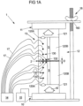
- FIG. 1A shows a measuring device 1 for measuring a thermal conductivity of a sample 2.
- the measuring device 1 comprises a heat source 10 and a heat sink 11.
- a sample holder 12 is arranged between the heat source 10 and the heat sink 11.
- FIG. The sample holder fixes the sample 2, in this case between the heat source 10 and the heat sink 11.
- the sample 2 is here in the form of a solid, namely a (eg disk-shaped) platelet or in the form of a pasty or thixotropic mass.
- the sample 2 has two parallel planar surfaces opposite to each other, which are in contact with the sample holder 12 and form the two large surfaces of the sample 2 in the form of a plate.
- the measuring device 1 also includes, in particular, a temperature sensor arrangement 13, which will be discussed in detail further below.
- the heat source 10 is designed in the form of an electric heater, although other types of heat source are also conceivable.
- the heat source 10 is connected to a power pack 15 which supplies the heat source 10 with electrical power. In this way it is possible to generate and release a defined amount of heat.
- the heat source 10 is in thermally conductive contact with one or more of the (warm) components of the sample holder 12.
- One or more of the (cold) components of the sample holder 12 are also in thermally conductive contact with the heat sink 11.
- connection block 121 of the sample holder 12 is in surface contact with the heat source 10.
- the connection block 121 is also in surface contact with several holding parts, in this case with a first holding part 120A and a second holding part 120B.
- the holding parts 120A, 120B are in turn each in flat contact with one of the two surfaces of the sample 2 facing the heat source 10.
- the sample 2 has a surface facing the heat sink 11 parallel to the surface facing the heat source 10 .
- the sample 2 is in planar contact with a further first holding part 120A and a further second holding part 120B.
- the further holding parts 120A, 120B are in surface contact with a further connection block 121.
- the further connection block 121 is in thermally conductive connection with the heat sink 11.
- the heat sink 11 comprises, for example, cooling fins or water cooling.
- connection blocks 121 are made of a heat conductor, for example the first material.
- the connecting blocks 121 are formed integrally with the respective first support part 120A and form part of this respective first support part 120A.
- Each of the holding parts 120A, 120B of the sample holder 12 exerts a holding force on the sample 2 when the sample 2 is fixed in the sample holder 12 as intended.
- the two first holding parts 120A consist (apart from optional coatings of the first and/or second holding parts 120A, 120B) from a first material, the two second holding parts 120B from a second material.
- the first material has a different thermal conductivity, namely a higher thermal conductivity than the second material.
- the first material is a thermal conductor
- the second material is a thermal insulator.
- a thermal conductor conducts heat much better than the thermal insulator.
- the first material is aluminum or an aluminum alloy with a thermal conductivity of typically more than 75 W/(m*K).
- the second material is polyetheretherketone (PEEK) with a thermal conductivity of typically 0.25 W/(m ⁇ K).
- PEEK polyetheretherketone
- the heat given off by the heat source 10 thus flows along a heat flow direction W (in Figure 1A symbolized by arrows) through the (warm) first holding part 120A, through the sample 2 and through the further (cold) first holding part 120A to the heat sink 11. Only a negligible proportion of the heat flows via the second holding parts 120B.
- the use of the second holding parts 120B significantly reduces the cross-sectional area of the sample 2 through which heat flows, compared to a configuration with holding parts all made of the first material, and thus the heat flux density is adjusted. This makes it possible to measure samples 2 with very high thermal conductivities. At the same time, however, a stable holding of the sample 2 is ensured by the second holding parts 120B, which can be important for thin and flexible film materials as a sample, for example.
- the heat source 10 is set up to provide a constant flow of heat.
- the heat sink 11 takes a constant at a constant temperature per unit time amount of heat up.
- a state of equilibrium is established in the measuring device 1 .
- this equilibrium state there is a temperature profile with temperatures that have a linear profile within the first holding parts 120A (with a temperature gradient in the direction from the heat sink 11 to the heat source 10).
- the measuring device 1 includes the temperature sensor arrangement 13 .
- the temperature sensor arrangement 13 comprises a plurality of temperature sensors 130. In principle, two temperature sensors 130 spaced apart along the heat flow would already be sufficient on both sides of the sample 2; a measurement is even possible with only a total of three temperature sensors 130.
- the temperature sensor arrangement 13 comprises a plurality on both sides of the sample 2, namely five temperature sensors 130, four temperature sensors 130 being spaced apart from one another along the heat flow direction W on one of the first holding parts 120A.
- another (optional) temperature sensor 130 is arranged perpendicular to the heat flow direction W at a distance from one of the other temperature sensors 130, in this case at the same distance from the sample 2 as this one of the other temperature sensors 130. A particularly high measurement accuracy near the sample 2 can be achieved as a result.
- the temperature sensors 130 are according to FIG Figure 1A each in the form of a resistance thermometer (resistance temperature device, RTD), although other types of temperature sensors or thermocouples are also possible.
- RTD resistance temperature device
- the temperature sensors 130 are fixed, for example, to the surface of the respective first holding part 120A.
- the temperature sensors 130 are embedded in the material of the first holding part 120A or incorporated in corresponding receptacles therein.
- the measured temperature values of the temperature sensors 130 are recorded by an evaluation unit 14 of the measuring device 1 , which for this purpose is operatively connected to each of the temperature sensors 130 via cable connections 17 .
- the effective thermal resistance R th,eff corresponds to the sum of the sample thermal resistance R th,sample and the contact thermal resistances R tn,O1 , R th,O2 at the interfaces between the sample 2 and the respective first holding parts 120A.
- the thermal resistances of the first holding parts 120A are also shown.
- the thermal conductivity ⁇ can be determined using the slope of the resulting straight line.
- the number of measured samples can be increased and/or a linear regression can also be used. The aforementioned calculations can be carried out using the evaluation unit 14 designed for this purpose.
- the measuring device 1 can have an optical or mechanical measuring device for characterizing the sample layer thickness.
- the contact thermal resistances R th,O1 , R th,O2 depend on the pressure with which the first holding parts 120A are pressed against the sample 2 .
- the measuring device 1 comprises a clamping device 16 in the form of a screw clamp, which presses the holding parts 120A, 120B against the sample 2 on both sides.
- the clamping device 16 also build up pressure pneumatically, hydraulically or by means of one or more springs.
- the clamping means 16 includes a corresponding pressure sensor 160, which can display the pressure exerted and/or is operatively connected to the evaluation unit 14.
- several measurements can also be carried out with different contact pressures using the clamping device 16 in order to determine the pressure dependence of the effective thermal conductivity ⁇ .
- connection blocks 121 are optional and can be used to securely hold the holding parts 120A, 120B and/or to distribute the heat from the heat source homogeneously.
- the holding parts 120A, 120B could also be in contact with the heat source 10 and/or the heat sink 11 without the interposition of a connecting block 121.
- the holding parts 120A, 120B are in the present case in the form of holding blocks or holding beams and all have essentially the same shape (namely in particular that of a cuboid) and size.
- the first holding parts 120A and the second holding parts 120B are spaced from each other.
- a gap S is formed between the first and second holding parts 120A, 120B and the sample 2 on both sides of the sample 2, respectively.
- the gap is specifically an air gap; alternatively, it is possible for the gap to be partially or completely filled, for example, with an insulating material such as an aerogel or a foam resin.
- the width of the gap S can be varied by laterally displacing the first and/or second holding parts 120A, 120B before tightening the clamping means 16.
- the first holding parts 120A are arranged so that the direction of heat flow through the sample 2 is parallel to the thickness D of the sample 2.
- the first and second holding parts 120A, 120B on the heat source 10 side of the sample 2 are mirror images (mirrored axis) of the first and second holding parts 120A, 120B on the heat sink 11 side of the sample 2.
- Figure 1B 12 shows the connection blocks 121 and the holding parts 120A, 120B of the measuring device 1 according to FIG Figure 1A , but in a different arrangement than in Figure 1A .
- the other components of the measuring device 1 are in Figure 1B not shown again for the sake of clarity.
- the holding parts 120A, 120B of the sample holder 12 can be arranged crosswise.
- the first and second holding parts 120A, 120B are arranged crosswise. This gives within the sample 2 a heat flow direction W (at least in sections) perpendicular to the thickness of the sample 2.
- the measuring device 1 (with the Figure 1B arranged holding parts 120A, 120B) to measure the thermal conductivity of the sample 2 in a spatial direction perpendicular to the thickness D of the sample 2, i.e. parallel to the two large surfaces of the sample 2.
- a rechargeable battery can be used as the sample 2, such as a lithium Ion cell with a complex, anisotropic internal structure.
- One of the temperature sensors 130 is arranged close to the gap S and close to the sample 2, which allows a particularly accurate measurement.
- the width of the gap S can also be varied in this arrangement by laterally displacing the first and/or second holding parts 120A, 120B before the clamping means 16 is clamped sample adjustable.
- the measuring device 1 thus allows a sample 2 in the form of a small plate to be clamped in such a way that the holding force of the clamping means 16 acts parallel to the thickness of the sample, but the thermal conductivity can be measured perpendicular to the thickness of the sample.
- This has the advantage of easy fixation of the sample.
- the same sample 2 can be used to measure the thermal conductivity with the same measuring device 1 in different spatial directions. Since some materials are brittle, it is often not possible to produce platelets, e.g. transverse to the fiber direction, or only with great inaccuracy or with great effort. This can also lead to large measurement inaccuracies, especially if the fibers are wavy.
- the holding parts 120A, 120B can be moved, in particular removed, when the clamping means 16 is released.
- the measuring device 1 can thus be easily installed in the arrangement according to FIG Figure 1A and in accordance with the arrangement Figure 1B operate in order to determine a measurement of the thermal conductivity in several, in particular all, spatial directions of the sample 2 by changing the temperature gradient.
- the measuring device 1 thus corresponds to a kit that can also include additional holding parts 120A, 120B, an additional heat source 10 and/or an additional heat sink 11 .
- the holding parts 120A, 120B can also be firmly attached to the connecting blocks 121 or directly to parts of the clamping means 16.
- the temperature sensors 130 of the temperature sensor assembly 13 are attached to the first holding parts 120A.
- further temperature sensors can also be attached to one or all of the second holding parts 120B, for example to increase the measuring accuracy.
- Figure 1C 12 shows again, in a schematic, perspective view, the general configuration of the holding parts 120A, 120B of the holding device 1 according to FIG Figure 1A , wherein the other components of the measuring device 1 are not shown for the sake of clarity.
- FIG. 1C four positions P1-P4 are provided, at each of which a holding part 120A, 120B is arranged.
- a first position P1 is according to Figure 1C arranged at the top left, a second position P2 at the top right, a third position P3 at the bottom left and a fourth position P4 at the bottom right.
- “Top” means the side of the sample 2 facing the heat sink 11 and "bottom” means the side facing the heat source 10 (and the side facing away from the heat sink 11) of the sample 2.
- the sample 2 separates the upper and lower holding parts 120A, 120B along a vertical axis from each other.
- the terms “left” and “right” refer to a left and right side of sample 2, respectively, with the left and right sides of sample 2 being offset from one another in a horizontal axis perpendicular to the vertical axis.
- Table 1 below presents a selection of possible configurations of first support members 120A ("first material”) and second support members 120B ("second material”), with some other configurations being possible.
- Table 1 Selection of possible arrangements with four holding parts. variant P1 p2 P3 P4 1 first material second material first material second material 2 first material second material second material first material 3 second material first material second material first material 4 second material first material first material first material
- Variant 1 corresponds to the arrangement according to Figure 1A
- Variant 2 corresponds to the arrangement according to Figure 1B
- Variant 3 corresponds to a vertically mirrored arrangement compared to variant 1.
- Variant 4 has an asymmetrical arrangement.
- a second holding part 120B is only arranged at one position P1, while first holding parts 120A are arranged at all other positions P2-P4. This makes it possible to use a (superimposed) Carry out measurement in two mutually perpendicular spatial directions through the sample 2.
- the temperature sensor arrangement 13 comprises a plurality of temperature sensors 130 (spaced apart along the heat flow direction W) on each of the first holding parts 120A.
- FIG Figure 1A shows a schematic, perspective view of a general configuration with a total of six holding parts 120A, 120B, the remaining components of FIG Figure 1A shown measuring device 1 for the sake of clarity are not shown.
- a first position P1 is according to 2 arranged at the top left, a second position P2 at the top center, a third position P3 at the top right, a fourth position P4 at the bottom left, a fifth position P5 at the bottom center and a sixth position P6 at the bottom right.
- the indications "above”, “below”, “left” and “right” according to those Figure 1C are equivalent to.
- Table 2 below provides a selection of possible arrangements of first support members 120A ("first material”) and second support members 120B ("second material”) at positions P1-P6, respectively 2 represent.
- Table 2 Selection of possible arrangements with six holding parts. variant P1 p2 P3 P4 P5 P6 5 first material second material first material second material first material second material 6 first material first material second material second material first material first material 7 first material second material first material first material second material first material 8th first material second material second material second material second material second material first material
- Variant 5 corresponds to the arrangement according to 2 .
- the heat from the heat source 10 flows through the first holding part 120A at the (middle) fifth position P5 into the sample 2.
- Variant 6 enables a simultaneous measurement in several spatial directions through the sample 2.
- the thermal conductivity of the sample 2 parallel to the thickness D of the sample 2 can be measured by means of the first holding parts 120A at the second and fifth position P2, P5.
- a measurement perpendicular to the thickness D of the sample 2 is possible in each case by means of the first holding parts 120A at the first and fifth positions P1, P5 and simultaneously by means of the first holding parts 120A at the second and sixth positions P2, P6. This double measurement enables high measurement accuracy.
- Variant 7 enables the thermal conductivity of sample 2 to be measured twice at the same time in a direction along the thickness D of sample 2.
- the first holding parts 120A through which the heat flow from the heat source to the heat sink passes are spaced from each other in a direction perpendicular to the sample thickness by a second holding part 120B.
- This enables measurement perpendicular to the thickness D of the sample 2, with the heat flowing through the sample 2 over a particularly long distance.
- This allows materials with a particularly high thermal conductivity to be measured (e.g. with a thermal conductivity of 300 W/(m K) or more).
- FIG. 3 shows in a schematic, perspective view a general configuration with a total of eight holding parts 120A, 120B, the remaining components of FIG Figure 1A shown measuring device 1 for the sake of clarity again not shown.
- positions P1-P8 are provided, at each of which a holding part 120A, 120B is arranged.
- the first four positions P1-P4 are arranged on one side (above) of the sample 2.
- the first four positions P1-P4 are arranged at the four corners of the sample 2, which is rectangular here.
- the remaining four positions P5-P8 are arranged on the opposite side (below) of sample 2, present in the same pattern as the first four positions P1-P4.
- the sample 2 is fixed at four locations by a pair of opposing holding members 120A, 120B, respectively. All positions P1-P8 are spaced from each other.
- Table 3 below presents a selection of possible arrangements of first and second holding parts 120A, 120B in the arrangement according to FIG 3 represent.
- Table 3 Selection of possible arrangements with eight holding parts. variant P1 p2 P3 P4 P5 P6 P7 P8 9 first material second material second material second material second material first material first material 10 first material second material second material second material first material first material first material 11 first material first material second material second material second material first material first material 12 first material second material first material second material second material first material second material first material first material
- the variant 9 corresponds to the arrangement according to 3 . With this, the thermal conductivities in two perpendicular spatial directions through the sample 2, each perpendicular to the thickness of the sample 2, can be measured simultaneously.
- Variant 10 enables the thermal conductivity of the sample to be measured simultaneously in all three spatial directions (one of the spatial directions extends parallel to the direction of thickness D of sample 2).
- the variant 11 enables a simultaneous multiple measurement along the same spatial direction perpendicular to the thickness D of the sample 2. This allows a particularly high level of accuracy.
- Variant 12 enables the average thermal conductivity to be measured in both vertical spatial directions perpendicular to the thickness D of sample 2.
- FIG. 4 shows a general configuration with a total of two holding parts 120A, 120B in a schematic, perspective view, the remaining components of FIG Figure 1A shown measuring device 1 for the sake of clarity are again not shown.
- the first and the second material of the two holding parts 120A, 120B are neither heat insulators here, but have different thermal conductivity from one another.
- Temperature sensors 130 of the temperature sensor arrangement 13 are attached here to the first and to the second holding part 120A, 120B. This results in the representation of the measured temperature values according to 8 on the two sides of sample 2 a different slope of the respective straight line.
- FIG. 5 shows another possible arrangement of the individual components of the measuring device 1 according to FIG Figure 1A , where the remaining components of the in Figure 1A shown measuring device 1 for the sake of clarity are not shown.
- the view corresponds to the view according to Figure 1C .
- the heat source 10 and the connection block 121 are arranged side by side.
- the heat source 10 is in thermally conductive communication with the first holding part 120A at the first position P1.
- the heat source 10 is not in thermally conductive connection with the second holding part 120B (except via sample 2) at the second position P2.
- the clamping means 16 provides thermal insulation for the heat source 10 and/or the connection block 121 comprises or consists of a thermal insulator.
- a first and a second holding part 120A, 120B are in surface contact with the sample 2 and are arranged reversed with respect to the previously mentioned holding parts 120A, 120B (on the warm side of the sample).
- the further first holding part 120A is arranged at the fourth position P4 and is in thermally conductive connection with the heat sink 11.
- the further second holding part 120B is arranged at the third position P3 and is in planar contact with the further connecting block 121.
- the connecting blocks 121 are the same Height difference of the heat source 10 and the heat sink 11 from.
- FIG Figure 6 shows a further configuration with a total of eight holding parts 120A, 120B, the remaining components of FIG Figure 1A shown measuring device 1 for the sake of clarity are not shown.
- two heat sources 10 and two heat sinks 11 are provided (although it would alternatively also be conceivable to provide one heat source 10 and two heat sinks 11 or two heat sources 10 and one heat sink 11).
- All of the heat sources 10 and heat sinks 11 are arranged on one side of the sample 2 .
- Each of the heat sources 10 and heat sinks 11 is in thermally conductive connection with the sample 2 via a respective first holding part 120A.
- a first holding part 120A is arranged at each of the first four positions P1-P4.
- a second holding part 120B is arranged on the opposite side of the sample 2 at the remaining four positions P5-P8, respectively.
- connection blocks 121 are used for height compensation when clamping with the clamping device 16 (see Figure 1A ). It is also conceivable to replace several or all of the (four) second holding parts 120B with a (large) second holding part extending over several, in particular over all of the fifth to eighth positions P5-P8.
- the arrangement according to 6 enables a two-dimensional measurement of the thermal conductivity of the sample 2.
- the components provided with connections or leads are all arranged on one side of the sample 2, which allows a simplified assembly of the measuring device 1.
- thermo sensors it is possible in all variants described to also attach temperature sensors to one or all of the second holding parts 120B, for example in the same way as to the first holding parts 120A. This can allow further measurements, for example if a non-negligible portion of the heat flows both through the first holding parts 120A and through the second holding parts 120B. This can be the case, for example, when neither the first material nor the second material is a heat insulator.
- the different thermal conductivities of the first and the second material result in different gradients in one of the 8 corresponding representation. In this way, particularly precise measurements can be achieved by simultaneously analyzing the temperature measurement values of the temperature sensors 130 on the first and second holding parts 120A, 120B.
- FIG. 7 shows another possible arrangement of two first holding parts 120A and two second holding parts 120B' for the measuring device 1 according to FIG Figure 1A .
- the two first holding parts 120A clamp the sample 2 between the heat source 10 and the heat sink 11 (see FIG Figure 1A ).
- the sample 2 has a smaller cross-sectional area than the first holding parts 120A, so that there are gaps between the outer contour of the first holding parts 120A and the sample 2 (at least one gap is formed depending on the arrangement of the sample 2).
- the second holding parts 120B ⁇ fill up the gaps.
- the second holding parts 120B' and the sample 2 together have the same cross-sectional area as the first holding parts 120A (along parallel planes). In this way, particularly narrow samples 2 or samples 2 with a particularly high thermal conductivity can be measured.
- the second holding parts 120B' are made of a heat insulator and support the sample 2 so that it is not broken despite the pressure from the clamp 16.
- step S100 the measuring device 1 is provided.
- step S101 the sample 2 is fixed by means of the sample holder 12 of the measuring device 1, in particular by exerting a holding force of each of the holding parts 120A, 120B on the sample 2 as a result of a force exerted by the clamping means 16.
- step S102 a temperature gradient is generated by means of the heat source 10 and the heat sink 11 of the measuring device 1. A state of equilibrium with a constant temperature curve is awaited.
- step S103 the thermal conductivity of the sample 2 is determined using measured temperature values determined by means of the temperature sensor arrangement 13 of the measuring device 1 .
- the above in connection with the Figures 8 and 9 described calculations are made, preferably by means of the evaluation unit 14.
- the heat flow density in the sample 2 can be adjusted via the contact areas between the first holding parts 120A and the sample 2 and via the ratio of the sample cross section to the sample thickness.
- one of the previously described arrangements can thus be used, which has correspondingly large or small contact areas.
- an arrangement with only a comparatively small contact area of the sample 2 with the first holding parts 120A can be used, e.g. one of the variants 8 or 11.
- the ratio of the sum of the contact areas of the second holding parts 120B with the sample 2 is selected to be the sum of the contact areas of the first holding parts 120A with the sample 2 in proportion to the thermal conductivity of the sample 2.
- the ratio can be, for example, one tenth or one hundredth (or a value in between) of the value of the thermal conductivity of the sample in W/(m.K).
- the thermal conductivity of anisotropic materials can be determined in all spatial directions (in the longitudinal and the two transverse directions of the sample) without knowledge of further material parameters.
- materials can be measured in a large measuring range, e.g. from 0.1 to 400 W/(m K).
- the measuring device 1 can of course be used or configured in any spatial position.
- the in Figure 1A The measuring device 1 shown can also be used rotated by 90° or 180°.
- the measuring device 1 allows the relative orientation of the sample 2 in the thermal field to be selected along all spatial axes.
- the thermal conductivity of the sample 2 can be determined separately for all spatial directions in the state of thermal equilibrium (stationary state).
- the heat flux density can be regulated in this way that high and very high thermal conductivities can also be characterized. Substance-specific values are not necessary for the measurement.
- the heat flow can be regulated in such a way that the waiting time until a temperature constant is set is comparatively short.
- the heat flow density can be regulated by means of the measuring device 1 via the contact area and via the ratio of the sample cross-section to the sample section. This makes it possible to measure samples 2 with very high thermal conductivity.
- FIG. 11 shows another possible arrangement of heat sources 10, heat sinks 11 and holding parts 120A, 120B.
- a total of four holding parts 120A, 120B are provided, specifically two first holding parts 120A and two second holding parts 120B.
- all holding parts 120A, 120B each have the same shape.
- Two holding parts 120A, 120B are arranged on one side of the sample 2, another two holding parts 120A, 120B on the opposite side of the sample 2.
- the sample 2 is arranged between two pairs of holding parts 120A, 120B.
- Each pair of holding parts 120A, 120B comprises a first holding part 120A and a second holding part 120B.
- the two first holding parts 120A are aligned along a common (first) axis.
- the two second holding parts 120B are aligned along a common (second) axis.
- the first axis and the second axis are offset from one another (aligned parallel to one another in the example shown).
- the two holding parts 120A, 120B are spaced from each other.
- the two holding parts 120A, 120B on each side of the sample do not touch each other. All four holding parts 120A, 120B touch the sample 2.
- the sample 2 is clamped at a first area between two holding parts, here between the two first holding parts 120A.
- the sample 2 is not in contact with any holding member.
- the sample is clamped between two holding parts, here between the two second holding parts 120B.
- two heat sources 10 and two heat sinks 11 are provided, concretely, a heat source 10 and a heat sink 11 on one side of the sample 2 and a heat source 10 and a heat sink 11 on the opposite side of the sample 2.
- Each of the two first holding parts 120A connects a heat source 10 thermally conductive with the sample 2.
- Each of the two second holding parts 120B thermally conductively connects the sample 2 with a heat sink 11.
- first holding parts 120A are interchanged with the second holding parts 120B.
- first holding part 120A and the second holding part 120B are opposite one another on one side of the sample 2 11 arranged reversed.
Landscapes
- Physics & Mathematics (AREA)
- Health & Medical Sciences (AREA)
- Life Sciences & Earth Sciences (AREA)
- Chemical & Material Sciences (AREA)
- Analytical Chemistry (AREA)
- Biochemistry (AREA)
- General Health & Medical Sciences (AREA)
- General Physics & Mathematics (AREA)
- Immunology (AREA)
- Pathology (AREA)
- Investigating Or Analyzing Materials Using Thermal Means (AREA)
Description
- Die Erfindung betrifft eine Messvorrichtung zur Messung einer Wärmeleitfähigkeit einer Probe nach Anspruch 1 sowie ein Verfahren zur Messung einer Wärmeleitfähigkeit einer Probe nach Anspruch 14.
- Eine derartige Messvorrichtung umfasst eine Wärmequelle, eine Wärmesenke, eine Probenhalterung und eine Temperatursensoranordnung. Die Probenhalterung ist zur Fixierung der Probe eingerichtet und umfasst mehrere zum Halten der Probe ausgebildete Halteteile. Dabei ist zumindest ein Halteteil eingerichtet, die Wärmequelle mit der Probe wärmeleitend zu verbinden. Zumindest ein weiteres Halteteil ist eingerichtet, die Probe wärmeleitendend mit der Wärmesenke zu verbinden. Die Temperatursensoranordnung ist eingerichtet, an mehreren Orten entlang des Wärmeflusses zwischen der Wärmequelle und der Wärmesenke Temperaturmesswerte zu ermitteln, um die Wärmeleitfähigkeit der Probe zu bestimmen.
- Eine Messvorrichtung ist im Standard ASTM D5470 (internationale Standardisierungsorganisation) beschrieben. Die Probe wird in Form eines Plättchens zwischen zwei Messbalken geklemmt, an denen eine Reihe von Temperatursensoren angeordnet ist. Die gemessenen Temperaturen werden auf beiden Seiten der Probe extrapoliert, um eine thermische Impedanz der Probe zu ermitteln. Die thermische Impedanz mehrerer Proben desselben Materials und mit unterschiedlicher Probendicke wird auf diese Weise gemessen und gegen die Probendicke aufgetragen, wobei sich eine lineare Abhängigkeit zeigt. Die Wärmeleitfähigkeit kann anhand der Steigung der thermischen Impedanz mit der Probendicke ermittelt werden.
- Die Wärmeleitfähigkeit ist ein Maß für die Fähigkeit eines Materials, Wärme zu übertragen. Da die Wärmestrahlung bei Temperaturen unterhalb von 500 °C in der Regel eine untergeordnete Rolle spielt, ist die Wärmeleitung häufig die maßgebliche Größe für die transportierte thermische Energie, wenn Materialien mit unterschiedlichen thermischen Energien miteinander in Kontakt treten. Die Wärmeleitfähigkeit in W/(m·K) ist eine temperaturabhängige Materialkonstante und wird für den eindimensionalen Fall durch das Fourier-Gesetz besch rieben.
- In vielen Bereichen, insbesondere bei moderner Hochleistungselektronik, ist es von zunehmender Bedeutung, die Wärmeleitfähigkeit der eingesetzten Materialien präzise zu bestimmen.
- Die Wärmeleitfähigkeit eines Materials wird zum Beispiel bestimmt, um Kühlkörper für Geräte und Bauteile zu entwerfen (thermisches Management), zur Überwachung und Optimierung von Herstellungsverfahren (bspw. für Medikamentenzusammensetzungen oder in der Lebensmitteltechnologie) oder um transportierte Wärme in Heizkraftwerken oder Geothermieanlagen zu berechnen. Daher wächst der Bedarf an zuverlässigen Verfahren, die in der Lage sind, ein breites Spektrum von Materialien und ihren thermischen Eigenschaften zu charakterisieren.
- Zahlreiche Verbundmaterialien sind wegen Schichtstrukturen oder bedingt durch ihre Inhaltstoffe mikroskopisch oder gar makroskopisch anisotrop aufgebaut. Verbreitete Anwendungen dafür sind Solarzellen, Gewebe/Faser-verstärkte Laminat-Konstruktionen und Lithium-Ionen-Zellen, insbesondere für Elektrofahrzeuge. Die aktuelle Entwicklung hin zu anisotropen Kompositen und faserverstärkten Verbundmaterialien erfordert neue Charakterisierungsmethoden, die den strukturellen Besonderheiten der Materialien gerecht werden und präzise und richtungsselektive Eigenschaftsmessungen ermöglichen.
- Mit der bekannten Messvorrichtung nach ASTM D5470 ist es möglich, die Wärmeleitfähigkeit der Probe in einer Raumrichtung zu bestimmen, nämlich in Richtung der Probendicke. Für anisotrope Materialien ist es wünschenswert, die Wärmeleitfähigkeit in mehreren Raumrichtungen der Probe zu ermitteln. So haben beispielsweise Holz oder faserverstärkte Verbundmaterialien entlang der Fasern eine andere Wärmeleitfähigkeit als quer zu den Fasern. Für eine Messung in einer weiteren Raumrichtung müssen bei der bekannten Messvorrichtung anders geschnittene Plättchen hergestellt werden. Bei einigen Verbundmaterialien sind derart geschnittene Plättchen aber nicht ausreichend stabil. Zudem ist eine solche Probenpräparation und Messung zeitaufwändig und umständlich und aufgrund von möglicherweise nicht homogen verlaufenden Fasern in der Probe auch häufig mit Ungenauigkeiten behaftet.
- Ferner können mit der bekannten Messvorrichtung Wärmeleitfähigkeiten von Materialien mit besonders hoher Wärmeleitfähigkeit nicht oder nur mit oftmals großen Ungenauigkeiten gemessen werden.
- Die
US 6,331,075 B1 und dieWO 2017/073479 A1 beschreiben weitere Messvorrichtungen. - Ausgehend vom Fourier-Gesetz ist ein experimenteller Weg zur Charakterisierung der Wärmeleitfähigkeit eine ortsaufgelöste Temperaturmessung an der Probe unter stationärem Wärmestrom. Ein solches Messverfahren beschreiben Tritt, T. M., und Weston, D. in "Measurement Techniques and Considerations for Determining Thermal Conductivity of Bulk Materials", Thermal Conductivity, T. M. Tritt, ed., Springer, New York, 2004, Seiten 187 bis 203.
- Neben den statischen Verfahren wurden verschiedene dynamische Verfahren entwickelt, bei denen durch eine periodisch veränderliche oder gepulste Wärmequelle eine kurzzeitige Temperaturänderung in der Probe verursacht wird. Hierzu zählen insbesondere die nachfolgenden Verfahren:
Maldonado, O.,"Pulse Method for Simultaneous Measurement of Electric Thermopower and Heat Conductivity at Low Temperatures", Cryogenics, 32(10), 1992, Seiten 908 bis 912, beschreibt ein gepulstes Messverfahren. - Stalhane, B., und Pyk, S., "New Method for Determining the Coefficients of Thermal Conductivity", Tek. Tidskr., 61(28), 1931, Seiten 389 bis 393, beschreiben ein Heißdrahtverfahren.
- Bouguerra, A. et al., "Measurement of Thermal Conductivity, Thermal Diffusivity and Heat Capacity of Highly Porous Building Materials Using Transient Plane Source Technique", Int. Commun. Heat Mass Transfer, 28(8), 2001, Seiten 1065 bis 1078, beschreiben ein sogenanntes "Transient-Plane-Source"-Verfahren.
- Parker, W. J. et al., "Flash Method of Determining Thermal Diffusivity, Heat Capacity, and Thermal Conductivity", J. Appl. Phys., 32(9), 1961, Seiten 1679 bis 1684, beschreiben ein Laser-Flash-Verfahren.
- Die vorstehend genannten dynamischen Verfahren sind allerdings jeweils nur für einen bestimmten Bereich von messbaren Wärmeleitfähigkeiten ausgelegt und weisen einen komplexen Versuchsaufbau auf. Außerdem wird die Wärmeleitfähigkeit nicht direkt bestimmt sondern aus der thermische Diffusivität hergeleitet, wozu noch weitere Materialparameter ermittelt werden müssen.
- Die bekannten stationären und dynamischen Verfahren ermöglichen insbesondere keine oder keine zufriedenstellende Messung einer anisotropen Wärmeleitfähigkeit. Das Transient-Plane-Source-Verfahren und das Laser-Flash-Verfahren ermöglichen keine Unterscheidung der Wärmeleitfähigkeit in beide Richtungen der Ebene einer Probe. Die Transient-Plane-Methode erfordert für Materialien mit hoher Wärmeleitfähigkeit Proben in einer Größe, die oftmals nicht verfügbar ist.
- Der Erfindung liegt das Problem zugrunde, eine verbesserte Messvorrichtung bzw. ein verbessertes Messverfahren zur Messung einer Wärmeleitfähigkeit einer Probe bereitzustellen.
- Gelöst wird dieses Problem durch eine Messvorrichtung zur Messung einer Wärmeleitfähigkeit einer Probe gemäß Anspruch 1.
- Danach ist vorgesehen, dass ein erstes Halteteil der Probenhalterung ein erstes Material umfasst oder daraus besteht und ein zweites Halteteil der Probenhalterung ein zweites Material umfasst oder daraus besteht. Dabei weist das erste Material eine andere Wärmeleitfähigkeit auf als das zweite Material, wobei jeweils zumindest zwei Halteteile derart auf gegenüberliegenden Seiten der Probe angeordnet oder anordenbar sind, dass ein Wärmefluss von der Wärmequelle zur Wärmesenke durch die Probe senkrecht zur Wärmeflussrichtung durch eines oder mehrere der Halteteile verläuft, wenn die Probe mittels der Probenhalterung fixiert ist. Vorliegend sind zumindest zwei erste Halteteile und zumindest zwei zweite Halteteile vorgesehen, wobei die zumindest zwei ersten Halteteile auf gegenüberliegenden Seiten der Probe angeordnet oder anordenbar sind und die zumindest zwei zweiten Halteteile auf gegenüberliegenden Seiten der Probe angeordnet oder anordenbar sind.
- Die Wärmeleitfähigkeiten der beiden Halteteile unterscheiden sich insbesondere derart voneinander, dass eines der Halteteile ein guter Wärmeleiter (also als ein wärmeleitendes Halteteil ausgebildet ist) und ein anderes der Halteteile kein Wärmeleiter ist (also als ein wärmeisolierendes Halteteil ausgebildet ist). Dabei sind mehr als ein erstes Halteteil und mehr als ein zweites Halteteil vorgesehen, wobei die ersten Halteteile das erste Material umfassen oder daraus bestehen und die zweiten Halteteile das zweite Material umfassen oder daraus bestehen.
- Jedes der Halteteile der Probenhalterung steht in Berührung mit der Probe, wenn die Probe durch die Probenhalterung fixiert ist. Die Halteteile können jeweils einstückig ausgebildet sein. Die Wärmequelle weist im Betrieb der Messvorrichtung eine höhere Temperatur auf als die Wärmesenke. Beispielsweise umfasst die Wärmequelle eine Heizung. Die Wärmesenke kann Kühlrippen oder eine andere Kühlvorrichtung umfassen. Bei einer bestimmungsgemäßen Benutzung der Messvorrichtung fließt Wärme von der Wärmequelle durch zumindest eines der Halteteile, durch die Probe und durch zumindest ein weiteres der Halteteile zur Wärmesenke.
- Durch den Einsatz von Halteteilen mit unterschiedlichen Wärmeleitfähigkeiten kann ein Wärmfluss z.B. in eine Richtung durch die Probe gelenkt werden, um so die Wärmeleitfähigkeit in einer Richtung senkrecht zur Probendicke (also in der Probenebene) zu bestimmen. Die Halteteile sind also z.B. so angeordnet oder anordenbar, dass ein Wärmfluss in eine Richtung durch die Probe quer zur kürzesten Geraden zwischen der Wärmequelle und der Wärmesenke verläuft. Ferner erlauben die verschiedenen Wärmeleitfähigkeiten der Halteteile besonders genaue Messungen, insbesondere von gut wärmeleitenden Probenmaterialien.
- Die Wärmeleitfähigkeit des ersten Materials kann größer, insbesondere wesentlich größer, als die Wärmeleitfähigkeit des zweiten Materials sein, insbesondere mindestens das Fünffache oder sogar mindestens das Zehnfache der Wärmeleitfähigkeit des zweiten Materials betragen. Die Wärmeleitfähigkeit des isolierenden Halteteils liegt beispielsweise deutlich unter der zu erwartenden Wärmeleitfähigkeit der Probe.
- Das erste Material kann ein Wärmeleiter sein. Insbesondere kann das erste Material eine Wärmeleitfähigkeit von über 100 W/(m K) aufweisen. Alternativ oder zusätzlich ist das zweite Material ein Wärmeisolator, der z.B. eine Wärmeleitfähigkeit von unter 1 W/(m K) aufweist. So kann der Wärmefluss durch die Probe je nach Anordnung der Halteteile selektiv in eine bestimmte vorgegebene Wärmeflussrichtung gelenkt werden, um die Wärmeleitfähigkeit der Probe in einer bestimmten Richtung zu messen.
- Die Wärmeleitfähigkeiten der Halteteile können so ausgestaltet sein, dass ein Wärmefluss durch die zweiten Halteteile keinen wesentlichen Beitrag zum gesamten Wärmefluss bildet.
- Zwischen mehreren der Halteteile kann ein Spalt ausgebildet sein, insbesondere in Form eines Luftspalts. Die Probenhalterung ist so ausgebildet und eingerichtet, dass die Halteteile derart anordenbar sind, dass zwischen zumindest zwei Halteteilen ein Spalt ausgebildet ist. Hierdurch kann eine Strecke vorgegeben werden, entlang der die Wärme der Wärmequelle nur durch die Probe und nicht durch ein benachbartes Halteteil fließt, was eine besonders genaue Messung ermöglicht. Durch den Spalt sind die Halteteile, zwischen denen der Spalt ausgebildet ist, voneinander beabstandet.
- Der Spalt kann einstellbar sein, z.B. mittels einer Stellvorrichtung.
- Der Spalt kann zwischen zwei auf derselben Seite der Probe angeordneten Halteteilen ausgebildet sein, z.B. in einem Zwischenraum zwischen der Probe und der Wärmequelle oder zwischen der Probe und der Wärmesenke. Optional ist auf beiden Seiten der Probe zwischen jeweils zumindest zwei Halteteilen ein Spalt ausgebildet.
- Das erste Material kann Aluminium sein. Alternativ ist das erste Material z.B. Stahl, Messing, Kupfer, eine Kupferlegierung, eine Aluminiumlegierung, Bronze, Nickel, Molybdän, Wolfram eine Titanlegierung, Aluminiumoxid, Aluminiumnitrid, Siliciumnitrid oder Siliciumcarbid. Das zweite Material kann Polyetheretherketon (PEEK) sein oder z.B. Polyphenylsulfid, Polybutyleneterphthalat, Polyethersulfon, Acrylnitril-Butadien-Styrol, Polyetherimid, Harnstoff-Formaldehydharz, Polyethylenterphtalat oder eine Keramik mit geringer Wärmeleitfähigkeit wie Zirkonoxid. Aus diesen Materialien werden beispielsweise Paarungen eines ersten und eines zweiten Materials ausgewählt, die die vorstehenden Bedingungen für die Wärmeleitfähigkeiten aufweisen.
- Mehrere Halteteile, insbesondere alle Halteteile der Probenhalterung, können untereinander im Wesentlichen dieselbe Form und/oder Größe aufweisen. Hierdurch können die Halteteile ein und derselben Messvorrichtung unterschiedlich angeordnet werden, um die Probe zu fixieren. Hierdurch sind verschiedene Konfigurationen der Messvorrichtung möglich. Die verschiedenen Konfigurationen ermöglichen die Messung der Wärmeleitfähigkeit in unterschiedlichen Raumrichtungen durch die Probe mittels derselben Messvorrichtung und derselben Probe. Ferner vereinfacht die Ausbildung der Halteteile in derselben Form und Größe die Berechnung der Wärmeleitfähigkeit anhand der Temperaturmesswerte. Alternativ ist es aber selbstverständlich auch möglich, dass z.B. die Querschnitte des oder der ersten und zweiten Halteteile unterschiedlich sind.
- Zumindest zwei der Halteteile der Probenhalterung können vertauschbar anordenbar sein. Hierdurch wird eine besonders hohe Variabilität und besonders einfache Änderung der Konfiguration der Messvorrichtung ermöglicht.
- Beispielsweise stehen zumindest ein erstes Halteteil und zumindest ein zweites Halteteil in Berührung mit der Probe oder sind zur Messung der Wärmeleitfähigkeit der Probe in Berührung damit bringbar.
- Optional sind die Halteteile derart angeordnet oder anordenbar, dass eine der Wärmequelle und/oder eine der Wärmesenke zugewandte Seite der Probe (jeweils) nur teilweise von den Halteteilen bedeckt ist/sind.
- Optional sind nicht alle der Halteteile entlang derselben Achse angeordnet (oder zur Messung der Wärmeleitfähigkeit der Probe entlang derselben Achse anordenbar), sondern z.B. entlang zueinander versetzter Achsen.
- Es sind zumindest zwei erste Halteteile und zumindest zwei zweite Halteteile vorgesehen. Dies erlaubt eine einfache Messung der Wärmeleitfähigkeit in unterschiedlichen Raumrichtungen durch die Probe.
- Zwei erste Halteteile sind auf gegenüberliegenden Seiten der Probe angeordnet oder anordenbar. Zusätzlich sind zwei zweite Halteteile auf gegenüberliegenden Seiten der Probe angeordnet oder anordenbar. Hierdurch können die Halteteile mit unterschiedlichen Wärmeleitfähigkeiten so angeordnet werden, dass eine Messung der Wärmeleitfähigkeit einer Probe mit besonders hoher Wärmeleitfähigkeit ermöglicht wird.
- Die zumindest zwei ersten Halteteile und/oder die zumindest zwei zweiten Halteteile können senkrecht zu einer Wärmeflussrichtung von der Wärmequelle zur Wärmesenke (und/oder senkrecht zu einer kürzesten Geraden zwischen der Wärmequelle und der Wärmesenke) versetzt zueinander angeordnet oder anordenbar sein. Dies ermöglicht eine besonders gute Messung der Wärmeleitfähigkeit der Probe quer zur Dicke der Probe (und/oder quer zu einer kürzesten Geraden zwischen der Wärmequelle und der Wärmesenke).
- Die Halteteile sind derart angeordnet oder anordenbar, dass bei einem Wärmefluss von der Wärmequelle zur Wärmesenke die Wärmeflussrichtung durch die Probe senkrecht zur Wärmeflussrichtung durch eines oder mehrere der Halteteile verläuft, wenn die Probe mittels der Probenhalterung fixiert ist, insbesondere um eine Messung der Wärmeleitfähigkeit der Probe quer zur Dicke der Probe zu ermöglichen.
- Die Probenhalterung kann mehrere, z.B. zwei, drei oder vier Halteteile umfassen, die eingerichtet sind, die Wärmequelle mit der Probe wärmeleitend zu verbinden. Alternativ oder zusätzlich umfasst die Probenhalterung mehrere, z.B. zwei, drei oder vier Halteteile (insbesondere die gleiche Anzahl wie Halteteile, die die Wärmequelle mit der Probe wärmeleitend verbinden), die eingerichtet sind, die Probe wärmeleitendend mit der Wärmesenke zu verbinden. Hierdurch sind besonders vielfältige Messungen der Wärmeleitfähigkeit in verschiedenen Raumrichtungen durch die Probe möglich.
- Die Haltevorrichtung umfasst bevorzugt ein Spannmittel, welches eingerichtet ist, eine Kraft auf die Probenhalterung und damit auf die Probe auszuüben. Ein vom Spannmittel erzeugter Kraftfluss verläuft durch jeweils zumindest ein Halteteil beiderseits der Probe, insbesondere durch alle Halteteile der Probenhalterung. Das Spannmittel kann so ausgebildet sein, dass es eine spezifische Kraft ausübt, insbesondere derart, dass die Halteteile mit einem vorbestimmten Druck gegen die Probe gepresst werden. Das Spannmittel umfasst optional einen Drucksensor, der den vom Spannmittel ausgeübten Druck oder die vom Spannmittel ausgeübte Kraft angibt. Optional wird die Kontaktrauhigkeit in die Bestimmung der Wärmeleitfähigkeit einbezogen.
- Die Temperatursensoranordnung umfasst mehrere Temperatursensoren, die an zumindest einem der Halteteile angeordnet sind. Insbesondere kann die Temperatursensorvorrichtung mehrere Temperatursensoren, die an einem der Halteteile angeordnet sind, und mehrere weitere Temperatursensoren, die an einem weiteren der Halteteile angeordnet sind, umfassen.
- Die Messvorrichtung kann mehrere (insbesondere voneinander beabstandete) Wärmequellen und/oder mehrere (insbesondere voneinander beabstandete) Wärmesenken umfassen. Die mehreren Wärmequellen und/oder Wärmesenken können jeweils auf einander gegenüberliegenden Seiten der Probe angeordnet oder anordenbar sein. Hierdurch lassen sich Wärmeflüsse erzeugen, die präzise Messungen von Wärmeleitfähigkeiten ermöglichen können. Die Wärmequelle(n) und/oder Wärmesenke(n) werden bevorzugt so angeordnet und eingerichtet, dass sich ein (im Wesentlichen) linearer thermischer Gradient einstellt.
- Das genannte Problem wird auch durch ein Verfahren zur Messung einer Wärmeleitfähigkeit einer Probe gemäß Anspruch 14 gelöst.
- Ein solches Verfahren umfasst die folgenden Schritte:
- Bereitstellen einer Messvorrichtung nach einer beliebigen, hierin beschriebenen Ausführung;
- Fixieren einer Probe mittels der Probenhalterung der Messvorrichtung;
- Erzeugen eines Temperaturgradienten mittels der Wärmequelle und der Wärmesenke der Messvorrichtung; und
- Bestimmen der Wärmeleitfähigkeit der Probe unter Verwendung von mittels der Temperatursensoranordnung der Messvorrichtung bestimmter Temperaturmesswerte und des durch die Wärmequelle bereitgestellten Wärmestroms.
- Das Bestimmen der Wärmeleitfähigkeit kann insbesondere das Wiederholen der Schritte des Fixierens einer Probe, des Erzeugens eines Temperaturgradienten und des Bestimmens von Temperaturmesswerten mit mehreren Proben aus dem gleichen Material mit unterschiedlichen Schichtdicken umfassen.
- Hierdurch kann es ermöglicht werden, die Wärmeleitfähigkeit in einer Richtung quer zur Probendicke zu bestimmen. Die verschiedenen Wärmeleitfähigkeiten der Halteteile können zudem besonders genaue Messungen ermöglichen, insbesondere von stark wärmeleitenden Probenmaterialien.
- Die Erfindung wird nachfolgend unter Bezugnahme auf die Figuren anhand von Ausführungsbeispielen näher erläutert werden. Es zeigen in schematischen Darstellungen:
- Fig. 1A
- eine Messvorrichtung zur Messung einer Wärmeleitfähigkeit einer Probe mit einer Probenhalterung mit zwei ersten und zwei zweiten Halteteilen;
- Fig. 1B
- Teile der Messvorrichtung gemäß
Fig. 1A in einer anderen Anordnung; - Fig. 1C
- mögliche alternative Anordnungen der vier Halteteile der Messvorrichtung gemäß
Fig. 1A in einer perspektivischen Ansicht; - Fig. 2
- mögliche alternative Anordnungen von sechs Halteteilen für die Messvorrichtung gemäß
Fig. 1A in einer perspektivischen Ansicht; - Fig. 3
- mögliche alternative Anordnungen von acht Halteteilen für die Messvorrichtung gemäß
Fig. 1A in einer perspektivischen Ansicht; - Fig. 4
- mögliche alternative Anordnungen von zwei Halteteilen für die Messvorrichtung gemäß
Fig. 1A in einer perspektivischen Ansicht; - Fig. 5
- eine mögliche alternative Anordnung von Komponenten der Messvorrichtung gemäß
Fig. 1A in einer perspektivischen Ansicht; - Fig. 6
- eine mögliche alternative Anordnung von acht Halteteilen, zwei Wärmequellen und zwei Wärmesenken für die Messvorrichtung gemäß
Fig. 1A in einer perspektivischen Ansicht; - Fig. 7
- eine mögliche alternative Anordnung von vier Halteteilen für die Messvorrichtung gemäß
Fig. 1A in einer perspektivischen Ansicht; - Fig. 8
- einen linearen Zusammenhang zwischen einer Position von Temperatursensoren und gemessen Temperaturen;
- Fig. 9
- Wärmewiderstände der Messvorrichtung gemäß
Fig. 1A ; - Fig. 10
- ein Verfahren zur Messung einer Wärmeleitfähigkeit einer Probe; und
- Fig. 11
- eine mögliche alternative Anordnung von Komponenten der Messvorrichtung gemäß
Fig. 1A in einer perspektivischen Ansicht. -
Fig. 1A zeigt eine Messvorrichtung 1 zur Messung einer Wärmeleitfähigkeit einer Probe 2. Die Messvorrichtung 1 umfasst eine Wärmequelle 10 und eine Wärmesenke 11. Zwischen der Wärmequelle 10 und der Wärmesenke 11 ist eine Probenhalterung 12 angeordnet. Die Probenhalterung fixiert die Probe 2, und zwar vorliegend zwischen der Wärmequelle 10 und der Wärmesenke 11. Die Probe 2 ist hier in Form eines Festkörpers, nämlich eines (z.B. scheibenförmigen) Plättchens oder in Form einer pastösen oder thixotropen Masse ausgebildet. Die Probe 2 hat zwei parallele, plane, einander gegenüberliegende Oberflächen, die mit der Probenhalterung 12 in Berührung stehen und die beiden großen Oberflächen der plättchenförmigen Probe 2 bilden. Die Messvorrichtung 1 umfasst ferner insbesondere eine Temperatursensoranordnung 13, auf die weiter unten im Detail eingegangen werden wird. - Die Wärmequelle 10 ist vorliegend in Form einer elektrischen Heizung ausgebildet, wobei auch andere Arten eine Wärmequelle denkbar sind. Die Wärmequelle 10 ist an ein Netzteil 15 angeschlossen, welches die Wärmequelle 10 mit elektrischem Strom versorgt. Auf diese Weise ist es möglich, eine definierte Wärmemenge zu erzeugen und abzugeben.
- Die Wärmequelle 10 steht in wärmeleitendem Kontakt mit einer oder mehreren der (warmen) Komponenten der Probenhalterung 12. Eine oder mehrere der (kalten) Komponenten der Probenhalterung 12 stehen ferner in wärmeleitendem Kontakt mit der Wärmesenke 11.
- Bei der Messvorrichtung 1 gemäß
Fig. 1A steht ein optionaler Verbindungsblock 121 der Probenhalterung 12 in flächiger Anlage mit der Wärmequelle 10. Der Verbindungsblock 121 steht ferner in flächiger Anlage mit mehreren Halteteilen, vorliegend mit einem ersten Halteteil 120A und einem zweiten Halteteil 120B. Die Halteteile 120A, 120B stehen wiederum jeweils in flächiger Anlage mit einer der Wärmequelle 10 zugewandten Oberfläche der genannten beiden Oberflächen der Probe 2. - Parallel zur der Wärmequelle 10 zugewandten Oberfläche weist die Probe 2 eine der Wärmesenke 11 zugewandte Oberfläche auf. An der der Wärmesenke 11 zugewandten Oberfläche steht die Probe 2 in flächiger Anlage mit einem weiteren ersten Halteteil 120A und einem weiteren zweiten Halteteil 120B. An ihren der Probe 2 abgewandten Seiten stehen die weiteren Halteteile 120A, 120B in flächiger Anlage mit einem weiteren Verbindungsblock 121. Der weitere Verbindungsblock 121 steht in wärmeleitender Verbindung mit der Wärmesenke 11. Die Wärmesenke 11 umfasst z.B. Kühlrippen oder eine Wasserkühlung.
- Die Verbindungsblocks 121 sind aus einem Wärmeleiter hergestellt, beispielsweise aus dem ersten Material. Optional sind die Verbindungsblocks 121 einstückig mit dem jeweiligen ersten Halteteil 120A ausgebildet und bilden einen Teil dieses jeweiligen ersten Halteteils 120A.
- Jedes der Halteteile 120A, 120B der Probenhalterung 12 übt eine Haltekraft auf die Probe 2 aus, wenn die Probe 2 in der Probenhalterung 12 bestimmungsgemäß fixiert ist.
- Die beiden ersten Halteteile 120A bestehen (wenn man von optionalen Beschichtungen der ersten und/oder zweiten Halteteile 120A, 120B absieht) aus einem ersten Material, die beiden zweiten Halteteile 120B aus einem zweiten Material. Dabei ist vorgesehen, dass das erste Material eine andere, nämlich vorliegend eine höhere Wärmeleitfähigkeit aufweist als das zweite Material. Das erste Material ist ein Wärmeleiter, das zweite Material ist ein Wärmeisolator. Ein Wärmeleiter leitet Wärme wesentlich besser als der Wärmeisolator. Im gezeigten Beispiel ist das erste Material Aluminium oder eine Aluminiumlegierung mit einer Wärmeleitfähigkeit von typischerweise mehr als 75 W/(m·K). Das zweite Material ist Polyetheretherketon (PEEK) mit einer Wärmeleitfähigkeit von typischerweise 0,25 W/(m·K). Alternativ sind andere Paarungen von Materialien möglich, wobei es vorteilhaft sein kann, wenn die Wärmeleitfähigkeit des ersten Materials zumindest fünfmal so groß, insbesondere etwa eine Größenordnung größer ist als die Wärmeleitfähigkeit des zweiten Materials.
- Die von der Wärmequelle 10 abgegebene Wärme fließt somit entlang einer Wärmeflussrichtung W (in
Fig. 1A durch Pfeile symbolisiert) durch das (warme) erste Halteteil 120A, durch die Probe 2 und durch das weitere (kalte) erste Halteteil 120A zur Wärmesenke 11. Über die zweiten Halteteile 120B fließt nur ein vernachlässigbarer Anteil der Wärme. Durch den Einsatz der zweiten Halteteile 120B wird gegenüber einer Konfiguration mit Halteteilen, die allesamt aus dem ersten Material bestehen, die Querschnittsfläche der Probe 2, durch die Wärme fließt, deutlich verkleinert und so die Wärmestromdichte angepasst. Hierdurch ist es möglich, Proben 2 mit sehr großen Wärmeleitfähigkeiten zu vermessen. Gleichzeitig ist aber eine stabile Halterung der Probe 2 durch die zweiten Halteteile 120B sichergestellt, was z.B. bei dünnen und flexiblen Folienmaterialien als Probe wichtig sein kann. - Die Wärmequelle 10 ist eingerichtet, einen konstanten Wärmestrom bereitzustellen. Die Wärmesenke 11 nimmt bei einer konstanten Temperatur pro Zeiteinheit eine konstante Wärmemenge auf. Hierdurch stellt sich in der Messvorrichtung 1 ein Gleichgewichtszustand ein. In diesem Gleichgewichtszustand liegt ein Temperaturprofil vor mit Temperaturen, die innerhalb der ersten Halteteile 120A einen linearen Verlauf aufweist (mit einem Temperaturgradienten in Richtung von der Wärmesenke 11 zur Wärmequelle 10).
- Zur Messung dieses Temperaturprofils umfasst die Messvorrichtung 1 die Temperatursensoranordnung 13. Hierzu ist die Temperatursensoranordnung 13 ausgebildet, an mehreren Stellen des Wärmeflusses von der Wärmequelle 10 zur Wärmesenke 11 beiderseits der Probe 2 Temperaturmesswerte zu ermitteln. Die Temperatursensoranordnung 13 umfasst mehrere Temperatursensoren 130. Grundsätzlich würden zwei entlang des Wärmeflusses beabstandete Temperatursensoren 130 auf beiden Seiten der Probe 2 bereits ausreichen, sogar mit nur insgesamt drei Temperatursensoren 130 ist eine Messung möglich. Vorliegend umfasst die Temperatursensoranordnung 13 beiderseits der Probe 2 aber jeweils eine Vielzahl, nämlich fünf Temperatursensoren 130, wobei jeweils vier Temperatursensoren 130 entlang der Wärmeflussrichtung W beabstandet zueinander an einem der ersten Halteteile 120A angeordnet sind. Jeweils ein weiterer (optionaler) Temperatursensor 130 ist senkrecht zur Wärmeflussrichtung W beabstandet von einem der anderen Temperatursensoren 130 angeordnet, vorliegend jeweils in demselben Abstand zur Probe 2 wie dieser eine der anderen Temperatursensoren 130. Hierdurch ist eine besonders hohe Messgenauigkeit nahe der Probe 2 erzielbar.
- Die Temperatursensoren 130 sind gemäß
Fig. 1A jeweils in Form eines Widerstandsthermometers (Resistance Temperature Device, RTD) ausgebildet, wobei auch andere Arten vom Temperatursensoren oder Thermoelementen möglich sind. - Die Temperatursensoren 130 sind z.B. an der Oberfläche des jeweiligen ersten Halteteils 120A befestigt. Alternativ sind die Temperatursensoren 130 im Material des ersten Halteteils 120A eingebettet oder in entsprechenden Aufnahmen darin eingebracht.
- Die Temperaturmesswerte der Temperatursensoren 130 werden von einer Auswerteeinheit 14 der Messvorrichtung 1 erfasst, die hierzu über Kabelverbindungen 17 mit jedem der Temperatursensoren 130 wirkverbunden ist.
-
Fig. 8 zeigt ein auf diese Weise gemessenes Temperaturprofil, wobei die Sensorposition als der Abstand des Temperatursensors 130 von der ihm zugewandten Oberfläche der Probe 2 gegen die mittels dem Temperatursensor 130 gemessene Temperatur aufgetragen ist. Wie inFig. 8 gezeigt, ergibt sich hierbei beiderseits der Probe 2 ein Verlauf entlang jeweils einer die Messpunkte verbindenden Geraden. Die Genauigkeit der Geraden kann verbessert werden, indem jeweils eine lineare Regression über die einzelnen Messpunkte beiderseits der Probe 2 durchgeführt wird. Die beiden Geraden sind entlang der Temperaturachse um einen Wert ΔT zueinander versetzt. Dieser Wert ΔT ist proportional zum effektiven Wärmewiderstand Rth.eff der Probe 2:
- Wie in
Fig. 9 veranschaulicht, entspricht der effektive Wärmewiderstand Rth,eff der Summe des Wärmewiderstandes der Probe Rth,Probe und der thermischen Kontaktwiderstände Rtn,O1, Rth,O2 an den Grenzflächen zwischen der Probe 2 und den jeweiligen ersten Halteteilen 120A. InFig. 9 sind ferner die Wärmewiderstände der ersten Halteteile 120A dargestellt. - Die Wärmeleitfähigkeit λ lässt sich bekanntermaßen wie folgt aus dem Wärmewiderstand der Probe Rth,Probe berechnen:

- Werden mehrere Messungen mit demselben Probenmaterial mit mindestens zwei Proben 2 unterschiedlicher Dicke D durchgeführt und die gemessenen effektiven Wärmewiderstände Rth,eff gegen die Probendicke aufgetragen, lässt sich die Wärmeleitfähigkeit λ anhand der Steigung der sich daraus ergebenden Geraden bestimmen. Hierzu kann zur Verbesserung der Genauigkeit die Anzahl der gemessenen Proben erhöht und/oder ebenfalls eine lineare Regression angewandt werden. Die vorgenannten Berechnungen sind mittels der hierzu ausgebildeten Auswerteeinheit 14 durchführbar.
- Die Messvorrichtung 1 kann eine optische oder mechanische Messeinrichtung zur Charakterisierung der Probenschichtdicke aufweisen.
- Die thermischen Kontaktwiderstände Rth,O1, Rth,O2 hängen vom Druck ab, mit dem die ersten Halteteile 120A gegen die Probe 2 gepresst werden. Die Messvorrichtung 1 umfasst ein Spannmittel 16 in Form einer Schraubzwinge, welches die Halteteile 120A, 120B beiderseits der Probe 2 gegen die Probe 2 presst. Alternativ oder zusätzlich kann das Spannmittel 16 auch pneumatisch, hydraulisch oder mittels einer oder mehreren Federn einen Druck aufbauen. Um bei verschiedenen Messungen jeweils denselben Druck aufzubauen, umfasst das Spannmittel 16 einen entsprechenden Druckfühler 160, der den ausgeübten Druck anzeigen kann und/oder mit der Auswerteeinheit 14 wirkverbunden ist. Zusätzlich zu mehreren Messungen mit unterschiedlicher Probendicke können auch mehrere Messungen mit unterschiedlichem Anpressdruck durch das Spannmittel 16 vorgenommen werden, um die Druckabhängigkeit der effektiven Wärmeleitfähigkeit λ zu bestimmen.
- Es sei darauf hingewiesen, dass die Verbindungsblocks 121 optional sind und zur sicheren Halterung der Halteteile 120A, 120B und/oder zur homogenen Verteilung der Wärme der Wärmequelle dienen können. Ebenso könnten die Halteteile 120A, 120B aber auch mit der Wärmequelle 10 und/oder der Wärmesenke 11 ohne Zwischenschaltung eines Verbindungsblocks 121 in Berührung stehen.
- Die Halteteile 120A, 120B sind vorliegend in Form von Halteblöcken oder Haltebalken ausgebildet und weisen allesamt im Wesentlichen dieselbe Form (nämlich insbesondere die eines Quaders) und Größe auf.
- Die ersten Halteteile 120A und die zweiten Halteteile 120B sind voneinander beabstandet angeordnet. Zwischen den ersten und zweiten Halteteilen 120A, 120B und der Probe 2 ist auf beiden Seiten der Probe 2 jeweils ein Spalt S ausgebildet. Vorliegend ist der Spalt konkret ein Luftspalt, alternativ ist es möglich, dass der Spalt z.B. mit einem Isolationsmaterial wie einem Aerogel oder einem Schaumharz teilweise oder vollständig gefüllt ist. Die Breite der Spalte S ist variierbar durch seitliches Verschieben der ersten und/oder zweiten Halteteile 120A, 120B vor dem Festspannen des Spannmittels 16.
- Gemäß
Fig. 1A sind die ersten Halteteile 120A so angeordnet, dass die Wärmeflussrichtung durch die Probe 2 parallel zur Dicke D der Probe 2 verläuft. Die ersten und zweiten Halteteile 120A, 120B an der der Wärmequelle 10 zugewandten Seite der Probe 2 sind spiegelbildlich (Achsenspiegelung) zu den ersten und zweiten Halteteilen 120A, 120B an der der Wärmesenke 11 zugewandten Seite der Probe 2 angeordnet. -
Fig. 1B zeigt die Verbindungsblocks 121 und die Halteteile 120A, 120B der Messvorrichtung 1 gemäßFig. 1A , jedoch in einer anderen Anordnung als inFig. 1A . Die übrigen Komponenten der Messvorrichtung 1 sind inFig. 1B der einfachen Übersicht halber nicht erneut dargestellt. Die Halteteile 120A, 120B der Probenhalterung 12 sind über Kreuz anordenbar. GemäßFig. 1B sind die ersten und zweiten Halteteile 120A, 120B über Kreuz angeordnet. Dadurch ergibt sich innerhalb der Probe 2 eine Wärmeflussrichtung W (zumindest abschnittsweise) senkrecht zur Dicke der Probe 2. Auf diese Weise ist es möglich, mit der Messvorrichtung 1 (mit den gemäßFig. 1B angeordneten Halteteilen 120A, 120B) die Wärmeleitfähigkeit der Probe 2 in einer Raumrichtung senkrecht zur Dicke D der Probe 2 zu messen, also parallel zu den beiden großen Oberflächen der Probe 2. Als Probe 2 kann z.B. ein Akkumulator verwendet werden, wie etwa eine Li-Ionenzelle mit einem komplexen, anisotropen inneren Aufbau. - Jeweils einer der Temperatursensoren 130 ist dabei nahe des Spalts S und nahe der Probe 2 angeordnet, was eine besonders genaue Messung erlaubt.
- Die Breite der Spalte S ist auch in dieser Anordnung variierbar durch seitliches Verschieben der ersten und/oder zweiten Halteteile 120A, 120B vor dem Festspannen des Spannmittels 16. Hierdurch ist das Verhältnis der Querschnittsfläche der Probe 2 quer zur Wärmeflussrichtung W zur Strecke des Wärmeflusses durch die Probe einstellbar.
- Die Messvorrichtung 1 erlaubt es somit, eine Probe 2 in der Form eines Plättchens so einzuspannen, dass die Haltekraft des Spannmittels 16 parallel zur Dicke der Probe wirkt, die Wärmeleitfähigkeit aber senkrecht zur Dicke der Probe gemessen werden kann. Dies hat den Vorteil einer einfachen Fixierung der Probe. Zudem kann dieselbe Probe 2 verwendet werden, um die Wärmeleitfähigkeit mit derselben Messvorrichtung 1 in unterschiedlichen Raumrichtungen zu messen. Da einige Materialien spröde sind, ist eine Herstellung von Plättchen z.B. quer zu einer Faserrichtung oftmals nicht oder nur mit großen Ungenauigkeiten oder mit großem Aufwand möglich. Dabei kann es zudem zu großen Messungenauigkeiten kommen, insbesondere wenn die Fasern gewellt sind.
- Die Halteteile 120A, 120B sind bei gelöstem Spannmittel 16 bewegbar, insbesondere herausnehmbar. Die Messvorrichtung 1 lässt sich somit in einfacher Weise in der Anordnung gemäß
Fig. 1A und in der Anordnung gemäßFig. 1B betreiben, um so durch Veränderung des Temperaturgradienten eine Messung der Wärmeleitfähigkeit in mehreren, insbesonderen allen Raumrichtungen der Probe 2 zu bestimmen. Die Messvorrichtung 1 entspricht somit einem Bausatz, der auch noch weitere Halteteile 120A, 120B, eine weitere Wärmequelle 10 und/oder eine weitere Wärmesenke 11 umfassen kann. Alternativ können die Halteteile 120A, 120B aber auch fest an den Verbindungsblocks 121 befestigt sein oder direkt an Teilen des Spannmittels 16. - Gemäß den
Fig. 1A und1B sind die Temperatursensoren 130 der Temperatursensoranordnung 13 an den ersten Halteteilen 120A angebracht. Alternativ oder zusätzlich können aber auch weitere Temperatursensoren an einem oder allen der zweiten Halteteile 120B angebracht sein, z.B. für eine Erhöhung der Messgenauigkeit. -
Fig. 1C zeigt in einer schematischen, perspektivischen Ansicht erneut die allgemeine Konfiguration der Halteteile 120A, 120B der Haltevorrichtung 1 gemäßFig. 1A , wobei die übrigen Komponenten der Messvorrichtung 1 der einfachen Übersicht halber nicht dargestellt sind. - Gemäß
Fig. 1C werden vier Positionen P1-P4 bereitgestellt, an denen jeweils ein Halteteil 120A, 120B angeordnet ist. Eine erste Position P1 ist gemäßFig. 1C links oben angeordnet, eine zweite Position P2 rechts oben, eine dritte Position P3 links unten und eine vierte Position P4 rechts unten. Dabei bedeutet "oben" die der Wärmesenke 11 zugewandte Seite der Probe 2 und "unten" die der Wärmequelle 10 zugewandte Seite (und der Wärmesenke 11 abgewandte Seite) der Probe 2. Die Probe 2 separiert die oberen und unteren Halteteile 120A, 120B entlang einer vertikalen Achse voneinander. Die Angaben "links" und "rechts" beziehen sich jeweils auf eine linke und eine rechte Seite der Probe 2, wobei die linke und die rechte Seite der Probe 2 in einer zur vertikalen Achse senkrechten horizontalen Achse zueinander versetzt sind. - Die nachstehende Tabelle 1 stellt eine Auswahl von möglichen Anordnungen von ersten Halteteilen 120A ("erstes Material") und zweiten Halteteilen 120B ("zweites Material") dar, wobei noch einige weitere Anordnungen möglich sind.
Tabelle 1: Auswahl möglicher Anordnungen mit vier Halteteilen. Variante P1 P2 P3 P4 1 erstes Material zweites Material erstes Material zweites Material 2 erstes Material zweites Material zweites Material erstes Material 3 zweites Material erstes Material zweites Material erstes Material 4 zweites Material erstes Material erstes Material erstes Material - Die Variante 1 entspricht der Anordnung gemäß
Fig. 1A , die Variante 2 entspricht der Anordnung gemäßFig. 1B . Die Variante 3 entspricht einer zur Variante 1 vertikal gespiegelten Anordnung. Die Variante 4 weist eine asymmetrische Anordnung auf. Nur auf einer Position P1 ist ein zweites Halteteil 120B angeordnet, während auf allen übrigen Positionen P2-P4 erste Halteteile 120A angeordnet sind. hierdurch ist es möglich, gleichzeitig eine (überlagerte) Messung in zwei zueinander senkrechten Raumrichtungen durch die Probe 2 durchzuführen. Hierzu umfasst die Temperatursensoranordnung 13 jeweils mehrere (entlang der Wärmeflussrichtung W beabstandete) Temperatursensoren 130 an jedem der ersten Halteteile 120A. -
Fig. 2 zeigt in einer schematischen, perspektivischen Ansicht eine allgemeine Konfiguration mit insgesamt sechs Halteteilen 120A, 120B, wobei die übrigen Komponenten der inFig. 1A gezeigten Messvorrichtung 1 der einfachen Übersicht halber nicht dargestellt sind. - Gemäß
Fig. 2 werden sechs Positionen P1-P6 bereitgestellt, an denen jeweils ein Halteteil 120A, 120B angeordnet ist. Eine erste Position P1 ist gemäßFig. 2 links oben angeordnet, eine zweite Position P2 oben mittig, eine dritte Position P3 rechts oben, eine vierte Position P4 links unten, eine fünfte Position P5 unten mittig und eine sechste Position P6 rechts unten. Wobei die Angaben "oben", "unten", "links" und "rechts" denen gemäßFig. 1C entsprechen. - Die nachstehende Tabelle 2 stellt eine Auswahl von möglichen Anordnungen von ersten Halteteilen 120A ("erstes Material") und zweiten Halteteilen 120B ("zweites Material") an den Positionen P1-P6 gemäß
Fig. 2 dar.Tabelle 2: Auswahl möglicher Anordnungen mit sechs Halteteilen. Variante P1 P2 P3 P4 P5 P6 5 erstes Material zweites Material erstes Material zweites Material erstes Material zweites Material 6 erstes Material erstes Material zweites Material zweites Material erstes Material erstes Material 7 erstes Material zweites Material erstes Material erstes Material zweites Material erstes Material 8 erstes Material zweites Material zweites Material zweites Material zweites Material erstes Material - Die Variante 5 entspricht der Anordnung gemäß
Fig. 2 . Hier fließt die Wärme von der Wärmequelle 10 durch das erste Halteteil 120A an der (mittigen) fünften Position P5 in die Probe 2. In der Probe 2 teilt sich der Wärmestrom in zwei Teilströme (nach links und rechts) durch die Probe und weiter durch die beiden an der (äußeren) ersten Position P1 und an der (äußeren) dritten Position P3 angeordneten ersten Halteteile 120A. Hierdurch ist eine simultane doppelte Messung möglich, die die Messgenauigkeit in einem einzelnen Messvorgang deutlich erhöhen kann. - Die Variante 6 ermöglicht eine gleichzeitige Messung in mehreren Raumrichtungen durch die Probe 2. Mittels der ersten Halteteile 120A an der zweiten und fünften Position P2, P5 ist die Wärmeleitfähigkeit der Probe 2 parallel zur Dicke D der Probe 2 messbar. Mittels der ersten Halteteile 120A an der ersten und fünften Position P1, P5 und gleichzeitig mittels der ersten Halteteile 120A an der zweiten und sechsten Position P2, P6 ist jeweils eine Messung senkrecht zur Dicke D der Probe 2 möglich. Diese doppelte Messung ermöglicht eine hohe Messgenauigkeit.
- Die Variante 7 ermöglicht eine zeitgleiche zweifache Messung der Wärmeleitfähigkeit der Probe 2 in einer Richtung entlang der Dicke D der Probe 2.
- Bei der Variante 8 sind die ersten Halteteile 120A, durch die der Wärmefluss von der Wärmequelle zur Wärmesenke verläuft, in einer Richtung senkrecht zur Probendicke durch ein zweites Halteteil 120B voneinander beabstandet. Dies ermöglicht eine Messung senkrecht zur Dicke D der Probe 2, wobei die Wärme durch eine besonders lange Strecke durch die Probe 2 fließt. Hierdurch können Materialien mit besonders hoher Wärmeleitfähigkeit vermessen werden (z.B. mit einer Wärmeleitfähigkeit von 300 W/(m K) oder mehr).
-
Fig. 3 zeigt in einer schematischen, perspektivischen Ansicht eine allgemeine Konfiguration mit insgesamt acht Halteteilen 120A, 120B, wobei die übrigen Komponenten der inFig. 1A gezeigten Messvorrichtung 1 der einfachen Übersicht halber wieder nicht dargestellt sind. - Gemäß
Fig. 3 werden acht Positionen P1-P8 bereitgestellt, an denen jeweils ein Halteteil 120A, 120B angeordnet ist. Die ersten vier Positionen P1-P4 sind auf der einen Seite (oberhalb) der Probe 2 angeordnet. Vorliegend sind die ersten vier Positionen P1-P4 an den vier Ecken der hier rechteckigen Probe 2 angeordnet. Die übrigen vier Positionen P5-P8 sind auf der gegenüberliegenden Seite (unterhalb) der Probe 2 angeordnet, vorliegend in demselben Muster wie die ersten vier Positionen P1-P4. Die Probe 2 ist an vier Stellen durch jeweils ein Paar von einander gegenüberliegenden Halteteilen 120A, 120B fixiert. Sämtliche Positionen P1-P8 sind voneinander beabstandet. - Die nachstehende Tabelle 3 stellt eine Auswahl von möglichen Anordnungen von ersten und zweiten Halteteilen 120A, 120B in der Anordnung gemäß
Fig. 3 dar.Tabelle 3: Auswahl möglicher Anordnungen mit acht Halteteilen. Variante P1 P2 P3 P4 P5 P6 P7 P8 9 erstes Material zweites Material zweites Material zweites Material zweites Material erstes Material erstes Material erstes Material 10 erstes Material zweites Material zweites Material zweites Material erstes Material erstes Material erstes Material erstes Material 11 erstes Material erstes Material zweites Material zweites Material zweites Material zweites Material erstes Material erstes Material 12 erstes Material zweites Material erstes Material zweites Material zweites Material erstes Material zweites Material erstes Material - Die Variante 9 entspricht der Anordnung gemäß
Fig. 3 . Hiermit können die Wärmeleitfähigkeiten in zwei senkrechten Raumrichtungen durch die Probe 2, jeweils senkrecht zur Dicke der Probe 2, simultan gemessen werden. - Die Variante 10 ermöglicht die gleichzeitige Messung der Wärmeleitfähigkeit der Probe in allen drei Raumrichtungen (eine der Raumrichtungen erstreckt sich dabei parallel zur Richtung der Dicke D der Probe 2).
- Die Variante 11 ermöglicht eine zeitgleiche mehrfache Messung entlang derselben Raumrichtung senkrecht zur Dicke D der Probe 2. Dies erlaubt eine besonders hohe Genauigkeit.
- Die Variante 12 ermöglicht eine Messung der durchschnittlichen Wärmeleitfähigkeit in beiden senkrechten Raumrichtungen senkrecht zur Dicke D der Probe 2.
-
Fig. 4 zeigt in einer schematischen, perspektivischen Ansicht eine allgemeine Konfiguration mit insgesamt zwei Halteteilen 120A, 120B, wobei die übrigen Komponenten der inFig. 1A gezeigten Messvorrichtung 1 der einfachen Übersicht halber wiederum nicht dargestellt sind. Das erste und das zweite Material der beiden Halteteile 120A, 120B sind hier beide keine Wärmeisolatoren, weisen aber eine voneinander unterschiedliche Wärmeleitfähigkeit auf. Temperatursensoren 130 der Temperatursensoranordnung 13 sind hier am ersten und am zweiten Halteteil 120A, 120B angebracht. Hierdurch ergibt sich in der Darstellung der Temperaturmesswerte gemäßFig. 8 auf den beiden Seiten der Probe 2 eine unterschiedliche Steigung der jeweiligen Geraden. -
Fig. 5 zeigt eine weitere mögliche Anordnung der einzelnen Komponenten der Messvorrichtung 1 gemäßFig. 1A , wobei die übrigen Komponenten der inFig. 1A gezeigten Messvorrichtung 1 der einfachen Übersicht halber nicht dargestellt sind. Die Ansicht entspricht der Ansicht gemäßFig. 1C . Anstatt übereinander (sieheFig. 1A ) sind die Wärmequelle 10 und der Verbindungsblock 121 nebeneinander angeordnet. GemäßFig. 5 steht die Wärmequelle 10 in wärmeleitender Verbindung mit dem ersten Halteteil 120A an der ersten Position P1. Die Wärmequelle 10 steht in keiner wärmeleitenden Verbindung mit dem zweiten Halteteil 120B (außer über die Probe 2) an der zweiten Position P2. Beispielsweise stellt das Spannmittel 16 eine Wärmeisolation der Wärmequelle 10 bereit und/oder der Verbindungsblock 121 umfasst oder besteht aus einem Wärmeisolator. - Auf der gegenüberliegenden Seite der Probe 2 stehen ein erstes und ein zweites Halteteil 120A, 120B in flächiger Anlage mit der Probe 2 und sind bezogen auf die zuvor genannten Halteteile 120A, 120B (an der warmen Probenseite) vertauscht angeordnet. Das weitere erste Halteteil 120A ist an der vierten Position P4 angeordnet und steht in wärmeleitender Verbindung mit der Wärmesenke 11. Das weitere zweite Halteteil 120B ist an der dritten Position P3 angeordnet und steht in flächiger Anlage mit dem weiteren Verbindungsblock 121. Die Verbindungsblocks 121 gleichen den Höhenunterschied der Wärmequelle 10 und der Wärmesenke 11 aus.
- Auf diese Weise wird eine stärkere Wärmeisolation der zweiten Halteteile 120B erreicht.
-
Fig. 6 zeigt eine weitere Konfiguration mit insgesamt acht Halteteilen 120A, 120B, wobei die übrigen Komponenten der inFig. 1A gezeigten Messvorrichtung 1 der einfachen Übersicht halber nicht dargestellt sind. - Gemäß
Fig. 6 sind zwei Wärmequellen 10 und zwei Wärmesenken 11 vorgesehen (wobei es alternativ auch denkbar wäre, eine Wärmequelle 10 und zwei Wärmesenken 11 oder zwei Wärmequellen 10 und eine Wärmesenke 11 vorzusehen). - Sämtliche Wärmequellen 10 und Wärmesenken 11 sind auf einer Seite der Probe 2 angeordnet. Jede der Wärmequellen 10 und Wärmesenken 11 steht über jeweils ein erstes Halteteil 120A mit der Probe 2 in wärmeleitender Verbindung. An den ersten vier Positionen P1-P4 ist jeweils ein erstes Halteteil 120A angeordnet. An der gegenüberliegenden Seite der Probe 2 ist an den übrigen vier Positionen P5-P8 jeweils ein zweites Halteteil 120B angeordnet. Optional dienen Verbindungsblöcke 121 zum Höhenausgleich beim Einspannen durch das Spannmittel 16 (siehe
Fig. 1A ). Es ist auch denkbar, mehrere oder alle der (vier) zweiten Halteteile 120B durch ein sich über mehrere, insbesondere über alle der fünften bis achten Position P5-P8 erstreckendes (großes) zweites Halteteil zu ersetzen. - Die Anordnung gemäß
Fig. 6 ermöglicht eine zweidimensionale Messung der Wärmeleitfähigkeit der Probe 2. Die mit Anschlüssen oder Zuleitungen versehenen Komponenten sind alle auf einer Seite der Probe 2 angeordnet, was ein vereinfachtes Zusammensetzen der Messvorrichtung 1 erlaubt. - Generell ist es bei allen beschriebenen Varianten möglich, auch an einem oder an allen der zweiten Halteteile 120B Temperatursensoren anzubringen, z.B. in derselben Weise wie an den ersten Halteteilen 120A. Dies kann weitergehende Messungen erlauben, z.B. wenn sowohl durch die ersten Halteteile 120A als auch durch die zweiten Halteteile 120B ein nicht zu vernachlässigender Anteil der Wärme fließt. Dies kann z.B. dann der Fall sein, wenn weder das erste Material noch das zweite Material ein Wärmeisolator ist. Durch die unterschiedlichen Wärmeleitfähigkeiten des ersten und des zweiten Materials ergeben sich unterschiedliche Steigungen in einer der
Fig. 8 entsprechenden Darstellung. Auf diese Weise können durch eine gleichzeitige Analyse der Temperaturmesswerte der Temperatursensoren 130 an den ersten und zweiten Halteteilen 120A, 120B besonders genaue Messungen erzielt werden. - Ferner ist es generell bei allen beschriebenen Varianten möglich, die Anordnung der Wärmequelle 10 und der Wärmesenke 11 zu vertauschen.
-
Fig. 7 zeigt eine weitere mögliche Anordnung von zwei ersten Halteteilen 120A und zwei zweiten Halteteilen 120B' für die Messvorrichtung 1 gemäßFig. 1A . Die beiden ersten Halteteile 120A spannen die Probe 2 zwischen der Wärmequelle 10 und der Wärmesenke 11 ein (sieheFig. 1A ). Die Probe 2 weist eine kleinere Querschnittsfläche auf als die ersten Halteteile 120A, sodass sich zwischen dem äußeren Umriss der ersten Halteteile 120A und der Probe 2 Spalte ergeben (je nach Anordnung der Probe 2 ergibt sich zumindest ein Spalt). Die zweiten Halteteile 120B` füllen die Spalte aus. Im vorliegenden Beispiel weisen die zweiten Halteteile 120B' und die Probe 2 gemeinsam dieselbe Querschnittsfläche auf wie die ersten Halteteile 120A (entlang paralleler Flächen). Hierdurch können besonders schmale Proben 2 oder Proben 2 mit besonders großer Wärmeleitfähigkeit vermessen werden. Die zweiten Halteteile 120B' sind aus einem Wärmeisolator gefertigt und stützen die Probe 2, sodass diese trotz des Drucks durch das Spannmittel 16 nicht bricht. -
Fig. 10 zeigt ein Verfahren zur Messung der Wärmeleitfähigkeit der Probe 2 unter Verwendung einer beliebigen, hierin beschriebenen Messvorrichtung 1. Das Verfahren umfasst die folgenden Schritte:
In Schritt S100 wird die Messvorrichtung 1 bereitgestellt. - In Schritt S101 wird die Probe 2 mittels der Probenhalterung 12 der Messvorrichtung 1 fixiert, insbesondere durch Ausüben einer Haltekraft jedes der Halteteile 120A, 120B auf die Probe 2 infolge einer Krafteinwirkung des Spannmittels 16.
- In Schritt S102 wird mittels der Wärmequelle 10 und der Wärmesenke 11 der Messvorrichtung 1 ein Temperaturgradient erzeugt. Es wird abgewartet, bis sich ein Gleichgewichtszustand mit einem konstanten Temperaturverlauf eingestellt hat.
- In Schritt S103 wird die Wärmeleitfähigkeit der Probe 2 unter Verwendung von mittels der Temperatursensoranordnung 13 der Messvorrichtung 1 bestimmter Temperaturmesswerte bestimmt. Hierzu werden die bereits oben im Zusammenhang mit den
Fig. 8 und 9 beschriebenen Berechnungen vorgenommen, vorzugsweise mittels der Auswerteeinheit 14. - Die Wärmestromdichte in der Probe 2 lässt sich über die Kontaktflächen zwischen den ersten Halteteilen 120A und der Probe 2 und über das Verhältnis des Probenquerschnitts zur Probendicke einstellen. Je nach der Größenordnung der Wärmeleitfähigkeit der Probe 2 kann somit eine der zuvor beschriebenen Anordnungen verwendet werden, die entsprechend große oder kleine Kontaktflächen aufweist. Bei einer großen Wärmeleitfähigkeit kann z.B. eine Anordnung mit nur einer vergleichsweise kleinen Kontaktflächen der Probe 2 mit den ersten Halteteilen 120A verwendet werden, z.B. eine der Varianten 8 oder 11. Es kann allgemein vorgesehen sein, dass das Verhältnis der Summe der Kontaktflächen der zweiten Halteteile 120B mit der Probe 2 zur Summe der Kontaktflächen der ersten Halteteile 120A mit der Probe 2 proportional zur Wärmeleitfähigkeit der Probe 2 gewählt wird. Das Verhältnis kann z.B. ein Zehntel oder ein Hundertstel (oder ein Wert dazwischen) des Werts der Wärmeleitfähigkeit der Probe in W/(m.K) sein.
- Mit den beschriebenen Vorrichtungen und verfahren kann die Wärmeleitfähigkeit von anisotropen Materialen in allen Raumrichtungen (in der longitudinalen und den zwei transversalen Richtungen der Probe) ohne Kenntnis weiterer Stoffgrößen bestimmt werden. Zudem können Materialien in einem großen Messbereich, z.B. von 0,1 bis 400 W/(m·K) vermessen werden.
- Unabhängig von den genannten Angaben zu "oben", "unten", "links" und "rechts" kann die Messvorrichtung 1 selbstverständlich in jeder räumlichen Lage eingesetzt oder konfiguriert werden. Beispielsweise ließe sich die in
Fig. 1A gezeigte Messvorrichtung 1 auch um 90° oder 180° verschwenkt einsetzen. - Die Messvorrichtung 1 erlaubt es, die relative Ausrichtung der Probe 2 im thermischen Feld entlang aller Raumachsen zu wählen. Dadurch kann die Wärmeleitfähigkeit der Probe 2 unabhängig für alle Raumrichtungen im thermischen Gleichgewichtszustand (stationärer Zustand) separat vorgenommen werden. Ferner kann die Wärmestromdichte so reguliert werden, dass damit auch hohe und sehr hohe Wärmeleitfähigkeiten charakterisiert werden können. Stoffspezifische Werte sind für die Messung nicht notwendig.
- Durch eine Rückkopplung der Temperaturen der Temperatursensoren 130 kann der Wärmefluss so reguliert werden, dass die Wartezeit bis zur Einstellung einer Temperaturkonstante vergleichsweise kurz ist. Mittels der Messvorrichtung 1 kann die Wärmestromdichte über die Kontaktfläche und über das Verhältnis des Probenquerschnitts zur Probenstrecke regulierbar sein. Hierdurch ist es möglich, Proben 2 mit sehr hohe Wärmeleitfähigkeit zu messen.
-
Fig. 11 zeigt eine weitere mögliche Anordnung von Wärmequellen 10, Wärmesenken 11 und Halteteilen 120A, 120B. In dieser Anordnung sind insgesamt vier Halteteile 120A, 120B vorgesehen, konkret zwei erste Halteteile 120A und zwei zweite Halteteile 120B. Im gezeigten Beispiel weisen alle Halteteile 120A, 120B jeweils die gleiche Form auf. Zwei Halteteile 120A, 120B sind auf einer Seite der Probe 2 angeordnet, zwei weitere Halteteile 120A, 120B auf der gegenüberliegenden Seite der Probe 2. Die Probe 2 ist zwischen zwei Paaren von Halteteilen 120A, 120B angeordnet. Jedes Paar von Halteteilen 120A, 120B umfasst ein erstes Halteteil 120A und ein zweites Halteteil 120B. Dabei sind die beiden ersten Halteteile 120A entlang einer gemeinsamen (ersten) Achse ausgerichtet. Die beiden zweiten Halteteile 120B sind entlang einer gemeinsamen (zweiten) Achse ausgerichtet. Die erste Achse und die zweite Achse sind versetzt zueinander (im gezeigten Beispiel parallel zueinander ausgerichtet). Auf jeder Seite der Probe sind die beiden Halteteile 120A, 120B voneinander beabstandet. Die beiden Halteteile 120A, 120B auf jeder Seite der Probe berühren einander nicht. Alle vier Halteteile 120A, 120B berühren die Probe 2. Die Probe 2 ist an einem ersten Bereich zwischen zwei Halteteile geklemmt, hier zwischen die beiden ersten Halteteilen 120A. An einem zweiten Bereich, der an den ersten Bereich angrenzt, steht die Probe 2 in Berührung mit keinem Halteteil. An einem dritten Bereich der Probe 2, der an den zweiten Bereich angrenzt, ist die Probe zwischen zwei Halteteile geklemmt, hier zwischen die beiden zweiten Halteteile 120B. - Gemäß
Fig. 11 sind zwei Wärmequellen 10 und zwei Wärmesenken 11 vorgesehen, konkret eine Wärmequelle 10 und eine Wärmesenke 11 auf der einen Seite der Probe 2 und eine Wärmequelle 10 und eine Wärmesenke 11 auf der gegenüberliegenden Seite der Probe 2. Jedes der beiden ersten Halteteile 120A verbindet eine Wärmequelle 10 wärmeleitend mit der Probe 2. Jedes der beiden zweiten Halteteile 120B verbindet die Probe 2 wärmeleitend mit einer Wärmesenke 11. - Gemäß einer alternativen Ausgestaltung sind gegenüber
Fig. 11 die ersten Halteteile 120A mit den zweiten Halteteilen 120B vertauscht angeordnet. - Gemäß einer weiteren alternativen Ausgestaltung sind auf einer Seite der Probe 2 das erste Halteteil 120A und das zweite Halteteil 120B gegenüber
Fig. 11 vertauscht angeordnet. -
- 1
- Messvorrichtung
- 10
- Wärmequelle
- 11
- Wärmesenke
- 12
- Probenhalterung
- 120A
- erstes Halteteil
- 120B; 120B'
- zweites Halteteil
- 121
- Verbindungsblock
- 13
- Temperatursensoranordnung
- 130
- Temperatursensor
- 14
- Auswerteeinheit
- 15
- Netzteil
- 16
- Spannmittel
- 160
- Druckfühler
- 17
- Kabelverbindung
- 2
- Probe
- D
- Probendicke
- P1-P8
- Position
- S
- Spalt
- W
- Wärmeflussrichtung
Claims (14)
- Messvorrichtung zur Messung einer Wärmeleitfähigkeit einer Probe (2), umfassend:- eine Wärmequelle (10),- eine Wärmesenke (11),- eine Probenhalterung (12) zur Fixierung der Probe mit mehreren zum Halten der Probe ausgebildeten Halteteilen (120A, 120B; 120B'), wobei zumindest ein Halteteil (120A, 120B) eingerichtet ist, die Wärmequelle (10) mit der Probe (2) wärmeleitend zu verbinden, und zumindest ein weiteres Halteteil (120A, 120B) eingerichtet ist, die Probe (2) wärmeleitendend mit der Wärmesenke (11) zu verbinden, und- eine Temperatursensoranordnung (13), die eingerichtet ist, zur Bestimmung der Wärmeleitfähigkeit der Probe (2) an zumindest drei Stellen zwischen der Wärmequelle (10) und der Wärmesenke (11) Temperaturmesswerte zu ermitteln,dadurch gekennzeichnet, dass
zumindest ein erstes Halteteil (120A) der Probenhalterung (12) ein erstes Material umfasst und zumindest ein zweites Halteteil (120B; 120B') der Probenhalterung (12) ein zweites Material umfasst, wobei das erste Material eine andere Wärmeleitfähigkeit aufweist als das zweite Material, wobei jeweils zumindest zwei Halteteile (120A, 120B; 120B') derart auf gegenüberliegenden Seiten der Probe (2) angeordnet sind, dass eir Wärmefluss von der Wärmequelle (10) zur Wärmesenke (11) durch die Probe (2) senkrecht zur Wärmeflussrichtung (W) durch eines oder mehrere der Halteteile (120A, 120B; 120B') verläuft, wenn die Probe (2) mittels der Probenhalterung (12) fixiert ist, wobei zumindest zwei erste Halteteile (120A) und zumindest zwei zweite Halteteile (120B; 120B') vorgesehen sind, und wobei die zumindest zwei ersten Halteteile (120A) auf gegenüberliegenden Seiten der Probe (2) angeordnet sind und die zumindest zwei zweiten Halteteile (120B; 120B') auf gegenüberliegenden Seiten der Probe (2) angeordnet sind. - Messvorrichtung nach Anspruch 1, dadurch gekennzeichnet, dass die Wärmeleitfähigkeit des ersten Materials mindestens das Fünffache der Wärmeleitfähigkeit des zweiten Materials beträgt, insbesondere mindestens das Zehnfache, wobei das erste Material ein Wärmeleiter ist, insbesondere eine Wärmeleitfähigkeit von über 100 W/(m·K) aufweist, und das zweite Material ein Wärmeisolator ist, insbesondere eine Wärmeleitfähigkeit von unter 1 W/(m·K) aufweist.
- Messvorrichtung nach einem der vorherigen Ansprüche, dadurch gekennzeichnet, dass die Halteteile (120A, 120B; 120B') derart angeordnet sind, dass ein Spalt (S) zwischen mehreren der Halteteile (120A, 120B; 120B') ausgebildet ist, wobei der Spalt (S) einstellbar ist und/oder zwischen zwei auf einer Seite der Probe (2) angeordneten Halteteilen (120A, 120B; 120B') ausgebildet ist.
- Messvorrichtung nach einem der vorherigen Ansprüche, dadurch gekennzeichnet, dass das erste Material Aluminium und/oder das zweite Material Polyetheretherketon ist.
- Messvorrichtung nach einem der vorherigen Ansprüche, dadurch gekennzeichnet, dass mehrere Halteteile (120A, 120B; 120B'), insbesondere alle Halteteile (120A, 120B; 120B') der Probenhalterung (12), untereinander im Wesentlichen dieselbe Form und/oder Größe aufweisen.
- Messvorrichtung nach einem der vorherigen Ansprüche, dadurch gekennzeichnet, dass zumindest zwei der Halteteile (120A, 120B; 120B') der Probenhalterung (12) vertauschbar angeordnet sind.
- Messvorrichtung nach einem der vorherigen Ansprüche, dadurch gekennzeichnet, dass zumindest ein erstes Halteteil (120A) und zumindest ein zweites Halteteil (120B; 120B') in Berührung mit der Probe (2) stehen oder bringbar sind.
- Messvorrichtung nach einem der vorherigen Ansprüche, dadurch gekennzeichnet, dass die Halteteile (120A, 120B; 120B') derart angeordnet sind, dass eine der Wärmequelle (10) oder der Wärmesenke (11) zugewandte Seite der Probe (2) nur teilweise von den Halteteilen (120A, 120B; 120B') bedeckt ist.
- Messvorrichtung nach einem der vorherigen Ansprüche, dadurch gekennzeichnet, dass nicht alle der Halteteile (120A, 120B; 120B') entlang derselben Achse angeordnet sind.
- Messvorrichtung nach Anspruch 1, dadurch gekennzeichnet, dass durch die zweiten Halteteile (120B; 120B') kein wesentlicher Beitrag zum gesamten Wärmefluss fließt und/oder die zumindest zwei ersten Halteteile (120A) und/oder die zumindest zwei zweiten Halteteile (120B; 120B') senkrecht zu einer Wärmeflussrichtung (W) von der Wärmequelle (10) zur Wärmesenke (11) versetzt zueinander angeordnet sind.
- Messvorrichtung nach einem der vorherigen Ansprüche, gekennzeichnet durch ein Spannmittel (16), welches eingerichtet ist, eine Kraft auf die Probenhalterung (12) und die Probe (2) auszuüben, wobei ein vom Spannmittel (16) erzeugter Kraftfluss insbesondere durch alle Halteteile (120A, 120B; 120B') der Probenhalterung (12) verläuft.
- Messvorrichtung nach einem der vorherigen Ansprüche, dadurch gekennzeichnet, dass die Temperatursensoranordnung (13) mehrere Temperatursensoren (130) umfasst, die an zumindest einem der Halteteile (120A, 120B; 120B') angeordnet sind.
- Messvorrichtung nach einem der vorherigen Ansprüche, gekennzeichnet durch mehrere, insbesondere auf gegenüberliegenden Seiten der Probe (2) angeordnete oder anordenbare Wärmequellen (10) und/oder mehrere, insbesondere auf gegenüberliegenden Seiten der Probe (2) angeordnete oder anordenbare Wärmesenken (11).
- Verfahren zur Messung einer Wärmeleitfähigkeit einer Probe (2), umfassend die folgenden Schritte:- Bereitstellen (S100) einer Messvorrichtung (1) nach einem der vorherigen Ansprüche;- Fixieren (S101) einer Probe (2) mittels der Probenhalterung (12) der Messvorrichtung;- Erzeugen (S102) eines Temperaturgradienten mittels der Wärmequelle (10) und der Wärmesenke (11) der Messvorrichtung (1); und- Bestimmen (S103) der Wärmeleitfähigkeit der Probe (2) unter Verwendung von mittels der Temperatursensoranordnung (13) der Messvorrichtung (1) bestimmter Temperaturmesswerte und des durch die Wärmequelle (10) bereitgestellten Wärmestroms.
Applications Claiming Priority (2)
| Application Number | Priority Date | Filing Date | Title |
|---|---|---|---|
| DE102018101906.8A DE102018101906A1 (de) | 2018-01-29 | 2018-01-29 | Vorrichtung und Verfahren zur Messung einer Wärmeleitfähigkeit einer Probe |
| PCT/EP2019/052025 WO2019145549A1 (de) | 2018-01-29 | 2019-01-28 | Vorrichtung und verfahren zur messung einer wärmeleitfähigkeit einer probe |
Publications (2)
| Publication Number | Publication Date |
|---|---|
| EP3746777A1 EP3746777A1 (de) | 2020-12-09 |
| EP3746777B1 true EP3746777B1 (de) | 2023-06-07 |
Family
ID=65411831
Family Applications (1)
| Application Number | Title | Priority Date | Filing Date |
|---|---|---|---|
| EP19705099.0A Active EP3746777B1 (de) | 2018-01-29 | 2019-01-28 | Vorrichtung und verfahren zur messung einer wärmeleitfähigkeit einer probe |
Country Status (3)
| Country | Link |
|---|---|
| EP (1) | EP3746777B1 (de) |
| DE (1) | DE102018101906A1 (de) |
| WO (1) | WO2019145549A1 (de) |
Families Citing this family (3)
| Publication number | Priority date | Publication date | Assignee | Title |
|---|---|---|---|---|
| DE102019134440A1 (de) * | 2019-12-16 | 2021-06-17 | Endress + Hauser Wetzer Gmbh + Co. Kg | Messgerät |
| DE102022200422B3 (de) | 2022-01-14 | 2023-03-02 | Volkswagen Aktiengesellschaft | Vorrichtung zur Ermittlung der Wärmeleitfähigkeit eines Probekörpers |
| DE102022002808B3 (de) | 2022-08-03 | 2023-03-02 | Sew-Eurodrive Gmbh & Co Kg | Vorrichtung und Verfahren zur Messung einer Wärmeleitfähigkeit eines Prüflings |
Family Cites Families (7)
| Publication number | Priority date | Publication date | Assignee | Title |
|---|---|---|---|---|
| US4259859A (en) * | 1979-05-03 | 1981-04-07 | Yoshihiro Iida | Method for determination of thermal properties by arbitrary heating |
| US6331075B1 (en) * | 1998-05-01 | 2001-12-18 | Administrator, National Aeronautics And Space Administration | Device and method for measuring thermal conductivity of thin films |
| US6142662A (en) * | 1998-06-16 | 2000-11-07 | New Jersey Institute Of Technology | Apparatus and method for simultaneously determining thermal conductivity and thermal contact resistance |
| JP3858660B2 (ja) * | 2001-10-10 | 2006-12-20 | 株式会社日立製作所 | 樹脂の熱抵抗測定方法 |
| WO2010103784A1 (ja) * | 2009-03-11 | 2010-09-16 | 学校法人常翔学園 | 熱伝導測定装置及び熱伝導測定方法 |
| FR2993360B1 (fr) * | 2012-07-13 | 2015-02-20 | Commissariat Energie Atomique | Procede de mesure de la conductivite thermique d’un materiau mince anisotrope |
| JP6509362B2 (ja) * | 2015-10-30 | 2019-05-08 | 三菱電機株式会社 | 熱伝導率測定装置および熱伝導率測定方法 |
-
2018
- 2018-01-29 DE DE102018101906.8A patent/DE102018101906A1/de not_active Withdrawn
-
2019
- 2019-01-28 WO PCT/EP2019/052025 patent/WO2019145549A1/de not_active Ceased
- 2019-01-28 EP EP19705099.0A patent/EP3746777B1/de active Active
Non-Patent Citations (1)
| Title |
|---|
| KOENIG R: "ZUR BESCHR[NKUNG DES ANSPRUCHSINHALTS DURCH"BAR"-DERIVATE", MITTEILUNGEN DER DEUTSCHEN PATENTANWAELTE, HEYMANN, KOLN, DE, 1 January 1997 (1997-01-01), pages 62, XP001248632, ISSN: 0026-6884 * |
Also Published As
| Publication number | Publication date |
|---|---|
| WO2019145549A1 (de) | 2019-08-01 |
| DE102018101906A1 (de) | 2019-08-01 |
| EP3746777A1 (de) | 2020-12-09 |
Similar Documents
| Publication | Publication Date | Title |
|---|---|---|
| DE69416367T2 (de) | Verfahren und Apparatur zur Messung der Wärmeleitfähigkeit | |
| DE102018006868B4 (de) | Messeinrichtung zur Ermittlung der Wärmeleitfähigkeit eines Fluids | |
| DE112016004973B4 (de) | Vorrichtung zur messung der wärmeleitfähigkeit und wärmeleitfähigkeitsmessverfahren | |
| DE3910430A1 (de) | Verfahren und vorrichtung zum messen der verteilung von waermefluss und von waermeuebergangskoeffizienten auf der oberflaeche einer gekuehlten, in einer hochtemperaturumgebung eingesetzten komponente | |
| EP1943665B1 (de) | Hybrid chuck | |
| DE102004022206A1 (de) | Sensor und Sensoranordnung zur Messung der Wärmeleitfähigkeit einer Probe | |
| EP3746777A1 (de) | Vorrichtung und verfahren zur messung einer wärmeleitfähigkeit einer probe | |
| DE102011009268A1 (de) | Kalorimeter mit Differentialabtastung | |
| EP1717566A1 (de) | Thermoanalytischer Sensor | |
| WO2022218649A1 (de) | Koppelelement für eine vorrichtung zur bestimmung und/oder überwachung einer prozessgrösse | |
| EP4028734B1 (de) | Nicht invasives thermometer | |
| DE102012109841B4 (de) | Miniatur-Dilatometer für die Messungen der thermischen Ausdehnung und der Magnetostriktion zur Verwendung innerhalb eines Multifunktionseinsatzes eines PPMS-Gerätes | |
| WO2012107355A1 (de) | Verfahren und messanordnung zur charakterisierung eines thermischen interface-materials | |
| EP2017630A2 (de) | Messvorrichtung und Verfahren zur Ermittlung des elektrischen Potentials und/oder der Stromdichte an einer Elektrode | |
| DE10129105B4 (de) | Vorrichtung zur Bestimmung des Wärmewiderstandes einer Probe | |
| DE68912209T2 (de) | Dielektrisches Analysegerät mit parallelen Platten. | |
| DE102016223548A1 (de) | Simultan-Präzisionsverfahren zur Messung thermoelektrischer Eigenschaften und Kontaktwiderstände | |
| DE19629138C2 (de) | Verfahren zur Messung der Wärmeleitfähigkeit von Klebverbindungen | |
| DE102015225284B4 (de) | Messchip und Verfahren zur Bestimmung der Wärmeleitfähigkeit einer dünnen Schicht | |
| DE1539281B1 (de) | Thermoelement | |
| DE10258817B4 (de) | Messverfahren zur Bestimmung der Wärmetransportfähigkeit | |
| EP3971544A1 (de) | Anordnung zur messung vorbestimmter qualitätskriterien von wärme emittierenden prüflingen | |
| DE69327121T2 (de) | Wärmeflusswandler | |
| DE102015217636B4 (de) | Kalorimetrischer Sensoraufbau nach dem Tian-Calvet-Prinzip | |
| DE202023000691U1 (de) | Vorrichtung zum Messen von Seebeckkoeffizienten |
Legal Events
| Date | Code | Title | Description |
|---|---|---|---|
| STAA | Information on the status of an ep patent application or granted ep patent |
Free format text: STATUS: UNKNOWN |
|
| STAA | Information on the status of an ep patent application or granted ep patent |
Free format text: STATUS: THE INTERNATIONAL PUBLICATION HAS BEEN MADE |
|
| PUAI | Public reference made under article 153(3) epc to a published international application that has entered the european phase |
Free format text: ORIGINAL CODE: 0009012 |
|
| STAA | Information on the status of an ep patent application or granted ep patent |
Free format text: STATUS: REQUEST FOR EXAMINATION WAS MADE |
|
| 17P | Request for examination filed |
Effective date: 20200818 |
|
| AK | Designated contracting states |
Kind code of ref document: A1 Designated state(s): AL AT BE BG CH CY CZ DE DK EE ES FI FR GB GR HR HU IE IS IT LI LT LU LV MC MK MT NL NO PL PT RO RS SE SI SK SM TR |
|
| AX | Request for extension of the european patent |
Extension state: BA ME |
|
| DAV | Request for validation of the european patent (deleted) | ||
| DAX | Request for extension of the european patent (deleted) | ||
| STAA | Information on the status of an ep patent application or granted ep patent |
Free format text: STATUS: EXAMINATION IS IN PROGRESS |
|
| 17Q | First examination report despatched |
Effective date: 20220831 |
|
| GRAP | Despatch of communication of intention to grant a patent |
Free format text: ORIGINAL CODE: EPIDOSNIGR1 |
|
| STAA | Information on the status of an ep patent application or granted ep patent |
Free format text: STATUS: GRANT OF PATENT IS INTENDED |
|
| INTG | Intention to grant announced |
Effective date: 20221215 |
|
| GRAS | Grant fee paid |
Free format text: ORIGINAL CODE: EPIDOSNIGR3 |
|
| GRAA | (expected) grant |
Free format text: ORIGINAL CODE: 0009210 |
|
| STAA | Information on the status of an ep patent application or granted ep patent |
Free format text: STATUS: THE PATENT HAS BEEN GRANTED |
|
| AK | Designated contracting states |
Kind code of ref document: B1 Designated state(s): AL AT BE BG CH CY CZ DE DK EE ES FI FR GB GR HR HU IE IS IT LI LT LU LV MC MK MT NL NO PL PT RO RS SE SI SK SM TR |
|
| REG | Reference to a national code |
Ref country code: GB Ref legal event code: FG4D Free format text: NOT ENGLISH |
|
| REG | Reference to a national code |
Ref country code: CH Ref legal event code: EP Ref country code: AT Ref legal event code: REF Ref document number: 1576559 Country of ref document: AT Kind code of ref document: T Effective date: 20230615 |
|
| REG | Reference to a national code |
Ref country code: DE Ref legal event code: R096 Ref document number: 502019007990 Country of ref document: DE |
|
| REG | Reference to a national code |
Ref country code: LT Ref legal event code: MG9D |
|
| REG | Reference to a national code |
Ref country code: NL Ref legal event code: MP Effective date: 20230607 |
|
| PG25 | Lapsed in a contracting state [announced via postgrant information from national office to epo] |
Ref country code: SE Free format text: LAPSE BECAUSE OF FAILURE TO SUBMIT A TRANSLATION OF THE DESCRIPTION OR TO PAY THE FEE WITHIN THE PRESCRIBED TIME-LIMIT Effective date: 20230607 Ref country code: NO Free format text: LAPSE BECAUSE OF FAILURE TO SUBMIT A TRANSLATION OF THE DESCRIPTION OR TO PAY THE FEE WITHIN THE PRESCRIBED TIME-LIMIT Effective date: 20230907 Ref country code: ES Free format text: LAPSE BECAUSE OF FAILURE TO SUBMIT A TRANSLATION OF THE DESCRIPTION OR TO PAY THE FEE WITHIN THE PRESCRIBED TIME-LIMIT Effective date: 20230607 |
|
| PG25 | Lapsed in a contracting state [announced via postgrant information from national office to epo] |
Ref country code: RS Free format text: LAPSE BECAUSE OF FAILURE TO SUBMIT A TRANSLATION OF THE DESCRIPTION OR TO PAY THE FEE WITHIN THE PRESCRIBED TIME-LIMIT Effective date: 20230607 Ref country code: NL Free format text: LAPSE BECAUSE OF FAILURE TO SUBMIT A TRANSLATION OF THE DESCRIPTION OR TO PAY THE FEE WITHIN THE PRESCRIBED TIME-LIMIT Effective date: 20230607 Ref country code: LV Free format text: LAPSE BECAUSE OF FAILURE TO SUBMIT A TRANSLATION OF THE DESCRIPTION OR TO PAY THE FEE WITHIN THE PRESCRIBED TIME-LIMIT Effective date: 20230607 Ref country code: LT Free format text: LAPSE BECAUSE OF FAILURE TO SUBMIT A TRANSLATION OF THE DESCRIPTION OR TO PAY THE FEE WITHIN THE PRESCRIBED TIME-LIMIT Effective date: 20230607 Ref country code: HR Free format text: LAPSE BECAUSE OF FAILURE TO SUBMIT A TRANSLATION OF THE DESCRIPTION OR TO PAY THE FEE WITHIN THE PRESCRIBED TIME-LIMIT Effective date: 20230607 Ref country code: GR Free format text: LAPSE BECAUSE OF FAILURE TO SUBMIT A TRANSLATION OF THE DESCRIPTION OR TO PAY THE FEE WITHIN THE PRESCRIBED TIME-LIMIT Effective date: 20230908 |
|
| PG25 | Lapsed in a contracting state [announced via postgrant information from national office to epo] |
Ref country code: FI Free format text: LAPSE BECAUSE OF FAILURE TO SUBMIT A TRANSLATION OF THE DESCRIPTION OR TO PAY THE FEE WITHIN THE PRESCRIBED TIME-LIMIT Effective date: 20230607 |
|
| PG25 | Lapsed in a contracting state [announced via postgrant information from national office to epo] |
Ref country code: SK Free format text: LAPSE BECAUSE OF FAILURE TO SUBMIT A TRANSLATION OF THE DESCRIPTION OR TO PAY THE FEE WITHIN THE PRESCRIBED TIME-LIMIT Effective date: 20230607 |
|
| PG25 | Lapsed in a contracting state [announced via postgrant information from national office to epo] |
Ref country code: IS Free format text: LAPSE BECAUSE OF FAILURE TO SUBMIT A TRANSLATION OF THE DESCRIPTION OR TO PAY THE FEE WITHIN THE PRESCRIBED TIME-LIMIT Effective date: 20231007 |
|
| PG25 | Lapsed in a contracting state [announced via postgrant information from national office to epo] |
Ref country code: SM Free format text: LAPSE BECAUSE OF FAILURE TO SUBMIT A TRANSLATION OF THE DESCRIPTION OR TO PAY THE FEE WITHIN THE PRESCRIBED TIME-LIMIT Effective date: 20230607 Ref country code: SK Free format text: LAPSE BECAUSE OF FAILURE TO SUBMIT A TRANSLATION OF THE DESCRIPTION OR TO PAY THE FEE WITHIN THE PRESCRIBED TIME-LIMIT Effective date: 20230607 Ref country code: RO Free format text: LAPSE BECAUSE OF FAILURE TO SUBMIT A TRANSLATION OF THE DESCRIPTION OR TO PAY THE FEE WITHIN THE PRESCRIBED TIME-LIMIT Effective date: 20230607 Ref country code: PT Free format text: LAPSE BECAUSE OF FAILURE TO SUBMIT A TRANSLATION OF THE DESCRIPTION OR TO PAY THE FEE WITHIN THE PRESCRIBED TIME-LIMIT Effective date: 20231009 Ref country code: IS Free format text: LAPSE BECAUSE OF FAILURE TO SUBMIT A TRANSLATION OF THE DESCRIPTION OR TO PAY THE FEE WITHIN THE PRESCRIBED TIME-LIMIT Effective date: 20231007 Ref country code: EE Free format text: LAPSE BECAUSE OF FAILURE TO SUBMIT A TRANSLATION OF THE DESCRIPTION OR TO PAY THE FEE WITHIN THE PRESCRIBED TIME-LIMIT Effective date: 20230607 Ref country code: CZ Free format text: LAPSE BECAUSE OF FAILURE TO SUBMIT A TRANSLATION OF THE DESCRIPTION OR TO PAY THE FEE WITHIN THE PRESCRIBED TIME-LIMIT Effective date: 20230607 |
|
| PG25 | Lapsed in a contracting state [announced via postgrant information from national office to epo] |
Ref country code: PL Free format text: LAPSE BECAUSE OF FAILURE TO SUBMIT A TRANSLATION OF THE DESCRIPTION OR TO PAY THE FEE WITHIN THE PRESCRIBED TIME-LIMIT Effective date: 20230607 |
|
| REG | Reference to a national code |
Ref country code: DE Ref legal event code: R097 Ref document number: 502019007990 Country of ref document: DE |
|
| PLBE | No opposition filed within time limit |
Free format text: ORIGINAL CODE: 0009261 |
|
| STAA | Information on the status of an ep patent application or granted ep patent |
Free format text: STATUS: NO OPPOSITION FILED WITHIN TIME LIMIT |
|
| PG25 | Lapsed in a contracting state [announced via postgrant information from national office to epo] |
Ref country code: DK Free format text: LAPSE BECAUSE OF FAILURE TO SUBMIT A TRANSLATION OF THE DESCRIPTION OR TO PAY THE FEE WITHIN THE PRESCRIBED TIME-LIMIT Effective date: 20230607 |
|
| PG25 | Lapsed in a contracting state [announced via postgrant information from national office to epo] |
Ref country code: SI Free format text: LAPSE BECAUSE OF FAILURE TO SUBMIT A TRANSLATION OF THE DESCRIPTION OR TO PAY THE FEE WITHIN THE PRESCRIBED TIME-LIMIT Effective date: 20230607 |
|
| 26N | No opposition filed |
Effective date: 20240308 |
|
| PG25 | Lapsed in a contracting state [announced via postgrant information from national office to epo] |
Ref country code: SI Free format text: LAPSE BECAUSE OF FAILURE TO SUBMIT A TRANSLATION OF THE DESCRIPTION OR TO PAY THE FEE WITHIN THE PRESCRIBED TIME-LIMIT Effective date: 20230607 Ref country code: IT Free format text: LAPSE BECAUSE OF FAILURE TO SUBMIT A TRANSLATION OF THE DESCRIPTION OR TO PAY THE FEE WITHIN THE PRESCRIBED TIME-LIMIT Effective date: 20230607 |
|
| REG | Reference to a national code |
Ref country code: DE Ref legal event code: R119 Ref document number: 502019007990 Country of ref document: DE |
|
| PG25 | Lapsed in a contracting state [announced via postgrant information from national office to epo] |
Ref country code: MC Free format text: LAPSE BECAUSE OF FAILURE TO SUBMIT A TRANSLATION OF THE DESCRIPTION OR TO PAY THE FEE WITHIN THE PRESCRIBED TIME-LIMIT Effective date: 20230607 |
|
| PG25 | Lapsed in a contracting state [announced via postgrant information from national office to epo] |
Ref country code: MC Free format text: LAPSE BECAUSE OF FAILURE TO SUBMIT A TRANSLATION OF THE DESCRIPTION OR TO PAY THE FEE WITHIN THE PRESCRIBED TIME-LIMIT Effective date: 20230607 |
|
| REG | Reference to a national code |
Ref country code: CH Ref legal event code: PL |
|
| PG25 | Lapsed in a contracting state [announced via postgrant information from national office to epo] |
Ref country code: LU Free format text: LAPSE BECAUSE OF NON-PAYMENT OF DUE FEES Effective date: 20240128 |
|
| GBPC | Gb: european patent ceased through non-payment of renewal fee |
Effective date: 20240128 |
|
| PG25 | Lapsed in a contracting state [announced via postgrant information from national office to epo] |
Ref country code: LU Free format text: LAPSE BECAUSE OF NON-PAYMENT OF DUE FEES Effective date: 20240128 |
|
| PG25 | Lapsed in a contracting state [announced via postgrant information from national office to epo] |
Ref country code: DE Free format text: LAPSE BECAUSE OF NON-PAYMENT OF DUE FEES Effective date: 20240801 |
|
| PG25 | Lapsed in a contracting state [announced via postgrant information from national office to epo] |
Ref country code: GB Free format text: LAPSE BECAUSE OF NON-PAYMENT OF DUE FEES Effective date: 20240128 |
|
| PG25 | Lapsed in a contracting state [announced via postgrant information from national office to epo] |
Ref country code: BE Free format text: LAPSE BECAUSE OF NON-PAYMENT OF DUE FEES Effective date: 20240131 |
|
| PG25 | Lapsed in a contracting state [announced via postgrant information from national office to epo] |
Ref country code: FR Free format text: LAPSE BECAUSE OF NON-PAYMENT OF DUE FEES Effective date: 20240131 |
|
| PG25 | Lapsed in a contracting state [announced via postgrant information from national office to epo] |
Ref country code: CH Free format text: LAPSE BECAUSE OF NON-PAYMENT OF DUE FEES Effective date: 20240131 |
|
| PG25 | Lapsed in a contracting state [announced via postgrant information from national office to epo] |
Ref country code: GB Free format text: LAPSE BECAUSE OF NON-PAYMENT OF DUE FEES Effective date: 20240128 Ref country code: FR Free format text: LAPSE BECAUSE OF NON-PAYMENT OF DUE FEES Effective date: 20240131 Ref country code: DE Free format text: LAPSE BECAUSE OF NON-PAYMENT OF DUE FEES Effective date: 20240801 Ref country code: CH Free format text: LAPSE BECAUSE OF NON-PAYMENT OF DUE FEES Effective date: 20240131 Ref country code: BE Free format text: LAPSE BECAUSE OF NON-PAYMENT OF DUE FEES Effective date: 20240131 |
|
| REG | Reference to a national code |
Ref country code: BE Ref legal event code: MM Effective date: 20240131 |
|
| PG25 | Lapsed in a contracting state [announced via postgrant information from national office to epo] |
Ref country code: BG Free format text: LAPSE BECAUSE OF FAILURE TO SUBMIT A TRANSLATION OF THE DESCRIPTION OR TO PAY THE FEE WITHIN THE PRESCRIBED TIME-LIMIT Effective date: 20230607 |
|
| PG25 | Lapsed in a contracting state [announced via postgrant information from national office to epo] |
Ref country code: BG Free format text: LAPSE BECAUSE OF FAILURE TO SUBMIT A TRANSLATION OF THE DESCRIPTION OR TO PAY THE FEE WITHIN THE PRESCRIBED TIME-LIMIT Effective date: 20230607 |
|
| PG25 | Lapsed in a contracting state [announced via postgrant information from national office to epo] |
Ref country code: IE Free format text: LAPSE BECAUSE OF NON-PAYMENT OF DUE FEES Effective date: 20240128 |
|
| PG25 | Lapsed in a contracting state [announced via postgrant information from national office to epo] |
Ref country code: IE Free format text: LAPSE BECAUSE OF NON-PAYMENT OF DUE FEES Effective date: 20240128 |
|
| REG | Reference to a national code |
Ref country code: AT Ref legal event code: MM01 Ref document number: 1576559 Country of ref document: AT Kind code of ref document: T Effective date: 20240128 |
|
| PG25 | Lapsed in a contracting state [announced via postgrant information from national office to epo] |
Ref country code: AT Free format text: LAPSE BECAUSE OF NON-PAYMENT OF DUE FEES Effective date: 20240128 |
|
| PG25 | Lapsed in a contracting state [announced via postgrant information from national office to epo] |
Ref country code: CY Free format text: LAPSE BECAUSE OF FAILURE TO SUBMIT A TRANSLATION OF THE DESCRIPTION OR TO PAY THE FEE WITHIN THE PRESCRIBED TIME-LIMIT; INVALID AB INITIO Effective date: 20190128 |
|
| PG25 | Lapsed in a contracting state [announced via postgrant information from national office to epo] |
Ref country code: HU Free format text: LAPSE BECAUSE OF FAILURE TO SUBMIT A TRANSLATION OF THE DESCRIPTION OR TO PAY THE FEE WITHIN THE PRESCRIBED TIME-LIMIT; INVALID AB INITIO Effective date: 20190128 |
|
| PG25 | Lapsed in a contracting state [announced via postgrant information from national office to epo] |
Ref country code: TR Free format text: LAPSE BECAUSE OF FAILURE TO SUBMIT A TRANSLATION OF THE DESCRIPTION OR TO PAY THE FEE WITHIN THE PRESCRIBED TIME-LIMIT Effective date: 20230607 |