EP3746727B1 - Apparatus and method for detecting crack propagation in the wall of a metallurgical furnace - Google Patents
Apparatus and method for detecting crack propagation in the wall of a metallurgical furnace Download PDFInfo
- Publication number
- EP3746727B1 EP3746727B1 EP18792464.2A EP18792464A EP3746727B1 EP 3746727 B1 EP3746727 B1 EP 3746727B1 EP 18792464 A EP18792464 A EP 18792464A EP 3746727 B1 EP3746727 B1 EP 3746727B1
- Authority
- EP
- European Patent Office
- Prior art keywords
- detection unit
- wall
- locations
- signal
- dominant
- Prior art date
- Legal status (The legal status is an assumption and is not a legal conclusion. Google has not performed a legal analysis and makes no representation as to the accuracy of the status listed.)
- Active
Links
Images




Classifications
-
- G—PHYSICS
- G01—MEASURING; TESTING
- G01N—INVESTIGATING OR ANALYSING MATERIALS BY DETERMINING THEIR CHEMICAL OR PHYSICAL PROPERTIES
- G01N29/00—Investigating or analysing materials by the use of ultrasonic, sonic or infrasonic waves; Visualisation of the interior of objects by transmitting ultrasonic or sonic waves through the object
- G01N29/04—Analysing solids
- G01N29/12—Analysing solids by measuring frequency or resonance of acoustic waves
-
- C—CHEMISTRY; METALLURGY
- C21—METALLURGY OF IRON
- C21B—MANUFACTURE OF IRON OR STEEL
- C21B7/00—Blast furnaces
- C21B7/10—Cooling; Devices therefor
- C21B7/103—Detection of leakages of the cooling liquid
-
- F—MECHANICAL ENGINEERING; LIGHTING; HEATING; WEAPONS; BLASTING
- F27—FURNACES; KILNS; OVENS; RETORTS
- F27B—FURNACES, KILNS, OVENS OR RETORTS IN GENERAL; OPEN SINTERING OR LIKE APPARATUS
- F27B3/00—Hearth-type furnaces, e.g. of reverberatory type; Electric arc furnaces ; Tank furnaces
- F27B3/10—Details, accessories or equipment, e.g. dust-collectors, specially adapted for hearth-type furnaces
- F27B3/28—Arrangement of controlling, monitoring, alarm or the like devices
-
- F—MECHANICAL ENGINEERING; LIGHTING; HEATING; WEAPONS; BLASTING
- F27—FURNACES; KILNS; OVENS; RETORTS
- F27D—DETAILS OR ACCESSORIES OF FURNACES, KILNS, OVENS OR RETORTS, IN SO FAR AS THEY ARE OF KINDS OCCURRING IN MORE THAN ONE KIND OF FURNACE
- F27D21/00—Arrangement of monitoring devices; Arrangement of safety devices
- F27D21/0021—Devices for monitoring linings for wear
-
- F—MECHANICAL ENGINEERING; LIGHTING; HEATING; WEAPONS; BLASTING
- F27—FURNACES; KILNS; OVENS; RETORTS
- F27D—DETAILS OR ACCESSORIES OF FURNACES, KILNS, OVENS OR RETORTS, IN SO FAR AS THEY ARE OF KINDS OCCURRING IN MORE THAN ONE KIND OF FURNACE
- F27D21/00—Arrangement of monitoring devices; Arrangement of safety devices
- F27D21/04—Arrangement of indicators or alarms
-
- G—PHYSICS
- G01—MEASURING; TESTING
- G01N—INVESTIGATING OR ANALYSING MATERIALS BY DETERMINING THEIR CHEMICAL OR PHYSICAL PROPERTIES
- G01N29/00—Investigating or analysing materials by the use of ultrasonic, sonic or infrasonic waves; Visualisation of the interior of objects by transmitting ultrasonic or sonic waves through the object
- G01N29/04—Analysing solids
- G01N29/045—Analysing solids by imparting shocks to the workpiece and detecting the vibrations or the acoustic waves caused by the shocks
-
- G—PHYSICS
- G01—MEASURING; TESTING
- G01N—INVESTIGATING OR ANALYSING MATERIALS BY DETERMINING THEIR CHEMICAL OR PHYSICAL PROPERTIES
- G01N29/00—Investigating or analysing materials by the use of ultrasonic, sonic or infrasonic waves; Visualisation of the interior of objects by transmitting ultrasonic or sonic waves through the object
- G01N29/04—Analysing solids
- G01N29/11—Analysing solids by measuring attenuation of acoustic waves
-
- G—PHYSICS
- G01—MEASURING; TESTING
- G01N—INVESTIGATING OR ANALYSING MATERIALS BY DETERMINING THEIR CHEMICAL OR PHYSICAL PROPERTIES
- G01N29/00—Investigating or analysing materials by the use of ultrasonic, sonic or infrasonic waves; Visualisation of the interior of objects by transmitting ultrasonic or sonic waves through the object
- G01N29/44—Processing the detected response signal, e.g. electronic circuits specially adapted therefor
- G01N29/4409—Processing the detected response signal, e.g. electronic circuits specially adapted therefor by comparison
-
- G—PHYSICS
- G01—MEASURING; TESTING
- G01N—INVESTIGATING OR ANALYSING MATERIALS BY DETERMINING THEIR CHEMICAL OR PHYSICAL PROPERTIES
- G01N29/00—Investigating or analysing materials by the use of ultrasonic, sonic or infrasonic waves; Visualisation of the interior of objects by transmitting ultrasonic or sonic waves through the object
- G01N29/44—Processing the detected response signal, e.g. electronic circuits specially adapted therefor
- G01N29/4409—Processing the detected response signal, e.g. electronic circuits specially adapted therefor by comparison
- G01N29/4436—Processing the detected response signal, e.g. electronic circuits specially adapted therefor by comparison with a reference signal
-
- G—PHYSICS
- G01—MEASURING; TESTING
- G01N—INVESTIGATING OR ANALYSING MATERIALS BY DETERMINING THEIR CHEMICAL OR PHYSICAL PROPERTIES
- G01N29/00—Investigating or analysing materials by the use of ultrasonic, sonic or infrasonic waves; Visualisation of the interior of objects by transmitting ultrasonic or sonic waves through the object
- G01N29/44—Processing the detected response signal, e.g. electronic circuits specially adapted therefor
- G01N29/46—Processing the detected response signal, e.g. electronic circuits specially adapted therefor by spectral analysis, e.g. Fourier analysis or wavelet analysis
-
- F—MECHANICAL ENGINEERING; LIGHTING; HEATING; WEAPONS; BLASTING
- F27—FURNACES; KILNS; OVENS; RETORTS
- F27B—FURNACES, KILNS, OVENS OR RETORTS IN GENERAL; OPEN SINTERING OR LIKE APPARATUS
- F27B1/00—Shaft or like vertical or substantially vertical furnaces
- F27B1/10—Details, accessories or equipment specially adapted for furnaces of these types
- F27B1/28—Arrangements of monitoring devices, of indicators, of alarm devices
-
- G—PHYSICS
- G01—MEASURING; TESTING
- G01N—INVESTIGATING OR ANALYSING MATERIALS BY DETERMINING THEIR CHEMICAL OR PHYSICAL PROPERTIES
- G01N2291/00—Indexing codes associated with group G01N29/00
- G01N2291/01—Indexing codes associated with the measuring variable
- G01N2291/012—Phase angle
-
- G—PHYSICS
- G01—MEASURING; TESTING
- G01N—INVESTIGATING OR ANALYSING MATERIALS BY DETERMINING THEIR CHEMICAL OR PHYSICAL PROPERTIES
- G01N2291/00—Indexing codes associated with group G01N29/00
- G01N2291/01—Indexing codes associated with the measuring variable
- G01N2291/015—Attenuation, scattering
-
- G—PHYSICS
- G01—MEASURING; TESTING
- G01N—INVESTIGATING OR ANALYSING MATERIALS BY DETERMINING THEIR CHEMICAL OR PHYSICAL PROPERTIES
- G01N2291/00—Indexing codes associated with group G01N29/00
- G01N2291/02—Indexing codes associated with the analysed material
- G01N2291/023—Solids
- G01N2291/0234—Metals, e.g. steel
-
- G—PHYSICS
- G01—MEASURING; TESTING
- G01N—INVESTIGATING OR ANALYSING MATERIALS BY DETERMINING THEIR CHEMICAL OR PHYSICAL PROPERTIES
- G01N2291/00—Indexing codes associated with group G01N29/00
- G01N2291/02—Indexing codes associated with the analysed material
- G01N2291/025—Change of phase or condition
- G01N2291/0258—Structural degradation, e.g. fatigue of composites, ageing of oils
-
- G—PHYSICS
- G01—MEASURING; TESTING
- G01N—INVESTIGATING OR ANALYSING MATERIALS BY DETERMINING THEIR CHEMICAL OR PHYSICAL PROPERTIES
- G01N2291/00—Indexing codes associated with group G01N29/00
- G01N2291/02—Indexing codes associated with the analysed material
- G01N2291/028—Material parameters
- G01N2291/02854—Length, thickness
-
- G—PHYSICS
- G01—MEASURING; TESTING
- G01N—INVESTIGATING OR ANALYSING MATERIALS BY DETERMINING THEIR CHEMICAL OR PHYSICAL PROPERTIES
- G01N2291/00—Indexing codes associated with group G01N29/00
- G01N2291/02—Indexing codes associated with the analysed material
- G01N2291/028—Material parameters
- G01N2291/0289—Internal structure, e.g. defects, grain size, texture
-
- G—PHYSICS
- G01—MEASURING; TESTING
- G01N—INVESTIGATING OR ANALYSING MATERIALS BY DETERMINING THEIR CHEMICAL OR PHYSICAL PROPERTIES
- G01N2291/00—Indexing codes associated with group G01N29/00
- G01N2291/04—Wave modes and trajectories
- G01N2291/044—Internal reflections (echoes), e.g. on walls or defects
Definitions
- Present invention relates to a method of detecting crack propagation in a wall of a metallurgical furnace and a detection unit for detecting crack propagation in the wall of the metallurgical furnace.
- Metallurgical furnace such as, but not limiting to, blast furnaces are used for extraction of metals from raw materials.
- these metallurgical furnaces include a multilayer sidewall having an inner layer and an outer layer.
- the outer layer is usually a steel structural support and the inner layer includes a refractory lining consisting of one or more layers of refractory bricks or carbon blocks.
- a cooling layer may be provided between the inner layer and the outer layer as insulation, to prevent transfer of heat from the refractory lining to the outer layer.
- the refractory lining is subjected to mechanical and thermal stresses due to heat generated within the metallurgical furnace. Additionally, a tuyere region of the metallurgical furnace comprising an inner most layer of the refractory lining is subjected to wear, due to relative motion of hot metal. These stresses along with wear, results in reduced overall thickness of the refractory lining, which is undesirable. Further, damage to the refractory lining results in a structural failure, which may lead to the outer layer being exposed to corrosive chemicals and molten material. Further, the outer layer would be incapable of containing the molten material and the corrosive chemicals, once the refractory lining is damaged. This leads to, the molten material and the corrosive chemicals leaking from the metallurgical furnace, which is hazardous and undesirable.
- the systems generally operate based on non-destructive testing techniques, since the refractory lining is inaccessible to an operator from the inside of the blast furnace.
- the systems to determine the thickness of the refractory lining generally include, a plurality of thermocouples provided at predetermined locations in the wall of the metallurgical furnace.
- the plurality of thermocouples is configured to monitor the temperatures at each location in the wall. When a sudden increase in temperature is detected, the plurality of thermocouples provides warning signals to the operator for necessary precautionary measures.
- this system provides warning signals upon detecting sudden increase in temperature
- the system provides estimate readings pertaining to refractory lining as well as that of the other layers in the metallurgical furnace. Additionally, mounting these sensors in the wall of the metallurgical furnace is cumbersome and expensive.
- Another system employed for measurement of the thickness of the wall of the metallurgical furnace would be an acousto-ultrasonic technique.
- the technique involves using a transient propagated stress wave for determining condition of the refractory lining.
- the technique works based on the effect of velocity of the stress wave through a heated refractory lining.
- This system provides details pertaining to condition of the wall, and prevents need for providing plurality of thermocouples.
- this system interprets data of the stress wave such that, all the frequencies relate to the refractory lining or the carbon block.
- this procedure includes risk of misinterpreting the noise frequency, i.e. frequency which is not related to the refractory lining or the carbon block for knowing condition of the carbon block, leading to inaccurate measurements, which is undesirable.
- Embodiments of the present disclosure provides a method and a detection unit for determining crack propagation in a wall of a metallurgical furnace.
- the method is configured to compute characteristic details pertaining to refractory lining of the metallurgical furnace such as but not limiting to a thickness value.
- the method is configured to filter out irrelevant data such as a noise signal, to obtain an accurate estimate of the condition of the wall of the metallurgical furnace.
- Figure 1 in one exemplary embodiment of the present disclosure illustrates an environment (103) for determining crack propagation in a wall (2) of a metallurgical furnace (1).
- the environment (103) is configured to include various components that may be common to any metallurgical industries, where the metallurgical furnace (1) is operated.
- the crack propagation in the wall (2) of the metallurgical furnace (1) is detected based on a phase shift analysis of a stress signal transmitted through the wall (2).
- the environment (103) comprises a signal generating unit (101) and at least one sensor unit (102).
- the signal generating unit (101) is configured to transmit the stress signal into the wall (2) of the metallurgical furnace (1) at one or more locations (3) [shown in Figure 4 ].
- the stress signal propagates into the wall (2), and is reflected back as a reflected stress signal.
- the reflected stress signal is received by the at least one sensor unit (102), which may be placed adjacent to the point of transmission of the stress signal on the wall (2).
- the at least one sensor unit (102) may transmit the reflected stress signal to a control unit or a processor for further analysis of the reflected stress signal.
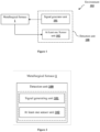
- the combination of the signal generating unit (101) and the at least one sensor unit (102) forms a detection unit (100) [as shown in Figure 2 ] for detecting crack propagation in the wall (2) of the metallurgical furnace (1).
- the signal generating unit (101) may be a mechanical signal generating unit, an electro-mechanical signal generating unit or an electronic signal generating unit, configured to transmit the stress signal into the wall (2).
- the signal generating unit (101) may be a mechanical signal generating unit such as a hammer, operated by striking an impact on the wall (2) by an operator for transmitting the stress signal into the wall (2).
- detection unit (100) may include only the at least one sensor unit (102) for capturing the reflected stress signal.
- the at least one sensor unit (102) is at least one of an active transducer or passive transducer, such as but not limiting to piezoelectric transducer, pressure transducer and the like.
- the stress signal is at least one of an analog signal, a digital signal or both, such as but not limiting to an acoustic signal, mechanical signal and the like which serves the requirement.
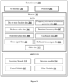
- Figure 3 in one exemplary embodiment of the present disclosure illustrates a block diagram of the detection unit (100) for detecting crack propagation in the wall (2) of the metallurgical furnace (1).
- the detection unit (100) comprises an I/O interface (301), a processor (302) and a memory (303).
- the memory (303) is communicatively coupled to the processor (302).
- the processor (302) is configured to perform one or more functions of the detection unit (100) for detecting crack propagation in the wall (2).
- the detection unit (100) comprises data and modules for performing various operations in accordance with the embodiments of the present disclosure.
- the data may include, without limiting to, one or more location data (304), frequency relevant to a thickness parameter data (305), thickness value data (306) dominant frequency data (307), predefined phase data (308), coefficient data (309), stress signal data (310), reflected stress signal data (311) and other data (312).
- the detection unit (100) may comprise a controller instead of the processor (302) for performing the functionalities of the detection unit (100) for detecting crack propagation in the wall (2).
- the data may be stored within the memory (303) in the form of various data structures. Additionally, the aforementioned data can be organized using data models, such as relational or hierarchical data models.
- the other data (312) may store data, including temporary data and temporary files, generated by modules for performing the various functions of the detection unit (100).
- the data may be processed by one or more modules.
- the one or more modules may also be stored as a part of the processor (302).
- the one or more modules may be communicatively coupled to the processor (302) for performing one or more functions of the detection unit (100).
- the one or more modules may include, without limiting to, receiving module (313), detection module (314), control module (315) and other modules (316).
- module refers to an application specific integrated circuit (ASIC), an electronic circuit, a processor (302) (shared, dedicated, or group) and memory (303) that execute one or more software or firmware programs, a combinational logic circuit, and/or other suitable components that provide the described functionality.
- ASIC application specific integrated circuit
- processor (302) shared, dedicated, or group
- memory (303) that execute one or more software or firmware programs, a combinational logic circuit, and/or other suitable components that provide the described functionality.
- the receiving module (313) may receive the one or more location data (304) from the detection unit (100) based on the location of the signal generating unit (101) through the I/O Interface (301).
- the receiving module (313) based on the one or more location data (304) determines the location of transmission of the stress signal into the wall (2).
- the one or more location data (304) is selected in a tuyere portion of the metallurgical furnace (1).
- the one or more location data (304) is selected along entire circumference of the metallurgical furnace (1).
- the receiving module (313) configured in the detection unit (100) may receive the frequency relevant to the thickness parameter data (305), computed by the detection unit (100) during detection of the crack propagation in the wall (2).
- the frequency relevant to the thickness parameter data (305) may represent a frequency relevant to thickness parameter (f t ) [shown in Figure 7d ], configured for measurement of the thickness value (t), based on the reflected stress signal. That is, the frequency relevant to the thickness parameter data (305) is the data pertaining to the frequency relevant to the thickness parameter (f t ) corresponding to the one or more dominant frequency parameters (f d ), which is obtained after a phase analysis of the reflected stress signal.
- the receiving module (313) configured to the detection unit (100) may receive the thickness value data (306), computed by the detection unit (100) during detection of the crack propagation in the wall (2).
- the thickness value data (306) may represent the thickness value (t) computed by the detection unit (100) based on the frequency relevant to thickness parameter data (305).
- each thickness value data (306) may provide the thickness value (t) for a plurality of layers (2a) of the wall (2).
- the receiving module (313) configured to the detection unit (100) may receive the dominant frequency data (307), extracted by the detection unit (100) during detection of the crack propagation in the wall (2).
- the dominant frequency data (307) may represent the frequency corresponding to the plurality of layers (2a) of the wall (2), extracted by the detection unit (100), from the reflected stress signal.
- the dominant frequency data (307) thus corresponds to the characteristic of each of the plurality of layers (2a) of the wall (2).
- the reflected stress signal may include three dominant frequency data [f d1 , f d2 and f d3 ], for each of the steel layer, the cooling layer and the carbon black layer in the reflected stress signal.
- the dominant frequency data (307) may enable the detection unit (100) to isolate the computed values, from the values computed for other dominant frequency data (307). Thus, enable the operator to emphasize on the readings necessary for detection of crack propagation in the wall (2).
- the receiving module (313) configured in the detection unit (100) may receive the predefined phase data (308), from the detection unit (100) during detection of the crack propagation in the wall (2).
- the predefined phase data (308) includes phase angle of a reference signal, which is superimposed on the reflected stress signal during computation of the frequency relevant to thickness parameter (ft).
- the predefined phase data (308) may include phase angle of the reference signal ranging from about 0 degrees to about 360 degrees.
- the receiving module (313) configured in the detection unit (100) may receive one or more coefficients (Y), computed by the detection unit (100) during detection of the crack propagation in the wall (2).
- the coefficient data (309) may represent an average amplitude parameter of a resultant signal obtained after super-imposing the reflected stress signal with the reference signal.
- the coefficient data (309) enables generation of the coefficient plot for determining the frequency relevant to the thickness parameter, thereby enabling determination of the thickness value (t) of the plurality of layers (2a) of the wall (2).
- the receiving module (313) configured in the detection unit (100) may receive the stress signal data (310), provided by the signal generating unit (101).
- the stress signal data (310) may include signal parameters such as, but not limiting to, frequency, amplitude, phase and the like, transmitted into the wall (2).
- the stress signal data (310) may enable the detection unit (100) to determine the signal parameters of the reflected stress signal.
- the receiving module (313) configured in the detection unit (100) may receive the reflected stress signal data (311), received by the at least one sensor unit (102).
- the reflected stress signal data (311) may include signal parameters such as, but not limiting to, frequency, amplitude, phase and the like, the reflected stress signal to enable the detection unit (100) to analyse the signal and determine crack propagation in the wall (2).
- the detection module (314) may detect crack propagation in the wall (2), based on the thickness value (t) determined by the detection unit (100) at the one or more locations (3).
- the detection module (314) may compute difference of the thickness value (t) of corresponding one or more dominant frequency parameters (f d ) at the one or more locations (3), for determination of the crack propagation in the wall (2).
- control module (315) may be configured to control operation of the detection unit (100) during detection of the crack propagation in the wall (2).
- Figure 4 in one exemplary embodiment of the present disclosure illustrates operation of the detection unit (100) for detecting crack propagation in the wall (2) of the metallurgical furnace (1).
- the operator may position the signal generating unit (101) at the one or more locations (3) for determining crack propagation in the wall (2).
- the operator may strike the one or more locations (3) using a hammer, for transmitting the stress signal into the wall (2).
- the stress signal propagates inside the wall (2), and is reflected back as the reflected stress signal.
- the operator may place the at least one sensor unit (102) adjacent to the one or more locations (3), for receiving the reflected stress signal based on the corresponding stress signal.
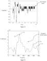
- the reflected stress signal received by the at least one sensor unit (102) is the time domain signal [as shown in Figure 7a ], which includes all the information pertaining to the composition, cracks, dislocations and the like of each of the plurality of layers (2a) of the wall (2).
- the reflected stress signal is transmitted to the detection unit (100) by the reflected stress signal for analysis and detection of the crack propagation.
- the detection unit (100) Upon receiving the reflected stress signal, the detection unit (100) converts the reflected stress signal from the time domain parameter to a frequency domain parameter.
- the detection unit (100) converts the reflected stress signal from the time domain parameter to the frequency domain parameter [as shown in Figure 7b ] by using Fast Fourier Transform [FFT] method.
- the reflected stress signal from the time domain parameter may be converted to the frequency domain parameter by the detection unit (100), by other analysis methods not limiting to Fast Fourier Transform [FFT].
- the reflected stress signal in the frequency domain parameter is configured to include one or more dominant frequency parameters (f d ) which is extracted by the detection unit (100) from each of the one or more locations (3).
- the number of one or more dominant frequency parameters (f d ) may correspond to number of the plurality of layers (2a) in the wall (2).
- the plurality of layers (2a) are three, the number of one or more dominant frequency parameter (f d ) would be three [fd 1 , fd 2 and fd 3 ].
- each of the one or more dominant frequency parameters (fd) may include characteristic such as thickness, cracks, undulations and the like of the corresponding layer in the plurality of layers (2a).
- characteristic such as thickness, cracks, undulations and the like of the corresponding layer in the plurality of layers (2a).
- the detection unit (100) is configured to analyze a phase of the one or more dominant frequency parameters (f d ) for a corresponding location of the one or more locations (3).
- the phase is determined by the detection unit (100), by firstly determining the one or more coefficients (Y) for each of the one or more dominant frequency parameters (f d ).
- the one or more coefficients (Y) are determined by modulating the reflected stress signal with a reference signal, wherein the reference signal is selected such that the frequency of the reference signal (f r ) [shown in Figure 7c ] matches with the each of the one or more dominant frequency parameters (f d ).
- the resultant signal due to the modulation results in an average amplitude signal yielding a corresponding coefficient of the one or more coefficients (Y).
- the reference signal is given by the below equation Eq. 1.
- Y sin ft + ⁇
- the corresponding coefficient of the one or more coefficients (Y) is determined.
- the computation is carried out by the detection unit (100), by incrementing the values of the one or more predefined phase values ( ⁇ ), for obtaining the corresponding coefficients of the one or more coefficients (Y).
- the one or more predefined phase values ( ⁇ ) ranges from about 0 degrees to about 360 degrees.
- the detection unit (100) Upon determining the one or more coefficients (Y), the detection unit (100) generates a coefficient plot [as shown in Figure 7d ] based on the one or more coefficients (Y) and the one or more predefined phase value ( ⁇ ).
- the coefficient plot is a sinusoidal curve.
- the detection unit (100), based on the coefficient plot identifies a dominant phase ( ⁇ d ) [as shown in Figure 7d ] of the corresponding one or more dominant frequency parameters (f d ).
- the peak values in the coefficient plot may represent the dominant phase ( ⁇ d ) of the corresponding one or more dominant frequency parameters (f d ).
- the detection unit (100) determines the frequency relevant to the thickness parameter based on the dominant phase ( ⁇ d ).
- the frequency relevant to the thickness parameter upon computation by the detection unit (100) determines the thickness value (t) for the corresponding one or more dominant frequency parameters (f d ).
- the thickness value (t) thus, represents thickness of the corresponding layer in the plurality of layers (2a).
- the thickness value (t) may be [ti, t 2 and t 3 ].
- the detection unit (100) performs the aforementioned method for each of the one or more locations (3), and consequently determines the thickness value (t) for each of the plurality of layers (2a).
- the detection unit (100) compares the thickness value (t) obtained for the corresponding plurality of layers (2a) for determining crack propagation in the wall (2) of the metallurgical furnace (1).
- the detection unit (100) computes difference between these values, and since for the same layer includes variations in the value computed, the detection unit (100) detects that crack is propagating in that layer of the plurality of layers (2a).
- the detection unit (100) provides a warning signal or an alert to the user, upon determination of crack propagation in the wall (2) of the metallurgical furnace (1).
- analysis of the phase is carried out by phase shift method.
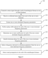
- Figure 5 in one exemplary embodiment of the present disclosure illustrates a flowchart of a method for detecting crack propagation by the detection unit (100).
- the signal generating unit (101) located at the one or more locations (3) transmits the stress signal into the wall (2) at the one or more locations (3).
- the signal generating unit (101) is the hammer, wherein the operator strikes the wall (2) manually to transmit the stress signal into the wall (2), wherein the stress signal is the acoustic sound signal.
- the signal generating unit (101) may be operated manually by the operator for transmitting the stress signal.
- the signal generating unit (101) may be automatically operated after placing at each of the one or more locations (3), for transmitting the stress signal.
- the stress signal propagates within the wall (2) and is reflected back as the reflected stress signal.
- the reflected stress signal from each of the one or more locations (3) is received by the at least one sensor unit (102).
- the at least one sensor unit (102) is positioned adjacent to the signal generating unit (101), for receiving the reflected stress signal.
- the at least one sensor unit (102) may be configured to receive the reflected stress signal from each of the one or more locations (3) from a single location.
- the detection unit (100) is configured to extract the one or more dominant frequency parameters (f d ) from the reflected stress signal.
- the detection unit (100) converts the reflected stress signal in the time domain parameter as received by the at least one sensor unit (102), into the frequency domain parameter.
- the time domain signal By conversion of the time domain signal to the frequency domain signal, the values pertaining to each of the plurality of layers (2a) of the wall (2) are segregated. Since segregation of required parameters based on time domain parameter would be cumbersome and will generally be associated with noise or unwanted signals.
- the reflected stress signal in the frequency domain parameter includes one or more dominant frequency parameters (f d ), which corresponds to frequencies of each of the plurality of layers (2a) of the wall (2).
- the detection unit (100) extracts the one or more dominant frequency parameters (f d ) from the reflected stress signal in the frequency domain parameter.
- the detection unit (100) detects the phase of each of the one or more dominant frequency parameters (f d ). For detecting the phase, the detection unit (100) modulates the reflected stress signal with the reference signal based on the one or more predefined phase values ( ⁇ ), wherein the reference signal is configured with the corresponding one or more dominant frequency parameters (f d ). The modulation provides the coefficient of the one or more coefficients (Y) corresponding to the phase value [as referred in block 505]. The detection unit (100) performs computation of the one or more coefficients (Y) for each value of the one or more predefined phase values ( ⁇ ). The one or more coefficients (Y) are then plotted, to generate the coefficient plot.
- the peak value of the coefficient plot determines the phase of the corresponding one or more dominant frequency parameters (f d ).
- the determined phase is the dominant phase ( ⁇ d ) of the corresponding one or more dominant frequency parameters (f d ) [as referred in block 506].
- the detection unit (100) determines the frequency relevant to thickness parameter (f t ) based on the dominant phase ( ⁇ d ).
- the frequency relevant to thickness parameter (f t ) upon computation by the detection unit (100), provides the thickness value (t) for the corresponding one or more dominant frequency parameters (f d ).
- the detection unit (100) subsequently computed the thickness value (t) for other locations of the one or more locations (3), corresponding to the one or more dominant frequency.
- the detection unit (100) compares the thickness value (t) of the corresponding one or more dominant frequency parameters (f d ). During comparison, when the detection unit (100) detects variation in the thickness value (t) for the corresponding one or more dominant frequency parameters (f d ), the detection unit (100) detects crack propagation in the wall (2).
- Figure 8 in one exemplary embodiment of the present disclosure illustrates a block (501) diagram of a computer system (800) for implementing embodiments consistent with the present disclosure.
- the computer system (800) can be the detection unit (100) configured detecting crack propagation in the wall (2) of the metallurgical furnace (1).
- the computer system (800) may comprise a central processing unit (“CPU” or "processor") 802.
- the processor (802) may comprise at least one data processor for executing program components for executing user- or system-generated processes.
- the processor may include specialized processing units such as integrated system (bus) controllers, memory management control units, floating point units, graphics processing units, digital signal processing units, etc.
- the processor (802) may be disposed in communication with one or more input/output (I/O) devices (811 and 812) via an I/O interface (801).
- the I/O interface (801) may employ communication protocols/methods such as, without limitation, audio, analog, digital, stereo, ieee (802)-1394, serial bus, Universal Serial Bus (USB), infrared, PS/2, BNC, coaxial, component, composite, Digital Visual Interface (DVI), high-definition multimedia interface (HDMI), Radio Frequency (RF) antennas, S-Video, Video Graphics Array (VGA), IEEE 802.n /b/g/n/x, Bluetooth, cellular (e.g., Code-Division Multiple Access (CDMA), High-Speed Packet Access (HSPA+), Global System For Mobile Communications (GSM), Long-Term Evolution (LTE) or the like), etc.
- CDMA Code-Division Multiple Access
- HSPA+ High-Speed Packet Access
- GSM Global System For Mobile Communications
- the computer system (800) may communicate with the one or more I/O devices (811 and 812).
- the processor (802) may be disposed in communication with a communication network (809) via a network interface (803).
- the network interface (803) may communicate with the communication network (809).
- the network interface (803) may employ connection protocols including, without limitation, direct connect, Ethernet (e.g., twisted pair 10/100/1000 Base T), Transmission Control Protocol/Internet Protocol (TCP/IP), token ring, IEEE 802.11a/b/g/n/x, etc.
- the communication network (809) can be implemented as one of the different types of networks, such as intranet or Local Area Network (LAN) and such within the organization.
- LAN Local Area Network
- the communication network (809) may either be a dedicated network or a shared network, which represents an association of the different types of networks that use a variety of protocols, for example, Hypertext Transfer Protocol (HTTP), Transmission Control Protocol/Internet Protocol (TCP/IP), Wireless Application Protocol (WAP), etc., to communicate with each other. Further, the communication network (809) may include a variety of network devices (811), including routers, bridges, servers, computing devices (811), storage devices (811), etc.
- HTTP Hypertext Transfer Protocol
- TCP/IP Transmission Control Protocol/Internet Protocol
- WAP Wireless Application Protocol
- the communication network (809) may include a variety of network devices (811), including routers, bridges, servers, computing devices (811), storage devices (811), etc.
- the processor may be disposed in communication with a memory (805) (e.g., RAM 813, ROM 814, etc.) via a storage interface.
- the storage interface (804) may connect to memory including, without limitation, memory drives, removable disc drives, etc., employing connection protocols such as Serial Advanced Technology Attachment (SATA), Integrated Drive Electronics (IDE), ieee-1394, Universal Serial Bus (USB), fiber channel, Small Computer Systems Interface (SCSI), etc.
- the memory drives may further include a drum, magnetic disc drive, magneto-optical drive, optical drive, Redundant Array of Independent Discs (RAID), solid-state memory devices, solid-state drives, etc.
- the memory may store a collection of program or database components, including, without limitation, user/application data, an operating system, web browser etc.
- computer system may store user/application data, such as the data, variables, records, etc. as described in this disclosure.
- databases may be implemented as fault-tolerant, relational, scalable, secure databases such as Oracle or Sybase.
- a computer-readable storage medium refers to any type of physical memory on which information or data readable by a processor may be stored.
- a computer-readable storage medium may store instructions for execution by one or more processors, including instructions for causing the processor(s) to perform steps or stages consistent with the embodiments described herein.
- the term "computer-readable medium” should be understood to include tangible items and exclude carrier waves and transient signals, i.e., non-transitory. Examples include Random Access memory (ram), Read-Only memory (rom), volatile memory, non-volatile memory, hard drives, Compact Disc (CD) ROMs, Digital Video Disc (DVDs), flash drives, disks, and any other known physical storage media.
- the present disclosure provides a method for determining crack propagation in the wall of the metallurgical vessel by filtering unwanted or by noise signal cancellation. Thereby, improving accuracy of the readings obtained.
- the present disclosure provides the method for determining thickness of each of the plurality of layers in the wall, separately.
- the present disclosure provides the method for accurately determining condition of the refractory lining of the metallurgical furnace.
- Referral Numerals Description 100 Detection unit 101
- Signal generating unit 102 At least one sensor unit 103 Environment 1
- Memory 304 One or more location data 305 frequency relevant to thickness parameter data 306
- Thickness value data 307
- Dominant frequency data 308
- Predefined phase data Predefined phase data 309
- Coefficient data 310 Stress signal data 311 Reflected tress signal data 312 Other data 313
- Receiving module 314 Detection module 315
- Control module 316 Other modules f r Frequency of the reference signal t
- Thickness value f d One or more dominant frequency parameters
- Y One or more coefficients ⁇
Landscapes
- Engineering & Computer Science (AREA)
- Physics & Mathematics (AREA)
- Chemical & Material Sciences (AREA)
- General Health & Medical Sciences (AREA)
- Immunology (AREA)
- Health & Medical Sciences (AREA)
- Life Sciences & Earth Sciences (AREA)
- Pathology (AREA)
- Analytical Chemistry (AREA)
- Biochemistry (AREA)
- General Physics & Mathematics (AREA)
- Mechanical Engineering (AREA)
- General Engineering & Computer Science (AREA)
- Signal Processing (AREA)
- Acoustics & Sound (AREA)
- Mathematical Physics (AREA)
- Spectroscopy & Molecular Physics (AREA)
- Manufacturing & Machinery (AREA)
- Materials Engineering (AREA)
- Metallurgy (AREA)
- Organic Chemistry (AREA)
- Waste-Gas Treatment And Other Accessory Devices For Furnaces (AREA)
- Investigating Or Analyzing Materials By The Use Of Ultrasonic Waves (AREA)
Description
- Present invention relates to a method of detecting crack propagation in a wall of a metallurgical furnace and a detection unit for detecting crack propagation in the wall of the metallurgical furnace.
- Metallurgical furnace such as, but not limiting to, blast furnaces are used for extraction of metals from raw materials. Typically, these metallurgical furnaces include a multilayer sidewall having an inner layer and an outer layer. The outer layer is usually a steel structural support and the inner layer includes a refractory lining consisting of one or more layers of refractory bricks or carbon blocks. In certain furnaces, a cooling layer may be provided between the inner layer and the outer layer as insulation, to prevent transfer of heat from the refractory lining to the outer layer.
- During operation of the metallurgical furnace, the refractory lining is subjected to mechanical and thermal stresses due to heat generated within the metallurgical furnace. Additionally, a tuyere region of the metallurgical furnace comprising an inner most layer of the refractory lining is subjected to wear, due to relative motion of hot metal. These stresses along with wear, results in reduced overall thickness of the refractory lining, which is undesirable. Further, damage to the refractory lining results in a structural failure, which may lead to the outer layer being exposed to corrosive chemicals and molten material. Further, the outer layer would be incapable of containing the molten material and the corrosive chemicals, once the refractory lining is damaged. This leads to, the molten material and the corrosive chemicals leaking from the metallurgical furnace, which is hazardous and undesirable.
- Conventionally, to overcome such limitations in the refractory lining, various systems for measuring thickness of refractory lining are employed. The systems generally operate based on non-destructive testing techniques, since the refractory lining is inaccessible to an operator from the inside of the blast furnace. The systems to determine the thickness of the refractory lining generally include, a plurality of thermocouples provided at predetermined locations in the wall of the metallurgical furnace. The plurality of thermocouples is configured to monitor the temperatures at each location in the wall. When a sudden increase in temperature is detected, the plurality of thermocouples provides warning signals to the operator for necessary precautionary measures. Though, this system provides warning signals upon detecting sudden increase in temperature, the system provides estimate readings pertaining to refractory lining as well as that of the other layers in the metallurgical furnace. Additionally, mounting these sensors in the wall of the metallurgical furnace is cumbersome and expensive.
- Another system employed for measurement of the thickness of the wall of the metallurgical furnace, would be an acousto-ultrasonic technique. The technique involves using a transient propagated stress wave for determining condition of the refractory lining. The technique works based on the effect of velocity of the stress wave through a heated refractory lining. This system provides details pertaining to condition of the wall, and prevents need for providing plurality of thermocouples. However, this system interprets data of the stress wave such that, all the frequencies relate to the refractory lining or the carbon block. Thus, this procedure includes risk of misinterpreting the noise frequency, i.e. frequency which is not related to the refractory lining or the carbon block for knowing condition of the carbon block, leading to inaccurate measurements, which is undesirable.
- Thus, there exists a need for a method of determining crack propagation in the wall of the metallurgical furnace, for accurate assertion of condition of the wall of the metallurgical furnace.
- A system, method and apparatus for inspecting a metallurgical furnace wall is known from
US 2008/092658 A1 . Furthermore, the publication of A. Sadri et al.: "A Comprehensive Review of Acousto Ultrasonic-Echo (AU-E) Technique for Furnace Refractory Lining Assessment" on the Conference of Metallurgists in 2015 discloses a method for monitoring the refractory lining integrity, thereby determining the remaining life of a furnace. - The information disclosed in this background of the disclosure section is only for enhancement of understanding of the general background of the invention.
- The scope of the present invention is defined by
independent claims - The invention itself as well as a preferred mode of use, further objectives and advantages thereof, will best be understood by reference to the following detailed description of an illustrative embodiment when read in conjunction with the accompanying figures. One or more embodiments are now described, by way of example only, with reference to the accompanying figures wherein like reference numerals represent like elements and in which:
-
Figure 1 illustrates a schematic view of a detection unit associated with a metallurgical furnace for detecting crack propagation in a wall of the metallurgical furnace, in accordance with an embodiment of the present disclosure. -
Figure 2 illustrates a block diagram of the detection unit ofFigure 1 , in accordance with an embodiment of the present disclosure. -
Figure 3 illustrates another block diagram of the detection unit configured for detecting crack propagation in the wall, in accordance with an embodiment of the present disclosure. -
Figure 4 illustrates a schematic view of the metallurgical furnace, with a stress signal being transmitted by an operator, in accordance with an embodiment of the present disclosure. -
Figure 5 illustrates a flow chart for detecting crack propagation in the wall, in accordance with an embodiment of the present disclosure. -
Figure 6 illustrates a flow chart for computing thickness values for detecting crack propagation in the wall, in accordance with an embodiment of the present disclosure. -
Figure 7a illustrates a graphical representation of a reflected stress signal in time domain parameter, in accordance with an embodiment of the present disclosure. -
Figure 7b illustrates a graphical representation of the reflected stress signal converted to a frequency domain parameter, in accordance with an embodiment of the present disclosure. -
Figure 7c illustrates a graphical representation of the reflected stress signal modulated to a phase domain, in accordance with an embodiment of the present disclosure. -
Figure 7d illustrates a graphical representation of a coefficient plot obtained after modulating the reflected stress signal, in accordance with an embodiment of the present disclosure. -
Figure 8 illustrates a block diagram of an exemplary computer system for implementing embodiments consistent with the present disclosure. - The figures depict embodiments of the disclosure for purposes of illustration only.
- Embodiments of the present disclosure provides a method and a detection unit for determining crack propagation in a wall of a metallurgical furnace. The method is configured to compute characteristic details pertaining to refractory lining of the metallurgical furnace such as but not limiting to a thickness value. The method is configured to filter out irrelevant data such as a noise signal, to obtain an accurate estimate of the condition of the wall of the metallurgical furnace.
-
Figure 1 in one exemplary embodiment of the present disclosure illustrates an environment (103) for determining crack propagation in a wall (2) of a metallurgical furnace (1). The environment (103) is configured to include various components that may be common to any metallurgical industries, where the metallurgical furnace (1) is operated. In the present disclosure, the crack propagation in the wall (2) of the metallurgical furnace (1) is detected based on a phase shift analysis of a stress signal transmitted through the wall (2). - The environment (103) comprises a signal generating unit (101) and at least one sensor unit (102). The signal generating unit (101) is configured to transmit the stress signal into the wall (2) of the metallurgical furnace (1) at one or more locations (3) [shown in
Figure 4 ]. The stress signal propagates into the wall (2), and is reflected back as a reflected stress signal. The reflected stress signal is received by the at least one sensor unit (102), which may be placed adjacent to the point of transmission of the stress signal on the wall (2). The at least one sensor unit (102), may transmit the reflected stress signal to a control unit or a processor for further analysis of the reflected stress signal. The combination of the signal generating unit (101) and the at least one sensor unit (102) forms a detection unit (100) [as shown inFigure 2 ] for detecting crack propagation in the wall (2) of the metallurgical furnace (1). - In an embodiment, the signal generating unit (101) may be a mechanical signal generating unit, an electro-mechanical signal generating unit or an electronic signal generating unit, configured to transmit the stress signal into the wall (2). In an embodiment, and for the sake of simplicity, the signal generating unit (101) may be a mechanical signal generating unit such as a hammer, operated by striking an impact on the wall (2) by an operator for transmitting the stress signal into the wall (2). In one embodiment, if the signal generating unit (101) is mechanical signal generating unit, then detection unit (100) may include only the at least one sensor unit (102) for capturing the reflected stress signal.
- In an embodiment, the at least one sensor unit (102) is at least one of an active transducer or passive transducer, such as but not limiting to piezoelectric transducer, pressure transducer and the like.
- In an embodiment, the stress signal is at least one of an analog signal, a digital signal or both, such as but not limiting to an acoustic signal, mechanical signal and the like which serves the requirement.
-
Figure 3 in one exemplary embodiment of the present disclosure illustrates a block diagram of the detection unit (100) for detecting crack propagation in the wall (2) of the metallurgical furnace (1). In the present invention, the detection unit (100) comprises an I/O interface (301), a processor (302) and a memory (303). The memory (303) is communicatively coupled to the processor (302). The processor (302) is configured to perform one or more functions of the detection unit (100) for detecting crack propagation in the wall (2). In one implementation, the detection unit (100) comprises data and modules for performing various operations in accordance with the embodiments of the present disclosure. In an embodiment, the data may include, without limiting to, one or more location data (304), frequency relevant to a thickness parameter data (305), thickness value data (306) dominant frequency data (307), predefined phase data (308), coefficient data (309), stress signal data (310), reflected stress signal data (311) and other data (312). - In an embodiment, the detection unit (100) may comprise a controller instead of the processor (302) for performing the functionalities of the detection unit (100) for detecting crack propagation in the wall (2).
- In one embodiment, the data may be stored within the memory (303) in the form of various data structures. Additionally, the aforementioned data can be organized using data models, such as relational or hierarchical data models. The other data (312) may store data, including temporary data and temporary files, generated by modules for performing the various functions of the detection unit (100).
- In an embodiment, the data may be processed by one or more modules. In one implementation, the one or more modules may also be stored as a part of the processor (302). In an example, the one or more modules may be communicatively coupled to the processor (302) for performing one or more functions of the detection unit (100).
- In one implementation, the one or more modules may include, without limiting to, receiving module (313), detection module (314), control module (315) and other modules (316).
- As used herein, the term module refers to an application specific integrated circuit (ASIC), an electronic circuit, a processor (302) (shared, dedicated, or group) and memory (303) that execute one or more software or firmware programs, a combinational logic circuit, and/or other suitable components that provide the described functionality.
- In an embodiment, the receiving module (313) may receive the one or more location data (304) from the detection unit (100) based on the location of the signal generating unit (101) through the I/O Interface (301). The receiving module (313) based on the one or more location data (304) determines the location of transmission of the stress signal into the wall (2). In an embodiment, the one or more location data (304) is selected in a tuyere portion of the metallurgical furnace (1). In an embodiment, the one or more location data (304) is selected along entire circumference of the metallurgical furnace (1).
- In an embodiment, the receiving module (313) configured in the detection unit (100) may receive the frequency relevant to the thickness parameter data (305), computed by the detection unit (100) during detection of the crack propagation in the wall (2). The frequency relevant to the thickness parameter data (305) may represent a frequency relevant to thickness parameter (ft) [shown in
Figure 7d ], configured for measurement of the thickness value (t), based on the reflected stress signal. That is, the frequency relevant to the thickness parameter data (305) is the data pertaining to the frequency relevant to the thickness parameter (ft) corresponding to the one or more dominant frequency parameters (fd), which is obtained after a phase analysis of the reflected stress signal. - In an embodiment, the receiving module (313) configured to the detection unit (100) may receive the thickness value data (306), computed by the detection unit (100) during detection of the crack propagation in the wall (2). The thickness value data (306) may represent the thickness value (t) computed by the detection unit (100) based on the frequency relevant to thickness parameter data (305). In an embodiment, each thickness value data (306) may provide the thickness value (t) for a plurality of layers (2a) of the wall (2).
- In an embodiment, the receiving module (313) configured to the detection unit (100) may receive the dominant frequency data (307), extracted by the detection unit (100) during detection of the crack propagation in the wall (2). The dominant frequency data (307) may represent the frequency corresponding to the plurality of layers (2a) of the wall (2), extracted by the detection unit (100), from the reflected stress signal. The dominant frequency data (307) thus corresponds to the characteristic of each of the plurality of layers (2a) of the wall (2). In an exemplary embodiment, if the plurality of layers (2a) includes a steel layer, a cooling layer and a carbon black layer, the reflected stress signal may include three dominant frequency data [fd1, fd2 and fd3], for each of the steel layer, the cooling layer and the carbon black layer in the reflected stress signal. The dominant frequency data (307) may enable the detection unit (100) to isolate the computed values, from the values computed for other dominant frequency data (307). Thus, enable the operator to emphasize on the readings necessary for detection of crack propagation in the wall (2).
- In an embodiment, the receiving module (313) configured in the detection unit (100) may receive the predefined phase data (308), from the detection unit (100) during detection of the crack propagation in the wall (2). The predefined phase data (308) includes phase angle of a reference signal, which is superimposed on the reflected stress signal during computation of the frequency relevant to thickness parameter (ft). The predefined phase data (308) may include phase angle of the reference signal ranging from about 0 degrees to about 360 degrees.
- In an embodiment, the receiving module (313) configured in the detection unit (100) may receive one or more coefficients (Y), computed by the detection unit (100) during detection of the crack propagation in the wall (2). The coefficient data (309) may represent an average amplitude parameter of a resultant signal obtained after super-imposing the reflected stress signal with the reference signal. The coefficient data (309) enables generation of the coefficient plot for determining the frequency relevant to the thickness parameter, thereby enabling determination of the thickness value (t) of the plurality of layers (2a) of the wall (2).
- In an embodiment, the receiving module (313) configured in the detection unit (100) may receive the stress signal data (310), provided by the signal generating unit (101). The stress signal data (310) may include signal parameters such as, but not limiting to, frequency, amplitude, phase and the like, transmitted into the wall (2). The stress signal data (310) may enable the detection unit (100) to determine the signal parameters of the reflected stress signal.
- In an embodiment, the receiving module (313) configured in the detection unit (100) may receive the reflected stress signal data (311), received by the at least one sensor unit (102).
- The reflected stress signal data (311) may include signal parameters such as, but not limiting to, frequency, amplitude, phase and the like, the reflected stress signal to enable the detection unit (100) to analyse the signal and determine crack propagation in the wall (2).
- In an embodiment, the detection module (314) may detect crack propagation in the wall (2), based on the thickness value (t) determined by the detection unit (100) at the one or more locations (3). The detection module (314) may compute difference of the thickness value (t) of corresponding one or more dominant frequency parameters (fd) at the one or more locations (3), for determination of the crack propagation in the wall (2).
- In an embodiment, the control module (315) may be configured to control operation of the detection unit (100) during detection of the crack propagation in the wall (2).
-
Figure 4 in one exemplary embodiment of the present disclosure illustrates operation of the detection unit (100) for detecting crack propagation in the wall (2) of the metallurgical furnace (1). - The operator may position the signal generating unit (101) at the one or more locations (3) for determining crack propagation in the wall (2). The operator may strike the one or more locations (3) using a hammer, for transmitting the stress signal into the wall (2). The stress signal propagates inside the wall (2), and is reflected back as the reflected stress signal. Subsequently, the operator may place the at least one sensor unit (102) adjacent to the one or more locations (3), for receiving the reflected stress signal based on the corresponding stress signal. The reflected stress signal received by the at least one sensor unit (102) is the time domain signal [as shown in
Figure 7a ], which includes all the information pertaining to the composition, cracks, dislocations and the like of each of the plurality of layers (2a) of the wall (2). The reflected stress signal is transmitted to the detection unit (100) by the reflected stress signal for analysis and detection of the crack propagation. - Upon receiving the reflected stress signal, the detection unit (100) converts the reflected stress signal from the time domain parameter to a frequency domain parameter. The detection unit (100) converts the reflected stress signal from the time domain parameter to the frequency domain parameter [as shown in
Figure 7b ] by using Fast Fourier Transform [FFT] method. In an embodiment, the reflected stress signal from the time domain parameter may be converted to the frequency domain parameter by the detection unit (100), by other analysis methods not limiting to Fast Fourier Transform [FFT]. The reflected stress signal in the frequency domain parameter is configured to include one or more dominant frequency parameters (fd) which is extracted by the detection unit (100) from each of the one or more locations (3). In an embodiment, the number of one or more dominant frequency parameters (fd) may correspond to number of the plurality of layers (2a) in the wall (2). As an example, the plurality of layers (2a) are three, the number of one or more dominant frequency parameter (fd) would be three [fd1, fd2 and fd3]. - In an embodiment, each of the one or more dominant frequency parameters (fd) may include characteristic such as thickness, cracks, undulations and the like of the corresponding layer in the plurality of layers (2a). Thus, considering one of the one or more dominant frequency parameter (fd) corresponds to measurement of characteristics of the corresponding layer of the plurality of layers (2a).
- Subsequently, the detection unit (100) is configured to analyze a phase of the one or more dominant frequency parameters (fd) for a corresponding location of the one or more locations (3). The phase is determined by the detection unit (100), by firstly determining the one or more coefficients (Y) for each of the one or more dominant frequency parameters (fd). The one or more coefficients (Y) are determined by modulating the reflected stress signal with a reference signal, wherein the reference signal is selected such that the frequency of the reference signal (fr) [shown in
Figure 7c ] matches with the each of the one or more dominant frequency parameters (fd). The resultant signal due to the modulation, results in an average amplitude signal yielding a corresponding coefficient of the one or more coefficients (Y). - In an embodiment, the reference signal is given by the below equation Eq. 1.

- Wherein,
- Y may be the one or more coefficients;
- f may be the frequency of the reference signal, equal to each of the one or more dominant frequency parameters (fd);
- t may be a time parameter;
- Ø may be one or more predefined phase values.
- By computing the above Eq. 1, with the known values and with the one or more predefined phase values (Ø), the corresponding coefficient of the one or more coefficients (Y) is determined. The computation is carried out by the detection unit (100), by incrementing the values of the one or more predefined phase values (Ø), for obtaining the corresponding coefficients of the one or more coefficients (Y). In an embodiment, the one or more predefined phase values (Ø) ranges from about 0 degrees to about 360 degrees.
- In an exemplary embodiment, if Yi is the corresponding coefficient obtained for the phase value of Ø1, then for Ø2 the corresponding coefficient would be Y2. In other words, for Ø[1-360] the corresponding coefficients of the one or more coefficients (Y) would be Y[1-360].
- Upon determining the one or more coefficients (Y), the detection unit (100) generates a coefficient plot [as shown in
Figure 7d ] based on the one or more coefficients (Y) and the one or more predefined phase value (Ø). In an embodiment, the coefficient plot is a sinusoidal curve. The detection unit (100), based on the coefficient plot identifies a dominant phase (Ød) [as shown inFigure 7d ] of the corresponding one or more dominant frequency parameters (fd). In an embodiment, the peak values in the coefficient plot may represent the dominant phase (Ød) of the corresponding one or more dominant frequency parameters (fd). Subsequently, the detection unit (100) determines the frequency relevant to the thickness parameter based on the dominant phase (Ød). The frequency relevant to the thickness parameter upon computation by the detection unit (100), determines the thickness value (t) for the corresponding one or more dominant frequency parameters (fd). As, each of the one or more dominant frequency parameters (fd) corresponds to each of the plurality of layers (2a), the thickness value (t) thus, represents thickness of the corresponding layer in the plurality of layers (2a). In an embodiment, for the wall (2) having the three layers, the thickness value (t) may be [ti, t2 and t3]. - Subsequently, the detection unit (100), performs the aforementioned method for each of the one or more locations (3), and consequently determines the thickness value (t) for each of the plurality of layers (2a). The detection unit (100), compares the thickness value (t) obtained for the corresponding plurality of layers (2a) for determining crack propagation in the wall (2) of the metallurgical furnace (1).
- In an exemplary embodiment, consider the thickness value (t) obtained for carbon block is 0.4m at one location of the one or more locations (3) and the thickness value (t) is 0.2m at another location. The detection unit (100) computes difference between these values, and since for the same layer includes variations in the value computed, the detection unit (100) detects that crack is propagating in that layer of the plurality of layers (2a).
- In an embodiment, the detection unit (100), provides a warning signal or an alert to the user, upon determination of crack propagation in the wall (2) of the metallurgical furnace (1).
- In an embodiment, analysis of the phase is carried out by phase shift method.
-
Figure 5 in one exemplary embodiment of the present disclosure illustrates a flowchart of a method for detecting crack propagation by the detection unit (100). - At
block 501, the signal generating unit (101) located at the one or more locations (3), transmits the stress signal into the wall (2) at the one or more locations (3). In an exemplary embodiment, the signal generating unit (101) is the hammer, wherein the operator strikes the wall (2) manually to transmit the stress signal into the wall (2), wherein the stress signal is the acoustic sound signal. In an embodiment, the signal generating unit (101) may be operated manually by the operator for transmitting the stress signal. In another embodiment, the signal generating unit (101) may be automatically operated after placing at each of the one or more locations (3), for transmitting the stress signal. - At
block 502, the stress signal propagates within the wall (2) and is reflected back as the reflected stress signal. The reflected stress signal from each of the one or more locations (3) is received by the at least one sensor unit (102). The at least one sensor unit (102) is positioned adjacent to the signal generating unit (101), for receiving the reflected stress signal. In an embodiment, the at least one sensor unit (102) may be configured to receive the reflected stress signal from each of the one or more locations (3) from a single location. - At
block 503, the detection unit (100) is configured to extract the one or more dominant frequency parameters (fd) from the reflected stress signal. For extracting the one or more dominant frequency parameters (fd), the detection unit (100), converts the reflected stress signal in the time domain parameter as received by the at least one sensor unit (102), into the frequency domain parameter. By conversion of the time domain signal to the frequency domain signal, the values pertaining to each of the plurality of layers (2a) of the wall (2) are segregated. Since segregation of required parameters based on time domain parameter would be cumbersome and will generally be associated with noise or unwanted signals. The reflected stress signal in the frequency domain parameter includes one or more dominant frequency parameters (fd), which corresponds to frequencies of each of the plurality of layers (2a) of the wall (2). The detection unit (100), extracts the one or more dominant frequency parameters (fd) from the reflected stress signal in the frequency domain parameter. - At
block 504, the detection unit (100), detects the phase of each of the one or more dominant frequency parameters (fd). For detecting the phase, the detection unit (100) modulates the reflected stress signal with the reference signal based on the one or more predefined phase values (Ø), wherein the reference signal is configured with the corresponding one or more dominant frequency parameters (fd). The modulation provides the coefficient of the one or more coefficients (Y) corresponding to the phase value [as referred in block 505]. The detection unit (100) performs computation of the one or more coefficients (Y) for each value of the one or more predefined phase values (Ø). The one or more coefficients (Y) are then plotted, to generate the coefficient plot. The peak value of the coefficient plot determines the phase of the corresponding one or more dominant frequency parameters (fd). The determined phase is the dominant phase (Ød) of the corresponding one or more dominant frequency parameters (fd) [as referred in block 506]. - At
block 507, in conjunction withblock 601 ofFigure 6 , the detection unit (100) determines the frequency relevant to thickness parameter (ft) based on the dominant phase (Ød). The frequency relevant to thickness parameter (ft), upon computation by the detection unit (100), provides the thickness value (t) for the corresponding one or more dominant frequency parameters (fd). The detection unit (100) subsequently computed the thickness value (t) for other locations of the one or more locations (3), corresponding to the one or more dominant frequency. - At
block 508, in conjunction withblock 602 ofFigure 6 , the detection unit (100), compares the thickness value (t) of the corresponding one or more dominant frequency parameters (fd). During comparison, when the detection unit (100) detects variation in the thickness value (t) for the corresponding one or more dominant frequency parameters (fd), the detection unit (100) detects crack propagation in the wall (2). -
Figure 8 in one exemplary embodiment of the present disclosure illustrates a block (501) diagram of a computer system (800) for implementing embodiments consistent with the present disclosure. In an embodiment, the computer system (800) can be the detection unit (100) configured detecting crack propagation in the wall (2) of the metallurgical furnace (1). The computer system (800) may comprise a central processing unit ("CPU" or "processor") 802. The processor (802) may comprise at least one data processor for executing program components for executing user- or system-generated processes. The processor may include specialized processing units such as integrated system (bus) controllers, memory management control units, floating point units, graphics processing units, digital signal processing units, etc. - The processor (802) may be disposed in communication with one or more input/output (I/O) devices (811 and 812) via an I/O interface (801). The I/O interface (801) may employ communication protocols/methods such as, without limitation, audio, analog, digital, stereo, ieee (802)-1394, serial bus, Universal Serial Bus (USB), infrared, PS/2, BNC, coaxial, component, composite, Digital Visual Interface (DVI), high-definition multimedia interface (HDMI), Radio Frequency (RF) antennas, S-Video, Video Graphics Array (VGA), IEEE 802.n /b/g/n/x, Bluetooth, cellular (e.g., Code-Division Multiple Access (CDMA), High-Speed Packet Access (HSPA+), Global System For Mobile Communications (GSM), Long-Term Evolution (LTE) or the like), etc.
- Using the I/O interface (801), the computer system (800) may communicate with the one or more I/O devices (811 and 812).
- In an embodiment, the processor (802) may be disposed in communication with a communication network (809) via a network interface (803). The network interface (803) may communicate with the communication network (809). The network interface (803) may employ connection protocols including, without limitation, direct connect, Ethernet (e.g., twisted
pair 10/100/1000 Base T), Transmission Control Protocol/Internet Protocol (TCP/IP), token ring, IEEE 802.11a/b/g/n/x, etc. The communication network (809) can be implemented as one of the different types of networks, such as intranet or Local Area Network (LAN) and such within the organization. The communication network (809) may either be a dedicated network or a shared network, which represents an association of the different types of networks that use a variety of protocols, for example, Hypertext Transfer Protocol (HTTP), Transmission Control Protocol/Internet Protocol (TCP/IP), Wireless Application Protocol (WAP), etc., to communicate with each other. Further, the communication network (809) may include a variety of network devices (811), including routers, bridges, servers, computing devices (811), storage devices (811), etc. - In an embodiment, the processor may be disposed in communication with a memory (805) (e.g.,
RAM 813,ROM 814, etc.) via a storage interface. The storage interface (804) may connect to memory including, without limitation, memory drives, removable disc drives, etc., employing connection protocols such as Serial Advanced Technology Attachment (SATA), Integrated Drive Electronics (IDE), ieee-1394, Universal Serial Bus (USB), fiber channel, Small Computer Systems Interface (SCSI), etc. The memory drives may further include a drum, magnetic disc drive, magneto-optical drive, optical drive, Redundant Array of Independent Discs (RAID), solid-state memory devices, solid-state drives, etc. - The memory may store a collection of program or database components, including, without limitation, user/application data, an operating system, web browser etc. In some embodiments, computer system may store user/application data, such as the data, variables, records, etc. as described in this disclosure. Such databases may be implemented as fault-tolerant, relational, scalable, secure databases such as Oracle or Sybase.
- Furthermore, one or more computer-readable storage media may be utilized in implementing embodiments consistent with the present disclosure. A computer-readable storage medium refers to any type of physical memory on which information or data readable by a processor may be stored. Thus, a computer-readable storage medium may store instructions for execution by one or more processors, including instructions for causing the processor(s) to perform steps or stages consistent with the embodiments described herein. The term "computer-readable medium" should be understood to include tangible items and exclude carrier waves and transient signals, i.e., non-transitory. Examples include Random Access memory (ram), Read-Only memory (rom), volatile memory, non-volatile memory, hard drives, Compact Disc (CD) ROMs, Digital Video Disc (DVDs), flash drives, disks, and any other known physical storage media.
- In an embodiment, the present disclosure provides a method for determining crack propagation in the wall of the metallurgical vessel by filtering unwanted or by noise signal cancellation. Thereby, improving accuracy of the readings obtained.
- In an embodiment, the present disclosure provides the method for determining thickness of each of the plurality of layers in the wall, separately.
- In an embodiment, the present disclosure provides the method for accurately determining condition of the refractory lining of the metallurgical furnace.
Referral Numerals Description 100 Detection unit 101 Signal generating unit 102 At least one sensor unit 103 Environment 1 Metallurgical furnace 2 Wall 2a Plurality of layers 3 One or more locations 301 I/ O Interface 302 Processor 303 Memory 304 One or more location data 305 frequency relevant to thickness parameter data 306 Thickness value data 307 Dominant frequency data 308 Predefined phase data 309 Coefficient data 310 Stress signal data 311 Reflected tress signal data 312 Other data 313 Receiving module 314 Detection module 315 Control module 316 Other modules fr Frequency of the reference signal t Thickness value fd One or more dominant frequency parameters Y One or more coefficients Ø One or more predefined phase values (Ød) Dominant phase (ft) Frequency relevant to a thickness parameter
Claims (6)
- A method of detecting crack propagation in a wall (2) of a metallurgical furnace (1) by a detection unit (100), the detection unit (100) comprising a signal generating unit (101), at least one sensor unit (102), an I/O interface, a processor, a memory, and one or more modules, the memory and the one or more modules being communicatively coupled to the processor, the method comprising:transmitting, by the signal generating unit (101) of the detection unit (100), a stress signal into the wall (2), at one or more locations (3) on the wall (2) of the metallurgical furnace (1);receiving, by the detection unit (100) through the at least one sensor unit (102), a reflected stress signal from each of the one or more locations (3) based on the corresponding stress signal transmitted at each of the one or more locations, the reflected stress signal being a time domain parameter;extracting, by the detection unit (100), one or more dominant frequency parameters (fd) from the corresponding reflected stress signal, from each of the one or more locations (3); andanalyzing, by the detection unit (100), a phase from each of the one or more dominant frequency parameters (fd) for a corresponding location of the one or more locations (3), wherein analyzing the phase comprises:determining, by the detection unit (100), one or more coefficients (Y) for each of the one or more dominant frequency parameters (fd) by modulating the reflected stress signal with a reference signal, wherein the reference signal is selected such that a frequency of the reference signal matches with each of the one or more dominant frequency (fd) parameter;identifying, by the detection unit (100), a dominant phase (Ød) for each of the one or more dominant frequency parameters (fd) based on the corresponding one or more coefficients (Y),selecting, by the detection unit (100), a frequency relevant to a thickness parameter (ft) from the one or more dominant frequency parameters (fd) for the corresponding location on the wall (2), based on the dominant phase (Ød), anddetecting, by the detection unit (100), the crack propagation in the wall (2) of the metallurgical furnace (1) based on the frequency relevant to the thickness parameter (ft) at each of the one or more locations (3).
- The method as claimed in claim 1, wherein determining, the crack propagation in the wall (2) by the detection unit (100), includes:computing, a thickness value (t) based on the frequency relevant to the thickness parameter (ft), wherein the thickness value (t) corresponds to thickness of each of a plurality of layers (2a) in the wall (2) at the one or more locations (3), andcomparing, the thickness value (t) of one location of the one or more locations (3) with the corresponding thickness value (t) at other location of the one or more locations (3), to determine the crack in the wall (2).
- The method as claimed in claim 1, comprising computing, by the detection unit (100), each of the one or more coefficients (Y), by incrementing each of one or more predefined phase values (Ø) in the reference signal, wherein the one or more predefined phase values (Ø) ranges from about 0 degrees to about 360 degrees.
- The method as claimed in claim 3, comprising generating, by the detection unit (100), a coefficient plot based on the one or more coefficients (Y) and the one or more predefined phase values (Ø) for identifying the dominant phase (Ød) for each of the one or more dominant frequency parameters (fd), wherein one or more peak values of the coefficient plot is detected for identifying the dominant phase (Ød).
- A detection unit (100) for detecting crack propagation in a wall (2) of a metallurgical furnace (1), the detection unit (100) comprising:a signal generating unit (101), for transmitting a stress signal to propagate in the wall (2) at one or more locations (3) on the wall (2) of the metallurgical furnace (1);at least one sensor unit (102);an I/O interface;a processor;a memory, communicatively coupled to the processor, wherein the memory stores processor-executable instructions; andone or more modules communicatively coupled to the processor;wherein, the processor is configured to:receive, through the at least one sensor unit (102), a reflected stress signal for each of the one or more locations (3) based on the corresponding stress signal transmitted at each of the one or more locations, the reflected stress signal being a time domain parameter;extract, one or more dominant frequency parameters (fd) from the corresponding reflected stress signal, for each of the one or more locations (3); andanalyze a phase, of each of the one or more dominant frequency parameters (fd) for a corresponding location from the one or more locations (3), wherein the analysis comprises:determining, by the detection unit (100), one or more coefficients (Y) for each of the one or more dominant frequency parameters (fd) by modulating the reflected stress signal with a reference signal, wherein the reference signal is selected such that a frequency of the reference signal matches with each of the one or more dominant frequency parameters (fd),identifying, by the detection unit (100), a dominant phase (Ød) for each of the one or more dominant frequency parameters (fd) based on the corresponding one or more coefficients (Y),selecting, by the detection unit (100), a frequency relevant to a thickness parameter (ft) from the one or more dominant frequency parameters (fd) for the corresponding location of the one or more locations (3) on the wall (2), based on the dominant phase (Ød), anddetecting, by the detection unit (100), the crack propagation in the wall (2) of the metallurgical furnace (1) based on the frequency relevant to the thickness parameter (ft) at each of the one or more locations (3).
- The detection unit (100) as claimed in claim 5, wherein the detection unit (100) is configured to determine the crack propagation in the wall (2), by:computing a thickness value (t) based on the frequency relevant to the thickness parameter (ft), wherein the thickness value (t) corresponds to thickness of each of a plurality of layers (2a) in the wall (2) at the one or more locations (3); andcomparing the thickness value (t) of one location of the one or more locations (3) with the corresponding thickness value (t) at other location of the one or more locations (3), to determine crack propagation in the wall (2).
Applications Claiming Priority (2)
| Application Number | Priority Date | Filing Date | Title |
|---|---|---|---|
| IN201831012060 | 2018-03-30 | ||
| PCT/IB2018/057241 WO2019186256A1 (en) | 2018-03-30 | 2018-09-20 | Method of detecting crack propagation in wall of a metallurgical furnace and a detection unit |
Publications (2)
| Publication Number | Publication Date |
|---|---|
| EP3746727A1 EP3746727A1 (en) | 2020-12-09 |
| EP3746727B1 true EP3746727B1 (en) | 2024-06-19 |
Family
ID=63963298
Family Applications (1)
| Application Number | Title | Priority Date | Filing Date |
|---|---|---|---|
| EP18792464.2A Active EP3746727B1 (en) | 2018-03-30 | 2018-09-20 | Apparatus and method for detecting crack propagation in the wall of a metallurgical furnace |
Country Status (6)
| Country | Link |
|---|---|
| US (1) | US11994495B2 (en) |
| EP (1) | EP3746727B1 (en) |
| KR (1) | KR102537847B1 (en) |
| BR (1) | BR112020019929B1 (en) |
| PL (1) | PL3746727T3 (en) |
| WO (1) | WO2019186256A1 (en) |
Families Citing this family (4)
| Publication number | Priority date | Publication date | Assignee | Title |
|---|---|---|---|---|
| US11994495B2 (en) | 2018-03-30 | 2024-05-28 | Tata Steel Limited | Method of detecting crack propagation in wall of a metallurgical furnace and a detection unit |
| WO2021105758A1 (en) * | 2019-11-29 | 2021-06-03 | Arcelormittal | System and method for estimating both thickness and wear state of refractory material of a metallurgical furnace |
| TWI776567B (en) * | 2021-06-29 | 2022-09-01 | 中國鋼鐵股份有限公司 | Method and system for monitoring walls of a blast furnace |
| US20230289625A1 (en) * | 2022-03-10 | 2023-09-14 | Paneratech, Inc. | System and method for prediction of operational safety of metallurgical vessels |
Family Cites Families (13)
| Publication number | Priority date | Publication date | Assignee | Title |
|---|---|---|---|---|
| US4702112A (en) * | 1985-08-12 | 1987-10-27 | The Babcock & Wilcox Company | Ultrasonic phase reflectoscope |
| DE69128466T2 (en) * | 1991-05-27 | 1998-07-09 | Fokker Aircraft B.V., Schiphol | Method and device for frequency-selective ultrasound testing of multilayer structures |
| JP3085784B2 (en) * | 1992-06-08 | 2000-09-11 | 昭和電工株式会社 | Multi-layer laminated structural material |
| JP3105076B2 (en) * | 1992-06-08 | 2000-10-30 | 昭和電工株式会社 | Fuel oil container |
| JPH10253339A (en) * | 1997-03-06 | 1998-09-25 | Mitsubishi Electric Corp | Measurement method and apparatus using sound waves |
| US5974886A (en) * | 1997-09-15 | 1999-11-02 | General Electric Company | Method and apparatus for thickness determination in multilayer articles |
| KR100496025B1 (en) * | 2002-11-29 | 2005-06-16 | 대한민국 | Portable nondestructive quality evaluator for watermelon |
| US7174787B2 (en) * | 2003-03-13 | 2007-02-13 | Andec Manufacturing Ltd. | System and method for inspecting an industrial furnace or the like |
| US20060186585A1 (en) * | 2005-02-22 | 2006-08-24 | Afshin Sadri | Systems, methods and apparatus for non-disruptive and non-destructive inspection of metallurgical furnaces and similar vessels |
| PL1893972T3 (en) * | 2005-02-22 | 2017-10-31 | Hatch Ltd | Systems, methods and apparatus for non-disruptive and non-destructive inspection of metallurgical furnaces and similar vessels |
| US9857311B2 (en) * | 2014-08-27 | 2018-01-02 | Ge-Hitachi Nuclear Energy Americas Llc | Methods and systems for nondestructive testing with accurate position |
| JP2016191564A (en) * | 2015-03-30 | 2016-11-10 | 国立大学法人京都工芸繊維大学 | Damage diagnosis device |
| US11994495B2 (en) | 2018-03-30 | 2024-05-28 | Tata Steel Limited | Method of detecting crack propagation in wall of a metallurgical furnace and a detection unit |
-
2018
- 2018-09-20 US US17/043,081 patent/US11994495B2/en active Active
- 2018-09-20 PL PL18792464.2T patent/PL3746727T3/en unknown
- 2018-09-20 EP EP18792464.2A patent/EP3746727B1/en active Active
- 2018-09-20 WO PCT/IB2018/057241 patent/WO2019186256A1/en not_active Ceased
- 2018-09-20 BR BR112020019929-0A patent/BR112020019929B1/en active IP Right Grant
- 2018-09-20 KR KR1020207028280A patent/KR102537847B1/en active Active
Also Published As
| Publication number | Publication date |
|---|---|
| KR20200124743A (en) | 2020-11-03 |
| KR102537847B1 (en) | 2023-05-30 |
| WO2019186256A1 (en) | 2019-10-03 |
| US11994495B2 (en) | 2024-05-28 |
| EP3746727A1 (en) | 2020-12-09 |
| BR112020019929B1 (en) | 2023-11-28 |
| US20210018469A1 (en) | 2021-01-21 |
| BR112020019929A2 (en) | 2021-01-05 |
| PL3746727T3 (en) | 2024-10-14 |
Similar Documents
| Publication | Publication Date | Title |
|---|---|---|
| US11994495B2 (en) | Method of detecting crack propagation in wall of a metallurgical furnace and a detection unit | |
| US9791416B2 (en) | Furnace structural integrity monitoring systems and methods | |
| EP4160201B1 (en) | System and method for evaluating residual life of components made of composite materials | |
| CN110564905B (en) | A signal processing method and system for detecting blast furnace lining impact echo | |
| CN111678990B (en) | Ultrasonic fatigue crack growth rate measurement method based on natural frequency | |
| CN121385110B (en) | Aviation material detection method and system | |
| AU2014202050B2 (en) | Integrated sensing device for assessing integrity of a rock mass and corresponding method | |
| CN120928121A (en) | Defect basin-type insulator mechanical property risk assessment method and system based on infrared imaging | |
| CN119534649A (en) | Multi-frequency acoustic wave analysis method based on reinforced concrete damage detection | |
| CN119619234A (en) | A non-sensing quality tracing method for the glass fiber industry | |
| CN118857562A (en) | Hatch cover tightness detection method and system based on acoustic wave analysis | |
| KR102724210B1 (en) | Apparatus for detecting defect in die casting process based on data augmentation method thereof | |
| JP7482741B2 (en) | Temperature measurement device, mechanical system, temperature measurement method and program | |
| RU2529332C2 (en) | Method to determine topography of metallurgical facility lining layers | |
| CN119881090B (en) | Methods, devices, electronic equipment, storage media, and program products for weld penetration testing | |
| KR101452442B1 (en) | Elasticity Test method | |
| Shannon et al. | Optimizing reformer tube life through advanced inspection and remaining life assessment | |
| CN119395273B (en) | A nondestructive testing method and system for asphalt pavement | |
| JP5111588B2 (en) | Structural member inspection apparatus and structural member inspection method | |
| CN121298907B (en) | Bolt monitoring method and device based on electromagnetic ultrasonic and 3D phased array | |
| KR101594970B1 (en) | Device and method for estimating ultrasonic absolute nonlinear parameter by using ultrasonic relative nonlinear parameter | |
| CN121805421A (en) | Stay cable PE sheath microcrack detection method and system | |
| CN121163585A (en) | Measuring system and method for rapidly measuring internal environment of complex pipeline | |
| WO2023141806A1 (en) | Hot spot early warning method, apparatus, and device for brake disc, and storage medium | |
| CN117347479A (en) | A flaw detection method and system for reactor |
Legal Events
| Date | Code | Title | Description |
|---|---|---|---|
| STAA | Information on the status of an ep patent application or granted ep patent |
Free format text: STATUS: UNKNOWN |
|
| STAA | Information on the status of an ep patent application or granted ep patent |
Free format text: STATUS: THE INTERNATIONAL PUBLICATION HAS BEEN MADE |
|
| PUAI | Public reference made under article 153(3) epc to a published international application that has entered the european phase |
Free format text: ORIGINAL CODE: 0009012 |
|
| STAA | Information on the status of an ep patent application or granted ep patent |
Free format text: STATUS: REQUEST FOR EXAMINATION WAS MADE |
|
| 17P | Request for examination filed |
Effective date: 20200902 |
|
| AK | Designated contracting states |
Kind code of ref document: A1 Designated state(s): AL AT BE BG CH CY CZ DE DK EE ES FI FR GB GR HR HU IE IS IT LI LT LU LV MC MK MT NL NO PL PT RO RS SE SI SK SM TR |
|
| AX | Request for extension of the european patent |
Extension state: BA ME |
|
| STAA | Information on the status of an ep patent application or granted ep patent |
Free format text: STATUS: EXAMINATION IS IN PROGRESS |
|
| DAV | Request for validation of the european patent (deleted) | ||
| DAX | Request for extension of the european patent (deleted) | ||
| 17Q | First examination report despatched |
Effective date: 20210701 |
|
| TPAC | Observations filed by third parties |
Free format text: ORIGINAL CODE: EPIDOSNTIPA |
|
| RIC1 | Information provided on ipc code assigned before grant |
Ipc: G01N 29/04 20060101ALI20231220BHEP Ipc: C21B 7/10 20060101ALI20231220BHEP Ipc: G01N 29/46 20060101ALI20231220BHEP Ipc: G01N 29/44 20060101ALI20231220BHEP Ipc: G01N 29/11 20060101ALI20231220BHEP Ipc: F27D 21/04 20060101ALI20231220BHEP Ipc: F27D 21/00 20060101ALI20231220BHEP Ipc: F27B 3/28 20060101ALI20231220BHEP Ipc: F27B 1/28 20060101AFI20231220BHEP |
|
| GRAP | Despatch of communication of intention to grant a patent |
Free format text: ORIGINAL CODE: EPIDOSNIGR1 |
|
| STAA | Information on the status of an ep patent application or granted ep patent |
Free format text: STATUS: GRANT OF PATENT IS INTENDED |
|
| INTG | Intention to grant announced |
Effective date: 20240129 |
|
| GRAS | Grant fee paid |
Free format text: ORIGINAL CODE: EPIDOSNIGR3 |
|
| GRAA | (expected) grant |
Free format text: ORIGINAL CODE: 0009210 |
|
| STAA | Information on the status of an ep patent application or granted ep patent |
Free format text: STATUS: THE PATENT HAS BEEN GRANTED |
|
| AK | Designated contracting states |
Kind code of ref document: B1 Designated state(s): AL AT BE BG CH CY CZ DE DK EE ES FI FR GB GR HR HU IE IS IT LI LT LU LV MC MK MT NL NO PL PT RO RS SE SI SK SM TR |
|
| P01 | Opt-out of the competence of the unified patent court (upc) registered |
Effective date: 20240514 |
|
| REG | Reference to a national code |
Ref country code: GB Ref legal event code: FG4D |
|
| REG | Reference to a national code |
Ref country code: CH Ref legal event code: EP |
|
| REG | Reference to a national code |
Ref country code: DE Ref legal event code: R096 Ref document number: 602018070808 Country of ref document: DE |
|
| REG | Reference to a national code |
Ref country code: SE Ref legal event code: TRGR |
|
| PG25 | Lapsed in a contracting state [announced via postgrant information from national office to epo] |
Ref country code: BG Free format text: LAPSE BECAUSE OF FAILURE TO SUBMIT A TRANSLATION OF THE DESCRIPTION OR TO PAY THE FEE WITHIN THE PRESCRIBED TIME-LIMIT Effective date: 20240619 |
|
| PG25 | Lapsed in a contracting state [announced via postgrant information from national office to epo] |
Ref country code: HR Free format text: LAPSE BECAUSE OF FAILURE TO SUBMIT A TRANSLATION OF THE DESCRIPTION OR TO PAY THE FEE WITHIN THE PRESCRIBED TIME-LIMIT Effective date: 20240619 Ref country code: FI Free format text: LAPSE BECAUSE OF FAILURE TO SUBMIT A TRANSLATION OF THE DESCRIPTION OR TO PAY THE FEE WITHIN THE PRESCRIBED TIME-LIMIT Effective date: 20240619 |
|
| REG | Reference to a national code |
Ref country code: LT Ref legal event code: MG9D |
|
| PG25 | Lapsed in a contracting state [announced via postgrant information from national office to epo] |
Ref country code: GR Free format text: LAPSE BECAUSE OF FAILURE TO SUBMIT A TRANSLATION OF THE DESCRIPTION OR TO PAY THE FEE WITHIN THE PRESCRIBED TIME-LIMIT Effective date: 20240920 |
|
| REG | Reference to a national code |
Ref country code: NL Ref legal event code: MP Effective date: 20240619 |
|
| PG25 | Lapsed in a contracting state [announced via postgrant information from national office to epo] |
Ref country code: LV Free format text: LAPSE BECAUSE OF FAILURE TO SUBMIT A TRANSLATION OF THE DESCRIPTION OR TO PAY THE FEE WITHIN THE PRESCRIBED TIME-LIMIT Effective date: 20240619 |
|
| PG25 | Lapsed in a contracting state [announced via postgrant information from national office to epo] |
Ref country code: NO Free format text: LAPSE BECAUSE OF FAILURE TO SUBMIT A TRANSLATION OF THE DESCRIPTION OR TO PAY THE FEE WITHIN THE PRESCRIBED TIME-LIMIT Effective date: 20240919 Ref country code: LV Free format text: LAPSE BECAUSE OF FAILURE TO SUBMIT A TRANSLATION OF THE DESCRIPTION OR TO PAY THE FEE WITHIN THE PRESCRIBED TIME-LIMIT Effective date: 20240619 Ref country code: HR Free format text: LAPSE BECAUSE OF FAILURE TO SUBMIT A TRANSLATION OF THE DESCRIPTION OR TO PAY THE FEE WITHIN THE PRESCRIBED TIME-LIMIT Effective date: 20240619 Ref country code: GR Free format text: LAPSE BECAUSE OF FAILURE TO SUBMIT A TRANSLATION OF THE DESCRIPTION OR TO PAY THE FEE WITHIN THE PRESCRIBED TIME-LIMIT Effective date: 20240920 Ref country code: FI Free format text: LAPSE BECAUSE OF FAILURE TO SUBMIT A TRANSLATION OF THE DESCRIPTION OR TO PAY THE FEE WITHIN THE PRESCRIBED TIME-LIMIT Effective date: 20240619 Ref country code: BG Free format text: LAPSE BECAUSE OF FAILURE TO SUBMIT A TRANSLATION OF THE DESCRIPTION OR TO PAY THE FEE WITHIN THE PRESCRIBED TIME-LIMIT Effective date: 20240619 Ref country code: RS Free format text: LAPSE BECAUSE OF FAILURE TO SUBMIT A TRANSLATION OF THE DESCRIPTION OR TO PAY THE FEE WITHIN THE PRESCRIBED TIME-LIMIT Effective date: 20240919 |
|
| PG25 | Lapsed in a contracting state [announced via postgrant information from national office to epo] |
Ref country code: NL Free format text: LAPSE BECAUSE OF FAILURE TO SUBMIT A TRANSLATION OF THE DESCRIPTION OR TO PAY THE FEE WITHIN THE PRESCRIBED TIME-LIMIT Effective date: 20240619 |
|
| PG25 | Lapsed in a contracting state [announced via postgrant information from national office to epo] |
Ref country code: NL Free format text: LAPSE BECAUSE OF FAILURE TO SUBMIT A TRANSLATION OF THE DESCRIPTION OR TO PAY THE FEE WITHIN THE PRESCRIBED TIME-LIMIT Effective date: 20240619 |
|
| PG25 | Lapsed in a contracting state [announced via postgrant information from national office to epo] |
Ref country code: PT Free format text: LAPSE BECAUSE OF FAILURE TO SUBMIT A TRANSLATION OF THE DESCRIPTION OR TO PAY THE FEE WITHIN THE PRESCRIBED TIME-LIMIT Effective date: 20241021 |
|
| PG25 | Lapsed in a contracting state [announced via postgrant information from national office to epo] |
Ref country code: PT Free format text: LAPSE BECAUSE OF FAILURE TO SUBMIT A TRANSLATION OF THE DESCRIPTION OR TO PAY THE FEE WITHIN THE PRESCRIBED TIME-LIMIT Effective date: 20241021 |
|
| PG25 | Lapsed in a contracting state [announced via postgrant information from national office to epo] |
Ref country code: EE Free format text: LAPSE BECAUSE OF FAILURE TO SUBMIT A TRANSLATION OF THE DESCRIPTION OR TO PAY THE FEE WITHIN THE PRESCRIBED TIME-LIMIT Effective date: 20240619 |
|
| PG25 | Lapsed in a contracting state [announced via postgrant information from national office to epo] |
Ref country code: IS Free format text: LAPSE BECAUSE OF FAILURE TO SUBMIT A TRANSLATION OF THE DESCRIPTION OR TO PAY THE FEE WITHIN THE PRESCRIBED TIME-LIMIT Effective date: 20241019 |
|
| PG25 | Lapsed in a contracting state [announced via postgrant information from national office to epo] |
Ref country code: CZ Free format text: LAPSE BECAUSE OF FAILURE TO SUBMIT A TRANSLATION OF THE DESCRIPTION OR TO PAY THE FEE WITHIN THE PRESCRIBED TIME-LIMIT Effective date: 20240619 |
|
| PG25 | Lapsed in a contracting state [announced via postgrant information from national office to epo] |
Ref country code: RO Free format text: LAPSE BECAUSE OF FAILURE TO SUBMIT A TRANSLATION OF THE DESCRIPTION OR TO PAY THE FEE WITHIN THE PRESCRIBED TIME-LIMIT Effective date: 20240619 Ref country code: SK Free format text: LAPSE BECAUSE OF FAILURE TO SUBMIT A TRANSLATION OF THE DESCRIPTION OR TO PAY THE FEE WITHIN THE PRESCRIBED TIME-LIMIT Effective date: 20240619 |
|
| PG25 | Lapsed in a contracting state [announced via postgrant information from national office to epo] |
Ref country code: ES Free format text: LAPSE BECAUSE OF FAILURE TO SUBMIT A TRANSLATION OF THE DESCRIPTION OR TO PAY THE FEE WITHIN THE PRESCRIBED TIME-LIMIT Effective date: 20240619 Ref country code: SM Free format text: LAPSE BECAUSE OF FAILURE TO SUBMIT A TRANSLATION OF THE DESCRIPTION OR TO PAY THE FEE WITHIN THE PRESCRIBED TIME-LIMIT Effective date: 20240619 |
|
| PG25 | Lapsed in a contracting state [announced via postgrant information from national office to epo] |
Ref country code: SM Free format text: LAPSE BECAUSE OF FAILURE TO SUBMIT A TRANSLATION OF THE DESCRIPTION OR TO PAY THE FEE WITHIN THE PRESCRIBED TIME-LIMIT Effective date: 20240619 Ref country code: SK Free format text: LAPSE BECAUSE OF FAILURE TO SUBMIT A TRANSLATION OF THE DESCRIPTION OR TO PAY THE FEE WITHIN THE PRESCRIBED TIME-LIMIT Effective date: 20240619 Ref country code: RO Free format text: LAPSE BECAUSE OF FAILURE TO SUBMIT A TRANSLATION OF THE DESCRIPTION OR TO PAY THE FEE WITHIN THE PRESCRIBED TIME-LIMIT Effective date: 20240619 Ref country code: IS Free format text: LAPSE BECAUSE OF FAILURE TO SUBMIT A TRANSLATION OF THE DESCRIPTION OR TO PAY THE FEE WITHIN THE PRESCRIBED TIME-LIMIT Effective date: 20241019 Ref country code: ES Free format text: LAPSE BECAUSE OF FAILURE TO SUBMIT A TRANSLATION OF THE DESCRIPTION OR TO PAY THE FEE WITHIN THE PRESCRIBED TIME-LIMIT Effective date: 20240619 Ref country code: EE Free format text: LAPSE BECAUSE OF FAILURE TO SUBMIT A TRANSLATION OF THE DESCRIPTION OR TO PAY THE FEE WITHIN THE PRESCRIBED TIME-LIMIT Effective date: 20240619 Ref country code: CZ Free format text: LAPSE BECAUSE OF FAILURE TO SUBMIT A TRANSLATION OF THE DESCRIPTION OR TO PAY THE FEE WITHIN THE PRESCRIBED TIME-LIMIT Effective date: 20240619 |
|
| REG | Reference to a national code |
Ref country code: DE Ref legal event code: R097 Ref document number: 602018070808 Country of ref document: DE |
|
| PG25 | Lapsed in a contracting state [announced via postgrant information from national office to epo] |
Ref country code: DK Free format text: LAPSE BECAUSE OF FAILURE TO SUBMIT A TRANSLATION OF THE DESCRIPTION OR TO PAY THE FEE WITHIN THE PRESCRIBED TIME-LIMIT Effective date: 20240619 |
|
| PG25 | Lapsed in a contracting state [announced via postgrant information from national office to epo] |
Ref country code: MC Free format text: LAPSE BECAUSE OF FAILURE TO SUBMIT A TRANSLATION OF THE DESCRIPTION OR TO PAY THE FEE WITHIN THE PRESCRIBED TIME-LIMIT Effective date: 20240619 |
|
| PLBE | No opposition filed within time limit |
Free format text: ORIGINAL CODE: 0009261 |
|
| STAA | Information on the status of an ep patent application or granted ep patent |
Free format text: STATUS: NO OPPOSITION FILED WITHIN TIME LIMIT |
|
| REG | Reference to a national code |
Ref country code: CH Ref legal event code: PL |
|
| PG25 | Lapsed in a contracting state [announced via postgrant information from national office to epo] |
Ref country code: LU Free format text: LAPSE BECAUSE OF NON-PAYMENT OF DUE FEES Effective date: 20240920 |
|
| 26N | No opposition filed |
Effective date: 20250320 |
|
| REG | Reference to a national code |
Ref country code: BE Ref legal event code: MM Effective date: 20240930 |
|
| PG25 | Lapsed in a contracting state [announced via postgrant information from national office to epo] |
Ref country code: BE Free format text: LAPSE BECAUSE OF NON-PAYMENT OF DUE FEES Effective date: 20240930 |
|
| PG25 | Lapsed in a contracting state [announced via postgrant information from national office to epo] |
Ref country code: CH Free format text: LAPSE BECAUSE OF NON-PAYMENT OF DUE FEES Effective date: 20240930 |
|
| PG25 | Lapsed in a contracting state [announced via postgrant information from national office to epo] |
Ref country code: IE Free format text: LAPSE BECAUSE OF NON-PAYMENT OF DUE FEES Effective date: 20240920 |
|
| PGFP | Annual fee paid to national office [announced via postgrant information from national office to epo] |
Ref country code: DE Payment date: 20250917 Year of fee payment: 8 |
|
| PGFP | Annual fee paid to national office [announced via postgrant information from national office to epo] |
Ref country code: PL Payment date: 20250814 Year of fee payment: 8 |
|
| REG | Reference to a national code |
Ref country code: AT Ref legal event code: UEP Ref document number: 1696145 Country of ref document: AT Kind code of ref document: T Effective date: 20240619 |
|
| PGFP | Annual fee paid to national office [announced via postgrant information from national office to epo] |
Ref country code: GB Payment date: 20250911 Year of fee payment: 8 |
|
| PGFP | Annual fee paid to national office [announced via postgrant information from national office to epo] |
Ref country code: FR Payment date: 20250914 Year of fee payment: 8 Ref country code: AT Payment date: 20250918 Year of fee payment: 8 |
|
| PGFP | Annual fee paid to national office [announced via postgrant information from national office to epo] |
Ref country code: SE Payment date: 20250914 Year of fee payment: 8 |
|
| PGFP | Annual fee paid to national office [announced via postgrant information from national office to epo] |
Ref country code: IT Payment date: 20250925 Year of fee payment: 8 |
|
| PG25 | Lapsed in a contracting state [announced via postgrant information from national office to epo] |
Ref country code: CY Free format text: LAPSE BECAUSE OF FAILURE TO SUBMIT A TRANSLATION OF THE DESCRIPTION OR TO PAY THE FEE WITHIN THE PRESCRIBED TIME-LIMIT; INVALID AB INITIO Effective date: 20180920 |
|
| PG25 | Lapsed in a contracting state [announced via postgrant information from national office to epo] |
Ref country code: HU Free format text: LAPSE BECAUSE OF FAILURE TO SUBMIT A TRANSLATION OF THE DESCRIPTION OR TO PAY THE FEE WITHIN THE PRESCRIBED TIME-LIMIT; INVALID AB INITIO Effective date: 20180920 |