EP3745968B1 - Devices for retrieving an obstruction in a bodily duct of a patient - Google Patents
Devices for retrieving an obstruction in a bodily duct of a patient Download PDFInfo
- Publication number
- EP3745968B1 EP3745968B1 EP19747621.1A EP19747621A EP3745968B1 EP 3745968 B1 EP3745968 B1 EP 3745968B1 EP 19747621 A EP19747621 A EP 19747621A EP 3745968 B1 EP3745968 B1 EP 3745968B1
- Authority
- EP
- European Patent Office
- Prior art keywords
- cell structures
- strut
- distal end
- struts
- longitudinal
- Prior art date
- Legal status (The legal status is an assumption and is not a legal conclusion. Google has not performed a legal analysis and makes no representation as to the accuracy of the status listed.)
- Active
Links
Images



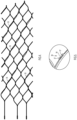
Classifications
-
- A—HUMAN NECESSITIES
- A61—MEDICAL OR VETERINARY SCIENCE; HYGIENE
- A61B—DIAGNOSIS; SURGERY; IDENTIFICATION
- A61B17/00—Surgical instruments, devices or methods
- A61B17/22—Implements for squeezing-off ulcers or the like on inner organs of the body; Implements for scraping-out cavities of body organs, e.g. bones; for invasive removal or destruction of calculus using mechanical vibrations; for removing obstructions in blood vessels, not otherwise provided for
- A61B17/221—Gripping devices in the form of loops or baskets for gripping calculi or similar types of obstructions
-
- A—HUMAN NECESSITIES
- A61—MEDICAL OR VETERINARY SCIENCE; HYGIENE
- A61B—DIAGNOSIS; SURGERY; IDENTIFICATION
- A61B17/00—Surgical instruments, devices or methods
- A61B17/22—Implements for squeezing-off ulcers or the like on inner organs of the body; Implements for scraping-out cavities of body organs, e.g. bones; for invasive removal or destruction of calculus using mechanical vibrations; for removing obstructions in blood vessels, not otherwise provided for
- A61B2017/22001—Angioplasty, e.g. PCTA
-
- A—HUMAN NECESSITIES
- A61—MEDICAL OR VETERINARY SCIENCE; HYGIENE
- A61B—DIAGNOSIS; SURGERY; IDENTIFICATION
- A61B17/00—Surgical instruments, devices or methods
- A61B17/22—Implements for squeezing-off ulcers or the like on inner organs of the body; Implements for scraping-out cavities of body organs, e.g. bones; for invasive removal or destruction of calculus using mechanical vibrations; for removing obstructions in blood vessels, not otherwise provided for
- A61B17/221—Gripping devices in the form of loops or baskets for gripping calculi or similar types of obstructions
- A61B2017/2212—Gripping devices in the form of loops or baskets for gripping calculi or similar types of obstructions having a closed distal end, e.g. a loop
-
- A—HUMAN NECESSITIES
- A61—MEDICAL OR VETERINARY SCIENCE; HYGIENE
- A61B—DIAGNOSIS; SURGERY; IDENTIFICATION
- A61B17/00—Surgical instruments, devices or methods
- A61B17/22—Implements for squeezing-off ulcers or the like on inner organs of the body; Implements for scraping-out cavities of body organs, e.g. bones; for invasive removal or destruction of calculus using mechanical vibrations; for removing obstructions in blood vessels, not otherwise provided for
- A61B17/221—Gripping devices in the form of loops or baskets for gripping calculi or similar types of obstructions
- A61B2017/2215—Gripping devices in the form of loops or baskets for gripping calculi or similar types of obstructions having an open distal end
-
- A—HUMAN NECESSITIES
- A61—MEDICAL OR VETERINARY SCIENCE; HYGIENE
- A61B—DIAGNOSIS; SURGERY; IDENTIFICATION
- A61B90/00—Instruments, implements or accessories specially adapted for surgery or diagnosis and not covered by any of the groups A61B1/00 - A61B50/00, e.g. for luxation treatment or for protecting wound edges
- A61B90/39—Markers, e.g. radio-opaque or breast lesions markers
- A61B2090/3966—Radiopaque markers visible in an X-ray image
Definitions
- each of the first, second, third and fourth struts has a proximal end portion, a distal end portion and a mid-portion with the mid-portion being located between the proximal and distal end portions, the first and second end portions being curved and the mid-portion being straight when the device is cut longitudinally and laid flat on a surface.
- the cylindrical body portion of the retrieval device 12 is coupled to the distal end of an elongate wire 16 via the use of one or more antennas 15 that extend proximally from the proximal end 14 of the cylindrical body.
- the retrieval device 20 includes three antennas 28a, 28b and 28c that are straight and arranged parallel to the longitudinal axis 22 of the cylindrical body 21 in the as-cut configuration as shown in FIG. 2A .
- tabs or loops 29a-c that may be located at the proximal-most end of the antennas 28a-c are removed.
- the antennas 28a-c are then connected to the distal end of an elongate member 16 like that disclosed above in conjunction with the description of FIG. 1 . That is, the proximal ends of the antennas 28a-c converge to a common area where they are attached to the distal end 18 of the elongate wire 16.
- adjacent cell structures share at least one of the first, second, third, fourth, fifth and sixth struts with one another with the adjacent cell structures being both longitudinally and circumferentially offset from one another.
- the cylindrical body 21 of retrieval device 20 has a length of about 30 millimeters and an expanded outer diameter of about 5 millimeters.
- the cell structures in the central body portion 25 of retrieval device 20 have a cell height H of between about 4.3 millimeters and about 4.6 millimeters, a cell length L1 of between about 4.6 millimeters and about 4.8 millimeters, a circumferential offset CO of between about 0.7 millimeters and about 0.8 millimeters, a longitudinal offset LO of between about 0.7 millimeters and about 0.9 millimeters, a strut width W of between about 0.07 millimeters and about 0.08 millimeters, with struts 5 and 6 having a length L2 of between about 0.9 millimeters to about 1.0 millimeters.
- a line extending between the straight antenna and across the proximal and distal ends of at least one of the fifth and sixth struts is straight and disposed parallel to the longitudinal axis of the cylindrical body of the retrieval device.
- each of antennas 28a and 28b is longitudinally aligned with at least one of the fifth and sixth struts of the cell structures residing in the central body portion 25 of the retrieval device 20.
- the retrieval device 20 is equipped with a radiopaque wire or ribbon 35 that meanders between the inside and outside of the cylindrical body 21 in a pattern that preferably extends along a substantial portion of the length of the cylindrical body as shown in FIG. 4 .
- at least some of the struts of the retrieval device comprise a retaining feature 36, as shown in FIG. 5 , through which the radiopaque wire or ribbon 35 passes as it meanders through the cylindrical body 21 of the retrieval device 20.
Landscapes
- Health & Medical Sciences (AREA)
- Surgery (AREA)
- Life Sciences & Earth Sciences (AREA)
- Heart & Thoracic Surgery (AREA)
- Molecular Biology (AREA)
- Vascular Medicine (AREA)
- Engineering & Computer Science (AREA)
- Biomedical Technology (AREA)
- Orthopedic Medicine & Surgery (AREA)
- Medical Informatics (AREA)
- Nuclear Medicine, Radiotherapy & Molecular Imaging (AREA)
- Animal Behavior & Ethology (AREA)
- General Health & Medical Sciences (AREA)
- Public Health (AREA)
- Veterinary Medicine (AREA)
- Prostheses (AREA)
- Surgical Instruments (AREA)
Description
- This application relates to and claims the benefit and priority to
U.S. Application No. 15/887,173, filed February 2, 2018 - The present disclosure relates to devices for retrieving obstructions from bodily ducts.
- An obstruction in a bodily duct of a patient can lead to chronic health issues, and even death, if the obstruction is left in place.
- An example of such an obstruction is an embolus located in a blood vessel of a patient. The embolus may be a blood clot (thrombus), a fat globule (fat embolism) or foreign material. An embolism can cause partial or total blockage of blood flow in the affected vessel, such as a vessel in the neurovasculature of a patient. The capture and removal of such blockages can prevent the occurrence of a stroke or at least partially reverse the effects of a stroke.
- A urinary tract obstruction is another example in which a blockage inhibits the flow of urine through its normal path (the urinary tract), including the kidneys, ureters, bladder, and urethra. Blockage can be complete or partial and can lead to kidney damage, kidney stones, and infection if not removed.
-
US 8,357,179B2 ;JP 6,231175B2 US 2015/080937 A1 , are examples of relevant known prior art in this field. - Disclosed herein are devices for capturing and removing obstructions from bodily ducts of a patient. The scope of the invention is defined by the appended claims.
- According to some implementations a device for retrieving an obstruction in a bodily duct of a patient is provided that comprises a cylindrical body having a circumference and a longitudinal axis and including a plurality of cell structures of substantially the same size and shape arranged in diagonal rows around the longitudinal axis. According to some implementations the plurality of cell structures each includes first, second, third, fourth, fifth and sixth struts, each of the first, second, third, fourth, fifth and sixth struts having a proximal end and a distal end. According to some implementations the proximal end of the first strut is coupled to the proximal end of the second strut, the distal end of the third strut is coupled to the distal end of the fourth strut, the distal end of the first strut is coupled to the proximal end of the fifth strut, the proximal end of the third strut is coupled to the distal end of the fifth strut, the distal end of the second strut is coupled to the proximal end of the sixth strut, the proximal end of the fourth strut is coupled to the distal end of the sixth strut. According to some implementations the proximal and distal ends of the fifth strut are longitudinally aligned with one another and reside at a first circumferential location and the proximal and distal ends of the sixth strut are longitudinally aligned with one another and reside at a second circumferential location, the second circumferential location being spaced apart from the first circumferential location. According to some implementations, when the retrieval device is cut longitudinally and laid flat on a surface at least a first portion of each of the first, second, third and fourth struts is curved and at least a second portion of each of the first, second, third and fourth struts is straight.
- According to other implementations, each of the first, second, third and fourth struts has a proximal end portion, a distal end portion and a mid-portion with the mid-portion being located between the proximal and distal end portions, the first and second end portions being curved and the mid-portion being straight when the device is cut longitudinally and laid flat on a surface.
- According to other implementations a device for capturing and removing an obstruction in a bodily duct of a patient is provided that comprises a cylindrical body having a circumference and a longitudinal axis and including a plurality of closed cell structures arranged in a plurality of diagonal rows disposed around the longitudinal axis. At least some of the plurality of closed cell structures being substantially the same shape and size, at least some of the closed cells structures of substantially the same shape and size occupying a same circumferential location in the cylindrical body and being longitudinally separated from one another by no less than two, three, four or more diagonal rows of closed cell structures.
- These and other advantages and features will become evident in view of the drawings and the detailed description.
-
-
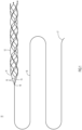
FIG. 1 shows a perspective view of an obstruction retrieval system according to some implementations; -
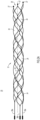
FIG. 2A is a perspective view of an obstruction retrieval device according to some implementations; -
FIG. 2B is a view of the obstruction retrieval device ofFIG. 2A as if the device were cut along a line parallel to its longitudinal axis and laid flat on a surface; -
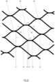
FIGS. 2C and2D each are an enlarged view of a portion of the cell structures depicted inFIG. 2B ; -
FIG. 2E illustrates dimensional characteristics of cell structures of an obstruction retrieval device according to some implementations; -
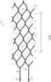
FIG. 3A is a perspective view of an obstruction retrieval device according to another implementation; -
FIG. 3B is a view of the obstruction retrieval device ofFIG. 3A as if the device were cut along a line parallel to its longitudinal axis and laid flat on a surface; -
FIG. 4 illustrates the obstruction retrieval device ofFIG. 2B with a radiopaque element dispersed therein; -
FIG. 5 is a perspective view of a strut of an obstruction retrieval device having a feature for receiving therein a portion of a radiopaque element. -
FIG. 1 shows a perspective view of anobstruction retrieval system 10 according to one implementation. The retrieval system includes a self-expandingretrieval device 12 comprising a cylindrical body, such as those depicted inFIGS. 2A and3A , having a proximal end 14 that is coupled to thedistal end 18 of anelongate wire 16 via a plurality ofantennas 15. Each of the plurality ofantennas 15 is connected at a proximal end to thedistal end 18 of theelongate wire 16, and connected at a distal end to the proximal end 14 of the cylindrical body. As discussed below in more detail, according to some implementations the proximal end of the cylindrical body is coupled to the distal end of the elongate wire by a single antenna that extends proximally from a side of the cylindrical body. - In the example of retrieving an embolus from a blood vessel in the neurovasculature of a patient, according to some implementations, in use the self-expanding retrieval device is loaded into a distal end portion of a delivery catheter (not shown) and delivered with the delivery catheter to the site of the embolus. According to some implementations the distal end portion of the delivery catheter is positioned across the embolus and then withdrawn proximally to deploy the retrieval device into the embolus. According to other implementations the distal end portion of the delivery catheter that carries the retrieval device is positioned distal to the embolus and then proximally withdrawn to deploy the retrieval device at a location distal to the embolus. In such a case the embolus is captured by retracting the
retrieval device 12 proximally into the embolus. This is accomplished by a clinician pulling on aproximal end portion 17 of the elongate wire 14 that resides outside the patient. - Keeping with the neurovascular obstruction example, upon the embolus being at least partially captured inside the
retrieval device 12, the retrieval device and the delivery catheter are singularly or together proximally withdrawn to effectuate a removal of the obstruction from the patient. According to some implementations theretrieval device 12 is at least partially withdrawn into the lumen of the delivery catheter during the removal process. - According to some implementations the
retrieval device 12 has a length of between about 10 millimeters to about 100 millimeters and the elongate wire 14 has a length of between about 150 centimeters to about 250 centimeters. - As will be discussed in more detail below, the anatomy of certain bodily ducts is tortuous having regions of tight bends. A problem with many existing retrieval devices is that the captured obstruction tends to disengage with the retrieval device as the retrieval device is maneuvered through this tortuous path. The retrieval devices disclosed herein comprise features that enhance their ability to capture an obstruction and to more effectively remove the obstruction from the patient through a tortuous path comprising tight bends.
-
FIGS. 2A and3A illustrate exemplaryretrieval devices FIGS. 2B and3B respectively show theretrieval devices retrieval devices cylindrical body longitudinal axis cylindrical bodies closed cell structures FIGS. 2A and3A represent the retrieval devices in an as-cut configuration typically resulting from the laser cutting of a metallic cylindrical tube made of, for example, a nickel-titanium alloy. It is important to note, however, that other manufacturing methods may be used to construct the retrieval devices disclosed herein. - In the example of
FIGS. 2A and2B , theretrieval device 20 includes twelve diagonal rows of cell structures R1-R12 and possesses acentral body portion 25 that extends between rows R3 and R11. According to some implementation, the cell structures that form thecentral body portion 25 are of substantially the same size and shape. According to some implementations, each row of cell structures in thecentral body portion 25 includes four cell structures that together surround thelongitudinal axis 22 of thecylindrical body 21. - In the example of
FIGS. 3A and3B , theretrieval device 60 includes eight diagonal rows of cell structures R1-R8 and possesses acentral body portion 65 that extends between rows R2 and R7. According to some implementation, the cell structures that form thecentral body portion 65 are of substantially the same size and shape. According to some implementations, each row of cell structures in thecentral body portion 65 includes three cell structures that together surround thelongitudinal axis 62 of thecylindrical body 61. - Retrieval devices having less than eight rows of cell structures, more than twelve rows of cell structures, and greater than four cell structures in a given row are also contemplated.
- As explained above in the discussion of
FIG. 1 , the cylindrical body portion of theretrieval device 12 is coupled to the distal end of anelongate wire 16 via the use of one ormore antennas 15 that extend proximally from the proximal end 14 of the cylindrical body. - In the implementation of
FIGS. 2A and2B theretrieval device 20 includes threeantennas longitudinal axis 22 of thecylindrical body 21 in the as-cut configuration as shown inFIG. 2A . After theretriever 20 has been formed and polished, tabs orloops 29a-c that may be located at the proximal-most end of theantennas 28a-c are removed. Theantennas 28a-c are then connected to the distal end of anelongate member 16 like that disclosed above in conjunction with the description ofFIG. 1 . That is, the proximal ends of theantennas 28a-c converge to a common area where they are attached to thedistal end 18 of theelongate wire 16. By virtue of their convergence, theantennas 28a-c cause theretrieval device 20 to have a partially closed proximal end. According to other implementations theretrieval device 20 comprises a single antenna. For example, according some implementations theretrieval device 20 includes a single antenna that extends from a side of thecylindrical body 61 so that the proximal end of the retrieval device is fully open. - In the implementation of
FIGS. 3A and3B theretrieval device 60 includes twoantennas longitudinal axis 62 of thecylindrical body 61 in the as-cut configuration. After theretriever 60 has been cut and polished, the proximal ends of theantennas 68a-b, which may comprisetabs 69a-b, are connected to the distal end of anelongate member 16 like that disclosed above in conjunction with the description ofFIG. 1 . That is, the proximal ends of theantennas 68a-b converge to a common area where they are attached to thedistal end 18 of theelongate wire 16. By virtue of their convergence, theantennas 28a-b cause theretrieval device 20 to have a partially closed proximal end. According to other implementations theretrieval device 60 comprises fewer or more than three antennas. For example, according some implementations theretrieval device 60 includes a single antenna that extends from a side of the cylindrical body so that the proximal end of the retrieval device is fully open. - In the implementations of
FIGS. 2A and3A , the distal end of theretrieval devices distal end distal-most end segments FIGS. 2A and3A , according to some implementations thedistal-most end segments - According to some implementations, the
cylindrical body 21 ofretrieval device 20 has a length of about 30 millimeters and an expanded outer diameter of about 5 millimeters. According to some implementations, the cylindrical body ofretrieval device 60 has a length of about 20 millimeters and an expanded outer diameter of about 3 millimeters. - In terms of capturing an obstruction (e.g. an embolus) in a stent-like retrieval device like those disclosed herein, the effectiveness of capturing the obstruction is compromised in the current state of the art retrieval devices as a result of the frequency by which the longitudinal and circumferential location of like (e.g. same size and shape) cell structures are repeated. To address this problem, according to some implementations, like cell structures in
retrieval devices FIGS. 2B and3B , like cell structures occupying a same circumferential location are separated by no less than four diagonal rows. An advantage of these configurations is that a greater degree of irregularity exits in the structure of the retrieval device along its length that enhances its ability to entrap an obstruction. This is a result of the obstruction being exposed to a greater number of different geometries along the length of the retrieval device which reduces slippage and improves integration of the obstruction into the retrieval device. - With reference to
FIG. 2B , like cell structures A1 and A2 occupy a same circumferential location in thecentral body portion 25 of thecylindrical body 21 with cell structure A1 residing in diagonal row R4 and cell structure A2 residing in diagonal row R9 with there being four intervening rows R5-R8 separating cell structures A1 and A2. Likewise, like cell structures B1 and B2 occupy a same circumferential location in thecentral body portion 25 of thecylindrical body 21 with cell structure B1 residing in diagonal row R6 and cell structure B2 residing in diagonal row R11 with there being four intervening rows R7-R10 separating cell structures B1 and B2. In addition, like cell structures C1 and C2 occupy a same circumferential location in thecentral body portion 25 of thecylindrical body 21 with cell structure C1 residing in diagonal row R3 and cell structure C2 residing in diagonal row R8 with there being four intervening rows R4-R7 separating cell structures C1 and C2. According to other implementations, like cell structures occupying a same circumferential location are separated by no less than three intervening diagonal rows of cell structures. - With reference to
FIG. 3B , like cell structures A1 and A2 occupy a same circumferential location in thecentral body portion 65 of thecylindrical body 61 with cell structure A1 residing in diagonal row R2 and cell structure A2 residing in diagonal row R7 with there being four intervening rows R3-R6 separating cell structures A1 and A2. Likewise, like cell structures B1 and B2 occupy a same circumferential location in thecentral body portion 65 of thecylindrical body 61 with cell structure B1 residing in diagonal row R3 and cell structure B2 residing in diagonal row R8 with there being four intervening rows R4-R7 separating cell structures B1 and B2. According to other implementations, like cell structures occupying a same circumferential location are separated by no less than three intervening diagonal rows of cell structures. -
FIG. 2C is an enlarged view of rows R3-R5 located in thecentral body portion 25 ofretrieval device 20 with cell structure A1 residing in row R4. The configuration of cell structure A1 is representative of at least a majority of the cell structures within theretrieval device 20. Cell structure A1 includes afirst strut 1, asecond strut 2, athird strut 3, afourth strut 4, afifth strut 5 and asixth strut 6, with each of the first, second, third, fourth, fifth and sixth struts having a proximal end and a distal end. The proximal end of thefirst strut 1 is coupled to the proximal end of thesecond strut 2 at a first longitudinal location L1, the distal end of thethird strut 3 is coupled to the distal end of thefourth strut 4 at a second longitudinal location L2 distal to the first longitudinal location L1, the distal end of thefirst strut 1 is coupled to the proximal end of thefifth strut 5 at a third longitudinal location L3 that is located between the first and second longitudinal locations L1 and L2, the proximal end of thethird strut 3 is coupled to the distal end of thefifth strut 5 at a fourth longitudinal location L4 located between the second and third longitudinal locations L2 and L3, the distal end of thesecond strut 2 is coupled to the proximal end of thesixth strut 6 at a fifth longitudinal location L5 that is located between the second and third longitudinal locations L2 and L3, the proximal end of thefourth strut 4 is coupled to the distal end of thesixth strut 6 at a sixth longitudinal location L6 that is located between the second and fifth longitudinal locations L2 and L5. - As best seen in
FIGS. 2B and3B , among the plurality of cell structures inretrieval devices - In the implementation of
FIG. 2C , when thecylindrical body 21 of theretrieval device 20 is cut longitudinally and laid flat on a surface the third and fourth longitudinal locations L3 and L4 are longitudinally aligned with one another (that is, a straight line drawn between longitudinal locations L3 and L4 is parallel to thelongitudinal axis 22 of the cylindrical body 21) and reside at a common first circumferential location, and the fifth and sixth longitudinal locations L5 and L6 are longitudinally aligned with one another (that is, a straight line drawn between longitudinal locations L5 and L6 is parallel to thelongitudinal axis 22 of the cylindrical body 21) and reside at a common second circumferential location with the second circumferential location being spaced apart from the first circumferential location. - According to some implementations, when the
cylindrical body 21 of theretrieval device 20 is cut longitudinally and laid flat on a surface at least one of thefifth strut 5 andsixth strut 6 is straight. According to other implementations each of thefifth strut 5 andsixth strut 6 is straight as shown inFIG. 2C . An advantage of one or both of the fifth and sixth struts being straight is that it advantageously endows theretriever 20 with a greater stiffness along its length than would otherwise exist if the struts were curved. - According to some implementations the fourth longitudinal location L4 and fifth longitudinal location L5 are circumferentially non-aligned with one another as shown in
FIG. 2C . According to other implementations the fourth longitudinal location L4 and fifth longitudinal location L5 are circumferentially aligned with one another. A circumferentially alignment of the fourth and fifth longitudinal locations circumferentially aligns the distal end of thefifth strut 5 with the proximal end of thesixth strut 6 to produce a longitudinally continuous straight section within the cell structure A1, albeit circumferentially offset, that assists in providing the retriever with zones of enhanced stiffness. - As discussed above, a problem associated with removing a captured obstruction from a patient through a tortuous pathway is that when the retrieval device carrying the obstruction encounters and conforms to a tight bend, the obstruction is prone to being at least partially dislodged from the retriever. An advantage of providing a retriever with enhanced longitudinal stiffness is that it allows the retriever to at least partially straighten the bends through which it passes during the obstruction removal process. This reduces the risk of the obstruction being dislodge from the retrieval device as it is carried across the bends.
- Another advantage of providing zones of enhanced longitudinal stiffness within the retrieval device is that it reduces the risk of the retrieval device buckling in procedures requiring the retrieval device to be pushed through the delivery catheter and/or through the bodily duct of the patient.
- According to some implementations when the device is cut longitudinally and laid flat on a surface, as depicted in
FIG. 2D , one or more or all of thefirst strut 1,second strut 2,third strut 3 andfourth strut 4 has a curved proximal end portion, a curved distal end portion and a straight portion located between the curved proximal and distal end portions. According to some implementations the straight portion is located in a middle portion of the strut. The curved proximal anddistal end portions retrieval device 20 with a requisite amount of flexibility to enable it to navigate through the anatomy of a patient. Thestraight portion 1c, 2c, 3c, 4c of struts 1-4 enhances the longitudinal stiffness of theretrieval device 20 to provide the retrieval device with an ability to at least partially straighten the bends through which it passes during an obstruction removal process. As explained above, this reduces the risk of the obstruction being dislodged from the retrieval device as it is carried across tight bends. Another advantage of the mid-portion being straight is that it reduces the risk of the retrieval device buckling (as compared to entirely curved struts) in procedures requiring the retrieval device to be pushed through the delivery catheter and/or through the bodily duct of the patient. - According to some implementations one or more or all of struts 1-4 includes one or more straight portion that cumulatively occupy 20% to 80% of the overall length of the respective strut. According to other implementations one or more or all of struts 1-4 includes one or more straight portions that cumulatively occupy 30% to 70% of the overall length of the respective strut. According to some implementations one or more or all of struts 1-4 includes a single continuous straight portion that occupies 20% to 80% of the overall length of the respective strut. According to other implementations one or more or all of struts 1-4 includes a single continuous straight portion that occupies 30% to 70% of the overall length of the respective strut.
- As noted above, according to some implementations the
cylindrical body 21 ofretrieval device 20 has a length of about 30 millimeters and an expanded outer diameter of about 5 millimeters. With reference toFIG. 2E , according to some implementations the cell structures in thecentral body portion 25 ofretrieval device 20 have a cell height H of between about 4.3 millimeters and about 4.6 millimeters, a cell length L1 of between about 4.6 millimeters and about 4.8 millimeters, a circumferential offset CO of between about 0.7 millimeters and about 0.8 millimeters, a longitudinal offset LO of between about 0.7 millimeters and about 0.9 millimeters, a strut width W of between about 0.07 millimeters and about 0.08 millimeters, withstruts - According to some implementations the
cylindrical body 61 ofretrieval device 60 has a length of about 20 millimeters and an expanded outer diameter of about 3 millimeters. With reference toFIG. 2E , according to some implementations the cell structures in thecentral body portion 65 ofretrieval device 60 have a cell height H of between about 3.7 millimeters and about 3.95 millimeters, a cell length L1 of between about 4.9 millimeters and about 5.5 millimeters, a circumferential offset CO of between about 0.7 millimeters and about 0.8 millimeters, a longitudinal offset LO of between about 1.15 millimeters and about 1.25 millimeters, a strut width W of between about 0.07 millimeters and about 0.08 millimeters, withstruts - As discussed above,
retrieval devices elongate wire 16 by one or more antennas that extend proximally from a proximal end of thecylindrical bodies retrieval devices FIGS. 2A ,2B ,3A and3B with at least one of the antennas being longitudinally aligned with the proximal and distal ends of at least one of thefifth struts 5 and/or with the proximal and distal ends of at least one of thesixth struts 6. That is, a line extending between the straight antenna and across the proximal and distal ends of at least one of the fifth and sixth struts is straight and disposed parallel to the longitudinal axis of the cylindrical body of the retrieval device. For example, as shown inFIG. 2B , each ofantennas central body portion 25 of theretrieval device 20. An advantage of such a configuration is that it reduces the risk of the retrieval device buckling when being pushed by theelongate wire 16. - It is sometimes important for the treating clinician to visualize the retrieval device during an obstruction remove procedure to ensure that the device is properly placed before being deployed. For this reason, according to some implementations the
retrieval device 20 is equipped with a radiopaque wire orribbon 35 that meanders between the inside and outside of thecylindrical body 21 in a pattern that preferably extends along a substantial portion of the length of the cylindrical body as shown inFIG. 4 . According to some implementations at least some of the struts of the retrieval device comprise a retainingfeature 36, as shown inFIG. 5 , through which the radiopaque wire orribbon 35 passes as it meanders through thecylindrical body 21 of theretrieval device 20. According to some implementations the retaining features 36 are formed during a laser cutting operation employed to construct the struts of the retrieval device. As discussed above, according to some implementations the retrieval device is constructed by laser cutting a cylindrical metallic tube to form the struts of the device. In the implementation ofFIG. 5 the retainingfeature 36 includes two L-shape likemembers 37 that are separated by agap 38 through which the radiopaque wire orribbon 35 passes when it assembled on the strut. - According to some implementations, the radiopaque wire or
ribbon 35 is assembled on the retrieval device when the retrieval device is in a fully expanded state, and as such, does not impact the outward radial force of the retrieval device during its use. Further, according to other implementations, the radiopaque wire orribbon 35 is assembled on the retrieval device in a manner such that it does not affect the flexure stiffness of the retrieval device. - While the foregoing disclosure contains many specifics, these should not be construed as limitations on the scope of what is claimed or of what may be claimed, but rather as descriptions of features specific to particular exemplary implementations. Certain features that are described in this specification in the context of separate implementations can also be implemented in combination in a single implementation. Conversely, various features that are described in the context of a single implementation can also be implemented in multiple implementations separately or in any suitable sub-combination. Moreover, although features may be described above as acting in certain combinations and even initially claimed as such, one or more features from a claimed combination can in some cases be excised from the combination, and the claimed combination may be directed to a sub-combination or a variation of a sub-combination. Variations, modifications and enhancements to the described examples and implementations and other implementations may be made based on what is disclosed. The scope of the subject-matter of the invention is thus defined only by the scope of the wording of the appended claims.
Claims (13)
- A device for capturing an obstruction in a bodily duct of a patient, the device comprising:a cylindrical body (21, 61) having a circumference and a longitudinal axis (22, 62) and including a plurality of cell structures of the same size and shape and arranged in diagonal rows (R1-R12) around the longitudinal axis, each of the plurality of cell structures including first, second, third, fourth and fifth cell structures, the first cell structure being surrounded by the second, third, fourth and fifth cell structures and sharing at least one strut with each of the second, third, fourth and fifth cell structures, the plurality of cell structures each includes first, second, third, fourth, fifth and sixth struts, each of the first, second, third, fourth, fifth and sixth struts (1-6) having a proximal end and a distal end,the proximal end of the first strut (1) being coupled to the proximal end of the second strut (2) at a first longitudinal location (L1), the distal end of the third strut (3) being coupled to the distal end of the fourth strut (4) at a second longitudinal location (L2) distal to the first longitudinal location (L1), the distal end of the first strut (1) being coupled to the proximal end of the fifth strut (5) at a third longitudinal location (L3), the proximal end of the third strut (3) being coupled to the distal end of the fifth strut (5) at a fourth longitudinal location (L4), the distal end of the second strut (2) being coupled to the proximal end of the sixth strut (6) at a fifth longitudinal location (L5), the proximal end of the fourth strut (4) being coupled to the distal end of the sixth strut at a sixth longitudinal location (L6), characterized in thatthe fourth longitudinal location (L4) being proximal to the sixth longitudinal location (L6), the proximal and distal ends of the fifth strut (5) being longitudinally aligned with one another and residing at a first circumferential location, the proximal and distal ends of the sixth strut (6) being longitudinally aligned with one another and residing at a second circumferential location, the second circumferential location being spaced apart from the first circumferential location, when the device is cut longitudinally and laid flat on a surface at least a first portion of each of the first, second, third and fourth struts is curved and at least a second portion of each of the first, second, third and fourth struts is straight.
- The device according to claim 1, wherein each of the first, second, third and fourth struts (1-4) has a proximal end portion (1a, 2a, 3a, 4a), a distal end portion (1b, 2b, 3b, 4b) and a mid-portion (1c, 2c, 3c, 4c), the mid-portion being located between the proximal and distal end portions, the proximal and distal end portions being curved and the mid-portion being straight when the device is cut longitudinally and laid flat on a surface.
- The device according to any of claims 1 - 2, wherein when the device is cut longitudinally and laid flat on a surface at least one of the fifth and sixth struts (5, 6) is straight.
- The device according to any of claims 1 - 2, wherein when the device is cut longitudinally and laid flat on a surface each of the fifth and sixth struts (5, 6) is straight.
- The device according to claim 1, wherein the cylindrical body (21, 61) has a proximal end (14) and a distal end (26, 56) and a first of the plurality of cell structures (A1, B1, C1) is longitudinally aligned with a second of the plurality of cell structures (A2, B2, C2), the first of the plurality of cell structures (A1, B1, C1) being located in the cylindrical body proximally to the second of the plurality of cell structures, each of the first and second plurality of cell structures having a proximal end and a distal end, an imaginary longitudinal straight line running parallel to the longitudinal axis (22, 62) and joining the distal end of the first of the plurality of cell structures with the proximal end of the second of the plurality of cell structures intersects at least two intervening cell structures, the second of the plurality of cell structures (A2, B2, C2) being located nearer the first of the plurality of cell structures (A1, B1, C1) than any of another of the plurality of cell structures that are longitudinally aligned with the first of the plurality of cell structures.
- The device according to claim 1, wherein a first of the plurality of cell structures (A1, B1, C1) is longitudinally aligned with a second of the plurality of cell structures (A2, B2, C2), an imaginary longitudinal straight line running parallel to the longitudinal axis (22, 62) and joining the fifth struts (5) or the sixth struts (6) of the first and second cell structures intersects at least three intervening cell structures.
- The device according to claim 1, wherein a first of the plurality of cell structures (A1, B1, C1) is longitudinally aligned with a second of the plurality of cell structures (A2, B2, C2), an imaginary longitudinal straight line running parallel to the longitudinal axis (22, 62) and joining the fifth struts (5) or the sixth struts (6) of the first and second cell structures intersects at least four intervening cell structures.
- The device according to claim 1, wherein a first of the plurality of cell structures (A1, B1, C1) and a second of the plurality of cell structures (A2, B2, C2) occupy a same circumferential location and are longitudinally separated by no less than two diagonal rows (R1-R12).
- The device according to claim 1, wherein a first of the plurality of cell structures (A1, B1, C1) and a second of the plurality of cell structures (A2, B2, C2) occupy a same circumferential location and are longitudinally separated by no less than three diagonal rows (R1-R12)
- The device according to claim 1, wherein a first of the plurality of cell structures (A1, B1, C1) and a second of the plurality of cell structures (A2, B2, C2) occupy a same circumferential location and are longitudinally separated by no less than four diagonal rows (R1 - R12),
- The device according to claim 1, wherein the distal end of the fifth strut (5) and the proximal end of the sixth strut (6) are circumferentially aligned.
- The device according to claim 1, wherein the fourth longitudinal location (L4) and fifth longitudinal location (L5) are circumferentially aligned.
- The device according to claim 2, wherein the mid-portion of one or more or all of the first, second, third and fourth struts occupies 30% to 70% of an overall length of the respective strut.
Applications Claiming Priority (2)
| Application Number | Priority Date | Filing Date | Title |
|---|---|---|---|
| US15/887,173 US10179000B1 (en) | 2018-02-02 | 2018-02-02 | Devices for retrieving an obstruction in a bodily duct of a patient |
| PCT/US2019/012278 WO2019152132A1 (en) | 2018-02-02 | 2019-01-04 | Devices for retrieving an obstruction in a bodily duct of a patient |
Publications (3)
| Publication Number | Publication Date |
|---|---|
| EP3745968A1 EP3745968A1 (en) | 2020-12-09 |
| EP3745968A4 EP3745968A4 (en) | 2021-11-24 |
| EP3745968B1 true EP3745968B1 (en) | 2025-04-09 |
Family
ID=63685285
Family Applications (1)
| Application Number | Title | Priority Date | Filing Date |
|---|---|---|---|
| EP19747621.1A Active EP3745968B1 (en) | 2018-02-02 | 2019-01-04 | Devices for retrieving an obstruction in a bodily duct of a patient |
Country Status (5)
| Country | Link |
|---|---|
| US (7) | US10092309B1 (en) |
| EP (1) | EP3745968B1 (en) |
| JP (3) | JP7089600B2 (en) |
| CN (2) | CN111670015B (en) |
| WO (1) | WO2019152132A1 (en) |
Families Citing this family (3)
| Publication number | Priority date | Publication date | Assignee | Title |
|---|---|---|---|---|
| WO2018161959A1 (en) * | 2017-03-10 | 2018-09-13 | 上海心玮医疗科技有限公司 | Thrombectomy device system |
| US10092309B1 (en) | 2018-02-02 | 2018-10-09 | Highway 1 Medical, Inc. | Devices for retrieving an obstruction in a bodily duct of a patient |
| WO2023087455A1 (en) * | 2021-11-17 | 2023-05-25 | 上海腾复医疗科技有限公司 | Vascular recanalization device |
Family Cites Families (21)
| Publication number | Priority date | Publication date | Assignee | Title |
|---|---|---|---|---|
| US5102417A (en) | 1985-11-07 | 1992-04-07 | Expandable Grafts Partnership | Expandable intraluminal graft, and method and apparatus for implanting an expandable intraluminal graft |
| WO1996023446A1 (en) | 1995-02-02 | 1996-08-08 | Boston Scientific Corporation | Surgical wire basket extractor |
| US6402771B1 (en) | 1999-12-23 | 2002-06-11 | Guidant Endovascular Solutions | Snare |
| DE10233085B4 (en) | 2002-07-19 | 2014-02-20 | Dendron Gmbh | Stent with guide wire |
| US8882826B2 (en) * | 2006-08-22 | 2014-11-11 | Abbott Cardiovascular Systems Inc. | Intravascular stent |
| DE07841109T1 (en) | 2006-08-22 | 2010-02-11 | Abbott Cardiovascular Systems Inc., Santa Clara | INTRAVASCULAR STENT |
| US8585713B2 (en) | 2007-10-17 | 2013-11-19 | Covidien Lp | Expandable tip assembly for thrombus management |
| US8088140B2 (en) | 2008-05-19 | 2012-01-03 | Mindframe, Inc. | Blood flow restorative and embolus removal methods |
| CN103549986B (en) * | 2008-02-22 | 2015-12-09 | 泰科保健集团有限合伙公司 | The thrombosis device agglomerate of removable combination |
| US8357179B2 (en) * | 2009-07-08 | 2013-01-22 | Concentric Medical, Inc. | Vascular and bodily duct treatment devices and methods |
| US8795317B2 (en) * | 2009-07-08 | 2014-08-05 | Concentric Medical, Inc. | Embolic obstruction retrieval devices and methods |
| US20110009941A1 (en) * | 2009-07-08 | 2011-01-13 | Concentric Medical, Inc. | Vascular and bodily duct treatment devices and methods |
| US20120123466A1 (en) * | 2010-11-12 | 2012-05-17 | Stryker Nv Operations, Ltd. | Axially variable radial pressure cages for clot capture |
| KR101680420B1 (en) * | 2011-02-04 | 2016-11-28 | 콘센트릭 메디칼, 인크. | Vascular and bodily duct treatment devices and methods |
| PL2967610T3 (en) * | 2013-03-14 | 2019-07-31 | Neuravi Limited | A clot retrieval device for removing occlusive clot from a blood vessel |
| US9393035B2 (en) * | 2013-04-12 | 2016-07-19 | Yongyi Alan Yu | Systems and methods for restoring blood flow to a vessel |
| US10076399B2 (en) * | 2013-09-13 | 2018-09-18 | Covidien Lp | Endovascular device engagement |
| AU2015211058A1 (en) | 2014-01-29 | 2016-08-11 | Concentric Medical, Inc. | Vascular and bodily duct treatment devices and methods |
| WO2017062383A1 (en) * | 2015-10-07 | 2017-04-13 | Stryker Corporation | Multiple barrel clot removal devices |
| US10342571B2 (en) * | 2015-10-23 | 2019-07-09 | Inari Medical, Inc. | Intravascular treatment of vascular occlusion and associated devices, systems, and methods |
| US10092309B1 (en) * | 2018-02-02 | 2018-10-09 | Highway 1 Medical, Inc. | Devices for retrieving an obstruction in a bodily duct of a patient |
-
2018
- 2018-02-02 US US15/887,261 patent/US10092309B1/en active Active
- 2018-02-02 US US15/887,173 patent/US10179000B1/en active Active
- 2018-09-06 US US16/123,517 patent/US10245054B1/en active Active
-
2019
- 2019-01-04 CN CN201980011312.3A patent/CN111670015B/en active Active
- 2019-01-04 CN CN202410478055.7A patent/CN118340555A/en active Pending
- 2019-01-04 EP EP19747621.1A patent/EP3745968B1/en active Active
- 2019-01-04 WO PCT/US2019/012278 patent/WO2019152132A1/en not_active Ceased
- 2019-01-04 JP JP2020563889A patent/JP7089600B2/en active Active
- 2019-02-14 US US16/275,806 patent/US11071558B2/en active Active
-
2021
- 2021-06-28 US US17/360,509 patent/US11883045B2/en active Active
-
2022
- 2022-04-28 JP JP2022074281A patent/JP7466586B2/en active Active
-
2023
- 2023-11-30 JP JP2023203303A patent/JP7691477B2/en active Active
- 2023-12-27 US US18/397,309 patent/US12349931B2/en active Active
-
2025
- 2025-07-07 US US19/261,400 patent/US20260123946A1/en active Pending
Also Published As
| Publication number | Publication date |
|---|---|
| US10092309B1 (en) | 2018-10-09 |
| US20210322039A1 (en) | 2021-10-21 |
| CN111670015B (en) | 2024-06-25 |
| US12349931B2 (en) | 2025-07-08 |
| US10179000B1 (en) | 2019-01-15 |
| WO2019152132A1 (en) | 2019-08-08 |
| US20190239906A1 (en) | 2019-08-08 |
| JP7089600B2 (en) | 2022-06-22 |
| US11883045B2 (en) | 2024-01-30 |
| JP2022106876A (en) | 2022-07-20 |
| JP2021512762A (en) | 2021-05-20 |
| CN118340555A (en) | 2024-07-16 |
| JP7691477B2 (en) | 2025-06-11 |
| EP3745968A1 (en) | 2020-12-09 |
| US20260123946A1 (en) | 2026-05-07 |
| US20240315715A1 (en) | 2024-09-26 |
| EP3745968A4 (en) | 2021-11-24 |
| JP2024023482A (en) | 2024-02-21 |
| CN111670015A (en) | 2020-09-15 |
| US11071558B2 (en) | 2021-07-27 |
| US10245054B1 (en) | 2019-04-02 |
| JP7466586B2 (en) | 2024-04-12 |
Similar Documents
| Publication | Publication Date | Title |
|---|---|---|
| US12349931B2 (en) | Devices for retrieving an obstruction in a bodily duct of a patient | |
| US8795345B2 (en) | Vascular and bodily duct treatment devices and methods | |
| US8529596B2 (en) | Vascular and bodily duct treatment devices and methods | |
| US20150209165A1 (en) | Vascular and bodily duct treatment devices and methods | |
| US8357179B2 (en) | Vascular and bodily duct treatment devices and methods | |
| US8795317B2 (en) | Embolic obstruction retrieval devices and methods | |
| US8357178B2 (en) | Vascular and bodily duct treatment devices and methods | |
| US9072537B2 (en) | Vascular and bodily duct treatment devices and methods | |
| AU2010271300C1 (en) | Vascular and bodily duct treatment devices and methods | |
| JP7263377B2 (en) | thrombectomy device | |
| US12446906B2 (en) | Clot retrieval device for ischemic stroke treatment |
Legal Events
| Date | Code | Title | Description |
|---|---|---|---|
| STAA | Information on the status of an ep patent application or granted ep patent |
Free format text: STATUS: THE INTERNATIONAL PUBLICATION HAS BEEN MADE |
|
| PUAI | Public reference made under article 153(3) epc to a published international application that has entered the european phase |
Free format text: ORIGINAL CODE: 0009012 |
|
| STAA | Information on the status of an ep patent application or granted ep patent |
Free format text: STATUS: REQUEST FOR EXAMINATION WAS MADE |
|
| 17P | Request for examination filed |
Effective date: 20200902 |
|
| AK | Designated contracting states |
Kind code of ref document: A1 Designated state(s): AL AT BE BG CH CY CZ DE DK EE ES FI FR GB GR HR HU IE IS IT LI LT LU LV MC MK MT NL NO PL PT RO RS SE SI SK SM TR |
|
| AX | Request for extension of the european patent |
Extension state: BA ME |
|
| DAV | Request for validation of the european patent (deleted) | ||
| DAX | Request for extension of the european patent (deleted) | ||
| A4 | Supplementary search report drawn up and despatched |
Effective date: 20211022 |
|
| RIC1 | Information provided on ipc code assigned before grant |
Ipc: A61F 2/844 20130101ALI20211018BHEP Ipc: A61F 2/82 20130101ALI20211018BHEP Ipc: A61F 2/04 20130101ALI20211018BHEP Ipc: A61F 2/01 20060101ALI20211018BHEP Ipc: A61B 17/3207 20060101ALI20211018BHEP Ipc: A61B 17/221 20060101AFI20211018BHEP |
|
| GRAP | Despatch of communication of intention to grant a patent |
Free format text: ORIGINAL CODE: EPIDOSNIGR1 |
|
| STAA | Information on the status of an ep patent application or granted ep patent |
Free format text: STATUS: GRANT OF PATENT IS INTENDED |
|
| INTG | Intention to grant announced |
Effective date: 20241118 |
|
| RIN1 | Information on inventor provided before grant (corrected) |
Inventor name: WILSON, SCOTT, D. Inventor name: SHINSKY, VERA |
|
| GRAS | Grant fee paid |
Free format text: ORIGINAL CODE: EPIDOSNIGR3 |
|
| GRAA | (expected) grant |
Free format text: ORIGINAL CODE: 0009210 |
|
| STAA | Information on the status of an ep patent application or granted ep patent |
Free format text: STATUS: THE PATENT HAS BEEN GRANTED |
|
| AK | Designated contracting states |
Kind code of ref document: B1 Designated state(s): AL AT BE BG CH CY CZ DE DK EE ES FI FR GB GR HR HU IE IS IT LI LT LU LV MC MK MT NL NO PL PT RO RS SE SI SK SM TR |
|
| REG | Reference to a national code |
Ref country code: GB Ref legal event code: FG4D |
|
| REG | Reference to a national code |
Ref country code: CH Ref legal event code: EP |
|
| REG | Reference to a national code |
Ref country code: DE Ref legal event code: R096 Ref document number: 602019068411 Country of ref document: DE |
|
| REG | Reference to a national code |
Ref country code: IE Ref legal event code: FG4D |
|
| REG | Reference to a national code |
Ref country code: NL Ref legal event code: MP Effective date: 20250409 |
|
| PG25 | Lapsed in a contracting state [announced via postgrant information from national office to epo] |
Ref country code: NL Free format text: LAPSE BECAUSE OF FAILURE TO SUBMIT A TRANSLATION OF THE DESCRIPTION OR TO PAY THE FEE WITHIN THE PRESCRIBED TIME-LIMIT Effective date: 20250409 |
|
| REG | Reference to a national code |
Ref country code: AT Ref legal event code: MK05 Ref document number: 1782813 Country of ref document: AT Kind code of ref document: T Effective date: 20250409 |
|
| PG25 | Lapsed in a contracting state [announced via postgrant information from national office to epo] |
Ref country code: PT Free format text: LAPSE BECAUSE OF FAILURE TO SUBMIT A TRANSLATION OF THE DESCRIPTION OR TO PAY THE FEE WITHIN THE PRESCRIBED TIME-LIMIT Effective date: 20250811 Ref country code: FI Free format text: LAPSE BECAUSE OF FAILURE TO SUBMIT A TRANSLATION OF THE DESCRIPTION OR TO PAY THE FEE WITHIN THE PRESCRIBED TIME-LIMIT Effective date: 20250409 Ref country code: ES Free format text: LAPSE BECAUSE OF FAILURE TO SUBMIT A TRANSLATION OF THE DESCRIPTION OR TO PAY THE FEE WITHIN THE PRESCRIBED TIME-LIMIT Effective date: 20250409 |
|
| REG | Reference to a national code |
Ref country code: LT Ref legal event code: MG9D |
|
| PG25 | Lapsed in a contracting state [announced via postgrant information from national office to epo] |
Ref country code: NO Free format text: LAPSE BECAUSE OF FAILURE TO SUBMIT A TRANSLATION OF THE DESCRIPTION OR TO PAY THE FEE WITHIN THE PRESCRIBED TIME-LIMIT Effective date: 20250709 Ref country code: GR Free format text: LAPSE BECAUSE OF FAILURE TO SUBMIT A TRANSLATION OF THE DESCRIPTION OR TO PAY THE FEE WITHIN THE PRESCRIBED TIME-LIMIT Effective date: 20250710 |
|
| PG25 | Lapsed in a contracting state [announced via postgrant information from national office to epo] |
Ref country code: PL Free format text: LAPSE BECAUSE OF FAILURE TO SUBMIT A TRANSLATION OF THE DESCRIPTION OR TO PAY THE FEE WITHIN THE PRESCRIBED TIME-LIMIT Effective date: 20250409 |
|
| PG25 | Lapsed in a contracting state [announced via postgrant information from national office to epo] |
Ref country code: BG Free format text: LAPSE BECAUSE OF FAILURE TO SUBMIT A TRANSLATION OF THE DESCRIPTION OR TO PAY THE FEE WITHIN THE PRESCRIBED TIME-LIMIT Effective date: 20250409 |
|
| PG25 | Lapsed in a contracting state [announced via postgrant information from national office to epo] |
Ref country code: HR Free format text: LAPSE BECAUSE OF FAILURE TO SUBMIT A TRANSLATION OF THE DESCRIPTION OR TO PAY THE FEE WITHIN THE PRESCRIBED TIME-LIMIT Effective date: 20250409 |
|
| PG25 | Lapsed in a contracting state [announced via postgrant information from national office to epo] |
Ref country code: AT Free format text: LAPSE BECAUSE OF FAILURE TO SUBMIT A TRANSLATION OF THE DESCRIPTION OR TO PAY THE FEE WITHIN THE PRESCRIBED TIME-LIMIT Effective date: 20250409 |
|
| PG25 | Lapsed in a contracting state [announced via postgrant information from national office to epo] |
Ref country code: RS Free format text: LAPSE BECAUSE OF FAILURE TO SUBMIT A TRANSLATION OF THE DESCRIPTION OR TO PAY THE FEE WITHIN THE PRESCRIBED TIME-LIMIT Effective date: 20250709 |
|
| PG25 | Lapsed in a contracting state [announced via postgrant information from national office to epo] |
Ref country code: IS Free format text: LAPSE BECAUSE OF FAILURE TO SUBMIT A TRANSLATION OF THE DESCRIPTION OR TO PAY THE FEE WITHIN THE PRESCRIBED TIME-LIMIT Effective date: 20250809 |
|
| PG25 | Lapsed in a contracting state [announced via postgrant information from national office to epo] |
Ref country code: LV Free format text: LAPSE BECAUSE OF FAILURE TO SUBMIT A TRANSLATION OF THE DESCRIPTION OR TO PAY THE FEE WITHIN THE PRESCRIBED TIME-LIMIT Effective date: 20250409 |
|
| PGFP | Annual fee paid to national office [announced via postgrant information from national office to epo] |
Ref country code: GB Payment date: 20251222 Year of fee payment: 8 |
|
| REG | Reference to a national code |
Ref country code: DE Ref legal event code: R097 Ref document number: 602019068411 Country of ref document: DE |
|
| PG25 | Lapsed in a contracting state [announced via postgrant information from national office to epo] |
Ref country code: DK Free format text: LAPSE BECAUSE OF FAILURE TO SUBMIT A TRANSLATION OF THE DESCRIPTION OR TO PAY THE FEE WITHIN THE PRESCRIBED TIME-LIMIT Effective date: 20250409 Ref country code: SM Free format text: LAPSE BECAUSE OF FAILURE TO SUBMIT A TRANSLATION OF THE DESCRIPTION OR TO PAY THE FEE WITHIN THE PRESCRIBED TIME-LIMIT Effective date: 20250409 |
|
| PGFP | Annual fee paid to national office [announced via postgrant information from national office to epo] |
Ref country code: FR Payment date: 20251222 Year of fee payment: 8 |
|
| PG25 | Lapsed in a contracting state [announced via postgrant information from national office to epo] |
Ref country code: CZ Free format text: LAPSE BECAUSE OF FAILURE TO SUBMIT A TRANSLATION OF THE DESCRIPTION OR TO PAY THE FEE WITHIN THE PRESCRIBED TIME-LIMIT Effective date: 20250409 |
|
| PG25 | Lapsed in a contracting state [announced via postgrant information from national office to epo] |
Ref country code: EE Free format text: LAPSE BECAUSE OF FAILURE TO SUBMIT A TRANSLATION OF THE DESCRIPTION OR TO PAY THE FEE WITHIN THE PRESCRIBED TIME-LIMIT Effective date: 20250409 |
|
| PG25 | Lapsed in a contracting state [announced via postgrant information from national office to epo] |
Ref country code: RO Free format text: LAPSE BECAUSE OF FAILURE TO SUBMIT A TRANSLATION OF THE DESCRIPTION OR TO PAY THE FEE WITHIN THE PRESCRIBED TIME-LIMIT Effective date: 20250409 Ref country code: SK Free format text: LAPSE BECAUSE OF FAILURE TO SUBMIT A TRANSLATION OF THE DESCRIPTION OR TO PAY THE FEE WITHIN THE PRESCRIBED TIME-LIMIT Effective date: 20250409 |
|
| PG25 | Lapsed in a contracting state [announced via postgrant information from national office to epo] |
Ref country code: IT Free format text: LAPSE BECAUSE OF FAILURE TO SUBMIT A TRANSLATION OF THE DESCRIPTION OR TO PAY THE FEE WITHIN THE PRESCRIBED TIME-LIMIT Effective date: 20250409 |
|
| PLBE | No opposition filed within time limit |
Free format text: ORIGINAL CODE: 0009261 |
|
| STAA | Information on the status of an ep patent application or granted ep patent |
Free format text: STATUS: NO OPPOSITION FILED WITHIN TIME LIMIT |
|
| REG | Reference to a national code |
Ref country code: CH Ref legal event code: L10 Free format text: ST27 STATUS EVENT CODE: U-0-0-L10-L00 (AS PROVIDED BY THE NATIONAL OFFICE) Effective date: 20260218 |
|
| 26N | No opposition filed |
Effective date: 20260112 |
|
| PGFP | Annual fee paid to national office [announced via postgrant information from national office to epo] |
Ref country code: DE Payment date: 20251230 Year of fee payment: 8 |