EP3745594A2 - Diagnostic element for validation of bolt detection of a guard locking switch in a static state - Google Patents
Diagnostic element for validation of bolt detection of a guard locking switch in a static state Download PDFInfo
- Publication number
- EP3745594A2 EP3745594A2 EP20177357.9A EP20177357A EP3745594A2 EP 3745594 A2 EP3745594 A2 EP 3745594A2 EP 20177357 A EP20177357 A EP 20177357A EP 3745594 A2 EP3745594 A2 EP 3745594A2
- Authority
- EP
- European Patent Office
- Prior art keywords
- diagnostic
- locking
- inductive
- switch
- capacitor
- Prior art date
- Legal status (The legal status is an assumption and is not a legal conclusion. Google has not performed a legal analysis and makes no representation as to the accuracy of the status listed.)
- Granted
Links
Images






Classifications
-
- H—ELECTRICITY
- H03—ELECTRONIC CIRCUITRY
- H03K—PULSE TECHNIQUE
- H03K17/00—Electronic switching or gating, i.e. not by contact-making and –breaking
- H03K17/94—Electronic switching or gating, i.e. not by contact-making and –breaking characterised by the way in which the control signals are generated
- H03K17/945—Proximity switches
- H03K17/95—Proximity switches using a magnetic detector
- H03K17/9512—Proximity switches using a magnetic detector using digital techniques
-
- G—PHYSICS
- G07—CHECKING-DEVICES
- G07C—TIME OR ATTENDANCE REGISTERS; REGISTERING OR INDICATING THE WORKING OF MACHINES; GENERATING RANDOM NUMBERS; VOTING OR LOTTERY APPARATUS; ARRANGEMENTS, SYSTEMS OR APPARATUS FOR CHECKING NOT PROVIDED FOR ELSEWHERE
- G07C9/00—Individual registration on entry or exit
- G07C9/20—Individual registration on entry or exit involving the use of a pass
- G07C9/28—Individual registration on entry or exit involving the use of a pass the pass enabling tracking or indicating presence
-
- G—PHYSICS
- G01—MEASURING; TESTING
- G01D—MEASURING NOT SPECIALLY ADAPTED FOR A SPECIFIC VARIABLE; ARRANGEMENTS FOR MEASURING TWO OR MORE VARIABLES NOT COVERED IN A SINGLE OTHER SUBCLASS; TARIFF METERING APPARATUS; MEASURING OR TESTING NOT OTHERWISE PROVIDED FOR
- G01D5/00—Mechanical means for transferring the output of a sensing member; Means for converting the output of a sensing member to another variable where the form or nature of the sensing member does not constrain the means for converting; Transducers not specially adapted for a specific variable
- G01D5/12—Mechanical means for transferring the output of a sensing member; Means for converting the output of a sensing member to another variable where the form or nature of the sensing member does not constrain the means for converting; Transducers not specially adapted for a specific variable using electric or magnetic means
- G01D5/243—Mechanical means for transferring the output of a sensing member; Means for converting the output of a sensing member to another variable where the form or nature of the sensing member does not constrain the means for converting; Transducers not specially adapted for a specific variable using electric or magnetic means influencing the phase or frequency of AC
-
- E—FIXED CONSTRUCTIONS
- E05—LOCKS; KEYS; WINDOW OR DOOR FITTINGS; SAFES
- E05B—LOCKS; ACCESSORIES THEREFOR; HANDCUFFS
- E05B15/00—Other details of locks; Parts for engagement by bolts of fastening devices
- E05B15/10—Bolts of locks or night latches
-
- E—FIXED CONSTRUCTIONS
- E05—LOCKS; KEYS; WINDOW OR DOOR FITTINGS; SAFES
- E05B—LOCKS; ACCESSORIES THEREFOR; HANDCUFFS
- E05B47/00—Operating or controlling locks or other fastening devices by electric or magnetic means
-
- F—MECHANICAL ENGINEERING; LIGHTING; HEATING; WEAPONS; BLASTING
- F16—ENGINEERING ELEMENTS AND UNITS; GENERAL MEASURES FOR PRODUCING AND MAINTAINING EFFECTIVE FUNCTIONING OF MACHINES OR INSTALLATIONS; THERMAL INSULATION IN GENERAL
- F16P—SAFETY DEVICES IN GENERAL; SAFETY DEVICES FOR PRESSES
- F16P3/00—Safety devices acting in conjunction with the control or operation of a machine; Control arrangements requiring the simultaneous use of two or more parts of the body
- F16P3/08—Safety devices acting in conjunction with the control or operation of a machine; Control arrangements requiring the simultaneous use of two or more parts of the body in connection with the locking of doors, covers, guards, or like members giving access to moving machine parts
-
- F—MECHANICAL ENGINEERING; LIGHTING; HEATING; WEAPONS; BLASTING
- F16—ENGINEERING ELEMENTS AND UNITS; GENERAL MEASURES FOR PRODUCING AND MAINTAINING EFFECTIVE FUNCTIONING OF MACHINES OR INSTALLATIONS; THERMAL INSULATION IN GENERAL
- F16P—SAFETY DEVICES IN GENERAL; SAFETY DEVICES FOR PRESSES
- F16P3/00—Safety devices acting in conjunction with the control or operation of a machine; Control arrangements requiring the simultaneous use of two or more parts of the body
- F16P3/12—Safety devices acting in conjunction with the control or operation of a machine; Control arrangements requiring the simultaneous use of two or more parts of the body with means, e.g. feelers, which in case of the presence of a body part of a person in or near the danger zone influence the control or operation of the machine
- F16P3/14—Safety devices acting in conjunction with the control or operation of a machine; Control arrangements requiring the simultaneous use of two or more parts of the body with means, e.g. feelers, which in case of the presence of a body part of a person in or near the danger zone influence the control or operation of the machine the means being photocells or other devices sensitive without mechanical contact
- F16P3/147—Safety devices acting in conjunction with the control or operation of a machine; Control arrangements requiring the simultaneous use of two or more parts of the body with means, e.g. feelers, which in case of the presence of a body part of a person in or near the danger zone influence the control or operation of the machine the means being photocells or other devices sensitive without mechanical contact using electro-magnetic technology, e.g. tags or radar
-
- G—PHYSICS
- G07—CHECKING-DEVICES
- G07C—TIME OR ATTENDANCE REGISTERS; REGISTERING OR INDICATING THE WORKING OF MACHINES; GENERATING RANDOM NUMBERS; VOTING OR LOTTERY APPARATUS; ARRANGEMENTS, SYSTEMS OR APPARATUS FOR CHECKING NOT PROVIDED FOR ELSEWHERE
- G07C9/00—Individual registration on entry or exit
- G07C9/00174—Electronically operated locks; Circuits therefor; Nonmechanical keys therefor, e.g. passive or active electrical keys or other data carriers without mechanical keys
- G07C9/00658—Electronically operated locks; Circuits therefor; Nonmechanical keys therefor, e.g. passive or active electrical keys or other data carriers without mechanical keys operated by passive electrical keys
- G07C9/00714—Electronically operated locks; Circuits therefor; Nonmechanical keys therefor, e.g. passive or active electrical keys or other data carriers without mechanical keys operated by passive electrical keys with passive electrical components, e.g. resistor, capacitor, inductor
-
- G—PHYSICS
- G07—CHECKING-DEVICES
- G07C—TIME OR ATTENDANCE REGISTERS; REGISTERING OR INDICATING THE WORKING OF MACHINES; GENERATING RANDOM NUMBERS; VOTING OR LOTTERY APPARATUS; ARRANGEMENTS, SYSTEMS OR APPARATUS FOR CHECKING NOT PROVIDED FOR ELSEWHERE
- G07C9/00—Individual registration on entry or exit
- G07C9/00174—Electronically operated locks; Circuits therefor; Nonmechanical keys therefor, e.g. passive or active electrical keys or other data carriers without mechanical keys
- G07C9/00658—Electronically operated locks; Circuits therefor; Nonmechanical keys therefor, e.g. passive or active electrical keys or other data carriers without mechanical keys operated by passive electrical keys
- G07C9/00722—Electronically operated locks; Circuits therefor; Nonmechanical keys therefor, e.g. passive or active electrical keys or other data carriers without mechanical keys operated by passive electrical keys with magnetic components, e.g. magnets, magnetic strips, metallic inserts
-
- H—ELECTRICITY
- H03—ELECTRONIC CIRCUITRY
- H03K—PULSE TECHNIQUE
- H03K17/00—Electronic switching or gating, i.e. not by contact-making and –breaking
- H03K17/94—Electronic switching or gating, i.e. not by contact-making and –breaking characterised by the way in which the control signals are generated
- H03K17/945—Proximity switches
- H03K17/95—Proximity switches using a magnetic detector
- H03K17/9502—Measures for increasing reliability
-
- H—ELECTRICITY
- H03—ELECTRONIC CIRCUITRY
- H03K—PULSE TECHNIQUE
- H03K17/00—Electronic switching or gating, i.e. not by contact-making and –breaking
- H03K17/94—Electronic switching or gating, i.e. not by contact-making and –breaking characterised by the way in which the control signals are generated
- H03K17/945—Proximity switches
- H03K17/95—Proximity switches using a magnetic detector
- H03K17/952—Proximity switches using a magnetic detector using inductive coils
- H03K17/953—Proximity switches using a magnetic detector using inductive coils forming part of an oscillator
- H03K17/9532—Proximity switches using a magnetic detector using inductive coils forming part of an oscillator with variable frequency
-
- H—ELECTRICITY
- H03—ELECTRONIC CIRCUITRY
- H03K—PULSE TECHNIQUE
- H03K17/00—Electronic switching or gating, i.e. not by contact-making and –breaking
- H03K17/94—Electronic switching or gating, i.e. not by contact-making and –breaking characterised by the way in which the control signals are generated
- H03K17/945—Proximity switches
- H03K17/95—Proximity switches using a magnetic detector
- H03K17/952—Proximity switches using a magnetic detector using inductive coils
- H03K17/9537—Proximity switches using a magnetic detector using inductive coils in a resonant circuit
- H03K17/9542—Proximity switches using a magnetic detector using inductive coils in a resonant circuit forming part of an oscillator
- H03K17/9545—Proximity switches using a magnetic detector using inductive coils in a resonant circuit forming part of an oscillator with variable frequency
-
- E—FIXED CONSTRUCTIONS
- E05—LOCKS; KEYS; WINDOW OR DOOR FITTINGS; SAFES
- E05B—LOCKS; ACCESSORIES THEREFOR; HANDCUFFS
- E05B47/00—Operating or controlling locks or other fastening devices by electric or magnetic means
- E05B2047/0048—Circuits, feeding, monitoring
- E05B2047/0067—Monitoring
- E05B2047/0069—Monitoring bolt position
-
- E—FIXED CONSTRUCTIONS
- E05—LOCKS; KEYS; WINDOW OR DOOR FITTINGS; SAFES
- E05B—LOCKS; ACCESSORIES THEREFOR; HANDCUFFS
- E05B47/00—Operating or controlling locks or other fastening devices by electric or magnetic means
- E05B2047/0094—Mechanical aspects of remotely controlled locks
-
- E—FIXED CONSTRUCTIONS
- E05—LOCKS; KEYS; WINDOW OR DOOR FITTINGS; SAFES
- E05B—LOCKS; ACCESSORIES THEREFOR; HANDCUFFS
- E05B47/00—Operating or controlling locks or other fastening devices by electric or magnetic means
- E05B47/0001—Operating or controlling locks or other fastening devices by electric or magnetic means with electric actuators; Constructional features thereof
- E05B47/0002—Operating or controlling locks or other fastening devices by electric or magnetic means with electric actuators; Constructional features thereof with electromagnets
- E05B47/0003—Operating or controlling locks or other fastening devices by electric or magnetic means with electric actuators; Constructional features thereof with electromagnets having a movable core
- E05B47/0004—Operating or controlling locks or other fastening devices by electric or magnetic means with electric actuators; Constructional features thereof with electromagnets having a movable core said core being linearly movable
-
- H—ELECTRICITY
- H03—ELECTRONIC CIRCUITRY
- H03K—PULSE TECHNIQUE
- H03K17/00—Electronic switching or gating, i.e. not by contact-making and –breaking
- H03K17/94—Electronic switching or gating, i.e. not by contact-making and –breaking characterised by the way in which the control signals are generated
- H03K17/965—Switches controlled by moving an element forming part of the switch
- H03K17/97—Switches controlled by moving an element forming part of the switch using a magnetic movable element
- H03K2017/9706—Inductive element
-
- H—ELECTRICITY
- H03—ELECTRONIC CIRCUITRY
- H03K—PULSE TECHNIQUE
- H03K2217/00—Indexing scheme related to electronic switching or gating, i.e. not by contact-making or -breaking covered by H03K17/00
- H03K2217/94—Indexing scheme related to electronic switching or gating, i.e. not by contact-making or -breaking covered by H03K17/00 characterised by the way in which the control signal is generated
- H03K2217/945—Proximity switches
- H03K2217/95—Proximity switches using a magnetic detector
- H03K2217/956—Negative resistance, e.g. LC inductive proximity switches
-
- H—ELECTRICITY
- H03—ELECTRONIC CIRCUITRY
- H03K—PULSE TECHNIQUE
- H03K2217/00—Indexing scheme related to electronic switching or gating, i.e. not by contact-making or -breaking covered by H03K17/00
- H03K2217/94—Indexing scheme related to electronic switching or gating, i.e. not by contact-making or -breaking covered by H03K17/00 characterised by the way in which the control signal is generated
- H03K2217/945—Proximity switches
- H03K2217/95—Proximity switches using a magnetic detector
- H03K2217/958—Proximity switches using a magnetic detector involving transponders
Definitions
- the subject matter disclosed herein relates generally to industrial safety locks, and, more particularly, to internal locking switch sensing and diagnostics.
- a locking switch comprising a solenoid-driven locking bolt configured to engage with an engagement hole of a locking tongue when advanced to a locking position; and an inductive sensor system configured to detect that the locking bolt has advanced to the locking position, wherein the inductive sensor system comprises a tank circuit comprising an inductive coil and a capacitor, the inductive coil oriented to receive the locking tongue when the locking tongue is advanced to the locking position, a converter configured to convert a frequency of a current signal on the tank circuit to a digital frequency value, and a master controller configured to generate a lock detection signal in response to determining that a shift in the digital frequency value corresponds to an expected frequency shift of the current signal induced by the inductive coil in response to advancement of the locking bolt; and a diagnostic system configured to confirm operation of the inductive sensor system, the diagnostic system comprising a diagnostic capacitor and a diagnostic switch configured to connect the diagnostic capacitor to the tank circuit in parallel with the capacitor.
- a system for sensing a position of a locking bolt of an industrial locking switch comprising an inductive circuit comprising an inductive coil and a capacitor electrically connected in parallel, wherein the inductive coil is positioned to receive a locking bolt of an industrial locking switch when the locking bolt is transitioned to a lock position; a converter configured to convert a frequency of a current signal on the inductive circuit to a digital frequency value; a master controller configured to generate a bolt detection signal in response to determining that the digital frequency value changes by an amount equal to or substantially equal to a defined frequency shift corresponding to a frequency shift induced by the inductive coil in response to presence of the locking bolt within the inductive coil's magnetic field; and a diagnostic system configured to validate operation of the inductive circuit and the converter, the diagnostic system comprising a diagnostic capacitor and a diagnostic switch configured to electrically connect the diagnostic capacitor to the inductive circuit in parallel with the capacitor.
- method for validating operation of a locking bolt detection system comprising in response to initiation of a diagnostic test, connecting a diagnostic capacitor in parallel with a capacitor of an inductive sensing circuit configured to detect that a locking bolt of an industrial locking switch has advanced to a locking position, wherein the inductive sensing circuit comprises the capacitor and an inductive coil; and in response to determining that a frequency of a current signal through the inductive sensing circuit does not change, within a defined duration after the connecting of the diagnostic capacitor, by an amount equal to or substantially equal to a frequency shift caused by presence of the locking bolt in the inductive coil's magnetic field, generating an error message indicating that the inductive sensing circuit is not operating correctly.
- the term "or” is intended to mean an inclusive “or” rather than an exclusive “or.” That is, unless specified otherwise, or clear from the context, the phrase “X employs A or B” is intended to mean any of the natural inclusive permutations. That is, the phrase “X employs A or B” is satisfied by any of the following instances: X employs A; X employs B; or X employs both A and B.
- the articles “a” and “an” as used in this application and the appended claims should generally be construed to mean “one or more” unless specified otherwise or clear from the context to be directed to a singular form.
- a “set” in the subject disclosure includes one or more elements or entities.
- a set of controllers includes one or more controllers; a set of holes includes one or more holes; etc.
- safety guarding or fencing that surrounds the hazardous area, forming a protected cell.
- This safety fencing typically includes a lockable safety gate to allow operator access to the protected area only while the machine or system is not operating and is otherwise in a safe state.
- Solenoid-driven locking switches are often used to lock these safety gates in the closed position while the protected machine or system is operating in automatic mode and all associated safety devices are in their safe statuses, thereby preventing operator access to the hazardous area while the machine is running.
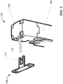
- FIG. 1 is a perspective view of an example locking switch 102 and corresponding locking tongue 108.
- the locking switch 102 is typically mounted to either the frame on which the gate is mounted or on the gate itself.
- the corresponding locking tongue 108 is mounted on the opposite gate component (either on the gate or on the frame) such that the tongue 108 aligns with an entry slot 110 on the locking switch 102.
- the locking tongue 108 is generally ring-shaped, having a square or circular engagement hole 112 configured to receive and engage with the switch's internal solenoid-driven locking bolt when the bolt is advanced (not shown in FIG. 1 ).
- the locking tongue 108 When the gate is in the closed position, the locking tongue 108 is received in the entry slot 110 of the locking switch 102. While the protected machine or automation system is in automatic mode or is running, the locking switch 102 actuates a solenoid-driven locking bolt upward through the engagement 112 of the locking tongue 108, preventing removal of the locking tongue 108 from the locking switch 102 and thereby preventing the gate from being opened. Some locking switches 102 are electrically connected to the machine cell's safety system such that the machine or automation system cannot be placed in automatic mode unless the locking tongue 108 is engaged with the locking switch 102.
- Example locking switch 102 comprises a main body 104 that houses the solenoid and retractable bolt (while retracted) and a attached head 106 on which the entry slot 110 is formed.
- Head 106 is removably attached to the body 104 and can be attached to the body 104 in a selected rotational orientation so that the entry slot 110 faces a selected one of three or four possible directions oriented at 90 increments.
- an installer or engineer may not have a priori knowledge of the direction from which the tongue 108 will approach the locking switch 102, which may depend on the available mounting options for the tongue 108 and the switch 102.
- the structural parameters of the locking switch 102 can limit available mounting options, or may require a labor-intensive mechanical reconfiguration of the locking switch 102 in order to accommodate the requirements of a given mounting scenario.
- one or more embodiments described herein provide a locking switch configured to accommodate multiple directions of approach of a corresponding locking tongue 108 without the need to rotate the head, body, or switch as a whole.
- multiple radio frequency identifier (RFID) coils are also installed in the head of the sensor, each of which is capable of detecting an RFID tag on the tongue when the tongue has been inserted into an entry slot.
- RFID radio frequency identifier
- FIGs. 2a, 2b, and 2c are right side, front, and left side views of an example locking switch 202 according to one or more embodiments.
- FIG. 3 is a perspective close-up view of the top of locking switch 202.
- locking switch 202 comprises a main body 210 that houses the solenoid, locking bolt mechanism, and other electrical and electronic components.
- a cable port 206 is formed on the body housing 210 to receive power and signal cabling that interfaces with the switch's internal circuitry.
- Switch 202 also comprises a head 208 mounted to the main body 210. In contrast to head 106 of switch 102, head 208 comprises three entry slots 204a, 204b, and 204c.
- a first entry slot 204b is formed on a front side of head 208, while entry slots 204a and 204c are formed on the right and left sides of head 208, respectively.
- This configuration supports three orthogonal directions of approach of a corresponding locking tongue without the need to rotate the head 208 relative to the body 210, or to rotate the switch 202 as a whole.
- Embodiments of locking switch 202 can include detection circuitry that detects when the tongue has been inserted into any of the three entry slots 204a, 204b, or 204c, indicating that the locking bolt can be advanced in order to properly engage with the locking tongue.
- this detection circuity can control an output signal (e.g. sent via a cable installed through cable port 206) that indicates whether the locking tongue is inserted into one of the entry slots 204a, 204b, or 204c.
- this output signal may be used to control when the locking bolt transitions from the retracted (unlocked) position to the advanced (locked) position.
- FIG. 4 is a perspective view of an example actuator assembly 402 that can be used with locking switch 202, and which includes an RFID tag 404 that can be detected by RFID coils housed in the switch 202 (to be discussed in more detail below).
- Actuator assembly 402 comprises a base 408 in which is mounted a locking tongue 412 (or locking key) configured to engage with any of the entry slots 204a, 204b, or 204c of locking switch 202.
- Mounting holes 414 are formed through base 408 and can be used in connection with mounting hardware to mount the actuator assembly 402 to a structure (e.g., the frame on which a safety gate is mounted or the gate itself).
- Locking tongue 412 is formed on one end of an actuating shaft 406, and the other end of actuating shaft 406 is installed within a recess 416 of base 408.
- tongue 412 has formed therein a substantially square bolt engagement hole 410 configured to receive the locking switch's locking bolt when the bolt is advanced, although bolt engagement holes of other shapes are also within the scope of one or more embodiments.
- RFID tag 404 is mounted in the tongue 412 within a circular mounting feature (e.g., a hole or recess) formed in the tongue 412 adjacent to the bolt engagement hole 410.
- RFID coils mounted in the locking switch's head 208 can detect the presence of the RFID tag 404 and thereby confirm that the tongue 412 is inserted into the locking switch 202 and that the locking bolt can be engaged.
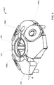
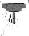
- FIG. 5a is a perspective view of the top of locking switch 202 with the casing of head 208 removed, revealing a bushing 502 within which is housed the solenoid-driven locking bolt that, when advanced, engages with the inserted tongue 412.
- a coil housing 504 is mounted above the locking bolt bushing 502 on the ceiling 514 of locking switch 202.
- Fig. 5b is a perspective view of the top of locking switch 202 with both the casing of head 208 and the coil housing 504 removed. Enclosed within the coil housing 504 are three RFID coils 506 electrically connected in series, each coil 506 corresponding to a different one of the three entry slots 204a, 204b, and 204c.
- each coil 506 is oriented above one of the entry slots 204a, 204b, and 204c to facilitate detection of the tongue's RFID tag 404.
- the series-connected RFID coils 506 are components of a detection circuit housed in the locking switch 202, which controls an output signal based on detection of the presence of the RFID tag 404.
- FIG. 6 is a perspective, cross-sectional view of a bobbin assembly 602 comprising bobbin 508 and coils 506a, 506b, and 506c.
- Bobbin 508 has a substantially round profile and a top surface (or coil mounting surface) that slants upward from its edge to its center, yielding a top surface having a degree of tilt ⁇ relative to the bottom surface (that is, the surface that mounts to the locking switch's housing).
- ⁇ may be approximately 38 degrees. However, other degrees of tilt are also within the scope of one or more embodiments.
- An opening 512 is formed in the center of bobbin 508 and is configured to receive the locking bolt when the bolt is advanced.
- RFID coils 506a, 506b, and 506c are mounted on the slanted top surface of bobbin 508.
- each RFID coil 504 is tilted relative to the plane of the ceiling 514 such that the coil's axis - and consequently the coil's sensing field - is directed outward from the center of the bobbin 508. Tilting the RFID coils 504 in this manner can increase the lateral sensing distance of each RFID coil 504, allowing the tongue's RFID tag 404 to be detected before the tongue 412 is fully inserted into the entry slot 204.
- This feature together with the relatively large size of the tongue's engagement hole 410, can promote a large degree of mechanical freedom when aligning the engagement hole with locking bolt, as discussed in more detail below.
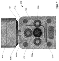
- FIG. 7 is a cross-sectional top view of locking switch 202 with the tongue 412 of actuator assembly 402 inserted into the front facing entry slot 204b.
- FIG. 8 is a perspective view depicting relative positions of the actuator assembly 402 and RFID coils 506a, 506b, and 506c when the tongue 412 is inserted into the front facing entry slot 204b (for clarity, FIGs. 7 and 8 depict RFID coils 506 as being oriented to reside in the same plane rather than being tilted; however, in some embodiments the RFID coils 506 will be tilted by bobbin 508 as shown in FIGs. 5b and 6 ).
- RFID coils 506a, 506b, and 506c are connected in series and are electrically driven by detection circuitry 802 inside the sensor's housing to generate three separate electromagnetic fields.
- This detection circuitry 802 includes an RFID transceiver that detects disturbances to any of the three electromagnetic fields due to the presence of RFID tag 404 within range of the electromagnetic field. Such disturbances modulate an RFID current signal into the detection circuitry 802, which detects the presence of the tongue 412 based on these current signal modulations.
- RFID coils 506a, 506b, and 506c are connected in series, disturbances to any of the three electromagnetic fields generated by the respective three coils 506 are detected by the RFID transceiver of detection circuitry 802.
- a single RFID transceiver can be used to detect entry of the tongue 412 into any of the three entry slots 204a, 204b, and 204c, mitigating the need for three separate RFID transceivers.
- This configuration can also yield a relatively fast response time, since the tongue's RFID tag 404 can be detected from multiple directions by monitoring only one signal, without the need to multiplex signals or analyze multiple signal lines.
- the middle RFID coil 506b can be flipped in polarity relative to the polarities of RFID coils 506a and 506c, partially cancelling the magnetic field in the center of coil 604 and reducing interfere of the RFID signal on the bolt detection signal.
- FIG. 9 is a top view of an example tongue component 906 that can be used in the actuator assembly 402 to prevent premature detection due to parasitic effects.
- tongue component 906 comprises a gap 904 that runs from the edge of RFID tag mounting hole 902 (in which the RFID tag 404 res ides) through the entire length of the articulating shaft 406, splitting the articulating shaft 406 along its lengthwise axis.
- Gap 904 is designed to mitigate potential paras itic effects of the metal tongue component 906 that could otherwise cause the tongue 412 to act as an antenna in the presence of the RFID coils' magnetic fields, resulting in premature detection of the tongue 412 before the tongue is inserted to a viable locking depth.
- This electrical configuration together with the mechanical design of the locking switch's head 208, affords a degree of installation flexibility by supporting three different directions of approach of the tongue 412 without the need to rotate head 208 or, in some cases, to re-orient the locking switch as a whole.
- This arrangement is supported by an electrical detection system that can detect entry of the tongue 412 from any of the multiple directions by monitoring a single electrical signal with one sensor.
- RFID coils 506 can be tilted outward by virtue of the slanted surface of bobbin 508 (see FIG. 6 ). This extends the sensing distance of each RFID coil 506 and allows the detection circuitry 802 to detect the tongue's RFID tag 404 before the tongue 412 is fully inserted into an entry slot 204. This extended detection distance can work in conjunction with an engagement hole 410 that is sized to be considerably larger than the locking bolt 702 to introduce a large degree of misalignment tolerance between the tongue 412 and the locking bolt 702.
- sizing the tongue's engagement hole 410 to be larger than the cross-sectional profile of the locking bolt 702 allows the locking bolt 702 to successfully engage with the tongue's engagement hole across a larger range of tongue insertion depths than would be possible if the engagement hole 410 was sized more closely to the locking bolt's profile. Since this design does not require the tongue 412 to be fully inserted into an entrance slot 204 before the locking bolt 702 can be engaged, the extended sensing distance that results from tilting of the RFID coils 506 as shown in FIG. 6 can facilitate detection of the RFID tag 404 at the earliest insertion position at which the locking bolt 702 can be safely advanced while ensuring reliable engagement with the engagement hole 410.
- a further degree of misalignment tolerance between the tongue 412 and the locking switch 202 can be achieved by designing the actuator assembly 402 such that the tongue 412 can articulate within the base 408 to a limited degree.
- tongue 412 is formed on one end of an articulating shaft 406 that is mounted within a recess 416 of base 408.
- the shaft 406 is unrestrained in the x-y plane (that is, the plane parallel with the front face of the base 408), allowing the shaft 406 and tongue 412 to pivot away from its normal axis relative to base 408 within the bounds of recess 416.
- the shaft 406 may also be afforded limited sliding movement along the z-axis (perpendicular to the face of base 408). Designing the actuator assembly 402 to permit a limited degree of tongue articulation in this manner further increases the misalignment tolerance between the tongue 412 and the locking switch 202, allowing the tongue 412 to be inserted into an entry slot 204 and engaged with the locking bolt 503 even if the tongue 412 is imperfectly aligned with these switch components.
- bobbin assembly 602 may also include an inductive coil 604 mounted within the opening 512 of the bobbin 508.
- Coil 604 is part of an LC tank circuit housed within the switch housing used to detect and confirm that the locking bolt 702 has been advanced.
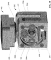
- FIG. 10 is a cross-sectional view of the locking switch's head 208 with actuator assembly 402 inserted and engaged with the locking switch.
- the bobbin 508 is omitted from this view to illustrate the positions of RFID coils 506 and inductive coil 604.
- An LC tank circuit including inductive coil 604 in parallel with a capacitor acts as an inductive sensor that detects when the locking bolt 702 is in the advanced position.
- the circuit can drive an alternating current through the coil 604, where the frequency of the current is a function of the inductance of the coil 604.
- Inductive coil 604 resides along the edge of the bobbin's central opening 512 so that locking bolt 702 passes through the coil 604 when advanced to the locked pos ition. While locking bolt 702 is in the advanced (locked) position, the presence of the metal locking bolt 702 within the coil's magnetic field changes the inductance of the coil 604, and thus changes the frequency of the current signal. This change in the frequency of the current signal is detected by the LC tank circuit which generates a confirmation signal in response, indicating that the locking bolt 702 is in the advanced position.
- inductive coil 604 and its associated LC tank circuit provide a noncontact method for confirming that locking bolt 702 has properly advanced and engaged with tongue 412.
- the use of an inductive sensor allows the position of locking bolt 702 to be detected without the use of a magnet or optical sensing, yielding a robust solution for bolt detection.
- locking switch 202 that include both inductive coil 604 for detecting the locking bolt 702 and RFID coils 506 detecting the locking tongue 412
- different types of metal can be used for the tongue 412 and the bolt 702 to ensure that the inductive coil 604 reliably detects locking bolt 702 without detecting the locking tongue 412.
- the metal used to fabricate the locking bolt 702 can be chosen as one having intrinsic properties that cause the inductive coil 604 to induce a greater frequency shift than those of the metal chosen for the locking tongue 412.
- locking tongue 412 can be made of 400 series stainless steel (e.g., 416, 410, etc.), while locking bolt 702 can be made from 300 series stainless steel.
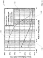
- 11 is a graph 1102 that plots sensor inductance shift as a function of sensor frequency for a variety of materials.
- the amount of sensor inductance shift is a function of intrinsic properties of the respective materials.
- the horizontal line 1104 represents the lack of frequency shift when no metal is present (free space).
- the top line 1102 represents the inductance shift of stainless steel 416
- line 1106 represents the inductance shift of stainless steel 304
- the bottom line represents the inductance shift of aluminum 1100.
- the relative inductance shifts modeled by graph 1102 can be used to find an operating frequency for the inductive sensor (including inductive coil 604) that maximizes detection of locking bolt 702 while minimizing detection of the locking tongue 412; e.g., by selecting a sensor operating frequency corresponding to a sufficiently large inductance shift for stainless steel 416 (line 1102) to ensure reliable detection of the locking bolt 702, and a sufficiently small inductance shift for stainless steel 304 (line 1106) to ensure that the locking tongue 412 is not detected by the inductive sensor.
- the tilting of the RFID coils 506 due to the slanted surface of bobbin 508 can minimize the risk of interference between the RFID coils 506 and inductive coil 604, since the RFID coils are tilted relative to the inductive coil causing the sensing fields of the RFID coils to be directed away from that of the inductive coil.
- the RFID coils 506 and inductive coil 604 can be operated at different operating frequencies (e.g., 500kHz for the inductive coil 604 and 125kHz for the RFID coils 506) to further minimize the risk of interference between the two sensing systems.
- Industrial safety applications can be made more robust if their associated locking switches are capable of validating proper operation of their locking bolts. This can include validating that the locking switch is capable of reliably confirming the actual position of the locking bolt. Some locking switches may perform this validation by advancing the locking bolt to the locked position and then retracting the bolt back to the unlocked position during a test sequence, and confirming that the bolt detection signal was properly received. However, since this validation approach requires the locking bolt to be actuated, normal operation of the switch must be interrupted in order to validate locking bolt detection. If the locking switch is currently holding a safety gate in the closed and locked position, actuating the locking bolt during this test sequence causes the safety gate to become temporarily unlocked, creating a potential safety hazard.
- FIG. 12 is a generalized diagram of an example validation circuit that includes diagnostic circuitry capable of confirming the locking switch's bolt detection capability without interrupting the function of the switch 202.
- the LC tank circuit 1212 used to detect the locking bolt 702 while in its advanced (locking) position comprises the inductive coil 604 (which can mounted in bobbin 508 in some embodiments, as discussed above) and a capacitor 1210 connected in parallel.
- An inductance-to-digital converter (LDC) 1204 (or another type of conversion component) is connected to the nodes of LC tank circuit 1212 and translates the measured frequency of the current signal generated by the LC circuit 1212 to digital data that is placed on a data bus 1214 (e.g., an I2C bus or another type of data bus).
- This frequency signal is indicative of the inductance of coil 604, which in turn is a function of the presence or absence of locking bolt 702 within the magnetic field of inductive coil 604.
- FIG. 12 depicts an LDC 1204 as the conversion component used to translate the current signal frequency to digital data, other types of conversion components can also be used to generate a digital value proportionate to the current signal frequency in some embodiments.
- a master controller 1202 on the data bus 1214 monitors the digital frequency signal on the data bus 1214 and confirms that the locking bolt 702 has properly advanced - or has properly retracted - based on measured changes to the digital frequency value.
- some embodiments may also include a watchdog controller 1208 that is tied to the data bus 1214 and performs redundant monitoring of the digital frequency signal.
- both the master controller 1202 and the watchdog controller 1208 may perform parallel independent monitoring of the digital frequency signal and collectively confirm the position of the locking bolt 702 only if both controllers 1202 and 1208 reach the same conclusion.
- the master controller 1202 and/or the watchdog controller generates a confirmation signal in response to this confirmation that the locking bolt 702 has advanced.
- a diagnostic capacitor 1216 is connected to the LC tank circuit 1212 via a diagnostic switch 1206 (e.g., a solid state switching device). Diagnostic capacitor 1216 remains isolated from the LC tank circuit 1212 while the diagnostic switch 1206 is disabled. During a diagnostic sequence initiated and controlled by the master controller 1202, the diagnostic switch 1206 is enabled (e.g., by a signal applied to the diagnostic switch's Enable input by master controller 1202), which causes the diagnostic capacitor 1216 to be electrically connected to the LC tank circuit 1212 in parallel with capacitor 1210.
- a diagnostic switch 1206 e.g., a solid state switching device. Diagnostic capacitor 1216 remains isolated from the LC tank circuit 1212 while the diagnostic switch 1206 is disabled.
- the diagnostic switch 1206 is enabled (e.g., by a signal applied to the diagnostic switch's Enable input by master controller 1202), which causes the diagnostic capacitor 1216 to be electrically connected to the LC tank circuit 1212 in parallel with capacitor 1210.
- the capacitance of diagnostic capacitor 1216 is sized such that connecting the diagnostic capacitor 1216 in parallel with tank capacitor 1210 creates a shift in the frequency of the current signal through the LC tank circuit 1212 that is roughly the equivalent of the frequency shift caused by the presence of the locking bolt 702 within the magnetic field of coil 604. That is, whereas advancement of locking bolt 702 to the locked position changes the inductance of coil 604 in a manner that alters the frequency of the current through the LC tank circuit 1212 by a predictable frequency shift magnitude, connecting diagnostic capacitor 1216 to the LC tank circuit 1212 (by enabling diagnostic switch 1206) changes the capacitance of the LC tank circuit 1212 in a manner that alters the frequency by a substantially equal frequency shift magnitude.
- master controller 1202 can enable the diagnostic switch 1206 and monitor the digital frequency value generated by the LDC 1204 to verify that the frequency value changes as expected. For example, during normal operation of the locking switch 202 the master controller 1202 can monitor the digital frequency value on bus 1214 and, in response to determining that the frequency value changes by a defined frequency shift magnitude indicative of the presence of the locking bolt within the coil's magnetic field, generate a confirmation signal indicating that the locking bolt 702 has been advanced.
- the defined frequency shift magnitude may be defined as a valid frequency shift range to allow for small frequency variations.
- master controller 1202 can enable diagnostic switch 1106 and, in response to determining that the digital frequency value shifts by the defined frequency shift magnitude (within a defined tolerance) within an expected time duration after enabling the diagnostic switch 1206, confirm that the locking bolt validation system is operating properly and is capable of reliable detecting the state of the locking bolt 702. Alternatively, if the master controller 1202 determines that the digital frequency value has not shifted by the defined frequency shift magnitude within the defined time duration after enabling the diagnostic switch 1206, the master controller 1202 generates an error signal.
- the error signal may include an error message rendered on a client device indicating that the locking bolt validation system is not working properly, or may be an error signal sent to an external safety or control system.
- This diagnostic sequence can be performed regardless of whether the locking bolt 702 is currently advanced or retracted, and does not require the locking bolt 702 to be physically actuated in order to validate the LC tank circuit 1212 and its associated LDC 1204.
- any control outputs from the locking switch 202 that would otherwise be generated in response to detecting that the locking bolt has been advanced are disabled to prevent false indications being sent to external control or safety systems.
- inductive sensor LC tank circuit 1212
- diagnostic circuitry requires only a single sensor to confirm the position of the locking bolt 702 in a robust and reliable manner.
- FIG. 13 is a generalized diagram of another example embodiment of locking bolt validation circuit including diagnostic circuitry.
- This example embodiment adds a separate diagnostic controller 1302 so that operation of the master controller 1202 and watchdog controller 1208 is included in the scope of validation.
- the enable signal that controls the state of diagnostic switch 1206 is generated by this new diagnostic controller 1302 rather than by master controller 1202.
- Diagnostic controller 1302 validates operation of the locking bolt detection circuitry by monitoring outputs of the master controller 1202 and watchdog controller 1208 rather than by monitoring the digital frequency signal directly as in the embodiment depicted in FIG. 12 .
- diagnostic controller 1302 enables switch 1206 and monitors the detection signals generated master controller 1202 and watchdog controller 1208.
- Each controller 1202 and 1208 generates its detection signal in response to detecting the expected shift in the digital frequency signal caused by switching the diagnostic capacitor 1216 to the LC tank circuit 1212. If the detection signals from both the master controller 1202 and watchdog controller 1208 indicate that the expected frequency shift has been detected within a defined time duration after generating the enable signal, diagnostic controller 1302 determines that the locking bolt detection circuitry is operating properly.
- diagnostic controller 1302 determines that the locking bolt detection circuitry is not functioning properly and generates an error signal.
- the various sensing and validation features described herein can be used collectively in a single locking switch in some embodiments.
- Other embodiments may comprise locking switches that incorporate only a subset of the disclosed sensing and validation features.
- some embodiments of the disclosed locking switch 202 may include both RFID coils 506 and inductive coil 604.
- Other embodiments may incorporate only the RFID coils 506 without including inductive coil 604, while still other embodiments may include only the inductive coil 604 without including RFID coils 506.
- embodiments of locking switch 202 have been described herein as including three locking tongue entry slots 204, some embodiments may include more than three tongue entry slots 204 (and corresponding RFID coils 506) without departing from the scope of one or more embodiments.
- Some embodiments may also comprise only two tongue entry slots and corresponding RFID coils 506.
- FIGs. 14-15 illustrate methodologies in accordance with one or more embodiments of the subject application. While, for purposes of simplicity of explanation, the methodologies shown herein are shown and described as a series of acts, it is to be understood and appreciated that the subject innovation is not limited by the order of acts, as some acts may, in accordance therewith, occur in a different order and/or concurrently with other acts from that shown and described herein. For example, those skilled in the art will understand and appreciate that a methodology could alternatively be represented as a series of interrelated states or events, such as in a state diagram. Moreover, not all illustrated acts may be required to implement a methodology in accordance with the innovation.
- interaction diagram(s) may represent methodologies, or methods, in accordance with the subject disclosure when disparate entities enact disparate portions of the methodologies.
- two or more of the disclosed example methods can be implemented in combination with each other, to accomplish one or more features or advantages described herein.
- FIG. 14 is an example methodology 1400 for detecting insertion of a locking tongue of an actuator assembly into an industrial locking switch from any of three different directions of approach.
- a determination is made as to whether an RFID tag mounted on a locking tongue of an actuator assembly is detected by any of a first RFID coil located inside a first entry slot of an industrial locking switch, a second RFID coil located inside a second entry slot of the industrial locking switch, or a third RFID coil located inside a third entry slot of the industrial locking switch.
- step 1402 repeats until any of the three RFID coils detects the RFID tag (YES at step 1402), causing the methodology to proceed to step 1404, where a confirmation signal indicating that the locking tongue has been inserted into one of the entry slots is generated.
- the confirmation signal may be an interlock signal sent to an external or internal control system that controls the position of the locking switch's locking bolt, such that the locking bolt is engaged only if the confirmation signal is received.
- the first, second, and third RFID coils can be electrically connected together in series, and the determinations as to whether the RFID tag has been detected by any of the three RFID coils can be made by detection circuitry based on measured modulations induced on a current through the coils as a result of disturbances to the coils' electromagnetic fields by the RFID tag.
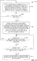
- FIG. 15 is an example methodology 1500 for validating correct operation of an inductive sensor used to detect the position of the locking bolt of an industrial locking switch. Initially, at 1502, a position of the locking bolt is detected based on measurement of a frequency shift of the inductive sensor's current, where this frequency shift is caused by presence of the locking bolt within a magnetic field of the inductive sensor.
- the inductive sensor may comprise an LC tank circuit having an inductive coil positioned such that the locking bolt enters the inductive coil's magnetic field when advanced to the locked position.
- Steps 1508 and 1510 repeat until either the frequency shift is detected at step 1508 (thereby validating operation of the inductive sensor) or the defined time duration elapses at step 1510. If the expected frequency shift is not detected before the defined time duration has elapsed (YES at step 1510), the methodology proceeds to step 1512, where an error signal is generated indicating that operation of the inductive sensor cannot be validated.
- Embodiments, systems, and components described herein, as well as industrial control systems and industrial automation environments in which various aspects set forth in the subject specification can be carried out can include computer or network components such as servers, clients, programmable logic controllers (PLCs), automation controllers, communications modules, mobile computers, wireless components, control components and so forth which are capable of interacting across a network.
- Computers and servers include one or more processors-electronic integrated circuits that perform logic operations employing electric signals--configured to execute instructions stored in media such as random access memory (RAM), read only memory (ROM), a hard drives, as well as removable memory devices, which can include memory sticks, memory cards , flash drives, external hard drives, and so on.
- the term PLC or automation controller as used herein can include functionality that can be shared across multiple components, systems, and/or networks.
- one or more PLCs or automation controllers can communicate and cooperate with various network devices across the network- This can include substantially any type of control, communications module, computer, Input/Output (I/O) device, sensor, actuator, instrumentation, and human machine interface (HMI) that communicate via the network, which includes control, automation, and/or public networks.
- the PLC or automation controller can also communicate to and control various other devices such as standard or safety-rated I/O modules including analog, digital, programmed/intelligent I/O modules, other programmable controllers, communications modules, sensors, actuators, output devices, and the like.
- the network can include public networks such as the internet, intranets, and automation networks such as Common Industrial Protocol (CIP) networks including DeviceNet, ControlNet, and Ethernet/IP. Other networks include Ethernet, DH/DH+, Remote I/O, Fieldbus, Modbus, Profibus, CAN, wireless networks, serial protocols, near field communication (NFC), Bluetooth, and so forth.
- the network devices can include various possibilities (hardware and/or software components). These include components such as switches with virtual local area network (VLAN) capability, LANs, WANs, proxies, gateways, routers, firewalls, virtual private network (VPN) devices, servers, clients, computers, configuration tools, monitoring tools, and/or other devices.
- VLAN virtual local area network
- WANs wide area network
- proxies gateways
- routers virtual private network
- VPN virtual private network
- FIGs. 16 and 17 are intended to provide a brief, general description of a suitable environment in which the various aspects of the disclosed subject matter may be implemented.
- an example environment 1610 for implementing various aspects of the aforementioned subject matter includes a computer 1612.
- the computer 1612 includes a processing unit 1614, a system memory 1616, and a system bus 1618.
- the system bus 1618 couples system components including, but not limited to, the system memory 1616 to the processing unit 1614.
- the processing unit 1614 can be any of various available processors. Multi-core microprocessors and other multiprocessor architectures also can be employed as the processing unit 1614.
- the system bus 1618 can be any of several types of bus structure(s) including the memory bus or memory controller, a peripheral bus or external bus, and/or a local bus using any variety of available bus architectures including, but not limited to, 8-bit bus, Industrial Standard Architecture (ISA), Micro-Channel Architecture (MSA), Extended ISA (EISA), Intelligent Drive Electronics (IDE), VESA Local Bus (VLB), Peripheral Component Interconnect (PCI), Universal Serial Bus (USB), Advanced Graphics Port (AGP), Personal Computer Memory Card International Association bus (PCMCIA), and Small Computer Systems Interface (SCSI).
- ISA Industrial Standard Architecture
- MSA Micro-Channel Architecture
- EISA Extended ISA
- IDE Intelligent Drive Electronics
- VLB VESA Local Bus
- PCI Peripheral Component Interconnect
- USB Universal Serial Bus
- AGP Advanced Graphics Port
- PCMCIA Personal Computer Memory Card International Association bus
- SCSI Small Computer Systems Interface
- the system memory 1616 includes volatile memory 1620 and nonvolatile memory 1622.
- the basic input/output system (BIOS) containing the basic routines to transfer information between elements within the computer 1612, such as during start-up, is stored in nonvolatile memory 1622.
- nonvolatile memory 1622 can include read only memory (ROM), programmable ROM (PROM), electrically programmable ROM (EPROM), electrically erasable PROM (EEPROM), or flash memory.
- Volatile memory 1620 includes random access memory (RAM), which acts as external cache memory.
- RAM is available in many forms such as synchronous RAM (SRAM), dynamic RAM (DRAM), synchronous DRAM (SDRAM), double data rate SDRAM (DDR SDRAM), enhanced SDRAM (ESDRAM), Synchlink DRAM (SLDRAM), and direct Rambus RAM (DRRAM).
- SRAM synchronous RAM
- DRAM dynamic RAM
- SDRAM synchronous DRAM
- DDR SDRAM double data rate SDRAM
- ESDRAM enhanced SDRAM
- SLDRAM Synchlink DRAM
- DRRAM direct Rambus RAM
- Disk storage 1624 includes, but is not limited to, devices like a magnetic disk drive, floppy disk drive, tape drive, Jaz drive, Zip drive, LS-100 drive, flash memory card, or memory stick.
- disk storage 1624 can include storage media separately or in combination with other storage media including, but not limited to, an optical disk drive such as a compact disk ROM device (CD-ROM), CD recordable drive (CD-R Drive), CD rewritable drive (CD-RW Drive) or a digital versatile disk ROM drive (DVD-ROM).
- an optical disk drive such as a compact disk ROM device (CD-ROM), CD recordable drive (CD-R Drive), CD rewritable drive (CD-RW Drive) or a digital versatile disk ROM drive (DVD-ROM).
- a removable or non-removable interface is typically used such as interface 1626.
- FIG. 16 describes software that acts as an intermediary between users and the basic computer resources described in suitable operating environment 1610.
- Such software includes an operating system 1628.
- Operating system 1628 which can be stored on disk storage 1624, acts to control and allocate resources of the computer 1612.
- System applications 1630 take advantage of the management of resources by operating system 1628 through program modules 1632 and program data 1634 stored either in system memory 1616 or on disk storage 1624. It is to be appreciated that one or more embodiments of the subject disclosure can be implemented with various operating systems or combinations of operating systems.
- Input devices 1636 include, but are not limited to, a pointing device such as a mouse, trackball, stylus, touch pad, keyboard, microphone, joystick, game pad, satellite dish, scanner, TV tuner card, digital camera, digital video camera, web camera, and the like. These and other input devices connect to the processing unit 1614 through the system bus 1618 via interface port(s) 1638.
- Interface port(s) 1638 include, for example, a serial port, a parallel port, a game port, and a universal serial bus (USB).
- Output device(s) 1640 use some of the same type of ports as input device(s) 1636.
- a USB port may be used to provide input to computer 1612, and to output information from computer 1612 to an output device 1640.
- Output adapters 1642 are provided to illustrate that there are some output devices 1640 like monitors, speakers, and printers, among other output devices 1640, which require special adapters.
- the output adapters 1642 include, by way of illustration and not limitation, video and sound cards that provide a means of connection between the output device 1640 and the system bus 1618. It should be noted that other devices and/or systems of devices provide both input and output capabilities such as remote computer(s) 1644.
- Computer 1612 can operate in a networked environment using logical connections to one or more remote computers, such as remote computer(s) 1644.
- the remote computer(s) 1644 can be a personal computer, a server, a router, a network PC, a workstation, a microprocessor based appliance, a peer device or other common network node and the like, and typically includes many or all of the elements described relative to computer 1612. For purposes of brevity, only a memory storage device 1646 is illustrated with remote computer(s) 1644.
- Remote computer(s) 1644 is logically connected to computer 1612 through a network interface 1648 and then physically connected via communication connection 1650.
- Network interface 1648 encompasses communication networks such as local-area networks (LAN) and wide-area networks (WAN).
- LAN technologies include Fiber Distributed Data Interface (FDDI), Copper Distributed Data Interface (CDDI), Ethernet/IEEE 802.3, Token Ring/IEEE 802.5 and the like.
- WAN technologies include, but are not limited to, point-to-point links, circuit switching networks like Integrated Services Digital Networks (ISDN) and variations thereon, packet switching networks, and Digital Subscriber Lines (DSL).
- ISDN Integrated Services Digital Networks
- DSL Digital Subscriber Lines
- Network interface 1648 can also encompass near field communication (NFC) or Bluetooth communication.
- Communication connection(s) 1650 refers to the hardware/software employed to connect the network interface 1648 to the system bus 1618. While communication connection 1650 is shown for illustrative clarity inside computer 1612, it can also be external to computer 1612.
- the hardware/software necessary for connection to the network interface 1648 includes, for exemplary purposes only, internal and external technologies such as, modems including regular telephone grade modems, cable modems and DSL modems, ISDN adapters, and Ethernet cards.
- FIG. 17 is a schematic block diagram of a sample computing environment 1700 with which the disclosed subject matter can interact.
- the sample computing environment 1700 includes one or more client(s) 1702.
- the client(s) 1702 can be hardware and/or software (e.g., threads, processes, computing devices).
- the sample computing environment 1700 also includes one or more server(s) 1704.
- the server(s) 1704 can also be hardware and/or software (e.g., threads, processes, computing devices).
- the servers 1704 can house threads to perform transformations by employing one or more embodiments as described herein, for example.
- One possible communication between a client 1702 and servers 1704 can be in the form of a data packet adapted to be transmitted between two or more computer processes.
- the sample computing environment 1700 includes a communication framework 1706 that can be employed to facilitate communications between the client(s) 1702 and the server(s) 1704.
- the client(s) 1702 are operably connected to one or more client data store(s) 3208 that can be employed to store information local to the client(s) 1702.
- the server(s) 1704 are operably connected to one or more server data store(s) 1710 that can be employed to store information local to the servers 1704.
- the terms (including a reference to a "means") used to describe such components are intended to correspond, unless otherwise indicated, to any component which performs the specified function of the described component (e.g., a functional equivalent), even though not structurally equivalent to the disclosed structure, which performs the function in the herein illustrated exemplary aspects of the disclosed subject matter.
- the disclosed subject matter includes a system as well as a computer-readable medium having computer-executable instructions for performing the acts and/or events of the various methods of the disclosed subject matter.
- exemplary is used to mean serving as an example, instance, or illustration. Any aspect or design described herein as "exemplary” is not necessarily to be construed as preferred or advantageous over other aspects or designs. Rather, use of the word exemplary is intended to present concepts in a concrete fashion.
- Computer readable media can include but are not limited to magnetic storage devices (e.g., hard disk, floppy disk, magnetic strips...), optical disks [e.g., compact disk (CD), digital versatile disk (DVD)...], smart cards, and flash memory devices (e.g., card, stick, key drive).
- magnetic storage devices e.g., hard disk, floppy disk, magnetic strips
- optical disks e.g., compact disk (CD), digital versatile disk (DVD)...
- smart cards e.g., card, stick, key drive
Landscapes
- Engineering & Computer Science (AREA)
- Physics & Mathematics (AREA)
- General Physics & Mathematics (AREA)
- General Engineering & Computer Science (AREA)
- Mechanical Engineering (AREA)
- Power Engineering (AREA)
- Radar, Positioning & Navigation (AREA)
- Remote Sensing (AREA)
- Switches That Are Operated By Magnetic Or Electric Fields (AREA)
- Train Traffic Observation, Control, And Security (AREA)
- Lock And Its Accessories (AREA)
Abstract
Description
- The subject matter disclosed herein relates generally to industrial safety locks, and, more particularly, to internal locking switch sensing and diagnostics.
- The following presents a simplified summary in order to provide a basic understanding of some aspects described herein. This summary is not an extensive overview nor is intended to identify key/critical elements or to delineate the scope of the various aspects described herein. Its sole purpose is to present some concepts in a simplified form as a prelude to the more detailed description that is presented later.
- In one or more embodiments, a locking switch is provided, comprising a solenoid-driven locking bolt configured to engage with an engagement hole of a locking tongue when advanced to a locking position; and an inductive sensor system configured to detect that the locking bolt has advanced to the locking position, wherein the inductive sensor system comprises a tank circuit comprising an inductive coil and a capacitor, the inductive coil oriented to receive the locking tongue when the locking tongue is advanced to the locking position, a converter configured to convert a frequency of a current signal on the tank circuit to a digital frequency value, and a master controller configured to generate a lock detection signal in response to determining that a shift in the digital frequency value corresponds to an expected frequency shift of the current signal induced by the inductive coil in response to advancement of the locking bolt; and a diagnostic system configured to confirm operation of the inductive sensor system, the diagnostic system comprising a diagnostic capacitor and a diagnostic switch configured to connect the diagnostic capacitor to the tank circuit in parallel with the capacitor.
- Also, a system for sensing a position of a locking bolt of an industrial locking switch is provided, comprising an inductive circuit comprising an inductive coil and a capacitor electrically connected in parallel, wherein the inductive coil is positioned to receive a locking bolt of an industrial locking switch when the locking bolt is transitioned to a lock position; a converter configured to convert a frequency of a current signal on the inductive circuit to a digital frequency value; a master controller configured to generate a bolt detection signal in response to determining that the digital frequency value changes by an amount equal to or substantially equal to a defined frequency shift corresponding to a frequency shift induced by the inductive coil in response to presence of the locking bolt within the inductive coil's magnetic field; and a diagnostic system configured to validate operation of the inductive circuit and the converter, the diagnostic system comprising a diagnostic capacitor and a diagnostic switch configured to electrically connect the diagnostic capacitor to the inductive circuit in parallel with the capacitor.
- Also, method for validating operation of a locking bolt detection system is provided, comprising in response to initiation of a diagnostic test, connecting a diagnostic capacitor in parallel with a capacitor of an inductive sensing circuit configured to detect that a locking bolt of an industrial locking switch has advanced to a locking position, wherein the inductive sensing circuit comprises the capacitor and an inductive coil; and in response to determining that a frequency of a current signal through the inductive sensing circuit does not change, within a defined duration after the connecting of the diagnostic capacitor, by an amount equal to or substantially equal to a frequency shift caused by presence of the locking bolt in the inductive coil's magnetic field, generating an error message indicating that the inductive sensing circuit is not operating correctly.
- To the accomplishment of the foregoing and related ends, certain illustrative aspects are described herein in connection with the following description and the annexed drawings. These aspects are indicative of various ways which can be practiced, all of which are intended to be covered herein. Other advantages and novel features may become apparent from the following detailed description when considered in conjunction with the drawings.
-
-
FIG. 1 is a perspective view of an example locking switch and corresponding locking tongue. -
FIG. 2a is a right side view of an example locking switch. -
FIG. 2b is a front side view of the example locking switch. -
FIG. 2c is a left side view of the example locking switch. -
FIG. 3 is a perspective close-up view of the top of an example locking switch. -
FIG. 4 is a perspective view of an example actuator assembly that includes an RFID tag that can be detected by RFID coils housed in a locking switch. -
FIG. 5a is a perspective view of the top of a locking switch with the casing of the switch's head removed, revealing the switch's solenoid-driven locking bolt. -
FIG. 5b is a perspective view of the top of an example locking switch with both the casing of the switch's head and the switch's coil housing removed. -
FIG. 6 is a perspective, cross-sectional view of a bobbin assembly. -
FIG. 7 is a cross-sectional top view of a locking switch with a locking tongue inserted into the switch's front facing entry slot. -
FIG. 8 is a perspective view depicting relative positions of an actuator assembly and RFID coils when the actuator assembly's locking tongue is inserted into an entry slot of a locking switch. -
FIG. 9 is a top view of an example tongue component that can be used in an actuator assembly to prevent premature detection due to parasitic effects. -
FIG. 10 is a cross-sectional view of a locking switch's head with an actuator assembly inserted and engaged with the locking switch. -
FIG. 11 is a graph that plots sensor inductance shift as a function of sensor frequency for a variety of materials. -
FIG. 12 is a generalized diagram of an example validation circuit that includes diagnostic circuitry capable of confirming the locking switch's bolt detection capability without interrupting the function of the switch. -
FIG. 13 is a generalized diagram of another example embodiment of a locking bolt validation circuit including diagnostic circuitry. -
FIG. 14 is a flowchart of an example methodology for detecting insertion of a locking tongue of an actuator assembly into an industrial locking switch from any of three different directions of approach. -
FIG. 15 is a flowchart of an example methodology for validating correct operation of an inductive sensor used to detect the position of the locking bolt of an industrial locking switch. -
FIG. 16 is an example computing environment. -
FIG. 17 is an example networking environment. - The subject disclosure is now described with reference to the drawings, wherein like reference numerals are used to refer to like elements throughout. In the following description, for purposes of explanation, numerous specific details are set forth in order to provide a thorough understanding thereof. It may be evident, however, that the subject disclosure can be practiced without these specific details. In other instances, well-known structures and devices are shown in block diagram form in order to facilitate a description thereof.
- In addition, the term "or" is intended to mean an inclusive "or" rather than an exclusive "or." That is, unless specified otherwise, or clear from the context, the phrase "X employs A or B" is intended to mean any of the natural inclusive permutations. That is, the phrase "X employs A or B" is satisfied by any of the following instances: X employs A; X employs B; or X employs both A and B. In addition, the articles "a" and "an" as used in this application and the appended claims should generally be construed to mean "one or more" unless specified otherwise or clear from the context to be directed to a singular form.
- Furthermore, the term "set" as employed herein excludes the empty set; e.g., the set with no elements therein. Thus, a "set" in the subject disclosure includes one or more elements or entities. As an illustration, a set of controllers includes one or more controllers; a set of holes includes one or more holes; etc.
- Various aspects or features will be presented in terms of systems that may include a number of devices, components, modules, and the like. It is to be understood and appreciated that the various systems may include additional devices, components, modules, etc. and/or may not include all of the devices, components, modules etc. discussed in connection with the figures. A combination of these approaches also can be used.
- Many industrial machines, robots, or automation systems are protected by safety guarding or fencing that surrounds the hazardous area, forming a protected cell. This safety fencing typically includes a lockable safety gate to allow operator access to the protected area only while the machine or system is not operating and is otherwise in a safe state. Solenoid-driven locking switches are often used to lock these safety gates in the closed position while the protected machine or system is operating in automatic mode and all associated safety devices are in their safe statuses, thereby preventing operator access to the hazardous area while the machine is running.
-
FIG. 1 is a perspective view of anexample locking switch 102 andcorresponding locking tongue 108. Thelocking switch 102 is typically mounted to either the frame on which the gate is mounted or on the gate itself. Thecorresponding locking tongue 108 is mounted on the opposite gate component (either on the gate or on the frame) such that thetongue 108 aligns with anentry slot 110 on thelocking switch 102. Thelocking tongue 108 is generally ring-shaped, having a square orcircular engagement hole 112 configured to receive and engage with the switch's internal solenoid-driven locking bolt when the bolt is advanced (not shown inFIG. 1 ). - When the gate is in the closed position, the
locking tongue 108 is received in theentry slot 110 of thelocking switch 102. While the protected machine or automation system is in automatic mode or is running, thelocking switch 102 actuates a solenoid-driven locking bolt upward through theengagement 112 of thelocking tongue 108, preventing removal of thelocking tongue 108 from thelocking switch 102 and thereby preventing the gate from being opened. Somelocking switches 102 are electrically connected to the machine cell's safety system such that the machine or automation system cannot be placed in automatic mode unless thelocking tongue 108 is engaged with thelocking switch 102. -
Example locking switch 102 comprises amain body 104 that houses the solenoid and retractable bolt (while retracted) and a attachedhead 106 on which theentry slot 110 is formed.Head 106 is removably attached to thebody 104 and can be attached to thebody 104 in a selected rotational orientation so that theentry slot 110 faces a selected one of three or four possible directions oriented at 90 increments. - In some installation scenarios, an installer or engineer may not have a priori knowledge of the direction from which the
tongue 108 will approach thelocking switch 102, which may depend on the available mounting options for thetongue 108 and theswitch 102. In other scenarios, even if the direction of approach is known, it may be necessary to rotate theswitch 102, or to rotate thehead 106 relative to the switch, so that theentry slot 110 faces the direction from which thetongue 108 will approach. The structural parameters of the lockingswitch 102 can limit available mounting options, or may require a labor-intensive mechanical reconfiguration of the lockingswitch 102 in order to accommodate the requirements of a given mounting scenario. - To address these and other issues, one or more embodiments described herein provide a locking switch configured to accommodate multiple directions of approach of a
corresponding locking tongue 108 without the need to rotate the head, body, or switch as a whole. To facilitate detection of the tongue from each of these multiple directions, multiple radio frequency identifier (RFID) coils are also installed in the head of the sensor, each of which is capable of detecting an RFID tag on the tongue when the tongue has been inserted into an entry slot. -
FIGs. 2a, 2b, and 2c are right side, front, and left side views of anexample locking switch 202 according to one or more embodiments.FIG. 3 is a perspective close-up view of the top of lockingswitch 202. Similar toexample switch 102, lockingswitch 202 comprises amain body 210 that houses the solenoid, locking bolt mechanism, and other electrical and electronic components. Acable port 206 is formed on thebody housing 210 to receive power and signal cabling that interfaces with the switch's internal circuitry. Switch 202 also comprises ahead 208 mounted to themain body 210. In contrast to head 106 ofswitch 102,head 208 comprises threeentry slots first entry slot 204b is formed on a front side ofhead 208, whileentry slots head 208, respectively. This configuration supports three orthogonal directions of approach of a corresponding locking tongue without the need to rotate thehead 208 relative to thebody 210, or to rotate theswitch 202 as a whole. - Embodiments of locking
switch 202 can include detection circuitry that detects when the tongue has been inserted into any of the threeentry slots entry slots -
FIG. 4 is a perspective view of anexample actuator assembly 402 that can be used with lockingswitch 202, and which includes anRFID tag 404 that can be detected by RFID coils housed in the switch 202 (to be discussed in more detail below).Actuator assembly 402 comprises a base 408 in which is mounted a locking tongue 412 (or locking key) configured to engage with any of theentry slots switch 202. Mountingholes 414 are formed throughbase 408 and can be used in connection with mounting hardware to mount theactuator assembly 402 to a structure (e.g., the frame on which a safety gate is mounted or the gate itself). - Locking
tongue 412 is formed on one end of anactuating shaft 406, and the other end of actuatingshaft 406 is installed within arecess 416 ofbase 408. In the example depicted inFIG. 4 ,tongue 412 has formed therein a substantially squarebolt engagement hole 410 configured to receive the locking switch's locking bolt when the bolt is advanced, although bolt engagement holes of other shapes are also within the scope of one or more embodiments.RFID tag 404 is mounted in thetongue 412 within a circular mounting feature (e.g., a hole or recess) formed in thetongue 412 adjacent to thebolt engagement hole 410. Whentongue 412 is inserted within any of theentry slots head 208 can detect the presence of theRFID tag 404 and thereby confirm that thetongue 412 is inserted into the lockingswitch 202 and that the locking bolt can be engaged. -
FIG. 5a is a perspective view of the top of lockingswitch 202 with the casing ofhead 208 removed, revealing abushing 502 within which is housed the solenoid-driven locking bolt that, when advanced, engages with the insertedtongue 412. Acoil housing 504 is mounted above the lockingbolt bushing 502 on theceiling 514 of lockingswitch 202.Fig. 5b is a perspective view of the top of lockingswitch 202 with both the casing ofhead 208 and thecoil housing 504 removed. Enclosed within thecoil housing 504 are threeRFID coils 506 electrically connected in series, eachcoil 506 corresponding to a different one of the threeentry slots head 208 is in place, eachcoil 506 is oriented above one of theentry slots RFID tag 404. The series-connected RFID coils 506 are components of a detection circuit housed in the lockingswitch 202, which controls an output signal based on detection of the presence of theRFID tag 404. - As shown in
FIG. 5b , RFID coils 506 are mounted onbobbin 508, which is mounted to theceiling 514 of the lockingswitch 202.FIG. 6 is a perspective, cross-sectional view of abobbin assembly 602 comprisingbobbin 508 andcoils Bobbin 508 has a substantially round profile and a top surface (or coil mounting surface) that slants upward from its edge to its center, yielding a top surface having a degree of tilt θ relative to the bottom surface (that is, the surface that mounts to the locking switch's housing). In an example embodiment θ may be approximately 38 degrees. However, other degrees of tilt are also within the scope of one or more embodiments. Anopening 512 is formed in the center ofbobbin 508 and is configured to receive the locking bolt when the bolt is advanced. -
RFID coils bobbin 508. As a result, when bobbin 508 is mounted in the lockingswitch 202, eachRFID coil 504 is tilted relative to the plane of theceiling 514 such that the coil's axis - and consequently the coil's sensing field - is directed outward from the center of thebobbin 508. Tilting the RFID coils 504 in this manner can increase the lateral sensing distance of eachRFID coil 504, allowing the tongue'sRFID tag 404 to be detected before thetongue 412 is fully inserted into the entry slot 204. This feature, together with the relatively large size of the tongue'sengagement hole 410, can promote a large degree of mechanical freedom when aligning the engagement hole with locking bolt, as discussed in more detail below. -
FIG. 7 is a cross-sectional top view of lockingswitch 202 with thetongue 412 ofactuator assembly 402 inserted into the front facingentry slot 204b.FIG. 8 is a perspective view depicting relative positions of theactuator assembly 402 andRFID coils tongue 412 is inserted into the front facingentry slot 204b (for clarity,FIGs. 7 and8 depict RFID coils 506 as being oriented to reside in the same plane rather than being tilted; however, in some embodiments the RFID coils 506 will be tilted bybobbin 508 as shown inFIGs. 5b and6 ). As shown in these figures,bolt engagement hole 410 aligns with thelocking bolt 702 andRFID tag 404 resides belowRFID coil 506 whiletongue 412 is inserted into the entry slot 204.RFID coils detection circuitry 802 inside the sensor's housing to generate three separate electromagnetic fields. Thisdetection circuitry 802 includes an RFID transceiver that detects disturbances to any of the three electromagnetic fields due to the presence ofRFID tag 404 within range of the electromagnetic field. Such disturbances modulate an RFID current signal into thedetection circuitry 802, which detects the presence of thetongue 412 based on these current signal modulations. - Since
RFID coils coils 506 are detected by the RFID transceiver ofdetection circuitry 802. Thus, a single RFID transceiver can be used to detect entry of thetongue 412 into any of the threeentry slots RFID tag 404 can be detected from multiple directions by monitoring only one signal, without the need to multiplex signals or analyze multiple signal lines. In some embodiments, themiddle RFID coil 506b can be flipped in polarity relative to the polarities ofRFID coils coil 604 and reducing interfere of the RFID signal on the bolt detection signal. -
FIG. 9 is a top view of anexample tongue component 906 that can be used in theactuator assembly 402 to prevent premature detection due to parasitic effects. As shown in this figure,tongue component 906 comprises agap 904 that runs from the edge of RFID tag mounting hole 902 (in which theRFID tag 404 res ides) through the entire length of the articulatingshaft 406, splitting the articulatingshaft 406 along its lengthwise axis.Gap 904 is designed to mitigate potential paras itic effects of themetal tongue component 906 that could otherwise cause thetongue 412 to act as an antenna in the presence of the RFID coils' magnetic fields, resulting in premature detection of thetongue 412 before the tongue is inserted to a viable locking depth. - This electrical configuration, together with the mechanical design of the locking switch's
head 208, affords a degree of installation flexibility by supporting three different directions of approach of thetongue 412 without the need to rotatehead 208 or, in some cases, to re-orient the locking switch as a whole. This arrangement is supported by an electrical detection system that can detect entry of thetongue 412 from any of the multiple directions by monitoring a single electrical signal with one sensor. - As noted above, RFID coils 506 can be tilted outward by virtue of the slanted surface of bobbin 508 (see
FIG. 6 ). This extends the sensing distance of eachRFID coil 506 and allows thedetection circuitry 802 to detect the tongue'sRFID tag 404 before thetongue 412 is fully inserted into an entry slot 204. This extended detection distance can work in conjunction with anengagement hole 410 that is sized to be considerably larger than the lockingbolt 702 to introduce a large degree of misalignment tolerance between thetongue 412 and thelocking bolt 702. That is, sizing the tongue'sengagement hole 410 to be larger than the cross-sectional profile of thelocking bolt 702 allows thelocking bolt 702 to successfully engage with the tongue's engagement hole across a larger range of tongue insertion depths than would be possible if theengagement hole 410 was sized more closely to the locking bolt's profile. Since this design does not require thetongue 412 to be fully inserted into an entrance slot 204 before thelocking bolt 702 can be engaged, the extended sensing distance that results from tilting of the RFID coils 506 as shown inFIG. 6 can facilitate detection of theRFID tag 404 at the earliest insertion position at which thelocking bolt 702 can be safely advanced while ensuring reliable engagement with theengagement hole 410. - In some embodiments, a further degree of misalignment tolerance between the
tongue 412 and the lockingswitch 202 can be achieved by designing theactuator assembly 402 such that thetongue 412 can articulate within thebase 408 to a limited degree. Returning toFIG. 4 ,tongue 412 is formed on one end of an articulatingshaft 406 that is mounted within arecess 416 ofbase 408. Theshaft 406 is unrestrained in the x-y plane (that is, the plane parallel with the front face of the base 408), allowing theshaft 406 andtongue 412 to pivot away from its normal axis relative to base 408 within the bounds ofrecess 416. In some embodiments, theshaft 406 may also be afforded limited sliding movement along the z-axis (perpendicular to the face of base 408). Designing theactuator assembly 402 to permit a limited degree of tongue articulation in this manner further increases the misalignment tolerance between thetongue 412 and the lockingswitch 202, allowing thetongue 412 to be inserted into an entry slot 204 and engaged with the locking bolt 503 even if thetongue 412 is imperfectly aligned with these switch components. - Returning now to
FIG. 6 , some embodiments ofbobbin assembly 602 may also include aninductive coil 604 mounted within theopening 512 of thebobbin 508.Coil 604 is part of an LC tank circuit housed within the switch housing used to detect and confirm that thelocking bolt 702 has been advanced.FIG. 10 is a cross-sectional view of the locking switch'shead 208 withactuator assembly 402 inserted and engaged with the locking switch. For clarity, thebobbin 508 is omitted from this view to illustrate the positions of RFID coils 506 andinductive coil 604. An LC tank circuit includinginductive coil 604 in parallel with a capacitor (not shown inFIG. 10 ) acts as an inductive sensor that detects when thelocking bolt 702 is in the advanced position. For example, the circuit can drive an alternating current through thecoil 604, where the frequency of the current is a function of the inductance of thecoil 604.Inductive coil 604 resides along the edge of the bobbin'scentral opening 512 so that lockingbolt 702 passes through thecoil 604 when advanced to the locked pos ition. While lockingbolt 702 is in the advanced (locked) position, the presence of themetal locking bolt 702 within the coil's magnetic field changes the inductance of thecoil 604, and thus changes the frequency of the current signal. This change in the frequency of the current signal is detected by the LC tank circuit which generates a confirmation signal in response, indicating that thelocking bolt 702 is in the advanced position. Thus,inductive coil 604 and its associated LC tank circuit provide a noncontact method for confirming that lockingbolt 702 has properly advanced and engaged withtongue 412. The use of an inductive sensor allows the position of lockingbolt 702 to be detected without the use of a magnet or optical sensing, yielding a robust solution for bolt detection. - For embodiments of locking
switch 202 that include bothinductive coil 604 for detecting thelocking bolt 702 and RFID coils 506 detecting the lockingtongue 412, different types of metal can be used for thetongue 412 and thebolt 702 to ensure that theinductive coil 604 reliably detects lockingbolt 702 without detecting the lockingtongue 412. In general, the metal used to fabricate thelocking bolt 702 can be chosen as one having intrinsic properties that cause theinductive coil 604 to induce a greater frequency shift than those of the metal chosen for the lockingtongue 412. In an example embodiment, lockingtongue 412 can be made of 400 series stainless steel (e.g., 416, 410, etc.), while lockingbolt 702 can be made from 300 series stainless steel.FIG. 11 is agraph 1102 that plots sensor inductance shift as a function of sensor frequency for a variety of materials. The amount of sensor inductance shift is a function of intrinsic properties of the respective materials. The horizontal line 1104 represents the lack of frequency shift when no metal is present (free space). Thetop line 1102 represents the inductance shift ofstainless steel 416,line 1106 represents the inductance shift of stainless steel 304, and the bottom line represents the inductance shift of aluminum 1100. Ifstainless steel 416 and stainless steel 304 are chosen as the materials for lockingtongue 412 and lockingbolt 702, respectively, the relative inductance shifts modeled bygraph 1102 can be used to find an operating frequency for the inductive sensor (including inductive coil 604) that maximizes detection of lockingbolt 702 while minimizing detection of the lockingtongue 412; e.g., by selecting a sensor operating frequency corresponding to a sufficiently large inductance shift for stainless steel 416 (line 1102) to ensure reliable detection of thelocking bolt 702, and a sufficiently small inductance shift for stainless steel 304 (line 1106) to ensure that the lockingtongue 412 is not detected by the inductive sensor. - Also, for embodiments in which both
inductive coil 604 and RFID coils 506 are included in the same locking switch, the tilting of the RFID coils 506 due to the slanted surface ofbobbin 508 can minimize the risk of interference between the RFID coils 506 andinductive coil 604, since the RFID coils are tilted relative to the inductive coil causing the sensing fields of the RFID coils to be directed away from that of the inductive coil. In some embodiments, the RFID coils 506 andinductive coil 604 can be operated at different operating frequencies (e.g., 500kHz for theinductive coil 604 and 125kHz for the RFID coils 506) to further minimize the risk of interference between the two sensing systems. - Industrial safety applications can be made more robust if their associated locking switches are capable of validating proper operation of their locking bolts. This can include validating that the locking switch is capable of reliably confirming the actual position of the locking bolt. Some locking switches may perform this validation by advancing the locking bolt to the locked position and then retracting the bolt back to the unlocked position during a test sequence, and confirming that the bolt detection signal was properly received. However, since this validation approach requires the locking bolt to be actuated, normal operation of the switch must be interrupted in order to validate locking bolt detection. If the locking switch is currently holding a safety gate in the closed and locked position, actuating the locking bolt during this test sequence causes the safety gate to become temporarily unlocked, creating a potential safety hazard.
- To address this issue, one or more embodiments of locking
switch 202 can include validation circuitry that validates operation of the lock detection signal without requiring thelocking bolt 702 to be actuated or otherwise interrupting the functionality of the lockingswitch 202.FIG. 12 is a generalized diagram of an example validation circuit that includes diagnostic circuitry capable of confirming the locking switch's bolt detection capability without interrupting the function of theswitch 202. In this example, theLC tank circuit 1212 used to detect thelocking bolt 702 while in its advanced (locking) position comprises the inductive coil 604 (which can mounted inbobbin 508 in some embodiments, as discussed above) and acapacitor 1210 connected in parallel. An inductance-to-digital converter (LDC) 1204 (or another type of conversion component) is connected to the nodes ofLC tank circuit 1212 and translates the measured frequency of the current signal generated by theLC circuit 1212 to digital data that is placed on a data bus 1214 (e.g., an I2C bus or another type of data bus). This frequency signal is indicative of the inductance ofcoil 604, which in turn is a function of the presence or absence of lockingbolt 702 within the magnetic field ofinductive coil 604. AlthoughFIG. 12 depicts anLDC 1204 as the conversion component used to translate the current signal frequency to digital data, other types of conversion components can also be used to generate a digital value proportionate to the current signal frequency in some embodiments. - A
master controller 1202 on thedata bus 1214 monitors the digital frequency signal on thedata bus 1214 and confirms that thelocking bolt 702 has properly advanced - or has properly retracted - based on measured changes to the digital frequency value. For reliability purposes, some embodiments may also include awatchdog controller 1208 that is tied to thedata bus 1214 and performs redundant monitoring of the digital frequency signal. In some embodiments, both themaster controller 1202 and thewatchdog controller 1208 may perform parallel independent monitoring of the digital frequency signal and collectively confirm the position of thelocking bolt 702 only if bothcontrollers master controller 1202 and/or the watchdog controller generates a confirmation signal in response to this confirmation that thelocking bolt 702 has advanced. - To verify that this locking bolt validation system is reliably monitoring and reporting the state of the locking bolt, a
diagnostic capacitor 1216 is connected to theLC tank circuit 1212 via a diagnostic switch 1206 (e.g., a solid state switching device).Diagnostic capacitor 1216 remains isolated from theLC tank circuit 1212 while thediagnostic switch 1206 is disabled. During a diagnostic sequence initiated and controlled by themaster controller 1202, thediagnostic switch 1206 is enabled (e.g., by a signal applied to the diagnostic switch's Enable input by master controller 1202), which causes thediagnostic capacitor 1216 to be electrically connected to theLC tank circuit 1212 in parallel withcapacitor 1210. The capacitance ofdiagnostic capacitor 1216 is sized such that connecting thediagnostic capacitor 1216 in parallel withtank capacitor 1210 creates a shift in the frequency of the current signal through theLC tank circuit 1212 that is roughly the equivalent of the frequency shift caused by the presence of thelocking bolt 702 within the magnetic field ofcoil 604. That is, whereas advancement of lockingbolt 702 to the locked position changes the inductance ofcoil 604 in a manner that alters the frequency of the current through theLC tank circuit 1212 by a predictable frequency shift magnitude, connectingdiagnostic capacitor 1216 to the LC tank circuit 1212 (by enabling diagnostic switch 1206) changes the capacitance of theLC tank circuit 1212 in a manner that alters the frequency by a substantially equal frequency shift magnitude. - During the diagnostic sequence,
master controller 1202 can enable thediagnostic switch 1206 and monitor the digital frequency value generated by theLDC 1204 to verify that the frequency value changes as expected. For example, during normal operation of the lockingswitch 202 themaster controller 1202 can monitor the digital frequency value onbus 1214 and, in response to determining that the frequency value changes by a defined frequency shift magnitude indicative of the presence of the locking bolt within the coil's magnetic field, generate a confirmation signal indicating that thelocking bolt 702 has been advanced. The defined frequency shift magnitude may be defined as a valid frequency shift range to allow for small frequency variations. - During a diagnostic sequence,
master controller 1202 can enablediagnostic switch 1106 and, in response to determining that the digital frequency value shifts by the defined frequency shift magnitude (within a defined tolerance) within an expected time duration after enabling thediagnostic switch 1206, confirm that the locking bolt validation system is operating properly and is capable of reliable detecting the state of thelocking bolt 702. Alternatively, if themaster controller 1202 determines that the digital frequency value has not shifted by the defined frequency shift magnitude within the defined time duration after enabling thediagnostic switch 1206, themaster controller 1202 generates an error signal. The error signal may include an error message rendered on a client device indicating that the locking bolt validation system is not working properly, or may be an error signal sent to an external safety or control system. This diagnostic sequence can be performed regardless of whether thelocking bolt 702 is currently advanced or retracted, and does not require thelocking bolt 702 to be physically actuated in order to validate theLC tank circuit 1212 and its associatedLDC 1204. During the diagnostic sequence, any control outputs from the lockingswitch 202 that would otherwise be generated in response to detecting that the locking bolt has been advanced are disabled to prevent false indications being sent to external control or safety systems. - In contrast to locking switches that employ two separate optical sensors to detect the locking bolt's lock and unlock positions, respectively, the use of an inductive sensor (LC tank circuit 1212) with associated diagnostic circuitry requires only a single sensor to confirm the position of the
locking bolt 702 in a robust and reliable manner. -
FIG. 13 is a generalized diagram of another example embodiment of locking bolt validation circuit including diagnostic circuitry. This example embodiment adds a separatediagnostic controller 1302 so that operation of themaster controller 1202 andwatchdog controller 1208 is included in the scope of validation. In contrast to the embodiment depicted inFIG. 12 , the enable signal that controls the state ofdiagnostic switch 1206 is generated by this newdiagnostic controller 1302 rather than bymaster controller 1202.Diagnostic controller 1302 validates operation of the locking bolt detection circuitry by monitoring outputs of themaster controller 1202 andwatchdog controller 1208 rather than by monitoring the digital frequency signal directly as in the embodiment depicted inFIG. 12 . - In this embodiment, during the diagnostic sequence,
diagnostic controller 1302 enablesswitch 1206 and monitors the detection signals generatedmaster controller 1202 andwatchdog controller 1208. Eachcontroller diagnostic capacitor 1216 to theLC tank circuit 1212. If the detection signals from both themaster controller 1202 andwatchdog controller 1208 indicate that the expected frequency shift has been detected within a defined time duration after generating the enable signal,diagnostic controller 1302 determines that the locking bolt detection circuitry is operating properly. Alternatively, ifdiagnostic controller 1302 does not received one or both of the detection signals from themaster controller 1202 or thewatchdog controller 1208 within the defined time duration after initiating the enable signal, thediagnostic controller 1302 determines that the locking bolt detection circuitry is not functioning properly and generates an error signal. - The various sensing and validation features described herein can be used collectively in a single locking switch in some embodiments. Other embodiments may comprise locking switches that incorporate only a subset of the disclosed sensing and validation features. For example, some embodiments of the disclosed locking
switch 202 may include both RFID coils 506 andinductive coil 604. Other embodiments may incorporate only the RFID coils 506 without includinginductive coil 604, while still other embodiments may include only theinductive coil 604 without including RFID coils 506. Moreover, while embodiments of lockingswitch 202 have been described herein as including three locking tongue entry slots 204, some embodiments may include more than three tongue entry slots 204 (and corresponding RFID coils 506) without departing from the scope of one or more embodiments. Some embodiments may also comprise only two tongue entry slots and corresponding RFID coils 506. -
FIGs. 14-15 illustrate methodologies in accordance with one or more embodiments of the subject application. While, for purposes of simplicity of explanation, the methodologies shown herein are shown and described as a series of acts, it is to be understood and appreciated that the subject innovation is not limited by the order of acts, as some acts may, in accordance therewith, occur in a different order and/or concurrently with other acts from that shown and described herein. For example, those skilled in the art will understand and appreciate that a methodology could alternatively be represented as a series of interrelated states or events, such as in a state diagram. Moreover, not all illustrated acts may be required to implement a methodology in accordance with the innovation. Furthermore, interaction diagram(s) may represent methodologies, or methods, in accordance with the subject disclosure when disparate entities enact disparate portions of the methodologies. Further yet, two or more of the disclosed example methods can be implemented in combination with each other, to accomplish one or more features or advantages described herein. -
FIG. 14 is an example methodology 1400 for detecting insertion of a locking tongue of an actuator assembly into an industrial locking switch from any of three different directions of approach. At 1402, a determination is made as to whether an RFID tag mounted on a locking tongue of an actuator assembly is detected by any of a first RFID coil located inside a first entry slot of an industrial locking switch, a second RFID coil located inside a second entry slot of the industrial locking switch, or a third RFID coil located inside a third entry slot of the industrial locking switch. If the RFID tag is not detected by any of the three RFID coils (NO at step 1402),step 1402 repeats until any of the three RFID coils detects the RFID tag (YES at step 1402), causing the methodology to proceed to step 1404, where a confirmation signal indicating that the locking tongue has been inserted into one of the entry slots is generated. In an example implementation, the confirmation signal may be an interlock signal sent to an external or internal control system that controls the position of the locking switch's locking bolt, such that the locking bolt is engaged only if the confirmation signal is received. The first, second, and third RFID coils can be electrically connected together in series, and the determinations as to whether the RFID tag has been detected by any of the three RFID coils can be made by detection circuitry based on measured modulations induced on a current through the coils as a result of disturbances to the coils' electromagnetic fields by the RFID tag. -
FIG. 15 is anexample methodology 1500 for validating correct operation of an inductive sensor used to detect the position of the locking bolt of an industrial locking switch. Initially, at 1502, a position of the locking bolt is detected based on measurement of a frequency shift of the inductive sensor's current, where this frequency shift is caused by presence of the locking bolt within a magnetic field of the inductive sensor. In an example implementation, the inductive sensor may comprise an LC tank circuit having an inductive coil positioned such that the locking bolt enters the inductive coil's magnetic field when advanced to the locked position. - At 1504, a determination is made as to whether a diagnostic test of the inductive sensor is initiated. If the diagnostic test is not initiated (NO at step 1504), the methodology returns to step 1502 and the locking switch continues to operate normally, with the inductive sensor detecting when the locking bolt is in the advanced (locked) position during normal operation. If the diagnostic test is initiated (YES at step 1504), the methodology proceeds to step 1506, where a diagnostic switch is enabled that electrically connects a diagnostic capacitor to the inductive sensor. Electrically connecting the diagnostic capacitor changes the capacitance of the inductive sensor in a manner that replicates the frequency shift induced by the presence of the locking bolt during normal operation.
- At 1508, a determination is made as to whether a frequency shift similar to that caused by presence of the locking bolt in its locked position is detected. If such a frequency shift is detected (YES at step 1508), operation of the inductive sensor is validated and the methodology returns to step 1502. If the frequency shift is not detected (NO at step 1508), the methodology proceeds to step 1510, where a determination is made as to whether a defined time duration has elapsed since enabling the diagnostic switch at
step 1506. If the defined duration has not elapsed (NO at step 1510), the methodology returns to step 1508 and the inductive sensor continues to be monitored for the expected frequency shift.Steps step 1510. If the expected frequency shift is not detected before the defined time duration has elapsed (YES at step 1510), the methodology proceeds to step 1512, where an error signal is generated indicating that operation of the inductive sensor cannot be validated. - Embodiments, systems, and components described herein, as well as industrial control systems and industrial automation environments in which various aspects set forth in the subject specification can be carried out, can include computer or network components such as servers, clients, programmable logic controllers (PLCs), automation controllers, communications modules, mobile computers, wireless components, control components and so forth which are capable of interacting across a network. Computers and servers include one or more processors-electronic integrated circuits that perform logic operations employing electric signals--configured to execute instructions stored in media such as random access memory (RAM), read only memory (ROM), a hard drives, as well as removable memory devices, which can include memory sticks, memory cards , flash drives, external hard drives, and so on.
- Similarly, the term PLC or automation controller as used herein can include functionality that can be shared across multiple components, systems, and/or networks. As an example, one or more PLCs or automation controllers can communicate and cooperate with various network devices across the network- This can include substantially any type of control, communications module, computer, Input/Output (I/O) device, sensor, actuator, instrumentation, and human machine interface (HMI) that communicate via the network, which includes control, automation, and/or public networks. The PLC or automation controller can also communicate to and control various other devices such as standard or safety-rated I/O modules including analog, digital, programmed/intelligent I/O modules, other programmable controllers, communications modules, sensors, actuators, output devices, and the like.
- The network can include public networks such as the internet, intranets, and automation networks such as Common Industrial Protocol (CIP) networks including DeviceNet, ControlNet, and Ethernet/IP. Other networks include Ethernet, DH/DH+, Remote I/O, Fieldbus, Modbus, Profibus, CAN, wireless networks, serial protocols, near field communication (NFC), Bluetooth, and so forth. In addition, the network devices can include various possibilities (hardware and/or software components). These include components such as switches with virtual local area network (VLAN) capability, LANs, WANs, proxies, gateways, routers, firewalls, virtual private network (VPN) devices, servers, clients, computers, configuration tools, monitoring tools, and/or other devices.
- In order to provide a context for the various aspects of the disclosed subject matter,
FIGs. 16 and17 as well as the following discussion are intended to provide a brief, general description of a suitable environment in which the various aspects of the disclosed subject matter may be implemented. - With reference to
FIG. 16 , anexample environment 1610 for implementing various aspects of the aforementioned subject matter includes acomputer 1612. Thecomputer 1612 includes aprocessing unit 1614, asystem memory 1616, and asystem bus 1618. Thesystem bus 1618 couples system components including, but not limited to, thesystem memory 1616 to theprocessing unit 1614. Theprocessing unit 1614 can be any of various available processors. Multi-core microprocessors and other multiprocessor architectures also can be employed as theprocessing unit 1614. - The
system bus 1618 can be any of several types of bus structure(s) including the memory bus or memory controller, a peripheral bus or external bus, and/or a local bus using any variety of available bus architectures including, but not limited to, 8-bit bus, Industrial Standard Architecture (ISA), Micro-Channel Architecture (MSA), Extended ISA (EISA), Intelligent Drive Electronics (IDE), VESA Local Bus (VLB), Peripheral Component Interconnect (PCI), Universal Serial Bus (USB), Advanced Graphics Port (AGP), Personal Computer Memory Card International Association bus (PCMCIA), and Small Computer Systems Interface (SCSI). - The
system memory 1616 includesvolatile memory 1620 andnonvolatile memory 1622. The basic input/output system (BIOS), containing the basic routines to transfer information between elements within thecomputer 1612, such as during start-up, is stored innonvolatile memory 1622. By way of illustration, and not limitation,nonvolatile memory 1622 can include read only memory (ROM), programmable ROM (PROM), electrically programmable ROM (EPROM), electrically erasable PROM (EEPROM), or flash memory.Volatile memory 1620 includes random access memory (RAM), which acts as external cache memory. By way of illustration and not limitation, RAM is available in many forms such as synchronous RAM (SRAM), dynamic RAM (DRAM), synchronous DRAM (SDRAM), double data rate SDRAM (DDR SDRAM), enhanced SDRAM (ESDRAM), Synchlink DRAM (SLDRAM), and direct Rambus RAM (DRRAM). -
Computer 1612 also includes removable/non-removable, volatile/nonvolatile computer storage media.FIG. 16 illustrates, for example adisk storage 1624.Disk storage 1624 includes, but is not limited to, devices like a magnetic disk drive, floppy disk drive, tape drive, Jaz drive, Zip drive, LS-100 drive, flash memory card, or memory stick. In addition,disk storage 1624 can include storage media separately or in combination with other storage media including, but not limited to, an optical disk drive such as a compact disk ROM device (CD-ROM), CD recordable drive (CD-R Drive), CD rewritable drive (CD-RW Drive) or a digital versatile disk ROM drive (DVD-ROM). To facilitate connection of thedisk storage 1624 to thesystem bus 1618, a removable or non-removable interface is typically used such asinterface 1626. - It is to be appreciated that
FIG. 16 describes software that acts as an intermediary between users and the basic computer resources described insuitable operating environment 1610. Such software includes anoperating system 1628.Operating system 1628, which can be stored ondisk storage 1624, acts to control and allocate resources of thecomputer 1612.System applications 1630 take advantage of the management of resources byoperating system 1628 throughprogram modules 1632 andprogram data 1634 stored either insystem memory 1616 or ondisk storage 1624. It is to be appreciated that one or more embodiments of the subject disclosure can be implemented with various operating systems or combinations of operating systems. - A user enters commands or information into the
computer 1612 through input device(s) 1636.Input devices 1636 include, but are not limited to, a pointing device such as a mouse, trackball, stylus, touch pad, keyboard, microphone, joystick, game pad, satellite dish, scanner, TV tuner card, digital camera, digital video camera, web camera, and the like. These and other input devices connect to theprocessing unit 1614 through thesystem bus 1618 via interface port(s) 1638. Interface port(s) 1638 include, for example, a serial port, a parallel port, a game port, and a universal serial bus (USB). Output device(s) 1640 use some of the same type of ports as input device(s) 1636. Thus, for example, a USB port may be used to provide input tocomputer 1612, and to output information fromcomputer 1612 to anoutput device 1640.Output adapters 1642 are provided to illustrate that there are someoutput devices 1640 like monitors, speakers, and printers, amongother output devices 1640, which require special adapters. Theoutput adapters 1642 include, by way of illustration and not limitation, video and sound cards that provide a means of connection between theoutput device 1640 and thesystem bus 1618. It should be noted that other devices and/or systems of devices provide both input and output capabilities such as remote computer(s) 1644. -
Computer 1612 can operate in a networked environment using logical connections to one or more remote computers, such as remote computer(s) 1644. The remote computer(s) 1644 can be a personal computer, a server, a router, a network PC, a workstation, a microprocessor based appliance, a peer device or other common network node and the like, and typically includes many or all of the elements described relative tocomputer 1612. For purposes of brevity, only amemory storage device 1646 is illustrated with remote computer(s) 1644. Remote computer(s) 1644 is logically connected tocomputer 1612 through anetwork interface 1648 and then physically connected viacommunication connection 1650.Network interface 1648 encompasses communication networks such as local-area networks (LAN) and wide-area networks (WAN). LAN technologies include Fiber Distributed Data Interface (FDDI), Copper Distributed Data Interface (CDDI), Ethernet/IEEE 802.3, Token Ring/IEEE 802.5 and the like. WAN technologies include, but are not limited to, point-to-point links, circuit switching networks like Integrated Services Digital Networks (ISDN) and variations thereon, packet switching networks, and Digital Subscriber Lines (DSL).Network interface 1648 can also encompass near field communication (NFC) or Bluetooth communication. - Communication connection(s) 1650 refers to the hardware/software employed to connect the
network interface 1648 to thesystem bus 1618. Whilecommunication connection 1650 is shown for illustrative clarity insidecomputer 1612, it can also be external tocomputer 1612. The hardware/software necessary for connection to thenetwork interface 1648 includes, for exemplary purposes only, internal and external technologies such as, modems including regular telephone grade modems, cable modems and DSL modems, ISDN adapters, and Ethernet cards. -
FIG. 17 is a schematic block diagram of asample computing environment 1700 with which the disclosed subject matter can interact. Thesample computing environment 1700 includes one or more client(s) 1702. The client(s) 1702 can be hardware and/or software (e.g., threads, processes, computing devices). Thesample computing environment 1700 also includes one or more server(s) 1704. The server(s) 1704 can also be hardware and/or software (e.g., threads, processes, computing devices). Theservers 1704 can house threads to perform transformations by employing one or more embodiments as described herein, for example. One possible communication between aclient 1702 andservers 1704 can be in the form of a data packet adapted to be transmitted between two or more computer processes. Thesample computing environment 1700 includes acommunication framework 1706 that can be employed to facilitate communications between the client(s) 1702 and the server(s) 1704. The client(s) 1702 are operably connected to one or more client data store(s) 3208 that can be employed to store information local to the client(s) 1702. Similarly, the server(s) 1704 are operably connected to one or more server data store(s) 1710 that can be employed to store information local to theservers 1704. - What has been described above includes examples of the subject innovation. It is, of course, not possible to describe every conceivable combination of components or methodologies for purposes of describing the disclosed subject matter, but one of ordinary skill in the art may recognize that many further combinations and permutations of the subject innovation are possible. Accordingly, the disclosed subject matter is intended to embrace all such alterations, modifications, and variations that fall within the spirit and scope of the appended claims.
- In particular and in regard to the various functions performed by the above described components, devices, circuits, systems and the like, the terms (including a reference to a "means") used to describe such components are intended to correspond, unless otherwise indicated, to any component which performs the specified function of the described component (e.g., a functional equivalent), even though not structurally equivalent to the disclosed structure, which performs the function in the herein illustrated exemplary aspects of the disclosed subject matter. In this regard, it will also be recognized that the disclosed subject matter includes a system as well as a computer-readable medium having computer-executable instructions for performing the acts and/or events of the various methods of the disclosed subject matter.
- In addition, while a particular feature of the disclosed subject matter may have been disclosed with respect to only one of several implementations, such feature may be combined with one or more other features of the other implementations as may be desired and advantageous for any given or particular application. Furthermore, to the extent that the terms "includes," and "including" and variants thereof are used in either the detailed description or the claims, these terms are intended to be inclusive in a manner similar to the term "comprising."
- In this application, the word "exemplary" is used to mean serving as an example, instance, or illustration. Any aspect or design described herein as "exemplary" is not necessarily to be construed as preferred or advantageous over other aspects or designs. Rather, use of the word exemplary is intended to present concepts in a concrete fashion.
- Various aspects or features described herein may be implemented as a method, apparatus, or article of manufacture using standard programming and/or engineering techniques. The term "article of manufacture" as used herein is intended to encompass a computer program accessible from any computer-readable device, carrier, or media. For example, computer readable media can include but are not limited to magnetic storage devices (e.g., hard disk, floppy disk, magnetic strips...), optical disks [e.g., compact disk (CD), digital versatile disk (DVD)...], smart cards, and flash memory devices (e.g., card, stick, key drive...).
Claims (15)
- A locking switch, comprising:a solenoid-driven locking bolt configured to engage with an engagement hole of a locking tongue when advanced to a locking position; andan inductive sensor system configured to detect that the locking bolt has advanced to the locking position, wherein the inductive sensor system comprisesa tank circuit comprising an inductive coil and a capacitor, the inductive coil oriented to receive the locking tongue when the locking tongue is advanced to the locking position,a converter configured to convert a frequency of a current signal on the tank circuit to a digital frequency value, anda master controller configured to generate a lock detection signal in response to determining that a shift in the digital frequency value corresponds to an expected frequency shift of the current signal induced by the inductive coil in response to advancement of the locking bolt; anda diagnostic system configured to confirm operation of the inductive sensor system, the diagnostic system comprising a diagnostic capacitor and a diagnostic switch configured to connect the diagnostic capacitor to the tank circuit in parallel with the capacitor.
- The locking switch of claim 1, wherein one of:
the diagnostic system further comprises the master controller, and the master controller is further configured to:enable the diagnostic switch causing the diagnostic capacitor to electrically connect to the tank circuit in parallel with the capacitor, andin response to determining that the digital frequency value does not shift by the expected frequency shift within a defined time duration after enabling the diagnostic switch, generate an error signal indicating that the inductive sensor system is faulted; andthe diagnostic system further comprises a diagnostic controller configured to:enable the diagnostic switch causing the diagnostic capacitor to electrically connect to the tank circuit in parallel with the capacitor, andin response to determining that the master controller does not generate the lock detection signal within a defined time duration after enabling the diagnostic switch, generate an error signal indicating that the inductive sensor system is faulted. - The locking switch of claim 1 or 2, at least one of:whereinthe inductive sensor system further comprises a watchdog controller configured to perform redundant monitoring of the digital frequency signal, andthe master controller is configured to generate the lock detection signal in response to determining that the master controller and the watchdog controller confirm that the shift in the digital frequency value corresponds to the expected frequency shift; andwherein the diagnostic capacitor has a capacitance that, in response to connection of the diagnostic capacitor to the tank circuit in parallel with the capacitor, causes the frequency of the current signal to shift by the expected frequency shift induced by the inductive coil in response to advancement of the locking bolt.
- The locking switch of one of claims 1 to 3, wherein
the inductive coil is mounted around a central opening of a bobbin mounted inside a housing of the locking switch, and
the bobbin is positioned such that the locking bolt passes through the central opening and the inductive coil when the locking bolt is advanced. - The locking switch of claim 4, further comprising at least one radio frequency identifier (RFID) coil configured to detect insertion of the locking tongue into an entry slot of the locking switch.
- The locking switch of claim 5, at least one of:wherein the at least one RFID coil is mounted on a top surface of the bobbin that is slanted relative to a bottom surface of the bobbin, and the top surface tilts the at least one RFID coil relative to the inductive coil; andwherein a first operating frequency of the RFID coil is different than a second operating frequency of the inductive coil.
- The locking switch of one of claims 1 to 6, wherein
the locking bolt comprises a first metal and the locking tongue comprises a second metal, and
the first metal causes the inductive coil to induce a greater frequency shift of the current signal than the second metal. - A system for sensing a position of a locking bolt of an industrial locking switch, comprising:an inductive circuit comprising an inductive coil and a capacitor electrically connected in parallel, wherein the inductive coil is positioned to receive a locking bolt of an industrial locking switch when the locking bolt is transitioned to a lock position;a converter configured to convert a frequency of a current signal on the inductive circuit to a digital frequency value;a master controller configured to generate a bolt detection signal in response to determining that the digital frequency value changes by an amount equal to or substantially equal to a defined frequency shift corresponding to a frequency shift induced by the inductive coil in response to presence of the locking bolt within the inductive coil's magnetic field; anda diagnostic system configured to validate operation of the inductive circuit and the converter, the diagnostic system comprising a diagnostic capacitor and a diagnostic switch configured to electrically connect the diagnostic capacitor to the inductive circuit in parallel with the capacitor.
- The system of claim 8, wherein the master controller is further configured to:enable the diagnostic switch causing the diagnostic capacitor to electrically connect to the inductive circuit in parallel with the capacitor, andin response to determining that the digital frequency value does not change by the amount equal to or substantially equal to the defined frequency shift within a defined time duration after enabling the diagnostic switch, generate an error signal indicating that the inductive circuit or the converter is faulted.
- The system of claim 8, wherein the diagnostic system further comprises a diagnostic controller configured to:enable the diagnostic switch causing the diagnostic capacitor to electrically connect to the inductive circuit in parallel with the capacitor, andin response to determining that the master controller does not generate the bolt detection signal within a defined time duration after enabling the diagnostic switch, generate an error signal indicating that the inductive circuit or the converter is faulted.
- The system of one of claims 8 to 10, wherein the diagnostic capacitor has a capacitance that, in response to connection of the diagnostic capacitor to the inductive circuit in parallel with the capacitor, causes the frequency of the current signal to shift by the defined frequency shift.
- The system of one of claims 8 to 11, wherein
the inductive coil is mounted in a central opening of a bobbin mounted inside a housing of the locking switch, and
the bobbin is oriented to cause the locking bolt to pass through the central opening and the inductive coil when the locking bolt is transitioned to the lock position. - The system of claim 12, wherein a first operating frequency of the inductive coil is different than a second operating frequency of a radio frequency identifier (RFID) coil mounted on the bobbin and configured to detect insertion of a locking tongue into the locking switch.
- A method for validating operation of a locking bolt detection system, comprising:in response to initiation of a diagnostic test, connecting a diagnostic capacitor in parallel with a capacitor of an inductive sensing circuit configured to detect that a locking bolt of an industrial locking switch has advanced to a locking position, wherein the inductive sensing circuit comprises the capacitor and an inductive coil; andin response to determining that a frequency of a current signal through the inductive sensing circuit does not change, within a defined duration after the connecting of the diagnostic capacitor, by an amount equal to or substantially equal to a frequency shift caused by presence of the locking bolt in the inductive coil's magnetic field, generating an error message indicating that the inductive sensing circuit is not operating correctly.
- The method of claim 14, at least one of:wherein the connecting comprises enabling a diagnostic switch that electrically connects the diagnostic capacitor to the inductive sensing circuit;the method further comprising converting the frequency of the current signal to a digital frequency value, wherein the determining that the frequency of the current signal does not change comprises monitoring the digital frequency value; andwherein the generating the error signal comprises sending the error signal to at least one of an industrial safety system or an industrial control system.
Priority Applications (1)
| Application Number | Priority Date | Filing Date | Title |
|---|---|---|---|
| EP23204573.2A EP4286629A3 (en) | 2019-05-31 | 2020-05-29 | Diagnostic element for validation of bolt detection of a guard locking switch in a static state |
Applications Claiming Priority (1)
| Application Number | Priority Date | Filing Date | Title |
|---|---|---|---|
| US16/427,661 US10789798B1 (en) | 2019-05-31 | 2019-05-31 | Diagnostic element for validation of bolt detection of a guard locking switch in a static state |
Related Child Applications (2)
| Application Number | Title | Priority Date | Filing Date |
|---|---|---|---|
| EP23204573.2A Division EP4286629A3 (en) | 2019-05-31 | 2020-05-29 | Diagnostic element for validation of bolt detection of a guard locking switch in a static state |
| EP23204573.2A Division-Into EP4286629A3 (en) | 2019-05-31 | 2020-05-29 | Diagnostic element for validation of bolt detection of a guard locking switch in a static state |
Publications (3)
| Publication Number | Publication Date |
|---|---|
| EP3745594A2 true EP3745594A2 (en) | 2020-12-02 |
| EP3745594A3 EP3745594A3 (en) | 2020-12-23 |
| EP3745594B1 EP3745594B1 (en) | 2023-11-22 |
Family
ID=70921889
Family Applications (2)
| Application Number | Title | Priority Date | Filing Date |
|---|---|---|---|
| EP23204573.2A Withdrawn EP4286629A3 (en) | 2019-05-31 | 2020-05-29 | Diagnostic element for validation of bolt detection of a guard locking switch in a static state |
| EP20177357.9A Active EP3745594B1 (en) | 2019-05-31 | 2020-05-29 | Diagnostic element for validation of bolt detection of a guard locking switch in a static state |
Family Applications Before (1)
| Application Number | Title | Priority Date | Filing Date |
|---|---|---|---|
| EP23204573.2A Withdrawn EP4286629A3 (en) | 2019-05-31 | 2020-05-29 | Diagnostic element for validation of bolt detection of a guard locking switch in a static state |
Country Status (3)
| Country | Link |
|---|---|
| US (2) | US10789798B1 (en) |
| EP (2) | EP4286629A3 (en) |
| CN (2) | CN112013882B (en) |
Cited By (2)
| Publication number | Priority date | Publication date | Assignee | Title |
|---|---|---|---|---|
| EP4223961A1 (en) * | 2022-02-07 | 2023-08-09 | iLOQ Oy | Electromechanical lock and method |
| GB2639638A (en) * | 2024-03-20 | 2025-10-01 | Ultra Pmes Ltd | Switch detection system |
Families Citing this family (1)
| Publication number | Priority date | Publication date | Assignee | Title |
|---|---|---|---|---|
| CN114964750B (en) * | 2022-05-16 | 2023-06-30 | 中山市基信锁芯有限公司 | Calibration method of driving device capable of detecting lock tongue state of lock body |
Family Cites Families (34)
| Publication number | Priority date | Publication date | Assignee | Title |
|---|---|---|---|---|
| DE1233922B (en) | 1959-07-13 | 1967-02-09 | Gen Electric | Arrangement for the display suppression of fixed targets in an impulse radar device |
| US3872696A (en) * | 1973-10-15 | 1975-03-25 | Arthur V Geringer | Combination lock and fail-safe latch for exit doors |
| GB2065946B (en) * | 1979-11-21 | 1983-08-24 | Redland Automation Ltd | Vehicle detiction installation |
| US4406999A (en) * | 1980-04-07 | 1983-09-27 | Clarostat Mfg. Co., Inc. | Inductive sensor |
| DE4233922C2 (en) * | 1992-10-08 | 1994-06-23 | Ifm Electronic Gmbh | Inductive proximity switch |
| US5532522A (en) * | 1994-06-06 | 1996-07-02 | Delco Electronics Corp. | Printed circuit reader/exciter coil for vehicle security system |
| US6078256A (en) * | 1994-08-24 | 2000-06-20 | Designtech International, Inc. | Dead-bolt lock monitoring unit and system |
| JP3670719B2 (en) * | 1995-07-24 | 2005-07-13 | 株式会社ユーシン | Keyless entry system |
| DE19704062C2 (en) * | 1997-02-04 | 1999-01-28 | Daimler Benz Ag | Electromagnetically operated lock |
| GB9713052D0 (en) * | 1997-06-20 | 1997-08-27 | Rover Group | Vehicle closure systems |
| DE19754923C1 (en) * | 1997-12-10 | 1999-04-01 | Sesam Elektronische Sicherheit | Door mounting for closing-locking mechanism of door with latching facility |
| DE19803187C3 (en) * | 1998-01-28 | 2003-06-18 | Siemens Ag | Device for recognizing the position of an element movable between two end positions, in particular a lock bolt of a motor vehicle lock, and method for actuating such a device |
| DE10157157C2 (en) * | 2001-11-22 | 2003-10-02 | Elan Schaltelemente Gmbh & Co | Actuator for a locking device |
| US7796039B2 (en) * | 2007-06-28 | 2010-09-14 | International Business Machines Corporation | Quick and accurate detection and reporting of component failures using RFID |
| CN101377808B (en) * | 2007-08-31 | 2012-02-29 | 天时电子股份有限公司 | Radio frequency identification positioning device and method thereof |
| US8188730B2 (en) * | 2008-09-10 | 2012-05-29 | Rockwell Automation Technologies, Inc. | Method and system for inductive proximity sensing that includes mounting effect compensation |
| US9940767B2 (en) * | 2008-12-22 | 2018-04-10 | Bauer Products, Inc. | Touch pad lock assembly |
| DE102009028489A1 (en) * | 2009-08-13 | 2011-02-17 | Ifm Electronic Gmbh | Metal body with an integrated cylindrical RFID tag |
| CN201902058U (en) * | 2010-11-18 | 2011-07-20 | 珠海华伟电气科技股份有限公司 | Intelligent key with lock pin state detecting function |
| NZ629856A (en) * | 2012-01-30 | 2016-09-30 | Schlage Lock Co Llc | Lock devices, systems and methods |
| GB201205751D0 (en) * | 2012-03-30 | 2012-05-16 | Idem Safety Switches Ltd | Safety switch with dual anti-tamper |
| US9726518B2 (en) * | 2012-07-13 | 2017-08-08 | Qualcomm Incorporated | Systems, methods, and apparatus for detection of metal objects in a predetermined space |
| US8836349B2 (en) * | 2012-08-15 | 2014-09-16 | Robert Bosch Gmbh | Capacitive sensor |
| EP2945523B1 (en) * | 2013-01-17 | 2016-11-02 | Illinois Tool Works Inc. | Appliance lock with voltage encoded wiring |
| US9673868B2 (en) * | 2013-05-16 | 2017-06-06 | Microchip Technology Incorporated | Wireless door lock power transfer system having communications capabilities |
| US20150115622A1 (en) * | 2013-10-31 | 2015-04-30 | Rockwell Automation Technologies, Inc. | Power management module for a solenoid-driven safety lock |
| WO2015133051A1 (en) * | 2014-03-07 | 2015-09-11 | 日本電気株式会社 | Article management system |
| CN204040671U (en) * | 2014-06-05 | 2014-12-24 | 广州星寻通讯科技有限公司 | The Electricity and machine conversion switch of remote monitoring container lock and electrical converter |
| DE102014213912A1 (en) * | 2014-07-17 | 2016-01-21 | BSH Hausgeräte GmbH | Household appliance, in particular household refrigeration appliance |
| EP3385596B1 (en) * | 2017-04-05 | 2020-12-09 | EUCHNER GmbH + Co. KG | Safety device |
| CN112990399A (en) * | 2017-04-19 | 2021-06-18 | 姜剑锋 | Dynamic two-dimensional code-based competitive game system and control method thereof |
| EP3462471B1 (en) * | 2017-09-29 | 2022-04-13 | Rockwell Automation Switzerland GmbH | Safety switch |
| DE102017123640A1 (en) * | 2017-10-11 | 2019-04-11 | Autoliv Development Ab | buckle system |
| JP7122851B2 (en) * | 2018-04-13 | 2022-08-22 | 株式会社キーエンス | safety switch |
-
2019
- 2019-05-31 US US16/427,661 patent/US10789798B1/en active Active
-
2020
- 2020-05-28 CN CN202010467205.6A patent/CN112013882B/en active Active
- 2020-05-28 CN CN202210485956.XA patent/CN114993355B/en active Active
- 2020-05-29 EP EP23204573.2A patent/EP4286629A3/en not_active Withdrawn
- 2020-05-29 EP EP20177357.9A patent/EP3745594B1/en active Active
- 2020-09-15 US US17/020,912 patent/US11328548B2/en active Active
Cited By (4)
| Publication number | Priority date | Publication date | Assignee | Title |
|---|---|---|---|---|
| EP4223961A1 (en) * | 2022-02-07 | 2023-08-09 | iLOQ Oy | Electromechanical lock and method |
| WO2023148377A1 (en) * | 2022-02-07 | 2023-08-10 | Iloq Oy | Electromechanical lock and method |
| US12492577B2 (en) | 2022-02-07 | 2025-12-09 | Iloq Oy | Electromechanical lock and method |
| GB2639638A (en) * | 2024-03-20 | 2025-10-01 | Ultra Pmes Ltd | Switch detection system |
Also Published As
| Publication number | Publication date |
|---|---|
| CN112013882B (en) | 2022-06-03 |
| US10789798B1 (en) | 2020-09-29 |
| CN114993355A (en) | 2022-09-02 |
| US11328548B2 (en) | 2022-05-10 |
| EP3745594A3 (en) | 2020-12-23 |
| CN112013882A (en) | 2020-12-01 |
| EP4286629A2 (en) | 2023-12-06 |
| EP3745594B1 (en) | 2023-11-22 |
| US20200410800A1 (en) | 2020-12-31 |
| EP4286629A3 (en) | 2024-03-06 |
| CN114993355B (en) | 2026-01-30 |
Similar Documents
| Publication | Publication Date | Title |
|---|---|---|
| EP3745438B1 (en) | Guard locking switch with three concurrent directions of approach | |
| US11328548B2 (en) | Diagnostic element for validation of bolt detection of a guard locking switch in a static state | |
| US11168494B2 (en) | Door position sensor for mortise locks utilizing existing auxiliary or main latch operation | |
| US11451015B2 (en) | Substation containing switchgear or controlgear with unmanned operation and maintenance | |
| WO2019121715A1 (en) | Door latch actuation means | |
| US20230212882A1 (en) | Electronic door system, door lock, and lock actuator | |
| EP3862909B1 (en) | Rfid tag retention method within a metal plate | |
| JP2008169626A (en) | Electric lock device | |
| US11473336B2 (en) | Sensor with three concurrent directions of approach | |
| US20240139894A1 (en) | Safety Gate Monitoring Module | |
| KR20200108855A (en) | Strike plate assembly | |
| KR102209301B1 (en) | A Door for Avoiding an Impact with an Electric Magnet | |
| US12300047B2 (en) | High-security access and alarm system with electronic deadbolt locking device | |
| JPWO2014142234A1 (en) | Electronic system, control device, unlocking method, and program | |
| KR20210028553A (en) | Locking apparatus for door handle | |
| JP2006009330A (en) | Electric lock system |
Legal Events
| Date | Code | Title | Description |
|---|---|---|---|
| PUAI | Public reference made under article 153(3) epc to a published international application that has entered the european phase |
Free format text: ORIGINAL CODE: 0009012 |
|
| STAA | Information on the status of an ep patent application or granted ep patent |
Free format text: STATUS: THE APPLICATION HAS BEEN PUBLISHED |
|
| PUAL | Search report despatched |
Free format text: ORIGINAL CODE: 0009013 |
|
| AK | Designated contracting states |
Kind code of ref document: A2 Designated state(s): AL AT BE BG CH CY CZ DE DK EE ES FI FR GB GR HR HU IE IS IT LI LT LU LV MC MK MT NL NO PL PT RO RS SE SI SK SM TR |
|
| AX | Request for extension of the european patent |
Extension state: BA ME |
|
| AK | Designated contracting states |
Kind code of ref document: A3 Designated state(s): AL AT BE BG CH CY CZ DE DK EE ES FI FR GB GR HR HU IE IS IT LI LT LU LV MC MK MT NL NO PL PT RO RS SE SI SK SM TR |
|
| AX | Request for extension of the european patent |
Extension state: BA ME |
|
| RIC1 | Information provided on ipc code assigned before grant |
Ipc: E05B 81/72 20140101ALI20201119BHEP Ipc: E05B 47/00 20060101ALI20201119BHEP Ipc: E05B 81/66 20140101ALI20201119BHEP Ipc: H03K 17/95 20060101AFI20201119BHEP Ipc: F16P 3/08 20060101ALI20201119BHEP Ipc: E05B 81/64 20140101ALI20201119BHEP |
|
| STAA | Information on the status of an ep patent application or granted ep patent |
Free format text: STATUS: REQUEST FOR EXAMINATION WAS MADE |
|
| 17P | Request for examination filed |
Effective date: 20210623 |
|
| RBV | Designated contracting states (corrected) |
Designated state(s): AL AT BE BG CH CY CZ DE DK EE ES FI FR GB GR HR HU IE IS IT LI LT LU LV MC MK MT NL NO PL PT RO RS SE SI SK SM TR |
|
| GRAP | Despatch of communication of intention to grant a patent |
Free format text: ORIGINAL CODE: EPIDOSNIGR1 |
|
| STAA | Information on the status of an ep patent application or granted ep patent |
Free format text: STATUS: GRANT OF PATENT IS INTENDED |
|
| INTG | Intention to grant announced |
Effective date: 20230719 |
|
| GRAS | Grant fee paid |
Free format text: ORIGINAL CODE: EPIDOSNIGR3 |
|
| GRAA | (expected) grant |
Free format text: ORIGINAL CODE: 0009210 |
|
| STAA | Information on the status of an ep patent application or granted ep patent |
Free format text: STATUS: THE PATENT HAS BEEN GRANTED |
|
| AK | Designated contracting states |
Kind code of ref document: B1 Designated state(s): AL AT BE BG CH CY CZ DE DK EE ES FI FR GB GR HR HU IE IS IT LI LT LU LV MC MK MT NL NO PL PT RO RS SE SI SK SM TR |
|
| REG | Reference to a national code |
Ref country code: GB Ref legal event code: FG4D |
|
| REG | Reference to a national code |
Ref country code: CH Ref legal event code: EP Ref country code: DE Ref legal event code: R096 Ref document number: 602020021357 Country of ref document: DE |
|
| REG | Reference to a national code |
Ref country code: IE Ref legal event code: FG4D |
|
| REG | Reference to a national code |
Ref country code: LT Ref legal event code: MG9D |
|
| REG | Reference to a national code |
Ref country code: NL Ref legal event code: MP Effective date: 20231122 |
|
| PG25 | Lapsed in a contracting state [announced via postgrant information from national office to epo] |
Ref country code: GR Free format text: LAPSE BECAUSE OF FAILURE TO SUBMIT A TRANSLATION OF THE DESCRIPTION OR TO PAY THE FEE WITHIN THE PRESCRIBED TIME-LIMIT Effective date: 20240223 |
|
| PG25 | Lapsed in a contracting state [announced via postgrant information from national office to epo] |
Ref country code: IS Free format text: LAPSE BECAUSE OF FAILURE TO SUBMIT A TRANSLATION OF THE DESCRIPTION OR TO PAY THE FEE WITHIN THE PRESCRIBED TIME-LIMIT Effective date: 20240322 |
|
| PG25 | Lapsed in a contracting state [announced via postgrant information from national office to epo] |
Ref country code: LT Free format text: LAPSE BECAUSE OF FAILURE TO SUBMIT A TRANSLATION OF THE DESCRIPTION OR TO PAY THE FEE WITHIN THE PRESCRIBED TIME-LIMIT Effective date: 20231122 |
|
| REG | Reference to a national code |
Ref country code: AT Ref legal event code: MK05 Ref document number: 1634794 Country of ref document: AT Kind code of ref document: T Effective date: 20231122 |
|
| PG25 | Lapsed in a contracting state [announced via postgrant information from national office to epo] |
Ref country code: NL Free format text: LAPSE BECAUSE OF FAILURE TO SUBMIT A TRANSLATION OF THE DESCRIPTION OR TO PAY THE FEE WITHIN THE PRESCRIBED TIME-LIMIT Effective date: 20231122 |
|
| PG25 | Lapsed in a contracting state [announced via postgrant information from national office to epo] |
Ref country code: AT Free format text: LAPSE BECAUSE OF FAILURE TO SUBMIT A TRANSLATION OF THE DESCRIPTION OR TO PAY THE FEE WITHIN THE PRESCRIBED TIME-LIMIT Effective date: 20231122 |
|
| PG25 | Lapsed in a contracting state [announced via postgrant information from national office to epo] |
Ref country code: ES Free format text: LAPSE BECAUSE OF FAILURE TO SUBMIT A TRANSLATION OF THE DESCRIPTION OR TO PAY THE FEE WITHIN THE PRESCRIBED TIME-LIMIT Effective date: 20231122 |
|
| PG25 | Lapsed in a contracting state [announced via postgrant information from national office to epo] |
Ref country code: NL Free format text: LAPSE BECAUSE OF FAILURE TO SUBMIT A TRANSLATION OF THE DESCRIPTION OR TO PAY THE FEE WITHIN THE PRESCRIBED TIME-LIMIT Effective date: 20231122 Ref country code: LT Free format text: LAPSE BECAUSE OF FAILURE TO SUBMIT A TRANSLATION OF THE DESCRIPTION OR TO PAY THE FEE WITHIN THE PRESCRIBED TIME-LIMIT Effective date: 20231122 Ref country code: IS Free format text: LAPSE BECAUSE OF FAILURE TO SUBMIT A TRANSLATION OF THE DESCRIPTION OR TO PAY THE FEE WITHIN THE PRESCRIBED TIME-LIMIT Effective date: 20240322 Ref country code: GR Free format text: LAPSE BECAUSE OF FAILURE TO SUBMIT A TRANSLATION OF THE DESCRIPTION OR TO PAY THE FEE WITHIN THE PRESCRIBED TIME-LIMIT Effective date: 20240223 Ref country code: ES Free format text: LAPSE BECAUSE OF FAILURE TO SUBMIT A TRANSLATION OF THE DESCRIPTION OR TO PAY THE FEE WITHIN THE PRESCRIBED TIME-LIMIT Effective date: 20231122 Ref country code: BG Free format text: LAPSE BECAUSE OF FAILURE TO SUBMIT A TRANSLATION OF THE DESCRIPTION OR TO PAY THE FEE WITHIN THE PRESCRIBED TIME-LIMIT Effective date: 20240222 Ref country code: AT Free format text: LAPSE BECAUSE OF FAILURE TO SUBMIT A TRANSLATION OF THE DESCRIPTION OR TO PAY THE FEE WITHIN THE PRESCRIBED TIME-LIMIT Effective date: 20231122 Ref country code: PT Free format text: LAPSE BECAUSE OF FAILURE TO SUBMIT A TRANSLATION OF THE DESCRIPTION OR TO PAY THE FEE WITHIN THE PRESCRIBED TIME-LIMIT Effective date: 20240322 |
|
| PG25 | Lapsed in a contracting state [announced via postgrant information from national office to epo] |
Ref country code: SE Free format text: LAPSE BECAUSE OF FAILURE TO SUBMIT A TRANSLATION OF THE DESCRIPTION OR TO PAY THE FEE WITHIN THE PRESCRIBED TIME-LIMIT Effective date: 20231122 Ref country code: RS Free format text: LAPSE BECAUSE OF FAILURE TO SUBMIT A TRANSLATION OF THE DESCRIPTION OR TO PAY THE FEE WITHIN THE PRESCRIBED TIME-LIMIT Effective date: 20231122 Ref country code: PL Free format text: LAPSE BECAUSE OF FAILURE TO SUBMIT A TRANSLATION OF THE DESCRIPTION OR TO PAY THE FEE WITHIN THE PRESCRIBED TIME-LIMIT Effective date: 20231122 Ref country code: NO Free format text: LAPSE BECAUSE OF FAILURE TO SUBMIT A TRANSLATION OF THE DESCRIPTION OR TO PAY THE FEE WITHIN THE PRESCRIBED TIME-LIMIT Effective date: 20240222 Ref country code: LV Free format text: LAPSE BECAUSE OF FAILURE TO SUBMIT A TRANSLATION OF THE DESCRIPTION OR TO PAY THE FEE WITHIN THE PRESCRIBED TIME-LIMIT Effective date: 20231122 Ref country code: HR Free format text: LAPSE BECAUSE OF FAILURE TO SUBMIT A TRANSLATION OF THE DESCRIPTION OR TO PAY THE FEE WITHIN THE PRESCRIBED TIME-LIMIT Effective date: 20231122 |
|
| PG25 | Lapsed in a contracting state [announced via postgrant information from national office to epo] |
Ref country code: DK Free format text: LAPSE BECAUSE OF FAILURE TO SUBMIT A TRANSLATION OF THE DESCRIPTION OR TO PAY THE FEE WITHIN THE PRESCRIBED TIME-LIMIT Effective date: 20231122 |
|
| PG25 | Lapsed in a contracting state [announced via postgrant information from national office to epo] |
Ref country code: CZ Free format text: LAPSE BECAUSE OF FAILURE TO SUBMIT A TRANSLATION OF THE DESCRIPTION OR TO PAY THE FEE WITHIN THE PRESCRIBED TIME-LIMIT Effective date: 20231122 |
|
| PG25 | Lapsed in a contracting state [announced via postgrant information from national office to epo] |
Ref country code: SK Free format text: LAPSE BECAUSE OF FAILURE TO SUBMIT A TRANSLATION OF THE DESCRIPTION OR TO PAY THE FEE WITHIN THE PRESCRIBED TIME-LIMIT Effective date: 20231122 |
|
| PG25 | Lapsed in a contracting state [announced via postgrant information from national office to epo] |
Ref country code: SM Free format text: LAPSE BECAUSE OF FAILURE TO SUBMIT A TRANSLATION OF THE DESCRIPTION OR TO PAY THE FEE WITHIN THE PRESCRIBED TIME-LIMIT Effective date: 20231122 Ref country code: SK Free format text: LAPSE BECAUSE OF FAILURE TO SUBMIT A TRANSLATION OF THE DESCRIPTION OR TO PAY THE FEE WITHIN THE PRESCRIBED TIME-LIMIT Effective date: 20231122 Ref country code: RO Free format text: LAPSE BECAUSE OF FAILURE TO SUBMIT A TRANSLATION OF THE DESCRIPTION OR TO PAY THE FEE WITHIN THE PRESCRIBED TIME-LIMIT Effective date: 20231122 Ref country code: IT Free format text: LAPSE BECAUSE OF FAILURE TO SUBMIT A TRANSLATION OF THE DESCRIPTION OR TO PAY THE FEE WITHIN THE PRESCRIBED TIME-LIMIT Effective date: 20231122 Ref country code: EE Free format text: LAPSE BECAUSE OF FAILURE TO SUBMIT A TRANSLATION OF THE DESCRIPTION OR TO PAY THE FEE WITHIN THE PRESCRIBED TIME-LIMIT Effective date: 20231122 Ref country code: DK Free format text: LAPSE BECAUSE OF FAILURE TO SUBMIT A TRANSLATION OF THE DESCRIPTION OR TO PAY THE FEE WITHIN THE PRESCRIBED TIME-LIMIT Effective date: 20231122 Ref country code: CZ Free format text: LAPSE BECAUSE OF FAILURE TO SUBMIT A TRANSLATION OF THE DESCRIPTION OR TO PAY THE FEE WITHIN THE PRESCRIBED TIME-LIMIT Effective date: 20231122 |
|
| REG | Reference to a national code |
Ref country code: DE Ref legal event code: R097 Ref document number: 602020021357 Country of ref document: DE |
|
| PLBE | No opposition filed within time limit |
Free format text: ORIGINAL CODE: 0009261 |
|
| STAA | Information on the status of an ep patent application or granted ep patent |
Free format text: STATUS: NO OPPOSITION FILED WITHIN TIME LIMIT |
|
| PG25 | Lapsed in a contracting state [announced via postgrant information from national office to epo] |
Ref country code: SI Free format text: LAPSE BECAUSE OF FAILURE TO SUBMIT A TRANSLATION OF THE DESCRIPTION OR TO PAY THE FEE WITHIN THE PRESCRIBED TIME-LIMIT Effective date: 20231122 |
|
| 26N | No opposition filed |
Effective date: 20240823 |
|
| PG25 | Lapsed in a contracting state [announced via postgrant information from national office to epo] |
Ref country code: SI Free format text: LAPSE BECAUSE OF FAILURE TO SUBMIT A TRANSLATION OF THE DESCRIPTION OR TO PAY THE FEE WITHIN THE PRESCRIBED TIME-LIMIT Effective date: 20231122 |
|
| REG | Reference to a national code |
Ref country code: CH Ref legal event code: PL |
|
| PG25 | Lapsed in a contracting state [announced via postgrant information from national office to epo] |
Ref country code: MC Free format text: LAPSE BECAUSE OF FAILURE TO SUBMIT A TRANSLATION OF THE DESCRIPTION OR TO PAY THE FEE WITHIN THE PRESCRIBED TIME-LIMIT Effective date: 20231122 |
|
| PG25 | Lapsed in a contracting state [announced via postgrant information from national office to epo] |
Ref country code: LU Free format text: LAPSE BECAUSE OF NON-PAYMENT OF DUE FEES Effective date: 20240529 |
|
| PG25 | Lapsed in a contracting state [announced via postgrant information from national office to epo] |
Ref country code: MC Free format text: LAPSE BECAUSE OF FAILURE TO SUBMIT A TRANSLATION OF THE DESCRIPTION OR TO PAY THE FEE WITHIN THE PRESCRIBED TIME-LIMIT Effective date: 20231122 Ref country code: LU Free format text: LAPSE BECAUSE OF NON-PAYMENT OF DUE FEES Effective date: 20240529 Ref country code: CH Free format text: LAPSE BECAUSE OF NON-PAYMENT OF DUE FEES Effective date: 20240531 |
|
| REG | Reference to a national code |
Ref country code: BE Ref legal event code: MM Effective date: 20240531 |
|
| PG25 | Lapsed in a contracting state [announced via postgrant information from national office to epo] |
Ref country code: IE Free format text: LAPSE BECAUSE OF NON-PAYMENT OF DUE FEES Effective date: 20240529 |
|
| PG25 | Lapsed in a contracting state [announced via postgrant information from national office to epo] |
Ref country code: BE Free format text: LAPSE BECAUSE OF NON-PAYMENT OF DUE FEES Effective date: 20240531 |
|
| PGFP | Annual fee paid to national office [announced via postgrant information from national office to epo] |
Ref country code: DE Payment date: 20250423 Year of fee payment: 6 |
|
| PGFP | Annual fee paid to national office [announced via postgrant information from national office to epo] |
Ref country code: GB Payment date: 20250423 Year of fee payment: 6 |
|
| PGFP | Annual fee paid to national office [announced via postgrant information from national office to epo] |
Ref country code: FR Payment date: 20250423 Year of fee payment: 6 |
|
| PG25 | Lapsed in a contracting state [announced via postgrant information from national office to epo] |
Ref country code: CY Free format text: LAPSE BECAUSE OF FAILURE TO SUBMIT A TRANSLATION OF THE DESCRIPTION OR TO PAY THE FEE WITHIN THE PRESCRIBED TIME-LIMIT; INVALID AB INITIO Effective date: 20200529 |
|
| PG25 | Lapsed in a contracting state [announced via postgrant information from national office to epo] |
Ref country code: FI Free format text: LAPSE BECAUSE OF FAILURE TO SUBMIT A TRANSLATION OF THE DESCRIPTION OR TO PAY THE FEE WITHIN THE PRESCRIBED TIME-LIMIT Effective date: 20231122 |
|
| PG25 | Lapsed in a contracting state [announced via postgrant information from national office to epo] |
Ref country code: HU Free format text: LAPSE BECAUSE OF FAILURE TO SUBMIT A TRANSLATION OF THE DESCRIPTION OR TO PAY THE FEE WITHIN THE PRESCRIBED TIME-LIMIT; INVALID AB INITIO Effective date: 20200529 |