EP3745543A1 - Plug connector system - Google Patents
Plug connector system Download PDFInfo
- Publication number
- EP3745543A1 EP3745543A1 EP20177029.4A EP20177029A EP3745543A1 EP 3745543 A1 EP3745543 A1 EP 3745543A1 EP 20177029 A EP20177029 A EP 20177029A EP 3745543 A1 EP3745543 A1 EP 3745543A1
- Authority
- EP
- European Patent Office
- Prior art keywords
- plug connector
- shielding
- bushing
- spring elements
- bead
- Prior art date
- Legal status (The legal status is an assumption and is not a legal conclusion. Google has not performed a legal analysis and makes no representation as to the accuracy of the status listed.)
- Pending
Links
- 239000011324 bead Substances 0.000 claims abstract description 80
- 238000003780 insertion Methods 0.000 description 4
- 230000037431 insertion Effects 0.000 description 4
- 230000001419 dependent effect Effects 0.000 description 2
- 230000005540 biological transmission Effects 0.000 description 1
- 230000000295 complement effect Effects 0.000 description 1
- 239000004020 conductor Substances 0.000 description 1
- 238000011161 development Methods 0.000 description 1
- 230000018109 developmental process Effects 0.000 description 1
- 239000002184 metal Substances 0.000 description 1
- 238000000034 method Methods 0.000 description 1
- 238000007493 shaping process Methods 0.000 description 1
Images




Classifications
-
- H—ELECTRICITY
- H01—ELECTRIC ELEMENTS
- H01R—ELECTRICALLY-CONDUCTIVE CONNECTIONS; STRUCTURAL ASSOCIATIONS OF A PLURALITY OF MUTUALLY-INSULATED ELECTRICAL CONNECTING ELEMENTS; COUPLING DEVICES; CURRENT COLLECTORS
- H01R13/00—Details of coupling devices of the kinds covered by groups H01R12/70 or H01R24/00 - H01R33/00
- H01R13/648—Protective earth or shield arrangements on coupling devices, e.g. anti-static shielding
- H01R13/658—High frequency shielding arrangements, e.g. against EMI [Electro-Magnetic Interference] or EMP [Electro-Magnetic Pulse]
- H01R13/6581—Shield structure
- H01R13/6582—Shield structure with resilient means for engaging mating connector
- H01R13/6583—Shield structure with resilient means for engaging mating connector with separate conductive resilient members between mating shield members
-
- H—ELECTRICITY
- H01—ELECTRIC ELEMENTS
- H01R—ELECTRICALLY-CONDUCTIVE CONNECTIONS; STRUCTURAL ASSOCIATIONS OF A PLURALITY OF MUTUALLY-INSULATED ELECTRICAL CONNECTING ELEMENTS; COUPLING DEVICES; CURRENT COLLECTORS
- H01R13/00—Details of coupling devices of the kinds covered by groups H01R12/70 or H01R24/00 - H01R33/00
- H01R13/646—Details of coupling devices of the kinds covered by groups H01R12/70 or H01R24/00 - H01R33/00 specially adapted for high-frequency, e.g. structures providing an impedance match or phase match
-
- H—ELECTRICITY
- H01—ELECTRIC ELEMENTS
- H01R—ELECTRICALLY-CONDUCTIVE CONNECTIONS; STRUCTURAL ASSOCIATIONS OF A PLURALITY OF MUTUALLY-INSULATED ELECTRICAL CONNECTING ELEMENTS; COUPLING DEVICES; CURRENT COLLECTORS
- H01R13/00—Details of coupling devices of the kinds covered by groups H01R12/70 or H01R24/00 - H01R33/00
- H01R13/648—Protective earth or shield arrangements on coupling devices, e.g. anti-static shielding
- H01R13/658—High frequency shielding arrangements, e.g. against EMI [Electro-Magnetic Interference] or EMP [Electro-Magnetic Pulse]
- H01R13/6581—Shield structure
- H01R13/6582—Shield structure with resilient means for engaging mating connector
-
- H—ELECTRICITY
- H01—ELECTRIC ELEMENTS
- H01R—ELECTRICALLY-CONDUCTIVE CONNECTIONS; STRUCTURAL ASSOCIATIONS OF A PLURALITY OF MUTUALLY-INSULATED ELECTRICAL CONNECTING ELEMENTS; COUPLING DEVICES; CURRENT COLLECTORS
- H01R13/00—Details of coupling devices of the kinds covered by groups H01R12/70 or H01R24/00 - H01R33/00
- H01R13/648—Protective earth or shield arrangements on coupling devices, e.g. anti-static shielding
- H01R13/658—High frequency shielding arrangements, e.g. against EMI [Electro-Magnetic Interference] or EMP [Electro-Magnetic Pulse]
- H01R13/6591—Specific features or arrangements of connection of shield to conductive members
- H01R13/6592—Specific features or arrangements of connection of shield to conductive members the conductive member being a shielded cable
-
- H—ELECTRICITY
- H01—ELECTRIC ELEMENTS
- H01R—ELECTRICALLY-CONDUCTIVE CONNECTIONS; STRUCTURAL ASSOCIATIONS OF A PLURALITY OF MUTUALLY-INSULATED ELECTRICAL CONNECTING ELEMENTS; COUPLING DEVICES; CURRENT COLLECTORS
- H01R2103/00—Two poles
-
- H—ELECTRICITY
- H01—ELECTRIC ELEMENTS
- H01R—ELECTRICALLY-CONDUCTIVE CONNECTIONS; STRUCTURAL ASSOCIATIONS OF A PLURALITY OF MUTUALLY-INSULATED ELECTRICAL CONNECTING ELEMENTS; COUPLING DEVICES; CURRENT COLLECTORS
- H01R24/00—Two-part coupling devices, or either of their cooperating parts, characterised by their overall structure
- H01R24/38—Two-part coupling devices, or either of their cooperating parts, characterised by their overall structure having concentrically or coaxially arranged contacts
- H01R24/40—Two-part coupling devices, or either of their cooperating parts, characterised by their overall structure having concentrically or coaxially arranged contacts specially adapted for high frequency
Definitions
- the present patent application relates to a plug connector system having a first plug connector and a second plug connector, and to a first plug connector and a second plug connector.
- Plug connector systems with a shielding housing are known in the prior art.
- Plug connectors of such plug connector systems have shields, which are electrically conductively connected to one another when the plug connectors are connected.
- one of the plug connectors has a shielding bushing with spring elements.
- the other plug connector has a shielding sleeve, which can be pushed into the shielding bushing of the plug connector counterpart.
- the shielding sleeve is electrically contacted by contact beads arranged at the tips of the spring elements of the shielding bushing.
- the problems addressed by the present invention consist in providing a plug connector system, a first plug connector and a second plug connector. These problems are solved by a plug connector system having the features of Claim 1, by a first plug connector according to Claim 13 and by a second plug connector according to Claim 14. Various developments are set forth in the dependent claims.
- a plug connector system comprises a first plug connector and a second plug connector.
- the first plug connector has a shielding sleeve.
- the second plug connector has a shielding bushing.
- the shielding sleeve has, on an outer side, an at least partially circumferential bead.
- the shielding bushing has a plurality of spring elements. The first plug connector can be connected to the second plug connector in such a way that the shielding sleeve is partially received in the shielding bushing and the bead is in contact with the spring elements.
- an electrically conductive connection between the shielding sleeve of the first plug connector and the shielding bushing of the second plug connector is produced by the at least partially circumferential bead on the outer side of the shielding sleeve arranged in the shielding bushing.
- a further advantage consists in the fact that the contact regions of the spring elements are arranged on the inner sides of the spring elements and are protected as a result.
- a further advantage of this plug connector system arises from the fact that the spring elements are formed on the shielding bushing of the second plug connector. Since the shielding bushing of the second plug connector receives the shielding sleeve of the first plug connector, the shielding bushing, for its part, can be arranged in an outer housing of the second plug connector. In this case, the spring elements of the shielding bushing advantageously are protected from damage.
- the spring elements can be deflected in a radial direction of the shielding bushing.
- the shielding sleeve of the first plug connector can be plugged into the shielding bushing of the second plug connector in a simple manner.
- the spring elements of the shielding bushing in this case are pressed against the at least partially circumferential bead on the outer side of the shielding sleeve and, as a result, produce an electrically conductive connection between the shielding bushing and the shielding sleeve.
- the spring elements in the unstressed state are bent.
- the press-on force exerted by the spring elements of the shielding bushing on the bead of the shielding sleeve can be specified.
- the spring elements can be bent in such a way that the press-on force exerted by the spring elements on the bead remains substantially constant or within a desired value range during the plugging of the shielding sleeve into the shielding bushing.
- the spring elements are formed as beams orientated in a longitudinal direction of the shielding bushing.
- each spring element has a first longitudinal end facing away from an open end of the shielding bushing and a second longitudinal end facing the open end of the shielding bushing.
- such a design of the spring elements is particularly highly suitable for producing an electrically conductive connection to the bead of the shielding sleeve by means of the spring elements.
- each spring element is clamped at its first longitudinal end. This means that each spring element, at its first longitudinal end, is connected to the other sections of the shielding bushing in a materially uniform and cohesive manner.
- this results in a simple and robust design of the shielding bushing.
- each spring element is clamped at its second longitudinal end. This means that each spring element, at its second longitudinal end, is connected to the other sections of the shielding bushing in a materially uniform and cohesive manner.
- this results in a simple and robust design of the shielding bushing.
- each spring element is free. This means that the spring elements, at their second longitudinal ends, are separated from the other sections of the shielding bushing. Then, the second longitudinal ends of the spring elements can be deflected at least partially against the other sections of the shielding bushing.
- the shielding bushing has an outwardly bent-over section at its open end.
- the second longitudinal end in the case of each spring element, bears against the bent-over section.
- the bent-over section of the shielding bushing advantageously can serve as an insertion retainer and can simplify the insertion of the shielding sleeve of the first plug connector into the shielding bushing of the second plug connector.
- the bearing of the second longitudinal ends of the spring elements of the shielding bushing against the bent-over section of the shielding bushing limits the deflectability of the second longitudinal ends of the spring elements and can advantageously thereby cause the force exerted by the spring elements of the shielding bushing on the at least partially circumferential bead of the shielding sleeve during the plugging of the shielding sleeve of the first plug connector into the shielding bushing of the second plug connector not to vary significantly with a change in the plug-in depth.
- the second plug connector has an outer housing.
- the shielding bushing is arranged in the outer housing.
- the spring elements can be deflected, by pushing the shielding sleeve into the shielding bushing, in such a way that the second longitudinal end of each spring element comes to bear against the outer housing.
- the outer housing of the second plug connector can give protection for the spring elements of the second plug connector.
- the bearing of the second longitudinal ends of the spring elements against the outer housing can advantageously cause the press-on force exerted by the spring elements on the bead of the shielding sleeve during the plugging of the shielding sleeve into the shielding bushing not to change significantly with a change in the plug-in depth.
- the outer housing has a projection on a side facing the shielding bushing.
- the second longitudinal end of each spring element comes to bear against the projection of the outer housing.
- the plug connector system it is formed to transmit high-frequency signals.
- transmission of high-frequency signals is made possible by the shielding brought about by the shielding sleeve and the shielding bushing.
- the plug connector system it is formed to transmit high-frequency signals at a specified maximum frequency.
- the bead at a base the bead has a spacing from a longitudinal end of the shielding sleeve. The spacing is less than a fifth of a wavelength of the maximum frequency conducted in the plug connector system, preferably less than a tenth of the wavelength.
- no substantial spur line is formed in the unshielded region.
- Fig. 1 shows a schematic sectional side view of a plug connector system 10 having a first plug connector 100 and a second plug connector 200.
- a plug connector system 10 having a first plug connector 100 and a second plug connector 200.
- the depiction is limited substantially to a shielding housing of the plug connector system 10, which guarantees shielding.
- the plug connector system 10 can be envisaged for transmitting high-frequency signals, for example.
- the first plug connector 100 of the plug connector system 10 has a shielding sleeve 110.
- Fig. 1 shows only a part of the shielding sleeve 110.
- Fig. 2 shows a perspective view of part of the shielding sleeve 110 of the first plug connector 100.
- the shielding sleeve 110 has the basic shape of a hollow-cylindrical tube, which extends along a longitudinal direction 111 of the shielding sleeve 110.
- the shielding sleeve 110 can in this case have a circular cross-section, for example, as depicted in Fig. 2 .
- the shielding sleeve 110 can also have an elliptical cross-section, a rectangular cross-section or another cross-section.
- At a longitudinal end 120 of the shielding sleeve 110 it is open.
- the shielding sleeve 110 has an electrically conductive material, for example a metal.
- An outer lateral surface of the tubular shielding sleeve 110 forms an outer side 130 of the shielding sleeve 110.
- the shielding sleeve 110 has a circumferential bead 140.
- the bead 140 is formed as a thickened portion, which rises above the other sections of the outer side 130 of the shielding sleeve 110.
- the bead 140 extends in an annular manner around the outer side 130 and is orientated perpendicularly to the longitudinal direction 111 of the shielding sleeve 110.
- the bead 140 forms a contact region of the shielding sleeve 110.
- the bead 140 can enclose the outer side 130 in a closed, annular manner.
- the bead 140 can have one or a plurality of breaks in the circumferential direction, such that the bead 140 is formed only partially circumferentially.
- the bead 140 is arranged as close as possible to the longitudinal end 120 of the shielding sleeve 110.
- the bead 140 has a width 160 measured in the longitudinal direction 111 at a base 150 of the bead 140.
- the base 150 of the bead 140 is defined as the region of the bead 140 at which it merges into the other outer side 130 of the shielding sleeve 110.
- the bead 140 in the example shown in Figures 1 and 2 has a spacing 165 from the longitudinal end 120 of the shielding sleeve 110, measured in the longitudinal direction 111 between the base 150 of the bead 140 and the longitudinal end 120 of the shielding sleeve 110.
- the spacing 165 is adapted to a maximum frequency of high-frequency signals transmitted by the plug connector system 10 in such a way that the spacing 165 is less than a fifth of a wavelength conducted at the maximum frequency in the plug connector system 10 or even less than a tenth of this wavelength.
- the maximum frequency of the high-frequency signals transmitted by the plug connector system 10 in this case can be the highest frequency which can be transmitted in a monomodal manner in the plug connector system 10.
- the second plug connector 200 of the plug connector system 10 has a shielding bushing 210, which is not depicted completely in Fig. 1 .
- Fig. 3 shows a perspective view of the shielding bushing 210.
- the shielding bushing 210 has the basic form of a hollow-cylindrical tube, which extends along a longitudinal direction 211 of the shielding bushing 210. A longitudinal end of the hollow-cylindrical tube forms an open end 220 of the shielding bushing 210.
- the shielding bushing 210 has a cross-section matching the shielding sleeve 110, therefore a circular cross-section, for example, as depicted in Fig. 3 .
- the shielding bushing 210 of the second plug connector 200 has a somewhat larger diameter than the shielding sleeve 110 of the first plug connector 100.
- the shielding sleeve 110 of the first plug connector 100 can be received at least partially in the shielding bushing 210 of the second plug connector 200. If the first plug connector 100 and the second plug connector 200 of the plug connector system 10 are connected to one another by the first plug connector 100 and the second plug connector 200 being plugged together, the shielding sleeve 110 of the first plug connector 100 is partially plugged into the shielding bushing 210 of the second plug connector 200. In this case, the longitudinal end 120 of the shielding sleeve 110 penetrates into the open end 220 of the shielding bushing 210.
- the shielding bushing 210 of the second plug connector 200 has a plurality of spring elements 230.
- the spring elements 230 are arranged at the open end 220 of the shielding bushing 210.
- the spring elements 230 are formed as beams, which are orientated along the longitudinal direction 211 of the shielding bushing 210.
- each spring element 230 of the shielding bushing 210 has a first longitudinal end 231 and a second longitudinal end 232.
- the first longitudinal ends 231 of the spring elements 230 face away from the open end 220 of the shielding bushing 210.
- the second longitudinal ends 232 of the spring elements 230 face the open end 220 of the shielding bushing 210.
- the spring elements 230 are connected to the other sections of the shielding bushing 210. As a result, each spring element 230 is clamped at its first longitudinal end 231.
- the second longitudinal ends 232 of the spring elements 230 are not connected to one another or to other sections of the shielding bushing 210, and are free as a result.
- the bead 140 arranged on the outer side 130 of the shielding sleeve 110 comes into contact with an inner side 225 of the shielding bushing 210 in the region of the spring elements 230 of the shielding bushing 210. This is depicted in Fig. 1 .
- an electrically conductive connection is produced between the shielding sleeve 110 of the first plug connector 100 and the shielding bushing 210 of the second plug connector 200.
- the spring elements 230 of the shielding bushing 210 of the second plug connector 200 can be deflected in a radial direction 212 of the shielding bushing 210.
- the outer diameter of the bead 140 of the shielding sleeve 110 of the first plug connector 100 and the inner diameter of the shielding bushing 210 of the second plug connector 200 are adapted to one another in such a way that the spring elements 230 are deflected resiliently in the radial direction 212 of the shielding bushing 210 during the plugging of the shielding sleeve 110 into the shielding bushing 210.
- reliable contact between the spring elements 230 of the shielding bushing 210 and the bead 140 of the shielding sleeve 110 can be guaranteed.
- the spring force exerted by the spring elements 230 of the shielding bushing 210 on the bead 140 of the shielding sleeve 110 does not change significantly with the plug-in depth of the shielding sleeve 110 into the shielding bushing 210.
- the force exerted by the spring elements 230 of the shielding bushing 210 on the bead 140 of the shielding sleeve 110 during the plugging into the shielding bushing 210 remains substantially the same at all positions of the shielding sleeve 110 in the shielding bushing 210.
- the spring force exerted by the spring elements 230 of the shielding bushing 210 on the bead 140 of the shielding sleeve 110 can also be referred to as the contact force.
- a contact force which is substantially independent of the plug-in depth can, for example, be achieved in that the spring elements 230 of the shielding bushing 210 are formed with a shape which deviates from a simple beam shape.
- the spring elements 230 can be profiled on the inner side 225 of the shielding bushing 210 in such a way that the deflection of the spring elements 230 in the radial direction 212 during the plugging of the shielding sleeve 110 into the shielding bushing 210 remains substantially constant for all plug-in depths.
- Another possibility consists in forming the spring elements 230 with a thickness or width which is variable along its longitudinal direction, in order to achieve a return force of the spring elements 230 which is substantially independent of the plug-in depth.
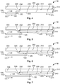
- Figures 4 to 7 illustrate a further possible design of the second plug connector 200, by means of which a contact force, which is substantially independent of the plug-in depth of the shielding sleeve 110 into the shielding bushing 210, can be achieved between the spring elements 230 of the shielding bushing 210 and the bead 140 of the shielding sleeve 110.
- a part of the shielding sleeve 110 of the first plug connector 100 and a spring element 230 of the shielding bushing 210 of the second plug connector 200 are depicted in each case.
- the second plug connector 200 has, moreover, an only partially depicted outer housing 300.
- the shielding bushing 210 is arranged in the outer housing 300.
- the outer housing 300 has an inner side 310 facing the shielding bushing 210.
- a projection 320 is arranged on the inner side 310 of the outer housing 300, but this can also be omitted.
- Figures 4 to 7 illustrate the procedure of the plugging-together of the first plug connector 100 and the second plug connector 200 in such a way that the plug-in depth of the shielding sleeve 110 of the first plug connector 100 into the shielding bushing 210 of the second plug connector 200 increases incrementally from the depiction in Fig. 4 to the depiction in Fig. 7 .
- the shielding sleeve 110 has not yet penetrated into the shielding bushing 210 at all.
- the arrangement shown in Fig. 7 can correspond to an end position and thus to a completely plugged-together state of the first plug connector 100 and the second plug connector 200.
- the second longitudinal ends 232 of the spring elements 230 of the shielding bushing 210 cannot be deflected further in the radial direction 212 of the shielding bushing 210.
- the spring elements 230 are deformed in accordance with a three-point deformation as the plug-in depth of the shielding sleeve 110 into the shielding bushing 210 increases further.
- the contact force exerted by the spring elements 230 of the shielding bushing 210 on the bead 140 of the shielding sleeve 110 remains substantially constant with the further increasing plug-in depth.
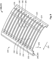
- Fig. 8 shows a diagrammatic depiction of a further possible design of the shielding bushing 210 of the second plug connector 200 of the plug connector system 10.
- Fig. 8 shows the shielding bushing 210 in an unwound state, in which the lateral surface of the cylindrical basic shape of the shielding bushing 210 is unwound to form a flat plate.
- the shielding bushing 210 is bent around an axis parallel to the longitudinal direction 211 to form a hollow-cylindrical shape.
- the spring elements 230 are clamped at their first longitudinal ends 231 and are free at their second longitudinal ends 232.
- the spring elements 230 in this case are separated from the other sections of the shielding bushing 210 by slots 260.
- a web 270 is arranged between adjacent spring elements 230 in each case.
- a further difference of the variant of the shielding bushing 210 shown in Fig. 8 from the variant of the shielding bushing 210 shown in Figures 1 and 3 is that the spring elements 230 in the variant of the shielding bushing 210 shown in Fig. 8 in the unstressed state are bent in such a way that middle sections of the spring elements 230 arranged between the first longitudinal ends 231 and the second longitudinal ends 232 protrude into the interior of the shielding bushing 210.
- the variant of the shielding bushing 210 shown in Fig. 8 moreover has an outwardly bent-over section 240 at its open end 220.
- This outwardly bent-over section 240 can, for example, form a retainer 250, which facilitates the insertion of the shielding sleeve 110 of the first plug connector 100 into the shielding bushing 210 of the second plug connector 200.
- the spring elements 230 of the variant of the shielding bushing 210 shown in Fig. 8 are bent in such a way that the second longitudinal ends 232 of the spring elements 230 bear against the bent-over section 240. As a result, it is achieved that the second longitudinal ends 232 of the spring elements 230 cannot be deflected further in the radial direction 212 of the shielding bushing 210 during the pushing of the shielding sleeve 110 of the first plug connector 100 into the shielding bushing 210. As a result, also in the case of the variant of the shielding bushing 210 shown in Fig.
- the spring elements 230 are deformed in accordance with a three-point deformation during the plugging of the shielding sleeve 110 into the shielding bushing 210. This can make it possible for the contact force exerted by the spring elements 230 of the shielding bushing 210 on the bead 140 of the shielding sleeve 110 to be largely independent of the plug-in depth of the shielding sleeve 110 in the shielding bushing 210.
- Fig. 9 shows a diagrammatic depiction of a further variant of the shielding bushing 210 of the second plug connector 200. Similarly to the depiction in Fig. 8 , for ease of depiction the shielding bushing 210 in Fig. 9 is shown in unwound form.
- the variant of the shielding bushing 210 shown in Fig. 9 differs from the variants of the shielding bushing 210 shown in Figures 1 , 3 and 8 in that the second longitudinal ends 232 of the spring elements 230 are not free, but rather are clamped.
- the second longitudinal ends 232 of the spring elements 230 are therefore, like the first longitudinal ends 231, connected to one another and to the other sections of the shielding bushing 210 in a materially uniform and cohesive manner.
- the spring elements 230 are separated from one another by slots 260 only between their first longitudinal ends 231 and their second longitudinal ends 232.
- the spring elements 230 in the unstressed state are bent in such a way that middle sections of the spring elements 230 arranged between the first longitudinal ends 231 and the second longitudinal ends 232 protrude into the space enclosed by the shielding bushing 210.
- no webs are formed between the spring elements 230.
- the variant without webs arranged between the spring elements 230, shown in Fig. 9 affords the advantage that a large contact region is formed between the spring elements 230 of the shielding bushing 210 and the bead 140 of the shielding sleeve 110.
- the variant of the shielding bushing 210 shown in Fig. 9 also has an outwardly bent-over section 240 at its open end 220. This can in turn serve to facilitate the insertion of the shielding sleeve 110 of the first plug connector 100 into the shielding bushing 210 of the second plug connector 200.
- Figures 10 and 11 show a schematic depiction of a further possible design of the shielding sleeve 110 of the first plug connector 100 of the plug connector system 10.
- Figure 10 shows a perspective view
- Figure 11 shows a side view.
- the variant of the shielding sleeve 110 shown in Figures 10 and 11 differs from the variant of the shielding sleeve 110 shown in Figures 1 and 2 in that the bead 140 in the variant of the shielding sleeve 110 shown in Figures 10 and 11 is not formed in a closed, circumferential manner. Instead, the bead 140 extends circumferentially only partially over the outer side 130 of the shielding sleeve 110.
- the bead 140 comprises two sections, which encompass an angle of 90° in each case and which are spaced apart from one another by gaps of 90° in each case.
- the bead 140 can, however, also be subdivided into a different number of sections, which run partially around the outer side 130 of the shielding sleeve 110 in a different way.
- the shielding sleeve 110 has a further bead 145 in the variant shown in Figures 10 and 11 .
- the further bead 145 likewise extends partially circumferentially around the outer side 130 of the shielding sleeve 110.
- the further bead 145 is orientated parallel to the bead 140 and perpendicularly to the longitudinal direction 111 of the shielding sleeve 110.
- the further bead 145 is offset from the bead 140 in the longitudinal direction 111 of the shielding sleeve 110 in such a way that the further bead 145 is spaced further apart from the longitudinal end 120 of the shielding sleeve 110 than the bead 140.
- the sections of the further bead 145 are formed to be complementary to the sections of the bead 140, in such a way that the individual sections of the further bead 145, in the circumferential direction of the shielding sleeve 110, cover precisely those angular ranges in which the bead 140 has gaps, and vice versa. Accordingly, in the example shown in Figures 10 and 11 , the further bead 145 likewise has two sections, which encompass an angle of 90° in each case and which are spaced apart from one another by gaps of 90° in each case.
- the further bead 145 with a different number of sections and with differently dimensioned sections, which run partially around the outer side 130 of the shielding sleeve 110 in a different way.
- the sections of the bead 140 and of the further bead 145 may overlap in the circumferential direction of the shielding sleeve 110, or for the outer side 130 of the shielding sleeve 110 to have angle sections in the circumferential direction, in which angle sections neither sections of the bead 140 nor of the further bead 145 are arranged.
- the shielding sleeve 110 of the first plug connector 100 of the plug connector system 10 is formed as depicted in Figures 10 and 11 , some of the spring elements 230 of the shielding bushing 210 of the second plug connector 200 come into contact with sections of the bead 140 during the connection of the first plug connector 100 to the second plug connector 200, but, in contrast, other spring elements 230 of the shielding bushing 210 of the second plug connector 200 come into contact with sections of the further bead 145 of the shielding sleeve 110 of the first plug connector 100.
- Figure 12 shows a schematic perspective depiction of a further possible design of the shielding sleeve 110 of the first plug connector 100 of the plug connector system 10.
- the bead 140 is formed in a closed, circumferential manner on the outer side 130 of the shielding sleeve 110.
- the bead 140 in this variant is not orientated perpendicularly to the longitudinal direction 111 of the shielding sleeve 110.
- the bead 140 is formed in such a way that, in the circumferential direction of the shielding sleeve 110, some sections of the bead 140 are arranged closer to the longitudinal end 120 of the shielding sleeve 110 than other sections of the bead 140.
- the shielding sleeve 110 of the first plug connector 100 of the plug connector system 10 is formed as in the example shown in Figure 12 , some of the spring elements 230 of the shielding bushing 210 of the second plug connector 200 are deflected by the bead 140 of the shielding sleeve 110 of the first plug connector 100 earlier than other spring elements 230 of the shielding bushing 210 during the plugging-together of the first plug connector 100 and the second plug connector 200.
- the configuration of the shielding sleeve 110 shown in Figure 12 it is achieved that the forces occurring during the plugging-together of the first plug connector 100 and the second plug connector 200 do not change significantly during the plugging-together.
- the described first plug connector can also be connected to plug connectors other than the described second plug connector to form a plug connector system.
- the described second plug connector can also be connected to plug connectors other than the described first plug connector to form a plug connector system.
Landscapes
- Details Of Connecting Devices For Male And Female Coupling (AREA)
Abstract
Description
- The present patent application relates to a plug connector system having a first plug connector and a second plug connector, and to a first plug connector and a second plug connector.
- Plug connector systems with a shielding housing are known in the prior art. Plug connectors of such plug connector systems have shields, which are electrically conductively connected to one another when the plug connectors are connected. In the case of a variant of such plug connector systems which is known from the prior art, one of the plug connectors has a shielding bushing with spring elements. The other plug connector has a shielding sleeve, which can be pushed into the shielding bushing of the plug connector counterpart. In this case, the shielding sleeve is electrically contacted by contact beads arranged at the tips of the spring elements of the shielding bushing. This known design, however, has the disadvantage that a part of the shielding sleeve protruding beyond the contact region forms a spur line arranged in the interior of the shield, the length of which spur line is dependent on the plug-in depth of the shielding sleeve. This can result in disadvantageous electrical properties, for example disadvantageous high-frequency properties.
- The problems addressed by the present invention consist in providing a plug connector system, a first plug connector and a second plug connector. These problems are solved by a plug connector system having the features of Claim 1, by a first plug connector according to Claim 13 and by a second plug connector according to Claim 14. Various developments are set forth in the dependent claims.
- A plug connector system comprises a first plug connector and a second plug connector. The first plug connector has a shielding sleeve. The second plug connector has a shielding bushing. The shielding sleeve has, on an outer side, an at least partially circumferential bead. The shielding bushing has a plurality of spring elements. The first plug connector can be connected to the second plug connector in such a way that the shielding sleeve is partially received in the shielding bushing and the bead is in contact with the spring elements.
- Advantageously in the case of this plug connector system, an electrically conductive connection between the shielding sleeve of the first plug connector and the shielding bushing of the second plug connector is produced by the at least partially circumferential bead on the outer side of the shielding sleeve arranged in the shielding bushing. As a result, in this plug connector system no spur line arranged inside the shield is formed, in particular no spur line whose dimensions depend on the plug-in depth of the shielding sleeve in the shielding bushing. Therefore, this plug connector system advantageously can have electrical properties which are simple to manage and independent of tolerances of the plug connectors.
- A further advantage consists in the fact that the contact regions of the spring elements are arranged on the inner sides of the spring elements and are protected as a result.
- A further advantage of this plug connector system arises from the fact that the spring elements are formed on the shielding bushing of the second plug connector. Since the shielding bushing of the second plug connector receives the shielding sleeve of the first plug connector, the shielding bushing, for its part, can be arranged in an outer housing of the second plug connector. In this case, the spring elements of the shielding bushing advantageously are protected from damage.
- In an embodiment, the spring elements can be deflected in a radial direction of the shielding bushing. As a result, advantageously the shielding sleeve of the first plug connector can be plugged into the shielding bushing of the second plug connector in a simple manner. The spring elements of the shielding bushing in this case are pressed against the at least partially circumferential bead on the outer side of the shielding sleeve and, as a result, produce an electrically conductive connection between the shielding bushing and the shielding sleeve.
- In an embodiment, the spring elements in the unstressed state are bent. Advantageously, as a result, the press-on force exerted by the spring elements of the shielding bushing on the bead of the shielding sleeve can be specified. A particular advantage is that the spring elements can be bent in such a way that the press-on force exerted by the spring elements on the bead remains substantially constant or within a desired value range during the plugging of the shielding sleeve into the shielding bushing.
- In an embodiment, the spring elements are formed as beams orientated in a longitudinal direction of the shielding bushing. In this case, each spring element has a first longitudinal end facing away from an open end of the shielding bushing and a second longitudinal end facing the open end of the shielding bushing. Advantageously, such a design of the spring elements is particularly highly suitable for producing an electrically conductive connection to the bead of the shielding sleeve by means of the spring elements.
- In an embodiment, each spring element is clamped at its first longitudinal end. This means that each spring element, at its first longitudinal end, is connected to the other sections of the shielding bushing in a materially uniform and cohesive manner. Advantageously, this results in a simple and robust design of the shielding bushing.
- In an embodiment, each spring element is clamped at its second longitudinal end. This means that each spring element, at its second longitudinal end, is connected to the other sections of the shielding bushing in a materially uniform and cohesive manner. Advantageously, this results in a simple and robust design of the shielding bushing.
- In an embodiment, the second longitudinal end of each spring element is free. This means that the spring elements, at their second longitudinal ends, are separated from the other sections of the shielding bushing. Then, the second longitudinal ends of the spring elements can be deflected at least partially against the other sections of the shielding bushing.
- In an embodiment, the shielding bushing has an outwardly bent-over section at its open end. In this case, the second longitudinal end, in the case of each spring element, bears against the bent-over section. The bent-over section of the shielding bushing advantageously can serve as an insertion retainer and can simplify the insertion of the shielding sleeve of the first plug connector into the shielding bushing of the second plug connector. The bearing of the second longitudinal ends of the spring elements of the shielding bushing against the bent-over section of the shielding bushing limits the deflectability of the second longitudinal ends of the spring elements and can advantageously thereby cause the force exerted by the spring elements of the shielding bushing on the at least partially circumferential bead of the shielding sleeve during the plugging of the shielding sleeve of the first plug connector into the shielding bushing of the second plug connector not to vary significantly with a change in the plug-in depth.
- In an embodiment, the second plug connector has an outer housing. In this case, the shielding bushing is arranged in the outer housing. The spring elements can be deflected, by pushing the shielding sleeve into the shielding bushing, in such a way that the second longitudinal end of each spring element comes to bear against the outer housing. Advantageously, the outer housing of the second plug connector can give protection for the spring elements of the second plug connector. The bearing of the second longitudinal ends of the spring elements against the outer housing can advantageously cause the press-on force exerted by the spring elements on the bead of the shielding sleeve during the plugging of the shielding sleeve into the shielding bushing not to change significantly with a change in the plug-in depth.
- In an embodiment, the outer housing has a projection on a side facing the shielding bushing. In this case, the second longitudinal end of each spring element comes to bear against the projection of the outer housing. Advantageously, in the case of this embodiment, it is possible to configure the course of the press-on force exerted by the spring elements of the shielding bushing on the bead of the shielding sleeve by way of a shaping of the projection.
- In an embodiment of the plug connector system, it is formed to transmit high-frequency signals. Advantageously, in the case of this plug connector, transmission of high-frequency signals is made possible by the shielding brought about by the shielding sleeve and the shielding bushing.
- In an embodiment of the plug connector system, it is formed to transmit high-frequency signals at a specified maximum frequency. In this case, at a base the bead has a spacing from a longitudinal end of the shielding sleeve. The spacing is less than a fifth of a wavelength of the maximum frequency conducted in the plug connector system, preferably less than a tenth of the wavelength. Advantageously, in the case of this plug connector system, no substantial spur line is formed in the unshielded region.
- The above-described properties, features and advantages of this invention are explained in greater detail hereinafter in conjunction with the figures. In the figures, in a schematic depiction in each case
- Fig. 1
- shows a sectional side view of a plug connector system having a first plug connector with a shielding sleeve and a second plug connector with a shielding bushing;
- Fig. 2
- shows a perspective depiction of the shielding sleeve of the first plug connector;
- Fig. 3
- shows a perspective depiction of the shielding bushing of the second plug connector;
- Figs. 4 to 7
- show sectional side views of a part of the plug connector system during the plugging-together of the first plug connector and the second plug connector;
- Fig. 8
- shows a perspective depiction of a further variant of the shielding bushing of the second plug connector;
- Fig. 9
- shows a perspective depiction of yet a further variant of the shielding bushing of the second plug connector;
- Fig. 10
- shows a perspective depiction of a further variant of the shielding sleeve of the first plug connector;
- Fig. 11
- shows a side view of this variant of the shielding sleeve; and
- Fig. 12
- shows a perspective depiction of yet a further variant of the shielding sleeve of the first plug connector.
-
Fig. 1 shows a schematic sectional side view of aplug connector system 10 having afirst plug connector 100 and asecond plug connector 200. For the sake of clarity, only parts of thefirst plug connector 100 and of thesecond plug connector 200 are depicted inFig. 1 . The depiction is limited substantially to a shielding housing of theplug connector system 10, which guarantees shielding. Theplug connector system 10 can be envisaged for transmitting high-frequency signals, for example. - The
first plug connector 100 of theplug connector system 10 has a shieldingsleeve 110.Fig. 1 shows only a part of the shieldingsleeve 110.Fig. 2 shows a perspective view of part of the shieldingsleeve 110 of thefirst plug connector 100. - The shielding
sleeve 110 has the basic shape of a hollow-cylindrical tube, which extends along alongitudinal direction 111 of the shieldingsleeve 110. The shieldingsleeve 110 can in this case have a circular cross-section, for example, as depicted inFig. 2 . Alternatively, the shieldingsleeve 110 can also have an elliptical cross-section, a rectangular cross-section or another cross-section. At alongitudinal end 120 of the shieldingsleeve 110, it is open. The shieldingsleeve 110 has an electrically conductive material, for example a metal. - An outer lateral surface of the
tubular shielding sleeve 110 forms anouter side 130 of the shieldingsleeve 110. On thisouter side 130, the shieldingsleeve 110 has acircumferential bead 140. Thebead 140 is formed as a thickened portion, which rises above the other sections of theouter side 130 of the shieldingsleeve 110. In this case, thebead 140 extends in an annular manner around theouter side 130 and is orientated perpendicularly to thelongitudinal direction 111 of the shieldingsleeve 110. Thebead 140 forms a contact region of the shieldingsleeve 110. Thebead 140 can enclose theouter side 130 in a closed, annular manner. Alternatively, thebead 140 can have one or a plurality of breaks in the circumferential direction, such that thebead 140 is formed only partially circumferentially. - It is expedient if the
bead 140 is arranged as close as possible to thelongitudinal end 120 of the shieldingsleeve 110. In the example shown inFigures 1 and2 , thebead 140 has awidth 160 measured in thelongitudinal direction 111 at abase 150 of thebead 140. In this case, thebase 150 of thebead 140 is defined as the region of thebead 140 at which it merges into the otherouter side 130 of the shieldingsleeve 110. Furthermore, thebead 140 in the example shown inFigures 1 and2 has a spacing 165 from thelongitudinal end 120 of the shieldingsleeve 110, measured in thelongitudinal direction 111 between the base 150 of thebead 140 and thelongitudinal end 120 of the shieldingsleeve 110. - It is expedient if the
spacing 165 is adapted to a maximum frequency of high-frequency signals transmitted by theplug connector system 10 in such a way that thespacing 165 is less than a fifth of a wavelength conducted at the maximum frequency in theplug connector system 10 or even less than a tenth of this wavelength. The maximum frequency of the high-frequency signals transmitted by theplug connector system 10 in this case can be the highest frequency which can be transmitted in a monomodal manner in theplug connector system 10. - The
second plug connector 200 of theplug connector system 10 has a shieldingbushing 210, which is not depicted completely inFig. 1 .Fig. 3 shows a perspective view of the shieldingbushing 210. - The shielding
bushing 210 has the basic form of a hollow-cylindrical tube, which extends along alongitudinal direction 211 of the shieldingbushing 210. A longitudinal end of the hollow-cylindrical tube forms anopen end 220 of the shieldingbushing 210. The shieldingbushing 210 has a cross-section matching the shieldingsleeve 110, therefore a circular cross-section, for example, as depicted inFig. 3 . - In
Fig. 1 , it can be seen that the shieldingbushing 210 of thesecond plug connector 200 has a somewhat larger diameter than the shieldingsleeve 110 of thefirst plug connector 100. As a result, the shieldingsleeve 110 of thefirst plug connector 100 can be received at least partially in the shieldingbushing 210 of thesecond plug connector 200. If thefirst plug connector 100 and thesecond plug connector 200 of theplug connector system 10 are connected to one another by thefirst plug connector 100 and thesecond plug connector 200 being plugged together, the shieldingsleeve 110 of thefirst plug connector 100 is partially plugged into the shieldingbushing 210 of thesecond plug connector 200. In this case, thelongitudinal end 120 of the shieldingsleeve 110 penetrates into theopen end 220 of the shieldingbushing 210. - The shielding
bushing 210 of thesecond plug connector 200 has a plurality ofspring elements 230. Thespring elements 230 are arranged at theopen end 220 of the shieldingbushing 210. Thespring elements 230 are formed as beams, which are orientated along thelongitudinal direction 211 of the shieldingbushing 210. In this case, eachspring element 230 of the shieldingbushing 210 has a firstlongitudinal end 231 and a secondlongitudinal end 232. The first longitudinal ends 231 of thespring elements 230 face away from theopen end 220 of the shieldingbushing 210. The second longitudinal ends 232 of thespring elements 230 face theopen end 220 of the shieldingbushing 210. At their first longitudinal ends 231, thespring elements 230 are connected to the other sections of the shieldingbushing 210. As a result, eachspring element 230 is clamped at its firstlongitudinal end 231. The second longitudinal ends 232 of thespring elements 230 are not connected to one another or to other sections of the shieldingbushing 210, and are free as a result. - If the shielding
sleeve 110 of thefirst plug connector 100 is pushed into the shieldingbushing 210 of thesecond plug connector 200 during the connection of thefirst plug connector 100 to thesecond plug connector 200, thebead 140 arranged on theouter side 130 of the shieldingsleeve 110 comes into contact with aninner side 225 of the shieldingbushing 210 in the region of thespring elements 230 of the shieldingbushing 210. This is depicted inFig. 1 . As a result, an electrically conductive connection is produced between the shieldingsleeve 110 of thefirst plug connector 100 and the shieldingbushing 210 of thesecond plug connector 200. - The
spring elements 230 of the shieldingbushing 210 of thesecond plug connector 200 can be deflected in aradial direction 212 of the shieldingbushing 210. The outer diameter of thebead 140 of the shieldingsleeve 110 of thefirst plug connector 100 and the inner diameter of the shieldingbushing 210 of thesecond plug connector 200 are adapted to one another in such a way that thespring elements 230 are deflected resiliently in theradial direction 212 of the shieldingbushing 210 during the plugging of the shieldingsleeve 110 into the shieldingbushing 210. As a result, reliable contact between thespring elements 230 of the shieldingbushing 210 and thebead 140 of the shieldingsleeve 110 can be guaranteed. - It is expedient if the spring force exerted by the
spring elements 230 of the shieldingbushing 210 on thebead 140 of the shieldingsleeve 110 does not change significantly with the plug-in depth of the shieldingsleeve 110 into the shieldingbushing 210. In this case, the force exerted by thespring elements 230 of the shieldingbushing 210 on thebead 140 of the shieldingsleeve 110 during the plugging into the shieldingbushing 210 remains substantially the same at all positions of the shieldingsleeve 110 in the shieldingbushing 210. The spring force exerted by thespring elements 230 of the shieldingbushing 210 on thebead 140 of the shieldingsleeve 110 can also be referred to as the contact force. - A contact force which is substantially independent of the plug-in depth can, for example, be achieved in that the
spring elements 230 of the shieldingbushing 210 are formed with a shape which deviates from a simple beam shape. For example, thespring elements 230 can be profiled on theinner side 225 of the shieldingbushing 210 in such a way that the deflection of thespring elements 230 in theradial direction 212 during the plugging of the shieldingsleeve 110 into the shieldingbushing 210 remains substantially constant for all plug-in depths. Another possibility consists in forming thespring elements 230 with a thickness or width which is variable along its longitudinal direction, in order to achieve a return force of thespring elements 230 which is substantially independent of the plug-in depth. -
Figures 4 to 7 illustrate a further possible design of thesecond plug connector 200, by means of which a contact force, which is substantially independent of the plug-in depth of the shieldingsleeve 110 into the shieldingbushing 210, can be achieved between thespring elements 230 of the shieldingbushing 210 and thebead 140 of the shieldingsleeve 110. A part of the shieldingsleeve 110 of thefirst plug connector 100 and aspring element 230 of the shieldingbushing 210 of thesecond plug connector 200 are depicted in each case. In this variant, thesecond plug connector 200 has, moreover, an only partially depictedouter housing 300. The shieldingbushing 210 is arranged in theouter housing 300. Theouter housing 300 has aninner side 310 facing the shieldingbushing 210. Aprojection 320 is arranged on theinner side 310 of theouter housing 300, but this can also be omitted. -
Figures 4 to 7 illustrate the procedure of the plugging-together of thefirst plug connector 100 and thesecond plug connector 200 in such a way that the plug-in depth of the shieldingsleeve 110 of thefirst plug connector 100 into the shieldingbushing 210 of thesecond plug connector 200 increases incrementally from the depiction inFig. 4 to the depiction inFig. 7 . In the depiction inFig. 4 , the shieldingsleeve 110 has not yet penetrated into the shieldingbushing 210 at all. The arrangement shown inFig. 7 can correspond to an end position and thus to a completely plugged-together state of thefirst plug connector 100 and thesecond plug connector 200. - In
Figures 5, 6 and 7 , it can be seen that thebead 140 of the shieldingsleeve 110 of thefirst plug connector 100 deflects thespring elements 230 of the shieldingbushing 210 of thesecond plug connector 200 in theradial direction 212 of thesecond plug connector 200. In this case, the second longitudinal ends 232 of thespring elements 230 come to bear against theprojection 320 arranged on theinner side 310 of theouter housing 300. If theprojection 320 were not present, the second longitudinal ends 232 of thespring elements 230 would come to bear directly against theinner side 310 of theouter housing 300. - As a result of the bearing of the second longitudinal ends 232 of the
spring elements 230 of the shieldingbushing 210 against theinner side 310 of theouter housing 300, it is achieved that the second longitudinal ends 232 of thespring elements 230 cannot be deflected further in theradial direction 212 of the shieldingbushing 210. As a result, thespring elements 230 are deformed in accordance with a three-point deformation as the plug-in depth of the shieldingsleeve 110 into the shieldingbushing 210 increases further. As a result, it is achieved that the contact force exerted by thespring elements 230 of the shieldingbushing 210 on thebead 140 of the shieldingsleeve 110 remains substantially constant with the further increasing plug-in depth. -
Fig. 8 shows a diagrammatic depiction of a further possible design of the shieldingbushing 210 of thesecond plug connector 200 of theplug connector system 10. For ease of depiction,Fig. 8 shows the shieldingbushing 210 in an unwound state, in which the lateral surface of the cylindrical basic shape of the shieldingbushing 210 is unwound to form a flat plate. In reality, the shieldingbushing 210 is bent around an axis parallel to thelongitudinal direction 211 to form a hollow-cylindrical shape. - Also in the variant of the shielding
bushing 210 shown inFig. 8 , thespring elements 230 are clamped at their first longitudinal ends 231 and are free at their second longitudinal ends 232. Thespring elements 230 in this case are separated from the other sections of the shieldingbushing 210 byslots 260. In the variant of the shieldingbushing 210 shown inFig. 8 , in contrast to the variant of the shieldingbushing 210 shown inFigures 1 and3 , aweb 270 is arranged betweenadjacent spring elements 230 in each case. As a result, the variant of the shieldingbushing 210 shown inFig. 8 can have a great torsional rigidity. - A further difference of the variant of the shielding
bushing 210 shown inFig. 8 from the variant of the shieldingbushing 210 shown inFigures 1 and3 is that thespring elements 230 in the variant of the shieldingbushing 210 shown inFig. 8 in the unstressed state are bent in such a way that middle sections of thespring elements 230 arranged between the first longitudinal ends 231 and the second longitudinal ends 232 protrude into the interior of the shieldingbushing 210. - The variant of the shielding
bushing 210 shown inFig. 8 moreover has an outwardly bent-over section 240 at itsopen end 220. This outwardly bent-over section 240 can, for example, form a retainer 250, which facilitates the insertion of the shieldingsleeve 110 of thefirst plug connector 100 into the shieldingbushing 210 of thesecond plug connector 200. - The
spring elements 230 of the variant of the shieldingbushing 210 shown inFig. 8 are bent in such a way that the second longitudinal ends 232 of thespring elements 230 bear against the bent-over section 240. As a result, it is achieved that the second longitudinal ends 232 of thespring elements 230 cannot be deflected further in theradial direction 212 of the shieldingbushing 210 during the pushing of the shieldingsleeve 110 of thefirst plug connector 100 into the shieldingbushing 210. As a result, also in the case of the variant of the shieldingbushing 210 shown inFig. 8 , it is achieved that thespring elements 230 are deformed in accordance with a three-point deformation during the plugging of the shieldingsleeve 110 into the shieldingbushing 210. This can make it possible for the contact force exerted by thespring elements 230 of the shieldingbushing 210 on thebead 140 of the shieldingsleeve 110 to be largely independent of the plug-in depth of the shieldingsleeve 110 in the shieldingbushing 210. -
Fig. 9 shows a diagrammatic depiction of a further variant of the shieldingbushing 210 of thesecond plug connector 200. Similarly to the depiction inFig. 8 , for ease of depiction the shieldingbushing 210 inFig. 9 is shown in unwound form. - The variant of the shielding
bushing 210 shown inFig. 9 differs from the variants of the shieldingbushing 210 shown inFigures 1 ,3 and8 in that the second longitudinal ends 232 of thespring elements 230 are not free, but rather are clamped. The second longitudinal ends 232 of thespring elements 230 are therefore, like the first longitudinal ends 231, connected to one another and to the other sections of the shieldingbushing 210 in a materially uniform and cohesive manner. Thespring elements 230 are separated from one another byslots 260 only between their first longitudinal ends 231 and their second longitudinal ends 232. - In the case of the variant of the shielding
bushing 210 shown inFig. 9 , thespring elements 230 in the unstressed state are bent in such a way that middle sections of thespring elements 230 arranged between the first longitudinal ends 231 and the second longitudinal ends 232 protrude into the space enclosed by the shieldingbushing 210. In the case of the variant of the shieldingbushing 210 shown inFig. 9 , no webs are formed between thespring elements 230. However, it is possible to form the variant of the shieldingbushing 210 shown inFig. 9 with webs which are arranged between thespring elements 230 and which are not bent. The variant without webs arranged between thespring elements 230, shown inFig. 9 , affords the advantage that a large contact region is formed between thespring elements 230 of the shieldingbushing 210 and thebead 140 of the shieldingsleeve 110. - The variant of the shielding
bushing 210 shown inFig. 9 also has an outwardly bent-over section 240 at itsopen end 220. This can in turn serve to facilitate the insertion of the shieldingsleeve 110 of thefirst plug connector 100 into the shieldingbushing 210 of thesecond plug connector 200. -
Figures 10 and 11 show a schematic depiction of a further possible design of the shieldingsleeve 110 of thefirst plug connector 100 of theplug connector system 10. In this case,Figure 10 shows a perspective view, whileFigure 11 shows a side view. - The variant of the shielding
sleeve 110 shown inFigures 10 and 11 differs from the variant of the shieldingsleeve 110 shown inFigures 1 and2 in that thebead 140 in the variant of the shieldingsleeve 110 shown inFigures 10 and 11 is not formed in a closed, circumferential manner. Instead, thebead 140 extends circumferentially only partially over theouter side 130 of the shieldingsleeve 110. In the example shown inFigures 10 and 11 , thebead 140 comprises two sections, which encompass an angle of 90° in each case and which are spaced apart from one another by gaps of 90° in each case. Thebead 140 can, however, also be subdivided into a different number of sections, which run partially around theouter side 130 of the shieldingsleeve 110 in a different way. - In addition to the
bead 140, the shieldingsleeve 110 has afurther bead 145 in the variant shown inFigures 10 and 11 . Thefurther bead 145 likewise extends partially circumferentially around theouter side 130 of the shieldingsleeve 110. Thefurther bead 145 is orientated parallel to thebead 140 and perpendicularly to thelongitudinal direction 111 of the shieldingsleeve 110. In this case, thefurther bead 145 is offset from thebead 140 in thelongitudinal direction 111 of the shieldingsleeve 110 in such a way that thefurther bead 145 is spaced further apart from thelongitudinal end 120 of the shieldingsleeve 110 than thebead 140. - In the depicted example, the sections of the
further bead 145 are formed to be complementary to the sections of thebead 140, in such a way that the individual sections of thefurther bead 145, in the circumferential direction of the shieldingsleeve 110, cover precisely those angular ranges in which thebead 140 has gaps, and vice versa. Accordingly, in the example shown inFigures 10 and 11 , thefurther bead 145 likewise has two sections, which encompass an angle of 90° in each case and which are spaced apart from one another by gaps of 90° in each case. However, it is also possible to form thefurther bead 145 with a different number of sections and with differently dimensioned sections, which run partially around theouter side 130 of the shieldingsleeve 110 in a different way. In particular, it is also possible for the sections of thebead 140 and of thefurther bead 145 to overlap in the circumferential direction of the shieldingsleeve 110, or for theouter side 130 of the shieldingsleeve 110 to have angle sections in the circumferential direction, in which angle sections neither sections of thebead 140 nor of thefurther bead 145 are arranged. - If the shielding
sleeve 110 of thefirst plug connector 100 of theplug connector system 10 is formed as depicted inFigures 10 and 11 , some of thespring elements 230 of the shieldingbushing 210 of thesecond plug connector 200 come into contact with sections of thebead 140 during the connection of thefirst plug connector 100 to thesecond plug connector 200, but, in contrast,other spring elements 230 of the shieldingbushing 210 of thesecond plug connector 200 come into contact with sections of thefurther bead 145 of the shieldingsleeve 110 of thefirst plug connector 100. During the plugging-together of thefirst plug connector 100 and thesecond plug connector 200, thespring elements 230 coming into contact with sections of thebead 140 are deflected earlier than thespring elements 230 coming into contact with sections of thefurther bead 145. As a result, it is achieved that the forces acting during the plugging-together of thefirst plug connector 100 and thesecond plug connector 200 do not depend significantly on the plug-in depth. -
Figure 12 shows a schematic perspective depiction of a further possible design of the shieldingsleeve 110 of thefirst plug connector 100 of theplug connector system 10. - In the case of the variant of the shielding
sleeve 110 shown inFigure 12 , thebead 140 is formed in a closed, circumferential manner on theouter side 130 of the shieldingsleeve 110. However, thebead 140 in this variant is not orientated perpendicularly to thelongitudinal direction 111 of the shieldingsleeve 110. Instead, thebead 140 is formed in such a way that, in the circumferential direction of the shieldingsleeve 110, some sections of thebead 140 are arranged closer to thelongitudinal end 120 of the shieldingsleeve 110 than other sections of thebead 140. - If the shielding
sleeve 110 of thefirst plug connector 100 of theplug connector system 10 is formed as in the example shown inFigure 12 , some of thespring elements 230 of the shieldingbushing 210 of thesecond plug connector 200 are deflected by thebead 140 of the shieldingsleeve 110 of thefirst plug connector 100 earlier thanother spring elements 230 of the shieldingbushing 210 during the plugging-together of thefirst plug connector 100 and thesecond plug connector 200. As a result, also by way of the configuration of the shieldingsleeve 110 shown inFigure 12 , it is achieved that the forces occurring during the plugging-together of thefirst plug connector 100 and thesecond plug connector 200 do not change significantly during the plugging-together. - The described first plug connector can also be connected to plug connectors other than the described second plug connector to form a plug connector system.
- The described second plug connector can also be connected to plug connectors other than the described first plug connector to form a plug connector system.
-
- 10
- plug connector system
- 100
- first plug connector
- 110
- shielding sleeve
- 111
- longitudinal direction of the shielding sleeve
- 120
- longitudinal end of the shielding sleeve
- 130
- outer side
- 140
- bead
- 145
- further bead
- 150
- base
- 160
- width
- 165
- spacing
- 200
- second plug connector
- 210
- shielding bushing
- 211
- longitudinal direction of the shielding bushing
- 212
- radial direction of the shielding bushing
- 220
- open end of the shielding bushing
- 225
- inner side
- 230
- spring element
- 231
- first longitudinal end
- 232
- second longitudinal end
- 240
- bent-over section
- 250
- retainer
- 260
- slot
- 270
- web
- 300
- outer housing
- 310
- inner side
- 320
- projection
Claims (14)
- A plug connector system (10)
having a first plug connector (100) and a second plug connector (200),
wherein the first plug connector (100) has a shielding sleeve (110),
wherein the second plug connector (200) has a shielding bushing (210),
wherein the shielding sleeve (110) has, on an outer side (130), an at least partially circumferential bead (140), wherein the shielding bushing (210) has a plurality of spring elements (230),
wherein the first plug connector (100) can be connected to the second plug connector (200) in such a way that the shielding sleeve (110) is partially received in the shielding bushing (210) and the bead (140) is in contact with the spring elements (230). - The plug connector system (10) according to Claim 1, wherein the spring elements (230) can be deflected in a radial direction (212) of the shielding bushing (210).
- The plug connector system (10) according to either one of the preceding claims,
wherein the spring elements (230) in the unstressed state are bent. - The plug connector system (10) according to any one of the preceding claims,
wherein the spring elements (230) are formed as beams orientated in a longitudinal direction (211) of the shielding bushing (210),
wherein each spring element (230) has a first longitudinal end (231) facing away from an open end (220) of the shielding bushing (210) and a second longitudinal end (232) facing the open end (220) of the shielding bushing (210). - The plug connector system (10) according to Claim 4,
wherein each spring element (230) is clamped at its first longitudinal end (231). - The plug connector system (10) according to either one of Claims 4 and 5,
wherein each spring element (230) is clamped at its second longitudinal end (232). - The plug connector system (10) according to either one of Claims 4 and 5,
wherein the second longitudinal end (232) of each spring element (230) is free. - The plug connector system (10) according to Claim 7,
wherein the shielding bushing (210) has an outwardly bent-over section (240) at its open end (220),
wherein the second longitudinal end (232), in the case of each spring element (230), bears against the bent-over section (240). - The plug connector system (10) according to Claims 2 and 7,
wherein the second plug connector (200) has an outer housing (300),
wherein the shielding bushing (210) is arranged in the outer housing (300),
wherein the spring elements (230) can be deflected, by pushing the shielding sleeve (110) into the shielding bushing (210), in such a way that the second longitudinal end (232) of each spring element (230) comes to bear against the outer housing (300). - The plug connector system (10) according to Claim 9,
wherein the outer housing (300) has a projection (320) on a side (310) facing the shielding bushing (210),
wherein the second longitudinal end (232) of each spring element (230) comes to bear against the projection (320) of the outer housing (300). - The plug connector system (10) according to any one of the preceding claims,
wherein the plug connector system (10) is formed to transmit high-frequency signals. - The plug connector system (10) according to Claim 11,
wherein the plug connector system (10) is formed to transmit high-frequency signals at a specified maximum frequency,
wherein at a base (150) the bead (140) has a spacing (165) from a longitudinal end (120) of the shielding sleeve (110),
wherein the spacing (165) is less than a fifth of a wavelength of the maximum frequency conducted in the plug connector system (10), preferably less than a tenth of the wavelength. - A first plug connector (100),
wherein the first plug connector (100) has a shielding sleeve (110),
wherein the shielding sleeve (110) has, on an outer side (130), an at least partially circumferential bead (140), wherein the first plug connector (100) can be connected to a second plug connector (200) in such a way that the shielding sleeve (110) is partially received in a shielding bushing (210) of the second plug connector (200) and the bead (140) is in contact with the spring elements (230). - A second plug connector (200),
wherein the second plug connector (200) has a shielding bushing (210),
wherein the shielding bushing (210) has a plurality of spring elements (230),
wherein the second plug connector (200) can be connected to a first plug connector (100) in such a way that the shielding bushing (210) partially receives a shielding sleeve (110) of the first plug connector (100) and the spring elements (230) are in contact with a bead (140) of the shielding sleeve (110).
Applications Claiming Priority (1)
| Application Number | Priority Date | Filing Date | Title |
|---|---|---|---|
| DE102019114646.1A DE102019114646A1 (en) | 2019-05-31 | 2019-05-31 | Connector system |
Publications (1)
| Publication Number | Publication Date |
|---|---|
| EP3745543A1 true EP3745543A1 (en) | 2020-12-02 |
Family
ID=70918285
Family Applications (1)
| Application Number | Title | Priority Date | Filing Date |
|---|---|---|---|
| EP20177029.4A Pending EP3745543A1 (en) | 2019-05-31 | 2020-05-28 | Plug connector system |
Country Status (5)
| Country | Link |
|---|---|
| US (1) | US11183797B2 (en) |
| EP (1) | EP3745543A1 (en) |
| JP (1) | JP7566491B2 (en) |
| CN (1) | CN112018570B (en) |
| DE (1) | DE102019114646A1 (en) |
Families Citing this family (1)
| Publication number | Priority date | Publication date | Assignee | Title |
|---|---|---|---|---|
| DE102023110353B3 (en) | 2023-04-24 | 2024-09-26 | Amphenol-Tuchel Electronics Gesellschaft mit beschränkter Haftung | Connectors for electrically conductive contact |
Citations (4)
| Publication number | Priority date | Publication date | Assignee | Title |
|---|---|---|---|---|
| EP1094565A1 (en) * | 1999-10-22 | 2001-04-25 | Huber+Suhner Ag | Coaxial connector |
| JP2002075543A (en) * | 2000-08-23 | 2002-03-15 | Auto Network Gijutsu Kenkyusho:Kk | Shield connector |
| US20100304598A1 (en) * | 2009-06-01 | 2010-12-02 | Thomas Kari | Coaxial connector with coupling spring |
| US20180248290A1 (en) * | 2015-09-29 | 2018-08-30 | Rosenberger Hochfrequenztechnik Gmbh & Co. Kg | Contact lamella part and plug connector with contact lamella part |
Family Cites Families (27)
| Publication number | Priority date | Publication date | Assignee | Title |
|---|---|---|---|---|
| US2502302A (en) * | 1945-04-09 | 1950-03-28 | James H Cannon | Connector |
| US5147221A (en) * | 1989-08-13 | 1992-09-15 | The Starling Manufacturing Company | Combination socket and wingless cable-end radio pin connector |
| JPH04133373U (en) * | 1991-05-31 | 1992-12-11 | 第一電子工業株式会社 | electrical connectors |
| FR2715004B1 (en) * | 1994-01-13 | 1996-03-01 | Radiall Sa | Microminiature coaxial connector with snap lock. |
| JP2914266B2 (en) * | 1996-01-24 | 1999-06-28 | 日本電気株式会社 | Coaxial connector connection adapter and coaxial connector connection structure |
| JPH10189163A (en) * | 1996-12-25 | 1998-07-21 | Uro Denshi Kogyo Kk | Interface unit for coaxial cable |
| US6554646B1 (en) * | 1998-12-14 | 2003-04-29 | Berg Electronics Group, Inc. | Electrical connector assembly |
| GB2324204A (en) * | 1997-04-01 | 1998-10-14 | Itt Mfg Enterprises Inc | Connector locking mechanism |
| JP3498890B2 (en) * | 1998-01-22 | 2004-02-23 | 矢崎総業株式会社 | Connector and connector assembling method |
| DE20007001U1 (en) * | 2000-04-15 | 2000-07-27 | Anton Hummel Verwaltungs Gmbh, 79183 Waldkirch | Plug with a sleeve |
| CN100448116C (en) * | 2002-05-08 | 2008-12-31 | 优特私人有限公司 | Device for distributing electric power and/or communication signals |
| US6739885B2 (en) * | 2002-05-21 | 2004-05-25 | Tyco Electronics Corporation | Filtered and shielded electrical connector |
| TW545726U (en) * | 2002-09-25 | 2003-08-01 | Hon Hai Prec Ind Co Ltd | Electrical connector |
| TW549667U (en) * | 2002-12-04 | 2003-08-21 | Hon Hai Prec Ind Co Ltd | Radio frequency connector assembly |
| DE102004002402B3 (en) | 2004-01-16 | 2005-11-03 | Tyco Electronics Amp Gmbh | High-current connection device and associated contacting element |
| DE102008018403A1 (en) * | 2008-04-10 | 2009-10-15 | Weidmüller Interface GmbH & Co. KG | Connector with a shielded cable connected to it |
| US7553185B1 (en) * | 2008-05-07 | 2009-06-30 | Jinliang Qu | Dual-extrusion airtight RF coaxial connector with self-locking by snap-fastening |
| US7481673B1 (en) * | 2008-05-07 | 2009-01-27 | Jinliang Qu | Airtight RF coaxial connector with self-locking by snap-fastening |
| US7611378B1 (en) * | 2008-09-26 | 2009-11-03 | Tyco Electronics Corporation | Rotationally adjustable connector assembly |
| JP5270480B2 (en) | 2008-11-05 | 2013-08-21 | 富士通コンポーネント株式会社 | connector |
| TWM357080U (en) * | 2008-12-24 | 2009-05-11 | Advanced Connectek Inc | Socket connector |
| GB2477987B (en) * | 2010-02-22 | 2014-01-08 | Itt Mfg Entpr Llc | Electrical connector |
| DE202012008961U1 (en) | 2012-09-17 | 2012-10-12 | Rosenberger Hochfrequenztechnik Gmbh & Co. Kg | contact element |
| US9425548B2 (en) * | 2012-11-09 | 2016-08-23 | Commscope Technologies Llc | Resilient coaxial connector interface and method of manufacture |
| US9106025B2 (en) * | 2013-07-09 | 2015-08-11 | Coninvers Gmbh | Shielded circular plug connector unit with symmetrically arranged plug contacts |
| CN108701928A (en) | 2016-02-26 | 2018-10-23 | 罗森伯格高频技术有限及两合公司 | Contact sleeves for electrical plug connectors |
| KR20180113539A (en) | 2016-02-26 | 2018-10-16 | 로젠버거 호흐프리쿠벤츠테흐닉 게엠베하 운트 코. 카게 | Electrical plug connector |
-
2019
- 2019-05-31 DE DE102019114646.1A patent/DE102019114646A1/en active Pending
-
2020
- 2020-05-26 JP JP2020091003A patent/JP7566491B2/en active Active
- 2020-05-28 EP EP20177029.4A patent/EP3745543A1/en active Pending
- 2020-05-28 US US16/886,124 patent/US11183797B2/en active Active
- 2020-05-29 CN CN202010472971.1A patent/CN112018570B/en active Active
Patent Citations (4)
| Publication number | Priority date | Publication date | Assignee | Title |
|---|---|---|---|---|
| EP1094565A1 (en) * | 1999-10-22 | 2001-04-25 | Huber+Suhner Ag | Coaxial connector |
| JP2002075543A (en) * | 2000-08-23 | 2002-03-15 | Auto Network Gijutsu Kenkyusho:Kk | Shield connector |
| US20100304598A1 (en) * | 2009-06-01 | 2010-12-02 | Thomas Kari | Coaxial connector with coupling spring |
| US20180248290A1 (en) * | 2015-09-29 | 2018-08-30 | Rosenberger Hochfrequenztechnik Gmbh & Co. Kg | Contact lamella part and plug connector with contact lamella part |
Also Published As
| Publication number | Publication date |
|---|---|
| JP7566491B2 (en) | 2024-10-15 |
| US20200381870A1 (en) | 2020-12-03 |
| JP2020198302A (en) | 2020-12-10 |
| DE102019114646A1 (en) | 2020-12-03 |
| CN112018570A (en) | 2020-12-01 |
| US11183797B2 (en) | 2021-11-23 |
| CN112018570B (en) | 2024-12-06 |
Similar Documents
| Publication | Publication Date | Title |
|---|---|---|
| KR102094628B1 (en) | Contact sleeve for electrical plug connector | |
| US10958017B2 (en) | Contact element for a connector | |
| US10553977B2 (en) | Electrical plug connector | |
| EP2615699A1 (en) | RF Connector | |
| CN102957052A (en) | Shielded connector | |
| JP2018534733A (en) | Plug socket connector | |
| JP7239714B2 (en) | Automotive Ethernet plug-in connector and plug-in connector device with Ethernet plug-in connector | |
| US10468837B2 (en) | Coaxial connector assembly | |
| US6752667B2 (en) | Electrical connection element and a housing for an electrical connection element | |
| EP3218965A1 (en) | Connector assembly | |
| WO2020203591A1 (en) | Multipolar connector set | |
| US4168880A (en) | Electrical socket | |
| US11183797B2 (en) | Plug connector system | |
| KR102757032B1 (en) | Coaxial board-to-board connector | |
| CN111213292A (en) | Printed circuit board plug connector with shielding element | |
| EP3787130A1 (en) | Connector shielding with a guiding protrusion | |
| KR102201515B1 (en) | Coaxial connector | |
| KR102675450B1 (en) | Contact device, in particular a coaxial contact device | |
| US20240305045A1 (en) | Electrical Plug Connector and Electrical Plug Connection | |
| EP2779318A1 (en) | Method for assembling an electrical connector and electrical connector | |
| US10326226B2 (en) | Contact with a first cylindrical section, a second cylindrical section, and a transition section and a connector using the same | |
| WO2023149116A1 (en) | Connector | |
| JP2019102251A (en) | Electrical connector |
Legal Events
| Date | Code | Title | Description |
|---|---|---|---|
| PUAI | Public reference made under article 153(3) epc to a published international application that has entered the european phase |
Free format text: ORIGINAL CODE: 0009012 |
|
| STAA | Information on the status of an ep patent application or granted ep patent |
Free format text: STATUS: THE APPLICATION HAS BEEN PUBLISHED |
|
| AK | Designated contracting states |
Kind code of ref document: A1 Designated state(s): AL AT BE BG CH CY CZ DE DK EE ES FI FR GB GR HR HU IE IS IT LI LT LU LV MC MK MT NL NO PL PT RO RS SE SI SK SM TR |
|
| AX | Request for extension of the european patent |
Extension state: BA ME |
|
| STAA | Information on the status of an ep patent application or granted ep patent |
Free format text: STATUS: REQUEST FOR EXAMINATION WAS MADE |
|
| 17P | Request for examination filed |
Effective date: 20201202 |
|
| RBV | Designated contracting states (corrected) |
Designated state(s): AL AT BE BG CH CY CZ DE DK EE ES FI FR GB GR HR HU IE IS IT LI LT LU LV MC MK MT NL NO PL PT RO RS SE SI SK SM TR |
|
| STAA | Information on the status of an ep patent application or granted ep patent |
Free format text: STATUS: EXAMINATION IS IN PROGRESS |
|
| 17Q | First examination report despatched |
Effective date: 20210928 |
|
| 17Q | First examination report despatched |
Effective date: 20230605 |