EP3745489A1 - Pole-held power supply - Google Patents
Pole-held power supply Download PDFInfo
- Publication number
- EP3745489A1 EP3745489A1 EP18904530.5A EP18904530A EP3745489A1 EP 3745489 A1 EP3745489 A1 EP 3745489A1 EP 18904530 A EP18904530 A EP 18904530A EP 3745489 A1 EP3745489 A1 EP 3745489A1
- Authority
- EP
- European Patent Office
- Prior art keywords
- pole
- power supply
- mounted power
- electrochemical cells
- support pole
- Prior art date
- Legal status (The legal status is an assumption and is not a legal conclusion. Google has not performed a legal analysis and makes no representation as to the accuracy of the status listed.)
- Withdrawn
Links
- 230000005484 gravity Effects 0.000 claims abstract description 36
- 229910000831 Steel Inorganic materials 0.000 claims description 24
- 239000010959 steel Substances 0.000 claims description 24
- 238000010438 heat treatment Methods 0.000 claims description 7
- 230000017525 heat dissipation Effects 0.000 abstract description 11
- 238000013021 overheating Methods 0.000 abstract description 8
- 239000000470 constituent Substances 0.000 description 10
- 238000010586 diagram Methods 0.000 description 9
- 230000002093 peripheral effect Effects 0.000 description 8
- RYGMFSIKBFXOCR-UHFFFAOYSA-N Copper Chemical compound [Cu] RYGMFSIKBFXOCR-UHFFFAOYSA-N 0.000 description 6
- 229910052802 copper Inorganic materials 0.000 description 6
- 239000010949 copper Substances 0.000 description 6
- 230000003014 reinforcing effect Effects 0.000 description 5
- 238000005516 engineering process Methods 0.000 description 2
- 230000007423 decrease Effects 0.000 description 1
- 238000007599 discharging Methods 0.000 description 1
- 230000000694 effects Effects 0.000 description 1
- 238000000034 method Methods 0.000 description 1
- 238000012986 modification Methods 0.000 description 1
- 230000004048 modification Effects 0.000 description 1
- 230000005855 radiation Effects 0.000 description 1
- 230000000630 rising effect Effects 0.000 description 1
Images



Classifications
-
- F—MECHANICAL ENGINEERING; LIGHTING; HEATING; WEAPONS; BLASTING
- F16—ENGINEERING ELEMENTS AND UNITS; GENERAL MEASURES FOR PRODUCING AND MAINTAINING EFFECTIVE FUNCTIONING OF MACHINES OR INSTALLATIONS; THERMAL INSULATION IN GENERAL
- F16M—FRAMES, CASINGS OR BEDS OF ENGINES, MACHINES OR APPARATUS, NOT SPECIFIC TO ENGINES, MACHINES OR APPARATUS PROVIDED FOR ELSEWHERE; STANDS; SUPPORTS
- F16M13/00—Other supports for positioning apparatus or articles; Means for steadying hand-held apparatus or articles
- F16M13/02—Other supports for positioning apparatus or articles; Means for steadying hand-held apparatus or articles for supporting on, or attaching to, an object, e.g. tree, gate, window-frame, cycle
-
- H—ELECTRICITY
- H01—ELECTRIC ELEMENTS
- H01M—PROCESSES OR MEANS, e.g. BATTERIES, FOR THE DIRECT CONVERSION OF CHEMICAL ENERGY INTO ELECTRICAL ENERGY
- H01M10/00—Secondary cells; Manufacture thereof
- H01M10/42—Methods or arrangements for servicing or maintenance of secondary cells or secondary half-cells
- H01M10/425—Structural combination with electronic components, e.g. electronic circuits integrated to the outside of the casing
-
- H—ELECTRICITY
- H01—ELECTRIC ELEMENTS
- H01M—PROCESSES OR MEANS, e.g. BATTERIES, FOR THE DIRECT CONVERSION OF CHEMICAL ENERGY INTO ELECTRICAL ENERGY
- H01M10/00—Secondary cells; Manufacture thereof
- H01M10/60—Heating or cooling; Temperature control
- H01M10/61—Types of temperature control
- H01M10/615—Heating or keeping warm
-
- H—ELECTRICITY
- H01—ELECTRIC ELEMENTS
- H01M—PROCESSES OR MEANS, e.g. BATTERIES, FOR THE DIRECT CONVERSION OF CHEMICAL ENERGY INTO ELECTRICAL ENERGY
- H01M10/00—Secondary cells; Manufacture thereof
- H01M10/60—Heating or cooling; Temperature control
- H01M10/61—Types of temperature control
- H01M10/617—Types of temperature control for achieving uniformity or desired distribution of temperature
-
- H—ELECTRICITY
- H01—ELECTRIC ELEMENTS
- H01M—PROCESSES OR MEANS, e.g. BATTERIES, FOR THE DIRECT CONVERSION OF CHEMICAL ENERGY INTO ELECTRICAL ENERGY
- H01M10/00—Secondary cells; Manufacture thereof
- H01M10/60—Heating or cooling; Temperature control
- H01M10/62—Heating or cooling; Temperature control specially adapted for specific applications
- H01M10/627—Stationary installations, e.g. power plant buffering or backup power supplies
-
- H—ELECTRICITY
- H01—ELECTRIC ELEMENTS
- H01M—PROCESSES OR MEANS, e.g. BATTERIES, FOR THE DIRECT CONVERSION OF CHEMICAL ENERGY INTO ELECTRICAL ENERGY
- H01M10/00—Secondary cells; Manufacture thereof
- H01M10/60—Heating or cooling; Temperature control
- H01M10/64—Heating or cooling; Temperature control characterised by the shape of the cells
- H01M10/647—Prismatic or flat cells, e.g. pouch cells
-
- H—ELECTRICITY
- H01—ELECTRIC ELEMENTS
- H01M—PROCESSES OR MEANS, e.g. BATTERIES, FOR THE DIRECT CONVERSION OF CHEMICAL ENERGY INTO ELECTRICAL ENERGY
- H01M10/00—Secondary cells; Manufacture thereof
- H01M10/60—Heating or cooling; Temperature control
- H01M10/65—Means for temperature control structurally associated with the cells
- H01M10/655—Solid structures for heat exchange or heat conduction
- H01M10/6551—Surfaces specially adapted for heat dissipation or radiation, e.g. fins or coatings
-
- H—ELECTRICITY
- H01—ELECTRIC ELEMENTS
- H01M—PROCESSES OR MEANS, e.g. BATTERIES, FOR THE DIRECT CONVERSION OF CHEMICAL ENERGY INTO ELECTRICAL ENERGY
- H01M50/00—Constructional details or processes of manufacture of the non-active parts of electrochemical cells other than fuel cells, e.g. hybrid cells
- H01M50/10—Primary casings; Jackets or wrappings
- H01M50/102—Primary casings; Jackets or wrappings characterised by their shape or physical structure
- H01M50/103—Primary casings; Jackets or wrappings characterised by their shape or physical structure prismatic or rectangular
-
- H—ELECTRICITY
- H01—ELECTRIC ELEMENTS
- H01M—PROCESSES OR MEANS, e.g. BATTERIES, FOR THE DIRECT CONVERSION OF CHEMICAL ENERGY INTO ELECTRICAL ENERGY
- H01M50/00—Constructional details or processes of manufacture of the non-active parts of electrochemical cells other than fuel cells, e.g. hybrid cells
- H01M50/20—Mountings; Secondary casings or frames; Racks, modules or packs; Suspension devices; Shock absorbers; Transport or carrying devices; Holders
- H01M50/204—Racks, modules or packs for multiple batteries or multiple cells
- H01M50/207—Racks, modules or packs for multiple batteries or multiple cells characterised by their shape
- H01M50/209—Racks, modules or packs for multiple batteries or multiple cells characterised by their shape adapted for prismatic or rectangular cells
-
- H—ELECTRICITY
- H01—ELECTRIC ELEMENTS
- H01M—PROCESSES OR MEANS, e.g. BATTERIES, FOR THE DIRECT CONVERSION OF CHEMICAL ENERGY INTO ELECTRICAL ENERGY
- H01M50/00—Constructional details or processes of manufacture of the non-active parts of electrochemical cells other than fuel cells, e.g. hybrid cells
- H01M50/20—Mountings; Secondary casings or frames; Racks, modules or packs; Suspension devices; Shock absorbers; Transport or carrying devices; Holders
- H01M50/204—Racks, modules or packs for multiple batteries or multiple cells
- H01M50/207—Racks, modules or packs for multiple batteries or multiple cells characterised by their shape
- H01M50/211—Racks, modules or packs for multiple batteries or multiple cells characterised by their shape adapted for pouch cells
-
- H—ELECTRICITY
- H01—ELECTRIC ELEMENTS
- H01M—PROCESSES OR MEANS, e.g. BATTERIES, FOR THE DIRECT CONVERSION OF CHEMICAL ENERGY INTO ELECTRICAL ENERGY
- H01M50/00—Constructional details or processes of manufacture of the non-active parts of electrochemical cells other than fuel cells, e.g. hybrid cells
- H01M50/20—Mountings; Secondary casings or frames; Racks, modules or packs; Suspension devices; Shock absorbers; Transport or carrying devices; Holders
- H01M50/204—Racks, modules or packs for multiple batteries or multiple cells
- H01M50/207—Racks, modules or packs for multiple batteries or multiple cells characterised by their shape
- H01M50/213—Racks, modules or packs for multiple batteries or multiple cells characterised by their shape adapted for cells having curved cross-section, e.g. round or elliptic
-
- H—ELECTRICITY
- H01—ELECTRIC ELEMENTS
- H01M—PROCESSES OR MEANS, e.g. BATTERIES, FOR THE DIRECT CONVERSION OF CHEMICAL ENERGY INTO ELECTRICAL ENERGY
- H01M50/00—Constructional details or processes of manufacture of the non-active parts of electrochemical cells other than fuel cells, e.g. hybrid cells
- H01M50/20—Mountings; Secondary casings or frames; Racks, modules or packs; Suspension devices; Shock absorbers; Transport or carrying devices; Holders
- H01M50/244—Secondary casings; Racks; Suspension devices; Carrying devices; Holders characterised by their mounting method
-
- H—ELECTRICITY
- H01—ELECTRIC ELEMENTS
- H01M—PROCESSES OR MEANS, e.g. BATTERIES, FOR THE DIRECT CONVERSION OF CHEMICAL ENERGY INTO ELECTRICAL ENERGY
- H01M50/00—Constructional details or processes of manufacture of the non-active parts of electrochemical cells other than fuel cells, e.g. hybrid cells
- H01M50/20—Mountings; Secondary casings or frames; Racks, modules or packs; Suspension devices; Shock absorbers; Transport or carrying devices; Holders
- H01M50/251—Mountings; Secondary casings or frames; Racks, modules or packs; Suspension devices; Shock absorbers; Transport or carrying devices; Holders specially adapted for stationary devices, e.g. power plant buffering or backup power supplies
-
- H—ELECTRICITY
- H01—ELECTRIC ELEMENTS
- H01M—PROCESSES OR MEANS, e.g. BATTERIES, FOR THE DIRECT CONVERSION OF CHEMICAL ENERGY INTO ELECTRICAL ENERGY
- H01M50/00—Constructional details or processes of manufacture of the non-active parts of electrochemical cells other than fuel cells, e.g. hybrid cells
- H01M50/20—Mountings; Secondary casings or frames; Racks, modules or packs; Suspension devices; Shock absorbers; Transport or carrying devices; Holders
- H01M50/262—Mountings; Secondary casings or frames; Racks, modules or packs; Suspension devices; Shock absorbers; Transport or carrying devices; Holders with fastening means, e.g. locks
-
- H—ELECTRICITY
- H01—ELECTRIC ELEMENTS
- H01M—PROCESSES OR MEANS, e.g. BATTERIES, FOR THE DIRECT CONVERSION OF CHEMICAL ENERGY INTO ELECTRICAL ENERGY
- H01M10/00—Secondary cells; Manufacture thereof
- H01M10/42—Methods or arrangements for servicing or maintenance of secondary cells or secondary half-cells
- H01M10/425—Structural combination with electronic components, e.g. electronic circuits integrated to the outside of the casing
- H01M2010/4271—Battery management systems including electronic circuits, e.g. control of current or voltage to keep battery in healthy state, cell balancing
-
- Y—GENERAL TAGGING OF NEW TECHNOLOGICAL DEVELOPMENTS; GENERAL TAGGING OF CROSS-SECTIONAL TECHNOLOGIES SPANNING OVER SEVERAL SECTIONS OF THE IPC; TECHNICAL SUBJECTS COVERED BY FORMER USPC CROSS-REFERENCE ART COLLECTIONS [XRACs] AND DIGESTS
- Y02—TECHNOLOGIES OR APPLICATIONS FOR MITIGATION OR ADAPTATION AGAINST CLIMATE CHANGE
- Y02E—REDUCTION OF GREENHOUSE GAS [GHG] EMISSIONS, RELATED TO ENERGY GENERATION, TRANSMISSION OR DISTRIBUTION
- Y02E60/00—Enabling technologies; Technologies with a potential or indirect contribution to GHG emissions mitigation
- Y02E60/10—Energy storage using batteries
Definitions
- the present invention relates to the field of power supply technologies, and in particular, to a pole-mounted power supply.
- a pole-mounted secondary power supply (a pole-mounted power supply for short) used to supply power to a radio frequency transmitter, a camera, a signal light, and the like.
- an existing pole-mounted power supply is usually designed as a square, and is mounted on a side face of a support pole (such as a utility pole).
- the pole-mounted power supply includes a square power supply box and a component such as an electrochemical cell arranged in the power supply box, and is hung on the side face of the support pole after being mounted by using a connecting piece.
- pole-mounted power supply is usually relatively heavy, such a designing and mounting manner has disadvantages such as an unstable center of gravity and a large frontal area. Especially in severe weather, the pole-mounted power supply has a risk of falling, and stability is relatively poor.
- arrangement of electrochemical cells is usually similar to a conventional electrochemical cell arrangement manner. To be specific, a plurality of groups of electrochemical cells are used in parallel, and the plurality of groups of electrochemical cells are arranged together in a form of close arrangement in a stack.
- Embodiments of the present invention provide a pole-mounted power supply, so that stability of the pole-mounted power supply can be improved, and a problem of local overheating caused by inconsistent heat dissipation between electrochemical cells in the pole-mounted power supply is avoided, thereby prolonging a service life of the pole-mounted power supply.
- an embodiment of the present invention provides a pole-mounted power supply.
- the pole-mounted power supply includes an annular tank to be mounted on a support pole, there is a cylindrical cavity at a center of the annular tank, the cylindrical cavity is configured to encircle the support pole, a plurality of electrochemical cells are evenly disposed in the annular tank, and a center of gravity of the pole-mounted power supply is located on a cross section of the support pole when the pole-mounted power supply is mounted on the support pole.
- centers of gravity of the plurality of electrochemical cells are evenly distributed around a center line of the cylindrical cavity.
- the center of gravity (F) of the pole-mounted power supply is located on the cross section of the support pole.
- the center of gravity of the pole-mounted power supply even can be located at a center of the cross section of the support pole.
- the cross section is located inside the support pole, and the cross section is perpendicular to the center line of the cylindrical cavity.
- the pole-mounted power supply is designed as the annular tank having the cylindrical cavity at the center, so that the pole-mounted power supply can encircle the support pole after being mounted on the support pole.
- the plurality of electrochemical cells of the pole-mounted power supply are evenly arranged in the annular tank, the center of gravity of the pole-mounted power supply can be located on the cross section (even the center) of the support pole. Therefore, through implementation of this embodiment of the present invention, stability of the pole-mounted power supply can be improved.
- the annular tank is divided into two semi-circular columnar structures, a movable hinge is disposed at a first junction of the two semi-circular columnar structures, and the two semi-circular columnar structures are movably connected by using the movable hinge.
- An adjustable fastening structure is disposed at a second junction of the two semi-circular columnar structures, and when the two semi-circular columnar structures are closed into the annular tank by using the movable hinge, the adjustable fastening structure is configured to lock the annular tank.
- a plurality of electrochemical cells are evenly disposed in the annular tank is specifically: in the annular tank, centers of gravity of the plurality of electrochemical cells are evenly distributed around the center line of the cylindrical cavity.
- the plurality of electrochemical cells in internal space of the annular tank have various arrangement manners.
- a plurality of square electrochemical cells or soft-package electrochemical cells are arranged in the internal space of the annular tank, each electrochemical cell has an electrochemical cell tab, the electrochemical cell tab is arranged upwards on a surface of the electrochemical cell, and busbars of electrochemical cell tabs of different electrochemical cells are connected by using a soft connection (for example, a wire connection) or a hard connection (for example, a copper sheet connection). Centers of gravity of these electrochemical cells are evenly distributed around the center line of the cylindrical cavity of the annular tank. Specifically, these electrochemical cells are radially distributed in the internal space around the center line of the cylindrical cavity.
- a maximum cross section of each electrochemical cell is coplanar with the center line of the cylindrical cavity.
- An included angle between respective maximum cross sections of adjacent electrochemical cells is 22.5°, and a sum of these included angles is 360°.
- n layers of pole-mounted power supplies may be designed based on an actual power consumption requirement. In this case, it may be understood that a sum of included angles 7 of all the pole-mounted power supplies is n times 360°, where n is an integer greater than or equal to 1.
- a plurality of square electrochemical cells or soft-package electrochemical cells are arranged in the internal space of the annular tank, each electrochemical cell has an electrochemical cell tab, the electrochemical cell tab is arranged upwards on a surface of the electrochemical cell, and busbars of electrochemical cell tabs of different electrochemical cells are connected by using a soft connection (for example, a wire connection) or a hard connection (for example, a copper sheet connection).
- a soft connection for example, a wire connection
- a hard connection for example, a copper sheet connection
- An included angle between respective maximum cross sections of adjacent electrochemical cells is 45°, and a sum of these included angles is 360°.
- n layers of pole-mounted power supplies may be designed based on an actual power consumption requirement. In this case, it may be understood that a sum of included angles 16 of all the pole-mounted power supplies is n times 360°, where n is an integer greater than or equal to 1.
- a plurality of cylindrical electrochemical cells are arranged in the internal space of the annular tank, each electrochemical cell has an electrochemical cell tab, the electrochemical cell tab is arranged upwards on a surface of the electrochemical cell, and busbars of electrochemical cell tabs of different electrochemical cells are connected by using a soft connection (for example, a wire connection) or a hard connection (for example, a copper sheet connection). Centers of gravity of these electrochemical cells are evenly distributed around the center line of the cylindrical cavity of the annular tank. Specifically, a center line of each cylindrical electrochemical cell is parallel to the center line of the cylindrical cavity.
- electrochemical cells are radially distributed in the internal space around the center line of the cylindrical cavity, and one group of electrochemical cells are evenly disposed on each radial line.
- An included angle between a plane constituted by a center line of a group of electrochemical cells on a same radial line and the center line of the cylindrical cavity and a plane constituted by a center line of a group of electrochemical cells on adjacent radial lines and the center line of the cylindrical cavity is 22.5°, and a sum of these included angles 16 is 360°.
- n layers of pole-mounted power supplies may be designed based on an actual power consumption requirement. In this case, it may be understood that a sum of included angles of all the pole-mounted power supplies is n times 360°, where n is an integer greater than or equal to 1.
- the pole-mounted power supply may be mounted on the support pole in various manners. Before mounting, the movable hinge is in a movable connection state, and after mounting, the movable hinge is fixedly fastened to the adjustable fastening structure on the other end.
- the pole-mounted power supply may be fastened to the support pole based on a structure of the pole-mounted power supply, or may be fastened to the support pole by using a peripheral upper base component and a peripheral lower base component.
- the cylindrical cavity may be configured to clamp the support pole.
- the adjustable fastening structure is fastened, so that a cavity wall of the cylindrical cavity can be in close contact with the support pole.
- a radius of the cylindrical cavity is equal to a radius of a mounting position of the support pole. In this way, the pole-mounted power supply can be fastened to the support pole by using friction between the cavity wall and the support pole.
- the pole-mounted power supply may be fastened to the support pole by using a peripheral component.
- a peripheral component For example, an angle steel is disposed on each of two ends of the cylindrical cavity of the annular tank of the pole-mounted power supply (in other words, the angle steel is disposed on each of a top edge and a bottom edge of a cavity part of each semi-circular columnar structure).
- the pole-mounted power supply needs to be mounted on the support pole, one side of the angle steel is fixedly connected to the annular tank, and the other side of the angle steel is in close contact with the support pole.
- Angle steels on top edges of cavity parts of the two semi-circular columnar structures are separately set to be connected by using fastening studs, and angle steels on bottom edges of the cavity parts of the two semi-circular columnar structures are also separately set to be connected by using fastening studs.
- the pole-mounted power supply may also be fastened to the support pole by using a peripheral component.
- the support pole is not standardized, and the support pole has different diameters.
- at least one second support pole with a standard diameter may be connected.
- the pole-mounted power supply may also be mounted on the second support pole.
- an equivalent effect is achieved.
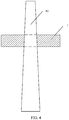
- a ring in the middle of the pole-mounted power supply may also be gradient, so that the ring can be naturally fastened on the pole ( FIG. 4 ) based on gravity.
- a ring in the middle of the pole-mounted power supply is not got through, and an upper side is closed. In this case, the pole-mounted power supply may be fastened to the top of the support pole.
- auxiliary components such as a power management system (Battery Management System, BMS), a busbar, a heating film, and a necessary reinforcing piece are disposed in the annular tank in this embodiment of the present invention.
- BMS Battery Management System
- These power auxiliary components are located between the electrochemical cells, or located on an upper part of the electrochemical cell, or located on a lower part of the electrochemical cell, or located on a surface of the electrochemical cell. This is not specifically limited herein.
- the pole-mounted power supply is designed as the annular tank having the cylindrical cavity at the center, so that the pole-mounted power supply can encircle the support pole after being mounted on the support pole.
- the plurality of electrochemical cells of the pole-mounted power supply may be evenly arranged in the annular tank in a plurality of deployment manners, the center of gravity of the pole-mounted power supply can be located on the cross section (even the center) of the support pole. Therefore, through implementation of the embodiments of the present invention, stability of the pole-mounted power supply can be improved, and impact from severe weather is avoided.
- the electrochemical cells are evenly distributed, surrounding environments of all the electrochemical cells are basically consistent, and working temperature is also consistent, so that it is ensured that temperature between the electrochemical cells is consistent, in other words, heat dissipation situations of all the electrochemical cells are basically consistent, thereby avoiding a problem of local overheating caused by inconsistent heat dissipation between the electrochemical cells, and prolonging the service life of the pole-mounted power supply.
- the pole-mounted power supply provided in the embodiments of the present invention has relatively strong expandability, can be widely applicable to an application scenario with increasing requirements for an electric quantity such as a 5G scenario, and has relatively strong applicability.
- an embodiment of the present invention provides a ring-shaped columnar pole-mounted power supply.
- the ring-shaped columnar pole-mounted power supply includes an annular tank 1 to be mounted on a support pole (for example, a column such as a street lamp), a plurality of electrochemical cells (not shown in FIG. 2 ) disposed in internal space 2 of the annular tank 1, and a movable hinge 5 and a fastening structure 6 that are disposed on the annular tank 1.
- a cylindrical cavity 20 at a center of the annular tank 1, and the cylindrical cavity 20 may be configured to encircle the support pole.
- the plurality of electrochemical cells are evenly and symmetrically arranged in the internal space 2 of the annular tank 1 (this is described in detail below).
- a center of gravity of the pole-mounted power supply can be located inside the support pole.
- the support pole is vertically disposed on the ground, and when the pole-mounted power supply is mounted on the support pole, the center of gravity of the pole-mounted power supply is located on a cross section of the support pole.
- the cross section is located inside the support pole, and the cross section is perpendicular to a center line of the cylindrical cavity 20.
- centers of gravity of the plurality of electrochemical cells are evenly distributed around the center line of the cylindrical cavity 20.
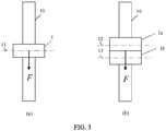
- the center of gravity (F) of the pole-mounted power supply is located on a cross section 11 of the support pole 10.
- the center of gravity of the pole-mounted power supply even can be located at a center of the cross section 11 of the support pole 10.
- the movable hinge 5 and the fastening structure 6 are disposed on the annular tank 1 of the pole-mounted power supply, and the annular tank may be divided into two semi-circular columnar structures (201 and 202).
- the movable hinge 5 is disposed at a junction (an overlapping position) of ends of the two semi-circular columnar structures, and the two semi-circular columnar structures are movably connected by using the movable hinge 5.
- the adjustable fastening structure 6 is disposed at a junction (an overlapping position) of the other ends of the two semi-circular columnar structures, and when the two semi-circular columnar structures are closed into the annular tank 1 by using the movable hinge 5, the adjustable fastening structure 6 is configured to lock the annular tank 1. Because the pole-mounted power supply (the annular tank 1) can be opened into the two semi-circular columnar structures based on the movable hinge 5, it is convenient to arrange the electrochemical cells in the corresponding internal space 2, and it is convenient to mount the pole-mounted power supply on the support pole.
- the pole-mounted power supply provided in this embodiment of the present invention may be designed as a multi-layer combination form based on a requirement.
- the pole-mounted power supply may be designed as two layers: a top layer and a bottom layer, and the layers each include a ring-shaped columnar pole-mounted power supply shown in FIG. 2 : a pole-mounted power supply 1a and 1 pole-mounted power supply 1b.
- a center of gravity of the pole-mounted power supply 1a is located on a cross section 12 of the support pole 10
- a center of gravity of the pole-mounted power supply 1b is located on a cross section 13 of the support pole 10. Therefore, an overall center of gravity of the pole-mounted power supply is still located on the cross section of the support pole 10 and even at a center.
- auxiliary components such as a power management system (Battery Management System, BMS), a busbar, a heating film, and a necessary reinforcing piece are disposed in the annular tank 1 in this embodiment of the present invention.
- BMS Battery Management System
- These power auxiliary components are located between the electrochemical cells, or located on an upper part of the electrochemical cell, or located on a lower part of the electrochemical cell, or located on a surface of the electrochemical cell. This is not specifically limited herein.
- the center of gravity of the ring-shaped columnar pole-mounted power supply in this embodiment of the present invention can be kept on the cross section of the support pole 10.
- the pole-mounted power supply may be mounted on the support pole 10 in various manners. Before mounting, the movable hinge 5 is in a movable connection state, and after mounting, the movable hinge 5 is fixedly fastened to the adjustable fastening structure 6 on the other end.
- the pole-mounted power supply may be fastened to the support pole 10 based on a structure of the pole-mounted power supply, or may be fastened to the support pole 10 by using a peripheral upper base component and a peripheral lower base component.
- the cylindrical cavity 20 may be configured to clamp the support pole 10.
- the pole-mounted power supply the annular tank 1
- the adjustable fastening structure 6 is fastened, so that a cavity wall of the cylindrical cavity 20 can be in close contact with the support pole 10.
- a radius of the cylindrical cavity 20 is equal to a radius of a mounting position of the support pole 10. In this way, the pole-mounted power supply can be fastened to the support pole 10 by using friction between the cavity wall and the support pole 10.
- such a form of clamping the support pole is not only applicable to fastening of the pole-mounted power supply on a cylindrical support pole 10, but also applicable to fastening of the pole-mounted power supply on a non-cylindrical (with a variant cross section) support pole 10.
- the pole-mounted power supply may be fastened to the support pole 10 by using a peripheral component.
- a peripheral component As shown in FIG. 5 , an angle steel 8 is disposed on each of two ends of the cylindrical cavity 20 of the annular tank 1 of the pole-mounted power supply (in other words, the angle steel 8 is disposed on each of a top edge and a bottom edge of a cavity part of each semi-circular columnar structure).
- angle steel 8 When the pole-mounted power supply needs to be mounted on the support pole 10, one side of the angle steel 8 is fixedly connected to the annular tank 1 (the angle steel 8 is fastened to form an upper fastening base and a lower fastening base), and the other side of the angle steel 8 is in close contact with the support pole 10. Angle steels 8 on top edges of cavity parts of the two semi-circular columnar structures are separately set to be connected by using fastening studs 9, and angle steels 8 on bottom edges of the cavity parts of the two semi-circular columnar structures are also separately set to be connected by using fastening studs 9. In this way, after being mounted, the pole-mounted power supply may be fastened to the support pole 10 by using a peripheral component.
- the radius of the cylindrical cavity 20 (in other words, an inner diameter of the annular tank 1) is not less than a radius of the encircled cross section of the support pole, and height of the annular tank 1 is not less than height of the electrochemical cells disposed inside the annular tank 1.
- the pole-mounted power supply is designed as the annular tank having the cylindrical cavity at the center, so that the pole-mounted power supply can encircle the support pole after being mounted on the support pole.
- the plurality of electrochemical cells of the pole-mounted power supply are evenly arranged in the annular tank, the center of gravity of the pole-mounted power supply can be located on the cross section (even the center) of the support pole. Therefore, through implementation of this embodiment of the present invention, stability of the pole-mounted power supply can be improved.
- FIG. 6 is a top view of a pole-mounted power supply according to an embodiment of the present invention.
- a plurality of electrochemical cells 3 (in the figure, 16 electrochemical cells 3) are arranged in internal space 2 of an annular tank 1, each electrochemical cell 3 has an electrochemical cell tab 4, the electrochemical cell tab is arranged upwards on a surface of the electrochemical cell, and busbars of electrochemical cell tabs of different electrochemical cells are connected by using a soft connection (for example, a wire connection) or a hard connection (for example, a copper sheet connection).
- a soft connection for example, a wire connection
- a hard connection for example, a copper sheet connection
- electrochemical cell tabs 41 and 42 of adjacent electrochemical cells near the movable hinge 5 are connected by using a soft connection, and similarly, electrochemical cell tabs near the adjustable fastening structure 6 are also connected by using a soft connection.
- Centers of gravity of these electrochemical cells are evenly distributed around a center line of a cylindrical cavity 20 of the annular tank 1.
- these electrochemical cells are square electrochemical cells or soft-package electrochemical cells, and these electrochemical cells are radially distributed in the internal space 2 around the center line of the cylindrical cavity 20.
- a maximum cross section (indicated by 71 or 72) of each electrochemical cell is coplanar with the center line of the cylindrical cavity 20.
- An included angle between respective maximum cross sections (for example, between 71 and 72) of adjacent electrochemical cells is an included angle 7 shown in the figure. Because the electrochemical cells are evenly distributed around a center line of the support pole, the included angle 7 between the electrochemical cells is 22.5°, and a sum of included angles 7 is 360°.
- n layers of pole-mounted power supplies may be arranged based on an actual power consumption requirement with reference to a form in (b) in FIG. 3 .
- a sum of included angles 7 of all the pole-mounted power supplies is n times 360°, where n is an integer greater than or equal to 1.
- FIG. 7 An opening state and a closed state of the ring-shaped columnar pole-mounted power supply are further described below.
- FIG. 7 is a top view showing that the pole-mounted power supply is divided into two semi-circular columnar structures
- (b) in FIG. 7 is a top view of an opening state of the pole-mounted power supply
- (c) in FIG. 7 is a top view of a closed state of the pole-mounted power supply.
- the annular tank of the pole-mounted power supply includes two semi-circular columnar structures 202 and 202 through combination.
- a constituent structure 51 of the movable hinge 5 is disposed on one end of the semi-circular columnar structure 201
- a constituent structure 52 of the movable hinge 5 is disposed on one end of the semi-circular columnar structure 202
- the constituent structure 51 and the constituent structure 52 may form a hinge structure 5 by using a movable connection, so that the two semi-circular columnar structures 201 and 202 are movably connected by using the movable hinge 5.
- a constituent structure 61 of the adjustable fastening structure 6 is disposed on the other end of the semi-circular columnar structure 201
- a constituent structure 62 of the adjustable fastening structure 6 is disposed on the other end of the semi-circular columnar structure 202
- the constituent structure 61 and the constituent structure 62 may overlap, and are adjustably fastened by using a relevant component, to form the adjustable fastening structure 6.
- the constituent structure 61 and the constituent structure 62 form a stud, and the stud may be adjustably fastened by using a nut, to form the adjustable fastening structure 6.
- the adjustable fastening structure 6 is configured to lock the annular tank 1.
- the pole-mounted power supply (the annular tank 1) may be opened into two semi-circular columnar structures 201 and 202 based on the movable hinge 5, so that it is convenient to arrange the electrochemical cells in internal space corresponding to 201 and internal space corresponding to 202.
- a half quantity of electrochemical cells 3 may be disposed in each of the two semi-circular columnar structures 201 and 202 (each has eight groups of electrochemical cells in the figure).
- the pole-mounted power supply When the pole-mounted power supply is mounted on the support pole, the two semi-circular columnar structures 201 and 202 are closed, and in this case, the cylindrical cavity 20 encircles the support pole. Then, the adjustable fastening structure 6 is locked, and in this case, the pole-mounted power supply may be fastened to the support pole in a manner shown in the embodiment in FIG. 4 or FIG. 5 .
- FIG. 8 is a top view of another pole-mounted power supply according to an embodiment of the present invention.
- a plurality of electrochemical cells 14 (in the figure, 8 electrochemical cells 3) are arranged in internal space 2 of an annular tank 1, each electrochemical cell 14 has an electrochemical cell tab 15, the electrochemical cell tab 15 is arranged upwards on a surface of the electrochemical cell, and busbars of electrochemical cell tabs of different electrochemical cells are connected by using a soft connection (for example, a wire connection) or a hard connection (for example, a copper sheet connection).
- a soft connection for example, a wire connection
- a hard connection for example, a copper sheet connection
- electrochemical cell tabs of adjacent electrochemical cells near the movable hinge 5 and the adjustable fastening structure 6 are connected by using a soft connection. Centers of gravity of these electrochemical cells are evenly distributed around a center line of a cylindrical cavity 20 of the annular tank 1.
- these electrochemical cells are square electrochemical cells or soft-package electrochemical cells, and these electrochemical cells are distributed in the internal space 2 around the center line of the cylindrical cavity 20 in a rotary (or helical) manner, and a maximum cross section of the electrochemical cell is not coplanar with the center line of the cylindrical cavity 20.
- An included angle between respective maximum cross sections of adjacent electrochemical cells is an included angle 16 shown in the figure. Because the electrochemical cells are evenly distributed around a center line of the support pole, the included angle 16 between the electrochemical cells is 45°, and a sum of included angles 16 is 360°.
- n layers of pole-mounted power supplies may be arranged based on an actual power consumption requirement with reference to a form in (b) in FIG. 3 .
- a sum of included angles 16 of all the pole-mounted power supplies is n times 360°, where n is an integer greater than or equal to 1.
- such a ring-shaped columnar pole-mounted power supply may also be divided into two semi-circular columnar structures (not shown in the figure), and the two semi-circular columnar structures may be opened and closed based on the movable hinge 5.
- the adjustable fastening structure 6 is configured to lock the pole-mounted power supply.
- FIG. 9 is a top view of another pole-mounted power supply according to an embodiment of the present invention.
- a plurality of electrochemical cells 17 (in the figure, 64 electrochemical cells 17) are arranged in internal space 2 of an annular tank 1, each electrochemical cell 17 has an electrochemical cell tab 18, the electrochemical cell tab 18 is arranged upwards on a surface of the electrochemical cell, and busbars of electrochemical cell tabs of different electrochemical cells are connected by using a soft connection (for example, a wire connection) or a hard connection (for example, a copper sheet connection).
- a soft connection for example, a wire connection
- a hard connection for example, a copper sheet connection
- electrochemical cell tabs of adjacent electrochemical cells near the movable hinge 5 and the adjustable fastening structure 6 are connected by using a soft connection. Centers of gravity of these electrochemical cells are evenly distributed around a center line of a cylindrical cavity 20 of the annular tank 1. Specifically, these electrochemical cells are cylindrical electrochemical cells. A center line of each cylindrical electrochemical cell is parallel to the center line of the cylindrical cavity 20. These electrochemical cells are radially distributed in the internal space 2 around the center line of the cylindrical cavity 20, and one group of electrochemical cells (in the figure, one group of electrochemical cells include four electrochemical cells) are disposed on each radial line.
- a plane constituted by a center line of a group of electrochemical cells on a same radial line and the center line of the cylindrical cavity is 191
- a plane constituted by a center line of a group of electrochemical cells on adjacent radiation lines and the center line of the cylindrical cavity is 192
- an included angle between 191 and 192 is an included angle 19. Because each group of electrochemical cells are evenly distributed around a center line of the support pole, the included angle 19 is 22.5°, and a sum of these included angles 16 is 360°.
- n layers of pole-mounted power supplies may be arranged based on an actual power consumption requirement with reference to a form in (b) in FIG. 3 .
- a sum of included angles 16 of all the pole-mounted power supplies is n times 360°, where n is an integer greater than or equal to 1.
- such a ring-shaped columnar pole-mounted power supply may also be divided into two semi-circular columnar structures (not shown in the figure), and the two semi-circular columnar structures may be opened and closed based on the movable hinge 5.
- the adjustable fastening structure 6 is configured to lock the pole-mounted power supply.
- the electrochemical cells 14 may be arranged in a uniformly spiral rising manner along a direction of the center line of the cylindrical cavity 20.
- a sum of included angles 16 of all pole-mounted power supplies may be m times 360°, where m is an integer greater than 1.
- the pole-mounted power supply may include a plurality of layers of annular tanks, and each layer of annular tank may be separately combined and designed by using any one of the embodiments in FIG. 6 , FIG. 8 , and FIG. 9 and other variant embodiments. Such a combination manner also falls within the protection scope of the present invention.
- the centers of gravity of the plurality of electrochemical cells described in the embodiments of the present invention are evenly distributed around the center line of the cylindrical cavity, in a possible embodiment, in addition to the evenly distributed electrochemical cells in the annular tank of the pole-mounted power supply, it is also possible to dispose a few non-evenly distributed electrochemical cells based on a requirement. In this case, the center of gravity of the pole-mounted power supply can still be located inside the support pole.
- the pole-mounted power supply is designed as the annular tank having the cylindrical cavity at the center, so that the pole-mounted power supply can encircle the support pole after being mounted on the support pole.
- the plurality of electrochemical cells of the pole-mounted power supply may be evenly arranged in the annular tank in a plurality of deployment manners, the center of gravity of the pole-mounted power supply can be located on the cross section (even the center) of the support pole. Therefore, through implementation of the embodiments of the present invention, stability of the pole-mounted power supply can be improved, and impact from severe weather is avoided.
- the electrochemical cells are evenly distributed, surrounding environments of all the electrochemical cells are basically consistent, and working temperature is also consistent, so that it is ensured that temperature between the electrochemical cells is consistent, in other words, heat dissipation situations of all the electrochemical cells are basically consistent, thereby avoiding a problem of local overheating caused by inconsistent heat dissipation between the electrochemical cells, and prolonging a service life of the pole-mounted power supply.
- the pole-mounted power supply provided in the embodiments of the present invention has relatively strong expandability, can be widely applicable to an application scenario with increasing requirements for an electric quantity such as a 5G scenario, and has relatively strong applicability.
Landscapes
- Chemical & Material Sciences (AREA)
- Chemical Kinetics & Catalysis (AREA)
- Electrochemistry (AREA)
- General Chemical & Material Sciences (AREA)
- Engineering & Computer Science (AREA)
- Manufacturing & Machinery (AREA)
- General Engineering & Computer Science (AREA)
- Mechanical Engineering (AREA)
- Microelectronics & Electronic Packaging (AREA)
- Battery Mounting, Suspending (AREA)
Abstract
Description
- The present invention relates to the field of power supply technologies, and in particular, to a pole-mounted power supply.
- Currently, with the gradual popularization and commercial use of 4G/5G and the development of network technologies such as the Internet of Things and self-driving, there is a very large demand for a pole-mounted secondary power supply (a pole-mounted power supply for short) used to supply power to a radio frequency transmitter, a camera, a signal light, and the like. In an outdoor environment, an existing pole-mounted power supply is usually designed as a square, and is mounted on a side face of a support pole (such as a utility pole). As shown in
FIG. 1 , the pole-mounted power supply includes a square power supply box and a component such as an electrochemical cell arranged in the power supply box, and is hung on the side face of the support pole after being mounted by using a connecting piece. However, because the pole-mounted power supply is usually relatively heavy, such a designing and mounting manner has disadvantages such as an unstable center of gravity and a large frontal area. Especially in severe weather, the pole-mounted power supply has a risk of falling, and stability is relatively poor. In addition, in the power supply box of the square pole-mounted power supply, arrangement of electrochemical cells is usually similar to a conventional electrochemical cell arrangement manner. To be specific, a plurality of groups of electrochemical cells are used in parallel, and the plurality of groups of electrochemical cells are arranged together in a form of close arrangement in a stack. However, in this arrangement manner, heat dissipation between the electrochemical cells is not even, a temperature difference between the electrochemical cells is large, and in a battery charging and discharging process, local overheating is easily caused. Consequently, performance and a service life of a local electrochemical cell are reduced, and a security risk problem is even easily caused due to local overheating. - Embodiments of the present invention provide a pole-mounted power supply, so that stability of the pole-mounted power supply can be improved, and a problem of local overheating caused by inconsistent heat dissipation between electrochemical cells in the pole-mounted power supply is avoided, thereby prolonging a service life of the pole-mounted power supply.
- According to a first aspect, an embodiment of the present invention provides a pole-mounted power supply. The pole-mounted power supply includes an annular tank to be mounted on a support pole, there is a cylindrical cavity at a center of the annular tank, the cylindrical cavity is configured to encircle the support pole, a plurality of electrochemical cells are evenly disposed in the annular tank, and a center of gravity of the pole-mounted power supply is located on a cross section of the support pole when the pole-mounted power supply is mounted on the support pole. Specifically, in the annular tank, centers of gravity of the plurality of electrochemical cells are evenly distributed around a center line of the cylindrical cavity. In this way, when the pole-mounted power supply is mounted on the support pole, the center of gravity (F) of the pole-mounted power supply is located on the cross section of the support pole. In a possible embodiment, the center of gravity of the pole-mounted power supply even can be located at a center of the cross section of the support pole. The cross section is located inside the support pole, and the cross section is perpendicular to the center line of the cylindrical cavity.
- It can be learned that, in this embodiment of the present invention, the pole-mounted power supply is designed as the annular tank having the cylindrical cavity at the center, so that the pole-mounted power supply can encircle the support pole after being mounted on the support pole. In addition, because the plurality of electrochemical cells of the pole-mounted power supply are evenly arranged in the annular tank, the center of gravity of the pole-mounted power supply can be located on the cross section (even the center) of the support pole. Therefore, through implementation of this embodiment of the present invention, stability of the pole-mounted power supply can be improved. In addition, because the electrochemical cells are evenly distributed, surrounding environments of all the electrochemical cells are basically consistent, and therefore, heat dissipation situations of all the electrochemical cells are also basically consistent, thereby avoiding a problem of local overheating caused by inconsistent heat dissipation between the electrochemical cells, and prolonging a service life of the pole-mounted power supply.
- In an implementation of the present invention, the annular tank is divided into two semi-circular columnar structures, a movable hinge is disposed at a first junction of the two semi-circular columnar structures, and the two semi-circular columnar structures are movably connected by using the movable hinge. An adjustable fastening structure is disposed at a second junction of the two semi-circular columnar structures, and when the two semi-circular columnar structures are closed into the annular tank by using the movable hinge, the adjustable fastening structure is configured to lock the annular tank.
- In this embodiment of the present invention, that a plurality of electrochemical cells are evenly disposed in the annular tank is specifically: in the annular tank, centers of gravity of the plurality of electrochemical cells are evenly distributed around the center line of the cylindrical cavity. Specifically, the plurality of electrochemical cells in internal space of the annular tank have various arrangement manners.
- In a possible arrangement manner, a plurality of square electrochemical cells or soft-package electrochemical cells (for example, 16 square electrochemical cells) are arranged in the internal space of the annular tank, each electrochemical cell has an electrochemical cell tab, the electrochemical cell tab is arranged upwards on a surface of the electrochemical cell, and busbars of electrochemical cell tabs of different electrochemical cells are connected by using a soft connection (for example, a wire connection) or a hard connection (for example, a copper sheet connection). Centers of gravity of these electrochemical cells are evenly distributed around the center line of the cylindrical cavity of the annular tank. Specifically, these electrochemical cells are radially distributed in the internal space around the center line of the cylindrical cavity. A maximum cross section of each electrochemical cell is coplanar with the center line of the cylindrical cavity. An included angle between respective maximum cross sections of adjacent electrochemical cells is 22.5°, and a sum of these included angles is 360°. In a possible embodiment, n layers of pole-mounted power supplies may be designed based on an actual power consumption requirement. In this case, it may be understood that a sum of included
angles 7 of all the pole-mounted power supplies is n times 360°, where n is an integer greater than or equal to 1. - In another possible arrangement manner, a plurality of square electrochemical cells or soft-package electrochemical cells (for example, eight square electrochemical cells) are arranged in the internal space of the annular tank, each electrochemical cell has an electrochemical cell tab, the electrochemical cell tab is arranged upwards on a surface of the electrochemical cell, and busbars of electrochemical cell tabs of different electrochemical cells are connected by using a soft connection (for example, a wire connection) or a hard connection (for example, a copper sheet connection). Specifically, these electrochemical cells are distributed in the internal space around the center line of the cylindrical cavity in a rotary (or helical) manner, and a maximum cross section of the electrochemical cell is not coplanar with the center line of the cylindrical cavity. An included angle between respective maximum cross sections of adjacent electrochemical cells is 45°, and a sum of these included angles is 360°. In a possible embodiment, n layers of pole-mounted power supplies may be designed based on an actual power consumption requirement. In this case, it may be understood that a sum of included
angles 16 of all the pole-mounted power supplies is n times 360°, where n is an integer greater than or equal to 1. - In still another possible arrangement manner, a plurality of cylindrical electrochemical cells (for example, 64 electrochemical cells) are arranged in the internal space of the annular tank, each electrochemical cell has an electrochemical cell tab, the electrochemical cell tab is arranged upwards on a surface of the electrochemical cell, and busbars of electrochemical cell tabs of different electrochemical cells are connected by using a soft connection (for example, a wire connection) or a hard connection (for example, a copper sheet connection). Centers of gravity of these electrochemical cells are evenly distributed around the center line of the cylindrical cavity of the annular tank. Specifically, a center line of each cylindrical electrochemical cell is parallel to the center line of the cylindrical cavity. These electrochemical cells are radially distributed in the internal space around the center line of the cylindrical cavity, and one group of electrochemical cells are evenly disposed on each radial line. An included angle between a plane constituted by a center line of a group of electrochemical cells on a same radial line and the center line of the cylindrical cavity and a plane constituted by a center line of a group of electrochemical cells on adjacent radial lines and the center line of the cylindrical cavity is 22.5°, and a sum of these included
angles 16 is 360°. - In a possible embodiment, n layers of pole-mounted power supplies may be designed based on an actual power consumption requirement. In this case, it may be understood that a sum of included angles of all the pole-mounted power supplies is n times 360°, where n is an integer greater than or equal to 1.
- In addition, in this embodiment of the present invention, the pole-mounted power supply may be mounted on the support pole in various manners. Before mounting, the movable hinge is in a movable connection state, and after mounting, the movable hinge is fixedly fastened to the adjustable fastening structure on the other end. The pole-mounted power supply may be fastened to the support pole based on a structure of the pole-mounted power supply, or may be fastened to the support pole by using a peripheral upper base component and a peripheral lower base component.
- In a possible mounting manner, the cylindrical cavity may be configured to clamp the support pole. When the pole-mounted power supply is mounted on the support pole, the adjustable fastening structure is fastened, so that a cavity wall of the cylindrical cavity can be in close contact with the support pole. In other words, when the pole-mounted power supply is mounted on the support pole, a radius of the cylindrical cavity is equal to a radius of a mounting position of the support pole. In this way, the pole-mounted power supply can be fastened to the support pole by using friction between the cavity wall and the support pole.
- In another possible mounting manner, the pole-mounted power supply may be fastened to the support pole by using a peripheral component. For example, an angle steel is disposed on each of two ends of the cylindrical cavity of the annular tank of the pole-mounted power supply (in other words, the angle steel is disposed on each of a top edge and a bottom edge of a cavity part of each semi-circular columnar structure). When the pole-mounted power supply needs to be mounted on the support pole, one side of the angle steel is fixedly connected to the annular tank, and the other side of the angle steel is in close contact with the support pole. Angle steels on top edges of cavity parts of the two semi-circular columnar structures are separately set to be connected by using fastening studs, and angle steels on bottom edges of the cavity parts of the two semi-circular columnar structures are also separately set to be connected by using fastening studs. In this way, after being mounted, the pole-mounted power supply may also be fastened to the support pole by using a peripheral component.
- In another application case, the support pole is not standardized, and the support pole has different diameters. Actually, regardless of a change of the support pole, at least one second support pole with a standard diameter may be connected. In this case, the pole-mounted power supply may also be mounted on the second support pole. In this case, an equivalent effect is achieved. In still another application case, there are uneven diameters on a top part and a bottom part of the support pole. Generally, the diameter gradually decreases from bottom to top. In this case, a ring in the middle of the pole-mounted power supply may also be gradient, so that the ring can be naturally fastened on the pole (
FIG. 4 ) based on gravity. In another possible case, a ring in the middle of the pole-mounted power supply is not got through, and an upper side is closed. In this case, the pole-mounted power supply may be fastened to the top of the support pole. - In specific implementation, in addition to the electrochemical cells, other conventional power auxiliary components such as a power management system (Battery Management System, BMS), a busbar, a heating film, and a necessary reinforcing piece are disposed in the annular tank in this embodiment of the present invention. These power auxiliary components are located between the electrochemical cells, or located on an upper part of the electrochemical cell, or located on a lower part of the electrochemical cell, or located on a surface of the electrochemical cell. This is not specifically limited herein.
- It can be learned that, in the embodiments of the present invention, the pole-mounted power supply is designed as the annular tank having the cylindrical cavity at the center, so that the pole-mounted power supply can encircle the support pole after being mounted on the support pole. In addition, because the plurality of electrochemical cells of the pole-mounted power supply may be evenly arranged in the annular tank in a plurality of deployment manners, the center of gravity of the pole-mounted power supply can be located on the cross section (even the center) of the support pole. Therefore, through implementation of the embodiments of the present invention, stability of the pole-mounted power supply can be improved, and impact from severe weather is avoided. In addition, because the electrochemical cells are evenly distributed, surrounding environments of all the electrochemical cells are basically consistent, and working temperature is also consistent, so that it is ensured that temperature between the electrochemical cells is consistent, in other words, heat dissipation situations of all the electrochemical cells are basically consistent, thereby avoiding a problem of local overheating caused by inconsistent heat dissipation between the electrochemical cells, and prolonging the service life of the pole-mounted power supply. In addition, it can be learned from the plurality of deployment manners of the electrochemical cells described above that the pole-mounted power supply provided in the embodiments of the present invention has relatively strong expandability, can be widely applicable to an application scenario with increasing requirements for an electric quantity such as a 5G scenario, and has relatively strong applicability.
- To describe the technical solutions in the embodiments of the present invention or in the background more clearly, the following briefly describes the accompanying drawings required for describing the embodiments of the present invention or the background.
-
FIG. 1 is a schematic diagram of an application scenario of a pole-mounted power supply in the prior art; -
FIG. 2 is a schematic structural diagram of a pole-mounted power supply according to an embodiment of the present invention; -
FIG. 3 is a schematic diagram of an application scenario of a pole-mounted power supply according to an embodiment of the present invention; -
FIG. 4 is a schematic diagram of a mounting manner of a pole-mounted power supply according to an embodiment of the present invention; -
FIG. 5 is a schematic diagram of a mounting manner of another pole-mounted power supply according to an embodiment of the present invention; -
FIG. 6 is a schematic structural diagram of another pole-mounted power supply according to an embodiment of the present invention; -
FIG. 7 is a schematic diagram of an application scenario of an opening and closing scenario of a pole-mounted power supply according to an embodiment of the present invention; -
FIG. 8 is a schematic structural diagram of still another pole-mounted power supply according to an embodiment of the present invention; and -
FIG. 9 is a schematic structural diagram of yet another pole-mounted power supply according to an embodiment of the present invention. - The following describes the embodiments of the present invention with reference to the accompanying drawings in the embodiments of the present invention. Terms used in implementations of the present invention are merely used to explain specific embodiments of the present invention, and are not intended to limit the present invention.
- Referring to
FIG. 2 , an embodiment of the present invention provides a ring-shaped columnar pole-mounted power supply. As shown inFIG. 2 , the ring-shaped columnar pole-mounted power supply includes anannular tank 1 to be mounted on a support pole (for example, a column such as a street lamp), a plurality of electrochemical cells (not shown inFIG. 2 ) disposed ininternal space 2 of theannular tank 1, and amovable hinge 5 and afastening structure 6 that are disposed on theannular tank 1. There is acylindrical cavity 20 at a center of theannular tank 1, and thecylindrical cavity 20 may be configured to encircle the support pole. The plurality of electrochemical cells are evenly and symmetrically arranged in theinternal space 2 of the annular tank 1 (this is described in detail below). In this way, when the pole-mounted power supply is mounted on the support pole, a center of gravity of the pole-mounted power supply can be located inside the support pole. In other words, the support pole is vertically disposed on the ground, and when the pole-mounted power supply is mounted on the support pole, the center of gravity of the pole-mounted power supply is located on a cross section of the support pole. The cross section is located inside the support pole, and the cross section is perpendicular to a center line of thecylindrical cavity 20. - Specifically, in the
annular tank 1, centers of gravity of the plurality of electrochemical cells are evenly distributed around the center line of thecylindrical cavity 20. In this way, as shown in (a) inFIG. 3 , when the pole-mounted power supply (indicated by the annular tank 1) is mounted on asupport pole 10, the center of gravity (F) of the pole-mounted power supply is located on a cross section 11 of thesupport pole 10. In a possible embodiment, the center of gravity of the pole-mounted power supply even can be located at a center of the cross section 11 of thesupport pole 10. - In this embodiment of the present invention, the
movable hinge 5 and thefastening structure 6 are disposed on theannular tank 1 of the pole-mounted power supply, and the annular tank may be divided into two semi-circular columnar structures (201 and 202). Themovable hinge 5 is disposed at a junction (an overlapping position) of ends of the two semi-circular columnar structures, and the two semi-circular columnar structures are movably connected by using themovable hinge 5. Theadjustable fastening structure 6 is disposed at a junction (an overlapping position) of the other ends of the two semi-circular columnar structures, and when the two semi-circular columnar structures are closed into theannular tank 1 by using themovable hinge 5, theadjustable fastening structure 6 is configured to lock theannular tank 1. Because the pole-mounted power supply (the annular tank 1) can be opened into the two semi-circular columnar structures based on themovable hinge 5, it is convenient to arrange the electrochemical cells in the correspondinginternal space 2, and it is convenient to mount the pole-mounted power supply on the support pole. - In a possible application scenario, the pole-mounted power supply provided in this embodiment of the present invention may be designed as a multi-layer combination form based on a requirement. For example, as shown in (b) in
FIG. 3 , in a combination form, the pole-mounted power supply may be designed as two layers: a top layer and a bottom layer, and the layers each include a ring-shaped columnar pole-mounted power supply shown inFIG. 2 : a pole-mountedpower supply 1a and 1 pole-mountedpower supply 1b. It may be understood that, a center of gravity of the pole-mounted power supply 1a is located on across section 12 of thesupport pole 10, and a center of gravity of the pole-mountedpower supply 1b is located on across section 13 of thesupport pole 10. Therefore, an overall center of gravity of the pole-mounted power supply is still located on the cross section of thesupport pole 10 and even at a center. - It should be noted that, in addition to the electrochemical cells, other conventional power auxiliary components such as a power management system (Battery Management System, BMS), a busbar, a heating film, and a necessary reinforcing piece are disposed in the
annular tank 1 in this embodiment of the present invention. These power auxiliary components are located between the electrochemical cells, or located on an upper part of the electrochemical cell, or located on a lower part of the electrochemical cell, or located on a surface of the electrochemical cell. This is not specifically limited herein. Regardless of an arrangement manner, because total weight of the electrochemical cells is a main part of weight of the pole-mounted power supply, the center of gravity of the ring-shaped columnar pole-mounted power supply in this embodiment of the present invention can be kept on the cross section of thesupport pole 10. - In this embodiment of the present invention, the pole-mounted power supply may be mounted on the
support pole 10 in various manners. Before mounting, themovable hinge 5 is in a movable connection state, and after mounting, themovable hinge 5 is fixedly fastened to theadjustable fastening structure 6 on the other end. The pole-mounted power supply may be fastened to thesupport pole 10 based on a structure of the pole-mounted power supply, or may be fastened to thesupport pole 10 by using a peripheral upper base component and a peripheral lower base component. - Referring to
FIG. 4 , in a possible embodiment, thecylindrical cavity 20 may be configured to clamp thesupport pole 10. When the pole-mounted power supply (the annular tank 1) is mounted on thesupport pole 10, theadjustable fastening structure 6 is fastened, so that a cavity wall of thecylindrical cavity 20 can be in close contact with thesupport pole 10. In other words, when the pole-mounted power supply is mounted on thesupport pole 10, a radius of thecylindrical cavity 20 is equal to a radius of a mounting position of thesupport pole 10. In this way, the pole-mounted power supply can be fastened to thesupport pole 10 by using friction between the cavity wall and thesupport pole 10. It may be understood that, such a form of clamping the support pole is not only applicable to fastening of the pole-mounted power supply on acylindrical support pole 10, but also applicable to fastening of the pole-mounted power supply on a non-cylindrical (with a variant cross section)support pole 10. - Referring to (a) to (c) in
FIG. 5 , in another possible embodiment, the pole-mounted power supply may be fastened to thesupport pole 10 by using a peripheral component. As shown inFIG. 5 , anangle steel 8 is disposed on each of two ends of thecylindrical cavity 20 of theannular tank 1 of the pole-mounted power supply (in other words, theangle steel 8 is disposed on each of a top edge and a bottom edge of a cavity part of each semi-circular columnar structure). When the pole-mounted power supply needs to be mounted on thesupport pole 10, one side of theangle steel 8 is fixedly connected to the annular tank 1 (theangle steel 8 is fastened to form an upper fastening base and a lower fastening base), and the other side of theangle steel 8 is in close contact with thesupport pole 10. Angle steels 8 on top edges of cavity parts of the two semi-circular columnar structures are separately set to be connected by usingfastening studs 9, and angle steels 8 on bottom edges of the cavity parts of the two semi-circular columnar structures are also separately set to be connected by usingfastening studs 9. In this way, after being mounted, the pole-mounted power supply may be fastened to thesupport pole 10 by using a peripheral component. - It should be noted that, to make the pole-mounted power supply more fastened to the
support pole 10, in a specific application scenario, there may be a plurality offastening studs 9 between the angle steels 8 disposed on the top edge of the cavity part, and there may be a plurality offastening studs 9 between the angle steels 8 disposed on the bottom edge of the cavity part. As shown in c inFIG. 5 , there may be fourfastening studs 9 between the angle steels 8 disposed on the top (bottom) edge of the cavity part, and the fourfastening studs 9 are separately connected between the angle steels 8, thereby fastening the pole-mounted power supply on thesupport pole 10. - It may be understood that, during specific implementation, the radius of the cylindrical cavity 20 (in other words, an inner diameter of the annular tank 1) is not less than a radius of the encircled cross section of the support pole, and height of the
annular tank 1 is not less than height of the electrochemical cells disposed inside theannular tank 1. - It can be learned that, in this embodiment of the present invention, the pole-mounted power supply is designed as the annular tank having the cylindrical cavity at the center, so that the pole-mounted power supply can encircle the support pole after being mounted on the support pole. In addition, because the plurality of electrochemical cells of the pole-mounted power supply are evenly arranged in the annular tank, the center of gravity of the pole-mounted power supply can be located on the cross section (even the center) of the support pole. Therefore, through implementation of this embodiment of the present invention, stability of the pole-mounted power supply can be improved. In addition, because the electrochemical cells are evenly distributed, surrounding environments of all the electrochemical cells are basically consistent, and therefore, heat dissipation situations of all the electrochemical cells are also basically consistent, thereby avoiding a problem of local overheating caused by inconsistent heat dissipation between the electrochemical cells, and prolonging a service life of the pole-mounted power supply.
- An arrangement manner of the plurality of electrochemical cells in the
internal space 2 of theannular tank 1 is described in detail below. - In a possible electrochemical cell arrangement manner,
FIG. 6 is a top view of a pole-mounted power supply according to an embodiment of the present invention. As shown inFIG. 6 , a plurality of electrochemical cells 3 (in the figure, 16 electrochemical cells 3) are arranged ininternal space 2 of anannular tank 1, eachelectrochemical cell 3 has an electrochemical cell tab 4, the electrochemical cell tab is arranged upwards on a surface of the electrochemical cell, and busbars of electrochemical cell tabs of different electrochemical cells are connected by using a soft connection (for example, a wire connection) or a hard connection (for example, a copper sheet connection). To facilitate opening and closing of theannular tank 1,electrochemical cell tabs movable hinge 5 are connected by using a soft connection, and similarly, electrochemical cell tabs near theadjustable fastening structure 6 are also connected by using a soft connection. Centers of gravity of these electrochemical cells are evenly distributed around a center line of acylindrical cavity 20 of theannular tank 1. Specifically, these electrochemical cells are square electrochemical cells or soft-package electrochemical cells, and these electrochemical cells are radially distributed in theinternal space 2 around the center line of thecylindrical cavity 20. A maximum cross section (indicated by 71 or 72) of each electrochemical cell is coplanar with the center line of thecylindrical cavity 20. An included angle between respective maximum cross sections (for example, between 71 and 72) of adjacent electrochemical cells is an includedangle 7 shown in the figure. Because the electrochemical cells are evenly distributed around a center line of the support pole, the includedangle 7 between the electrochemical cells is 22.5°, and a sum of includedangles 7 is 360°. - In a possible embodiment, n layers of pole-mounted power supplies may be arranged based on an actual power consumption requirement with reference to a form in (b) in
FIG. 3 . In this case, it may be understood that a sum of includedangles 7 of all the pole-mounted power supplies is n times 360°, where n is an integer greater than or equal to 1. - An opening state and a closed state of the ring-shaped columnar pole-mounted power supply are further described below. Referring to (a) to (c) in
FIG. 7 , (a) inFIG. 7 is a top view showing that the pole-mounted power supply is divided into two semi-circular columnar structures, (b) inFIG. 7 is a top view of an opening state of the pole-mounted power supply, and (c) inFIG. 7 is a top view of a closed state of the pole-mounted power supply. - As shown in (a) in
FIG. 7 , the annular tank of the pole-mounted power supply includes two semi-circularcolumnar structures constituent structure 51 of themovable hinge 5 is disposed on one end of the semi-circularcolumnar structure 201, aconstituent structure 52 of themovable hinge 5 is disposed on one end of the semi-circularcolumnar structure 202, and theconstituent structure 51 and theconstituent structure 52 may form ahinge structure 5 by using a movable connection, so that the two semi-circularcolumnar structures movable hinge 5. In addition, aconstituent structure 61 of theadjustable fastening structure 6 is disposed on the other end of the semi-circularcolumnar structure 201, aconstituent structure 62 of theadjustable fastening structure 6 is disposed on the other end of the semi-circularcolumnar structure 202, and theconstituent structure 61 and theconstituent structure 62 may overlap, and are adjustably fastened by using a relevant component, to form theadjustable fastening structure 6. For example, after overlapping, theconstituent structure 61 and theconstituent structure 62 form a stud, and the stud may be adjustably fastened by using a nut, to form theadjustable fastening structure 6. Theadjustable fastening structure 6 is configured to lock theannular tank 1. - As shown in (b) and (c) in
FIG. 7 , the pole-mounted power supply (the annular tank 1) may be opened into two semi-circularcolumnar structures movable hinge 5, so that it is convenient to arrange the electrochemical cells in internal space corresponding to 201 and internal space corresponding to 202. A half quantity ofelectrochemical cells 3 may be disposed in each of the two semi-circularcolumnar structures 201 and 202 (each has eight groups of electrochemical cells in the figure). In addition, it is also convenient to mount the pole-mounted power supply on the support pole from opened interspace. When the pole-mounted power supply is mounted on the support pole, the two semi-circularcolumnar structures cylindrical cavity 20 encircles the support pole. Then, theadjustable fastening structure 6 is locked, and in this case, the pole-mounted power supply may be fastened to the support pole in a manner shown in the embodiment inFIG. 4 orFIG. 5 . - It may be understood that, in addition to these
electrochemical cells 3, other conventional power auxiliary components such as a BMS, a busbar, a heating film, and a necessary reinforcing piece are arranged in theannular tank 1 in this embodiment of the present invention. These power auxiliary components are located between the electrochemical cells, or located on an upper part of the electrochemical cell, or located on a lower part of the electrochemical cell, or located on a surface of the electrochemical cell. In addition, it may be further understood that anangle steel 8, afastening stud 9, and the like may be further disposed outside theannular tank 1, and this is not specifically limited herein. - In another possible electrochemical cell arrangement manner,
FIG. 8 is a top view of another pole-mounted power supply according to an embodiment of the present invention. As shown inFIG. 8 , a plurality of electrochemical cells 14 (in thefigure, 8 electrochemical cells 3) are arranged ininternal space 2 of anannular tank 1, eachelectrochemical cell 14 has anelectrochemical cell tab 15, theelectrochemical cell tab 15 is arranged upwards on a surface of the electrochemical cell, and busbars of electrochemical cell tabs of different electrochemical cells are connected by using a soft connection (for example, a wire connection) or a hard connection (for example, a copper sheet connection). To facilitate opening and closing of theannular tank 1, electrochemical cell tabs of adjacent electrochemical cells near themovable hinge 5 and theadjustable fastening structure 6 are connected by using a soft connection. Centers of gravity of these electrochemical cells are evenly distributed around a center line of acylindrical cavity 20 of theannular tank 1. Specifically, these electrochemical cells are square electrochemical cells or soft-package electrochemical cells, and these electrochemical cells are distributed in theinternal space 2 around the center line of thecylindrical cavity 20 in a rotary (or helical) manner, and a maximum cross section of the electrochemical cell is not coplanar with the center line of thecylindrical cavity 20. An included angle between respective maximum cross sections of adjacent electrochemical cells is an includedangle 16 shown in the figure. Because the electrochemical cells are evenly distributed around a center line of the support pole, the includedangle 16 between the electrochemical cells is 45°, and a sum of includedangles 16 is 360°. - In a possible embodiment, n layers of pole-mounted power supplies may be arranged based on an actual power consumption requirement with reference to a form in (b) in
FIG. 3 . In this case, it may be understood that a sum of includedangles 16 of all the pole-mounted power supplies is n times 360°, where n is an integer greater than or equal to 1. - Similarly, such a ring-shaped columnar pole-mounted power supply may also be divided into two semi-circular columnar structures (not shown in the figure), and the two semi-circular columnar structures may be opened and closed based on the
movable hinge 5. When the two semi-circular columnar structures are closed, theadjustable fastening structure 6 is configured to lock the pole-mounted power supply. For a specific implementation, refer to related descriptions in the embodiment inFIG. 7 . Details are not described herein again. - It may be understood that, in addition to these
electrochemical cells 3, other conventional power auxiliary components such as a BMS, a busbar, a heating film, and a necessary reinforcing piece are arranged in theannular tank 1 in this embodiment of the present invention. These power auxiliary components are located between the electrochemical cells, or located on an upper part of the electrochemical cell, or located on a lower part of the electrochemical cell, or located on a surface of the electrochemical cell. In addition, it may be further understood that anangle steel 8, afastening stud 9, and the like may be further disposed outside theannular tank 1, and this is not specifically limited herein. - In still another possible electrochemical cell arrangement manner,
FIG. 9 is a top view of another pole-mounted power supply according to an embodiment of the present invention. As shown inFIG. 9 , a plurality of electrochemical cells 17 (in the figure, 64 electrochemical cells 17) are arranged ininternal space 2 of anannular tank 1, eachelectrochemical cell 17 has anelectrochemical cell tab 18, theelectrochemical cell tab 18 is arranged upwards on a surface of the electrochemical cell, and busbars of electrochemical cell tabs of different electrochemical cells are connected by using a soft connection (for example, a wire connection) or a hard connection (for example, a copper sheet connection). To facilitate opening and closing of theannular tank 1, electrochemical cell tabs of adjacent electrochemical cells near themovable hinge 5 and theadjustable fastening structure 6 are connected by using a soft connection. Centers of gravity of these electrochemical cells are evenly distributed around a center line of acylindrical cavity 20 of theannular tank 1. Specifically, these electrochemical cells are cylindrical electrochemical cells. A center line of each cylindrical electrochemical cell is parallel to the center line of thecylindrical cavity 20. These electrochemical cells are radially distributed in theinternal space 2 around the center line of thecylindrical cavity 20, and one group of electrochemical cells (in the figure, one group of electrochemical cells include four electrochemical cells) are disposed on each radial line. As shown in the figure, a plane constituted by a center line of a group of electrochemical cells on a same radial line and the center line of the cylindrical cavity is 191, a plane constituted by a center line of a group of electrochemical cells on adjacent radiation lines and the center line of the cylindrical cavity is 192, and an included angle between 191 and 192 is an includedangle 19. Because each group of electrochemical cells are evenly distributed around a center line of the support pole, the includedangle 19 is 22.5°, and a sum of these includedangles 16 is 360°. - In a possible embodiment, n layers of pole-mounted power supplies may be arranged based on an actual power consumption requirement with reference to a form in (b) in
FIG. 3 . In this case, it may be understood that a sum of includedangles 16 of all the pole-mounted power supplies is n times 360°, where n is an integer greater than or equal to 1. - Similarly, such a ring-shaped columnar pole-mounted power supply may also be divided into two semi-circular columnar structures (not shown in the figure), and the two semi-circular columnar structures may be opened and closed based on the
movable hinge 5. When the two semi-circular columnar structures are closed, theadjustable fastening structure 6 is configured to lock the pole-mounted power supply. For a specific implementation, refer to related descriptions in the embodiment inFIG. 7 . Details are not described herein again. - It may be understood that, in addition to these
electrochemical cells 3, other conventional power auxiliary components such as a BMS, a busbar, a heating film, and a necessary reinforcing piece are arranged in theannular tank 1 in this embodiment of the present invention. These power auxiliary components are located between the electrochemical cells, or located on an upper part of the electrochemical cell, or located on a lower part of the electrochemical cell, or located on a surface of the electrochemical cell. In addition, it may be further understood that anangle steel 8, afastening stud 9, and the like may be further disposed outside theannular tank 1, and this is not specifically limited herein. - It should be noted that the foregoing embodiments are merely used to explain, not to limit, possible implementation solutions of the embodiments of the present invention. In actual application, a power supply structure, an electrochemical cell arrangement manner, and the like may be accordingly deformed and combined based on an idea of a technical solution of the present invention.
- For example, in a possible deformation, in the embodiment shown in
FIG. 8 , theelectrochemical cells 14 may be arranged in a uniformly spiral rising manner along a direction of the center line of thecylindrical cavity 20. In this way, a sum of includedangles 16 of all pole-mounted power supplies may be m times 360°, where m is an integer greater than 1. - For another example, the pole-mounted power supply may include a plurality of layers of annular tanks, and each layer of annular tank may be separately combined and designed by using any one of the embodiments in
FIG. 6 ,FIG. 8 , andFIG. 9 and other variant embodiments. Such a combination manner also falls within the protection scope of the present invention. - In addition, it should be further noted that, although the centers of gravity of the plurality of electrochemical cells described in the embodiments of the present invention are evenly distributed around the center line of the cylindrical cavity, in a possible embodiment, in addition to the evenly distributed electrochemical cells in the annular tank of the pole-mounted power supply, it is also possible to dispose a few non-evenly distributed electrochemical cells based on a requirement. In this case, the center of gravity of the pole-mounted power supply can still be located inside the support pole.
- It can be learned that, in the embodiments of the present invention, the pole-mounted power supply is designed as the annular tank having the cylindrical cavity at the center, so that the pole-mounted power supply can encircle the support pole after being mounted on the support pole. In addition, because the plurality of electrochemical cells of the pole-mounted power supply may be evenly arranged in the annular tank in a plurality of deployment manners, the center of gravity of the pole-mounted power supply can be located on the cross section (even the center) of the support pole. Therefore, through implementation of the embodiments of the present invention, stability of the pole-mounted power supply can be improved, and impact from severe weather is avoided. In addition, because the electrochemical cells are evenly distributed, surrounding environments of all the electrochemical cells are basically consistent, and working temperature is also consistent, so that it is ensured that temperature between the electrochemical cells is consistent, in other words, heat dissipation situations of all the electrochemical cells are basically consistent, thereby avoiding a problem of local overheating caused by inconsistent heat dissipation between the electrochemical cells, and prolonging a service life of the pole-mounted power supply. In addition, it can be learned from the plurality of deployment manners of the electrochemical cells described above that the pole-mounted power supply provided in the embodiments of the present invention has relatively strong expandability, can be widely applicable to an application scenario with increasing requirements for an electric quantity such as a 5G scenario, and has relatively strong applicability.
- In the foregoing embodiments, the description of each embodiment has respective focuses. For a part that is not described in detail in an embodiment, refer to related descriptions in other embodiments.
- The foregoing descriptions are specific embodiments of the present application, but are not intended to limit the protection scope of the present application. Any modification or replacement readily figured out by a person skilled in the art within the technical scope disclosed in the present application shall fall within the protection scope of the present application. Therefore, the protection scope of this application shall be subject to the protection scope of the claims.
Claims (15)
- A pole-mounted power supply, comprising an annular tank configured to be mounted on a support pole, wherein there is a cylindrical cavity at a center of the annular tank, the cylindrical cavity is configured to encircle the support pole, the annular tank comprises a plurality of evenly distributed electrochemical cells, and a center of gravity of the pole-mounted power supply is located inside the support pole when the pole-mounted power supply is mounted on the support pole.
- The pole-mounted power supply according to claim 1, wherein that a center of gravity of the pole-mounted power supply is located inside the support pole when the pole-mounted power supply is mounted on the support pole is specifically:
the support pole is vertically disposed on the ground, and the center of gravity of the pole-mounted power supply is located on a cross section of the support pole when the pole-mounted power supply is mounted on the support pole, wherein the cross section is located inside the support pole, and the cross section is perpendicular to a center line of the cylindrical cavity. - The pole-mounted power supply according to claim 1 or 2, wherein that a plurality of electrochemical cells are evenly disposed in the annular tank is specifically:
in the annular tank, centers of gravity of the plurality of electrochemical cells are all evenly distributed around the center line of the cylindrical cavity. - The pole-mounted power supply according to claim 3, wherein that centers of gravity of the plurality of electrochemical cells are evenly distributed around the center line of the cylindrical cavity is specifically:
the plurality of electrochemical cells are radially distributed around the center line of the cylindrical cavity. - The pole-mounted power supply according to claim 4, wherein the electrochemical cell is a square electrochemical cell or a soft-package electrochemical cell, a maximum cross section of the electrochemical cell is coplanar with the center line of the cylindrical cavity, and a sum of included angles between respective maximum cross sections of adjacent electrochemical cells is an integer multiple of 360 degrees.
- The pole-mounted power supply according to claim 3, wherein that centers of gravity of the plurality of electrochemical cells are evenly distributed around the center line of the cylindrical cavity is specifically:
the plurality of electrochemical cells are distributed around the center line of the cylindrical cavity in a rotary or helical manner. - The pole-mounted power supply according to claim 6, wherein the electrochemical cell is a square electrochemical cell or a soft-package electrochemical cell, a maximum cross section of the electrochemical cell is not coplanar with the center line of the cylindrical cavity, and a sum of included angles between respective maximum cross sections of adjacent electrochemical cells is an integer multiple of 360 degrees.
- The pole-mounted power supply according to claim 3, wherein the electrochemical cell is a cylindrical electrochemical cell, a center line of the cylindrical electrochemical cell is parallel to the center line of the cylindrical cavity, and a sum of included angles between planes constituted by the center line of the cylindrical cavity and respective center lines of adjacent electrochemical cells is an integer multiple of 360 degrees.
- The pole-mounted power supply according to any one of claims 1 to 8, wherein that the cylindrical cavity is configured to encircle the support pole includes:
when the pole-mounted power supply is mounted on the support pole, a radius of the cylindrical cavity is equal to a radius of a mounting position of the support pole, to encircle and clamp the support pole. - The pole-mounted power supply according to any one of claims 1 to 9, wherein that the center of gravity of the pole-mounted power supply is located on a cross section of the support pole when the pole-mounted power supply is mounted on the support pole is specifically:
the center of gravity of the pole-mounted power supply is located at a center of the cross section of the support pole when the pole-mounted power supply is mounted on the support pole. - The pole-mounted power supply according to any one of claims 1 to 10, wherein the annular tank is divided into two semi-circular columnar structures, a movable hinge is disposed at a first junction of the two semi-circular columnar structures, and the two semi-circular columnar structures are movably connected by using the movable hinge.
- The pole-mounted power supply according to claim 11, wherein an adjustable fastening structure is disposed at a second junction of the two semi-circular columnar structures, and when the two semi-circular columnar structures are closed into the annular tank by using the movable hinge, the adjustable fastening structure is configured to lock the annular tank.
- The pole-mounted power supply according to claim 11 or 12, wherein at least one angle steel is disposed on each of a top edge and a bottom edge of each semi-circular columnar structure; one end of the angle steel is fixedly connected to a semi-circular columnar structure in which the angle steel is located, and the other end is configured to be in close contact with the support pole; and angle steels respectively disposed on the two semi-circular columnar structures are connected by using a fastening stud, to mount the pole-mounted power supply on the support pole.
- The pole-mounted power supply according to any one of claims 1 to 13, wherein the electrochemical cell further comprises an electrochemical cell tab, and there is a soft connection between electrochemical cell tabs of adjacent electrochemical cells near the movable hinge.
- The pole-mounted power supply according to any one of claims 1 to 14, wherein the pole-mounted power supply further comprises a power management system BMS, a busbar, and a heating film, and the BMS, the busbar, and the heating film are disposed inside the annular tank.
Applications Claiming Priority (2)
| Application Number | Priority Date | Filing Date | Title |
|---|---|---|---|
| CN201810140896.1A CN108417746A (en) | 2018-02-09 | 2018-02-09 | A kind of pole power supply |
| PCT/CN2018/103689 WO2019153729A1 (en) | 2018-02-09 | 2018-08-31 | Pole-held power supply |
Publications (2)
| Publication Number | Publication Date |
|---|---|
| EP3745489A1 true EP3745489A1 (en) | 2020-12-02 |
| EP3745489A4 EP3745489A4 (en) | 2021-03-17 |
Family
ID=63128468
Family Applications (1)
| Application Number | Title | Priority Date | Filing Date |
|---|---|---|---|
| EP18904530.5A Withdrawn EP3745489A4 (en) | 2018-02-09 | 2018-08-31 | Pole-held power supply |
Country Status (4)
| Country | Link |
|---|---|
| US (1) | US20200365842A1 (en) |
| EP (1) | EP3745489A4 (en) |
| CN (1) | CN108417746A (en) |
| WO (1) | WO2019153729A1 (en) |
Families Citing this family (6)
| Publication number | Priority date | Publication date | Assignee | Title |
|---|---|---|---|---|
| CN108417746A (en) * | 2018-02-09 | 2018-08-17 | 华为技术有限公司 | A kind of pole power supply |
| CN109166999B (en) * | 2018-08-29 | 2021-06-22 | 义乌市君胜科技有限公司 | Explosion-proof module of lithium cell |
| CN109787307B (en) * | 2018-12-13 | 2020-09-01 | 浙江英丽科技有限公司 | Encircling type anti-typhoon emergency power supply |
| CN113451684A (en) * | 2021-07-30 | 2021-09-28 | 湖北亿纬动力有限公司 | Energy storage box |
| CN117239329B (en) * | 2023-09-13 | 2024-06-04 | 南京莱迪新能源科技有限公司 | Wall-mounted household lithium storage battery power supply assembly and installation method |
| CN117937028B (en) * | 2024-03-22 | 2024-06-14 | 蜂巢能源科技股份有限公司 | Ring battery module and battery pack |
Family Cites Families (9)
| Publication number | Priority date | Publication date | Assignee | Title |
|---|---|---|---|---|
| GB2354633A (en) * | 1998-12-11 | 2001-03-28 | Schlumberger Holdings | A method of sealing electrical cells which are used in a wellbore |
| CN101457860B (en) * | 2008-12-31 | 2012-07-04 | 苏州捷英特管道技术有限公司 | Damping and sealing tube joint |
| US10094525B2 (en) * | 2013-11-08 | 2018-10-09 | Philips Lighting Holding B.V. | Battery powered lighting system |
| CN203644845U (en) * | 2013-11-22 | 2014-06-11 | 北京豪利通达管理咨询有限责任公司 | Backup power supply device and mobile signal antenna device |
| CN205282580U (en) * | 2015-06-30 | 2016-06-01 | 孙煌敏 | A lithium-ion battery pack |
| CN205503637U (en) * | 2016-01-06 | 2016-08-24 | 河北鸿宇通信器材有限公司 | Hold hoop |
| CN205372474U (en) * | 2016-01-19 | 2016-07-06 | 长泰县达明灯具经营部 | Embrace rod -type large capacity solar street lamp battery |
| CN106229436A (en) * | 2016-08-30 | 2016-12-14 | 天津天元海科技开发有限公司 | A kind of annular battery group storehouse |
| CN108417746A (en) * | 2018-02-09 | 2018-08-17 | 华为技术有限公司 | A kind of pole power supply |
-
2018
- 2018-02-09 CN CN201810140896.1A patent/CN108417746A/en active Pending
- 2018-08-31 WO PCT/CN2018/103689 patent/WO2019153729A1/en not_active Ceased
- 2018-08-31 EP EP18904530.5A patent/EP3745489A4/en not_active Withdrawn
-
2020
- 2020-08-07 US US16/987,553 patent/US20200365842A1/en not_active Abandoned
Also Published As
| Publication number | Publication date |
|---|---|
| CN108417746A (en) | 2018-08-17 |
| WO2019153729A1 (en) | 2019-08-15 |
| US20200365842A1 (en) | 2020-11-19 |
| EP3745489A4 (en) | 2021-03-17 |
Similar Documents
| Publication | Publication Date | Title |
|---|---|---|
| EP3745489A1 (en) | Pole-held power supply | |
| US9033084B2 (en) | Battery box for electric or hybrid vehicle and method for mounting said box on the vehicle | |
| KR100440934B1 (en) | Secondary battery | |
| US8546010B2 (en) | Assembled battery and toroidal cell used in the same | |
| KR20070022724A (en) | Supercapacitor cover with integral center terminal | |
| JP7301167B2 (en) | Battery rack and power storage device with fixed frame | |
| US20170025719A1 (en) | Storage battery apparatus | |
| US20200059105A1 (en) | Utility pole battery storage system | |
| WO2024198622A1 (en) | End cover assembly, energy storage apparatus, and electrical device | |
| US6815606B1 (en) | Bipolar multi electrostatic inducing discharge-dissipation lightning air terminals | |
| US10511000B2 (en) | Battery pack | |
| US20060207783A1 (en) | Conduit junction box adapter closure | |
| US11764562B2 (en) | Terminal structure for conduction cooling high temperature superconducting cable | |
| CN107993798B (en) | A kind of transformer | |
| WO2024002347A1 (en) | Energy storage device, and control system for energy storage device | |
| US20230291031A1 (en) | Energy storage unit with integrated two-phase cooling | |
| CN206077075U (en) | The container type energy-accumulating power station of battery is utilized based on echelon | |
| JP2025529520A (en) | Energy storage system and its equipotential device, energy storage equipment, power plant | |
| CN106081863A (en) | Electromotor gudgeon | |
| JPH11317211A (en) | Cell tray assembly for lead-acid battery and cover system | |
| US10366824B2 (en) | Direct mounting bracket | |
| CN116315482A (en) | Current collecting disc, end cover assembly, energy storage device and electric equipment | |
| CN218414146U (en) | Be applied to current transformer's of new forms of energy electricity generation project stainless steel casing | |
| CN208655718U (en) | A kind of battery modules, high capacity cell and box type battery | |
| CN219107071U (en) | Energy storage power supply for power supply |
Legal Events
| Date | Code | Title | Description |
|---|---|---|---|
| STAA | Information on the status of an ep patent application or granted ep patent |
Free format text: STATUS: THE INTERNATIONAL PUBLICATION HAS BEEN MADE |
|
| PUAI | Public reference made under article 153(3) epc to a published international application that has entered the european phase |
Free format text: ORIGINAL CODE: 0009012 |
|
| STAA | Information on the status of an ep patent application or granted ep patent |
Free format text: STATUS: REQUEST FOR EXAMINATION WAS MADE |
|
| 17P | Request for examination filed |
Effective date: 20200824 |
|
| AK | Designated contracting states |
Kind code of ref document: A1 Designated state(s): AL AT BE BG CH CY CZ DE DK EE ES FI FR GB GR HR HU IE IS IT LI LT LU LV MC MK MT NL NO PL PT RO RS SE SI SK SM TR |
|
| AX | Request for extension of the european patent |
Extension state: BA ME |
|
| A4 | Supplementary search report drawn up and despatched |
Effective date: 20210212 |
|
| RIC1 | Information provided on ipc code assigned before grant |
Ipc: H01M 50/20 20210101AFI20210208BHEP Ipc: H01M 10/617 20140101ALI20210208BHEP Ipc: H01M 10/627 20140101ALI20210208BHEP Ipc: H01M 50/10 20210101ALI20210208BHEP |
|
| DAV | Request for validation of the european patent (deleted) | ||
| DAX | Request for extension of the european patent (deleted) | ||
| STAA | Information on the status of an ep patent application or granted ep patent |
Free format text: STATUS: THE APPLICATION HAS BEEN WITHDRAWN |
|
| 18W | Application withdrawn |
Effective date: 20210707 |