EP3745424A1 - Electric wire, electric wire with terminal, harness, method for manufacturing electric wire, and method for manufacturing electric wire with terminal - Google Patents
Electric wire, electric wire with terminal, harness, method for manufacturing electric wire, and method for manufacturing electric wire with terminal Download PDFInfo
- Publication number
- EP3745424A1 EP3745424A1 EP19760556.1A EP19760556A EP3745424A1 EP 3745424 A1 EP3745424 A1 EP 3745424A1 EP 19760556 A EP19760556 A EP 19760556A EP 3745424 A1 EP3745424 A1 EP 3745424A1
- Authority
- EP
- European Patent Office
- Prior art keywords
- wire
- distal end
- coating
- terminal
- insulation coating
- Prior art date
- Legal status (The legal status is an assumption and is not a legal conclusion. Google has not performed a legal analysis and makes no representation as to the accuracy of the status listed.)
- Granted
Links
Images











Classifications
-
- H—ELECTRICITY
- H01—ELECTRIC ELEMENTS
- H01R—ELECTRICALLY-CONDUCTIVE CONNECTIONS; STRUCTURAL ASSOCIATIONS OF A PLURALITY OF MUTUALLY-INSULATED ELECTRICAL CONNECTING ELEMENTS; COUPLING DEVICES; CURRENT COLLECTORS
- H01R4/00—Electrically-conductive connections between two or more conductive members in direct contact, i.e. touching one another; Means for effecting or maintaining such contact; Electrically-conductive connections having two or more spaced connecting locations for conductors and using contact members penetrating insulation
- H01R4/10—Electrically-conductive connections between two or more conductive members in direct contact, i.e. touching one another; Means for effecting or maintaining such contact; Electrically-conductive connections having two or more spaced connecting locations for conductors and using contact members penetrating insulation effected solely by twisting, wrapping, bending, crimping, or other permanent deformation
- H01R4/18—Electrically-conductive connections between two or more conductive members in direct contact, i.e. touching one another; Means for effecting or maintaining such contact; Electrically-conductive connections having two or more spaced connecting locations for conductors and using contact members penetrating insulation effected solely by twisting, wrapping, bending, crimping, or other permanent deformation by crimping
- H01R4/183—Electrically-conductive connections between two or more conductive members in direct contact, i.e. touching one another; Means for effecting or maintaining such contact; Electrically-conductive connections having two or more spaced connecting locations for conductors and using contact members penetrating insulation effected solely by twisting, wrapping, bending, crimping, or other permanent deformation by crimping for cylindrical elongated bodies, e.g. cables having circular cross-section
- H01R4/184—Electrically-conductive connections between two or more conductive members in direct contact, i.e. touching one another; Means for effecting or maintaining such contact; Electrically-conductive connections having two or more spaced connecting locations for conductors and using contact members penetrating insulation effected solely by twisting, wrapping, bending, crimping, or other permanent deformation by crimping for cylindrical elongated bodies, e.g. cables having circular cross-section comprising a U-shaped wire-receiving portion
- H01R4/185—Electrically-conductive connections between two or more conductive members in direct contact, i.e. touching one another; Means for effecting or maintaining such contact; Electrically-conductive connections having two or more spaced connecting locations for conductors and using contact members penetrating insulation effected solely by twisting, wrapping, bending, crimping, or other permanent deformation by crimping for cylindrical elongated bodies, e.g. cables having circular cross-section comprising a U-shaped wire-receiving portion combined with a U-shaped insulation-receiving portion
-
- H—ELECTRICITY
- H01—ELECTRIC ELEMENTS
- H01R—ELECTRICALLY-CONDUCTIVE CONNECTIONS; STRUCTURAL ASSOCIATIONS OF A PLURALITY OF MUTUALLY-INSULATED ELECTRICAL CONNECTING ELEMENTS; COUPLING DEVICES; CURRENT COLLECTORS
- H01R4/00—Electrically-conductive connections between two or more conductive members in direct contact, i.e. touching one another; Means for effecting or maintaining such contact; Electrically-conductive connections having two or more spaced connecting locations for conductors and using contact members penetrating insulation
- H01R4/70—Insulation of connections
-
- H—ELECTRICITY
- H01—ELECTRIC ELEMENTS
- H01B—CABLES; CONDUCTORS; INSULATORS; SELECTION OF MATERIALS FOR THEIR CONDUCTIVE, INSULATING OR DIELECTRIC PROPERTIES
- H01B7/00—Insulated conductors or cables characterised by their form
- H01B7/17—Protection against damage caused by external factors, e.g. sheaths or armouring
- H01B7/28—Protection against damage caused by moisture, corrosion, chemical attack or weather
- H01B7/282—Preventing penetration of fluid, e.g. water or humidity, into conductor or cable
-
- H—ELECTRICITY
- H01—ELECTRIC ELEMENTS
- H01R—ELECTRICALLY-CONDUCTIVE CONNECTIONS; STRUCTURAL ASSOCIATIONS OF A PLURALITY OF MUTUALLY-INSULATED ELECTRICAL CONNECTING ELEMENTS; COUPLING DEVICES; CURRENT COLLECTORS
- H01R43/00—Apparatus or processes specially adapted for manufacturing, assembling, maintaining, or repairing of line connectors or current collectors or for joining electric conductors
- H01R43/005—Apparatus or processes specially adapted for manufacturing, assembling, maintaining, or repairing of line connectors or current collectors or for joining electric conductors for making dustproof, splashproof, drip-proof, waterproof, or flameproof connection, coupling, or casing
-
- H—ELECTRICITY
- H01—ELECTRIC ELEMENTS
- H01R—ELECTRICALLY-CONDUCTIVE CONNECTIONS; STRUCTURAL ASSOCIATIONS OF A PLURALITY OF MUTUALLY-INSULATED ELECTRICAL CONNECTING ELEMENTS; COUPLING DEVICES; CURRENT COLLECTORS
- H01R43/00—Apparatus or processes specially adapted for manufacturing, assembling, maintaining, or repairing of line connectors or current collectors or for joining electric conductors
- H01R43/04—Apparatus or processes specially adapted for manufacturing, assembling, maintaining, or repairing of line connectors or current collectors or for joining electric conductors for forming connections by deformation, e.g. crimping tool
- H01R43/048—Crimping apparatus or processes
- H01R43/05—Crimping apparatus or processes with wire-insulation stripping
-
- H—ELECTRICITY
- H01—ELECTRIC ELEMENTS
- H01R—ELECTRICALLY-CONDUCTIVE CONNECTIONS; STRUCTURAL ASSOCIATIONS OF A PLURALITY OF MUTUALLY-INSULATED ELECTRICAL CONNECTING ELEMENTS; COUPLING DEVICES; CURRENT COLLECTORS
- H01R43/00—Apparatus or processes specially adapted for manufacturing, assembling, maintaining, or repairing of line connectors or current collectors or for joining electric conductors
- H01R43/04—Apparatus or processes specially adapted for manufacturing, assembling, maintaining, or repairing of line connectors or current collectors or for joining electric conductors for forming connections by deformation, e.g. crimping tool
- H01R43/048—Crimping apparatus or processes
- H01R43/052—Crimping apparatus or processes with wire-feeding mechanism
-
- H—ELECTRICITY
- H01—ELECTRIC ELEMENTS
- H01R—ELECTRICALLY-CONDUCTIVE CONNECTIONS; STRUCTURAL ASSOCIATIONS OF A PLURALITY OF MUTUALLY-INSULATED ELECTRICAL CONNECTING ELEMENTS; COUPLING DEVICES; CURRENT COLLECTORS
- H01R43/00—Apparatus or processes specially adapted for manufacturing, assembling, maintaining, or repairing of line connectors or current collectors or for joining electric conductors
- H01R43/28—Apparatus or processes specially adapted for manufacturing, assembling, maintaining, or repairing of line connectors or current collectors or for joining electric conductors for wire processing before connecting to contact members, not provided for in groups H01R43/02 - H01R43/26
-
- H—ELECTRICITY
- H01—ELECTRIC ELEMENTS
- H01R—ELECTRICALLY-CONDUCTIVE CONNECTIONS; STRUCTURAL ASSOCIATIONS OF A PLURALITY OF MUTUALLY-INSULATED ELECTRICAL CONNECTING ELEMENTS; COUPLING DEVICES; CURRENT COLLECTORS
- H01R4/00—Electrically-conductive connections between two or more conductive members in direct contact, i.e. touching one another; Means for effecting or maintaining such contact; Electrically-conductive connections having two or more spaced connecting locations for conductors and using contact members penetrating insulation
- H01R4/10—Electrically-conductive connections between two or more conductive members in direct contact, i.e. touching one another; Means for effecting or maintaining such contact; Electrically-conductive connections having two or more spaced connecting locations for conductors and using contact members penetrating insulation effected solely by twisting, wrapping, bending, crimping, or other permanent deformation
- H01R4/18—Electrically-conductive connections between two or more conductive members in direct contact, i.e. touching one another; Means for effecting or maintaining such contact; Electrically-conductive connections having two or more spaced connecting locations for conductors and using contact members penetrating insulation effected solely by twisting, wrapping, bending, crimping, or other permanent deformation by crimping
- H01R4/183—Electrically-conductive connections between two or more conductive members in direct contact, i.e. touching one another; Means for effecting or maintaining such contact; Electrically-conductive connections having two or more spaced connecting locations for conductors and using contact members penetrating insulation effected solely by twisting, wrapping, bending, crimping, or other permanent deformation by crimping for cylindrical elongated bodies, e.g. cables having circular cross-section
- H01R4/184—Electrically-conductive connections between two or more conductive members in direct contact, i.e. touching one another; Means for effecting or maintaining such contact; Electrically-conductive connections having two or more spaced connecting locations for conductors and using contact members penetrating insulation effected solely by twisting, wrapping, bending, crimping, or other permanent deformation by crimping for cylindrical elongated bodies, e.g. cables having circular cross-section comprising a U-shaped wire-receiving portion
Definitions
- the present invention relates to a wire, a wire with terminal, a harness, a manufacturing method for a wire, and a manufacturing method for a wire with a terminal.
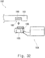
- Patent Literature 1 discloses an aluminum wire 102 composed of a core wire 100 and an insulation coating 101 as shown in Fig. 32 of the present application.
- the insulation coating 101 has a partially peeled part 103 so that the core wire 100 is exposed.
- a terminal 104 has a rib 106 with a rectangular frame shape along the periphery of a swaging part 105, and the rib 106 bites into the insulation coating 101, and thereby the partially peeled part 103 is sealed.
- Patent Literature 1 mentions nothing about sealing a distal end surface of the core wire.
- An object of the present invention is to provide a technique to reliably seal a distal end surface of a core wire as well as preventing a distal end coating part that covers a distal end of the core wire from coming off.
- a wire including a core wire and an insulation coating that covers an outer periphery of the core wire
- the core wire includes a distal end region containing a distal end surface of the core wire, and a body region being a part other than the distal end region
- the distal end region includes a first distal end region containing the distal end surface, and a second distal end region located between the first distal end region and the body region
- the insulation coating includes a distal end coating part that covers an outer periphery of the first distal end region in a tube shape, an insulation coating body that covers an outer periphery of the body region in a tube shape, at least one coating joint part that joins the distal end coating part and the insulation coating body together in such a way that at least part of an outer periphery of the second distal end region is exposed, and a coating extension part that extends from the distal end coating part beyond the distal end surface in a tube shape.
- a thickness of the coating joint part in a radial direction is preferably smaller than a maximum thickness of the insulation coating body in the radial direction.
- the insulation coating body includes a first body part touching the coating joint part, and a second body part located farther from the distal end surface than the first body part is, a thickness of the first body part in the radial direction is the same as the thickness of the coating joint part in the radial direction, and a thickness of the second body part in the radial direction is greater than the thickness of the first body part in the radial direction.
- a welded part having been crushed in a cross direction crossing a longitudinal direction of the wire and closed by welding is formed in the coating extension part.
- a center of gravity of a cross-section of the welded part orthogonal to the longitudinal direction of the wire and a center of gravity of a cross-section of the distal end coating part orthogonal to the longitudinal direction of the wire preferably do not coincide.
- the welded part is preferably formed to avoid a virtual extension line of a central axis of the core wire.
- a cross-sectional shape of the welded part orthogonal to the longitudinal direction of the wire is preferably a track shape, an ellipse, a U-shape, or a V-shape.
- the cross direction is preferably a direction orthogonal to the longitudinal direction of the wire.
- an internal space of the coating extension part is filled with a sealing material, or a sealing member is inserted into the internal space of the coating extension part.
- a wire with a terminal including the above-described wire, and a terminal attached to the wire wherein the terminal includes an electrical contact part capable of coming into electrical contact with a mating terminal, a wire crimp part to be crimped onto the wire, and a terminal joint part that joins the electrical contact part and the wire crimp part together, and the wire crimp part includes two crimp pieces, and each of the crimp pieces is crimped onto the distal end coating part, the second distal end region, and the insulation coating body, and thereby the second distal end region is sealed, or the wire crimp part is formed in a tube shape and crimped onto the distal end coating part, the second distal end region, and the insulation coating body, and thereby the second distal end region is sealed.
- a center of gravity of a cross-section of the welded part orthogonal to the longitudinal direction of the wire is preferably located between a center of gravity of a cross-section of the distal end coating part orthogonal to the longitudinal direction of the wire and the terminal joint part.
- a harness including the above-described wire, and a housing that accommodates the wire with the terminal.
- a wire with a terminal including the above-described wire, and a terminal attached to the wire wherein the terminal includes an electrical contact part capable of coming into electrical contact with a mating terminal, a wire crimp part to be crimped onto the wire, and a terminal joint part that joins the electrical contact part and the wire crimp part together, and the wire crimp part includes two crimp pieces, and each of the crimp pieces is crimped onto the distal end coating part, the second distal end region, and the insulation coating body, and thereby the second distal end region is sealed, or the wire crimp part is formed in a tube shape and crimped onto the distal end coating part, the second distal end region, and the insulation coating body, and thereby the second distal end region is sealed.
- a harness including the above-described wire, and a housing that accommodates the wire with terminal.
- a manufacturing method for a wire including an exposing step of exposing at least part of a core wire by making a hole in an insulation coating that covers the core wire, and a stretching step of stretching the insulation coating in such a way that the insulation coating extends beyond a distal end surface of the core wire.
- the stretching step is performed after the exposing step, and in the stretching step, the insulation coating is stretched in such a way that the hole made in the exposing step is enlarged.
- the exposing step is performed after the stretching step, and in the exposing step, the hole is made in a part having become thinner than before stretching as a result of having been stretched in the stretching step.
- the manufacturing method preferably further includes a slit cutting step of cutting, in the insulation coating, at least two first slits extending in the longitudinal direction of the core wire and separating from each other in a circumferential direction, wherein the stretching step is performed after the slit cutting step, the exposing step is performed after the stretching step, in the stretching step, the insulation coating is stretched in such a way that the at least two first slits cut in the slit cutting step are elongated, and in the exposing step, at least two second slits are cut to connect corresponding ends of the at least two first slits, and thereby the hole is made in the insulation coating.
- the manufacturing method preferably further includes a step of crushing a part of the insulation coating extending beyond the distal end surface of the core wire in a cross direction crossing a longitudinal direction of the core wire, and a step of closing the crushed part by welding.
- the manufacturing method preferably further includes a step of filling a sealing material or inserting a sealing member into an internal space of a part of the insulation coating extending beyond the distal end surface of the core wire.
- a manufacturing method for a wire with a terminal manufacturing the wire with the terminal by attaching the terminal to the wire including a core wire and an insulation coating that covers the core wire, including an exposing step of exposing at least part of the core wire by making a hole in the insulation coating, a stretching step of stretching the insulation coating in such a way that the insulation coating extends beyond a distal end surface of the core wire, a crimping step of crimping a crimp piece of the terminal onto the wire so as to seal a part where the core wire is exposed, and a sealing step of sealing the distal end surface of the core wire by welding a part of the insulation coating extending beyond the distal end surface of the core wire after the crimping step.
- the present invention is able to effectively seal the distal end surface by using the coating extension part as well as preventing the distal end coating part from coming off the core wire.
- a first embodiment is described hereinafter with reference to Figs. 1 to 21 .
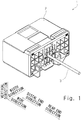
- Fig. 1 is a perspective view of a harness 1.
- the harness 1 includes a housing 2 made of insulating resin and a plurality of wires with terminal 3 to be accommodated in the housing 2.
- Fig. 1 only one wire with terminal 3 among the plurality of wires with terminal 3 is shown, and the other wires with terminal 3 are not shown.
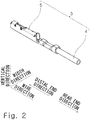
- Fig. 2 is a perspective view of the wire with terminal 3. As shown in Fig. 2 , the wire with terminal 3 includes a wire 4 and a terminal 5 that is attached to the wire 4.
- Fig. 3 is a perspective view of the wire 4 before the terminal 5 is attached thereto.
- Fig. 4 is a front view of the wire 4 before the terminal 5 is attached thereto.
- Fig. 5 is a front cross-sectional view of the wire 4 before the terminal 5 is attached thereto.
- the scale is adjusted for dimensional notation.
- Fig. 6 is a left side view of the wire 4 before the terminal 5 is attached thereto.
- the wire 4 includes a core wire 6 and an insulation coating 7 that covers the outer periphery of the core wire 6.
- the core wire 6 is a stranded wire consisting of a plurality of individual wires twisted together, or an aluminum conductor steel-reinforced cable consisting of hard-drawn aluminum wires twisted together around a galvanized steel wire.
- the material of the individual wires of the stranded wire may be copper, aluminum, or an aluminum alloy, for example.
- the individual wires of the stranded wire may be plated individually.
- the core wire 6 is a stranded wire consisting of a plurality of individual wires made of an aluminum alloy twisted together.
- the core wire 6 includes a distal end region 9 and a body region 10.
- the distal end region 9 is a part including a distal end surface 11 of the core wire 6.
- the body region 10 is a part other than the distal end region 9 of the core wire 6.
- the distal end region 9 and the body region 10 are adjacent to each other in the longitudinal direction of the wire 4.
- the "longitudinal direction of the wire 4" is also referred to simply as "wire direction”.
- the distal end region 9 and the body region 10 are located in this recited order in the direction of drawing away from the distal end surface 11.
- the distal end region 9 is located between the distal end surface 11 and the body region 10 in the wire direction.
- the distal end region 9 includes a first distal end region 12 and a second distal end region 13.
- the first distal end region 12 is a part including the distal end surface 11 of the core wire 6.
- the second distal end region 13 is a part other than the first distal end region 12 of the distal end region 9.
- the first distal end region 12 and the second distal end region 13 are adjacent to each other in the wire direction.
- the first distal end region 12 and the second distal end region 13 are located in this recited order in the direction of drawing away from the distal end surface 11.
- the second distal end region 13 is located between the first distal end region 12 and the body region 10.
- the insulation coating 7 is weldable synthetic resin such as vinyl chloride, for example.
- "Welding” includes heat welding, ultrasonic welding, and laser welding, for example.
- the insulation coating 7 includes a distal end coating part 15, an insulation coating body 16, a coating joint part 17, and a coating extension part 18.
- the coating extension part 18, the distal end coating part 15, the coating joint part 17 and the insulation coating body 16 are located in this recited order in the wire direction.
- the distal end coating part 15 is formed in a tube shape and covers the outer periphery of the first distal end region 12. As shown in Fig. 5 , the distal end coating part 15 has a thickness 15T in the radial direction.
- the insulation coating body 16 is formed in a tube shape and covers the outer periphery of the body region 10.
- the insulation coating body 16 includes a first body part 19 and a second body part 20.
- the first body part 19 and the second body part 20 are adjacent to each other in the wire direction.
- the first body part 19 is located closer to the distal end surface 11 than the second body part 20 is.
- the second body part 20 is located farther from the distal end surface 11 than the first body part 19 is.
- the first body part 19 touches the coating joint part 17 in the wire direction.
- the first body part 19 has a thickness 19T in the radial direction.
- the second body part 20 has a thickness 20T in the radial direction.
- the thickness 20T is greater than the thickness 19T.
- the thickness 20T corresponds to the maximum thickness of the insulation coating body 16.
- the coating joint part 17 is a part that joins the distal end coating part 15 and the insulation coating body 16 together.
- the coating joint part 17 is elongated in the wire direction in such a way that at least part of the outer periphery of the second distal end region 13 is exposed.
- the central angle of the coating joint part 17 is 5 to 60 degrees, preferably 10 to 45 degrees, and more preferably 15 to 30 degrees. As the central angle of the coating joint part 17 is greater, the sealing effect of the coating joint part 17 increases, and as the central angle of the coating joint part 17 is smaller, the contact reliability between the terminal 5 and the core wire 6 increases.
- the distal end coating part 15 and the insulation coating body 16 are joined by one coating joint part 17.
- the distal end coating part 15 and the insulation coating body 16 may be joined by a plurality of coating joint parts 17.
- the coating joint part 17 has a thickness 17T in the radial direction.
- the thickness 17T is smaller than the thickness 20T which corresponds to the maximum thickness of the insulation coating body 16 in the radial direction.
- the thickness 15T, the thickness 17T and the thickness 19T are equal.
- the coating extension part 18 is a part that extends from the distal end coating part 15 beyond the distal end surface 11 in a tube shape.
- the coating extension part 18 is a part that does not cover the core wire 6.
- the coating extension part 18 is a part that projects in a distal end direction from the distal end coating part 15. In one specific example, the projecting length of the coating extension part 18 in the wire direction is greater than the outer diameter of the core wire 6.
- the "distal end direction” is the direction of viewing the distal end surface 11 from the body region 10 in the wire direction.
- a “rear end direction” is the direction of viewing the body region 10 from the distal end surface 11 in the wire direction.
- a welded part 21 is formed in the coating extension part 18.
- the welded part 21 is a tube that is crushed in a vertical direction orthogonal to the wire direction, and it is a part where the internal space of the tube-shaped coating extension part 18 is closed by welding.
- the welded part 21 extends linearly in the wire direction.
- the cross-sectional shape of the welded part 21 orthogonal to the wire direction is a track shape that is asymmetric with respect to a central axis 6C of the core wire 6 and symmetric in a width direction.
- Fig. 6 shows a center of gravity 21G of the cross-section of the welded part 21 and a center of gravity 15G of the cross-section of the distal end coating part 15 orthogonal to the wire direction. As shown in Fig.
- the center of gravity 21G of the cross-section of the welded part 21 and the center of gravity 15G of the cross-section of the distal end coating part 15 do not coincide.
- the welded part 21 is formed to avoid a virtual extension line 6D of the central axis 6C of the core wire 6.
- a linear weld scar 22 is left on a distal end surface 21A of the welded part 21.
- the weld scar 22 is left as a result of closing the internal space of the tube-shaped coating extension part 18 by welding, and therefore the weld scar 22 extends in a single linear line.
- Fig. 7 is a perspective view of the terminal 5 before being attached to the wire 4.
- Fig. 8 is a partially cutaway perspective view of the terminal 5 before being attached to the wire 4.
- Fig. 9 is a front view of the terminal 5 before being attached to the wire 4.
- the terminal 5 includes a wire crimp part 25, a terminal joint part 26, and an electrical contact part 27.
- the wire crimp part 25, the terminal joint part 26, and the electrical contact part 27 are continuously formed in this recited order in the distal end direction.
- the terminal joint part 26 joins the wire crimp part 25 and the electrical contact part 27 together.
- the wire crimp part 25 is a part to be crimped onto the wire 4. As shown in Fig. 7 , the wire crimp part 25 is formed in an open barrel shape in this embodiment. Specifically, the wire crimp part 25 includes a bottom plate part 28 and two crimp pieces 29. As shown in Fig. 8 , the thickness direction of the bottom plate part 28 is substantially parallel to the vertical direction. The two crimp pieces 29 extend upward from the end of the bottom plate part 28 in the width direction. Thus, when viewing the electrical contact part 27 from the wire crimp part 25 in the wire direction, the wire crimp part 25 has a U-shape that opens upward.
- each of the distal end serration 31 and the rear end serration 33 is in the form of a straight gash that extends linearly in the direction orthogonal to the wire direction.
- the center serration 32 is in the form of a plurality of recesses arranged in a matrix.
- the electrical contact part 27 is a part that is capable of coming into electrical contact with a mating terminal, which is not shown.
- the electrical contact part 27 includes a contact spring piece 35 and a spring protector 36 that accommodates and protects the contact spring piece 35.
- the spring protector 36 is a rectangular tube that extends in the wire direction.
- the spring protector 36 includes a bottom plate part 37, two side plate parts 38, and a top plate part 39 that is opposed to the bottom plate part 37.
- the bottom plate part 37 and the top plate part 39 are opposed to each other in the vertical direction.
- the top plate part 39 is disposed above the bottom plate part 37.
- the two side plate parts 38 are opposed to each other in the width direction.
- a length 39D from a distal end 36A of the spring protector 36 to a rear end 39B of the top plate part 39 is smaller than a length 38D from the distal end 36A of the spring protector 36 to a rear end 38B of the two side plate parts 38.
- the top plate part 39 can be regarded as being cut away in close proximity to a rear end 36B of the spring protector 36. Note that the rear end 38B of the two side plate parts 38 shown in Fig. 9 is capable of coming into contact with a retainer, which is described later, in the wire direction.
- the contact spring piece 35 is accommodated in the rectangular tubular spring protector 36 and thereby protected by the spring protector 36.
- the contact spring piece 35 is elongated in the wire direction.
- the contact spring piece 35 is supported like a cantilever beam by the spring protector 36.
- the terminal joint part 26 is a part that joins the wire crimp part 25 and the electrical contact part 27 together.
- the terminal joint part 26 includes a bottom plate part 45 and two side plate parts 46.
- the thickness direction of the bottom plate part 45 is substantially parallel to the vertical direction.
- the two side plate parts 46 extend upward from the end of the bottom plate part 45 in the width direction.
- the bottom plate part 45 joins the bottom plate part 28 of the wire crimp part 25 and the bottom plate part 37 of the spring protector 36 of the electrical contact part 27 together in the wire direction.
- each side plate part 46 joins each crimp piece 29 of the wire crimp part 25 and each side plate part 38 of the electrical contact part 27 together in the wire direction.
- the terminal 5 described above is produced by plating with a base metal, such as tin, nickel or zinc, a single thin plate made of copper or a copper alloy and then pressing it, for example.
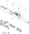
- Fig. 10 is a perspective view of the terminal 4 and the wire 5 immediately before the terminal 4 is crimped onto the wire 5.
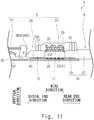
- Fig. 11 is a front cross-sectional view of the terminal 4 and the wire 5 immediately before the terminal 4 is crimped onto the wire 5.
- Fig. 12 is a perspective view of the terminal 4 and the wire 5 after the terminal 4 is crimped onto the wire 5.
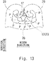
- Figs. 13 and 14 are cross-sectional views along line XIII-XIII of Fig. 12 .
- Fig. 15 is a partial front view of the terminal 4 and the wire 5 after the terminal 4 is crimped onto the wire 5.
- Fig. 16 shows another specific example of a cross-sectional view along line XVI-XVI of Fig. 12 .
- the wire 4 is first disposed between the two crimp pieces 29 of the wire crimp part 25.
- the wire 4 is disposed between the two crimp pieces 29 of the wire crimp part 25 so as to satisfy the following conditions.
- the two crimp pieces 29 of the wire crimp part 25 of the terminal 5 are crimped to the wire 4 as shown in Fig. 12 by using a dedicated crimp tool.
- each crimp piece 29 is crimped to the distal end coating part 15 shown in Fig. 11 , the coating joint part 17 and the core wire exposure part 23, and the first body part 19.
- the two crimp pieces 29 are plastically deformed inward in such a way that the two crimp pieces 29 come into close contact with each other and the two crimp pieces 29 are bent to be convex inward.
- Figs. 13 and 14 show a plurality of individual wires P that constitute the core wire 6.
- no hatching is shown on the cross-section of the terminal 5 and the wire 6 for the convenience of description.
- the coating joint part 17 is crushed in the width direction between the two crimp pieces 29, so that the coating joint part 17 contributes airtightness between the two crimp pieces 29.
- the area of contact between the two crimp pieces 29 is relatively small, and the coating joint part 17 stretches in the vertical direction between the two crimp pieces 29.
- Fig. 13 the specific example shown in Fig.
- the area of contact between the two crimp pieces 29 is relatively large, and the coating joint part 17 is deformed into a substantially equilateral triangle between the two crimp pieces 29.
- the cross-sectional area of the coating joint part 17 is small in this embodiment, the coating joint part 17 is not spread out in the width direction at the time of crimping, and therefore inhibition of electrical contact between the individual wires P that constitute the core wire 6 and each crimp piece 29 does not occur.
- the second distal end region 13 is more reliably sealed than in the specific example shown in Fig. 14 .
- the coating joint part 17 is crushed in the width direction by the two crimp pieces 29, and therefore the airtightness between the two crimp pieces 29 is improved.
- the specific example shown in Fig. 14 when the two crimp pieces 29 spring back, there is a possibility that a gap occurs in the vicinity of the coating joint part 17, such as between a point of contact between the two crimp pieces 29 and the coating joint part 17.
- a gap occurs in the vicinity of the coating joint part 17, such as between a point of contact between the two crimp pieces 29 and the coating joint part 17.
- the sealing of the second distal end region 13, which is, the waterproof capability of the second distal end region 13 that, in the state where the terminal 5 is crimped onto the wire 4, the two crimp pieces 29 are not in direct contact with each other, and the coating joint part 17 is interposed between the two crimp pieces 29 in the width direction in such a way that the two crimp pieces 29 compress the coating joint part 17 in the width direction.
- the distal end coating part 15 bites into the distal end serration 31 of each crimp piece 29 shown in Fig. 11 , and also the first body part 19 bites into the rear end serration 33 of each crimp piece 29, and consequently the core wire exposure part 23 is successfully sealed by the wire crimp part 25, the distal end coating part 15 and the first body part 19. Further, the center serration 32 bites into the core wire exposure part 23, and consequently a passivation film of the core wire 6 is locally removed, which establishes good continuity of the terminal 5 and the core wire 6. Note that the distal end surface 11 of the core wire 6 is sealed as a result that the welded part 21 is formed in the coating extension part 18.
- the core wire 6 is located above the terminal joint part 26 between the electrical contact part 27 and the wire crimp part 25. Specifically, in this embodiment, at least part of the core wire 6 is located above an upper end 46C of the two side plate parts 46 of the terminal joint part 26 between the electrical contact part 27 and the wire crimp part 25. In other words, at least part of the core wire 6 is farther from the bottom plate part 45 than the upper end 46C is. This enables confirmation as to whether the distal end surface 11 of the core wire 6 is located between the electrical contact part 27 and the wire crimp part 25 after crimping by applying an X-ray to the wire with terminal 3 in the width direction. Instead of an X-ray, an ultrasonic wave may be used.
- the center of gravity 21G of the cross-section of the welded part 21 is located between the center of gravity 15G of the cross-section of the distal end coating part 15 and the bottom plate part 45 of the terminal joint part 26 in the vertical direction.
- the retainer insertion space 47 into which a retainer, which is described later, is inserted is effectively provided between the electrical contact part 27 and the wire crimp part 25.
- Fig. 17 is a partially cutaway perspective view of the harness 1.
- Fig. 18 is a partial front cross-sectional view of the harness 1.
- the housing 2 includes a housing body 51 having a plurality of cavities 50 into which the wire with terminal 3 is able to be inserted in the wire direction, and a retainer 52 for secondary locking.
- the retainer 52 is held to be vertically movable with respect to the housing body 51.
- the retainer 52 is located opposite to the rear end 36B of the spring protector 36 of the wire with terminal 3 in the wire direction and thereby controls the detachment of the wire with terminal 3 in the rear end direction.
- the retainer 52 has a locking lance 53 that is able to be inserted into the retainer insertion space 47 of the wire with terminal 3. Then, as shown in Fig. 18 , when the retainer 52 is pulled down, the locking lance 53 is inserted into the retainer insertion space 47 of the wire with terminal 3, and the locking lance 53 thereby becomes capable of coming into contact with the rear end 36B of the spring protector 36 in the wire direction. In other words, when the retainer 52 is pulled down, the locking lance 53 becomes capable of coming into contact with the rear end 38B of each side plate part 38 of the spring protector 36 shown in Fig. 9 . Thus, even when the wire with terminal 3 is tried to pull out of the housing 2, the rear end 36B of the spring protector 36 catches on the locking lance 53, thereby prohibiting the wire with terminal 3 from being pulled out of the housing 2.
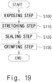
- FIG. 19 is a flowchart of a manufacturing method for the wire with terminal 3.
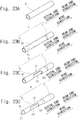
- Figs. 20A to 20C are views illustrating each step of the manufacturing method for the wire with terminal 3.
- Fig. 21 is a perspective view of a processing jig.
- Step S100 Exposing Step
- a method of partly removing the insulation coating 7 may be (1) a method including a step of cutting a slit in the insulation coating 7 with a cutting tool, (2) a method including a step of cutting a slit in the insulation coating 7 by laser processing, (3) a method including a step of partly evaporating the insulation coating 7 by laser processing, and so on.
- Step S110 Stretching Step
- the insulation coating 7 is stretched in the distal end direction in such a way that the insulation coating 7 extends beyond the distal end surface 11.
- the insulation coating 7 is stretched in the distal end direction in such a way that the opening area of the core wire exposure hole 60 made in Step S100 is enlarged.
- the insulation coating 7 is stretched in the distal end direction in such a way that the coating joint part 17 formed in Step S100 becomes thinner than that before stretching. It is preferred to use a processing jig 61 shown in Fig. 21 in order to stretch the insulation coating 7 without splitting it.
- the processing jig 61 includes an upper jig 62 and a lower jig 63.
- the wire 4 is sandwiched between the upper jig 62 and the lower jig 63, and then the processing jig 61 is moved in the distal end direction while the wire 4 is heated indirectly through the upper jig 62 and the lower jig 63.
- the coating extension part 18, which is a part of the insulation coating 7 extending beyond the distal end surface 11 in the distal end direction, is formed.
- the coating extension part 18 is crushed in the vertical direction, and the crushed part is closed by welding, and thereby the welded part 21 is formed in the coating extension part 18.
- the distal end surface 11 is thereby sealed.
- the step of crushing and the step of closing by welding may be performed simultaneously.
- Step S130 Crimping Step
- the terminal 5 is crimped onto the wire 4.
- the wire with terminal 3 is thereby produced.
- the first embodiment is described above.
- the above-described first embodiment has the following features.
- the wire 4 includes the core wire 6 and the insulation coating 7 that covers the outer periphery of the core wire 6.
- the core wire 6 includes the distal end region 9 containing the distal end surface 11 of the core wire 6, and the body region 10, which is a part other than the distal end region 9.
- the distal end region 9 includes the first distal end region 12 containing the distal end surface 11, and the second distal end region 13 located between the first distal end region 12 and the body region 10.
- the insulation coating 7 includes the distal end coating part 15 that covers the outer periphery of the first distal end region 12 in a tube shape, the insulation coating body 16 that covers the outer periphery of the body region 10 in a tube shape, the coating joint part 17 that joins the distal end coating part 15 and the insulation coating body 16 together in such a way that at least part of the outer periphery of the second distal end region 13 is exposed, and the coating extension part 18 that extends from the distal end coating part 15 beyond the distal end surface 11 in a tube shape.
- This structure is capable of effectively sealing the distal end surface 11 by using the coating extension part 18 as well as preventing the distal end coating part 15 from coming off the core wire 6 by the presence of the coating joint part 17.
- the thickness 17T of the coating joint part 17 in the radial direction is smaller than the thickness 20T which corresponds to the maximum thickness of the insulation coating body 16 in the radial direction.
- the cross-section of the coating joint part 17 is small as shown in Figs. 13 and 14 , and therefore the coating joint part 17 is not easily spread out in the width direction. The degree of inhibiting contact between the second distal end region 13 and the wire 5 is thereby reduced, which improves the contact reliability between the second distal end region 13 and the wire 5.
- the insulation coating body 16 includes the first body part 19 that touches the coating joint part 17, and the second body part 20 that is farther from the distal end surface 11 than the first body part 19 is.
- the thickness 19T of the first body part 19 in the radial direction is the same as the thickness 17T of the coating joint part 17 in the radial direction.
- the thickness 20T of the second body part 20 in the radial direction is greater than the thickness 19T of the first body part 19 in the radial direction.
- a difference between the outer diameter of the second distal end region 13 and the outer diameter of the first body part 19 is small, and accordingly a difference in level between the second distal end region 13 and the first body part 19 is small, which improves airtightness between the second distal end region 13 and the terminal 5.
- the welded part 21 that is crushed in the vertical direction (a cross direction crossing the longitudinal direction of the wire 4) and closed by welding is formed in the coating extension part 18.
- the distal end surface 11 is reliably sealed.
- the center of gravity 21G of the cross-section of the welded part 21 orthogonal to the wire direction and the center of gravity 15G of the cross-section of the distal end coating part 15 orthogonal to the wire direction do not coincide.
- the current position of the coating joint part 17 in the circumferential direction is identifiable by detecting the current position of the welded part 21 in the circumferential direction. If the current position of the coating joint part 17 in the circumferential direction is identifiable, the position of the coating joint part 17 in the circumferential direction is freely adjustable when crimping the terminal 5 onto the wire 4.
- the center of gravity 21G of the cross-section of the welded part 21 orthogonal to the wire direction and the center of gravity 15G of the cross-section of the distal end coating part 15 orthogonal to the wire direction do not coincide.
- the current position of the welded part 21 in the circumferential direction is easily recognizable based on the position of the coating joint part 17 in the circumferential direction.
- the welded part 21 is formed to avoid the virtual extension line 6D of the central axis 6C of the core wire 6.
- the retainer insertion space 47 shown in Fig. 15 is effectively provided.
- the cross-sectional shape of the welded part 21 orthogonal to the wire direction is a track shape. This structure allows a welding jig of the welded part 21 to have a simple structure.
- the direction of crushing the coating extension part 18 is preferably the vertical direction orthogonal to the wire direction. Note that, however, the coating extension part 18 may be crushed in the direction obliquely intersecting the wire direction.
- the wire with terminal 3 includes the above-described wire 4, and the terminal 5 attached to the wire 4.
- the terminal 5 includes the electrical contact part 27 that is capable of coming into electrical contact with a mating terminal, the wire crimp part 25 to be crimped onto the wire 4, and the terminal joint part 26 that joins the electrical contact part 27 and the wire crimp part 25 together.
- the wire crimp part 25 includes two crimp pieces 29. As shown in Fig. 11 , each crimp piece 29 is crimped onto the distal end coating part 15, the core wire exposure part 23 (the second distal end region 13) and the insulation coating body 16, and thereby the core wire exposure part 23 (the second distal end region 13) is sealed.
- the center of gravity 21G of the cross-section of the welded part 21 orthogonal to the longitudinal direction of the wire 4 is located between the center of gravity 15G of the cross-section of the distal end coating part 15 orthogonal to the longitudinal direction of the wire 4 and the terminal joint part 26.
- the retainer insertion space 47 is effectively provided.
- the harness 1 includes the wire with terminal 3, and the housing 2 that accommodates the wire with terminal 3.
- the housing 2 includes the retainer 52 that is capable of coming into contact with the rear end 36B of the spring protector 36 of the electrical contact part 27 in the wire direction.
- a manufacturing method for the wire 4 includes the exposing step (S100) of exposing at least part of the core wire 6 by making the core wire exposure hole 60 (hole) in the insulation coating 7 that covers the core wire 6, and the stretching step (S110) of stretching the insulation coating 7 in such a way that the insulation coating 7 extends beyond the distal end surface 11 of the core wire 6.
- This method is capable of forming the coating extension part 18 suitable for sealing the distal end surface 11 of the core wire 6 as well as preventing the distal end coating part 15 from coming off the core wire 6.
- the stretching step (S110) is performed after the exposing step (S100).
- the insulation coating 7 is stretched in such a way that the opening area of the core wire exposure hole 60 made in the exposing step (S100) is enlarged. This method is capable of making the coating joint part 17 thinner than that before stretching
- the manufacturing method for the wire 4 further includes the step (S120) of crushing the coating extension part 18, which is a part of the insulation coating 7 extending beyond the distal end surface 11 of the core wire 6, in the cross direction crossing the longitudinal direction of the core wire 6, and the step (S120) of closing the crushed part by welding.
- This method is capable of sealing the distal end surface 11 at low cost.
- FIG. 22 is a flowchart of a manufacturing method for the wire with terminal 3.
- Figs. 23A to 23D are views illustrating each step of the manufacturing method for the wire with terminal 3.
- This embodiment is different from the above-described first embodiment in the manufacturing method for the wire with terminal 3.
- the exposing step (S100) is performed first, and the stretching step (S110) is performed after that.
- a stretching step (S200) is performed first, and an exposing step (S210) is performed after that.
- Step S200 Stretching Step
- the insulation coating 7 is stretched in the distal end direction in such a way that the insulation coating 7 extends beyond the distal end surface 11.
- the coating extension part 18, which is a part of the insulation coating 7 extending beyond the distal end surface 11, is formed.
- Step S210 Exposing Step
- the insulation coating 7 is cut at a position toward the rear end direction relative to the distal end surface 11 of the core wire 6, and thereby the core wire exposure hole 60 is made in the insulation coating 7.
- the core wire exposure hole 60 is made in a part that has become thinner than before stretching as a result of having been stretched in the stretching step (S200).
- the coating joint part 17 is thereby formed, and the core wire exposure part 23 is also made.
- Step S220 Sealing Step
- the coating extension part 18 is crushed in the vertical direction, and the crushed part is closed by welding, and thereby the welded part 21 is formed in the coating extension part 18.
- the distal end surface 11 is thereby sealed.
- Step S230 Crimping Step
- the terminal 5 is crimped onto the wire 4.
- the wire with terminal 3 is thereby produced.
- the stretching step and the exposing step may be interchanged.
- the exposing step is performed after the stretching step, and, in the exposing step (S210), the core wire exposure hole 60 is made in a part that has become thinner than before stretching as a result of having been stretched in the stretching step (S200).
- This method is capable of making the coating joint part 17 thin in a simple process.
- FIG. 24 is a flowchart of a manufacturing method for the wire with terminal 3.
- Figs. 25A to 25D are views illustrating each step of the manufacturing method for the wire with terminal 3.
- This embodiment is different from the above-described first embodiment in the manufacturing method for the wire with terminal 3.
- the exposing step (S100) is performed first, and the stretching step (S110) is performed after that.
- this embodiment is as follows.
- Step S300 Slit Cutting Step
- two first slits 65 that extend in the wire direction and separate from each other in the circumferential direction are cut in the insulation coating 7 that covers the core wire 6.
- the two first slits 65 are cut at the positions away from the distal end surface 11 in the wire direction.
- the two first slits 65 can be cut with a cutting tool, for example.
- Step S310 Stretching Step
- the insulation coating 7 is stretched in the distal end direction in such a way that the insulation coating 7 extends beyond the distal end surface 11.
- the insulation coating 7 is stretched in such a way that the length of the two first slits 65 cut in the slit cutting step (S300) in the wire direction is elongated.
- Step S320 Exposing Step
- two second slits 66 are cut to connect the corresponding ends of the two first slits 65, and thereby the core wire exposure hole 60 is made in the insulation coating 7.
- the coating joint part 17 is thereby formed, and the core wire exposure part 23 is also made.
- the coating extension part 18 is crushed in the vertical direction, and the crushed part is closed by welding, and thereby the welded part 21 is formed in the coating extension part 18.
- the distal end surface 11 is thereby sealed.
- Step S340 Crimping Step
- the terminal 5 is crimped onto the wire 4.
- the wire with terminal 3 is thereby produced.
- the above-described third embodiment has the following features.
- the manufacturing method for the wire 4 further includes the slit cutting step (S300) of cutting, in the insulation coating 7 of the wire 4, the two first slits 65 extending in the longitudinal direction of the core wire 6 and separating from each other in the circumferential direction.
- the stretching step (S3 10) is performed after the slit cutting step (S300).
- the exposing step (S320) is performed after the stretching step (S310).
- the insulation coating 7 is stretched in such a way that the length of the two first slits 65 cut in the slit cutting step (S300) in the wire direction is elongated.
- the two second slits 66 are cut to connect the corresponding ends of the two first slits 65, and thereby the core wire exposure hole 60 is made in the insulation coating 7.
- This method is capable of making the coating joint part 17 thin in a simple process. Further, this method is capable of making the core wire exposure hole 60 in two separate steps.
- the method may cut three or more first slits 65 instead of cutting the two first slits 65.
- the method may cut three or more second slits 66 instead of cutting the two second slits 66.
- FIG. 26 is an enlarged perspective view of the coating extension part 18.
- the cross-sectional shape of the welded part 21 is a track shape as shown in Fig. 6 .
- the cross-sectional shape of the welded part 21 is a U-shape that is convex outward in the radial direction.
- the welded part 21 is formed to avoid the virtual extension line 6D.
- the cross-sectional shape of the welded part 21 may be a V-shape or an ellipse instead of a U-shape.
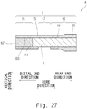
- FIG. 27 is a partial front cross-sectional view of the wire 4.
- the distal end surface 11 of the core wire 6 is sealed by forming the welded part 21 in the coating extension part 18.
- the distal end surface 11 of the core wire 6 is sealed by filling an internal space 18S of the coating extension part 18 with the sealing material 67.
- the sealing material 67 may be an adhesive or a water repellant. Compared with the case of simply applying the sealing material 67 onto the distal end surface 11 of the core wire 6, filling the internal space 18S of the coating extension part 18 with the sealing material 67 is expected to have a storage effect to maintain the state where the sealing material 67 is in contact with the distal end surface 11 of the core wire 6 without coming off the distal end surface 11 of the core wire 6 due to dripping before the sealing material 67 is hardened.
- the sealing material 67 is hardened, this is expected to have an effect of adjusting the position of the coating extension part 18 of the core wire 6 in relation to the terminal 5 as desired at the time of crimping because the outer shape of the hardened sealing material 67 does not vary. Further, since the hardened sealing material 67 is covered with the coating extension part 18, this is also expected to have an effect of preventing the sealing material 67 from coming off the wire 4.
- the distal end surface 11 of the core wire 6 may be sealed by inserting a hard or soft sealing member into the internal space 18S of the coating extension part 18 instead of filling the internal space 18S of the coating extension part 18 with the sealing material 67.
- the hard sealing member may be acrylic resin or polystyrene, for example.
- the soft sealing member may be polyethylene or polypropylene, for example.
- FIG. 28 is a partial perspective view of the wire with terminal.
- the electrical contact part 27 is shown in a simplified way.
- the wire crimp part 25 of the terminal 5 is formed in an open barrel shape as shown in Fig. 10 .
- the wire crimp part 25 of the terminal 5 is formed in a tubular closed barrel shape as shown in Fig. 28 . Then, the wire crimp part 25 is crimped onto the distal end coating part 15, the core wire exposure part 23 (the second distal end region 13) and the insulation coating body 16 just like in the first embodiment, and thereby the core wire exposure part 23 (the second distal end region 13) is sealed.
- the first to sixth embodiments are described above.
- the above-described first to sixth embodiments may be implemented in any combination.
- a modified example of the first to sixth embodiments is described hereinbelow as a modified example 1 with reference to Fig. 29 .
- differences of this modified example from each of the above-described embodiments are mainly described, and redundant description is omitted.
- the stretching step (S110) of Fig. 19 only the coating joint part 17 of the insulation coating 7 may be stretched in the wire direction as shown in Fig. 29 . In this case, only the coating joint part 17 is thin compared with the other parts of the insulation coating 7.
- a modified example of the first to fourth embodiments and the sixth embodiment is described hereinbelow as a modified example 2 with reference to Figs. 30 and 31 .
- differences of this modified example from each of the above-described embodiments are mainly described, and redundant description is omitted.
- the welded part 21 is first formed in the coating extension part 18 and the distal end surface 11 of the core wire 6 is thereby sealed (S120) by crushing the coating extension part 18 in the vertical direction and then closing the crushed part by welding, and then the terminal 4 is crimped onto the wire 5 (S130).
- the insulation coating 7 is pushed out beyond the wire crimp part 25 in the distal end direction and bulges upward, and thereby the retainer insertion space 47 of the wire with terminal 3 shown in Fig. 18 disappears, which makes it unable to pull the retainer 52 down to a specified locking position.
- the terminal 4 is first crimped onto the wire 5 (crimping step: S420), and then the welded part 21 is formed in the coating extension part 18 and the distal end surface 11 of the core wire 6 is thereby sealed (sealing step: S430) by crushing the coating extension part 18 in the vertical direction and then closing the crushed part by welding.
- an exposing step (S400) and a stretching step (S410) are respectively the same as the exposing step (S100) and the stretching step (S110) in Fig. 19 and therefore not redundantly described. Note that, as described earlier, the exposing step (S400) and the stretching step (S410) may be interchanged.
- Fig. 31 is a view showing the way the welded part 21 is formed in the coating extension part 18 after the terminal 4 is crimped onto the wire 5.
- a welding tool 70 is made to form the welded part 21 in the coating extension part 18 by using heat or ultrasonic waves, for example.
- the second modified example is described above with reference to Figs. 30 and 31 .
- the above-described second modified example has the following features.
- the manufacturing method for the wire with terminal 3 that manufactures the wire with terminal 3 by attaching the terminal 5 to the wire 4 that includes the core wire 6 and the insulation coating 7 covering the core wire 6 as shown in Figs. 2 and 3 includes the exposing step (S400), the stretching step (S410), the crimping step (S420) and the sealing step (S430) as shown in Fig. 30 .
- the exposing step (S400) at least part of the core wire 6 is exposed by making the core wire exposure hole 60 (hole) in the insulation coating 7 as shown in Fig. 20A , for example.
- the insulation coating 7 is stretched in such a way that the insulation coating 7 extends beyond the distal end surface 11 of the core wire 6 as shown in Fig. 20B , for example.
- the crimp piece 29 of the terminal 5 is crimped onto the wire 4 so as to seal the core wire exposure part 23 where the core wire 6 is exposed as shown in Figs. 10 to 12 , for example.
- the sealing step (S430) is performed after the crimping step (S420).
- the distal end surface 11 of the core wire 6 is sealed by welding the coating extension part 18, which is a part of the insulation coating 7 extending beyond the distal end surface 11 of the core wire 6, as shown in Fig. 31 , for example.
- the welded part 21 is formed after crimping, and therefore the retainer insertion space 47 is reliably left above the welded part 21. This allows the retainer 52 to be reliably pulled down to a specified locking position.
Landscapes
- Engineering & Computer Science (AREA)
- Manufacturing & Machinery (AREA)
- Connections Effected By Soldering, Adhesion, Or Permanent Deformation (AREA)
- Manufacturing Of Electrical Connectors (AREA)
- Insulated Conductors (AREA)
Abstract
Description
- The present invention relates to a wire, a wire with terminal, a harness, a manufacturing method for a wire, and a manufacturing method for a wire with a terminal.
-
Patent Literature 1 discloses analuminum wire 102 composed of acore wire 100 and aninsulation coating 101 as shown inFig. 32 of the present application. Theinsulation coating 101 has a partially peeledpart 103 so that thecore wire 100 is exposed. Aterminal 104 has arib 106 with a rectangular frame shape along the periphery of aswaging part 105, and therib 106 bites into theinsulation coating 101, and thereby the partiallypeeled part 103 is sealed. - PTL1: Japanese Unexamined Patent Application Publication No.
2015-115308 - However,
Patent Literature 1 mentions nothing about sealing a distal end surface of the core wire. - An object of the present invention is to provide a technique to reliably seal a distal end surface of a core wire as well as preventing a distal end coating part that covers a distal end of the core wire from coming off.
- According to a first aspect of the present invention, there is provided a wire including a core wire and an insulation coating that covers an outer periphery of the core wire, wherein the core wire includes a distal end region containing a distal end surface of the core wire, and a body region being a part other than the distal end region, the distal end region includes a first distal end region containing the distal end surface, and a second distal end region located between the first distal end region and the body region, and the insulation coating includes a distal end coating part that covers an outer periphery of the first distal end region in a tube shape, an insulation coating body that covers an outer periphery of the body region in a tube shape, at least one coating joint part that joins the distal end coating part and the insulation coating body together in such a way that at least part of an outer periphery of the second distal end region is exposed, and a coating extension part that extends from the distal end coating part beyond the distal end surface in a tube shape.
- A thickness of the coating joint part in a radial direction is preferably smaller than a maximum thickness of the insulation coating body in the radial direction.
- Preferably, the insulation coating body includes a first body part touching the coating joint part, and a second body part located farther from the distal end surface than the first body part is, a thickness of the first body part in the radial direction is the same as the thickness of the coating joint part in the radial direction, and a thickness of the second body part in the radial direction is greater than the thickness of the first body part in the radial direction.
- Preferably, a welded part having been crushed in a cross direction crossing a longitudinal direction of the wire and closed by welding is formed in the coating extension part.
- When viewing in the longitudinal direction of the wire, a center of gravity of a cross-section of the welded part orthogonal to the longitudinal direction of the wire and a center of gravity of a cross-section of the distal end coating part orthogonal to the longitudinal direction of the wire preferably do not coincide.
- The welded part is preferably formed to avoid a virtual extension line of a central axis of the core wire.
- A cross-sectional shape of the welded part orthogonal to the longitudinal direction of the wire is preferably a track shape, an ellipse, a U-shape, or a V-shape.
- The cross direction is preferably a direction orthogonal to the longitudinal direction of the wire.
- Preferably, an internal space of the coating extension part is filled with a sealing material, or a sealing member is inserted into the internal space of the coating extension part.
- Preferably, there is provided a wire with a terminal including the above-described wire, and a terminal attached to the wire, wherein the terminal includes an electrical contact part capable of coming into electrical contact with a mating terminal, a wire crimp part to be crimped onto the wire, and a terminal joint part that joins the electrical contact part and the wire crimp part together, and the wire crimp part includes two crimp pieces, and each of the crimp pieces is crimped onto the distal end coating part, the second distal end region, and the insulation coating body, and thereby the second distal end region is sealed, or the wire crimp part is formed in a tube shape and crimped onto the distal end coating part, the second distal end region, and the insulation coating body, and thereby the second distal end region is sealed.
- When viewing the wire crimp part from the electrical contact part in the longitudinal direction of the wire, a center of gravity of a cross-section of the welded part orthogonal to the longitudinal direction of the wire is preferably located between a center of gravity of a cross-section of the distal end coating part orthogonal to the longitudinal direction of the wire and the terminal joint part.
- Preferably, there is provided a harness including the above-described wire, and a housing that accommodates the wire with the terminal.
- Preferably, there is provided a wire with a terminal including the above-described wire, and a terminal attached to the wire, wherein the terminal includes an electrical contact part capable of coming into electrical contact with a mating terminal, a wire crimp part to be crimped onto the wire, and a terminal joint part that joins the electrical contact part and the wire crimp part together, and the wire crimp part includes two crimp pieces, and each of the crimp pieces is crimped onto the distal end coating part, the second distal end region, and the insulation coating body, and thereby the second distal end region is sealed, or the wire crimp part is formed in a tube shape and crimped onto the distal end coating part, the second distal end region, and the insulation coating body, and thereby the second distal end region is sealed.
- Preferably, there is provided a harness including the above-described wire, and a housing that accommodates the wire with terminal.
- According to a second aspect of the present invention, there is provided a manufacturing method for a wire, including an exposing step of exposing at least part of a core wire by making a hole in an insulation coating that covers the core wire, and a stretching step of stretching the insulation coating in such a way that the insulation coating extends beyond a distal end surface of the core wire.
- Preferably, the stretching step is performed after the exposing step, and in the stretching step, the insulation coating is stretched in such a way that the hole made in the exposing step is enlarged.
- Preferably, the exposing step is performed after the stretching step, and in the exposing step, the hole is made in a part having become thinner than before stretching as a result of having been stretched in the stretching step.
- The manufacturing method preferably further includes a slit cutting step of cutting, in the insulation coating, at least two first slits extending in the longitudinal direction of the core wire and separating from each other in a circumferential direction, wherein the stretching step is performed after the slit cutting step, the exposing step is performed after the stretching step, in the stretching step, the insulation coating is stretched in such a way that the at least two first slits cut in the slit cutting step are elongated, and in the exposing step, at least two second slits are cut to connect corresponding ends of the at least two first slits, and thereby the hole is made in the insulation coating.
- The manufacturing method preferably further includes a step of crushing a part of the insulation coating extending beyond the distal end surface of the core wire in a cross direction crossing a longitudinal direction of the core wire, and a step of closing the crushed part by welding.
- The manufacturing method preferably further includes a step of filling a sealing material or inserting a sealing member into an internal space of a part of the insulation coating extending beyond the distal end surface of the core wire.
- According to a third aspect of the present invention, there is provided a manufacturing method for a wire with a terminal, the method manufacturing the wire with the terminal by attaching the terminal to the wire including a core wire and an insulation coating that covers the core wire, including an exposing step of exposing at least part of the core wire by making a hole in the insulation coating, a stretching step of stretching the insulation coating in such a way that the insulation coating extends beyond a distal end surface of the core wire, a crimping step of crimping a crimp piece of the terminal onto the wire so as to seal a part where the core wire is exposed, and a sealing step of sealing the distal end surface of the core wire by welding a part of the insulation coating extending beyond the distal end surface of the core wire after the crimping step.
- According to the present invention, it is able to effectively seal the distal end surface by using the coating extension part as well as preventing the distal end coating part from coming off the core wire.
-
-
Fig. 1 is a perspective view of a harness (first embodiment). -
Fig. 2 is a perspective view of a wire with a terminal (first embodiment). -
Fig. 3 is a perspective view of a wire before a terminal is attached (first embodiment). -
Fig. 4 is a front view of the wire before the terminal is attached thereto (first embodiment). -
Fig. 5 is a front cross-sectional view of the wire before the terminal is attached thereto (first embodiment). -
Fig. 6 is a left side view of the wire before the terminal is attached thereto (first embodiment). -
Fig. 7 is a perspective view of the terminal before being attached to the wire (first embodiment). -
Fig. 8 is a partially cutaway perspective view of the terminal before being attached to the wire (first embodiment). -
Fig. 9 is a front view of the terminal before being attached to the wire (first embodiment). -
Fig. 10 is a perspective view of the terminal and the wire immediately before the terminal is crimped onto the wire (first embodiment). -
Fig. 11 is a front cross-sectional view of the terminal and the wire immediately before the terminal is crimped onto the wire (first embodiment). -
Fig. 12 is a perspective view of the terminal and the wire after the terminal is crimped onto the wire (first embodiment). -
Fig. 13 is a cross-sectional view along line XIII-XIII ofFig. 12 (first embodiment). -
Fig. 14 is a cross-sectional view along line XIII-XIII ofFig. 12 (first embodiment). -
Fig. 15 is a partial front view of the terminal and the wire after the terminal is crimped onto the wire (first embodiment). -
Fig. 16 is a cross-sectional view along line XVI-XVI ofFig. 12 (first embodiment). -
Fig. 17 is a partially cutaway perspective view of the harness (first embodiment). -
Fig. 18 is a partial front cross-sectional view of the harness (first embodiment). -
Fig. 19 is a flowchart of a manufacturing method for a wire with a terminal (first embodiment). -
Fig. 20A is a view illustrating each step of the manufacturing method for a wire with a terminal (first embodiment). -
Fig. 20B is a view illustrating each step of the manufacturing method for a wire with a terminal (first embodiment). -
Fig. 20C is a view illustrating each step of the manufacturing method for a wire with a terminal (first embodiment). -
Fig. 21 is a perspective view of a processing jig (first embodiment). -
Fig. 22 is a flowchart of a manufacturing method for a wire with a terminal (second embodiment). -
Fig. 23A is a view illustrating each step of the manufacturing method for a wire with a terminal (second embodiment). -
Fig. 23B is a view illustrating each step of the manufacturing method for a wire with a terminal (second embodiment). -
Fig. 23C is a view illustrating each step of the manufacturing method for a wire with a terminal (second embodiment). -
Fig. 23D is a view illustrating each step of the manufacturing method for a wire with a terminal (second embodiment). -
Fig. 24 is a flowchart of a manufacturing method for a wire with a terminal (third embodiment). -
Fig. 25A is a view illustrating each step of the manufacturing method for a wire with a terminal (third embodiment). -
Fig. 25B is a view illustrating each step of the manufacturing method for a wire with a terminal (third embodiment). -
Fig. 25C is a view illustrating each step of the manufacturing method for a wire with a terminal (third embodiment). -
Fig. 25D is a view illustrating each step of the manufacturing method for a wire with a terminal (third embodiment). -
Fig. 26 is an enlarged perspective view of a welded part (fourth embodiment). -
Fig. 27 is a partial front cross-sectional view of a wire (fifth embodiment). -
Fig. 28 is a partial perspective view of a wire with a terminal (sixth embodiment). -
Fig. 29 is a perspective view of a wire in which only a coating joint part is thin (first modified example). -
Fig. 30 is a flowchart of a manufacturing method for a wire with a terminal (second modified example). -
Fig. 31 is a view showing the way a wire is sealed by welding after a terminal is crimped onto the wire (second modified example). -
Fig. 32 is a view showing, in a simplified manner,Fig. 9 ofPatent Literature 1. - A first embodiment is described hereinafter with reference to
Figs. 1 to 21 . -
Fig. 1 is a perspective view of aharness 1. As shown inFig. 1 , theharness 1 includes ahousing 2 made of insulating resin and a plurality of wires withterminal 3 to be accommodated in thehousing 2. InFig. 1 , only one wire withterminal 3 among the plurality of wires withterminal 3 is shown, and the other wires withterminal 3 are not shown. -
Fig. 2 is a perspective view of the wire withterminal 3. As shown inFig. 2 , the wire withterminal 3 includes awire 4 and aterminal 5 that is attached to thewire 4. -
Fig. 3 is a perspective view of thewire 4 before theterminal 5 is attached thereto.Fig. 4 is a front view of thewire 4 before theterminal 5 is attached thereto.Fig. 5 is a front cross-sectional view of thewire 4 before theterminal 5 is attached thereto. InFig. 5 , the scale is adjusted for dimensional notation.Fig. 6 is a left side view of thewire 4 before theterminal 5 is attached thereto. As shown inFigs. 3 and4 , thewire 4 includes acore wire 6 and aninsulation coating 7 that covers the outer periphery of thecore wire 6. - The
core wire 6 is a stranded wire consisting of a plurality of individual wires twisted together, or an aluminum conductor steel-reinforced cable consisting of hard-drawn aluminum wires twisted together around a galvanized steel wire. The material of the individual wires of the stranded wire may be copper, aluminum, or an aluminum alloy, for example. The individual wires of the stranded wire may be plated individually. In this embodiment, thecore wire 6 is a stranded wire consisting of a plurality of individual wires made of an aluminum alloy twisted together. - As shown in
Fig. 4 , thecore wire 6 includes adistal end region 9 and abody region 10. Thedistal end region 9 is a part including adistal end surface 11 of thecore wire 6. Thebody region 10 is a part other than thedistal end region 9 of thecore wire 6. Thedistal end region 9 and thebody region 10 are adjacent to each other in the longitudinal direction of thewire 4. Hereinafter, the "longitudinal direction of thewire 4" is also referred to simply as "wire direction". Thedistal end region 9 and thebody region 10 are located in this recited order in the direction of drawing away from thedistal end surface 11. Thedistal end region 9 is located between thedistal end surface 11 and thebody region 10 in the wire direction. Thedistal end region 9 includes a firstdistal end region 12 and a seconddistal end region 13. The firstdistal end region 12 is a part including thedistal end surface 11 of thecore wire 6. The seconddistal end region 13 is a part other than the firstdistal end region 12 of thedistal end region 9. The firstdistal end region 12 and the seconddistal end region 13 are adjacent to each other in the wire direction. The firstdistal end region 12 and the seconddistal end region 13 are located in this recited order in the direction of drawing away from thedistal end surface 11. The seconddistal end region 13 is located between the firstdistal end region 12 and thebody region 10. - The
insulation coating 7 is weldable synthetic resin such as vinyl chloride, for example. "Welding" includes heat welding, ultrasonic welding, and laser welding, for example. - The
insulation coating 7 includes a distalend coating part 15, aninsulation coating body 16, a coatingjoint part 17, and acoating extension part 18. Thecoating extension part 18, the distalend coating part 15, the coatingjoint part 17 and theinsulation coating body 16 are located in this recited order in the wire direction. - The distal
end coating part 15 is formed in a tube shape and covers the outer periphery of the firstdistal end region 12. As shown inFig. 5 , the distalend coating part 15 has athickness 15T in the radial direction. - Referring back to
Fig. 4 , theinsulation coating body 16 is formed in a tube shape and covers the outer periphery of thebody region 10. Theinsulation coating body 16 includes afirst body part 19 and asecond body part 20. Thefirst body part 19 and thesecond body part 20 are adjacent to each other in the wire direction. Thefirst body part 19 is located closer to thedistal end surface 11 than thesecond body part 20 is. Thesecond body part 20 is located farther from thedistal end surface 11 than thefirst body part 19 is. Thefirst body part 19 touches the coatingjoint part 17 in the wire direction. As shown inFig. 5 , thefirst body part 19 has athickness 19T in the radial direction. Thesecond body part 20 has athickness 20T in the radial direction. Thethickness 20T is greater than thethickness 19T. Thethickness 20T corresponds to the maximum thickness of theinsulation coating body 16. - Referring back to
Fig. 4 , the coatingjoint part 17 is a part that joins the distalend coating part 15 and theinsulation coating body 16 together. The coatingjoint part 17 is elongated in the wire direction in such a way that at least part of the outer periphery of the seconddistal end region 13 is exposed. The central angle of the coatingjoint part 17 is 5 to 60 degrees, preferably 10 to 45 degrees, and more preferably 15 to 30 degrees. As the central angle of the coatingjoint part 17 is greater, the sealing effect of the coatingjoint part 17 increases, and as the central angle of the coatingjoint part 17 is smaller, the contact reliability between the terminal 5 and thecore wire 6 increases. In this embodiment, the distalend coating part 15 and theinsulation coating body 16 are joined by one coatingjoint part 17. However, the distalend coating part 15 and theinsulation coating body 16 may be joined by a plurality of coatingjoint parts 17. As shown inFig. 5 , the coatingjoint part 17 has athickness 17T in the radial direction. Thethickness 17T is smaller than thethickness 20T which corresponds to the maximum thickness of theinsulation coating body 16 in the radial direction. Thethickness 15T, thethickness 17T and thethickness 19T are equal. - Referring back to
Fig. 4 , thecoating extension part 18 is a part that extends from the distalend coating part 15 beyond thedistal end surface 11 in a tube shape. Thecoating extension part 18 is a part that does not cover thecore wire 6. Thecoating extension part 18 is a part that projects in a distal end direction from the distalend coating part 15. In one specific example, the projecting length of thecoating extension part 18 in the wire direction is greater than the outer diameter of thecore wire 6. The "distal end direction" is the direction of viewing thedistal end surface 11 from thebody region 10 in the wire direction. On the other hand, a "rear end direction" is the direction of viewing thebody region 10 from thedistal end surface 11 in the wire direction. - In this embodiment, a welded
part 21 is formed in thecoating extension part 18. The weldedpart 21 is a tube that is crushed in a vertical direction orthogonal to the wire direction, and it is a part where the internal space of the tube-shapedcoating extension part 18 is closed by welding. The weldedpart 21 extends linearly in the wire direction. As shown inFig. 6 , when viewing thewire 4 in the rear end direction, the cross-sectional shape of the weldedpart 21 orthogonal to the wire direction is a track shape that is asymmetric with respect to acentral axis 6C of thecore wire 6 and symmetric in a width direction. In this case, the position of the weldedpart 21 in a circumferential direction is easily recognizable based on the position of the coatingjoint part 17 in the circumferential direction. The "width direction" is the direction orthogonal to the vertical direction and the wire direction. The "circumferential direction" is the circumferential direction with respect to thecentral axis 6C of thecore wire 6.Fig. 6 shows a center ofgravity 21G of the cross-section of the weldedpart 21 and a center ofgravity 15G of the cross-section of the distalend coating part 15 orthogonal to the wire direction. As shown inFig. 6 , when viewing in the rear end direction, the center ofgravity 21G of the cross-section of the weldedpart 21 and the center ofgravity 15G of the cross-section of the distalend coating part 15 do not coincide. As shown inFig. 4 , the weldedpart 21 is formed to avoid avirtual extension line 6D of thecentral axis 6C of thecore wire 6. As shown inFig. 6 , alinear weld scar 22 is left on adistal end surface 21A of the weldedpart 21. Theweld scar 22 is left as a result of closing the internal space of the tube-shapedcoating extension part 18 by welding, and therefore theweld scar 22 extends in a single linear line. - Hereinafter, as shown in
Figs. 1 and2 , the "wire direction, "distal end direction", "rear end direction", "vertical direction" and "width direction" defined in the description of thewire 4 are used in the same manner also in the description of thehousing 2 and theterminal 5. - The
terminal 5 is described hereinafter with reference toFigs. 7 to 9 .Fig. 7 is a perspective view of theterminal 5 before being attached to thewire 4.Fig. 8 is a partially cutaway perspective view of theterminal 5 before being attached to thewire 4.Fig. 9 is a front view of theterminal 5 before being attached to thewire 4. - As shown in
Fig. 7 , theterminal 5 includes awire crimp part 25, a terminaljoint part 26, and anelectrical contact part 27. Thewire crimp part 25, the terminaljoint part 26, and theelectrical contact part 27 are continuously formed in this recited order in the distal end direction. The terminaljoint part 26 joins thewire crimp part 25 and theelectrical contact part 27 together. - The
wire crimp part 25 is a part to be crimped onto thewire 4. As shown inFig. 7 , thewire crimp part 25 is formed in an open barrel shape in this embodiment. Specifically, thewire crimp part 25 includes abottom plate part 28 and twocrimp pieces 29. As shown inFig. 8 , the thickness direction of thebottom plate part 28 is substantially parallel to the vertical direction. The twocrimp pieces 29 extend upward from the end of thebottom plate part 28 in the width direction. Thus, when viewing theelectrical contact part 27 from thewire crimp part 25 in the wire direction, thewire crimp part 25 has a U-shape that opens upward. On aninner surface 30 of eachcrimp piece 29, adistal end serration 31, acenter serration 32, and arear end serration 33 are formed in this recited order in the rear end direction. In this embodiment, each of thedistal end serration 31 and therear end serration 33 is in the form of a straight gash that extends linearly in the direction orthogonal to the wire direction. Further, in this embodiment, thecenter serration 32 is in the form of a plurality of recesses arranged in a matrix. - The
electrical contact part 27 is a part that is capable of coming into electrical contact with a mating terminal, which is not shown. Theelectrical contact part 27 includes acontact spring piece 35 and aspring protector 36 that accommodates and protects thecontact spring piece 35. - As shown in
Fig. 7 , thespring protector 36 is a rectangular tube that extends in the wire direction. As shown inFigs. 7 and8 , thespring protector 36 includes abottom plate part 37, twoside plate parts 38, and atop plate part 39 that is opposed to thebottom plate part 37. Thebottom plate part 37 and thetop plate part 39 are opposed to each other in the vertical direction. Thetop plate part 39 is disposed above thebottom plate part 37. The twoside plate parts 38 are opposed to each other in the width direction. As shown inFig. 9 , a length 39D from adistal end 36A of thespring protector 36 to arear end 39B of thetop plate part 39 is smaller than alength 38D from thedistal end 36A of thespring protector 36 to arear end 38B of the twoside plate parts 38. Thus, as shown inFig. 7 , thetop plate part 39 can be regarded as being cut away in close proximity to arear end 36B of thespring protector 36. Note that therear end 38B of the twoside plate parts 38 shown inFig. 9 is capable of coming into contact with a retainer, which is described later, in the wire direction. - As shown in
Fig. 8 , thecontact spring piece 35 is accommodated in the rectangulartubular spring protector 36 and thereby protected by thespring protector 36. Thecontact spring piece 35 is elongated in the wire direction. Thecontact spring piece 35 is supported like a cantilever beam by thespring protector 36. - As shown in
Fig. 7 , the terminaljoint part 26 is a part that joins thewire crimp part 25 and theelectrical contact part 27 together. As shown inFig. 8 , the terminaljoint part 26 includes abottom plate part 45 and twoside plate parts 46. The thickness direction of thebottom plate part 45 is substantially parallel to the vertical direction. The twoside plate parts 46 extend upward from the end of thebottom plate part 45 in the width direction. Thebottom plate part 45 joins thebottom plate part 28 of thewire crimp part 25 and thebottom plate part 37 of thespring protector 36 of theelectrical contact part 27 together in the wire direction. Likewise, eachside plate part 46 joins eachcrimp piece 29 of thewire crimp part 25 and eachside plate part 38 of theelectrical contact part 27 together in the wire direction. Since the twoside plate parts 46 of the terminaljoint part 26 have a lower height than the twocrimp pieces 29 of thewire crimp part 25 and the twoside plate parts 38 of theelectrical contact part 27, aretainer insertion space 47 where a retainer, which is described later, is able to be inserted is left between thewire crimp part 25 and theelectrical contact part 27. - The
terminal 5 described above is produced by plating with a base metal, such as tin, nickel or zinc, a single thin plate made of copper or a copper alloy and then pressing it, for example. Theterminal 5, however, may be produced by pressing a thin plate and then plating it. - The wire with
terminal 3 is described hereinafter with reference toFigs. 10 to 16 .Fig. 10 is a perspective view of theterminal 4 and thewire 5 immediately before theterminal 4 is crimped onto thewire 5.Fig. 11 is a front cross-sectional view of theterminal 4 and thewire 5 immediately before theterminal 4 is crimped onto thewire 5.Fig. 12 is a perspective view of theterminal 4 and thewire 5 after theterminal 4 is crimped onto thewire 5.Figs. 13 and14 are cross-sectional views along line XIII-XIII ofFig. 12 .Fig. 15 is a partial front view of theterminal 4 and thewire 5 after theterminal 4 is crimped onto thewire 5.Fig. 16 shows another specific example of a cross-sectional view along line XVI-XVI ofFig. 12 . - To crimp the above-described
terminal 5 onto thewire 4, as shown inFig. 10 , thewire 4 is first disposed between the twocrimp pieces 29 of thewire crimp part 25. - To be specific, as shown in
Fig. 11 , thewire 4 is disposed between the twocrimp pieces 29 of thewire crimp part 25 so as to satisfy the following conditions. -
- (1) In the wire direction, the welded
part 21 is located toward the rear end direction relative to thecontact spring piece 35 shown inFig. 8 . This prevents the weldedpart 21 from inhibiting the movement of thecontact spring piece 35. - (2) In the vertical direction, the welded
part 21 is disposed in closest proximity to thebottom plate part 45 of the terminaljoint part 26. This allows theretainer insertion space 47 shown inFig. 8 to be large. Alternatively, in the wire direction, the weldedpart 21 may be disposed toward the rear end direction relative to theretainer insertion space 47 shown inFig. 8 . This also allows theretainer insertion space 47 shown inFig. 8 to be large. Note that, however, when theretainer insertion space 47 is not needed, the disposition of the weldedpart 21 is arbitrary. - (3) In the wire direction, the
distal end surface 11 of thecore wire 6 is located between therear end 36B of thespring protector 36 of theelectrical contact part 27 and adistal end 29A of the twocrimp pieces 29 of thewire crimp part 25. Note that, however, since there is a possibility that thecore wire 6 extends and thedistal end surface 11 of thecore wire 6 shifts in the distal end direction at the time of crimping, thedistal end surface 11 of thecore wire 6 may be simply located in close proximity to thedistal end 29A of the twocrimp pieces 29 of thewire crimp part 25 rather than being located between therear end 36B of thespring protector 36 of theelectrical contact part 27 and thedistal end 29A of the twocrimp pieces 29 of thewire crimp part 25. - (4) In the wire direction, a
rear end 15B of the distalend coating part 15 is located between thedistal end serration 31 and thecenter serration 32. - (5) In the radial direction of the
wire 4, the distalend coating part 15 is opposed to thedistal end serration 31. - (6) In the wire direction, the coating
joint part 17 is located between thedistal end serration 31 and therear end serration 33. - (7) In the wire direction, a core
wire exposure part 23, which is a part of thecore wire 6 exposed between the distalend coating part 15 and theinsulation coating body 16, is located between thedistal end serration 31 and therear end serration 33. - (8) In the radial direction of the
wire 4, the corewire exposure part 23 is opposed to thecenter serration 32. - (9) In the vertical direction, the core
wire exposure part 23 is opposed to thebottom plate part 28 of thewire crimp part 25. - (10) In the vertical direction, the coating
joint part 17 is located farthest from thebottom plate part 28 of thewire crimp part 25. - (11) In the radial direction of the
wire 4, thefirst body part 19 is opposed to therear end serration 33. - (12) In the radial direction of the
wire 4, thesecond body part 20 is not opposed to the twocrimp pieces 29. - After the
wire 4 is disposed between the twocrimp pieces 29 of thewire crimp part 25 as described above, the twocrimp pieces 29 of thewire crimp part 25 of theterminal 5 are crimped to thewire 4 as shown inFig. 12 by using a dedicated crimp tool. To be specific, eachcrimp piece 29 is crimped to the distalend coating part 15 shown inFig. 11 , the coatingjoint part 17 and the corewire exposure part 23, and thefirst body part 19. At the time of crimping, as shown inFigs. 13 and14 , the twocrimp pieces 29 are plastically deformed inward in such a way that the twocrimp pieces 29 come into close contact with each other and the twocrimp pieces 29 are bent to be convex inward.Figs. 13 and14 show a plurality of individual wires P that constitute thecore wire 6. InFigs. 13 and14 , no hatching is shown on the cross-section of theterminal 5 and thewire 6 for the convenience of description. As shown inFigs. 13 and14 , the coatingjoint part 17 is crushed in the width direction between the twocrimp pieces 29, so that the coatingjoint part 17 contributes airtightness between the twocrimp pieces 29. Note that, in the specific example shown inFig. 13 , the area of contact between the twocrimp pieces 29 is relatively small, and the coatingjoint part 17 stretches in the vertical direction between the twocrimp pieces 29. On the other hand, in the specific example shown inFig. 14 , the area of contact between the twocrimp pieces 29 is relatively large, and the coatingjoint part 17 is deformed into a substantially equilateral triangle between the twocrimp pieces 29. As shown inFigs. 13 and14 , since the cross-sectional area of the coatingjoint part 17 is small in this embodiment, the coatingjoint part 17 is not spread out in the width direction at the time of crimping, and therefore inhibition of electrical contact between the individual wires P that constitute thecore wire 6 and eachcrimp piece 29 does not occur. - Note that, in the specific example shown in
Fig. 13 , the seconddistal end region 13 is more reliably sealed than in the specific example shown inFig. 14 . Specifically, in the specific example shown inFig. 13 , when the twocrimp pieces 29 spring back, the coatingjoint part 17 is crushed in the width direction by the twocrimp pieces 29, and therefore the airtightness between the twocrimp pieces 29 is improved. On the other hand, in the specific example shown inFig. 14 , when the twocrimp pieces 29 spring back, there is a possibility that a gap occurs in the vicinity of the coatingjoint part 17, such as between a point of contact between the twocrimp pieces 29 and the coatingjoint part 17. Hence, as in the specific example shown inFig. 13 , it is advantageous for the sealing of the seconddistal end region 13, which is, the waterproof capability of the seconddistal end region 13 that, in the state where theterminal 5 is crimped onto thewire 4, the twocrimp pieces 29 are not in direct contact with each other, and the coatingjoint part 17 is interposed between the twocrimp pieces 29 in the width direction in such a way that the twocrimp pieces 29 compress the coatingjoint part 17 in the width direction. - As a result of the above-described crimping, the distal
end coating part 15 bites into thedistal end serration 31 of eachcrimp piece 29 shown inFig. 11 , and also thefirst body part 19 bites into therear end serration 33 of eachcrimp piece 29, and consequently the corewire exposure part 23 is successfully sealed by thewire crimp part 25, the distalend coating part 15 and thefirst body part 19. Further, thecenter serration 32 bites into the corewire exposure part 23, and consequently a passivation film of thecore wire 6 is locally removed, which establishes good continuity of theterminal 5 and thecore wire 6. Note that thedistal end surface 11 of thecore wire 6 is sealed as a result that the weldedpart 21 is formed in thecoating extension part 18. - As shown in
Fig. 15 , thecore wire 6 is located above the terminaljoint part 26 between theelectrical contact part 27 and thewire crimp part 25. Specifically, in this embodiment, at least part of thecore wire 6 is located above anupper end 46C of the twoside plate parts 46 of the terminaljoint part 26 between theelectrical contact part 27 and thewire crimp part 25. In other words, at least part of thecore wire 6 is farther from thebottom plate part 45 than theupper end 46C is. This enables confirmation as to whether thedistal end surface 11 of thecore wire 6 is located between theelectrical contact part 27 and thewire crimp part 25 after crimping by applying an X-ray to the wire withterminal 3 in the width direction. Instead of an X-ray, an ultrasonic wave may be used. - Further, as shown in
Fig. 16 , in this embodiment, when viewing thewire crimp part 25 from theelectrical contact part 27 in the wire direction, the center ofgravity 21G of the cross-section of the weldedpart 21 is located between the center ofgravity 15G of the cross-section of the distalend coating part 15 and thebottom plate part 45 of the terminaljoint part 26 in the vertical direction. In this structure, as shown inFig. 15 , theretainer insertion space 47 into which a retainer, which is described later, is inserted is effectively provided between theelectrical contact part 27 and thewire crimp part 25. - The
harness 1 is described hereinafter with reference toFigs. 17 and18 .Fig. 17 is a partially cutaway perspective view of theharness 1.Fig. 18 is a partial front cross-sectional view of theharness 1. - As shown in
Fig. 17 , thehousing 2 includes ahousing body 51 having a plurality ofcavities 50 into which the wire withterminal 3 is able to be inserted in the wire direction, and aretainer 52 for secondary locking. Theretainer 52 is held to be vertically movable with respect to thehousing body 51. Theretainer 52 is located opposite to therear end 36B of thespring protector 36 of the wire withterminal 3 in the wire direction and thereby controls the detachment of the wire withterminal 3 in the rear end direction. - As shown in
Fig. 18 , theretainer 52 has alocking lance 53 that is able to be inserted into theretainer insertion space 47 of the wire withterminal 3. Then, as shown inFig. 18 , when theretainer 52 is pulled down, the lockinglance 53 is inserted into theretainer insertion space 47 of the wire withterminal 3, and the lockinglance 53 thereby becomes capable of coming into contact with therear end 36B of thespring protector 36 in the wire direction. In other words, when theretainer 52 is pulled down, the lockinglance 53 becomes capable of coming into contact with therear end 38B of eachside plate part 38 of thespring protector 36 shown inFig. 9 . Thus, even when the wire withterminal 3 is tried to pull out of thehousing 2, therear end 36B of thespring protector 36 catches on thelocking lance 53, thereby prohibiting the wire withterminal 3 from being pulled out of thehousing 2. - A manufacturing method for the
wire 4 and a manufacturing method for the wire withterminal 3 are described hereinafter with reference toFigs. 19 to 21 .Fig. 19 is a flowchart of a manufacturing method for the wire withterminal 3.Figs. 20A to 20C are views illustrating each step of the manufacturing method for the wire withterminal 3.Fig. 21 is a perspective view of a processing jig. - First, as shown in
Fig. 20A , theinsulation coating 7 is partly removed in close proximity to thedistal end surface 11 of thecore wire 6, so that theinsulation coating 7 has a core wire exposure hole 60 (hole). The coatingjoint part 17 is thereby formed, and a corewire exposure part 23 is also made. A method of partly removing theinsulation coating 7 may be (1) a method including a step of cutting a slit in theinsulation coating 7 with a cutting tool, (2) a method including a step of cutting a slit in theinsulation coating 7 by laser processing, (3) a method including a step of partly evaporating theinsulation coating 7 by laser processing, and so on. - Next, as shown in
Fig. 20B , theinsulation coating 7 is stretched in the distal end direction in such a way that theinsulation coating 7 extends beyond thedistal end surface 11. To be specific, theinsulation coating 7 is stretched in the distal end direction in such a way that the opening area of the corewire exposure hole 60 made in Step S100 is enlarged. To be more specific, theinsulation coating 7 is stretched in the distal end direction in such a way that the coatingjoint part 17 formed in Step S100 becomes thinner than that before stretching. It is preferred to use aprocessing jig 61 shown inFig. 21 in order to stretch theinsulation coating 7 without splitting it. Theprocessing jig 61 includes anupper jig 62 and alower jig 63. Thewire 4 is sandwiched between theupper jig 62 and thelower jig 63, and then theprocessing jig 61 is moved in the distal end direction while thewire 4 is heated indirectly through theupper jig 62 and thelower jig 63. As a result, as shown inFig. 20B , thecoating extension part 18, which is a part of theinsulation coating 7 extending beyond thedistal end surface 11 in the distal end direction, is formed. - Then, as shown in
Fig. 20C , thecoating extension part 18 is crushed in the vertical direction, and the crushed part is closed by welding, and thereby the weldedpart 21 is formed in thecoating extension part 18. Thedistal end surface 11 is thereby sealed. The step of crushing and the step of closing by welding may be performed simultaneously. - After that, the
terminal 5 is crimped onto thewire 4. The wire withterminal 3 is thereby produced. - The first embodiment is described above. The above-described first embodiment has the following features.
- As shown in
Fig. 4 , thewire 4 includes thecore wire 6 and theinsulation coating 7 that covers the outer periphery of thecore wire 6. Thecore wire 6 includes thedistal end region 9 containing thedistal end surface 11 of thecore wire 6, and thebody region 10, which is a part other than thedistal end region 9. Thedistal end region 9 includes the firstdistal end region 12 containing thedistal end surface 11, and the seconddistal end region 13 located between the firstdistal end region 12 and thebody region 10. Theinsulation coating 7 includes the distalend coating part 15 that covers the outer periphery of the firstdistal end region 12 in a tube shape, theinsulation coating body 16 that covers the outer periphery of thebody region 10 in a tube shape, the coatingjoint part 17 that joins the distalend coating part 15 and theinsulation coating body 16 together in such a way that at least part of the outer periphery of the seconddistal end region 13 is exposed, and thecoating extension part 18 that extends from the distalend coating part 15 beyond thedistal end surface 11 in a tube shape. This structure is capable of effectively sealing thedistal end surface 11 by using thecoating extension part 18 as well as preventing the distalend coating part 15 from coming off thecore wire 6 by the presence of the coatingjoint part 17. - Note that, if sebum on a worker's finger or the like is attached to the
distal end surface 11 of thecore wire 6, there is a possibility that the properties of thedistal end surface 11 change, or a sealingmaterial 67 is difficult to be attached to thedistal end surface 11. In the above-described structure, however, a worker's finger is not likely to directly touch thedistal end surface 11 of thecore wire 6 because of the presence of thecoating extension part 18, which effectively prevents sebum on a worker's finger or the like from being attached to thedistal end surface 11 of thecore wire 6. - Further, as shown in
Fig. 5 , thethickness 17T of the coatingjoint part 17 in the radial direction is smaller than thethickness 20T which corresponds to the maximum thickness of theinsulation coating body 16 in the radial direction. Thus, when crimping thewire 5 onto the seconddistal end region 13, it is likely that the coatingjoint part 17 is spread out in the width direction in theterminal 5, which can inhibit contact between the seconddistal end region 13 and thewire 5. On the other hand, in the above-described structure, the cross-section of the coatingjoint part 17 is small as shown inFigs. 13 and14 , and therefore the coatingjoint part 17 is not easily spread out in the width direction. The degree of inhibiting contact between the seconddistal end region 13 and thewire 5 is thereby reduced, which improves the contact reliability between the seconddistal end region 13 and thewire 5. - Further, as shown in
Fig. 4 , theinsulation coating body 16 includes thefirst body part 19 that touches the coatingjoint part 17, and thesecond body part 20 that is farther from thedistal end surface 11 than thefirst body part 19 is. As shown inFig. 5 , thethickness 19T of thefirst body part 19 in the radial direction is the same as thethickness 17T of the coatingjoint part 17 in the radial direction. Thethickness 20T of thesecond body part 20 in the radial direction is greater than thethickness 19T of thefirst body part 19 in the radial direction. In this structure, a difference between the outer diameter of the seconddistal end region 13 and the outer diameter of thefirst body part 19 is small, and accordingly a difference in level between the seconddistal end region 13 and thefirst body part 19 is small, which improves airtightness between the seconddistal end region 13 and theterminal 5. - Further, as shown in
Fig. 4 , the weldedpart 21 that is crushed in the vertical direction (a cross direction crossing the longitudinal direction of the wire 4) and closed by welding is formed in thecoating extension part 18. In this structure, thedistal end surface 11 is reliably sealed. - Further, as shown in
Fig. 6 , when viewing in the wire direction (in the longitudinal direction of the wire), the center ofgravity 21G of the cross-section of the weldedpart 21 orthogonal to the wire direction and the center ofgravity 15G of the cross-section of the distalend coating part 15 orthogonal to the wire direction do not coincide. In this manner, since the weldedpart 21 is asymmetric with respect to thecentral axis 6C, the current position of the coatingjoint part 17 in the circumferential direction is identifiable by detecting the current position of the weldedpart 21 in the circumferential direction. If the current position of the coatingjoint part 17 in the circumferential direction is identifiable, the position of the coatingjoint part 17 in the circumferential direction is freely adjustable when crimping theterminal 5 onto thewire 4. - Further, as shown in
Fig. 6 , when viewing in the wire direction (in the longitudinal direction of the wire), the center ofgravity 21G of the cross-section of the weldedpart 21 orthogonal to the wire direction and the center ofgravity 15G of the cross-section of the distalend coating part 15 orthogonal to the wire direction do not coincide. In this manner, when the weldedpart 21 is asymmetric with respect to thecentral axis 6C, the current position of the weldedpart 21 in the circumferential direction is easily recognizable based on the position of the coatingjoint part 17 in the circumferential direction. - Further, as shown in
Fig. 4 , the weldedpart 21 is formed to avoid thevirtual extension line 6D of thecentral axis 6C of thecore wire 6. In this structure, theretainer insertion space 47 shown inFig. 15 is effectively provided. - Further, as shown in
Fig. 6 , the cross-sectional shape of the weldedpart 21 orthogonal to the wire direction is a track shape. This structure allows a welding jig of the weldedpart 21 to have a simple structure. - Further, as shown in
Fig. 4 , when forming the weldedpart 21 in thecoating extension part 18, the direction of crushing thecoating extension part 18 is preferably the vertical direction orthogonal to the wire direction. Note that, however, thecoating extension part 18 may be crushed in the direction obliquely intersecting the wire direction. - Further, as shown in
Fig. 2 , the wire withterminal 3 includes the above-describedwire 4, and theterminal 5 attached to thewire 4. As shown inFig. 7 , theterminal 5 includes theelectrical contact part 27 that is capable of coming into electrical contact with a mating terminal, thewire crimp part 25 to be crimped onto thewire 4, and the terminaljoint part 26 that joins theelectrical contact part 27 and thewire crimp part 25 together. Thewire crimp part 25 includes twocrimp pieces 29. As shown inFig. 11 , eachcrimp piece 29 is crimped onto the distalend coating part 15, the core wire exposure part 23 (the second distal end region 13) and theinsulation coating body 16, and thereby the core wire exposure part 23 (the second distal end region 13) is sealed. - Further, as shown in
Fig. 16 , when viewing thewire crimp part 25 from theelectrical contact part 27 in the longitudinal direction of thewire 4, the center ofgravity 21G of the cross-section of the weldedpart 21 orthogonal to the longitudinal direction of thewire 4 is located between the center ofgravity 15G of the cross-section of the distalend coating part 15 orthogonal to the longitudinal direction of thewire 4 and the terminaljoint part 26. In this structure, as shown inFig. 18 , theretainer insertion space 47 is effectively provided. - Further, as shown in
Fig. 1 , theharness 1 includes the wire withterminal 3, and thehousing 2 that accommodates the wire withterminal 3. As shown inFig. 18 , thehousing 2 includes theretainer 52 that is capable of coming into contact with therear end 36B of thespring protector 36 of theelectrical contact part 27 in the wire direction. - Further, as shown in
Figs. 20A and 20B , a manufacturing method for thewire 4 includes the exposing step (S100) of exposing at least part of thecore wire 6 by making the core wire exposure hole 60 (hole) in theinsulation coating 7 that covers thecore wire 6, and the stretching step (S110) of stretching theinsulation coating 7 in such a way that theinsulation coating 7 extends beyond thedistal end surface 11 of thecore wire 6. This method is capable of forming thecoating extension part 18 suitable for sealing thedistal end surface 11 of thecore wire 6 as well as preventing the distalend coating part 15 from coming off thecore wire 6. - Further, as shown in
Fig. 19 , the stretching step (S110) is performed after the exposing step (S100). As shown inFigs. 20A and 20B , in the stretching step (S110), theinsulation coating 7 is stretched in such a way that the opening area of the corewire exposure hole 60 made in the exposing step (S100) is enlarged. This method is capable of making the coatingjoint part 17 thinner than that before stretching - Further, as shown in
Figs. 20A and 20B , the manufacturing method for thewire 4 further includes the step (S120) of crushing thecoating extension part 18, which is a part of theinsulation coating 7 extending beyond thedistal end surface 11 of thecore wire 6, in the cross direction crossing the longitudinal direction of thecore wire 6, and the step (S120) of closing the crushed part by welding. This method is capable of sealing thedistal end surface 11 at low cost. - A second embodiment is described hereinafter with reference to
Figs. 22 to 23D . Hereinafter, differences from the above-described first embodiment are mainly described, and redundant description is omitted.Fig. 22 is a flowchart of a manufacturing method for the wire withterminal 3.Figs. 23A to 23D are views illustrating each step of the manufacturing method for the wire withterminal 3. - This embodiment is different from the above-described first embodiment in the manufacturing method for the wire with
terminal 3. - Specifically, in the above-described first embodiment, as shown in
Fig. 19 , the exposing step (S100) is performed first, and the stretching step (S110) is performed after that. On the other hand, in this embodiment, a stretching step (S200) is performed first, and an exposing step (S210) is performed after that. The specific description is as follows. - First, as shown in
Figs. 23A and 23B , theinsulation coating 7 is stretched in the distal end direction in such a way that theinsulation coating 7 extends beyond thedistal end surface 11. As a result, as shown inFig. 23B , thecoating extension part 18, which is a part of theinsulation coating 7 extending beyond thedistal end surface 11, is formed. - Next, as shown in
Fig. 23C , theinsulation coating 7 is cut at a position toward the rear end direction relative to thedistal end surface 11 of thecore wire 6, and thereby the corewire exposure hole 60 is made in theinsulation coating 7. To be specific, the corewire exposure hole 60 is made in a part that has become thinner than before stretching as a result of having been stretched in the stretching step (S200). The coatingjoint part 17 is thereby formed, and the corewire exposure part 23 is also made. - Then, as shown in
Fig. 23D , thecoating extension part 18 is crushed in the vertical direction, and the crushed part is closed by welding, and thereby the weldedpart 21 is formed in thecoating extension part 18. Thedistal end surface 11 is thereby sealed. - After that, the
terminal 5 is crimped onto thewire 4. The wire withterminal 3 is thereby produced. - In this manner, the stretching step and the exposing step may be interchanged.
- In this embodiment, as described above, the exposing step is performed after the stretching step, and, in the exposing step (S210), the core
wire exposure hole 60 is made in a part that has become thinner than before stretching as a result of having been stretched in the stretching step (S200). This method is capable of making the coatingjoint part 17 thin in a simple process. - A third embodiment is described hereinafter with reference to
Figs. 24 to 25D . Hereinafter, differences from the above-described first embodiment are mainly described, and redundant description is omitted.Fig. 24 is a flowchart of a manufacturing method for the wire withterminal 3.Figs. 25A to 25D are views illustrating each step of the manufacturing method for the wire withterminal 3. - This embodiment is different from the above-described first embodiment in the manufacturing method for the wire with
terminal 3. - Specifically, in the above-described first embodiment, as shown in
Fig. 19 , the exposing step (S100) is performed first, and the stretching step (S110) is performed after that. On the other hand, this embodiment is as follows. - First, as shown in
Fig. 25A , twofirst slits 65 that extend in the wire direction and separate from each other in the circumferential direction are cut in theinsulation coating 7 that covers thecore wire 6. The twofirst slits 65 are cut at the positions away from thedistal end surface 11 in the wire direction. The twofirst slits 65 can be cut with a cutting tool, for example. - Next, as shown in
Fig. 25B , theinsulation coating 7 is stretched in the distal end direction in such a way that theinsulation coating 7 extends beyond thedistal end surface 11. To be specific, theinsulation coating 7 is stretched in such a way that the length of the twofirst slits 65 cut in the slit cutting step (S300) in the wire direction is elongated. As a result, thecoating extension part 18, which is a part of theinsulation coating 7 extending beyond thedistal end surface 11, is formed. - Next, as shown in
Figs. 25B and 25C , twosecond slits 66 are cut to connect the corresponding ends of the twofirst slits 65, and thereby the corewire exposure hole 60 is made in theinsulation coating 7. The coatingjoint part 17 is thereby formed, and the corewire exposure part 23 is also made. - Then, as shown in
Fig. 25D , thecoating extension part 18 is crushed in the vertical direction, and the crushed part is closed by welding, and thereby the weldedpart 21 is formed in thecoating extension part 18. Thedistal end surface 11 is thereby sealed. - After that, the
terminal 5 is crimped onto thewire 4. The wire withterminal 3 is thereby produced. - The above-described third embodiment has the following features.
- As shown in
Figs. 25A , the manufacturing method for thewire 4 further includes the slit cutting step (S300) of cutting, in theinsulation coating 7 of thewire 4, the twofirst slits 65 extending in the longitudinal direction of thecore wire 6 and separating from each other in the circumferential direction. As shown inFig. 24 , the stretching step (S3 10) is performed after the slit cutting step (S300). The exposing step (S320) is performed after the stretching step (S310). In the stretching step (S3 10), theinsulation coating 7 is stretched in such a way that the length of the twofirst slits 65 cut in the slit cutting step (S300) in the wire direction is elongated. In the exposing step (S320), the twosecond slits 66 are cut to connect the corresponding ends of the twofirst slits 65, and thereby the corewire exposure hole 60 is made in theinsulation coating 7. This method is capable of making the coatingjoint part 17 thin in a simple process. Further, this method is capable of making the corewire exposure hole 60 in two separate steps. - It should be noted that, the method may cut three or more
first slits 65 instead of cutting the twofirst slits 65. Likewise, the method may cut three or moresecond slits 66 instead of cutting the twosecond slits 66. - A fourth embodiment is described hereinafter with reference to
Fig. 26 . Hereinafter, differences from the above-described first embodiment are mainly described, and redundant description is omitted.Fig. 26 is an enlarged perspective view of thecoating extension part 18. - In the above-described first embodiment, the cross-sectional shape of the welded
part 21 is a track shape as shown inFig. 6 . In this embodiment, on the other hand, as shown inFig. 26 , the cross-sectional shape of the weldedpart 21 is a U-shape that is convex outward in the radial direction. Further, the weldedpart 21 is formed to avoid thevirtual extension line 6D. Note that the cross-sectional shape of the weldedpart 21 may be a V-shape or an ellipse instead of a U-shape. - A fifth embodiment is described hereinafter with reference to
Fig. 27 . Hereinafter, differences from the above-described first embodiment are mainly described, and redundant description is omitted.Fig. 27 is a partial front cross-sectional view of thewire 4. - In the above-described first embodiment, as shown in
Fig. 4 , thedistal end surface 11 of thecore wire 6 is sealed by forming the weldedpart 21 in thecoating extension part 18. - On the other hand, in this embodiment, as shown in
Fig. 27 , thedistal end surface 11 of thecore wire 6 is sealed by filling aninternal space 18S of thecoating extension part 18 with the sealingmaterial 67. The sealingmaterial 67 may be an adhesive or a water repellant. Compared with the case of simply applying the sealingmaterial 67 onto thedistal end surface 11 of thecore wire 6, filling theinternal space 18S of thecoating extension part 18 with the sealingmaterial 67 is expected to have a storage effect to maintain the state where the sealingmaterial 67 is in contact with thedistal end surface 11 of thecore wire 6 without coming off thedistal end surface 11 of thecore wire 6 due to dripping before the sealingmaterial 67 is hardened. Further, after the sealingmaterial 67 is hardened, this is expected to have an effect of adjusting the position of thecoating extension part 18 of thecore wire 6 in relation to theterminal 5 as desired at the time of crimping because the outer shape of thehardened sealing material 67 does not vary. Further, since thehardened sealing material 67 is covered with thecoating extension part 18, this is also expected to have an effect of preventing the sealingmaterial 67 from coming off thewire 4. - Further, the
distal end surface 11 of thecore wire 6 may be sealed by inserting a hard or soft sealing member into theinternal space 18S of thecoating extension part 18 instead of filling theinternal space 18S of thecoating extension part 18 with the sealingmaterial 67. The hard sealing member may be acrylic resin or polystyrene, for example. The soft sealing member may be polyethylene or polypropylene, for example. Compared with the case of applying or disposing the sealingmaterial 67 onto thedistal end surface 11 of thecore wire 6, inserting the sealing member into theinternal space 18S of thecoating extension part 18 is expected to have an effect of stabilizing the position of thecoating extension part 18 of thecore wire 6 with respect to theterminal 5 at the time of crimping. - A sixth embodiment is described hereinafter with reference to
Fig. 28 . Hereinafter, differences from the above-described first embodiment are mainly described, and redundant description is omitted.Fig. 28 is a partial perspective view of the wire with terminal. InFig. 28 , theelectrical contact part 27 is shown in a simplified way. - In the above-described first embodiment, the
wire crimp part 25 of theterminal 5 is formed in an open barrel shape as shown inFig. 10 . - On the other hand, in this embodiment, the
wire crimp part 25 of theterminal 5 is formed in a tubular closed barrel shape as shown inFig. 28 . Then, thewire crimp part 25 is crimped onto the distalend coating part 15, the core wire exposure part 23 (the second distal end region 13) and theinsulation coating body 16 just like in the first embodiment, and thereby the core wire exposure part 23 (the second distal end region 13) is sealed. - The first to sixth embodiments are described above. The above-described first to sixth embodiments may be implemented in any combination.
- Each of the above-described embodiments may be varied as follows, for example.
- A modified example of the first to sixth embodiments is described hereinbelow as a modified example 1 with reference to
Fig. 29 . Hereinafter, differences of this modified example from each of the above-described embodiments are mainly described, and redundant description is omitted. For example, inFig. 5 , thethickness 15T of the distalend coating part 15, thethickness 17T of the coatingjoint part 17, thethickness 19T of thefirst body part 19, and thethickness 20T of thesecond body part 20 satisfy the relationship of 15T=17T=19T<20T. Alternatively, they may satisfy the relationship of 17T<15T=19T=20T. Specifically, in the stretching step (S110) ofFig. 19 , only the coatingjoint part 17 of theinsulation coating 7 may be stretched in the wire direction as shown inFig. 29 . In this case, only the coatingjoint part 17 is thin compared with the other parts of theinsulation coating 7. - A modified example of the first to fourth embodiments and the sixth embodiment is described hereinbelow as a modified example 2 with reference to
Figs. 30 and31 . Hereinafter, differences of this modified example from each of the above-described embodiments are mainly described, and redundant description is omitted. - For example, in the above-described first embodiment, as shown in
Figs. 19 ,20B and 20C , the weldedpart 21 is first formed in thecoating extension part 18 and thedistal end surface 11 of thecore wire 6 is thereby sealed (S120) by crushing thecoating extension part 18 in the vertical direction and then closing the crushed part by welding, and then theterminal 4 is crimped onto the wire 5 (S130). In this case, there is a possibility that when theterminal 4 is crimped onto thewire 5, theinsulation coating 7 is pushed out beyond thewire crimp part 25 in the distal end direction and bulges upward, and thereby theretainer insertion space 47 of the wire withterminal 3 shown inFig. 18 disappears, which makes it unable to pull theretainer 52 down to a specified locking position. - On the other hand, in this modified example, as shown in
Fig. 30 , theterminal 4 is first crimped onto the wire 5 (crimping step: S420), and then the weldedpart 21 is formed in thecoating extension part 18 and thedistal end surface 11 of thecore wire 6 is thereby sealed (sealing step: S430) by crushing thecoating extension part 18 in the vertical direction and then closing the crushed part by welding. In this manner, by performing the sealing step (S430) after the crimping step (S420), even if theinsulation coating 7 is pushed out beyond thewire crimp part 25 in the distal end direction and bulges upward, because the weldedpart 21 is formed in the subsequent sealing step (S430), the bulging part disappears, and therefore theretainer insertion space 47 of the wire withterminal 3 shown inFig. 18 is left with no problem, and theretainer 52 is reliably pulled down to a specified locking position. Note that an exposing step (S400) and a stretching step (S410) are respectively the same as the exposing step (S100) and the stretching step (S110) inFig. 19 and therefore not redundantly described. Note that, as described earlier, the exposing step (S400) and the stretching step (S410) may be interchanged. -
Fig. 31 is a view showing the way the weldedpart 21 is formed in thecoating extension part 18 after theterminal 4 is crimped onto thewire 5. As shown inFig. 31 , since thecoating extension part 18 is not covered with theterminal 5 even after crimping, and therefore the weldedpart 21 is able to be formed in thecoating extension part 18 after crimping by using awelding tool 70. Thewelding tool 70 is made to form the weldedpart 21 in thecoating extension part 18 by using heat or ultrasonic waves, for example. - The second modified example is described above with reference to
Figs. 30 and31 . The above-described second modified example has the following features. - Specifically, the manufacturing method for the wire with
terminal 3 that manufactures the wire withterminal 3 by attaching theterminal 5 to thewire 4 that includes thecore wire 6 and theinsulation coating 7 covering thecore wire 6 as shown inFigs. 2 and3 includes the exposing step (S400), the stretching step (S410), the crimping step (S420) and the sealing step (S430) as shown inFig. 30 . - In the exposing step (S400), at least part of the
core wire 6 is exposed by making the core wire exposure hole 60 (hole) in theinsulation coating 7 as shown inFig. 20A , for example. - In the stretching step (S410), the
insulation coating 7 is stretched in such a way that theinsulation coating 7 extends beyond thedistal end surface 11 of thecore wire 6 as shown inFig. 20B , for example. - In the crimping step (S420), the
crimp piece 29 of theterminal 5 is crimped onto thewire 4 so as to seal the corewire exposure part 23 where thecore wire 6 is exposed as shown inFigs. 10 to 12 , for example. - The sealing step (S430) is performed after the crimping step (S420). In the sealing step (S430), the
distal end surface 11 of thecore wire 6 is sealed by welding thecoating extension part 18, which is a part of theinsulation coating 7 extending beyond thedistal end surface 11 of thecore wire 6, as shown inFig. 31 , for example. - According to the above-described manufacturing method, the welded
part 21 is formed after crimping, and therefore theretainer insertion space 47 is reliably left above the weldedpart 21. This allows theretainer 52 to be reliably pulled down to a specified locking position. - This application is based upon and claims the benefit of priority from Japanese patent application No.
2018-037952 filed on March 2, 2018 -
- 1
- HARNESS
- 2
- HOUSING
- 3
- WIRE WITH TERMINAL
- 4
- WIRE
- 5
- TERMINAL
- 6
- CORE WIRE
- 6C
- CENTRAL AXIS
- 6D
- VIRTUAL EXTENSION LINE
- 7
- INSULATION COATING
- 9
- DISTAL END REGION
- 10
- BODY REGION
- 11
- DISTAL END SURFACE
- 12
- FIRST DISTAL END REGION
- 13
- SECOND DISTAL END REGION
- 15
- DISTAL END COATING PART
- 15B
- REAR END
- 15G
- CENTER OF GRAVITY
- 15T
- THICKNESS
- 16
- INSULATION COATING BODY
- 17
- COATING JOINT PART
- 17T
- THICKNESS
- 18
- COATING EXTENSION PART
- 18S
- INTERNAL SPACE
- 19
- FIRST BODY PART
- 19T
- THICKNESS
- 20
- SECOND BODY PART
- 20T
- THICKNESS
- 21
- WELDED PART
- 21A
- DISTAL END SURFACE
- 21G
- CENTER OF GRAVITY
- 22
- WELD SCAR
- 23
- CORE WIRE EXPOSURE PART
- 25
- WIRE CRIMP PART
- 26
- TERMINAL JOINT PART
- 27
- ELECTRICAL CONTACT PART
- 28
- BOTTOM PLATE PART
- 29
- CRIMP PIECE
- 29A
- DISTAL END
- 30
- INNER SURFACE
- 31
- DISTAL END SERRATION
- 32
- CENTER SERRATION
- 33
- REAR END SERRATION
- 35
- CONTACT SPRING PIECE
- 36
- SPRING PROTECTOR
- 36A
- DISTAL END
- 36B
- REAR END
- 37
- BOTTOM PLATE PART
- 38
- SIDE PLATE PART
- 38B
- REAR END
- 38D
- LENGTH
- 39
- TOP PLATE PART
- 39B
- REAR END
- 39D
- LENGTH
- 45
- BOTTOM PLATE PART
- 46
- SIDE PLATE PART
- 46C
- UPPER END
- 47
- RETAINER INSERTION SPACE
- 50
- CAVITY
- 51
- HOUSING BODY
- 52
- RETAINER
- 53
- LOCKING LANCE
- 60
- CORE WIRE EXPOSURE HOLE (HOLE)
- 61
- PROCESSING JIG
- 62
- UPPER JIG
- 63
- LOWER JIG
- 65
- FIRST SLIT
- 66
- SECOND SLIT
- 67
- SEALING MATERIAL
- 70
- WELDING TOOL
- P
- INDIVIDUAL WIRE
Claims (21)
- A wire comprising:a core wire; andan insulation coating that covers an outer periphery of the core wire, whereinthe core wire includes a distal end region containing a distal end surface of the core wire, and a body region being a part other than the distal end region,the distal end region includes a first distal end region containing the distal end surface, and a second distal end region located between the first distal end region and the body region, andthe insulation coating includesa distal end coating part that covers an outer periphery of the first distal end region in a tube shape,an insulation coating body that covers an outer periphery of the body region in a tube shape,at least one coating joint part that joins the distal end coating part and the insulation coating body together in such a way that at least part of an outer periphery of the second distal end region is exposed, anda coating extension part that extends from the distal end coating part beyond the distal end surface in a tube shape.
- The wire according to Claim 1, wherein a thickness of the coating joint part in a radial direction is smaller than a maximum thickness of the insulation coating body in the radial direction.
- The wire according to Claim 2, wherein
the insulation coating body includes a first body part touching the coating joint part, and a second body part located farther from the distal end surface than the first body part is,
a thickness of the first body part in the radial direction is the same as the thickness of the coating joint part in the radial direction, and
a thickness of the second body part in the radial direction is greater than the thickness of the first body part in the radial direction. - The wire according to any one of Claims 1 to 3, wherein a welded part having been crushed in a cross direction crossing a longitudinal direction of the wire and closed by welding is formed in the coating extension part.
- The wire according to Claim 4, wherein when viewing in the longitudinal direction of the wire, a center of gravity of a cross-section of the welded part orthogonal to the longitudinal direction of the wire and a center of gravity of a cross-section of the distal end coating part orthogonal to the longitudinal direction of the wire do not coincide.
- The wire according to Claim 5, wherein the welded part is formed to avoid a virtual extension line of a central axis of the core wire.
- The wire according to any one of Claims 4 to 6, wherein a cross-sectional shape of the welded part orthogonal to the longitudinal direction of the wire is a track shape, an ellipse, a U-shape, or a V-shape.
- The wire according to any one of Claims 4 to 7, wherein the cross direction is a direction orthogonal to the longitudinal direction of the wire.
- The wire according to any one of Claims 1 to 3, wherein an internal space of the coating extension part is filled with a sealing material, or a sealing member is inserted into the internal space of the coating extension part.
- A wire with a terminal comprising:the wire according to any one of Claims 4 to 8; anda terminal attached to the wire, whereinthe terminal includesan electrical contact part capable of coming into electrical contact with a mating terminal,a wire crimp part to be crimped onto the wire, anda terminal joint part that joins the electrical contact part and the wire crimp part together, andthe wire crimp part includes two crimp pieces, and each of the crimp pieces is crimped onto the distal end coating part, the second distal end region, and the insulation coating body, and thereby the second distal end region is sealed, orthe wire crimp part is formed in a tube shape and crimped onto the distal end coating part, the second distal end region, and the insulation coating body, and thereby the second distal end region is sealed.
- The wire with the terminal according to Claim 10, wherein when viewing the wire crimp part from the electrical contact part in the longitudinal direction of the wire, a center of gravity of a cross-section of the welded part orthogonal to the longitudinal direction of the wire is located between a center of gravity of a cross-section of the distal end coating part orthogonal to the longitudinal direction of the wire and the terminal joint part.
- A harness comprising:the wire with the terminal according to Claim 11; anda housing that accommodates the wire with the terminal.
- A wire with a terminal comprising:the wire according to Claim 9; anda terminal attached to the wire, whereinthe terminal includesan electrical contact part capable of coming into electrical contact with a mating terminal,a wire crimp part to be crimped onto the wire, anda terminal joint part that joins the electrical contact part and the wire crimp part together, andthe wire crimp part includes two crimp pieces, and each of the crimp pieces is crimped onto the distal end coating part, the second distal end region, and the insulation coating body, and thereby the second distal end region is sealed, orthe wire crimp part is formed in a tube shape and crimped onto the distal end coating part, the second distal end region, and the insulation coating body, and thereby the second distal end region is sealed.
- A harness comprising:the wire with terminal according to Claim 13; anda housing that accommodates the wire with terminal.
- A manufacturing method for a wire, comprising:an exposing step of exposing at least part of a core wire by making a hole in an insulation coating that covers the core wire; anda stretching step of stretching the insulation coating in such a way that the insulation coating extends beyond a distal end surface of the core wire.
- The manufacturing method according to Claim 15, wherein
the stretching step is performed after the exposing step, and
in the stretching step, the insulation coating is stretched in such a way that the hole made in the exposing step is enlarged. - The manufacturing method according to Claim 15, wherein
the exposing step is performed after the stretching step, and
in the exposing step, the hole is made in a part having become thinner than before stretching as a result of having been stretched in the stretching step. - The manufacturing method according to Claim 15, further comprising:a slit cutting step of cutting, in the insulation coating, at least two first slits extending in the longitudinal direction of the core wire and separating from each other in a circumferential direction, whereinthe stretching step is performed after the slit cutting step,the exposing step is performed after the stretching step,in the stretching step, the insulation coating is stretched in such a way that the at least two first slits cut in the slit cutting step are elongated, andin the exposing step, at least two second slits are cut to connect corresponding ends of the at least two first slits, and thereby the hole is made in the insulation coating.
- The manufacturing method according to any one of Claims 15 to 18, further comprising:a step of crushing a part of the insulation coating extending beyond the distal end surface of the core wire in a cross direction crossing a longitudinal direction of the core wire; anda step of closing the crushed part by welding.
- The manufacturing method according to any one of Claims 15 to 18, further comprising:
a step of filling a sealing material or inserting a sealing member into an internal space of a part of the insulation coating extending beyond the distal end surface of the core wire. - A manufacturing method for a wire with a terminal, the method manufacturing the wire with the terminal by attaching the terminal to the wire including a core wire and an insulation coating that covers the core wire, comprising:an exposing step of exposing at least part of the core wire by making a hole in the insulation coating;a stretching step of stretching the insulation coating in such a way that the insulation coating extends beyond a distal end surface of the core wire;a crimping step of crimping a crimp piece of the terminal onto the wire so as to seal a part where the core wire is exposed; anda sealing step of sealing the distal end surface of the core wire by welding a part of the insulation coating extending beyond the distal end surface of the core wire after the crimping step.
Applications Claiming Priority (2)
| Application Number | Priority Date | Filing Date | Title |
|---|---|---|---|
| JP2018037952 | 2018-03-02 | ||
| PCT/JP2019/006011 WO2019167714A1 (en) | 2018-03-02 | 2019-02-19 | Electric wire, electric wire with terminal, harness, method for manufacturing electric wire, and method for manufacturing electric wire with terminal |
Publications (3)
| Publication Number | Publication Date |
|---|---|
| EP3745424A1 true EP3745424A1 (en) | 2020-12-02 |
| EP3745424A4 EP3745424A4 (en) | 2021-03-24 |
| EP3745424B1 EP3745424B1 (en) | 2022-02-09 |
Family
ID=67805336
Family Applications (1)
| Application Number | Title | Priority Date | Filing Date |
|---|---|---|---|
| EP19760556.1A Active EP3745424B1 (en) | 2018-03-02 | 2019-02-19 | Electric wire, electric wire with terminal, harness, method for manufacturing electric wire, and method for manufacturing electric wire with terminal |
Country Status (4)
| Country | Link |
|---|---|
| US (1) | US11398686B2 (en) |
| EP (1) | EP3745424B1 (en) |
| JP (1) | JP6960039B2 (en) |
| WO (1) | WO2019167714A1 (en) |
Families Citing this family (2)
| Publication number | Priority date | Publication date | Assignee | Title |
|---|---|---|---|---|
| JP7654659B2 (en) * | 2020-07-07 | 2025-04-01 | 古河電気工業株式会社 | Manufacturing method of electric wire with terminal, manufacturing method of wire harness |
| JP2022151329A (en) * | 2021-03-26 | 2022-10-07 | 古河電気工業株式会社 | Terminal, wire with terminal, and wire harness |
Family Cites Families (17)
| Publication number | Priority date | Publication date | Assignee | Title |
|---|---|---|---|---|
| JP2008235130A (en) * | 2007-03-23 | 2008-10-02 | Furukawa Electric Co Ltd:The | Electric wire terminal connection structure and terminal connection method thereof |
| JP2009230998A (en) * | 2008-03-21 | 2009-10-08 | Autonetworks Technologies Ltd | Electric wire with terminal fitting and method of manufacturing the same |
| JP2010061906A (en) * | 2008-09-02 | 2010-03-18 | Sumitomo Wiring Syst Ltd | Electric wire with terminal fitting |
| US7954235B2 (en) * | 2009-09-18 | 2011-06-07 | Delphi Technologies, Inc. | Method of making a seal about a copper-based terminal |
| US8181343B2 (en) * | 2009-10-08 | 2012-05-22 | Delphi Technologies, Inc. | Sealed crimp connection methods |
| JP5418332B2 (en) * | 2010-03-17 | 2014-02-19 | 株式会社オートネットワーク技術研究所 | Electric wire with terminal bracket |
| JP2011210593A (en) * | 2010-03-30 | 2011-10-20 | Autonetworks Technologies Ltd | Electric wire with terminal metal fitting, and its manufacturing method |
| CN103069660B (en) * | 2010-08-06 | 2016-03-09 | 株式会社自动网络技术研究所 | There is electric wire and the connector of terminal |
| JP5391173B2 (en) * | 2010-09-30 | 2014-01-15 | 古河電気工業株式会社 | Wire and terminal connection structure and connection device, connection method, wire harness |
| JP5902924B2 (en) * | 2011-11-11 | 2016-04-13 | 矢崎総業株式会社 | Connector terminal connection structure and connection method |
| US9825450B2 (en) * | 2012-03-22 | 2017-11-21 | Te Connectivity Germany Gmbh | Conductor arrangement with conductor and contact element |
| JP2014160595A (en) * | 2013-02-20 | 2014-09-04 | Furukawa Electric Co Ltd:The | Terminal-having electric wire manufacturing method and terminal-having electric wire |
| JP6020436B2 (en) | 2013-12-16 | 2016-11-02 | 住友電装株式会社 | Terminal for connecting electric wire and electric wire connecting structure of the terminal |
| JP6402930B2 (en) * | 2015-03-06 | 2018-10-10 | 株式会社オートネットワーク技術研究所 | Terminal and electric wire with terminal |
| JP2017201577A (en) * | 2016-05-02 | 2017-11-09 | 住友電装株式会社 | Wire with terminal |
| JP6721463B2 (en) | 2016-09-01 | 2020-07-15 | セコム株式会社 | Action recording system, terminal device and action recording method |
| CN107123866B (en) * | 2017-06-05 | 2019-03-26 | 吉林省中赢高科技有限公司 | A joint of copper terminal and aluminum wire and plasma welding method thereof |
-
2019
- 2019-02-19 EP EP19760556.1A patent/EP3745424B1/en active Active
- 2019-02-19 JP JP2020503419A patent/JP6960039B2/en active Active
- 2019-02-19 US US16/965,108 patent/US11398686B2/en active Active
- 2019-02-19 WO PCT/JP2019/006011 patent/WO2019167714A1/en not_active Ceased
Also Published As
| Publication number | Publication date |
|---|---|
| JP6960039B2 (en) | 2021-11-05 |
| EP3745424B1 (en) | 2022-02-09 |
| US20210036440A1 (en) | 2021-02-04 |
| JPWO2019167714A1 (en) | 2021-03-11 |
| US11398686B2 (en) | 2022-07-26 |
| EP3745424A4 (en) | 2021-03-24 |
| WO2019167714A1 (en) | 2019-09-06 |
Similar Documents
| Publication | Publication Date | Title |
|---|---|---|
| US8876564B2 (en) | Connection structure of crimping terminal to electric wire | |
| US9444154B2 (en) | Terminal fitting-equipped conductor | |
| US9161482B2 (en) | Shield terminal connection structure and method | |
| CN104094472B (en) | The compression bonding method of crimp type terminal, connection tectosome, connector and crimp type terminal | |
| JP5521123B1 (en) | Connection structure, connector, and manufacturing method of connection structure | |
| JP5418332B2 (en) | Electric wire with terminal bracket | |
| EP2841308B1 (en) | Wire harness | |
| JP6210381B2 (en) | Shield conductive path | |
| EP2876730B1 (en) | Crimp terminal, connected structure, and connector | |
| US20150340772A1 (en) | Crimp terminal, method of manufacturing crimp terminal, electrical wire connection structure, and method of manufacturing electrical wire connection structure | |
| EP3745424B1 (en) | Electric wire, electric wire with terminal, harness, method for manufacturing electric wire, and method for manufacturing electric wire with terminal | |
| WO2015151904A1 (en) | Crimp terminal and connection structure for crimp terminal and wire | |
| JP6622961B2 (en) | Wire connection structure and wire connection method | |
| JP2014026904A (en) | Aluminum wire with crimping terminal | |
| EP2750251A1 (en) | Electric wire connection structure | |
| US10854998B2 (en) | Connection structure between electric wire and terminal, connection method between electric wire and terminal, and terminal | |
| JP7533384B2 (en) | Shield Conductive Path | |
| US20140220816A1 (en) | Conductive path | |
| US10998647B2 (en) | Harness with a wire terminal | |
| TWI336892B (en) | Flat cable | |
| JP6814269B1 (en) | Connector, cable harness, and its manufacturing method | |
| JP2017084600A (en) | Wire with terminal and manufacturing method of wire with terminal | |
| WO2018104166A1 (en) | A bimetal end sleeve | |
| CN105932430B (en) | Bushing, contact device and method for welding a strand-shaped conductor by means of ultrasound | |
| JP6498862B2 (en) | Electric wire connection structure and method of manufacturing the electric wire connection structure |
Legal Events
| Date | Code | Title | Description |
|---|---|---|---|
| STAA | Information on the status of an ep patent application or granted ep patent |
Free format text: STATUS: THE INTERNATIONAL PUBLICATION HAS BEEN MADE |
|
| PUAI | Public reference made under article 153(3) epc to a published international application that has entered the european phase |
Free format text: ORIGINAL CODE: 0009012 |
|
| STAA | Information on the status of an ep patent application or granted ep patent |
Free format text: STATUS: REQUEST FOR EXAMINATION WAS MADE |
|
| 17P | Request for examination filed |
Effective date: 20200730 |
|
| AK | Designated contracting states |
Kind code of ref document: A1 Designated state(s): AL AT BE BG CH CY CZ DE DK EE ES FI FR GB GR HR HU IE IS IT LI LT LU LV MC MK MT NL NO PL PT RO RS SE SI SK SM TR |
|
| AX | Request for extension of the european patent |
Extension state: BA ME |
|
| STAA | Information on the status of an ep patent application or granted ep patent |
Free format text: STATUS: EXAMINATION IS IN PROGRESS |
|
| A4 | Supplementary search report drawn up and despatched |
Effective date: 20210218 |
|
| RIC1 | Information provided on ipc code assigned before grant |
Ipc: H01R 43/00 20060101ALI20210212BHEP Ipc: H01R 43/28 20060101AFI20210212BHEP Ipc: H01R 4/18 20060101ALN20210212BHEP Ipc: H01R 4/70 20060101ALI20210212BHEP |
|
| 17Q | First examination report despatched |
Effective date: 20210316 |
|
| DAV | Request for validation of the european patent (deleted) | ||
| DAX | Request for extension of the european patent (deleted) | ||
| REG | Reference to a national code |
Ref country code: DE Ref legal event code: R079 Ref document number: 602019011537 Country of ref document: DE Free format text: PREVIOUS MAIN CLASS: H01B0007000000 Ipc: H01R0043280000 |
|
| GRAP | Despatch of communication of intention to grant a patent |
Free format text: ORIGINAL CODE: EPIDOSNIGR1 |
|
| STAA | Information on the status of an ep patent application or granted ep patent |
Free format text: STATUS: GRANT OF PATENT IS INTENDED |
|
| RIC1 | Information provided on ipc code assigned before grant |
Ipc: H01R 4/18 20060101ALN20210907BHEP Ipc: H01R 43/00 20060101ALI20210907BHEP Ipc: H01R 4/70 20060101ALI20210907BHEP Ipc: H01R 43/28 20060101AFI20210907BHEP |
|
| INTG | Intention to grant announced |
Effective date: 20210928 |
|
| GRAS | Grant fee paid |
Free format text: ORIGINAL CODE: EPIDOSNIGR3 |
|
| GRAA | (expected) grant |
Free format text: ORIGINAL CODE: 0009210 |
|
| STAA | Information on the status of an ep patent application or granted ep patent |
Free format text: STATUS: THE PATENT HAS BEEN GRANTED |
|
| AK | Designated contracting states |
Kind code of ref document: B1 Designated state(s): AL AT BE BG CH CY CZ DE DK EE ES FI FR GB GR HR HU IE IS IT LI LT LU LV MC MK MT NL NO PL PT RO RS SE SI SK SM TR |
|
| REG | Reference to a national code |
Ref country code: GB Ref legal event code: FG4D |
|
| REG | Reference to a national code |
Ref country code: CH Ref legal event code: EP Ref country code: AT Ref legal event code: REF Ref document number: 1468080 Country of ref document: AT Kind code of ref document: T Effective date: 20220215 |
|
| REG | Reference to a national code |
Ref country code: IE Ref legal event code: FG4D |
|
| REG | Reference to a national code |
Ref country code: DE Ref legal event code: R096 Ref document number: 602019011537 Country of ref document: DE |
|
| REG | Reference to a national code |
Ref country code: LT Ref legal event code: MG9D |
|
| REG | Reference to a national code |
Ref country code: NL Ref legal event code: MP Effective date: 20220209 |
|
| REG | Reference to a national code |
Ref country code: AT Ref legal event code: MK05 Ref document number: 1468080 Country of ref document: AT Kind code of ref document: T Effective date: 20220209 |
|
| PG25 | Lapsed in a contracting state [announced via postgrant information from national office to epo] |
Ref country code: SE Free format text: LAPSE BECAUSE OF FAILURE TO SUBMIT A TRANSLATION OF THE DESCRIPTION OR TO PAY THE FEE WITHIN THE PRESCRIBED TIME-LIMIT Effective date: 20220209 Ref country code: RS Free format text: LAPSE BECAUSE OF FAILURE TO SUBMIT A TRANSLATION OF THE DESCRIPTION OR TO PAY THE FEE WITHIN THE PRESCRIBED TIME-LIMIT Effective date: 20220209 Ref country code: PT Free format text: LAPSE BECAUSE OF FAILURE TO SUBMIT A TRANSLATION OF THE DESCRIPTION OR TO PAY THE FEE WITHIN THE PRESCRIBED TIME-LIMIT Effective date: 20220609 Ref country code: NO Free format text: LAPSE BECAUSE OF FAILURE TO SUBMIT A TRANSLATION OF THE DESCRIPTION OR TO PAY THE FEE WITHIN THE PRESCRIBED TIME-LIMIT Effective date: 20220509 Ref country code: NL Free format text: LAPSE BECAUSE OF FAILURE TO SUBMIT A TRANSLATION OF THE DESCRIPTION OR TO PAY THE FEE WITHIN THE PRESCRIBED TIME-LIMIT Effective date: 20220209 Ref country code: LT Free format text: LAPSE BECAUSE OF FAILURE TO SUBMIT A TRANSLATION OF THE DESCRIPTION OR TO PAY THE FEE WITHIN THE PRESCRIBED TIME-LIMIT Effective date: 20220209 Ref country code: IT Free format text: LAPSE BECAUSE OF NON-PAYMENT OF DUE FEES Effective date: 20220219 Ref country code: HR Free format text: LAPSE BECAUSE OF FAILURE TO SUBMIT A TRANSLATION OF THE DESCRIPTION OR TO PAY THE FEE WITHIN THE PRESCRIBED TIME-LIMIT Effective date: 20220209 Ref country code: ES Free format text: LAPSE BECAUSE OF FAILURE TO SUBMIT A TRANSLATION OF THE DESCRIPTION OR TO PAY THE FEE WITHIN THE PRESCRIBED TIME-LIMIT Effective date: 20220209 Ref country code: BG Free format text: LAPSE BECAUSE OF FAILURE TO SUBMIT A TRANSLATION OF THE DESCRIPTION OR TO PAY THE FEE WITHIN THE PRESCRIBED TIME-LIMIT Effective date: 20220509 |
|
| PG25 | Lapsed in a contracting state [announced via postgrant information from national office to epo] |
Ref country code: PL Free format text: LAPSE BECAUSE OF FAILURE TO SUBMIT A TRANSLATION OF THE DESCRIPTION OR TO PAY THE FEE WITHIN THE PRESCRIBED TIME-LIMIT Effective date: 20220209 Ref country code: LV Free format text: LAPSE BECAUSE OF FAILURE TO SUBMIT A TRANSLATION OF THE DESCRIPTION OR TO PAY THE FEE WITHIN THE PRESCRIBED TIME-LIMIT Effective date: 20220209 Ref country code: GR Free format text: LAPSE BECAUSE OF FAILURE TO SUBMIT A TRANSLATION OF THE DESCRIPTION OR TO PAY THE FEE WITHIN THE PRESCRIBED TIME-LIMIT Effective date: 20220510 Ref country code: FI Free format text: LAPSE BECAUSE OF FAILURE TO SUBMIT A TRANSLATION OF THE DESCRIPTION OR TO PAY THE FEE WITHIN THE PRESCRIBED TIME-LIMIT Effective date: 20220209 Ref country code: AT Free format text: LAPSE BECAUSE OF FAILURE TO SUBMIT A TRANSLATION OF THE DESCRIPTION OR TO PAY THE FEE WITHIN THE PRESCRIBED TIME-LIMIT Effective date: 20220209 |
|
| PG25 | Lapsed in a contracting state [announced via postgrant information from national office to epo] |
Ref country code: IS Free format text: LAPSE BECAUSE OF FAILURE TO SUBMIT A TRANSLATION OF THE DESCRIPTION OR TO PAY THE FEE WITHIN THE PRESCRIBED TIME-LIMIT Effective date: 20220609 |
|
| REG | Reference to a national code |
Ref country code: CH Ref legal event code: PL |
|
| REG | Reference to a national code |
Ref country code: BE Ref legal event code: MM Effective date: 20220228 |
|
| PG25 | Lapsed in a contracting state [announced via postgrant information from national office to epo] |
Ref country code: SM Free format text: LAPSE BECAUSE OF FAILURE TO SUBMIT A TRANSLATION OF THE DESCRIPTION OR TO PAY THE FEE WITHIN THE PRESCRIBED TIME-LIMIT Effective date: 20220209 Ref country code: SK Free format text: LAPSE BECAUSE OF FAILURE TO SUBMIT A TRANSLATION OF THE DESCRIPTION OR TO PAY THE FEE WITHIN THE PRESCRIBED TIME-LIMIT Effective date: 20220209 Ref country code: RO Free format text: LAPSE BECAUSE OF FAILURE TO SUBMIT A TRANSLATION OF THE DESCRIPTION OR TO PAY THE FEE WITHIN THE PRESCRIBED TIME-LIMIT Effective date: 20220209 Ref country code: LU Free format text: LAPSE BECAUSE OF NON-PAYMENT OF DUE FEES Effective date: 20220219 Ref country code: EE Free format text: LAPSE BECAUSE OF FAILURE TO SUBMIT A TRANSLATION OF THE DESCRIPTION OR TO PAY THE FEE WITHIN THE PRESCRIBED TIME-LIMIT Effective date: 20220209 Ref country code: DK Free format text: LAPSE BECAUSE OF FAILURE TO SUBMIT A TRANSLATION OF THE DESCRIPTION OR TO PAY THE FEE WITHIN THE PRESCRIBED TIME-LIMIT Effective date: 20220209 Ref country code: CZ Free format text: LAPSE BECAUSE OF FAILURE TO SUBMIT A TRANSLATION OF THE DESCRIPTION OR TO PAY THE FEE WITHIN THE PRESCRIBED TIME-LIMIT Effective date: 20220209 |
|
| REG | Reference to a national code |
Ref country code: DE Ref legal event code: R097 Ref document number: 602019011537 Country of ref document: DE |
|
| PG25 | Lapsed in a contracting state [announced via postgrant information from national office to epo] |
Ref country code: MC Free format text: LAPSE BECAUSE OF FAILURE TO SUBMIT A TRANSLATION OF THE DESCRIPTION OR TO PAY THE FEE WITHIN THE PRESCRIBED TIME-LIMIT Effective date: 20220209 Ref country code: AL Free format text: LAPSE BECAUSE OF FAILURE TO SUBMIT A TRANSLATION OF THE DESCRIPTION OR TO PAY THE FEE WITHIN THE PRESCRIBED TIME-LIMIT Effective date: 20220209 |
|
| PLBE | No opposition filed within time limit |
Free format text: ORIGINAL CODE: 0009261 |
|
| STAA | Information on the status of an ep patent application or granted ep patent |
Free format text: STATUS: NO OPPOSITION FILED WITHIN TIME LIMIT |
|
| 26N | No opposition filed |
Effective date: 20221110 |
|
| PG25 | Lapsed in a contracting state [announced via postgrant information from national office to epo] |
Ref country code: LI Free format text: LAPSE BECAUSE OF NON-PAYMENT OF DUE FEES Effective date: 20220228 Ref country code: IT Free format text: LAPSE BECAUSE OF NON-PAYMENT OF DUE FEES Effective date: 20220219 Ref country code: IE Free format text: LAPSE BECAUSE OF NON-PAYMENT OF DUE FEES Effective date: 20220219 Ref country code: CH Free format text: LAPSE BECAUSE OF NON-PAYMENT OF DUE FEES Effective date: 20220228 |
|
| PGRI | Patent reinstated in contracting state [announced from national office to epo] |
Ref country code: IT Effective date: 20220228 |
|
| PG25 | Lapsed in a contracting state [announced via postgrant information from national office to epo] |
Ref country code: SI Free format text: LAPSE BECAUSE OF FAILURE TO SUBMIT A TRANSLATION OF THE DESCRIPTION OR TO PAY THE FEE WITHIN THE PRESCRIBED TIME-LIMIT Effective date: 20220209 Ref country code: BE Free format text: LAPSE BECAUSE OF NON-PAYMENT OF DUE FEES Effective date: 20220228 |
|
| PG25 | Lapsed in a contracting state [announced via postgrant information from national office to epo] |
Ref country code: MK Free format text: LAPSE BECAUSE OF FAILURE TO SUBMIT A TRANSLATION OF THE DESCRIPTION OR TO PAY THE FEE WITHIN THE PRESCRIBED TIME-LIMIT Effective date: 20220209 Ref country code: CY Free format text: LAPSE BECAUSE OF FAILURE TO SUBMIT A TRANSLATION OF THE DESCRIPTION OR TO PAY THE FEE WITHIN THE PRESCRIBED TIME-LIMIT Effective date: 20220209 |
|
| PG25 | Lapsed in a contracting state [announced via postgrant information from national office to epo] |
Ref country code: HU Free format text: LAPSE BECAUSE OF FAILURE TO SUBMIT A TRANSLATION OF THE DESCRIPTION OR TO PAY THE FEE WITHIN THE PRESCRIBED TIME-LIMIT; INVALID AB INITIO Effective date: 20190219 |
|
| PG25 | Lapsed in a contracting state [announced via postgrant information from national office to epo] |
Ref country code: TR Free format text: LAPSE BECAUSE OF FAILURE TO SUBMIT A TRANSLATION OF THE DESCRIPTION OR TO PAY THE FEE WITHIN THE PRESCRIBED TIME-LIMIT Effective date: 20220209 |
|
| PG25 | Lapsed in a contracting state [announced via postgrant information from national office to epo] |
Ref country code: MT Free format text: LAPSE BECAUSE OF FAILURE TO SUBMIT A TRANSLATION OF THE DESCRIPTION OR TO PAY THE FEE WITHIN THE PRESCRIBED TIME-LIMIT Effective date: 20220209 |
|
| PGFP | Annual fee paid to national office [announced via postgrant information from national office to epo] |
Ref country code: FR Payment date: 20251231 Year of fee payment: 8 |
|
| PGFP | Annual fee paid to national office [announced via postgrant information from national office to epo] |
Ref country code: GB Payment date: 20260106 Year of fee payment: 8 |
|
| PGFP | Annual fee paid to national office [announced via postgrant information from national office to epo] |
Ref country code: DE Payment date: 20251230 Year of fee payment: 8 |
|
| PGFP | Annual fee paid to national office [announced via postgrant information from national office to epo] |
Ref country code: IT Payment date: 20260122 Year of fee payment: 8 |