EP3745372A1 - Position tracking device and method for providing low power geofence service - Google Patents
Position tracking device and method for providing low power geofence service Download PDFInfo
- Publication number
- EP3745372A1 EP3745372A1 EP19810348.3A EP19810348A EP3745372A1 EP 3745372 A1 EP3745372 A1 EP 3745372A1 EP 19810348 A EP19810348 A EP 19810348A EP 3745372 A1 EP3745372 A1 EP 3745372A1
- Authority
- EP
- European Patent Office
- Prior art keywords
- location tracking
- module
- location
- tracking device
- tracking data
- Prior art date
- Legal status (The legal status is an assumption and is not a legal conclusion. Google has not performed a legal analysis and makes no representation as to the accuracy of the status listed.)
- Granted
Links
Images




Classifications
-
- H—ELECTRICITY
- H04—ELECTRIC COMMUNICATION TECHNIQUE
- H04W—WIRELESS COMMUNICATION NETWORKS
- H04W4/00—Services specially adapted for wireless communication networks; Facilities therefor
- H04W4/02—Services making use of location information
- H04W4/029—Location-based management or tracking services
-
- G—PHYSICS
- G08—SIGNALLING
- G08B—SIGNALLING SYSTEMS, e.g. PERSONAL CALLING SYSTEMS; ORDER TELEGRAPHS; ALARM SYSTEMS
- G08B21/00—Alarms responsive to a single specified undesired or abnormal condition and not otherwise provided for
- G08B21/02—Alarms for ensuring the safety of persons
- G08B21/0202—Child monitoring systems using a transmitter-receiver system carried by the parent and the child
- G08B21/0205—Specific application combined with child monitoring using a transmitter-receiver system
-
- G—PHYSICS
- G08—SIGNALLING
- G08B—SIGNALLING SYSTEMS, e.g. PERSONAL CALLING SYSTEMS; ORDER TELEGRAPHS; ALARM SYSTEMS
- G08B21/00—Alarms responsive to a single specified undesired or abnormal condition and not otherwise provided for
- G08B21/02—Alarms for ensuring the safety of persons
- G08B21/0202—Child monitoring systems using a transmitter-receiver system carried by the parent and the child
- G08B21/023—Power management, e.g. system sleep and wake up provisions
-
- G—PHYSICS
- G08—SIGNALLING
- G08B—SIGNALLING SYSTEMS, e.g. PERSONAL CALLING SYSTEMS; ORDER TELEGRAPHS; ALARM SYSTEMS
- G08B21/00—Alarms responsive to a single specified undesired or abnormal condition and not otherwise provided for
- G08B21/02—Alarms for ensuring the safety of persons
- G08B21/0202—Child monitoring systems using a transmitter-receiver system carried by the parent and the child
- G08B21/0269—System arrangements wherein the object is to detect the exact location of child or item using a navigation satellite system, e.g. GPS
-
- G—PHYSICS
- G08—SIGNALLING
- G08B—SIGNALLING SYSTEMS, e.g. PERSONAL CALLING SYSTEMS; ORDER TELEGRAPHS; ALARM SYSTEMS
- G08B21/00—Alarms responsive to a single specified undesired or abnormal condition and not otherwise provided for
- G08B21/02—Alarms for ensuring the safety of persons
- G08B21/0202—Child monitoring systems using a transmitter-receiver system carried by the parent and the child
- G08B21/0272—System arrangements wherein the object is to detect exact location of child or item using triangulation other than GPS
-
- G—PHYSICS
- G08—SIGNALLING
- G08B—SIGNALLING SYSTEMS, e.g. PERSONAL CALLING SYSTEMS; ORDER TELEGRAPHS; ALARM SYSTEMS
- G08B21/00—Alarms responsive to a single specified undesired or abnormal condition and not otherwise provided for
- G08B21/02—Alarms for ensuring the safety of persons
- G08B21/0202—Child monitoring systems using a transmitter-receiver system carried by the parent and the child
- G08B21/0277—Communication between units on a local network, e.g. Bluetooth®, piconet, Zigbee®, Wireless Personal Area Networks [WPAN]
-
- G—PHYSICS
- G08—SIGNALLING
- G08B—SIGNALLING SYSTEMS, e.g. PERSONAL CALLING SYSTEMS; ORDER TELEGRAPHS; ALARM SYSTEMS
- G08B21/00—Alarms responsive to a single specified undesired or abnormal condition and not otherwise provided for
- G08B21/02—Alarms for ensuring the safety of persons
- G08B21/04—Alarms for ensuring the safety of persons responsive to non-activity, e.g. of elderly persons
- G08B21/0407—Alarms for ensuring the safety of persons responsive to non-activity, e.g. of elderly persons based on behaviour analysis
- G08B21/043—Alarms for ensuring the safety of persons responsive to non-activity, e.g. of elderly persons based on behaviour analysis detecting an emergency event, e.g. a fall
-
- G—PHYSICS
- G08—SIGNALLING
- G08B—SIGNALLING SYSTEMS, e.g. PERSONAL CALLING SYSTEMS; ORDER TELEGRAPHS; ALARM SYSTEMS
- G08B25/00—Alarm systems in which the location of the alarm condition is signalled to a central station, e.g. fire or police telegraphic systems
- G08B25/14—Central alarm receiver or annunciator arrangements
-
- G—PHYSICS
- G16—INFORMATION AND COMMUNICATION TECHNOLOGY [ICT] SPECIALLY ADAPTED FOR SPECIFIC APPLICATION FIELDS
- G16Y—INFORMATION AND COMMUNICATION TECHNOLOGY SPECIALLY ADAPTED FOR THE INTERNET OF THINGS [IoT]
- G16Y20/00—Information sensed or collected by the things
- G16Y20/10—Information sensed or collected by the things relating to the environment, e.g. temperature; relating to location
-
- G—PHYSICS
- G16—INFORMATION AND COMMUNICATION TECHNOLOGY [ICT] SPECIALLY ADAPTED FOR SPECIFIC APPLICATION FIELDS
- G16Y—INFORMATION AND COMMUNICATION TECHNOLOGY SPECIALLY ADAPTED FOR THE INTERNET OF THINGS [IoT]
- G16Y40/00—IoT characterised by the purpose of the information processing
- G16Y40/60—Positioning; Navigation
-
- H—ELECTRICITY
- H02—GENERATION; CONVERSION OR DISTRIBUTION OF ELECTRIC POWER
- H02S—GENERATION OF ELECTRIC POWER BY CONVERSION OF INFRARED RADIATION, VISIBLE LIGHT OR ULTRAVIOLET LIGHT, e.g. USING PHOTOVOLTAIC [PV] MODULES
- H02S10/00—PV power plants; Combinations of PV energy systems with other systems for the generation of electric power
- H02S10/40—Mobile PV generator systems
-
- H—ELECTRICITY
- H02—GENERATION; CONVERSION OR DISTRIBUTION OF ELECTRIC POWER
- H02S—GENERATION OF ELECTRIC POWER BY CONVERSION OF INFRARED RADIATION, VISIBLE LIGHT OR ULTRAVIOLET LIGHT, e.g. USING PHOTOVOLTAIC [PV] MODULES
- H02S40/00—Components or accessories in combination with PV modules, not provided for in groups H02S10/00 - H02S30/00
- H02S40/30—Electrical components
- H02S40/38—Energy storage means, e.g. batteries, structurally associated with PV modules
-
- H—ELECTRICITY
- H02—GENERATION; CONVERSION OR DISTRIBUTION OF ELECTRIC POWER
- H02S—GENERATION OF ELECTRIC POWER BY CONVERSION OF INFRARED RADIATION, VISIBLE LIGHT OR ULTRAVIOLET LIGHT, e.g. USING PHOTOVOLTAIC [PV] MODULES
- H02S50/00—Monitoring or testing of PV systems, e.g. load balancing or fault identification
-
- H—ELECTRICITY
- H04—ELECTRIC COMMUNICATION TECHNIQUE
- H04W—WIRELESS COMMUNICATION NETWORKS
- H04W4/00—Services specially adapted for wireless communication networks; Facilities therefor
- H04W4/02—Services making use of location information
- H04W4/021—Services related to particular areas, e.g. point of interest [POI] services, venue services or geofences
-
- H—ELECTRICITY
- H04—ELECTRIC COMMUNICATION TECHNIQUE
- H04W—WIRELESS COMMUNICATION NETWORKS
- H04W4/00—Services specially adapted for wireless communication networks; Facilities therefor
- H04W4/30—Services specially adapted for particular environments, situations or purposes
- H04W4/33—Services specially adapted for particular environments, situations or purposes for indoor environments, e.g. buildings
-
- H—ELECTRICITY
- H04—ELECTRIC COMMUNICATION TECHNIQUE
- H04W—WIRELESS COMMUNICATION NETWORKS
- H04W4/00—Services specially adapted for wireless communication networks; Facilities therefor
- H04W4/30—Services specially adapted for particular environments, situations or purposes
- H04W4/38—Services specially adapted for particular environments, situations or purposes for collecting sensor information
-
- H—ELECTRICITY
- H04—ELECTRIC COMMUNICATION TECHNIQUE
- H04W—WIRELESS COMMUNICATION NETWORKS
- H04W4/00—Services specially adapted for wireless communication networks; Facilities therefor
- H04W4/70—Services for machine-to-machine communication [M2M] or machine type communication [MTC]
-
- H—ELECTRICITY
- H04—ELECTRIC COMMUNICATION TECHNIQUE
- H04W—WIRELESS COMMUNICATION NETWORKS
- H04W52/00—Power management, e.g. Transmission Power Control [TPC] or power classes
- H04W52/02—Power saving arrangements
- H04W52/0209—Power saving arrangements in terminal devices
- H04W52/0261—Power saving arrangements in terminal devices managing power supply demand, e.g. depending on battery level
- H04W52/0274—Power saving arrangements in terminal devices managing power supply demand, e.g. depending on battery level by switching on or off the equipment or parts thereof
- H04W52/0277—Power saving arrangements in terminal devices managing power supply demand, e.g. depending on battery level by switching on or off the equipment or parts thereof according to available power supply, e.g. switching off when a low battery condition is detected
-
- G—PHYSICS
- G08—SIGNALLING
- G08B—SIGNALLING SYSTEMS, e.g. PERSONAL CALLING SYSTEMS; ORDER TELEGRAPHS; ALARM SYSTEMS
- G08B21/00—Alarms responsive to a single specified undesired or abnormal condition and not otherwise provided for
- G08B21/02—Alarms for ensuring the safety of persons
- G08B21/04—Alarms for ensuring the safety of persons responsive to non-activity, e.g. of elderly persons
- G08B21/0438—Sensor means for detecting
- G08B21/0492—Sensor dual technology, i.e. two or more technologies collaborate to extract unsafe condition, e.g. video tracking and RFID tracking
-
- Y—GENERAL TAGGING OF NEW TECHNOLOGICAL DEVELOPMENTS; GENERAL TAGGING OF CROSS-SECTIONAL TECHNOLOGIES SPANNING OVER SEVERAL SECTIONS OF THE IPC; TECHNICAL SUBJECTS COVERED BY FORMER USPC CROSS-REFERENCE ART COLLECTIONS [XRACs] AND DIGESTS
- Y02—TECHNOLOGIES OR APPLICATIONS FOR MITIGATION OR ADAPTATION AGAINST CLIMATE CHANGE
- Y02D—CLIMATE CHANGE MITIGATION TECHNOLOGIES IN INFORMATION AND COMMUNICATION TECHNOLOGIES [ICT], I.E. INFORMATION AND COMMUNICATION TECHNOLOGIES AIMING AT THE REDUCTION OF THEIR OWN ENERGY USE
- Y02D30/00—Reducing energy consumption in communication networks
- Y02D30/70—Reducing energy consumption in communication networks in wireless communication networks
-
- Y—GENERAL TAGGING OF NEW TECHNOLOGICAL DEVELOPMENTS; GENERAL TAGGING OF CROSS-SECTIONAL TECHNOLOGIES SPANNING OVER SEVERAL SECTIONS OF THE IPC; TECHNICAL SUBJECTS COVERED BY FORMER USPC CROSS-REFERENCE ART COLLECTIONS [XRACs] AND DIGESTS
- Y02—TECHNOLOGIES OR APPLICATIONS FOR MITIGATION OR ADAPTATION AGAINST CLIMATE CHANGE
- Y02E—REDUCTION OF GREENHOUSE GAS [GHG] EMISSIONS, RELATED TO ENERGY GENERATION, TRANSMISSION OR DISTRIBUTION
- Y02E10/00—Energy generation through renewable energy sources
- Y02E10/50—Photovoltaic [PV] energy
-
- Y—GENERAL TAGGING OF NEW TECHNOLOGICAL DEVELOPMENTS; GENERAL TAGGING OF CROSS-SECTIONAL TECHNOLOGIES SPANNING OVER SEVERAL SECTIONS OF THE IPC; TECHNICAL SUBJECTS COVERED BY FORMER USPC CROSS-REFERENCE ART COLLECTIONS [XRACs] AND DIGESTS
- Y02—TECHNOLOGIES OR APPLICATIONS FOR MITIGATION OR ADAPTATION AGAINST CLIMATE CHANGE
- Y02E—REDUCTION OF GREENHOUSE GAS [GHG] EMISSIONS, RELATED TO ENERGY GENERATION, TRANSMISSION OR DISTRIBUTION
- Y02E70/00—Other energy conversion or management systems reducing GHG emissions
- Y02E70/30—Systems combining energy storage with energy generation of non-fossil origin
Definitions
- the present invention relates a method and device of location tracking for providing low power consuming geo-fence service by using an indoor/outdoor location information based on solar charging module estimation, in detail, the present invention relates the method and device of location tracking for providing the low-power consuming geo-fence service by selecting a location tracking module based on the indoor/outdoor information decided by operation of the solar charging module.
- the Geo-Fence is a compound word of Geographic and Fence, and refers to a virtual fence installed in a specific geographic area using a location-based service (LBS).
- the Geo-Fencing is an application program interface (API) that supports the virtual fence on a specific area.
- the Geo-Fencing is an interface using a Global Positioning System (GPS), which is one of the location tracking technologies, and allows a user to check an access status of virtual fence by designating the virtual fence in the form of a circle or a square in the specific area through the GPS.
- GPS Global Positioning System
- the service fee is expensive, or the service is available only in the area where specific communication equipments are installed.
- WIFI Wireless Fidelity
- An effective power consuming Geo-Fence service is needed through combining an advantage of low power communication network, a Soft Ware (SW) platform having compatibility for various data and an effective analysis engine of wearable device such as the location tracking device.
- SW Soft Ware
- the present invention provides a device A device of location tracking for providing low power consuming geo-fence service in wireless network, comprising: a body member; a first bend member and a second bend member; a flexible battery having a predetermined length, inserted into a receiving portion of the first and second band members, and disposed so that the remaining length except for the portion inserted in the receiving portion is located inside the body member; a solar charging module for producing self-power; and a circuit board including at least one of a Global Positioning System (GPS), a Bluetooth Low Energy (BLE), a Wireless Fidelity (WIFI) Sniffing, and an Ultra-Wide Band (UWB) modules and a Low Power Wide Area Network(LPWAN) and Ultra-Wide Band (UWB) modules for a location tracking and a communicating with a network, and a control unit (MCU) for controlling the location tracking device ; wherein the control unit switch the communication module according to a detected operation of solar charging module.
- GPS Global Positioning System
- BLE Bluetooth
- control unit determines the communication module as the LPWAN module when a user of the location tracking device is in a normal situation, wherein the control unit determines the communication module as the UWB module when the user of the location tracking device is in an emergency situation.
- control unit determines that the location of the location tracking device is outdoor and the location tracking data is obtained using the GPS module when the solar charging module is a charging operation
- control unit determines that the location of the location tracking device is indoor and the location tracking data is obtained by one of the BLE, the WIFI, and the UWB module other than the GPS module when the solar charging module is a non-charging operation.
- the LPWAN communication module transmits the locating tracking data through one of a Sigfox, a Long Range (LoRa), and a Narrow Band - Internet of Things (NB-IoT) communication network using a broadcasting communication method
- the UWB communication module transmits the locating tracking data through an LTE (Long-term evolution) mobile communication network using a bidirectional communication method that transmits a response message for the location tracking data.
- LTE Long-term evolution
- the present invention provides a method of location tracking for providing low power consuming geo-fence service in a location tracking device, comprising: detecting a Vrect value which is a reference value for determining a charging or a non-charging operation of the solar charging module; determining whether the solar charging module is charging operation or non-charging operation based on the detected the Vrect value; determining that a location of the location tracking device is outdoor and a location tracking data is obtained using a Global Positioning System (GPS) module when the solar charging module is in the charging operation; determining that a location of the location tracking device is indoor and a location tracking data is obtained using one of a Bluetooth Low Energy (BLE), a Wireless Fidelity (WIFI) Sniffing, and an Ultra-Wide Band (UWB) modules other than the GPS module when the solar charging module is in the non-charging operation; and transmitting the location tracking data through a Low Power Wide Area Network (LPWAN) communication module.
- LPWAN Low Power Wide Area Network
- the location tracking data is acquired using the GPS module, further comprising: determining whether the location tracking data obtained using the GPS module is stably obtained, and if the location tracking data is not stably obtained using the GPS module, determining the location of the location tracking device is indoor and obtaining the location tracking data using one of the BLE, the WIFI, and the UWB module.
- the location tracking data is acquired by one of the BLE, the WIFI, and the UWB module other than the GPS module, further comprising: determining whether location tracking data is stably obtained using the location tracking module used before determining the location of the location tracking device is indoor according to the solar charging module, searching other location tracking module which is most stably obtainable the location tracking data when the location tracking data is not stably obtained using the used location tracking module, and obtaining the location tracking data by the searched location tracking module, wherein the location tracking module which is the most stably obtainable the location tracking data has the least delay time and the least failure chances to obtain the location tracking data.
- the LPWAN communication module transmits the locating tracking data through one of a Sigfox, a Long Range (LoRa), and a Narrow Band - Internet of Things (NB-IoT) communication network using a broadcasting communication method.
- a Sigfox a Long Range
- NB-IoT Narrow Band - Internet of Things
- the location tracking device includes status definitions that a Standby Status referring a standby state after the initialization of the location tracking device, a Sensor Sensing Status referring a state that measures a heart rate, a body temperature, and an acceleration, an Emergency Status referring a state of processing when the defined emergency situation is occurred, a Status Analysis referring a state of analyzing and managing information from each status, an Indoors/Outdoors detection referring a state of analyzing whether the location of the location tracking device is indoor or outdoor, an Indoor Status referring a state of processing and managing when the location of the location tracking device is indoor, an Outdoor Status referring a state of processing and managing when the location of the location tracking device is outdoor, an Indoor Interference Status referring a state of checking and observing the change of location data indoor, an Outdoor Interference Status referring a state of checking and observing the change of location data in the outdoor, a Geo-Fencing Control Status referring a state of processing when the user deviates from the geo-fence.
- a Standby Status
- Vrect value is the reference value determining that the location tracking device is indoor and the reference value determining that the location tracking device is outdoor.
- the effect of the present invention is to increase the power supply amount of the location tracking device by producing self-generation power of solar charging module and the energy harvesting module in the location tracking device, thereby providing long time geo-fence service in location tracking device.
- the location tracking module can be quickly selected according to the indoor/outdoor location information of the location tracking device to which the solar charging module is applied, thereby reducing power consumption for searching the location tracking module of the location tracking device.
- the flexible battery to be accommodated in the body member, the first band member, and the second band member of the location tracking device can increase the battery size compared to a wearable device in which a general battery is embedded only in the body member.
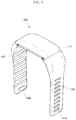
- FIG. 1 is a view showing a location tracking device according to an embodiment of the present invention.
- the present invention is based on a wearable location tracking device 100 based on the functional combination of low-power and long-time data transmission.
- the wearable location tracking device 100 may include an accelerometer 219 for detecting an emergency situation according to a sudden change of user's state and fall down.
- the wearable location tracking device 100 may include location tracking modules such as a Global Positioning System (GPS), a Bluetooth Low Energy (BLE), a WIFI Sniffing, and an Ultra Wide Band (UWB).
- the wearable location tracking device may transmit a location tracking data using a IoT communication network or a real-time communication network according to situation analysis information.
- the location tracking device may include a solar charging module and an energy harvest module for self-power generation.
- the location tracking device 100 may include a body member 110, a first band member 121, a second band member 122 and a flexible battery 140.
- the body member 110 may have a circuit board including various modules for geo-fence service ( FIG. 4 ). Accordingly, the user may be tracked while wearing the location tracking device 100 according to an embodiment of the present invention.
- the body member 110 may include, for example, an upper portion 111 and a lower portion 113.
- the flexible battery 140 and modules to be described later may be located between the upper portion 111 and the lower portion 113.
- the coupling structure of the upper portion 111 and the lower portion 113 may, for example, form a locking jaw 112 on an inner surface of the upper portion 111 and a locking ring 114 on an inner surface of the lower portion 113.
- each of the locking jaws 112 and the locking rings 114 may correspond to each other one-to-one.
- fastening the upper portion 111 and the lower portion 113 with bolts may be to facilitate repair and maintenance and to improve the fastening force of the location tracking device 100 according to an embodiment of the present invention.
- a sealing ring 115 may be interposed between portions of the body member 110 in which the upper portion 111 and the lower portion 113 are in close contact with each other.
- the sealing 115 may be formed in line shape and may be positioned along a portion where the upper portion 111 and the lower portion 113 are in close contact.
- the material of the sealing 115 may be, for example, rubber, silicone and synthetic resin.
- the sealing 115 may seal a gap between the upper portion 111 and the lower portion 113 to prevent moisture or foreign substances from entering the body member 110 from the outside.
- the first band member 121 and the second band member 122 may be respectively coupled to both ends of the body member 110.
- the fastening structure of the first band member 121 and the second band member 122 may be, for example, to form a plurality of coupling holes 121a at regular intervals along the longitudinal direction of the first band member 121. Then, a coupling protrusion 122a may be formed on one side surface of the end of the second band member 122. Depending on the circumference of the user's wrist, the coupling protrusion 122a may be coupled to any one of the pluralities of coupling holes 121a.
- the fastening structure of the first band member 121 and the second band member 122 may be not limited to the above structure, and any of the first band member 121 and the second band member 122 may be used as long as they are stably coupled to each other. Accordingly, the first band member 121 and the second band member 122 may be freely deformed by an external force to be in close contact with the user's wrist.
- the material of the first band member 121 and the second band member 122 may be, for example, Thermoplastic Poly Urethane (TPU). Accordingly, the first band member 121 and the second band member 122 may be freely deformed by an external force to be in close contact with the user's wrist.
- TPU Thermoplastic Poly Urethane
- the gap may be prevented from being generated in a portion coupled with the body member 110.
- first band member 121 and the second band member 122 are not limited to being the TPU, and may be any materials that are deformed by external force and restored to their initial shape.
- a portion of the flexible battery 14 may be accommodated inside the body member 100, and the other ends of the flexible battery 14 may be accommodated inside the first band member 121 and the second band member 122.
- the middle portion of the flexible battery 140 may be accommodated in the body member 110.
- the other ends of the flexible battery 140 may be accommodated in each of the first band member 121 and the second band member 122. That is, one flexible battery 140 may be built to span the body member 110, the first band member 121, and the second band member 122.
- the length of the flexible battery 140 may be increased compared to a structure in which a general battery is embedded only in the body member 110. Therefore, the storage capacity of the flexible battery 140 may be also increased to increase the use time of the location tracking device 100 according to an embodiment of the present invention.
- each of the first band member 121 and the second band member 122 may include a receiving portion 123 in which a portion of an end of the flexible battery 140 is accommodated in a portion coupled to the body member 110.
- the receiving portion 123 may be formed to have a size relatively larger than that of the flexible battery 140. This is to allow the flexible battery 140 to be freely deformed in the receiving portion 123.
- the wrinkled portion of the flexible battery 140 may be freely bent along with deformation of the first band member 121 and the second band member 122.
- the flexible battery 140 for this may be made to have a length as an example.
- all or a portion of a portion accommodated in the receiving portion 123 in the flexible battery 140 may be formed to be wrinkled. For example, only the portion accommodated in the receiving portion 123 in the flexible battery 140 may be wrinkled.
- the first band member 121 and the second band member 122 among the portions accommodated in the first band member 121 and the second band member 122 may be deformed by an external force to form wrinkles.
- a portion accommodated in the body member 110 may be plate-shaped, and the remaining portions may be formed to be wrinkled. Accordingly, since the entire thickness of the body member 110 may be reduced by a thickness increased by wrinkles in the flexible battery 140, the appearance of the location tracking device 100 according to an embodiment of the present invention may have a good shape and also improve a wearing sensation.
- the location tracking device 100 may include a wireless power transmission unit (see FIG. 4 , 130), a circuit board 150 on which various modules are mounted, and a connecting member 160.
- the wireless power transmission unit 130 may be located inside the body member 110 to receive wireless power to supply power to the flexible battery 140. That is, the above-described flexible battery 140 may be charged by the wireless power transmission unit 130.
- the method for the wireless power transmission unit 130 to receive power may be, for example, a magnetic resonance method or a magnetic induction method, but is not limited thereto, and any method may be used as long as it can receive power wirelessly.
- the circuit board 150 may be located inside the body member 110 and positioned above the flexible battery 140. Various modules for operating the location tracking device 100 according to an embodiment of the present invention may be mounted on the circuit board 150.
- a WIFI 201, a UWB 203, a LPWAN 205, a GPS 213, a accelerometer 219, a BLE/MCU 211, a solar charging module, a battery 207, an energy harvest module 215, a power/charging 209 modules may be mounted in the circuit board 150.
- an overcharge protection circuit that prevents overcharging of the flexible battery 140 may also be mounted on the circuit board.
- the vibration unit 152 through which the user can feel vibration may be mounted on the circuit board 150.
- the WIFI 201 may be a wireless local area net-work (WLAN) that converts a wired LAN transmission method to suit a wireless environment and can be used for location tracking when in an indoor environment.
- WLAN wireless local area net-work
- the UWB 203 may be for a high-speed transmission of 500 Mbps, which is about 10 times the speed of a wireless LAN, which is about 54 Mbps. Therefore, the UWB 203 may be used to implement two-way services such as automotive Intelligent Transport System (ITS) communication and disaster rescue communication.
- ITS automotive Intelligent Transport System
- the battery 207, the flexible battery, and the energy harvesting device using a Peltier element may be provided as a separate power source for supplying auxiliary power to the circuit board.
- the BLE 211 which is the location tracking communication method may be used for location tracking in the indoor environment.
- the GPS 213 may be a satellite navigation system that receives the signal from a GPS satellite and used for location tracking in the outdoor environment.
- the accelerometer 219 may be a device for measuring acceleration, and a means for detecting a sudden change in user behavior and grasping a fall-down or other emergency.
- the solar charging module 217 may be for solar charging when the position of the location tracking device is in the outdoor state.
- the energy harvest module 215 may be a module of producing self-power by using a change in body temperature of person or animal, and expand the amount of power of location tracking device 100 combined with the solar charging module 217 and the flexible battery 140.
- the other control unit (MCU, 211) may be in charge of controlling all the modules in the location tracking device.
- the control unit 211 of the location tracking device 100 may determine whether it is an emergency or a normal (or peaceful) situation based on information of situation recognition of the location tracking device 100. If it is determined that the situation is the normal, the LPWAN 205 module may be used to transmit the location tracking data of the location tracking device to the low-power communication network.
- the low power communication network may be a Sigfox, Long Range (LoRa), and Narrow Band - Internet of Things (NB-IoT) communication network, use a broadcasting transmission method.
- the UWB module may be used to transmit the emergency message and the location tracking data of the location tracking device to network for real-time and bidirectional communication.
- the location tracking data may be usually transmitted to the network in a low-power communication method.
- the location tracking data may be transmitted to the network by switching to the real-time communication method even if the power consumption is high.
- the solar charging module 217 may be activated, and the charged power of solar charging module 217 may be provided to the location tracking device 100.
- the location of the location tracking device 100 may be determined in the outdoor.
- the GPS Module 213 may be used to measure the location value of the location tracking device to the network.
- the location of the location tracking device 100 may be determined indoor.
- the one of the BLE 211, the WIFI 201 and the UWB 203 modules other than the GPS 213 module may be used for tracking the location data of the location tracking device.
- the connecting member 160 may be electrically connected to the circuit board 150.
- One end of the connecting member 160 for this purpose may be coupled to the circuit board 150.
- the other end of the connecting member 160 may be positioned below the flexible battery 140.
- the location tracking device 100 may include a display module 151.
- the display module 151 may be located on the circuit board 150.
- the display module 151 may display an operation state of the location tracking device 100 according to an embodiment of the present invention.
- the display module 151 may be a flat display panel positioned at a predetermined distance from the upper portion 111 of the body member 110.
- the display module 151 may be a flexible display panel as another example.
- the outer surface of the upper portion 111 of the body member 100 may be a curved surface.
- the inner surface of the upper portion 111 of the body member 110 may also be a curved surface.
- a cover window may be formed on the outer surface of the upper portion 111.
- the flexible display panel may be attached to the cover window in the curved state. Accordingly, by outputting an image in the curved state from the flexible display panel, the image may be output to the flexible display panel even if the user watches from various angles while wearing the location tracking device 100 according to an embodiment of the present invention. Since the flexible display panel is a known flexible display panel, detailed description thereof will be omitted.
- the upper portion 111 of the body member 100 from the top to the bottom, the display module 151, the circuit board 150, the flexible battery 170 and the lower portion 113 of the body member 110 may be sequentially positioned.
- connection member 160 may be a flexible printed circuit board (FPCB).
- FPCB flexible printed circuit board
- the aforementioned wireless power transmission unit 130 may receive power from an external power supply (not shown).
- the external power supply is a known wireless charger, detailed descriptions of the structure and operation process thereof may be omitted.
- the wireless power transmission unit 130 may include, for example, a rectification unit 131, a power detection unit 132, and a message modulation/demodulation unit 133, a power reception control unit 134, and a power reception antenna 135.
- the rectifying unit 131 may perform full-wave rectification to convert a wireless power signal in an Alternating Current (AC) state received from the power receiving antenna 135 into a Direct Current (DC).
- the rectifying unit 131 may further include a smoothing circuit for making the rectified current into a flat and stable direct current.
- the power detection unit 132 may monitor the voltage or current of the power rectified by the rectification unit 131.
- the message modulation/demodulation unit 133 may be used to demodulate the wireless power signal by the power reception control unit 134 and transmit the power control message signal.
- the power reception control unit 134 may control each component included in the wireless power transmission unit 130.
- the power receiving antenna 135 may be formed in various shapes and sizes according to the wireless charging method of the wireless power transmission unit 130.
- the power receiving antenna 135 may be formed by patterning a conductor such as copper foil on at least one surface of the synthetic resin or forming a loop-shaped metal pattern using conductive ink.
- the power receiving antenna 135 may be, for example, a flexible printed circuit board antenna.
- the flexible printed circuit board antenna may be an antenna pattern printed on a flexible printed circuit board.
- the power receiving antenna 135 may have a size similar to that of the circuit board 150 described above, or may be relatively smaller than the circuit board 150, but is not limited thereto.
- the power receiving antenna 135 may have an overall shape in a film shape, and an adhesive layer may be formed on each of both sides. Accordingly, one surface of the receiving power antenna 135 may be attached to the connecting member 160, and the other surface may be attached to another adjacent member. To this end, the portion of the connection member 160 to which the power receiving antenna 135 is attached may be formed to have a size corresponding to the circuit board 150. With this structure, the assembly of the location tracking device 100 according to an embodiment of the present invention may be quickly implemented.
- the location tracking device 100 may also be configured as a combo type that further includes at least one of an antenna for magnetic secure transmission (MST) and an antenna for near field communication (NFC).
- MST magnetic secure transmission
- NFC near field communication
- the location tracking device 100 may include a shielding sheet 136.
- the shielding sheet 136 may be located between the power receiving antenna 135 and the flexible battery 140.
- the shielding sheet 136 may be adhered to the power receiving antenna 135 by adhesion formed on one surface of the power receiving antenna 136.
- the shielding sheet 136 may shield the magnetic field generated by the radio signal induced by the antenna and focus in a desired direction.
- the shielding sheet 136 may be a ferrite sheet or an amorphous sheet made of a plate-like member having a predetermined area, or a hybrid sheet formed by stacking them.
- the ferrite sheet may be made of a sintered ferrite sheet, and may be made of MnZn ferrite or NiZn ferrite.
- the amorphous sheet may be a ribbon sheet including at least one of an amorphous alloy and a nanocrystalline alloy, and the ribbon sheet may be stacked in multiple layers, and the flakes processing may be performed by separated into a plurality of fine pieces, and the gaps between the separated fine pieces may be isolated by filling with an adhesive.
- the location tracking device 100 may include the wireless power transmission unit 130 so that charging can be performed as long as it is located on the charging stand.
- the location tracking device 100 according to the present invention can be charged using the wireless charger without connecting the charging cable to the body member 110, unlike the conventional location tracking device, convenience in use can be improved.
- a charging port which is an essential component for connecting the charging cable, does not have to be provided, thereby preventing failure due to foreign matter and moisture.
- the user may very easily handle and manage the location tracking device 100.
- the location tracking device 100 according to the present invention does not have the charging port through which the inside of the body member 110 is exposed to the outside, thereby improving the cohesiveness and easily implementing a structure for waterproofing.
- the location tracking device 100 can additionally utilize as much space as the space occupied by the charging port, the design freedom can be increased by adding additional functions or changing innovative design.
- the above-described flexible battery 140 may include, for example, an electrode assembly 141 and exterior materials 147 and 148, and the electrode assembly 141 may include the exterior material 147 together with an electrolyte.
- the electrode assembly 141 and the exterior materials 147 and 148 are provided with patterns 146 and 149 for contraction and relaxation in the longitudinal direction, respectively, and a first pattern formed on the exterior materials 147 and 148 and a second pattern 146 formed on the electrode assembly 141 may be provided to have the same directionality with each other.
- the amount of deformation of the base material constituting the electrode assembly 141 and the exterior materials 147 and 148 is prevented or minimized, the amount of deformation of the substrate itself that can occur in the bent portion is minimized. It is possible to prevent the electrode assembly 141 and the exterior materials 147 and 148 from being damaged or deteriorating.
- first pattern 149 and the second pattern 146 are arranged such that the first pattern 149 and the second pattern 146 may coincide with each other as well as the same directionality. This is to ensure that the first pattern 149 and the second pattern 146 always have the same moving.
- the flexible battery 140 may be formed so that the patterns 146 and 149 for contraction and displacement in the longitudinal direction generated coincide with the electrode assembly 141 and the exterior materials 147 and 148, when bending is occurred. Even if the warp in the direction occurs, the electrode assembly 141 and the exterior materials 147 and 148 may be able to maintain a uniform spacing or contact state with respect to the entire length. Therefore, the electrolyte solution sealed together with the electrode assembly 141 may be uniformly distributed over the entire length, so that performance of the battery may be prevented from deteriorating.
- the first pattern 149 and the second pattern 146 may be formed in a parallel direction to the width direction of the exterior portions 147 and 148 and the electrode assembly 141, respectively, and the exterior portions 147 and 148 and the electrode assembly 141 along the longitudinal direction may be alternately arranged in the hills and valleys.
- the hills and valleys constituting the first pattern 149 and the second pattern 146 may be formed at the same position, so that the first pattern 149 and the second pattern 146 may be coincide with each other.
- the hills and valleys of the first pattern 149 and the second pattern 146 may be parallel direction to the straight lines parallel to the width direction of the exterior materials 147 and 148 and the electrode assembly 141.
- the hills and valleys of the first pattern 149 and the second pattern 146 may be repeatedly arranged along the longitudinal direction.
- the patterns 246 and 149 may be continuously formed in a direction parallel to the width direction of the electrode assembly 141 and the exterior materials 147 and 148, or formed discontinuously.
- the pattern 246 and 149 may be formed for the entire length of the electrode assembly 141 and the exterior materials 147 and 148, or formed partially for some lengths.
- the patterns 146 and 149 of the flexible battery 140 may be formed in portions accommodated in the first band member 121 and the second band member 122.
- the patterns 146 and 149 of the flexible battery 140 may be formed only in portions where the first band member 121 and the second band member 122 are deformed by external force among the portions accommodated in the first band member 121 and the second band member 122.
- the hill and valley portions may be provided to have a cross-section of various shapes in which an arc-shaped cross section including a semicircle, a polygonal cross section including a triangle or a square, and an arc-shaped cross section and a polygonal cross section may be mutually combined.
- Each of the peaks and valleys may be provided to have the same pitch and width, but may be provided to have different pitches and widths.
- first pattern 149 and the second pattern 146 may be formed to have the same distance the interval between valleys adjacent to each other and the interval between hills adjacent to each other, or may be provided to have different intervals. The same interval and each other intervals may be provided in combination.
- first pattern 149 formed on the exterior materials 147 and 148 may be formed on the entire surface of the exterior materials 147 and 148, but may be partially formed.
- first pattern 149 may be formed only in portions accommodated in the first band member 121 and the second band member 122 in the exterior materials 147 and 148.
- the electrode assembly 141 may be sealed with an electrolyte inside the exterior materials 147 and 148 and include an anode 142, a cathode 144, and a separator 143.
- the positive electrode 142 may include a positive electrode current collector 142a and a positive electrode active material 142b
- the negative electrode 144 may include a negative electrode current collector 144a and a negative electrode active material 144b
- the positive electrode current collector 142a and the negative electrode current collector 144a may be implemented in the form of a sheet having a predetermined area.
- the positive electrode 142 and the negative electrode 144 may be provided for the entire area of the active materials 142b and 144b on one or both surfaces of each current collector 142a and 144a, or partially provided for some areas.
- the positive electrode current collector 142a and the negative electrode current collector 144a may have negative electrode terminals 145a and positive electrode terminals 145b, respectively, for electrical connection with the outside.
- the positive electrode terminal 145b and the negative electrode terminal 145a may be provided in a form extending from the positive electrode current collector 142a and the negative electrode current collector 144a to protrude on one side of the exterior bodies 147 and 148.
- the positive electrode terminal 145b and the negative electrode terminal 145a may be provided to be exposed on the surfaces of the exterior materials 147 and 148.
- the positive electrode active material 142b and the negative electrode active material 144b may contain a polytetrafluoroethylene (PTFE) component. This is to prevent the positive electrode active material 142b and the negative electrode active material 144b from peeling or cracking from the current collectors 142a and 144a during bending.
- PTFE polytetrafluoroethylene
- the separator 143 disposed between the anode 142 and the cathode 144 may include a nanofiber web layer 143b on one or both surfaces of the nonwoven layer 143a.
- the nanofiber web layer 143b may be a nanofiber containing at least one selected from polyacylonitrile nanofibers and polyvinylidene fluoride nanofibers.
- the nanofiber web layer 143b may be composed of polyacrylic knit nanofibers only to ensure radioactivity and uniform pore formation.
- the exterior materials 147 and 148 may be formed of a plate-shaped member having a predetermined area, and may be intended to protect the electrode assembly 141 from external force by receiving the electrode assembly 141 and an electrolyte therein.
- the exterior materials 147 and 148 may be provided with a pair of first exterior materials 147 and a second exterior material 148, and sealed through an adhesive along the rim, the electrolyte solution and the electrode assembly 141 accommodated therein are prevented from being exposed to the outside and prevented from leaking to the outside.
- the exterior materials 147 and 148 may be sealed with an edge portion constituting the sealing portion through an adhesive.
- the exterior materials 147 and 148 are made of a single member, and after being folded in half along the width direction or the length direction, the rest of the contact portions may be sealed through an adhesive.
- the flexible battery 140 may be freely deformed by an external force by having the above-described structure.
- FIG. 9 is a state definition and various state transition diagrams for state recognition of the location tracking device 1 for the present invention.
- the Standby Status may refer a standby status after the initialization of the location tracking device 1, at which time a system check of the location tracking device 1 is performed.
- a Sensor Sensing Status may refer a status that measures a heart rate, a body temperature, and an acceleration, and checks whether this state is an emergency or not.
- An Emergency Status may refer a status of processing when the emergency state occurs according to the definition of the emergency.
- a Status Analysis may mean a status that is in charge of analyzing and managing information from each status.
- An Indoors/Outdoors detection may mean a location analysis on whether the location of the location tracking device 1 is in an indoor or an outdoor.
- An Indoor Status may refer a status of processing and managing when the location of the location tracking device 1 is in the indoor.
- An Outdoor Status may refer to a status of processing and managing when the location of the location tracking device 1 is in the outdoor.
- An Indoor Interference Status may refer a status of checking and observing the change of location data in the indoor.
- An Outdoor Interference Status may refer a status of checking and observing the change of location data in the outdoor.
- a Geo-Fencing Control Status may refer a status in which a processing for the location tracking device 1 when the user leaves the geo-fence.
- all status can be transitioned to other status at any time or freely.
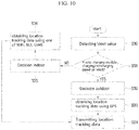
- FIG. 10 is a flowchart of method for providing a low-power geo-fence service based on the location tracking device according to the present invention.
- a Vrect value serving as a reference value for determining a charging/non-charging state of the solar charging module 217 may be decided (S30).
- the Vrect value may be a reference value to determine that the location of the location tracking device 100 is indoor or shaded area.
- the Vrect value may be a reference value to determine that the location of the location tracking device 100 is outdoor.
- the Vrect is decided by using various history values obtained from the solar charging module 217 of the location tracking device 100.
- the location tracking module suitable for Indoor/Outdoor may be quickly selected, thereby reducing power consumption for searching the location tracking module of the location tracking device.
- the solar charging module 217 of the location tracking device 100 is in a charging situation, it may be determined that the location of the location tracking device is outdoor (S32).
- the location tracking data is acquired using only the GPS module (S33).
- the solar charging module 217 of the location tracking device 100 may be determined that the location of the location tracking device 100 is indoor (S35).
- location tracking data is acquired by one of the BLE, the WIFI, and the UWB module other than the GPS module (S36).
- the acquired location tracking data is transmitted to the network using the low-power communication method (S34).
- the low-power communication method may be Sigfox, LoRa, or NB-IoT, and referred to as a low-power communication method of one-way broadcasting that does not transmit a response message for a received signal.
- FIG. 11 is a flowchart showing a method for determining the location of the location tracking device 100 of FIG. 10 to be Outdoor and obtaining location tracking data using a GPS module.
- the step of determining that the location of the location tracking device 100 is outdoor may include the step of determining whether the location tracking data using the GPS module is detected stably (S44).
- the location tracking data is not stably detected, it may be determined that the location of the location tracking device 100 is indoor (S45).
- location tracking data is acquired using one of the BLE, the WiFi, and the UWB module other than the GPS module (S46).
- FIG. 12 is a flowchart of method for determining location of the location tracking device of FIG. 1 to be indoor and acquiring location tracking data using any one of the BLE, the WIFI, and the UWB module.
- the location tracking data is acquired using any one of the BLE, the WIFI, and the UWB modules other than the GPS module (S50 ⁇ S54).
- the location tracking module is changed with the remaining other location tracking module (S56 ⁇ S65).
- the location tracking data may be acquired using the determined location tracking module (S64).
- location tracking module which is the most stably obtainable the location tracking data is searched such like an example of FIG 12.
- FIG. 12 shows a process of searching the location tracking module among the BLE, the WIFI, and the UWB
- the location tracking module which is the most stably obtainable the location tracking data may refer that the location tracking module can obtain the location tracking data most quickly without failure. If there is some delay or failure to obtain the location tracking data with the location tracking module, the module may be not stable to get the location tracking data in the location. That is, the location tracking module which is the most stably obtainable the location tracking data may have the least delay time and the least failure chances to obtain the location tracking data.
- the location tracking data may not be detected stably using the BLE, the WIFI, or the UWB module, it may be determined to be the outdoor and the location tracking data may be acquired using the GPS (S52).
- the present disclosure to provide a location tracking device for geo-fence service, which has the solar charging module and the energy harvest module for self-power generation and applies a low-power communication method and location tracking modules.
- present invention to provide a location tracking method for providing the low-power consuming geo-fence service by selecting the location tracking module based on the indoor/outdoor information decided by operation of the solar charging module.
Landscapes
- Health & Medical Sciences (AREA)
- Engineering & Computer Science (AREA)
- General Health & Medical Sciences (AREA)
- Child & Adolescent Psychology (AREA)
- Emergency Management (AREA)
- General Physics & Mathematics (AREA)
- Physics & Mathematics (AREA)
- Business, Economics & Management (AREA)
- Computer Networks & Wireless Communication (AREA)
- Signal Processing (AREA)
- Radar, Positioning & Navigation (AREA)
- Computing Systems (AREA)
- Toxicology (AREA)
- Environmental & Geological Engineering (AREA)
- Remote Sensing (AREA)
- Psychiatry (AREA)
- Psychology (AREA)
- Social Psychology (AREA)
- Gerontology & Geriatric Medicine (AREA)
- Charge And Discharge Circuits For Batteries Or The Like (AREA)
- Telephone Function (AREA)
Abstract
Description
- The present invention relates a method and device of location tracking for providing low power consuming geo-fence service by using an indoor/outdoor location information based on solar charging module estimation, in detail, the present invention relates the method and device of location tracking for providing the low-power consuming geo-fence service by selecting a location tracking module based on the indoor/outdoor information decided by operation of the solar charging module.
- Recently, the geo-fence service of location tracking device using the low-power communication have been proposed for the elderly people with dementia to prevent death or injury due to in-home departure and zone departure. In addition, the market for devices for providing such service and communication method targeting elderly people with dementia is expanding to pet and livestock.
- In general, the Geo-Fence is a compound word of Geographic and Fence, and refers to a virtual fence installed in a specific geographic area using a location-based service (LBS). The Geo-Fencing is an application program interface (API) that supports the virtual fence on a specific area.
- The Geo-Fencing is an interface using a Global Positioning System (GPS), which is one of the location tracking technologies, and allows a user to check an access status of virtual fence by designating the virtual fence in the form of a circle or a square in the specific area through the GPS.
- However, since the currently used Geo-Fence service is provided using a mobile communication network, a Bluetooth communication, or a Wireless Fidelity (WIFI) communication, the service fee is expensive, or the service is available only in the area where specific communication equipments are installed. Moreover, due to the limitation of the battery capacity of the location tracking device, there have been difficulties in expanding the service.
- Accordingly, in order to overcome high cost, tracking distance, and limitation of battery capacity, devices and methods using low power location tracking method and communication method have been proposed.
- An effective power consuming Geo-Fence service is needed through combining an advantage of low power communication network, a Soft Ware (SW) platform having compatibility for various data and an effective analysis engine of wearable device such as the location tracking device.
- It is an object of the present invention to provide a location tracking device for geo-fence service, which has a solar charging module and an energy harvest module for self-power generation and applies a low-power communication method and location tracking modules.
- In addition, it is an object of the present invention to provide a location tracking method for providing the low-power consuming geo-fence service by selecting a location tracking module based on the indoor/outdoor information decided by operation of the solar charging module.
- To solve the above problem and defects, the present invention provides a device A device of location tracking for providing low power consuming geo-fence service in wireless network, comprising: a body member; a first bend member and a second bend member; a flexible battery having a predetermined length, inserted into a receiving portion of the first and second band members, and disposed so that the remaining length except for the portion inserted in the receiving portion is located inside the body member; a solar charging module for producing self-power; and a circuit board including at least one of a Global Positioning System (GPS), a Bluetooth Low Energy (BLE), a Wireless Fidelity (WIFI) Sniffing, and an Ultra-Wide Band (UWB) modules and a Low Power Wide Area Network(LPWAN) and Ultra-Wide Band (UWB) modules for a location tracking and a communicating with a network, and a control unit (MCU) for controlling the location tracking device ; wherein the control unit switch the communication module according to a detected operation of solar charging module.
- In an embodiment of the present invention , wherein control unit determines the communication module as the LPWAN module when a user of the location tracking device is in a normal situation, wherein the control unit determines the communication module as the UWB module when the user of the location tracking device is in an emergency situation.
- In an embodiment of the present invention, wherein the control unit determines that the location of the location tracking device is outdoor and the location tracking data is obtained using the GPS module when the solar charging module is a charging operation, wherein the control unit determines that the location of the location tracking device is indoor and the location tracking data is obtained by one of the BLE, the WIFI, and the UWB module other than the GPS module when the solar charging module is a non-charging operation.
- In an embodiment of the present invention, wherein the LPWAN communication module transmits the locating tracking data through one of a Sigfox, a Long Range (LoRa), and a Narrow Band - Internet of Things (NB-IoT) communication network using a broadcasting communication method, wherein the UWB communication module transmits the locating tracking data through an LTE (Long-term evolution) mobile communication network using a bidirectional communication method that transmits a response message for the location tracking data.
- To solve the above problem and defects, the present invention provides a method of location tracking for providing low power consuming geo-fence service in a location tracking device, comprising: detecting a Vrect value which is a reference value for determining a charging or a non-charging operation of the solar charging module; determining whether the solar charging module is charging operation or non-charging operation based on the detected the Vrect value; determining that a location of the location tracking device is outdoor and a location tracking data is obtained using a Global Positioning System (GPS) module when the solar charging module is in the charging operation; determining that a location of the location tracking device is indoor and a location tracking data is obtained using one of a Bluetooth Low Energy (BLE), a Wireless Fidelity (WIFI) Sniffing, and an Ultra-Wide Band (UWB) modules other than the GPS module when the solar charging module is in the non-charging operation; and transmitting the location tracking data through a Low Power Wide Area Network (LPWAN) communication module.
- In an embodiment of the present invention, wherein the location tracking data is acquired using the GPS module, further comprising: determining whether the location tracking data obtained using the GPS module is stably obtained, and if the location tracking data is not stably obtained using the GPS module, determining the location of the location tracking device is indoor and obtaining the location tracking data using one of the BLE, the WIFI, and the UWB module.
- In an embodiment of the present invention, wherein the location tracking data is acquired by one of the BLE, the WIFI, and the UWB module other than the GPS module, further comprising: determining whether location tracking data is stably obtained using the location tracking module used before determining the location of the location tracking device is indoor according to the solar charging module, searching other location tracking module which is most stably obtainable the location tracking data when the location tracking data is not stably obtained using the used location tracking module, and obtaining the location tracking data by the searched location tracking module, wherein the location tracking module which is the most stably obtainable the location tracking data has the least delay time and the least failure chances to obtain the location tracking data.
- In an embodiment of the present invention, wherein the LPWAN communication module transmits the locating tracking data through one of a Sigfox, a Long Range (LoRa), and a Narrow Band - Internet of Things (NB-IoT) communication network using a broadcasting communication method.
- In an embodiment of the present invention, the location tracking device includes status definitions that a Standby Status referring a standby state after the initialization of the location tracking device, a Sensor Sensing Status referring a state that measures a heart rate, a body temperature, and an acceleration, an Emergency Status referring a state of processing when the defined emergency situation is occurred, a Status Analysis referring a state of analyzing and managing information from each status, an Indoors/Outdoors detection referring a state of analyzing whether the location of the location tracking device is indoor or outdoor, an Indoor Status referring a state of processing and managing when the location of the location tracking device is indoor, an Outdoor Status referring a state of processing and managing when the location of the location tracking device is outdoor, an Indoor Interference Status referring a state of checking and observing the change of location data indoor, an Outdoor Interference Status referring a state of checking and observing the change of location data in the outdoor, a Geo-Fencing Control Status referring a state of processing when the user deviates from the geo-fence.
- In an embodiment of the present invention, wherein the Vrect value is the reference value determining that the location tracking device is indoor and the reference value determining that the location tracking device is outdoor.
- The effect of the present invention is to increase the power supply amount of the location tracking device by producing self-generation power of solar charging module and the energy harvesting module in the location tracking device, thereby providing long time geo-fence service in location tracking device.
- That is, the location tracking module can be quickly selected according to the indoor/outdoor location information of the location tracking device to which the solar charging module is applied, thereby reducing power consumption for searching the location tracking module of the location tracking device.
- In addition, the flexible battery to be accommodated in the body member, the first band member, and the second band member of the location tracking device can increase the battery size compared to a wearable device in which a general battery is embedded only in the body member.
-
-
FIG. 1 is a view showing a location tracking device according to an embodiment of the present invention. -
FIG. 2 is an exploded perspective view of the location tracking device ofFIG. 1 -
FIG. 3 is a block diagram of modules configured on a circuit board inside the body of the location tracking device according to the present invention. -
FIG. 4 is a configuration diagram of a wireless power transmission unit included in the location tracking device according to the present invention. -
FIG. 5 shows a power receiving antenna included in the wireless power transmission unit. -
FIG. 6 is a diagram illustrating a flexible battery extracted from the location tracking device according to the present invention. -
FIG. 7 is an exemplary view showing various patterns applied to the electrode assembly and the exterior material in the flexible battery ofFIG. 6 , and is a view showing various distances between adjacent valleys or hills of the exterior material in the flexible battery. -
FIG. 8 is an enlarged view of the inside of the flexible battery ofFIG. 6 . -
FIG. 9 is a state definition and various state transition diagrams for recognizing a situation of the location tracking device according to the present invention. -
FIG. 10 is a flowchart of method for providing a low-power geo-fence service based on the location tracking device according to the present invention. -
FIG. 11 is a flowchart of method for determining a location of the location tracking device ofFIG. 1 to be outdoor and obtaining location tracking data using a GPS module. -
FIG. 12 is a flowchart of method for determining location of the location tracking device ofFIG. 1 to be indoor and obtaining location tracking data using any one of a BLE, a WIFI, and a UWB module. - Hereinafter, exemplary embodiments of the present disclosure will be described in detail with reference to the accompanying drawings, which will be readily apparent to those skilled in the art to which the present disclosure pertains. The present disclosure may be embodied in many different forms and is not limited to the embodiments described herein. In the drawings, portions not relating to the description are omitted for clarifying the present disclosure, and the same reference numerals are assigned to the same or similar components throughout the specification.
-
FIG. 1 is a view showing a location tracking device according to an embodiment of the present invention. - The present invention is based on a wearable
location tracking device 100 based on the functional combination of low-power and long-time data transmission. The wearablelocation tracking device 100 may include anaccelerometer 219 for detecting an emergency situation according to a sudden change of user's state and fall down. - The wearable
location tracking device 100 may include location tracking modules such as a Global Positioning System (GPS), a Bluetooth Low Energy (BLE), a WIFI Sniffing, and an Ultra Wide Band (UWB). The wearable location tracking device may transmit a location tracking data using a IoT communication network or a real-time communication network according to situation analysis information. The location tracking device may include a solar charging module and an energy harvest module for self-power generation. - It is based on the functional combination of low-power and long-time data transmission, which is an advantage of the low power communication method and self-power generation.
- The
location tracking device 100 according to an embodiment of the present invention, as shown inFIG 1 and2 may include abody member 110, afirst band member 121, asecond band member 122 and aflexible battery 140. - The
body member 110 may have a circuit board including various modules for geo-fence service (FIG. 4 ). Accordingly, the user may be tracked while wearing thelocation tracking device 100 according to an embodiment of the present invention. - The
body member 110 may include, for example, anupper portion 111 and alower portion 113. Theflexible battery 140 and modules to be described later may be located between theupper portion 111 and thelower portion 113. The coupling structure of theupper portion 111 and thelower portion 113 may, for example, form alocking jaw 112 on an inner surface of theupper portion 111 and alocking ring 114 on an inner surface of thelower portion 113. - The number and position of each of the
locking jaws 112 and thelocking rings 114 may correspond to each other one-to-one. In addition, fastening theupper portion 111 and thelower portion 113 with bolts may be to facilitate repair and maintenance and to improve the fastening force of thelocation tracking device 100 according to an embodiment of the present invention. - Meanwhile, a sealing
ring 115 may be interposed between portions of thebody member 110 in which theupper portion 111 and thelower portion 113 are in close contact with each other. The sealing 115 may be formed in line shape and may be positioned along a portion where theupper portion 111 and thelower portion 113 are in close contact. The material of the sealing 115 may be, for example, rubber, silicone and synthetic resin. The sealing 115 may seal a gap between theupper portion 111 and thelower portion 113 to prevent moisture or foreign substances from entering thebody member 110 from the outside. - The
first band member 121 and thesecond band member 122 may be respectively coupled to both ends of thebody member 110. - The fastening structure of the
first band member 121 and thesecond band member 122 may be, for example, to form a plurality ofcoupling holes 121a at regular intervals along the longitudinal direction of thefirst band member 121. Then, acoupling protrusion 122a may be formed on one side surface of the end of thesecond band member 122. Depending on the circumference of the user's wrist, thecoupling protrusion 122a may be coupled to any one of the pluralities ofcoupling holes 121a. - However, the fastening structure of the
first band member 121 and thesecond band member 122 may be not limited to the above structure, and any of thefirst band member 121 and thesecond band member 122 may be used as long as they are stably coupled to each other. Accordingly, thefirst band member 121 and thesecond band member 122 may be freely deformed by an external force to be in close contact with the user's wrist. - The material of the
first band member 121 and thesecond band member 122 may be, for example, Thermoplastic Poly Urethane (TPU). Accordingly, thefirst band member 121 and thesecond band member 122 may be freely deformed by an external force to be in close contact with the user's wrist. - As described above, since the
first band member 121 and thesecond band member 122 are made of TPU for the compression deformation by external force, the gap may be prevented from being generated in a portion coupled with thebody member 110. - However, the
first band member 121 and thesecond band member 122 are not limited to being the TPU, and may be any materials that are deformed by external force and restored to their initial shape. - A portion of the flexible battery 14 may be accommodated inside the
body member 100, and the other ends of the flexible battery 14 may be accommodated inside thefirst band member 121 and thesecond band member 122. - For example, the middle portion of the
flexible battery 140 may be accommodated in thebody member 110. In addition, the other ends of theflexible battery 140 may be accommodated in each of thefirst band member 121 and thesecond band member 122. That is, oneflexible battery 140 may be built to span thebody member 110, thefirst band member 121, and thesecond band member 122. - With this structure, the length of the
flexible battery 140 may be increased compared to a structure in which a general battery is embedded only in thebody member 110. Therefore, the storage capacity of theflexible battery 140 may be also increased to increase the use time of thelocation tracking device 100 according to an embodiment of the present invention. - Meanwhile, each of the
first band member 121 and thesecond band member 122 may include a receivingportion 123 in which a portion of an end of theflexible battery 140 is accommodated in a portion coupled to thebody member 110. - The receiving
portion 123 may be formed to have a size relatively larger than that of theflexible battery 140. This is to allow theflexible battery 140 to be freely deformed in the receivingportion 123. - The wrinkled portion of the
flexible battery 140 may be freely bent along with deformation of thefirst band member 121 and thesecond band member 122. Theflexible battery 140 for this may be made to have a length as an example. In addition, all or a portion of a portion accommodated in the receivingportion 123 in theflexible battery 140 may be formed to be wrinkled. For example, only the portion accommodated in the receivingportion 123 in theflexible battery 140 may be wrinkled. - In
flexible battery 140, thefirst band member 121 and thesecond band member 122 among the portions accommodated in thefirst band member 121 and thesecond band member 122 may be deformed by an external force to form wrinkles. - Alternatively, in the
flexible battery 140, a portion accommodated in thebody member 110 may be plate-shaped, and the remaining portions may be formed to be wrinkled. Accordingly, since the entire thickness of thebody member 110 may be reduced by a thickness increased by wrinkles in theflexible battery 140, the appearance of thelocation tracking device 100 according to an embodiment of the present invention may have a good shape and also improve a wearing sensation. - On the other hand, the
location tracking device 100 according to an embodiment of the present invention in more detail, may include a wireless power transmission unit (seeFIG. 4 , 130), acircuit board 150 on which various modules are mounted, and a connectingmember 160. - The wireless
power transmission unit 130 may be located inside thebody member 110 to receive wireless power to supply power to theflexible battery 140. That is, the above-describedflexible battery 140 may be charged by the wirelesspower transmission unit 130. The method for the wirelesspower transmission unit 130 to receive power may be, for example, a magnetic resonance method or a magnetic induction method, but is not limited thereto, and any method may be used as long as it can receive power wirelessly. - The
circuit board 150 may be located inside thebody member 110 and positioned above theflexible battery 140. Various modules for operating thelocation tracking device 100 according to an embodiment of the present invention may be mounted on thecircuit board 150. - As shown in
Figure 3 , aWIFI 201, aUWB 203, aLPWAN 205, aGPS 213, aaccelerometer 219, a BLE/MCU 211, a solar charging module, abattery 207, anenergy harvest module 215, a power/charging 209 modules may be mounted in thecircuit board 150. In addition, an overcharge protection circuit that prevents overcharging of theflexible battery 140 may also be mounted on the circuit board. In addition, the vibration unit 152 through which the user can feel vibration may be mounted on thecircuit board 150. - The
WIFI 201 may be a wireless local area net-work (WLAN) that converts a wired LAN transmission method to suit a wireless environment and can be used for location tracking when in an indoor environment. - The
UWB 203 may be for a high-speed transmission of 500 Mbps, which is about 10 times the speed of a wireless LAN, which is about 54 Mbps. Therefore, theUWB 203 may be used to implement two-way services such as automotive Intelligent Transport System (ITS) communication and disaster rescue communication. - The
battery 207, the flexible battery, and the energy harvesting device using a Peltier element may be provided as a separate power source for supplying auxiliary power to the circuit board. - The
BLE 211 which is the location tracking communication method may be used for location tracking in the indoor environment. - The
GPS 213 may be a satellite navigation system that receives the signal from a GPS satellite and used for location tracking in the outdoor environment. - The
accelerometer 219 may be a device for measuring acceleration, and a means for detecting a sudden change in user behavior and grasping a fall-down or other emergency. - In one embodiment of the present invention, the
solar charging module 217 may be for solar charging when the position of the location tracking device is in the outdoor state. - The
energy harvest module 215 may be a module of producing self-power by using a change in body temperature of person or animal, and expand the amount of power oflocation tracking device 100 combined with thesolar charging module 217 and theflexible battery 140. - The other control unit (MCU, 211) may be in charge of controlling all the modules in the location tracking device.
- The
control unit 211 of thelocation tracking device 100 may determine whether it is an emergency or a normal (or peaceful) situation based on information of situation recognition of thelocation tracking device 100. If it is determined that the situation is the normal, theLPWAN 205 module may be used to transmit the location tracking data of the location tracking device to the low-power communication network. Here, the low power communication network may be a Sigfox, Long Range (LoRa), and Narrow Band - Internet of Things (NB-IoT) communication network, use a broadcasting transmission method. - If it is determined that it is the emergency, the UWB module may be used to transmit the emergency message and the location tracking data of the location tracking device to network for real-time and bidirectional communication.
- That is, by switching the communication method according to the situation, the location tracking data may be usually transmitted to the network in a low-power communication method. However, in the event of an emergency, the location tracking data may be transmitted to the network by switching to the real-time communication method even if the power consumption is high.
- Therefore, in the outdoor state, the
solar charging module 217 may be activated, and the charged power ofsolar charging module 217 may be provided to thelocation tracking device 100. - In addition, if the
solar charging module 217 is in a charging situation by determining the charging/non-charging state based on the history value of thesolar charging module 217, the location of thelocation tracking device 100 may be determined in the outdoor. - When the location of the
location tracking device 100 is in the outdoor, theGPS Module 213 may be used to measure the location value of the location tracking device to the network. - In addition, if the
solar charging module 217 is in a non-charging situation by determining the charging/non-charging state based on the history value of thesolar charging module 217, the location of thelocation tracking device 100 may be determined indoor. - When the location of the
location tracking device 100 is indoor, the one of theBLE 211, theWIFI 201 and theUWB 203 modules other than theGPS 213 module may be used for tracking the location data of the location tracking device. - The connecting
member 160 may be electrically connected to thecircuit board 150. One end of the connectingmember 160 for this purpose may be coupled to thecircuit board 150. In addition, the other end of the connectingmember 160 may be positioned below theflexible battery 140. - The
location tracking device 100 according to an embodiment of the present invention may include adisplay module 151. Thedisplay module 151 may be located on thecircuit board 150. Thedisplay module 151 may display an operation state of thelocation tracking device 100 according to an embodiment of the present invention. - Meanwhile, for example, the
display module 151 may be a flat display panel positioned at a predetermined distance from theupper portion 111 of thebody member 110. Alternatively, thedisplay module 151 may be a flexible display panel as another example. - At this time, the outer surface of the
upper portion 111 of thebody member 100 may be a curved surface. In addition, the inner surface of theupper portion 111 of thebody member 110 may also be a curved surface. For example, a cover window may be formed on the outer surface of theupper portion 111. - The flexible display panel may be attached to the cover window in the curved state. Accordingly, by outputting an image in the curved state from the flexible display panel, the image may be output to the flexible display panel even if the user watches from various angles while wearing the
location tracking device 100 according to an embodiment of the present invention. Since the flexible display panel is a known flexible display panel, detailed description thereof will be omitted. - In the
location tracking device 100 according to an embodiment of the present invention described above, theupper portion 111 of thebody member 100 from the top to the bottom, thedisplay module 151, thecircuit board 150, the flexible battery 170 and thelower portion 113 of thebody member 110 may be sequentially positioned. - Meanwhile, the
connection member 160 may be a flexible printed circuit board (FPCB). - Meanwhile, the aforementioned wireless
power transmission unit 130 may receive power from an external power supply (not shown). Here, since the external power supply is a known wireless charger, detailed descriptions of the structure and operation process thereof may be omitted. - When the wireless
power transmission unit 130 is described in more detail, as illustrated inFIG. 5 , the wirelesspower transmission unit 130 may include, for example, arectification unit 131, apower detection unit 132, and a message modulation/demodulation unit 133, a powerreception control unit 134, and apower reception antenna 135. - The rectifying
unit 131 may perform full-wave rectification to convert a wireless power signal in an Alternating Current (AC) state received from thepower receiving antenna 135 into a Direct Current (DC). The rectifyingunit 131 may further include a smoothing circuit for making the rectified current into a flat and stable direct current. - The
power detection unit 132 may monitor the voltage or current of the power rectified by therectification unit 131. - The message modulation/
demodulation unit 133 may be used to demodulate the wireless power signal by the powerreception control unit 134 and transmit the power control message signal. - The power
reception control unit 134 may control each component included in the wirelesspower transmission unit 130. - Referring to
FIG. 6 , thepower receiving antenna 135 may be formed in various shapes and sizes according to the wireless charging method of the wirelesspower transmission unit 130. - The
power receiving antenna 135 may be formed by patterning a conductor such as copper foil on at least one surface of the synthetic resin or forming a loop-shaped metal pattern using conductive ink. - For example, the
power receiving antenna 135 may be, for example, a flexible printed circuit board antenna. The flexible printed circuit board antenna may be an antenna pattern printed on a flexible printed circuit board. - The
power receiving antenna 135 may have a size similar to that of thecircuit board 150 described above, or may be relatively smaller than thecircuit board 150, but is not limited thereto. - The
power receiving antenna 135 may have an overall shape in a film shape, and an adhesive layer may be formed on each of both sides. Accordingly, one surface of the receivingpower antenna 135 may be attached to the connectingmember 160, and the other surface may be attached to another adjacent member. To this end, the portion of theconnection member 160 to which thepower receiving antenna 135 is attached may be formed to have a size corresponding to thecircuit board 150. With this structure, the assembly of thelocation tracking device 100 according to an embodiment of the present invention may be quickly implemented. - On the other hand, the
location tracking device 100 according to an embodiment of the present invention, although not shown other than the antenna for wireless power transmission as described above, thelocation tracking device 100 may also be configured as a combo type that further includes at least one of an antenna for magnetic secure transmission (MST) and an antenna for near field communication (NFC). - In this case, the
location tracking device 100 according to an embodiment of the present invention may include a shielding sheet 136. The shielding sheet 136 may be located between thepower receiving antenna 135 and theflexible battery 140. - As described above, the shielding sheet 136 may be adhered to the
power receiving antenna 135 by adhesion formed on one surface of the power receiving antenna 136. The shielding sheet 136 may shield the magnetic field generated by the radio signal induced by the antenna and focus in a desired direction. - The shielding sheet 136 may be a ferrite sheet or an amorphous sheet made of a plate-like member having a predetermined area, or a hybrid sheet formed by stacking them. The ferrite sheet may be made of a sintered ferrite sheet, and may be made of MnZn ferrite or NiZn ferrite.
- In addition, the amorphous sheet may be a ribbon sheet including at least one of an amorphous alloy and a nanocrystalline alloy, and the ribbon sheet may be stacked in multiple layers, and the flakes processing may be performed by separated into a plurality of fine pieces, and the gaps between the separated fine pieces may be isolated by filling with an adhesive.
- As described above, the
location tracking device 100 according to the present invention may include the wirelesspower transmission unit 130 so that charging can be performed as long as it is located on the charging stand. - Accordingly, since the
location tracking device 100 according to the present invention can be charged using the wireless charger without connecting the charging cable to thebody member 110, unlike the conventional location tracking device, convenience in use can be improved. - In addition, in the conventional wired charging method, a charging port, which is an essential component for connecting the charging cable, does not have to be provided, thereby preventing failure due to foreign matter and moisture. In addition, the user may very easily handle and manage the
location tracking device 100. In addition, thelocation tracking device 100 according to the present invention does not have the charging port through which the inside of thebody member 110 is exposed to the outside, thereby improving the cohesiveness and easily implementing a structure for waterproofing. - In addition, since the
location tracking device 100 according to the present invention can additionally utilize as much space as the space occupied by the charging port, the design freedom can be increased by adding additional functions or changing innovative design. - Meanwhile, referring to
FIGS. 7 to 8 , the above-describedflexible battery 140 may include, for example, anelectrode assembly 141 andexterior materials electrode assembly 141 may include theexterior material 147 together with an electrolyte. - At this time, the
electrode assembly 141 and theexterior materials exterior materials electrode assembly 141 may be provided to have the same directionality with each other. - Through this, since the amount of deformation of the base material constituting the
electrode assembly 141 and theexterior materials electrode assembly 141 and theexterior materials - In this case, the first pattern 149 and the second pattern 146 are arranged such that the first pattern 149 and the second pattern 146 may coincide with each other as well as the same directionality. This is to ensure that the first pattern 149 and the second pattern 146 always have the same moving.
- In this way, the
flexible battery 140 may be formed so that the patterns 146 and 149 for contraction and displacement in the longitudinal direction generated coincide with theelectrode assembly 141 and theexterior materials electrode assembly 141 and theexterior materials electrode assembly 141 may be uniformly distributed over the entire length, so that performance of the battery may be prevented from deteriorating. - To this end, the first pattern 149 and the second pattern 146 may be formed in a parallel direction to the width direction of the
exterior portions electrode assembly 141, respectively, and theexterior portions electrode assembly 141 along the longitudinal direction may be alternately arranged in the hills and valleys. In addition, the hills and valleys constituting the first pattern 149 and the second pattern 146 may be formed at the same position, so that the first pattern 149 and the second pattern 146 may be coincide with each other. - In detail, the hills and valleys of the first pattern 149 and the second pattern 146 may be parallel direction to the straight lines parallel to the width direction of the
exterior materials electrode assembly 141. The hills and valleys of the first pattern 149 and the second pattern 146 may be repeatedly arranged along the longitudinal direction. - At this time, the patterns 246 and 149 may be continuously formed in a direction parallel to the width direction of the
electrode assembly 141 and theexterior materials electrode assembly 141 and theexterior materials - For example, the patterns 146 and 149 of the
flexible battery 140 may be formed in portions accommodated in thefirst band member 121 and thesecond band member 122. The patterns 146 and 149 of theflexible battery 140 may be formed only in portions where thefirst band member 121 and thesecond band member 122 are deformed by external force among the portions accommodated in thefirst band member 121 and thesecond band member 122. - Returning to
FIG. 8 , the hill and valley portions may be provided to have a cross-section of various shapes in which an arc-shaped cross section including a semicircle, a polygonal cross section including a triangle or a square, and an arc-shaped cross section and a polygonal cross section may be mutually combined. Each of the peaks and valleys may be provided to have the same pitch and width, but may be provided to have different pitches and widths. - Through this, even if the
exterior materials electrode assembly 141 are embedded in a curved state, fatigue applied to itself may be reduced through the patterns 146 and 149. - On the other hand, the first pattern 149 and the second pattern 146 may be formed to have the same distance the interval between valleys adjacent to each other and the interval between hills adjacent to each other, or may be provided to have different intervals. The same interval and each other intervals may be provided in combination.
- In addition, the first pattern 149 formed on the
exterior materials exterior materials first band member 121 and thesecond band member 122 in theexterior materials - The
electrode assembly 141 may be sealed with an electrolyte inside theexterior materials anode 142, acathode 144, and aseparator 143. - The
positive electrode 142 may include a positive electrodecurrent collector 142a and a positive electrodeactive material 142b, and thenegative electrode 144 may include a negative electrodecurrent collector 144a and a negative electrodeactive material 144b, and the positive electrodecurrent collector 142a and the negative electrodecurrent collector 144a may be implemented in the form of a sheet having a predetermined area. - That is, the
positive electrode 142 and thenegative electrode 144 may be provided for the entire area of theactive materials current collector - In addition, the positive electrode
current collector 142a and the negative electrodecurrent collector 144a may havenegative electrode terminals 145a andpositive electrode terminals 145b, respectively, for electrical connection with the outside. Here, thepositive electrode terminal 145b and thenegative electrode terminal 145a may be provided in a form extending from the positive electrodecurrent collector 142a and the negative electrodecurrent collector 144a to protrude on one side of theexterior bodies positive electrode terminal 145b and thenegative electrode terminal 145a may be provided to be exposed on the surfaces of theexterior materials - At this time, the positive electrode
active material 142b and the negative electrodeactive material 144b may contain a polytetrafluoroethylene (PTFE) component. This is to prevent the positive electrodeactive material 142b and the negative electrodeactive material 144b from peeling or cracking from thecurrent collectors - Meanwhile, the
separator 143 disposed between theanode 142 and thecathode 144 may include ananofiber web layer 143b on one or both surfaces of thenonwoven layer 143a. - Here, the
nanofiber web layer 143b may be a nanofiber containing at least one selected from polyacylonitrile nanofibers and polyvinylidene fluoride nanofibers. - Preferably, the
nanofiber web layer 143b may be composed of polyacrylic knit nanofibers only to ensure radioactivity and uniform pore formation. - The
exterior materials electrode assembly 141 from external force by receiving theelectrode assembly 141 and an electrolyte therein. - To this end, since the
exterior materials exterior materials 147 and a secondexterior material 148, and sealed through an adhesive along the rim, the electrolyte solution and theelectrode assembly 141 accommodated therein are prevented from being exposed to the outside and prevented from leaking to the outside. - After the first
exterior material 147 and the secondexterior material 148 are composed of two members, theexterior materials exterior materials - The
flexible battery 140 may be freely deformed by an external force by having the above-described structure. -
FIG. 9 is a state definition and various state transition diagrams for state recognition of the location tracking device 1 for the present invention. - Referring to
FIG. 9 , the Standby Status may refer a standby status after the initialization of the location tracking device 1, at which time a system check of the location tracking device 1 is performed. - A Sensor Sensing Status may refer a status that measures a heart rate, a body temperature, and an acceleration, and checks whether this state is an emergency or not.
- An Emergency Status may refer a status of processing when the emergency state occurs according to the definition of the emergency.
- A Status Analysis may mean a status that is in charge of analyzing and managing information from each status.
- An Indoors/Outdoors detection may mean a location analysis on whether the location of the location tracking device 1 is in an indoor or an outdoor.
- An Indoor Status may refer a status of processing and managing when the location of the location tracking device 1 is in the indoor.
- An Outdoor Status may refer to a status of processing and managing when the location of the location tracking device 1 is in the outdoor.
- An Indoor Interference Status may refer a status of checking and observing the change of location data in the indoor.
- An Outdoor Interference Status may refer a status of checking and observing the change of location data in the outdoor.
- A Geo-Fencing Control Status may refer a status in which a processing for the location tracking device 1 when the user leaves the geo-fence.
- Referring to
FIG. 9 , all status can be transitioned to other status at any time or freely. -
FIG. 10 is a flowchart of method for providing a low-power geo-fence service based on the location tracking device according to the present invention. - Based on the history value of the
solar charging module 217 of thelocation tracking device 100, a Vrect value serving as a reference value for determining a charging/non-charging state of thesolar charging module 217 may be decided (S30). - Here, the Vrect value may be a reference value to determine that the location of the
location tracking device 100 is indoor or shaded area. The Vrect value may be a reference value to determine that the location of thelocation tracking device 100 is outdoor. The Vrect is decided by using various history values obtained from thesolar charging module 217 of thelocation tracking device 100. - If the Indoor/Outdoor situation is determined based on the reference value Vrect, the location tracking module suitable for Indoor/Outdoor may be quickly selected, thereby reducing power consumption for searching the location tracking module of the location tracking device.
- Based on the decided Vrect value, it is determined whether the
solar charging module 217 of the location tracking device is in a charging/non-charging situation (S31). - If the
solar charging module 217 of thelocation tracking device 100 is in a charging situation, it may be determined that the location of the location tracking device is outdoor (S32). - If the location of the
location tracking device 100 is outdoor, the location tracking data is acquired using only the GPS module (S33). - However, if the
solar charging module 217 of thelocation tracking device 100 is in a non-charging situation, it may be determined that the location of thelocation tracking device 100 is indoor (S35). - At this time, location tracking data is acquired by one of the BLE, the WIFI, and the UWB module other than the GPS module (S36).
- The acquired location tracking data is transmitted to the network using the low-power communication method (S34).
- The low-power communication method may be Sigfox, LoRa, or NB-IoT, and referred to as a low-power communication method of one-way broadcasting that does not transmit a response message for a received signal.
-
FIG. 11 is a flowchart showing a method for determining the location of thelocation tracking device 100 ofFIG. 10 to be Outdoor and obtaining location tracking data using a GPS module. - Referring to
FIG. 11 , the step of determining that the location of thelocation tracking device 100 is outdoor may include the step of determining whether the location tracking data using the GPS module is detected stably (S44). - If the location tracking data is not stably detected, it may be determined that the location of the
location tracking device 100 is indoor (S45). - At this time, location tracking data is acquired using one of the BLE, the WiFi, and the UWB module other than the GPS module (S46).
-
FIG. 12 is a flowchart of method for determining location of the location tracking device ofFIG. 1 to be indoor and acquiring location tracking data using any one of the BLE, the WIFI, and the UWB module. - Referring to
FIG. 12 , if the location of thelocation tracking device 100 is indoor, the location tracking data is acquired using any one of the BLE, the WIFI, and the UWB modules other than the GPS module (S50 ∼ S54). - If the location tracking data is not stably detected using the previously used location tracking module, the location tracking module is changed with the remaining other location tracking module (S56 ∼ S65). The location tracking data may be acquired using the determined location tracking module (S64).
- However, if the location tracking data is not stably obtained using the used location tracking module, location tracking module which is the most stably obtainable the location tracking data is searched such like an example of
FIG 12. FIG. 12 shows a process of searching the location tracking module among the BLE, the WIFI, and the UWB
The location tracking module which is the most stably obtainable the location tracking data may refer that the location tracking module can obtain the location tracking data most quickly without failure. If there is some delay or failure to obtain the location tracking data with the location tracking module, the module may be not stable to get the location tracking data in the location. That is, the location tracking module which is the most stably obtainable the location tracking data may have the least delay time and the least failure chances to obtain the location tracking data. - If the location tracking data may not be detected stably using the BLE, the WIFI, or the UWB module, it may be determined to be the outdoor and the location tracking data may be acquired using the GPS (S52).
- As described above, the present disclosure to provide a location tracking device for geo-fence service, which has the solar charging module and the energy harvest module for self-power generation and applies a low-power communication method and location tracking modules.
- In addition, present invention to provide a location tracking method for providing the low-power consuming geo-fence service by selecting the location tracking module based on the indoor/outdoor information decided by operation of the solar charging module.
- As described above, the present disclosure has been described with respect to particularly preferred embodiments. However, the present disclosure is not limited to the above embodiments, and it is possible for one who has an ordinary skill in the art to make various modifications and variations, without departing off the spirit of the present disclosure.
Claims (10)
- A device of location tracking for providing low power consuming geo-fence service in wireless network, comprising:a body member;a first bend member and a second bend member;a flexible battery having a predetermined length, inserted into a receiving portion of the first and second band members, and disposed so that the remaining length except for the portion inserted in the receiving portion is located inside the body member;a solar charging module for producing self-power; anda circuit board including at least one of a Global Positioning System (GPS), a Bluetooth Low Energy (BLE), a Wireless Fidelity (WIFI) Sniffing, and an Ultra-Wide Band (UWB) module and a Low Power Wide Area Network(LPWAN) for a location tracking and communicating with a network, and a control unit (MCU) for controlling the location tracking device ;wherein the control unit switch the communication module according to a detected operation of solar charging module.
- The device of claim 1, wherein control unit determines the communication module as the LPWAN module when a user of the location tracking device is in a normal situation,
wherein the control unit determines the communication module as the UWB module when the user of the location tracking device is in an emergency situation. - The device of claim 1, wherein the control unit determines that the location of the location tracking device is outdoor and the location tracking data is obtained using the GPS module when the solar charging module is a charging operation,
wherein the control unit determines that the location of the location tracking device is indoor and the location tracking data is obtained by one of the BLE, the WIFI, and the UWB module other than the GPS module when the solar charging module is a non-charging operation. - The device of claim 1, wherein the LPWAN communication module transmits the locating tracking data through one of a Sigfox, a Long Range (LoRa), and a Narrow Band - Internet of Things (NB-IoT) communication network using a broadcasting communication method,
wherein the UWB communication module transmits the locating tracking data through an LTE (Long-term evolution) mobile communication network using a bidirectional communication method that transmits a response message for the location tracking data. - A method of location tracking for providing low power consuming geo-fence service in a location tracking device, comprising:detecting a Vrect value which is a reference value for determining a charging or a non-charging operation of the solar charging module;determining whether the solar charging module is charging operation or non-charging operation based on the detected the Vrect value;determining that a location of the location tracking device is outdoor and a location tracking data is obtained using a Global Positioning System (GPS) module when the solar charging module is in the charging operation;determining that a location of the location tracking device is indoor and a location tracking data is obtained using one of a Bluetooth Low Energy (BLE), a Wireless Fidelity (WIFI) Sniffing, and an Ultra-Wide Band (UWB) modules other than the GPS module when the solar charging module is in the non-charging operation; andtransmitting the location tracking data through a Low Power Wide Area Network (LPWAN) communication module.
- The method of claim 5, wherein the location tracking data is acquired using the GPS module, further comprising:determining whether the location tracking data obtained using the GPS module is stably obtained, andif the location tracking data is not stably obtained using the GPS module, determining the location of the location tracking device is indoor and obtaining the location tracking data using one of the BLE, the WIFI, and the UWB module.
- The method of claim 6, wherein the location tracking data is acquired by one of the BLE, the WIFI, and the UWB module other than the GPS module, further comprising:determining whether location tracking data is stably obtained using the location tracking module used before determining the location of the location tracking device is indoor according to the solar charging module,searching other location tracking module which is most stably obtainable the location tracking data when the location tracking data is not stably obtained using the used location tracking module, andobtaining the location tracking data by the searched location tracking module,wherein the location tracking module which is the most stably obtainable the location tracking data has the least delay time and the least failure chances to obtain the location tracking data.
- The method of claim 5, wherein the LPWAN communication module transmits the locating tracking data through one of a Sigfox, a Long Range (LoRa), and a Narrow Band - Internet of Things (NB-IoT) communication network using a broadcasting communication method.
- The method of claim 5, the location tracking device includes status definitions that a Standby Status referring a standby state after the initialization of the location tracking device, a Sensor Sensing Status referring a state that measures a heart rate, a body temperature, and an acceleration, an Emergency Status referring a state of processing when the defined emergency situation is occurred, a Status Analysis referring a state of analyzing and managing information from each status, an Indoors/Outdoors detection referring a state of analyzing whether the location of the location tracking device is indoor or outdoor, an Indoor Status referring a state of processing and managing when the location of the location tracking device is indoor, an Outdoor Status referring a state of processing and managing when the location of the location tracking device is outdoor, an Indoor Interference Status referring a state of checking and observing the change of location data indoor, an Outdoor Interference Status referring a state of checking and observing the change of location data in the outdoor, a Geo-Fencing Control Status referring a state of processing when the user deviates from the geo-fence.
- The method of claim 5, wherein the Vrect value is the reference value determining that the location tracking device is indoor and the reference value determining that the location tracking device is outdoor.
Applications Claiming Priority (4)
| Application Number | Priority Date | Filing Date | Title |
|---|---|---|---|
| KR20180062010 | 2018-05-30 | ||
| KR20180070869 | 2018-06-20 | ||
| KR1020190062322A KR102698033B1 (en) | 2018-05-30 | 2019-05-28 | A location tracking device and method for providing low power geo-fence service |
| PCT/KR2019/006426 WO2019231233A1 (en) | 2018-05-30 | 2019-05-29 | Position tracking device and method for providing low power geofence service |
Publications (4)
| Publication Number | Publication Date |
|---|---|
| EP3745372A1 true EP3745372A1 (en) | 2020-12-02 |
| EP3745372A4 EP3745372A4 (en) | 2021-10-27 |
| EP3745372C0 EP3745372C0 (en) | 2024-07-03 |
| EP3745372B1 EP3745372B1 (en) | 2024-07-03 |
Family
ID=69002925
Family Applications (1)
| Application Number | Title | Priority Date | Filing Date |
|---|---|---|---|
| EP19810348.3A Active EP3745372B1 (en) | 2018-05-30 | 2019-05-29 | Position tracking device and method for providing low power geofence service |
Country Status (3)
| Country | Link |
|---|---|
| EP (1) | EP3745372B1 (en) |
| KR (1) | KR102698033B1 (en) |
| CN (1) | CN111868796B (en) |
Cited By (2)
| Publication number | Priority date | Publication date | Assignee | Title |
|---|---|---|---|---|
| CN113784305A (en) * | 2021-07-23 | 2021-12-10 | 国网河北省电力有限公司营销服务中心 | Positioning module, positioning method and smart electric energy meter of smart electric energy meter |
| IT202100031130A1 (en) * | 2021-12-13 | 2023-06-13 | Urok S R L | WEARABLE DEVICE FOR OUTDOOR AND INDOOR LOCATION OF USERS |
Families Citing this family (6)
| Publication number | Priority date | Publication date | Assignee | Title |
|---|---|---|---|---|
| KR102936189B1 (en) * | 2020-03-19 | 2026-03-09 | 삼성전자주식회사 | Electronic apparatus using a pluality of communication shcemes and method for controlling thereof |
| CN115119158B (en) * | 2021-03-19 | 2025-05-13 | 南京航空航天大学 | A method for indoor passive positioning using LoRa signal fingerprint |
| KR102808868B1 (en) * | 2021-05-21 | 2025-05-19 | 주식회사 아모센스 | System and method for tracking assets |
| KR102763973B1 (en) * | 2021-05-21 | 2025-02-07 | 주식회사 아모센스 | System and method for tracking assets |
| JP7659347B2 (en) | 2021-05-21 | 2025-04-09 | アモセンス・カンパニー・リミテッド | Asset tracking system and method |
| CN116311716B (en) * | 2022-12-27 | 2024-07-16 | 江苏兴力工程管理有限公司新兴分公司 | An electronic grid fence system and protection method based on intelligent strain |
Family Cites Families (9)
| Publication number | Priority date | Publication date | Assignee | Title |
|---|---|---|---|---|
| US7539533B2 (en) * | 2006-05-16 | 2009-05-26 | Bao Tran | Mesh network monitoring appliance |
| JP2008039565A (en) * | 2006-08-04 | 2008-02-21 | Seiko Epson Corp | Electronic device and time adjustment method for electronic device |
| KR20110109603A (en) * | 2010-03-31 | 2011-10-06 | (주)유카이트 | Bio-signal measuring device, safety monitoring system and safety monitoring and health care service method |
| KR101466342B1 (en) * | 2012-08-09 | 2014-12-02 | (주)아센코리아 | Gps terminal comprising solar cell |
| CN204166293U (en) * | 2013-04-01 | 2015-02-18 | 杭州惠贝科技有限公司 | Intelligent watch |
| KR101518347B1 (en) * | 2013-08-02 | 2015-05-11 | 한국전기연구원 | Wristwatch Type Station |
| US9949263B2 (en) | 2015-02-25 | 2018-04-17 | Qualcomm Incorporated | Frequency resource allocation for a narrow-band cellular internet of things system |
| KR102427822B1 (en) * | 2015-08-12 | 2022-08-01 | 삼성전자주식회사 | Method and apparatus for providing location information |
| KR101811546B1 (en) * | 2016-02-23 | 2017-12-20 | 강릉원주대학교산학협력단 | A Mobile Three-Dimensional Geofence Service System For The Internet Of Things |
-
2019
- 2019-05-28 KR KR1020190062322A patent/KR102698033B1/en active Active
- 2019-05-29 EP EP19810348.3A patent/EP3745372B1/en active Active
- 2019-05-29 CN CN201980018467.XA patent/CN111868796B/en active Active
Cited By (3)
| Publication number | Priority date | Publication date | Assignee | Title |
|---|---|---|---|---|
| CN113784305A (en) * | 2021-07-23 | 2021-12-10 | 国网河北省电力有限公司营销服务中心 | Positioning module, positioning method and smart electric energy meter of smart electric energy meter |
| CN113784305B (en) * | 2021-07-23 | 2023-11-24 | 国网河北省电力有限公司营销服务中心 | Positioning module and positioning method of intelligent electric energy meter and intelligent electric energy meter |
| IT202100031130A1 (en) * | 2021-12-13 | 2023-06-13 | Urok S R L | WEARABLE DEVICE FOR OUTDOOR AND INDOOR LOCATION OF USERS |
Also Published As
| Publication number | Publication date |
|---|---|
| EP3745372C0 (en) | 2024-07-03 |
| EP3745372A4 (en) | 2021-10-27 |
| CN111868796A (en) | 2020-10-30 |
| KR20190136961A (en) | 2019-12-10 |
| EP3745372B1 (en) | 2024-07-03 |
| CN111868796B (en) | 2022-07-08 |
| KR102698033B1 (en) | 2024-08-23 |
Similar Documents
| Publication | Publication Date | Title |
|---|---|---|
| EP3745372B1 (en) | Position tracking device and method for providing low power geofence service | |
| US11224351B2 (en) | Wearable device | |
| Lemey et al. | Textile antennas as hybrid energy-harvesting platforms | |
| US9972894B2 (en) | Wearable power harvesting system | |
| EP2319101B1 (en) | Energy device with integral collector surface for electromagnetic energy harvesting and method thereof | |
| KR101810003B1 (en) | Case for mobile device having battery | |
| Lemey et al. | Wearable flexible lightweight modular RFID tag with integrated energy harvester | |
| US10128893B2 (en) | Method and system for planar, multi-function, multi-power sourced, long battery life radio communication appliance | |
| US11310630B2 (en) | Position tracking device and method for providing low power geofence service | |
| KR20160110219A (en) | bag having battery | |
| CN107612150A (en) | Surface energy collection system | |
| KR101795543B1 (en) | Bag for wireless recharge | |
| CN112803826B (en) | River monitoring system and method based on array type spherical piezoelectric-triboelectric composite energy collection | |
| CN106656286A (en) | Energy transmission system based on MIMO transmission technology in wireless function network | |
| Sangare et al. | RF energy harvesting networks: Existing techniques and hardware technology | |
| KR20190047857A (en) | Wireless charging coil, manufacturing method thereof and wireless charging apparatus having the same | |
| KR20180098086A (en) | Flexible NFC sensor tag and method for fabricating flexible NFC sensor tag | |
| CN110832675A (en) | Battery, battery module, battery pack, vehicle, power storage system, electric power tool, and electronic device | |
| CN211325053U (en) | Indoor fall detection wrist guard device and fall detection system | |
| CN113820659A (en) | Wireless positioning method, energy changing device, wireless positioning system and intelligent garment | |
| KR102475377B1 (en) | Bracelet type assistance battery | |
| EP3146580B1 (en) | Rechargeable electric battery and method for manufacturing a rechargeable electric battery | |
| CN211579710U (en) | Charging and electricity-taking device based on wireless electromagnetic wave | |
| KR20240043321A (en) | Rescue call system with user self-powered device | |
| CN112865324A (en) | Positioning base station and self-powered method thereof |
Legal Events
| Date | Code | Title | Description |
|---|---|---|---|
| STAA | Information on the status of an ep patent application or granted ep patent |
Free format text: STATUS: THE INTERNATIONAL PUBLICATION HAS BEEN MADE |
|
| PUAI | Public reference made under article 153(3) epc to a published international application that has entered the european phase |
Free format text: ORIGINAL CODE: 0009012 |
|
| STAA | Information on the status of an ep patent application or granted ep patent |
Free format text: STATUS: REQUEST FOR EXAMINATION WAS MADE |
|
| 17P | Request for examination filed |
Effective date: 20200625 |
|
| AK | Designated contracting states |
Kind code of ref document: A1 Designated state(s): AL AT BE BG CH CY CZ DE DK EE ES FI FR GB GR HR HU IE IS IT LI LT LU LV MC MK MT NL NO PL PT RO RS SE SI SK SM TR |
|
| AX | Request for extension of the european patent |
Extension state: BA ME |
|
| DAV | Request for validation of the european patent (deleted) | ||
| DAX | Request for extension of the european patent (deleted) | ||
| A4 | Supplementary search report drawn up and despatched |
Effective date: 20210924 |
|
| RIC1 | Information provided on ipc code assigned before grant |
Ipc: H02S 10/40 20140101ALI20210920BHEP Ipc: G08B 25/14 20060101ALI20210920BHEP Ipc: H02S 40/38 20140101ALI20210920BHEP Ipc: H02S 50/00 20140101ALI20210920BHEP Ipc: G08B 21/02 20060101AFI20210920BHEP |
|
| GRAP | Despatch of communication of intention to grant a patent |
Free format text: ORIGINAL CODE: EPIDOSNIGR1 |
|
| STAA | Information on the status of an ep patent application or granted ep patent |
Free format text: STATUS: GRANT OF PATENT IS INTENDED |
|
| INTG | Intention to grant announced |
Effective date: 20240125 |
|
| GRAS | Grant fee paid |
Free format text: ORIGINAL CODE: EPIDOSNIGR3 |
|
| GRAA | (expected) grant |
Free format text: ORIGINAL CODE: 0009210 |
|
| STAA | Information on the status of an ep patent application or granted ep patent |
Free format text: STATUS: THE PATENT HAS BEEN GRANTED |
|
| AK | Designated contracting states |
Kind code of ref document: B1 Designated state(s): AL AT BE BG CH CY CZ DE DK EE ES FI FR GB GR HR HU IE IS IT LI LT LU LV MC MK MT NL NO PL PT RO RS SE SI SK SM TR |
|
| REG | Reference to a national code |
Ref country code: CH Ref legal event code: EP |
|
| REG | Reference to a national code |
Ref country code: DE Ref legal event code: R096 Ref document number: 602019054693 Country of ref document: DE |
|
| U01 | Request for unitary effect filed |
Effective date: 20240708 |
|
| U07 | Unitary effect registered |
Designated state(s): AT BE BG DE DK EE FI FR IT LT LU LV MT NL PT RO SE SI Effective date: 20240902 |
|
| PG25 | Lapsed in a contracting state [announced via postgrant information from national office to epo] |
Ref country code: NO Free format text: LAPSE BECAUSE OF FAILURE TO SUBMIT A TRANSLATION OF THE DESCRIPTION OR TO PAY THE FEE WITHIN THE PRESCRIBED TIME-LIMIT Effective date: 20241003 |
|
| PG25 | Lapsed in a contracting state [announced via postgrant information from national office to epo] |
Ref country code: GR Free format text: LAPSE BECAUSE OF FAILURE TO SUBMIT A TRANSLATION OF THE DESCRIPTION OR TO PAY THE FEE WITHIN THE PRESCRIBED TIME-LIMIT Effective date: 20241004 Ref country code: PL Free format text: LAPSE BECAUSE OF FAILURE TO SUBMIT A TRANSLATION OF THE DESCRIPTION OR TO PAY THE FEE WITHIN THE PRESCRIBED TIME-LIMIT Effective date: 20240703 |
|
| PG25 | Lapsed in a contracting state [announced via postgrant information from national office to epo] |
Ref country code: IS Free format text: LAPSE BECAUSE OF FAILURE TO SUBMIT A TRANSLATION OF THE DESCRIPTION OR TO PAY THE FEE WITHIN THE PRESCRIBED TIME-LIMIT Effective date: 20241103 |
|
| PG25 | Lapsed in a contracting state [announced via postgrant information from national office to epo] |
Ref country code: HR Free format text: LAPSE BECAUSE OF FAILURE TO SUBMIT A TRANSLATION OF THE DESCRIPTION OR TO PAY THE FEE WITHIN THE PRESCRIBED TIME-LIMIT Effective date: 20240703 Ref country code: CZ Free format text: LAPSE BECAUSE OF FAILURE TO SUBMIT A TRANSLATION OF THE DESCRIPTION OR TO PAY THE FEE WITHIN THE PRESCRIBED TIME-LIMIT Effective date: 20240703 |
|
| PG25 | Lapsed in a contracting state [announced via postgrant information from national office to epo] |
Ref country code: RS Free format text: LAPSE BECAUSE OF FAILURE TO SUBMIT A TRANSLATION OF THE DESCRIPTION OR TO PAY THE FEE WITHIN THE PRESCRIBED TIME-LIMIT Effective date: 20241003 Ref country code: ES Free format text: LAPSE BECAUSE OF FAILURE TO SUBMIT A TRANSLATION OF THE DESCRIPTION OR TO PAY THE FEE WITHIN THE PRESCRIBED TIME-LIMIT Effective date: 20240703 |
|
| PG25 | Lapsed in a contracting state [announced via postgrant information from national office to epo] |
Ref country code: RS Free format text: LAPSE BECAUSE OF FAILURE TO SUBMIT A TRANSLATION OF THE DESCRIPTION OR TO PAY THE FEE WITHIN THE PRESCRIBED TIME-LIMIT Effective date: 20241003 Ref country code: PL Free format text: LAPSE BECAUSE OF FAILURE TO SUBMIT A TRANSLATION OF THE DESCRIPTION OR TO PAY THE FEE WITHIN THE PRESCRIBED TIME-LIMIT Effective date: 20240703 Ref country code: NO Free format text: LAPSE BECAUSE OF FAILURE TO SUBMIT A TRANSLATION OF THE DESCRIPTION OR TO PAY THE FEE WITHIN THE PRESCRIBED TIME-LIMIT Effective date: 20241003 Ref country code: IS Free format text: LAPSE BECAUSE OF FAILURE TO SUBMIT A TRANSLATION OF THE DESCRIPTION OR TO PAY THE FEE WITHIN THE PRESCRIBED TIME-LIMIT Effective date: 20241103 Ref country code: HR Free format text: LAPSE BECAUSE OF FAILURE TO SUBMIT A TRANSLATION OF THE DESCRIPTION OR TO PAY THE FEE WITHIN THE PRESCRIBED TIME-LIMIT Effective date: 20240703 Ref country code: GR Free format text: LAPSE BECAUSE OF FAILURE TO SUBMIT A TRANSLATION OF THE DESCRIPTION OR TO PAY THE FEE WITHIN THE PRESCRIBED TIME-LIMIT Effective date: 20241004 Ref country code: ES Free format text: LAPSE BECAUSE OF FAILURE TO SUBMIT A TRANSLATION OF THE DESCRIPTION OR TO PAY THE FEE WITHIN THE PRESCRIBED TIME-LIMIT Effective date: 20240703 Ref country code: CZ Free format text: LAPSE BECAUSE OF FAILURE TO SUBMIT A TRANSLATION OF THE DESCRIPTION OR TO PAY THE FEE WITHIN THE PRESCRIBED TIME-LIMIT Effective date: 20240703 |
|
| PG25 | Lapsed in a contracting state [announced via postgrant information from national office to epo] |
Ref country code: SM Free format text: LAPSE BECAUSE OF FAILURE TO SUBMIT A TRANSLATION OF THE DESCRIPTION OR TO PAY THE FEE WITHIN THE PRESCRIBED TIME-LIMIT Effective date: 20240703 |
|
| PG25 | Lapsed in a contracting state [announced via postgrant information from national office to epo] |
Ref country code: SK Free format text: LAPSE BECAUSE OF FAILURE TO SUBMIT A TRANSLATION OF THE DESCRIPTION OR TO PAY THE FEE WITHIN THE PRESCRIBED TIME-LIMIT Effective date: 20240703 |
|
| PLBE | No opposition filed within time limit |
Free format text: ORIGINAL CODE: 0009261 |
|
| STAA | Information on the status of an ep patent application or granted ep patent |
Free format text: STATUS: NO OPPOSITION FILED WITHIN TIME LIMIT |
|
| 26N | No opposition filed |
Effective date: 20250404 |
|
| U20 | Renewal fee for the european patent with unitary effect paid |
Year of fee payment: 7 Effective date: 20250523 |
|
| REG | Reference to a national code |
Ref country code: CH Ref legal event code: H13 Free format text: ST27 STATUS EVENT CODE: U-0-0-H10-H13 (AS PROVIDED BY THE NATIONAL OFFICE) Effective date: 20251223 |
|
| PG25 | Lapsed in a contracting state [announced via postgrant information from national office to epo] |
Ref country code: CH Free format text: LAPSE BECAUSE OF NON-PAYMENT OF DUE FEES Effective date: 20250531 |
|
| PG25 | Lapsed in a contracting state [announced via postgrant information from national office to epo] |
Ref country code: MC Free format text: LAPSE BECAUSE OF FAILURE TO SUBMIT A TRANSLATION OF THE DESCRIPTION OR TO PAY THE FEE WITHIN THE PRESCRIBED TIME-LIMIT Effective date: 20240703 |
|
| PGFP | Annual fee paid to national office [announced via postgrant information from national office to epo] |
Ref country code: GB Payment date: 20260324 Year of fee payment: 8 |
|
| PG25 | Lapsed in a contracting state [announced via postgrant information from national office to epo] |
Ref country code: IE Free format text: LAPSE BECAUSE OF NON-PAYMENT OF DUE FEES Effective date: 20250529 |