EP3745324A1 - Classification device and classification method - Google Patents
Classification device and classification method Download PDFInfo
- Publication number
- EP3745324A1 EP3745324A1 EP19760201.4A EP19760201A EP3745324A1 EP 3745324 A1 EP3745324 A1 EP 3745324A1 EP 19760201 A EP19760201 A EP 19760201A EP 3745324 A1 EP3745324 A1 EP 3745324A1
- Authority
- EP
- European Patent Office
- Prior art keywords
- classification
- section
- data
- feature values
- traffic data
- Prior art date
- Legal status (The legal status is an assumption and is not a legal conclusion. Google has not performed a legal analysis and makes no representation as to the accuracy of the status listed.)
- Granted
Links
Images







Classifications
-
- G—PHYSICS
- G06—COMPUTING OR CALCULATING; COUNTING
- G06F—ELECTRIC DIGITAL DATA PROCESSING
- G06F16/00—Information retrieval; Database structures therefor; File system structures therefor
- G06F16/20—Information retrieval; Database structures therefor; File system structures therefor of structured data, e.g. relational data
- G06F16/28—Databases characterised by their database models, e.g. relational or object models
- G06F16/284—Relational databases
- G06F16/285—Clustering or classification
-
- G—PHYSICS
- G06—COMPUTING OR CALCULATING; COUNTING
- G06N—COMPUTING ARRANGEMENTS BASED ON SPECIFIC COMPUTATIONAL MODELS
- G06N5/00—Computing arrangements using knowledge-based models
- G06N5/02—Knowledge representation; Symbolic representation
- G06N5/022—Knowledge engineering; Knowledge acquisition
- G06N5/025—Extracting rules from data
-
- G—PHYSICS
- G06—COMPUTING OR CALCULATING; COUNTING
- G06F—ELECTRIC DIGITAL DATA PROCESSING
- G06F16/00—Information retrieval; Database structures therefor; File system structures therefor
- G06F16/20—Information retrieval; Database structures therefor; File system structures therefor of structured data, e.g. relational data
- G06F16/26—Visual data mining; Browsing structured data
-
- G—PHYSICS
- G06—COMPUTING OR CALCULATING; COUNTING
- G06N—COMPUTING ARRANGEMENTS BASED ON SPECIFIC COMPUTATIONAL MODELS
- G06N20/00—Machine learning
-
- H—ELECTRICITY
- H04—ELECTRIC COMMUNICATION TECHNIQUE
- H04L—TRANSMISSION OF DIGITAL INFORMATION, e.g. TELEGRAPHIC COMMUNICATION
- H04L63/00—Network architectures or network communication protocols for network security
- H04L63/14—Network architectures or network communication protocols for network security for detecting or protecting against malicious traffic
- H04L63/1408—Network architectures or network communication protocols for network security for detecting or protecting against malicious traffic by monitoring network traffic
-
- H—ELECTRICITY
- H04—ELECTRIC COMMUNICATION TECHNIQUE
- H04L—TRANSMISSION OF DIGITAL INFORMATION, e.g. TELEGRAPHIC COMMUNICATION
- H04L69/00—Network arrangements, protocols or services independent of the application payload and not provided for in the other groups of this subclass
- H04L69/30—Definitions, standards or architectural aspects of layered protocol stacks
- H04L69/32—Architecture of open systems interconnection [OSI] 7-layer type protocol stacks, e.g. the interfaces between the data link level and the physical level
- H04L69/322—Intralayer communication protocols among peer entities or protocol data unit [PDU] definitions
- H04L69/324—Intralayer communication protocols among peer entities or protocol data unit [PDU] definitions in the data link layer [OSI layer 2], e.g. HDLC
-
- H—ELECTRICITY
- H04—ELECTRIC COMMUNICATION TECHNIQUE
- H04L—TRANSMISSION OF DIGITAL INFORMATION, e.g. TELEGRAPHIC COMMUNICATION
- H04L69/00—Network arrangements, protocols or services independent of the application payload and not provided for in the other groups of this subclass
- H04L69/30—Definitions, standards or architectural aspects of layered protocol stacks
- H04L69/32—Architecture of open systems interconnection [OSI] 7-layer type protocol stacks, e.g. the interfaces between the data link level and the physical level
- H04L69/322—Intralayer communication protocols among peer entities or protocol data unit [PDU] definitions
- H04L69/326—Intralayer communication protocols among peer entities or protocol data unit [PDU] definitions in the transport layer [OSI layer 4]
Definitions
- the present invention relates to a classification apparatus and a classification method.
- the conventional art has a problem where it is not easy to grasp features of data from the classification result.
- clustering of the IP addresses is performed by using the multidimensional feature values from the traffic data included in the communication log
- clustering is not performed appropriately.
- the present invention has been made in view of the above problem, and an object thereof is to facilitate grasping of features of data from a classification result.
- a classification apparatus of the present invention is a classification apparatus including: an acquisition section which acquires a plurality of pieces of data; an extraction section which extracts different types of feature values from the plurality of pieces of data acquired by the acquisition section; a classification section which classifies the data with a predetermined unit based on the different types of feature values extracted by the extraction section; and a counting section which uses a plurality of classification results obtained by the classification by the classification section to count the number of times of appearance of a pattern having the same combination of the classification results.
- a classification method of the present invention is a classification method executed by a classification apparatus, the classification method including: an acquisition step of acquiring a plurality of pieces of data; an extraction step of extracting different types of feature values from the plurality of pieces of data acquired by the acquisition step; a classification step of classifying the data with a predetermined unit based on the different types of feature values extracted by the extraction step; and a counting step of using a plurality of classification results obtained by the classification by the classification step to count the number of times of appearance of a pattern having the same combination of the classification results.
- the effect of facilitating grasping of features of data from the classification result is achieved.
- classification apparatus and the classification method according to the present application will be described in detail based on the drawings.
- the classification apparatus and the classification method according to the present application are not limited by the embodiment.
- a description will be made by using, as an example, communication data as target data to be analyzed in the following embodiment, but the target data to be analyzed is not limited thereto, and any data may be used as the target data to be analyzed.
- Fig. 1 is a block diagram showing an example of the configuration of the classification apparatus according to the first embodiment.
- the classification apparatus 10 has an input section 11, an output section 12, a control section 13, and a storage section 14.
- a description will be given of processes of individual sections of the classification apparatus 10.
- the input section 11 is implemented by using an input device such as a keyboard or a mouse, and inputs various pieces of instruction information into the control section 13 in response to an input operation by an operator.
- the output section 12 is implemented by a display apparatus such as a liquid crystal display, a printing apparatus such as a printer, an information communication apparatus, or a speaker, and outputs, e.g., a frequent pattern described later and the like to the operator.
- the storage section 14 stores data and programs required for various processes by the control section 13, and has a communication log storage section 14a and a classification result storage section 14b which are particularly closely related to the present invention.
- An example of the storage section 14 includes a semiconductor memory device such as a RAM (Random Access Memory) or a flash memory, or a storage device such as a hard disk or an optical disk.
- the communication log storage section 14a stores a communication log acquired by an acquisition section 13a described later.
- communication logs having various forms such as an xFlow, a Proxy log, and a Firewall log are used.
- xFlow serving as flow information of a network as an example.
- the xFlow includes a source IP address, a destination IP address, a source port number, a destination port number, a protocol, and a flag.
- Fig. 2 is a view showing an example of information stored in the communication log storage section.
- the communication log storage section 14a stores "source IP address” indicative of an IP address of a source, "destination IP address” indicative of an IP address of a destination, "source port number” indicative of a port number of a source, “destination port number” indicative of a port number of a destination, "protocol” indicative of a communication protocol, and "flag” indicative of a control flag in a TCP header.
- the classification result storage section 14b stores a classification result obtained by classification by a classification section 13c described later.
- the classification result storage section 14b stores labels of the classification results of a feature value set A, a feature value set B, a feature value set C ... for each IP address.
- the feature value set denotes a combination of preset feature values to be extracted.
- Fig. 3 is a view showing an example of information stored in the classification result storage section.
- the classification result storage section 14b stores the label "1" of the feature value set A, the label “2" of the feature value set B, and the label “1” of the feature value set C for an IP address "A". In addition, the classification result storage section 14b stores the label "1" of the feature value set A, the label “2” of the feature value set B, and the label “1” of the feature value set C for an IP address "B". Further, the classification result storage section 14b stores the label "2" of the feature value set A, the label "1" of the feature value set B, and the label “3" of the feature value set C for an IP address "C”.
- the control section 13 has an internal memory for storing programs and required data in which procedures of various processes are specified and executes the various processes by using the programs and the required data and, the control section 13 has the acquisition section 13a, an extraction section 13b, the classification section 13c, and a counting section 13d which are particularly closely related to the present invention.
- the control section 13 is an electronic circuit such as a CPU (Central Processing Unit) or an MPU (Micro Processing Unit), or an integrated circuit such as an ASIC (Application Specific Integrated Circuit) or an FPGA (Field Programmable Gate Array).
- the acquisition section 13a acquires a communication log including a plurality of pieces of traffic data. Specifically, when the acquisition section 13a acquires the communication log including the plurality of pieces of traffic data in a predetermined time period, the acquisition section 13a stores the traffic data included in the acquired communication log in the communication log storage section 14a. Note that the acquisition section 13a may acquire the communication log in real time, or may also perform a batch process for segmenting the plurality of pieces of traffic data into traffic data groups in a predetermined time period and store the traffic data groups in the communication log storage section 14a.
- the acquisition section 13a may store only traffic data having the IP address which satisfies a predetermined condition in the communication log storage section 14a as a target to be processed.
- the acquisition section 13a may store, in the communication log storage section 14a, only the traffic data having, as a source, an IP address which satisfies a predetermined condition (1) that a packet in which a control flag in a TCP header indicates "SYN" has been transmitted to a darknet from the IP address, and a predetermined condition (2) that 20 or more flows in one-way communication have been observed during a predetermined time period at the IP address.
- the acquisition section 13a may store the traffic data having the corresponding IP address as the source in the communication log storage section 14a.
- the extraction section 13b extracts different types of feature values from a plurality of pieces of traffic data acquired by the acquisition section 13a. Specifically, the extraction section 13b extracts the feature values specified by each preset feature value set.
- the extraction section 13b extracts two or more types of the feature values as the different types of feature values.
- the classification section 13c classifies the traffic data on a per IP address basis based on the different types of feature values extracted by the extraction section 13b. Specifically, the classification section 13c performs clustering of the individual IP addresses based on a combination of the feature values extracted for each feature value set, assigns a label to each IP address based on the clustering result, and stores the IP address in the classification result storage section 14b. In addition, the classification section 13c may classify the traffic data on a per IP address basis by using, e.g., an unsupervised machine learning method.
- the counting section 13d uses a plurality of classification results obtained by the classification by the classification section 13c to count the number of times of appearance of a pattern having the same combination of the classification results. In addition, the counting section 13d counts the number of times of appearance of the pattern having the same combination of the classification results, and outputs a pattern which satisfies a predetermined condition. Specifically, the counting section 13d uses a plurality of the classification results obtained by the classification by the classification section 13c to count the number of times of appearance of the pattern having the same combination of the classification results and, in the case where the number of times of appearance of the pattern having the same combination of the classification results is equal to or greater than a threshold value, the counting section 13d outputs the pattern via the output section 12. For example, the counting section 13d may count the number of times of appearance of the pattern by using a frequent pattern mining method.
- Fig. 4 is a view for explaining the outline of the processes by the classification apparatus according to the first embodiment.
- the acquisition section 13a of the classification apparatus 10 acquires the communication log such as the xFlow and, as the preprocessing performed on the acquired communication log, selects the traffic data having the IP address which satisfies the predetermined condition as the target traffic data to be processed (see (1) in Fig. 4 ) .
- Fig. 5 is a view for explaining the preprocessing performed on the communication log by the classification apparatus according to the first embodiment.
- the acquisition section 13a uses only the flow (traffic data) having, as the source, the IP address from which the packet in which the control flag in the TCP header indicates "SYN" has been transmitted to the darknet and at which 20 or more flows in one-way communication have been observed during the predetermined time period, which are the predetermined conditions.
- the extraction section 13b of the classification apparatus 10 extracts the feature values specified by the preset feature value sets A to C.
- the extraction section 13b may perform the processes for extracting the feature values specified by the feature value sets A to C in parallel, or may perform the processes for extracting the feature values specified by the feature value sets A to C sequentially.
- the classification section 13c performs clustering of the individual IP addresses based on the combination of the feature values extracted for each of the feature value sets A to C, and assigns the label to each IP address based on the clustering result (see (2) in Fig. 4 ).
- Figs. 6 to 8 are views for explaining the feature value extraction process by the classification apparatus according to the first embodiment.
- a description will be given of the process for extracting the feature values specified by the feature value set A.
- the feature values related to traffic are set as the target feature values to be extracted in the feature value set A.
- the extraction section 13b extracts, for each source IP address, "maximum”, “minimum”, “average”, and "variance" of the number of bytes per packet as the feature values related to the traffic. For example, as shown by way of example in Fig. 6 , as the feature values of a source IP: A, the extraction section 13b extracts "59.0" bytes as "maximum” of the number of bytes per packet, extracts "40.0" bytes as "minimum” thereof, extracts "41.5" bytes as "average” thereof, and extracts "4.04" bytes as "variance” thereof.
- the classification section 13c performs clustering of the individual source IP addresses, and assigns the label to each source IP address based on the clustering result. For example, the classification section 13c performs clustering of the source IP addresses to classify the source IP addresses into a cluster of the source IP addresses having low traffic and a cluster of the source IP addresses having high traffic, and assigns the label "2" to the source IP address having high traffic and assigns the label "1" to the source IP address having low traffic.
- the extraction section 13b extracts, for each source IP address, ratios of "URG”, “SYN”, “PSH”, “RST”, “ACK”, and "FIN” of the TCP flag in a transmission packet as the feature values related to the TCP flag.
- the extraction section 13b extracts "0" as the ratio of "URG”, extracts "0.08” as the ratio of "ACK”, extracts "0.03” as the ratio of "PSH”, extracts "0” as the ratio of "RST”, extracts "0.91” as the ratio of "SYN", and extracts "0.01" as the ratio of "FIN”.
- the classification section 13c performs clustering of the individual source IP addresses, and assigns the label to each source IP address based on the clustering result. For example, the classification section 13c performs clustering of the source IP addresses to classify the source IP addresses into a cluster of the source IP addresses each having a large number of "ACKs" of the TCP flag and a cluster of the source IP addresses each having a large number of "SYNs" of the TCP flag, and assigns the label "1" to the source IP address having a large number of "ACKs” and assigns the label "2" to the source IP address having a large number of "SYNs".
- the extraction section 13b extracts, for each IP address on a client side, minimum (0%), 25%, mean (50%), 75%, and maximum (100%) source port numbers when the source port numbers used during the packet transmission are arranged in ascending order as the feature values related to the port.
- the extraction section 13b extracts "23" as the "0%” port number, extracts “23” as the “25%” port number, extracts “23” as the "50%” port number, extracts "23” as the "75%” port number, and extracts "23" as the "100%” port number. This means that a destination port number "23" has been always used during the packet transmission.
- the classification section 13c performs clustering of the individual IP addresses on the client side, and assigns the label to each IP address on the client side. For example, the classification section 13c performs clustering of the individual IP addresses on the client side according to the tendency of a used port number.
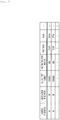
- Fig. 9 is a view showing the specific example of the feature value set. As shown by way of example in Fig. 9 , for example, 11 feature value sets are preset as the feature value sets, and the classification apparatus 10 may execute processes for all feature value sets or part of the feature value sets. In the example in Fig.
- the feature values related to the TCP flag are set as the target feature values to be extracted, and ratios of "URG”, “SYN”, “PSH”, “RST”, “ACK”, and "FIN” of the TCP flag in the transmission packet are extracted for each source IP address.
- the set name "OS” the type of an OS of the source which has transmitted an SYN packet to the darknet is extracted.
- any of "sa” indicative of compilation based on the source IP address, "da” indicative of compilation based on the destination IP address, "cli” indicative of compilation based on the IP address on the client side, and “srv” indicative of compilation based on the IP address on a server side is set.
- the IP address having a higher port number is used as the IP address on the client side in the case of "cli”
- the IP address having a lower port number is used as the IP address on the server side in the case of "srv”.
- the number of dimensions of the feature value to be extracted is also set. For example, in the set name "transmission flag”, "6" is set as the number of dimensions.
- the counting section 13d of the classification apparatus 10 counts the number of times of appearance of the pattern having the same combination of the classification results by using the frequent pattern mining method, and performs classification of bots (see (3) in Fig. 4 ).
- FIG. 10 is a view for explaining the process for classifying the bots of the same type by using the frequent pattern mining method by the classification apparatus according to the first embodiment.
- the counting section 13d searches for a large number of patterns which appear by using the frequent pattern mining method.
- Fig. 10 the example in Fig.
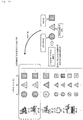
- a pattern having the label "1" of the feature value set A, the label “2" of the feature value set B, and the label “1” of the feature value set C is identified as a frequent pattern, and it is determined that IP addresses "A” and "B" corresponding to the frequent pattern are the IP addresses of bots of the same type.
- the classification apparatus 10 As features of the bot, it is possible to easily grasp that traffic is low, a large number of SYN packets are transmitted, and a communication protocol is telnet. That is, in the classification apparatus 10, it is possible to divide the feature value with aspects having meanings, and interpret the meaning of the label of each aspect. In addition, in the classification apparatus 10, it is possible to extract the frequent combination of features to grasp the entire picture of each bot with a plurality of labels.
- FIG. 11 a description will be given of examples of a bot having features.
- FIG. 11 is a view showing the example of the observed bot having features.
- Fig. 11 from the frequent pattern of each feature value set, it is possible to observe a bot which seems to be a mirai-based bot having such features that a large number of SYN packets are transmitted, the number of bytes of the transmission packet and the number of bytes of the reception packet are small, 23 and 2323 are used as the destination ports, and an OS is Linux (registered trademark) 2.4.x.
- the source port and the client port have features and the destination port has no feature, and hence it is possible to observe a bot having such features that the bot serves as a scanner which uses a fixed source port number, and scans various ports.
- the classification apparatus 10 by dividing the feature value from a plurality of viewpoints and performing the extraction, and using the frequent combination in the classification, interpretation of the meaning of each classification result and the meaning interpretation of the final classification result obtained by the combination of the classification results are facilitated. Consequently, in the classification apparatus 10, it is possible to determine, among unknown data, the type of specific data.
- the IP addresses which seem to belong to bots are narrowed down by using the condition that the IP address corresponds to the IP address from which the packet in which the control flag in the TCP header indicates "SYN" has been transmitted to the darknet. Accordingly, as shown by way of example in Fig. 13 , in the classification apparatus 10 according to the first embodiment, by utilizing information of the darknet which is space of an unused IP address and narrowing down the IP addresses which seem to belong to bots, it is possible to reduce the number of pieces of target traffic data to be processed to reduce a process load.
- Fig. 13 is a view for explaining a process for narrowing down the IP addresses which seem to belong to bots.
- Fig. 14 is a flowchart for explaining the processes by the classification apparatus according to the first embodiment.
- Step S101 when the acquisition section 13a of the classification apparatus 10 acquires the communication log including a plurality of pieces of traffic data in the predetermined time period (affirmative in Step S101), as the preprocessing performed on the acquired communication log, the acquisition section 13a executes the preprocessing for selecting only the traffic data having the IP address which satisfies the predetermined condition as a target to be processed (Step S102).
- the extraction section 13b extracts different types of feature values from the plurality of pieces of traffic data acquired by the acquisition section 13a (Step S103). Specifically, the extraction section 13b extracts the feature values specified by each preset feature value set.
- the classification section 13c performs clustering of the individual IP addresses based on the combination of the feature values extracted for each feature value set (Step S104), and assigns the label to each IP address based on the clustering result (Step S105).
- the counting section 13d uses a plurality of the classification results obtained by the classification by the classification section 13c to count the number of times of appearance of the combination of the same labels (Step S106), and outputs the frequent combination of the labels as data of the same group via the output section 12 (Step S107).
- the classification apparatus 10 acquires the communication log including the plurality of pieces of traffic data, and extracts different types of feature values from the plurality of pieces of traffic data. Subsequently, the classification apparatus 10 classifies the traffic data on a per IP address basis based on the extracted different types of feature values, and uses a plurality of the classification results to count the number of times of appearance of the pattern having the same combination of the classification results. Accordingly, the classification apparatus 10 can facilitate grasping of features of the data from the classification result.
- the classification is performed by dividing the feature value into a few feature values.
- the extraction of the feature value is performed from different viewpoints such as, e.g., a statistic of a packet size and the ratio of the TCP flag in the case of network traffic data, and the classification is performed.
- the classification apparatus 10 suppose that, when the classification is performed by using network traffic data as input information, the feature value is divided from the viewpoints of the TCP flag and the packet size, and the classification is performed. In that case, in the classification based on the TCP flag, the classification result such as a large number of SYNs or ACKs may be obtained and, in the classification based on the packet size, the result such as a large or small transmission amount may be obtained.
- the classification result is simplified and the interpretation of the reason for the result is facilitated.
- the classification results obtained by the feature value division are compiled, and data having the same combination of the classification results which has appeared the number of times equal to or greater than a threshold value ⁇ is outputted and is handled as data of the same group.
- different classification results are compiled and, in the case where a specific pattern has appeared in many pieces of data, it is not the case that the combination of the same classification results is obtained accidentally but it is possible to determine that the combination thereof is a feature common to the group.
- the classification result is the result which is easy to interpret, and it becomes possible to grasp overall features by combining the results.
- the combination of these features allows such an interpretation that this is a bot which performs scanning.
- the number of times of the division to increase the number of viewpoints for feature value extraction, it is possible to grasp the features of the classification more specifically.
- each apparatus shown in the drawings are functionally conceptual, and do not need to be physically configured as shown in the drawings. That is, the specific modes of separation and integration of the individual apparatuses are not limited to those shown in the drawings, and all or part of the apparatuses can be functionally or physically separated or integrated according to various loads or use situations based on an arbitrary unit.
- all or an arbitrary part of process functions performed in the individual apparatuses can be implemented by a CPU and a program analyzed and executed in the CPU, or can also be implemented as hardware which uses wired logic.
- Fig. 15 is a view showing a computer which executes a classification program.
- a computer 1000 has, e.g., a memory 1010, and a CPU 1020.
- the computer 1000 has a hard disk drive interface 1030, a disk drive interface 1040, a serial port interface 1050, a video adaptor 1060, and a network interface 1070. These sections are connected to each other by a bus 1080.
- the memory 1010 includes a ROM (Read Only Memory) 1011, and a RAM 1012.
- the ROM 1011 stores a boot program such as, e.g., a BIOS (Basic Input Output System).
- the hard disk drive interface 1030 is connected to a hard disk drive 1090.
- the disk drive interface 1040 is connected to a disk drive 1100.
- a detachable storage medium such as, e.g., a magnetic disk or an optical disk is inserted into the disk drive 1100.
- the serial port interface 1050 is connected to, e.g., a mouse 1051 and a keyboard 1052.
- the video adaptor 1060 is connected to, e.g., a display 1061.
- the hard disk drive 1090 stores, e.g., an OS 1091, an application program 1092, a program module 1093, and program data 1094. That is, the program for specifying each process of the classification apparatus 10 is implemented as the program module 1093 in which a code which can be executed by the computer is described.
- the program module 1093 is stored in, e.g., the hard disk drive 1090.
- the program module 1093 for executing the same process as that of the functional configuration in the apparatus is stored in the hard disk drive 1090.
- the hard disk drive 1090 may be replaced by an SSD (Solid State Drive).
- data used in the processes of the embodiment described above is stored as the program data 1094 in, e.g., the memory 1010 and the hard disk drive 1090.
- the CPU 1020 reads the program module 1093 and the program data 1094 stored in the memory 1010 and the hard disk drive 1090 into the RAM 1012 and executes the program module 1093 and the program data 1094 on an as needed basis.
- program module 1093 and the program data 1094 are not limited to the case where the program module 1093 and the program data 1094 are stored in the hard disk drive 1090, and may be stored in, e.g., a detachable storage medium and may be read by the CPU 1020 via the disk drive 1100 or the like.
- the program module 1093 and the program data 1094 may also be stored in another computer connected via a network or a WAN. Further, the program module 1093 and the program data 1094 may also be read from another computer by the CPU 1020 via the network interface 1070.
Landscapes
- Engineering & Computer Science (AREA)
- Theoretical Computer Science (AREA)
- General Engineering & Computer Science (AREA)
- Databases & Information Systems (AREA)
- Physics & Mathematics (AREA)
- General Physics & Mathematics (AREA)
- Data Mining & Analysis (AREA)
- Software Systems (AREA)
- Computer Security & Cryptography (AREA)
- Computing Systems (AREA)
- Computer Networks & Wireless Communication (AREA)
- Signal Processing (AREA)
- Artificial Intelligence (AREA)
- Evolutionary Computation (AREA)
- Mathematical Physics (AREA)
- Medical Informatics (AREA)
- Computer Vision & Pattern Recognition (AREA)
- Computer Hardware Design (AREA)
- Computational Linguistics (AREA)
- Data Exchanges In Wide-Area Networks (AREA)
- Information Retrieval, Db Structures And Fs Structures Therefor (AREA)
Abstract
Description
- The present invention relates to a classification apparatus and a classification method.
- There is a conventionally known technique for extracting multidimensional feature values from a plurality of pieces of data, classifying the individual pieces of data by using the extracted feature values, and analyzing the classification result. For example, as countermeasures against attacks which use a botnet constituted by infected terminals, multidimensional feature values are extracted from a plurality of pieces of traffic data included in a communication log, clustering of IP addresses is performed by using the extracted feature values, and the result of the clustering is analyzed.
- [NPL 1] Guofei Gu, Roberto Perdisci, Junjie Zhang, and Wenke Lee, "BotMiner: Clustering Analysis of Network Traffic for Protocol- and Structure-Independent Botnet Detection", 17th USENIX Security Symposium p139-p154, USENIX Association, 2008
- However, the conventional art has a problem where it is not easy to grasp features of data from the classification result. For example, in a method in which clustering of the IP addresses is performed by using the multidimensional feature values from the traffic data included in the communication log, there are cases where, as the number of dimensions of the extracted feature value increases, it is not possible to easily grasp the feature on which attention is focused when a cluster is formed. In addition, when the number of dimensions of the extracted feature value is large, there are cases where clustering is not performed appropriately.
- The present invention has been made in view of the above problem, and an object thereof is to facilitate grasping of features of data from a classification result.
- In order to solve the above problem and achieve the object, a classification apparatus of the present invention is a classification apparatus including: an acquisition section which acquires a plurality of pieces of data; an extraction section which extracts different types of feature values from the plurality of pieces of data acquired by the acquisition section; a classification section which classifies the data with a predetermined unit based on the different types of feature values extracted by the extraction section; and a counting section which uses a plurality of classification results obtained by the classification by the classification section to count the number of times of appearance of a pattern having the same combination of the classification results.
- In addition, a classification method of the present invention is a classification method executed by a classification apparatus, the classification method including: an acquisition step of acquiring a plurality of pieces of data; an extraction step of extracting different types of feature values from the plurality of pieces of data acquired by the acquisition step; a classification step of classifying the data with a predetermined unit based on the different types of feature values extracted by the extraction step; and a counting step of using a plurality of classification results obtained by the classification by the classification step to count the number of times of appearance of a pattern having the same combination of the classification results.
- According to the present invention, the effect of facilitating grasping of features of data from the classification result is achieved.
-
- [
Fig. 1 ]
Fig. 1 is a block diagram showing an example of the configuration of a classification apparatus according to a first embodiment. - [
Fig. 2 ]
Fig. 2 is a view showing an example of information stored in a communication log storage section. - [
Fig. 3 ]
Fig. 3 is a view showing an example of information stored in a classification result storage section. - [
Fig. 4 ]
Fig. 4 is a view for explaining an outline of processes by the classification apparatus according to the first embodiment. - [
Fig. 5 ]
Fig. 5 is a view for explaining preprocessing performed on a communication log by the classification apparatus according to the first embodiment. - [
Fig. 6 ]
Fig. 6 is a view for explaining a feature value extraction process by the classification apparatus according to the first embodiment. - [
Fig. 7 ]
Fig. 7 is a view for explaining the feature value extraction process by the classification apparatus according to the first embodiment. - [
Fig. 8 ]
Fig. 8 is a view for explaining the feature value extraction process by the classification apparatus according to the first embodiment. - [
Fig. 9 ]
Fig. 9 is a view showing a specific example of a feature value set. - [
Fig. 10 ]
Fig. 10 is a view for explaining a process for classifying bots of the same type by using a frequent pattern mining method by the classification apparatus according to the first embodiment. - [
Fig. 11 ]
Fig. 11 is a view showing an example of an observed bot having features. - [
Fig. 12 ]
Fig. 12 is a view showing an example of an observed bot having features. - [
Fig. 13 ]
Fig. 13 is a view for explaining a process for narrowing down IP addresses which seem to belong to bots. - [
Fig. 14 ]
Fig. 14 is a flowchart for explaining processes by the classification apparatus according to the first embodiment. - [
Fig. 15 ]
Fig. 15 is a view showing a computer which executes a classification program. - Hereinbelow, an embodiment of a classification apparatus and a classification method according to the present application will be described in detail based on the drawings. Note that the classification apparatus and the classification method according to the present application are not limited by the embodiment. For example, a description will be made by using, as an example, communication data as target data to be analyzed in the following embodiment, but the target data to be analyzed is not limited thereto, and any data may be used as the target data to be analyzed.
- In the following embodiment, the configuration of a classification apparatus according to a first embodiment and the flow of processes in the classification apparatus will be described in this order, and an effect obtained by the first embodiment will be described lastly.
- First, by using
Fig. 1 , a description will be given of the configuration of aclassification apparatus 10.Fig. 1 is a block diagram showing an example of the configuration of the classification apparatus according to the first embodiment. As shown inFig. 1 , theclassification apparatus 10 has aninput section 11, anoutput section 12, acontrol section 13, and a storage section 14. Hereinafter, a description will be given of processes of individual sections of theclassification apparatus 10. - The
input section 11 is implemented by using an input device such as a keyboard or a mouse, and inputs various pieces of instruction information into thecontrol section 13 in response to an input operation by an operator. Theoutput section 12 is implemented by a display apparatus such as a liquid crystal display, a printing apparatus such as a printer, an information communication apparatus, or a speaker, and outputs, e.g., a frequent pattern described later and the like to the operator. - The storage section 14 stores data and programs required for various processes by the
control section 13, and has a communicationlog storage section 14a and a classificationresult storage section 14b which are particularly closely related to the present invention. An example of the storage section 14 includes a semiconductor memory device such as a RAM (Random Access Memory) or a flash memory, or a storage device such as a hard disk or an optical disk. - The communication
log storage section 14a stores a communication log acquired by anacquisition section 13a described later. For example, as the communication log, communication logs having various forms such as an xFlow, a Proxy log, and a Firewall log are used. Note that, in the following example, a description will be made by mainly using the xFlow serving as flow information of a network as an example. The xFlow includes a source IP address, a destination IP address, a source port number, a destination port number, a protocol, and a flag. - Herein, by using
Fig. 2 , a description will be given of an example of information stored in the communicationlog storage section 14a.Fig. 2 is a view showing an example of information stored in the communication log storage section. As shown by way of example inFig. 2 , the communicationlog storage section 14a stores "source IP address" indicative of an IP address of a source, "destination IP address" indicative of an IP address of a destination, "source port number" indicative of a port number of a source, "destination port number" indicative of a port number of a destination, "protocol" indicative of a communication protocol, and "flag" indicative of a control flag in a TCP header. - The classification
result storage section 14b stores a classification result obtained by classification by aclassification section 13c described later. For example, as shown by way of example inFig. 3 , the classificationresult storage section 14b stores labels of the classification results of a feature value set A, a feature value set B, a feature value set C ... for each IP address. Herein, the feature value set denotes a combination of preset feature values to be extracted.Fig. 3 is a view showing an example of information stored in the classification result storage section. - A description will be made by using the example in
Fig. 3 . The classificationresult storage section 14b stores the label "1" of the feature value set A, the label "2" of the feature value set B, and the label "1" of the feature value set C for an IP address "A". In addition, the classificationresult storage section 14b stores the label "1" of the feature value set A, the label "2" of the feature value set B, and the label "1" of the feature value set C for an IP address "B". Further, the classificationresult storage section 14b stores the label "2" of the feature value set A, the label "1" of the feature value set B, and the label "3" of the feature value set C for an IP address "C". - The
control section 13 has an internal memory for storing programs and required data in which procedures of various processes are specified and executes the various processes by using the programs and the required data and, thecontrol section 13 has theacquisition section 13a, anextraction section 13b, theclassification section 13c, and a counting section 13d which are particularly closely related to the present invention. Herein, thecontrol section 13 is an electronic circuit such as a CPU (Central Processing Unit) or an MPU (Micro Processing Unit), or an integrated circuit such as an ASIC (Application Specific Integrated Circuit) or an FPGA (Field Programmable Gate Array). - The
acquisition section 13a acquires a communication log including a plurality of pieces of traffic data. Specifically, when theacquisition section 13a acquires the communication log including the plurality of pieces of traffic data in a predetermined time period, theacquisition section 13a stores the traffic data included in the acquired communication log in the communicationlog storage section 14a. Note that theacquisition section 13a may acquire the communication log in real time, or may also perform a batch process for segmenting the plurality of pieces of traffic data into traffic data groups in a predetermined time period and store the traffic data groups in the communicationlog storage section 14a. - In addition, as preprocessing performed on the acquired communication log, the
acquisition section 13a may store only traffic data having the IP address which satisfies a predetermined condition in the communicationlog storage section 14a as a target to be processed. For example, theacquisition section 13a may store, in the communicationlog storage section 14a, only the traffic data having, as a source, an IP address which satisfies a predetermined condition (1) that a packet in which a control flag in a TCP header indicates "SYN" has been transmitted to a darknet from the IP address, and a predetermined condition (2) that 20 or more flows in one-way communication have been observed during a predetermined time period at the IP address. In addition, even in the case where one of the predetermined conditions (1) and (2) described above is satisfied, theacquisition section 13a may store the traffic data having the corresponding IP address as the source in the communicationlog storage section 14a. - The
extraction section 13b extracts different types of feature values from a plurality of pieces of traffic data acquired by theacquisition section 13a. Specifically, theextraction section 13b extracts the feature values specified by each preset feature value set. - For example, from among feature values related to the number of bytes sent of traffic data, the number of bytes received of traffic data, a transmission flag of traffic data, a reception flag of traffic data, a destination port number of traffic data, and a source port number of traffic data, the
extraction section 13b extracts two or more types of the feature values as the different types of feature values. - The
classification section 13c classifies the traffic data on a per IP address basis based on the different types of feature values extracted by theextraction section 13b. Specifically, theclassification section 13c performs clustering of the individual IP addresses based on a combination of the feature values extracted for each feature value set, assigns a label to each IP address based on the clustering result, and stores the IP address in the classificationresult storage section 14b. In addition, theclassification section 13c may classify the traffic data on a per IP address basis by using, e.g., an unsupervised machine learning method. - The counting section 13d uses a plurality of classification results obtained by the classification by the
classification section 13c to count the number of times of appearance of a pattern having the same combination of the classification results. In addition, the counting section 13d counts the number of times of appearance of the pattern having the same combination of the classification results, and outputs a pattern which satisfies a predetermined condition. Specifically, the counting section 13d uses a plurality of the classification results obtained by the classification by theclassification section 13c to count the number of times of appearance of the pattern having the same combination of the classification results and, in the case where the number of times of appearance of the pattern having the same combination of the classification results is equal to or greater than a threshold value, the counting section 13d outputs the pattern via theoutput section 12. For example, the counting section 13d may count the number of times of appearance of the pattern by using a frequent pattern mining method. - Herein, by using an example in
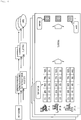
Fig. 4 , a description will be given of an outline of processes by theclassification apparatus 10 according to the first embodiment.Fig. 4 is a view for explaining the outline of the processes by the classification apparatus according to the first embodiment. As shown by way of example inFig. 4 , theacquisition section 13a of theclassification apparatus 10 acquires the communication log such as the xFlow and, as the preprocessing performed on the acquired communication log, selects the traffic data having the IP address which satisfies the predetermined condition as the target traffic data to be processed (see (1) inFig. 4 ) . - Herein, by using
Fig. 5 , a description will be given of an example of the preprocessing performed on the communication log.Fig. 5 is a view for explaining the preprocessing performed on the communication log by the classification apparatus according to the first embodiment. As shown by way of example inFig. 5 , for example, theacquisition section 13a uses only the flow (traffic data) having, as the source, the IP address from which the packet in which the control flag in the TCP header indicates "SYN" has been transmitted to the darknet and at which 20 or more flows in one-way communication have been observed during the predetermined time period, which are the predetermined conditions. - Returning to the description of
Fig. 4 , theextraction section 13b of theclassification apparatus 10 extracts the feature values specified by the preset feature value sets A to C. Herein, theextraction section 13b may perform the processes for extracting the feature values specified by the feature value sets A to C in parallel, or may perform the processes for extracting the feature values specified by the feature value sets A to C sequentially. Subsequently, theclassification section 13c performs clustering of the individual IP addresses based on the combination of the feature values extracted for each of the feature value sets A to C, and assigns the label to each IP address based on the clustering result (see (2) inFig. 4 ). - Herein, by using examples in
Figs. 6 to 8 , a description will be given of a feature value extraction process by theclassification apparatus 10.Figs. 6 to 8 are views for explaining the feature value extraction process by the classification apparatus according to the first embodiment. First, by usingFig. 6 , a description will be given of the process for extracting the feature values specified by the feature value set A. In the following description, suppose that the feature values related to traffic are set as the target feature values to be extracted in the feature value set A. - As shown by way of example in
Fig. 6 , theextraction section 13b extracts, for each source IP address, "maximum", "minimum", "average", and "variance" of the number of bytes per packet as the feature values related to the traffic. For example, as shown by way of example inFig. 6 , as the feature values of a source IP: A, theextraction section 13b extracts "59.0" bytes as "maximum" of the number of bytes per packet, extracts "40.0" bytes as "minimum" thereof, extracts "41.5" bytes as "average" thereof, and extracts "4.04" bytes as "variance" thereof. - Subsequently, the
classification section 13c performs clustering of the individual source IP addresses, and assigns the label to each source IP address based on the clustering result. For example, theclassification section 13c performs clustering of the source IP addresses to classify the source IP addresses into a cluster of the source IP addresses having low traffic and a cluster of the source IP addresses having high traffic, and assigns the label "2" to the source IP address having high traffic and assigns the label "1" to the source IP address having low traffic. - Next, by using
Fig. 7 , a description will be given of the process for extracting the feature values specified by the feature value set B. In the following description, suppose that the feature values related to the TCP flag are set as the target feature values to be extracted in the feature value set B. - As shown by way of example in
Fig. 7 , theextraction section 13b extracts, for each source IP address, ratios of "URG", "SYN", "PSH", "RST", "ACK", and "FIN" of the TCP flag in a transmission packet as the feature values related to the TCP flag. For example, as shown by way of example inFig. 7 , as the feature values of the source IP: A, theextraction section 13b extracts "0" as the ratio of "URG", extracts "0.08" as the ratio of "ACK", extracts "0.03" as the ratio of "PSH", extracts "0" as the ratio of "RST", extracts "0.91" as the ratio of "SYN", and extracts "0.01" as the ratio of "FIN". - Subsequently, the
classification section 13c performs clustering of the individual source IP addresses, and assigns the label to each source IP address based on the clustering result. For example, theclassification section 13c performs clustering of the source IP addresses to classify the source IP addresses into a cluster of the source IP addresses each having a large number of "ACKs" of the TCP flag and a cluster of the source IP addresses each having a large number of "SYNs" of the TCP flag, and assigns the label "1" to the source IP address having a large number of "ACKs" and assigns the label "2" to the source IP address having a large number of "SYNs". - Next, by using
Fig. 8 , a description will be given of the process for extracting the feature values specified by the feature value set C. In the following description, suppose that the feature values related to a port are set as the target feature values to be extracted in the feature value set C. As shown by way of example inFig. 8 , theextraction section 13b extracts, for each IP address on a client side, minimum (0%), 25%, mean (50%), 75%, and maximum (100%) source port numbers when the source port numbers used during the packet transmission are arranged in ascending order as the feature values related to the port. - For example, as shown by way of example in
Fig. 8 , as the feature values of the IP address on the client side: A, theextraction section 13b extracts "23" as the "0%" port number, extracts "23" as the "25%" port number, extracts "23" as the "50%" port number, extracts "23" as the "75%" port number, and extracts "23" as the "100%" port number. This means that a destination port number "23" has been always used during the packet transmission. - Subsequently, the
classification section 13c performs clustering of the individual IP addresses on the client side, and assigns the label to each IP address on the client side. For example, theclassification section 13c performs clustering of the individual IP addresses on the client side according to the tendency of a used port number. - Note that the description has been made by using the three feature value sets A to C as examples in the examples in
Figs. 6 to 8 described above, but the feature value set is not limited thereto. Herein, a description will be given of a specific example of the feature value set by using an example inFig. 9. Fig. 9 is a view showing the specific example of the feature value set. As shown by way of example inFig. 9 , for example, 11 feature value sets are preset as the feature value sets, and theclassification apparatus 10 may execute processes for all feature value sets or part of the feature value sets. In the example inFig. 9 , as set names of the feature value sets, "transmission flag", "reception flag", "transmission amount", "reception amount", "transmission amount 2", "reception amount 2", "source port", "client port", "destination port", "server port", and "OS" are set. - For example, in the set name "transmission flag", the feature values related to the TCP flag are set as the target feature values to be extracted, and ratios of "URG", "SYN", "PSH", "RST", "ACK", and "FIN" of the TCP flag in the transmission packet are extracted for each source IP address. In the set name "OS", the type of an OS of the source which has transmitted an SYN packet to the darknet is extracted.
- As a compilation unit, any of "sa" indicative of compilation based on the source IP address, "da" indicative of compilation based on the destination IP address, "cli" indicative of compilation based on the IP address on the client side, and "srv" indicative of compilation based on the IP address on a server side is set. Note that the IP address having a higher port number is used as the IP address on the client side in the case of "cli", and the IP address having a lower port number is used as the IP address on the server side in the case of "srv". In addition, the number of dimensions of the feature value to be extracted is also set. For example, in the set name "transmission flag", "6" is set as the number of dimensions.
- Returning to the description of
Fig. 4 , the counting section 13d of theclassification apparatus 10 counts the number of times of appearance of the pattern having the same combination of the classification results by using the frequent pattern mining method, and performs classification of bots (see (3) inFig. 4 ). - Herein, by using
Fig. 10 , a description will be given of a process for classifying bots of the same type by using the frequent pattern mining method.Fig. 10 is a view for explaining the process for classifying the bots of the same type by using the frequent pattern mining method by the classification apparatus according to the first embodiment. As shown by way of example inFig. 10 , the counting section 13d searches for a large number of patterns which appear by using the frequent pattern mining method. In the example inFig. 10 , a pattern having the label "1" of the feature value set A, the label "2" of the feature value set B, and the label "1" of the feature value set C is identified as a frequent pattern, and it is determined that IP addresses "A" and "B" corresponding to the frequent pattern are the IP addresses of bots of the same type. - As features of the bot, it is possible to easily grasp that traffic is low, a large number of SYN packets are transmitted, and a communication protocol is telnet. That is, in the
classification apparatus 10, it is possible to divide the feature value with aspects having meanings, and interpret the meaning of the label of each aspect. In addition, in theclassification apparatus 10, it is possible to extract the frequent combination of features to grasp the entire picture of each bot with a plurality of labels. - Herein, by using
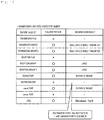
Fig. 11 andFig. 12 , a description will be given of examples of a bot having features. Each ofFigs. 11 and12 is a view showing the example of the observed bot having features. As shown by way of example inFig. 11 , from the frequent pattern of each feature value set, it is possible to observe a bot which seems to be a mirai-based bot having such features that a large number of SYN packets are transmitted, the number of bytes of the transmission packet and the number of bytes of the reception packet are small, 23 and 2323 are used as the destination ports, and an OS is Linux (registered trademark) 2.4.x. - In addition, as shown by way of example in
Fig. 12 , judging from the frequent pattern of each feature value set, the source port and the client port have features and the destination port has no feature, and hence it is possible to observe a bot having such features that the bot serves as a scanner which uses a fixed source port number, and scans various ports. - That is, in the
classification apparatus 10, by dividing the feature value from a plurality of viewpoints and performing the extraction, and using the frequent combination in the classification, interpretation of the meaning of each classification result and the meaning interpretation of the final classification result obtained by the combination of the classification results are facilitated. Consequently, in theclassification apparatus 10, it is possible to determine, among unknown data, the type of specific data. - In addition, in the
classification apparatus 10 according to the first embodiment, the IP addresses which seem to belong to bots are narrowed down by using the condition that the IP address corresponds to the IP address from which the packet in which the control flag in the TCP header indicates "SYN" has been transmitted to the darknet. Accordingly, as shown by way of example inFig. 13 , in theclassification apparatus 10 according to the first embodiment, by utilizing information of the darknet which is space of an unused IP address and narrowing down the IP addresses which seem to belong to bots, it is possible to reduce the number of pieces of target traffic data to be processed to reduce a process load.Fig. 13 is a view for explaining a process for narrowing down the IP addresses which seem to belong to bots. - Next, by using
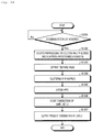
Fig. 14 , a description will be given of the flow of processes of theclassification apparatus 10 according to the first embodiment.Fig. 14 is a flowchart for explaining the processes by the classification apparatus according to the first embodiment. - As shown in
Fig. 14 , when theacquisition section 13a of theclassification apparatus 10 acquires the communication log including a plurality of pieces of traffic data in the predetermined time period (affirmative in Step S101), as the preprocessing performed on the acquired communication log, theacquisition section 13a executes the preprocessing for selecting only the traffic data having the IP address which satisfies the predetermined condition as a target to be processed (Step S102). - Then, the
extraction section 13b extracts different types of feature values from the plurality of pieces of traffic data acquired by theacquisition section 13a (Step S103). Specifically, theextraction section 13b extracts the feature values specified by each preset feature value set. - Subsequently, the
classification section 13c performs clustering of the individual IP addresses based on the combination of the feature values extracted for each feature value set (Step S104), and assigns the label to each IP address based on the clustering result (Step S105). - Then, the counting section 13d uses a plurality of the classification results obtained by the classification by the
classification section 13c to count the number of times of appearance of the combination of the same labels (Step S106), and outputs the frequent combination of the labels as data of the same group via the output section 12 (Step S107). - Thus, the
classification apparatus 10 according to the first embodiment acquires the communication log including the plurality of pieces of traffic data, and extracts different types of feature values from the plurality of pieces of traffic data. Subsequently, theclassification apparatus 10 classifies the traffic data on a per IP address basis based on the extracted different types of feature values, and uses a plurality of the classification results to count the number of times of appearance of the pattern having the same combination of the classification results. Accordingly, theclassification apparatus 10 can facilitate grasping of features of the data from the classification result. - Thus, in the
classification apparatus 10 according to the first embodiment, the classification is performed by dividing the feature value into a few feature values. In the division, the extraction of the feature value is performed from different viewpoints such as, e.g., a statistic of a packet size and the ratio of the TCP flag in the case of network traffic data, and the classification is performed. By performing the classification in this manner, it is possible to obtain the classification result corresponding to the inputted feature value, and the interpretation of the meaning of the result is improved. - For example, in the
classification apparatus 10, suppose that, when the classification is performed by using network traffic data as input information, the feature value is divided from the viewpoints of the TCP flag and the packet size, and the classification is performed. In that case, in the classification based on the TCP flag, the classification result such as a large number of SYNs or ACKs may be obtained and, in the classification based on the packet size, the result such as a large or small transmission amount may be obtained. Thus, by dividing the feature value according to the viewpoint and performing the classification by using a few feature values as the input information, the classification result is simplified and the interpretation of the reason for the result is facilitated. - In addition, in the
classification apparatus 10, the classification results obtained by the feature value division are compiled, and data having the same combination of the classification results which has appeared the number of times equal to or greater than a threshold value θ is outputted and is handled as data of the same group. Further, in theclassification apparatus 10, different classification results are compiled and, in the case where a specific pattern has appeared in many pieces of data, it is not the case that the combination of the same classification results is obtained accidentally but it is possible to determine that the combination thereof is a feature common to the group. The classification result is the result which is easy to interpret, and it becomes possible to grasp overall features by combining the results. - For example, in the example of the classification based on the TCP flag, in the case where a combination of a small number of SYNs and a small transmission amount is extracted, the combination of these features allows such an interpretation that this is a bot which performs scanning. In addition, by increasing the number of times of the division to increase the number of viewpoints for feature value extraction, it is possible to grasp the features of the classification more specifically.
- The constituent elements of each apparatus shown in the drawings are functionally conceptual, and do not need to be physically configured as shown in the drawings. That is, the specific modes of separation and integration of the individual apparatuses are not limited to those shown in the drawings, and all or part of the apparatuses can be functionally or physically separated or integrated according to various loads or use situations based on an arbitrary unit. In addition, all or an arbitrary part of process functions performed in the individual apparatuses can be implemented by a CPU and a program analyzed and executed in the CPU, or can also be implemented as hardware which uses wired logic.
- Further, among the processes described in the present embodiment, all or part of the processes described as the processes which are performed automatically can be performed manually, or all or part of the processes described as the processes which are performed manually can be performed automatically by a known method. In addition, information including the process procedure, the control procedure, the specific names, various pieces of data, and parameters described or shown in the above specification or the drawings can be arbitrarily changed unless otherwise indicated.
-
Fig. 15 is a view showing a computer which executes a classification program. Acomputer 1000 has, e.g., amemory 1010, and aCPU 1020. In addition, thecomputer 1000 has a harddisk drive interface 1030, adisk drive interface 1040, aserial port interface 1050, avideo adaptor 1060, and anetwork interface 1070. These sections are connected to each other by a bus 1080. - The
memory 1010 includes a ROM (Read Only Memory) 1011, and aRAM 1012. TheROM 1011 stores a boot program such as, e.g., a BIOS (Basic Input Output System). The harddisk drive interface 1030 is connected to ahard disk drive 1090. Thedisk drive interface 1040 is connected to adisk drive 1100. A detachable storage medium such as, e.g., a magnetic disk or an optical disk is inserted into thedisk drive 1100. Theserial port interface 1050 is connected to, e.g., amouse 1051 and akeyboard 1052. Thevideo adaptor 1060 is connected to, e.g., adisplay 1061. - The
hard disk drive 1090 stores, e.g., anOS 1091, anapplication program 1092, aprogram module 1093, andprogram data 1094. That is, the program for specifying each process of theclassification apparatus 10 is implemented as theprogram module 1093 in which a code which can be executed by the computer is described. Theprogram module 1093 is stored in, e.g., thehard disk drive 1090. For example, theprogram module 1093 for executing the same process as that of the functional configuration in the apparatus is stored in thehard disk drive 1090. Note that thehard disk drive 1090 may be replaced by an SSD (Solid State Drive). - In addition, data used in the processes of the embodiment described above is stored as the
program data 1094 in, e.g., thememory 1010 and thehard disk drive 1090. TheCPU 1020 reads theprogram module 1093 and theprogram data 1094 stored in thememory 1010 and thehard disk drive 1090 into theRAM 1012 and executes theprogram module 1093 and theprogram data 1094 on an as needed basis. - Note that the
program module 1093 and theprogram data 1094 are not limited to the case where theprogram module 1093 and theprogram data 1094 are stored in thehard disk drive 1090, and may be stored in, e.g., a detachable storage medium and may be read by theCPU 1020 via thedisk drive 1100 or the like. Alternatively, theprogram module 1093 and theprogram data 1094 may also be stored in another computer connected via a network or a WAN. Further, theprogram module 1093 and theprogram data 1094 may also be read from another computer by theCPU 1020 via thenetwork interface 1070. -
- 10
- Classification apparatus
- 11
- Input section
- 12
- Output section
- 13
- Control section
- 13a
- Acquisition section
- 13b
- Extraction section
- 13c
- Classification section
- 13d
- Counting section
- 14
- Storage section
- 14a
- Communication log storage section
- 14b
- Classification result storage section
Claims (7)
- A classification apparatus comprising:an acquisition section which acquires a plurality of pieces of data;an extraction section which extracts different types of feature values from the plurality of pieces of data acquired by the acquisition section;a classification section which classifies the data with a predetermined unit based on the different types of feature values extracted by the extraction section; anda counting section which uses a plurality of classification results obtained by the classification by the classification section to count the number of times of appearance of a pattern having the same combination of the classification results.
- The classification apparatus according to Claim 1, wherein the counting section counts the number of times of appearance of the pattern having the same combination of the classification results, and outputs a pattern which satisfies a predetermined condition.
- The classification apparatus according to Claim 1, wherein
the acquisition section acquires a communication log including a plurality of pieces of traffic data, and
the extraction section extracts, as the different types of feature values, two or more types of feature values from among feature values related to the number of bytes sent of the traffic data, the number of bytes received of the traffic data, a transmission flag of the traffic data, a reception flag of the traffic data, a destination port number of the traffic data, and a source port number of the traffic data. - The classification apparatus according to Claim 1, wherein the classification section classifies the data by using an unsupervised machine learning method.
- The classification apparatus according to Claim 1, wherein the counting section counts the number of times of appearance of the pattern by using a frequent pattern mining method.
- The classification apparatus according to Claim 1, wherein the acquisition section selects only data which satisfies a predetermined condition as a target to be processed.
- A classification method executed by a classification apparatus, the classification method comprising:an acquisition step of acquiring a plurality of pieces of data;an extraction step of extracting different types of feature values from the plurality of pieces of data acquired by the acquisition step;a classification step of classifying the data with a predetermined unit based on the different types of feature values extracted by the extraction step; anda counting step of using a plurality of classification results obtained by the classification by the classification step to count the number of times of appearance of a pattern having the same combination of the classification results.
Applications Claiming Priority (2)
| Application Number | Priority Date | Filing Date | Title |
|---|---|---|---|
| JP2018033888A JP7013940B2 (en) | 2018-02-27 | 2018-02-27 | Classification device and classification method |
| PCT/JP2019/006881 WO2019167847A1 (en) | 2018-02-27 | 2019-02-22 | Classification device and classification method |
Publications (3)
| Publication Number | Publication Date |
|---|---|
| EP3745324A1 true EP3745324A1 (en) | 2020-12-02 |
| EP3745324A4 EP3745324A4 (en) | 2021-10-20 |
| EP3745324B1 EP3745324B1 (en) | 2022-08-31 |
Family
ID=67805042
Family Applications (1)
| Application Number | Title | Priority Date | Filing Date |
|---|---|---|---|
| EP19760201.4A Active EP3745324B1 (en) | 2018-02-27 | 2019-02-22 | Classification device and classification method |
Country Status (4)
| Country | Link |
|---|---|
| US (1) | US12204560B2 (en) |
| EP (1) | EP3745324B1 (en) |
| JP (1) | JP7013940B2 (en) |
| WO (1) | WO2019167847A1 (en) |
Families Citing this family (6)
| Publication number | Priority date | Publication date | Assignee | Title |
|---|---|---|---|---|
| CN112422513B (en) * | 2020-10-26 | 2021-10-26 | 浙江大学 | Anomaly detection and attack initiator analysis system based on network traffic message |
| CN114489672B (en) * | 2022-01-27 | 2025-03-21 | 深圳Tcl新技术有限公司 | Boot acceleration method, device, electronic device and storage medium |
| CN114511040A (en) * | 2022-03-31 | 2022-05-17 | 北京邮电大学 | Network traffic classification method and device based on AP clustering |
| CN114741577B (en) * | 2022-04-27 | 2023-08-11 | 广域铭岛数字科技有限公司 | Service data management method, system, electronic equipment and readable storage medium |
| CN117112783A (en) * | 2023-07-11 | 2023-11-24 | 中国银行股份有限公司 | User classification methods, devices, computer equipment, storage media and program products |
| CN117729137A (en) * | 2024-02-08 | 2024-03-19 | 金数信息科技(苏州)有限公司 | A method, device and equipment for generating characteristics of network traffic data |
Family Cites Families (5)
| Publication number | Priority date | Publication date | Assignee | Title |
|---|---|---|---|---|
| US7475405B2 (en) * | 2000-09-06 | 2009-01-06 | International Business Machines Corporation | Method and system for detecting unusual events and application thereof in computer intrusion detection |
| US20120254333A1 (en) * | 2010-01-07 | 2012-10-04 | Rajarathnam Chandramouli | Automated detection of deception in short and multilingual electronic messages |
| US8805839B2 (en) * | 2010-04-07 | 2014-08-12 | Microsoft Corporation | Analysis of computer network activity by successively removing accepted types of access events |
| US10536357B2 (en) * | 2015-06-05 | 2020-01-14 | Cisco Technology, Inc. | Late data detection in data center |
| US9699205B2 (en) * | 2015-08-31 | 2017-07-04 | Splunk Inc. | Network security system |
-
2018
- 2018-02-27 JP JP2018033888A patent/JP7013940B2/en active Active
-
2019
- 2019-02-22 EP EP19760201.4A patent/EP3745324B1/en active Active
- 2019-02-22 WO PCT/JP2019/006881 patent/WO2019167847A1/en not_active Ceased
- 2019-02-22 US US16/975,687 patent/US12204560B2/en active Active
Also Published As
| Publication number | Publication date |
|---|---|
| WO2019167847A1 (en) | 2019-09-06 |
| JP2019149051A (en) | 2019-09-05 |
| US20200401608A1 (en) | 2020-12-24 |
| US12204560B2 (en) | 2025-01-21 |
| JP7013940B2 (en) | 2022-02-01 |
| EP3745324A4 (en) | 2021-10-20 |
| EP3745324B1 (en) | 2022-08-31 |
Similar Documents
| Publication | Publication Date | Title |
|---|---|---|
| US12204560B2 (en) | Classification device and classification method | |
| US8010685B2 (en) | Method and apparatus for content classification | |
| EP3145130B1 (en) | Network system, communication control method, and communication control program | |
| JP6159018B2 (en) | Extraction condition determination method, communication monitoring system, extraction condition determination apparatus, and extraction condition determination program | |
| CN105871619B (en) | A kind of flow load type detection method based on n-gram multiple features | |
| US11863584B2 (en) | Infection spread attack detection device, attack origin specification method, and program | |
| CN113114671B (en) | Cloud data security identification and classification method | |
| CN110611640A (en) | DNS protocol hidden channel detection method based on random forest | |
| JP2006279930A (en) | Method and device for detecting and blocking unauthorized access | |
| CN113518042A (en) | Data processing method, device, equipment and storage medium | |
| CN110691072A (en) | Distributed port scanning method, device, medium and electronic equipment | |
| CN112800424A (en) | Botnet malicious traffic monitoring method based on random forest | |
| JP6592196B2 (en) | Malignant event detection apparatus, malignant event detection method, and malignant event detection program | |
| Boukhtouta et al. | Towards fingerprinting malicious traffic | |
| JP6708575B2 (en) | Classification device, classification method, and classification program | |
| US10680959B2 (en) | Metadata extraction | |
| JP7239016B2 (en) | Sorting device, sorting method, sorting program | |
| US11997121B2 (en) | Detection device, detection method, and detection program | |
| CN112929364A (en) | Data leakage detection method and system based on ICMP tunnel analysis | |
| CN107222343A (en) | Dedicated network stream sorting technique based on SVMs | |
| Ogonowski et al. | Preliminary study on artificial intelligence methods for cybersecurity threat detection in computer networks based on raw data packets | |
| US11863416B2 (en) | Imparting device, imparting method, and imparting program | |
| Sija et al. | Automatic Payload Signature Generation for Accurate Identification of Internet Applications and Application Services. | |
| CN117714326A (en) | VPN flow identification method, VPN identification model training method and equipment | |
| CN114938290A (en) | Information detection method, device and equipment |
Legal Events
| Date | Code | Title | Description |
|---|---|---|---|
| STAA | Information on the status of an ep patent application or granted ep patent |
Free format text: STATUS: THE INTERNATIONAL PUBLICATION HAS BEEN MADE |
|
| PUAI | Public reference made under article 153(3) epc to a published international application that has entered the european phase |
Free format text: ORIGINAL CODE: 0009012 |
|
| STAA | Information on the status of an ep patent application or granted ep patent |
Free format text: STATUS: REQUEST FOR EXAMINATION WAS MADE |
|
| 17P | Request for examination filed |
Effective date: 20200824 |
|
| AK | Designated contracting states |
Kind code of ref document: A1 Designated state(s): AL AT BE BG CH CY CZ DE DK EE ES FI FR GB GR HR HU IE IS IT LI LT LU LV MC MK MT NL NO PL PT RO RS SE SI SK SM TR |
|
| AX | Request for extension of the european patent |
Extension state: BA ME |
|
| DAV | Request for validation of the european patent (deleted) | ||
| DAX | Request for extension of the european patent (deleted) | ||
| A4 | Supplementary search report drawn up and despatched |
Effective date: 20210922 |
|
| RIC1 | Information provided on ipc code assigned before grant |
Ipc: G06F 16/00 20190101ALI20210916BHEP Ipc: G06N 5/02 20060101ALI20210916BHEP Ipc: H04L 29/06 20060101ALI20210916BHEP Ipc: G06N 20/00 20190101AFI20210916BHEP |
|
| REG | Reference to a national code |
Ref country code: DE Ref legal event code: R079 Ref document number: 602019019023 Country of ref document: DE Free format text: PREVIOUS MAIN CLASS: G06N0020000000 Ipc: H04L0009400000 |
|
| RIC1 | Information provided on ipc code assigned before grant |
Ipc: G06F 16/00 20190101ALI20220325BHEP Ipc: G06N 5/02 20060101ALI20220325BHEP Ipc: G06N 20/00 20190101ALI20220325BHEP Ipc: H04L 9/40 20220101AFI20220325BHEP |
|
| GRAP | Despatch of communication of intention to grant a patent |
Free format text: ORIGINAL CODE: EPIDOSNIGR1 |
|
| STAA | Information on the status of an ep patent application or granted ep patent |
Free format text: STATUS: GRANT OF PATENT IS INTENDED |
|
| INTG | Intention to grant announced |
Effective date: 20220518 |
|
| GRAS | Grant fee paid |
Free format text: ORIGINAL CODE: EPIDOSNIGR3 |
|
| GRAA | (expected) grant |
Free format text: ORIGINAL CODE: 0009210 |
|
| STAA | Information on the status of an ep patent application or granted ep patent |
Free format text: STATUS: THE PATENT HAS BEEN GRANTED |
|
| AK | Designated contracting states |
Kind code of ref document: B1 Designated state(s): AL AT BE BG CH CY CZ DE DK EE ES FI FR GB GR HR HU IE IS IT LI LT LU LV MC MK MT NL NO PL PT RO RS SE SI SK SM TR |
|
| REG | Reference to a national code |
Ref country code: CH Ref legal event code: EP Ref country code: GB Ref legal event code: FG4D |
|
| REG | Reference to a national code |
Ref country code: AT Ref legal event code: REF Ref document number: 1516118 Country of ref document: AT Kind code of ref document: T Effective date: 20220915 Ref country code: DE Ref legal event code: R096 Ref document number: 602019019023 Country of ref document: DE |
|
| REG | Reference to a national code |
Ref country code: IE Ref legal event code: FG4D |
|
| REG | Reference to a national code |
Ref country code: SE Ref legal event code: TRGR |
|
| REG | Reference to a national code |
Ref country code: LT Ref legal event code: MG9D |
|
| REG | Reference to a national code |
Ref country code: NL Ref legal event code: MP Effective date: 20220831 |
|
| PG25 | Lapsed in a contracting state [announced via postgrant information from national office to epo] |
Ref country code: RS Free format text: LAPSE BECAUSE OF FAILURE TO SUBMIT A TRANSLATION OF THE DESCRIPTION OR TO PAY THE FEE WITHIN THE PRESCRIBED TIME-LIMIT Effective date: 20220831 Ref country code: NO Free format text: LAPSE BECAUSE OF FAILURE TO SUBMIT A TRANSLATION OF THE DESCRIPTION OR TO PAY THE FEE WITHIN THE PRESCRIBED TIME-LIMIT Effective date: 20221130 Ref country code: LV Free format text: LAPSE BECAUSE OF FAILURE TO SUBMIT A TRANSLATION OF THE DESCRIPTION OR TO PAY THE FEE WITHIN THE PRESCRIBED TIME-LIMIT Effective date: 20220831 Ref country code: LT Free format text: LAPSE BECAUSE OF FAILURE TO SUBMIT A TRANSLATION OF THE DESCRIPTION OR TO PAY THE FEE WITHIN THE PRESCRIBED TIME-LIMIT Effective date: 20220831 Ref country code: FI Free format text: LAPSE BECAUSE OF FAILURE TO SUBMIT A TRANSLATION OF THE DESCRIPTION OR TO PAY THE FEE WITHIN THE PRESCRIBED TIME-LIMIT Effective date: 20220831 |
|
| REG | Reference to a national code |
Ref country code: AT Ref legal event code: MK05 Ref document number: 1516118 Country of ref document: AT Kind code of ref document: T Effective date: 20220831 |
|
| PG25 | Lapsed in a contracting state [announced via postgrant information from national office to epo] |
Ref country code: PL Free format text: LAPSE BECAUSE OF FAILURE TO SUBMIT A TRANSLATION OF THE DESCRIPTION OR TO PAY THE FEE WITHIN THE PRESCRIBED TIME-LIMIT Effective date: 20220831 Ref country code: IS Free format text: LAPSE BECAUSE OF FAILURE TO SUBMIT A TRANSLATION OF THE DESCRIPTION OR TO PAY THE FEE WITHIN THE PRESCRIBED TIME-LIMIT Effective date: 20221231 Ref country code: HR Free format text: LAPSE BECAUSE OF FAILURE TO SUBMIT A TRANSLATION OF THE DESCRIPTION OR TO PAY THE FEE WITHIN THE PRESCRIBED TIME-LIMIT Effective date: 20220831 Ref country code: GR Free format text: LAPSE BECAUSE OF FAILURE TO SUBMIT A TRANSLATION OF THE DESCRIPTION OR TO PAY THE FEE WITHIN THE PRESCRIBED TIME-LIMIT Effective date: 20221201 |
|
| PG25 | Lapsed in a contracting state [announced via postgrant information from national office to epo] |
Ref country code: SM Free format text: LAPSE BECAUSE OF FAILURE TO SUBMIT A TRANSLATION OF THE DESCRIPTION OR TO PAY THE FEE WITHIN THE PRESCRIBED TIME-LIMIT Effective date: 20220831 Ref country code: RO Free format text: LAPSE BECAUSE OF FAILURE TO SUBMIT A TRANSLATION OF THE DESCRIPTION OR TO PAY THE FEE WITHIN THE PRESCRIBED TIME-LIMIT Effective date: 20220831 Ref country code: PT Free format text: LAPSE BECAUSE OF FAILURE TO SUBMIT A TRANSLATION OF THE DESCRIPTION OR TO PAY THE FEE WITHIN THE PRESCRIBED TIME-LIMIT Effective date: 20230102 Ref country code: ES Free format text: LAPSE BECAUSE OF FAILURE TO SUBMIT A TRANSLATION OF THE DESCRIPTION OR TO PAY THE FEE WITHIN THE PRESCRIBED TIME-LIMIT Effective date: 20220831 Ref country code: DK Free format text: LAPSE BECAUSE OF FAILURE TO SUBMIT A TRANSLATION OF THE DESCRIPTION OR TO PAY THE FEE WITHIN THE PRESCRIBED TIME-LIMIT Effective date: 20220831 Ref country code: CZ Free format text: LAPSE BECAUSE OF FAILURE TO SUBMIT A TRANSLATION OF THE DESCRIPTION OR TO PAY THE FEE WITHIN THE PRESCRIBED TIME-LIMIT Effective date: 20220831 Ref country code: AT Free format text: LAPSE BECAUSE OF FAILURE TO SUBMIT A TRANSLATION OF THE DESCRIPTION OR TO PAY THE FEE WITHIN THE PRESCRIBED TIME-LIMIT Effective date: 20220831 |
|
| PG25 | Lapsed in a contracting state [announced via postgrant information from national office to epo] |
Ref country code: SK Free format text: LAPSE BECAUSE OF FAILURE TO SUBMIT A TRANSLATION OF THE DESCRIPTION OR TO PAY THE FEE WITHIN THE PRESCRIBED TIME-LIMIT Effective date: 20220831 Ref country code: EE Free format text: LAPSE BECAUSE OF FAILURE TO SUBMIT A TRANSLATION OF THE DESCRIPTION OR TO PAY THE FEE WITHIN THE PRESCRIBED TIME-LIMIT Effective date: 20220831 |
|
| REG | Reference to a national code |
Ref country code: DE Ref legal event code: R097 Ref document number: 602019019023 Country of ref document: DE |
|
| PG25 | Lapsed in a contracting state [announced via postgrant information from national office to epo] |
Ref country code: NL Free format text: LAPSE BECAUSE OF FAILURE TO SUBMIT A TRANSLATION OF THE DESCRIPTION OR TO PAY THE FEE WITHIN THE PRESCRIBED TIME-LIMIT Effective date: 20220831 Ref country code: AL Free format text: LAPSE BECAUSE OF FAILURE TO SUBMIT A TRANSLATION OF THE DESCRIPTION OR TO PAY THE FEE WITHIN THE PRESCRIBED TIME-LIMIT Effective date: 20220831 |
|
| PLBE | No opposition filed within time limit |
Free format text: ORIGINAL CODE: 0009261 |
|
| STAA | Information on the status of an ep patent application or granted ep patent |
Free format text: STATUS: NO OPPOSITION FILED WITHIN TIME LIMIT |
|
| 26N | No opposition filed |
Effective date: 20230601 |
|
| PG25 | Lapsed in a contracting state [announced via postgrant information from national office to epo] |
Ref country code: SI Free format text: LAPSE BECAUSE OF FAILURE TO SUBMIT A TRANSLATION OF THE DESCRIPTION OR TO PAY THE FEE WITHIN THE PRESCRIBED TIME-LIMIT Effective date: 20220831 |
|
| PG25 | Lapsed in a contracting state [announced via postgrant information from national office to epo] |
Ref country code: MC Free format text: LAPSE BECAUSE OF FAILURE TO SUBMIT A TRANSLATION OF THE DESCRIPTION OR TO PAY THE FEE WITHIN THE PRESCRIBED TIME-LIMIT Effective date: 20220831 |
|
| REG | Reference to a national code |
Ref country code: CH Ref legal event code: PL |
|
| REG | Reference to a national code |
Ref country code: BE Ref legal event code: MM Effective date: 20230228 |
|
| PG25 | Lapsed in a contracting state [announced via postgrant information from national office to epo] |
Ref country code: LU Free format text: LAPSE BECAUSE OF NON-PAYMENT OF DUE FEES Effective date: 20230222 Ref country code: LI Free format text: LAPSE BECAUSE OF NON-PAYMENT OF DUE FEES Effective date: 20230228 Ref country code: CH Free format text: LAPSE BECAUSE OF NON-PAYMENT OF DUE FEES Effective date: 20230228 |
|
| REG | Reference to a national code |
Ref country code: IE Ref legal event code: MM4A |
|
| PG25 | Lapsed in a contracting state [announced via postgrant information from national office to epo] |
Ref country code: IE Free format text: LAPSE BECAUSE OF NON-PAYMENT OF DUE FEES Effective date: 20230222 |
|
| PG25 | Lapsed in a contracting state [announced via postgrant information from national office to epo] |
Ref country code: BE Free format text: LAPSE BECAUSE OF NON-PAYMENT OF DUE FEES Effective date: 20230228 |
|
| PG25 | Lapsed in a contracting state [announced via postgrant information from national office to epo] |
Ref country code: IT Free format text: LAPSE BECAUSE OF FAILURE TO SUBMIT A TRANSLATION OF THE DESCRIPTION OR TO PAY THE FEE WITHIN THE PRESCRIBED TIME-LIMIT Effective date: 20220831 |
|
| PG25 | Lapsed in a contracting state [announced via postgrant information from national office to epo] |
Ref country code: BG Free format text: LAPSE BECAUSE OF FAILURE TO SUBMIT A TRANSLATION OF THE DESCRIPTION OR TO PAY THE FEE WITHIN THE PRESCRIBED TIME-LIMIT Effective date: 20220831 |
|
| PG25 | Lapsed in a contracting state [announced via postgrant information from national office to epo] |
Ref country code: BG Free format text: LAPSE BECAUSE OF FAILURE TO SUBMIT A TRANSLATION OF THE DESCRIPTION OR TO PAY THE FEE WITHIN THE PRESCRIBED TIME-LIMIT Effective date: 20220831 |
|
| PG25 | Lapsed in a contracting state [announced via postgrant information from national office to epo] |
Ref country code: CY Free format text: LAPSE BECAUSE OF FAILURE TO SUBMIT A TRANSLATION OF THE DESCRIPTION OR TO PAY THE FEE WITHIN THE PRESCRIBED TIME-LIMIT; INVALID AB INITIO Effective date: 20190222 |
|
| PG25 | Lapsed in a contracting state [announced via postgrant information from national office to epo] |
Ref country code: HU Free format text: LAPSE BECAUSE OF FAILURE TO SUBMIT A TRANSLATION OF THE DESCRIPTION OR TO PAY THE FEE WITHIN THE PRESCRIBED TIME-LIMIT; INVALID AB INITIO Effective date: 20190222 |
|
| PG25 | Lapsed in a contracting state [announced via postgrant information from national office to epo] |
Ref country code: TR Free format text: LAPSE BECAUSE OF FAILURE TO SUBMIT A TRANSLATION OF THE DESCRIPTION OR TO PAY THE FEE WITHIN THE PRESCRIBED TIME-LIMIT Effective date: 20220831 |
|
| REG | Reference to a national code |
Ref country code: DE Ref legal event code: R081 Ref document number: 602019019023 Country of ref document: DE Owner name: NTT, INC., JP Free format text: FORMER OWNER: NIPPON TELEGRAPH AND TELEPHONE CORPORATION, TOKYO, JP Ref country code: DE Ref legal event code: R082 Ref document number: 602019019023 Country of ref document: DE Representative=s name: DENNEMEYER & ASSOCIATES RECHTSANWALTSGESELLSCH, DE |
|
| PGFP | Annual fee paid to national office [announced via postgrant information from national office to epo] |
Ref country code: SE Payment date: 20260218 Year of fee payment: 8 |
|
| PGFP | Annual fee paid to national office [announced via postgrant information from national office to epo] |
Ref country code: GB Payment date: 20260220 Year of fee payment: 8 |
|
| PGFP | Annual fee paid to national office [announced via postgrant information from national office to epo] |
Ref country code: DE Payment date: 20260218 Year of fee payment: 8 |
|
| PGFP | Annual fee paid to national office [announced via postgrant information from national office to epo] |
Ref country code: FR Payment date: 20260218 Year of fee payment: 8 |