EP3745308A1 - Neural network computing method and apparatus, and related device - Google Patents
Neural network computing method and apparatus, and related device Download PDFInfo
- Publication number
- EP3745308A1 EP3745308A1 EP18902036.5A EP18902036A EP3745308A1 EP 3745308 A1 EP3745308 A1 EP 3745308A1 EP 18902036 A EP18902036 A EP 18902036A EP 3745308 A1 EP3745308 A1 EP 3745308A1
- Authority
- EP
- European Patent Office
- Prior art keywords
- pooling
- target
- clock frequency
- layer
- convolution
- Prior art date
- Legal status (The legal status is an assumption and is not a legal conclusion. Google has not performed a legal analysis and makes no representation as to the accuracy of the status listed.)
- Granted
Links
Images



Classifications
-
- G—PHYSICS
- G06—COMPUTING OR CALCULATING; COUNTING
- G06F—ELECTRIC DIGITAL DATA PROCESSING
- G06F9/00—Arrangements for program control, e.g. control units
- G06F9/06—Arrangements for program control, e.g. control units using stored programs, i.e. using an internal store of processing equipment to receive or retain programs
- G06F9/46—Multiprogramming arrangements
- G06F9/50—Allocation of resources, e.g. of the central processing unit [CPU]
- G06F9/5005—Allocation of resources, e.g. of the central processing unit [CPU] to service a request
-
- G—PHYSICS
- G06—COMPUTING OR CALCULATING; COUNTING
- G06F—ELECTRIC DIGITAL DATA PROCESSING
- G06F1/00—Details not covered by groups G06F3/00 - G06F13/00 and G06F21/00
- G06F1/04—Generating or distributing clock signals or signals derived directly therefrom
- G06F1/08—Clock generators with changeable or programmable clock frequency
-
- G—PHYSICS
- G06—COMPUTING OR CALCULATING; COUNTING
- G06F—ELECTRIC DIGITAL DATA PROCESSING
- G06F1/00—Details not covered by groups G06F3/00 - G06F13/00 and G06F21/00
- G06F1/26—Power supply means, e.g. regulation thereof
- G06F1/32—Means for saving power
- G06F1/3203—Power management, i.e. event-based initiation of a power-saving mode
- G06F1/3206—Monitoring of events, devices or parameters that trigger a change in power modality
- G06F1/3228—Monitoring task completion, e.g. by use of idle timers, stop commands or wait commands
-
- G—PHYSICS
- G06—COMPUTING OR CALCULATING; COUNTING
- G06F—ELECTRIC DIGITAL DATA PROCESSING
- G06F1/00—Details not covered by groups G06F3/00 - G06F13/00 and G06F21/00
- G06F1/26—Power supply means, e.g. regulation thereof
- G06F1/32—Means for saving power
- G06F1/3203—Power management, i.e. event-based initiation of a power-saving mode
- G06F1/3234—Power saving characterised by the action undertaken
- G06F1/324—Power saving characterised by the action undertaken by lowering clock frequency
-
- G—PHYSICS
- G06—COMPUTING OR CALCULATING; COUNTING
- G06F—ELECTRIC DIGITAL DATA PROCESSING
- G06F7/00—Methods or arrangements for processing data by operating upon the order or content of the data handled
- G06F7/38—Methods or arrangements for performing computations using exclusively denominational number representation, e.g. using binary, ternary, decimal representation
- G06F7/48—Methods or arrangements for performing computations using exclusively denominational number representation, e.g. using binary, ternary, decimal representation using non-contact-making devices, e.g. tube, solid state device; using unspecified devices
- G06F7/52—Multiplying; Dividing
- G06F7/523—Multiplying only
-
- G—PHYSICS
- G06—COMPUTING OR CALCULATING; COUNTING
- G06F—ELECTRIC DIGITAL DATA PROCESSING
- G06F9/00—Arrangements for program control, e.g. control units
- G06F9/06—Arrangements for program control, e.g. control units using stored programs, i.e. using an internal store of processing equipment to receive or retain programs
- G06F9/46—Multiprogramming arrangements
- G06F9/50—Allocation of resources, e.g. of the central processing unit [CPU]
- G06F9/5005—Allocation of resources, e.g. of the central processing unit [CPU] to service a request
- G06F9/5027—Allocation of resources, e.g. of the central processing unit [CPU] to service a request the resource being a machine, e.g. CPUs, Servers, Terminals
- G06F9/5038—Allocation of resources, e.g. of the central processing unit [CPU] to service a request the resource being a machine, e.g. CPUs, Servers, Terminals considering the execution order of a plurality of tasks, e.g. taking priority or time dependency constraints into consideration
-
- G—PHYSICS
- G06—COMPUTING OR CALCULATING; COUNTING
- G06F—ELECTRIC DIGITAL DATA PROCESSING
- G06F9/00—Arrangements for program control, e.g. control units
- G06F9/06—Arrangements for program control, e.g. control units using stored programs, i.e. using an internal store of processing equipment to receive or retain programs
- G06F9/46—Multiprogramming arrangements
- G06F9/50—Allocation of resources, e.g. of the central processing unit [CPU]
- G06F9/5094—Allocation of resources, e.g. of the central processing unit [CPU] where the allocation takes into account power or heat criteria
-
- G—PHYSICS
- G06—COMPUTING OR CALCULATING; COUNTING
- G06N—COMPUTING ARRANGEMENTS BASED ON SPECIFIC COMPUTATIONAL MODELS
- G06N3/00—Computing arrangements based on biological models
- G06N3/02—Neural networks
- G06N3/04—Architecture, e.g. interconnection topology
- G06N3/045—Combinations of networks
-
- G—PHYSICS
- G06—COMPUTING OR CALCULATING; COUNTING
- G06N—COMPUTING ARRANGEMENTS BASED ON SPECIFIC COMPUTATIONAL MODELS
- G06N3/00—Computing arrangements based on biological models
- G06N3/02—Neural networks
- G06N3/04—Architecture, e.g. interconnection topology
- G06N3/0464—Convolutional networks [CNN, ConvNet]
-
- G—PHYSICS
- G06—COMPUTING OR CALCULATING; COUNTING
- G06N—COMPUTING ARRANGEMENTS BASED ON SPECIFIC COMPUTATIONAL MODELS
- G06N3/00—Computing arrangements based on biological models
- G06N3/02—Neural networks
- G06N3/06—Physical realisation, i.e. hardware implementation of neural networks, neurons or parts of neurons
- G06N3/063—Physical realisation, i.e. hardware implementation of neural networks, neurons or parts of neurons using electronic means
-
- G—PHYSICS
- G06—COMPUTING OR CALCULATING; COUNTING
- G06F—ELECTRIC DIGITAL DATA PROCESSING
- G06F2209/00—Indexing scheme relating to G06F9/00
- G06F2209/50—Indexing scheme relating to G06F9/50
- G06F2209/501—Performance criteria
-
- Y—GENERAL TAGGING OF NEW TECHNOLOGICAL DEVELOPMENTS; GENERAL TAGGING OF CROSS-SECTIONAL TECHNOLOGIES SPANNING OVER SEVERAL SECTIONS OF THE IPC; TECHNICAL SUBJECTS COVERED BY FORMER USPC CROSS-REFERENCE ART COLLECTIONS [XRACs] AND DIGESTS
- Y02—TECHNOLOGIES OR APPLICATIONS FOR MITIGATION OR ADAPTATION AGAINST CLIMATE CHANGE
- Y02D—CLIMATE CHANGE MITIGATION TECHNOLOGIES IN INFORMATION AND COMMUNICATION TECHNOLOGIES [ICT], I.E. INFORMATION AND COMMUNICATION TECHNOLOGIES AIMING AT THE REDUCTION OF THEIR OWN ENERGY USE
- Y02D10/00—Energy efficient computing, e.g. low power processors, power management or thermal management
Definitions
- This application relates to the field of computer technologies, and in particular, to a computing resource adjustment method and apparatus, a neural network operational method and apparatus, and a related device.
- a convolutional neural network is a kind of artificial neural network, and has become a research hotspot in the fields of speech analysis, image recognition, object classification, and the like.
- a weight sharing network structure of the convolutional neural network makes it more similar to a biological neural network, thereby reducing the complexity of a network model, and reducing the quantity of weights.
- the convolutional neural network is formed by stacking convolution layers and pooling layers in various forms, and the depth of a model expands from a dozen layers to hundreds of layer.
- a convolution computation time and a pooling computation time in the same layer are required to be equal or close to each other.
- convolution computation and pooling computation are inhomogeneous in the algorithms, that is, the amount of convolution computation and the amount of pooling computation in the same layer may be in a directly proportional relationship or an inversely proportional relationship.
- the amount of convolution computation in the second layer is twice the amount of convolution computation in the first layer.
- the amount of pooling computation in the second layer may be 10 times or 0. 1 times the amount of pooling computation in the first layer.
- An embodiment of this application provides a computing resource adjustment method, performed by a computing device, including:
- An embodiment of this application further provides a neural network operational method, performed by a computing device, including:
- An embodiment of this application further provides a computing resource adjustment apparatus, including:
- An embodiment of this application further provides a neural network operational apparatus, including:
- An embodiment of this application further provides a computing device, including a processor and a memory, the processor being connected to the memory, the memory being configured to store a program code, and the processor being configured to invoke the program code to perform the foregoing method.
- An embodiment of this application further provides a computer storage medium, the computer storage medium storing a computer program, the computer program including a program instruction, and the program instruction, when executed by a processor, performing the foregoing method.
- An embodiment of this application provides a computing resource adjustment method.
- the method may be applied to a terminal device or a server, and is particularly applicable to a scenario with massive data computation requirements, for example, a scenario in which massive yellow images are detected or massive images need to be classified.
- the method is also particularly applied to a scenario in which the terminal device is sensitive to power consumption, for example, image detection and recognition of an intelligent terminal device and an unmanned aerial vehicle.
- FIG. 1a and FIG. 1b are schematic diagrams of a scenario of a computing resource adjustment method according to an embodiment of this application.
- a size of an image inputted to the convolutional neural network model is 256 ⁇ 256. Therefore, it may be predicted that an estimated convolution time of the first convolution layer is 30 ⁇ s, an estimated convolution time of the second convolution layer is 50 ⁇ s, a data volume of the first pooling layer is 4 KB, and a data volume of the second pooling layer is 1 KB.
- an estimated convolution time of a convolution layer and an expected pooling time of a corresponding pooling layer in the same layer are close.
- the expected pooling time and the estimated convolution time are close but not equal, that is, it is predicted that an expected pooling time of the first pooling layer may be 33 ⁇ s and an expected pooling time of the second pooling layer may be 46 ⁇ s.
- an average clock frequency of a single computing unit is 300 MHz, and a corresponding computing power value is 1.
- the general condition means that temperature of a central processing unit is 40°C or lower.
- the expected pooling time of the first pooling layer is 33 ⁇ s
- the expected pooling time of the second pooling layer is 46 ⁇ s
- a minimum data volume of the two pooling layers is 1 KB
- the computing power value of the single computing unit is 1, it may be calculated in advance that the quantity of computing units used for pooling operations is 5. Once the quantity of computing units is determined, it will not be changed in subsequent convolution operations and pooling operations, only a clock frequency of the computing unit is adjusted.
- an image 100a with a size of 256 ⁇ 256 is inputted to an input layer of a convolutional neural network.
- a convolution kernel as a window, slides through all areas of the image 100a in sequence, that is, the convolution kernel performs a convolution operation in the image 100a.
- a clock frequency controller 100g may calculate in advance that a target clock frequency is 450 MHz.
- a feature image 100b is generated.
- the feature image 100b is stored in a convolution data storage unit 100f, and the clock frequency controller 100g adjusts the clock frequency of a computing unit 1 from 300 MHz to 450 MHz, the clock frequency of a computing unit 2 from 300 MHz to 450 MHz, the clock frequency of a computing unit 3 from 300 MHz to 450 MHz, the clock frequency of a computing unit 4 from 300 MHz to 450 MHz, and the clock frequency of a computing unit 5 from 300 MHz to 450 MHz.
- the feature image 100b stored in the convolution data storage unit 100f is inputted to the first pooling layer, and a pooling operation is performed on the feature image 100b by using the five computing units having the clock frequency of 450 MHz.
- An actual pooling time of the pooling operation is 28 ⁇ s, that is, the actual pooling time (28 ⁇ s) of the first pooling layer is close to the estimated convolution time (30 ⁇ s) of the first convolution layer.
- a feature image 100c obtained after pooling is stored in a pooling data storage unit 100h and used for a convolution operation of the second convolution layer.
- the feature image 100c is inputted to the second convolution layer for a convolution operation.
- the clock frequency controller 100g may calculate that the target clock frequency is 100 MHz.
- the current clock frequency in this round is 450 MHz because in the previous pooling operation process, the clock frequency is adjusted from 300 MHz to 450 MHz, while the current clock frequency of the second convolution layer is the same as the current clock frequency of the first pooling layer.
- a feature image 100d is generated.
- the feature image 100d is stored in the convolution data storage unit 100f, and the clock frequency controller 100g adjusts the clock frequency of the computing unit 1 from 450 MHz to 100 MHz, the clock frequency of the computing unit 2 from 450 MHz to 100 MHz, the clock frequency of the computing unit 3 from 450 MHz to 100 MHz, the clock frequency of the computing unit 4 from 450 MHz to 100 MHz, and the clock frequency of the computing unit 5 from 450 MHz to 100 MHz.
- the feature image 100d stored in the convolution data storage unit 100f is inputted to the second pooling layer, and a pooling operation is performed on the feature image 100d by using the five computing units having the clock frequency of 100 MHz.
- An actual pooling time of the pooling operation is 52 ⁇ s, that is, the actual pooling time (52 ⁇ s) of the second pooling layer is close to the estimated convolution time (50 ⁇ s) of the second convolution layer.
- a feature image 100e obtained after pooling is stored in the pooling data storage unit 100h.
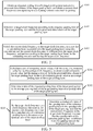
- FIG. 2 is a schematic flowchart of a computing resource adjustment method according to an embodiment of this application. As shown in FIG. 2 , the method may include:
- Step S101 Obtain an expected pooling time of a target pooling layer and a to-be-processed data volume of the target pooling layer, and obtain a current clock frequency corresponding to a computing resource unit used for pooling, a difference between the expected pooling time of the target pooling layer and an estimated convolution time of a convolution layer associated with the target pooling layer being less than a time threshold.
- a convolutional neural network model is formed by stacking a plurality of convolution layers and a plurality of pooling layers.
- a processing sequence is as follows: a convolution layer 1, a pooling layer 1, a convolution layer 2, a pooling layer 2, ..., a convolution layer N, and a pooling layer N.
- Convolution is performed in the convolution layers, and pooling is performed in the pooling layers.
- a convolution layer i and a pooling layer i are in the same layer, where i ⁇ [1, N ].
- pooling in the same layer is performed, that is, there is a sequence dependency relationship between convolution data generated by convolution and pooling data generated by pooling.
- the convolution data is generated first, and then the pooling data is generated.
- a pooling layer that is adjacent to a pooling layer under pooling and that has not been processed is referred to as a target pooling layer, or a pooling layer that is associated with a convolution layer under convolution is referred to as a target pooling layer.
- a target pooling layer there are four convolution layers and four pooling layers in the convolutional neural network model; if pooling is being performed in a pooling layer 2, a pooling layer 3 (a pooling layer adjacent to the pooling layer 2 and has not been processed) is a target pooling layer; if convolution is being performed in a convolution layer 2, the pooling layer 2 (a pooling layer associated with the convolution layer 2) is a target pooling layer.
- the expected pooling time of the target pooling layer and the to-be-processed data volume of the target pooling layer are obtained, where the expected pooling time of the target pooling layer is close to the estimated convolution time of the convolution layer associated with the target pooling layer (due to a hardware factor, the expected pooling time and the estimated convolution time in the same layer are close, but not equal). That is, the difference between the estimated convolution time of the convolution layer and the expected pooling time of the pooling layer in the same layer is within the time threshold.
- the time threshold is set in advance according to performance of the model and a current hardware parameter.
- the estimated convolution time of the convolution layer is related to the depth, complexity, and input data of a convolutional neural network model. Therefore, an estimated convolution time of any convolution layer in the convolutional neural network model may be predicted, and an expected pooling time of any pooling layer may be correspondingly predicted. For example, an estimated convolution time of a convolution layer 1 is 20 ⁇ s, an estimated convolution time of a convolution layer 2 is 30 ⁇ s, and a time threshold is 3 ms.
- an expected pooling time of a pooling layer 1 corresponding to the convolution layer 1 is 19 ⁇ s (a difference between the estimated convolution time and the expected pooling time is 1 ms and is less than the time threshold of 3 ms), and an expected pooling time of a pooling layer 2 corresponding to the convolution layer 2 is 32 ⁇ s (a difference between the estimated convolution time and the expected pooling time is 2 ms and is less than the time threshold of 3 ms).
- a clock frequency of a computing resource unit (the computing resource unit herein may be the computing unit 1 to the computing unit 5 in the embodiment of FIG. 1b ) used for pooling is referred to as a current clock frequency.
- a clock frequency of a computing resource unit may be referred to as a current clock frequency.
- the foregoing computing resource unit is used for pooling. Therefore, the clock frequency of the computing resource unit remains unchanged in the convolution process. For example, if pooling is being performed in the pooling layer 2, a clock frequency used for the pooling is 200 MHz. Therefore, a current clock frequency is 200 MHz.
- a current clock frequency is still 200 MHz, because during the convolution in the convolution layer 3, the current clock frequency of the computing resource unit is equal to the clock frequency in the adjacent pooling layer 2 that has been processed, that is, from the beginning of the pooling in the pooling layer 2 to the end of the convolution in the convolution layer 3, the current clock frequency of the computing resource unit used for pooling remains unchanged at 200 MHz.
- the computing resource unit is a minimum unit component used for a numeric operation, an instruction operation, and a logical operation in a central processing unit.
- the computing resource unit may operate at a plurality of clock frequencies. A higher clock frequency indicates stronger computing power, and a lower clock frequency indicates lower computing power.
- the computing resource unit used for pooling may be used for implementing boundary processing, slide window processing, a maximum pooling operation, or an average pooling operation in pooling.
- Step S102 Determine a target clock frequency according to the expected pooling time of the target pooling layer and the to-be-processed data volume of the target pooling layer.
- the average clock frequency is an average value of a plurality of clock frequencies provided by a system, and the computing power value refers to an instruction processing capacity value of the computing resource unit.
- a higher clock frequency indicates a higher power value of the computing resource unit, and the higher power value of the computing resource unit indicates higher power consumption;
- a lower clock frequency indicates a lower power value of the computing resource unit, and the lower power value of the computing resource unit indicates lower power consumption.
- the system may refer to a field programmable logic array (FPGA)-based hardware platform system, or may refer to an application-specific integrated circuit (ASIC) hardware platform system.
- FPGA field programmable logic array
- ASIC application-specific integrated circuit
- the reference pooling layer is a pooling layer that is adjacent to the target pooling layer and that is being processed or has been processed, that is, a pooling layer under pooling may be referred to as the reference pooling layer, or a pooling layer that is adjacent to a convolution layer under convolution and that has been processed may be referred to as the reference pooling layer.
- the speedup ratio of the reference pooling layer is determined according to an expected pooling time of the reference pooling layer and a to-be-processed data volume of the reference pooling layer.
- a specific process of determining the speedup ratio of the reference pooling layer includes: extracting the to-be-processed data volume of the reference pooling layer, determining a ratio of the to-be-processed data volume of the reference pooling layer to the total computing power value as an average pooling time of the reference pooling layer, and determining a ratio (a result obtained by dividing the expected pooling time of the reference pooling layer by the average pooling time of the reference pooling layer) of the expected pooling time of the reference pooling layer (a difference between the expected pooling time of the reference pooling layer and an estimated convolution time of a convolution layer associated with the reference pooling layer is within the time threshold) to the average pooling time of the reference pooling layer as the speedup ratio of the reference pooling layer.
- step S102 may further include: calculating a sum of computing power values of computing resource units having an average clock frequency, to obtain a total computing power value.
- the to-be-processed data volume of the target pooling layer is extracted, and a ratio of the to-be-processed data volume of the target pooling layer to the total computing power value is determined as an average pooling time of the target pooling layer.
- a ratio of the expected pooling time of the target pooling layer (the difference between the expected pooling time of the target pooling layer and the estimated convolution time of the convolution layer associated with the target pooling layer is within the time threshold) to the average pooling time is determined as a speedup ratio of the target pooling layer.
- the target clock frequency is determined according to the speedup ratio of the target pooling layer and the average clock frequency.
- the average clock frequency is the average value of the plurality of clock frequencies provided by the system. Based on the foregoing, the target clock frequency may be obtained based on the current clock frequency of the computing resource unit, or may be obtained based on the average clock frequency of the computing resource unit.
- the current clock frequency is a dynamic variable, and the average clock frequency is a fixed constant.
- Step S103 Switch the current clock frequency to the target clock frequency when a convolution layer associated with the target pooling layer completes convolution and the current clock frequency is different from the target clock frequency, and perform pooling in the target pooling layer based on the computing resource unit having the target clock frequency.
- the convolution layer associated with the target pooling layer completes convolution upon detecting that convolution data generated in the convolution layer associated with the target pooling layer reaches a data boundary.
- a boundary is added to an outer layer of the input image.
- a value 0 is added to the outer layer of the image, to expand the size of the input image, thereby ensuring the size of the feature image after convolution to be consistent with the size of the input image. Therefore, if it is continuously detected a value of convolution data generated after convolution is 0, it is determined that the convolution data reaches the data boundary.
- the current clock frequency and the target clock frequency are detected. If the current clock frequency is different from the target clock frequency, the current clock frequency is switched to the target clock frequency, and convolution data generated by convolution is extracted in the target pooling layer based on the computing resource unit having the target clock frequency, and pooling (boundary processing, slide window processing, a maximum pooling operation, or an average pooling operation) is performed on the convolution data. If the convolution layer associated with the target pooling layer completes convolution, and the current clock frequency is the same as the target clock frequency, the current clock frequency remains unchanged, and in the target pooling layer, based on the computing resource unit having the current clock frequency, pooling is continuously performed on the convolution data generated by the convolution.
- pooling boundary processing, slide window processing, a maximum pooling operation, or an average pooling operation
- the target clock frequency is calculated before pooling is performed in the target pooling layer.
- the target clock frequency may be calculated during pooling in the reference pooling layer, or may be calculated during convolution in the convolution layer associated with the target pooling layer.
- the target pooling layer is a next reference pooling layer, and a pooling layer that is adjacent to the target pooling layer and that has not been processed is a next target pooling layer.
- an actual pooling time of the target pooling layer is close to the expected pooling time of the target pooling layer and the estimated convolution time of the corresponding convolution layer, and the actual pooling time of the target pooling layer is actual duration counted after pooling in the target pooling layer is completed.
- FIG. 3 is a schematic flowchart of a method for determining a target clock frequency according to an embodiment of this application. As shown in FIG. 3 , a specific process of determining the target clock frequency includes the following step S201 to step S203, and step S201 to step S203 are a specific embodiment of step S102 in the embodiment corresponding to FIG. 2 .
- Step S201 Calculate a sum of computing power values of all the computing resource units having the average clock frequency, to obtain a total computing power value, and determine a ratio of the to-be-processed data volume of the target pooling layer to the total computing power value as an average pooling time of the target pooling layer.
- the sum of the computing power values of all the computing resource units having the average clock frequency is calculated to obtain the total computing power value.
- the average clock frequency refers to an average value of a plurality of clock frequencies provided by a system.
- a ratio (a result obtained by dividing the to-be-processed data volume of the target pooling layer by the total computing power value) of the to-be-processed data volume of the target pooling layer to the calculated total computing power value is determined as the target average pooling time.
- Step S202 Determine a ratio of the expected pooling time of the target pooling layer to the average pooling time of the target pooling layer as a speedup ratio of the target pooling layer.
- the ratio (a result obtained by dividing the expected pooling time of the target pooling layer by the average pooling time of the target pooling layer) of the expected pooling time of the target pooling layer to the average pooling time of the target pooling layer is determined as the speedup ratio of the target pooling layer.
- Step S203 Set the target clock frequency to a clock frequency the same as the current clock frequency when a speedup ratio of a reference pooling layer is the same as the speedup ratio of the target pooling layer.
- the speedup ratio of the reference pooling layer is extracted, and the speedup ratio of the target pooling layer and the speedup ratio of the reference pooling layer are detected.
- the target clock frequency is set to a clock frequency the same as the current clock frequency when the speedup ratio of the reference pooling layer is the same as the speedup ratio of the target pooling layer, that is, the current clock frequency remains unchanged when pooling is performed in the target pooling layer.
- the speedup ratio of the target pooling layer is 3
- the speedup ratio of the reference pooling layer is 3
- the current clock frequency is 350 MHz. Therefore, the target clock frequency is set to 350 MHz, that is, the target clock frequency is equal to the current clock frequency.
- the speedup ratio of the target pooling layer is 1 (indicating that the expected pooling time of the target pooling layer is close or equal to an actual pooling time of the target pooling layer), it only indicates that the target clock frequency is equal to the average clock frequency, but does not have any linear relationship with the current clock frequency. This is because the current clock frequency is a constantly adjusted variable and the current clock frequency may be equal or not equal to the average clock frequency. Therefore, if the current clock frequency is used to determine the target clock frequency, a relationship among the three variables, that is, the speedup ratio of the target pooling layer, the speedup ratio of the reference pooling layer, and the current clock frequency further needs to be considered.
- Step S204 Determine a ratio of the speedup ratio of the reference pooling layer to the speedup ratio of the target pooling layer as a speedup factor, and determine a product of the speedup factor and the current clock frequency as the target clock frequency when the speedup ratio of the reference pooling layer is different from the speedup ratio of the target pooling layer.
- the ratio (a result obtained by dividing the speedup ratio of the reference pooling layer by the speedup ratio of the target pooling layer) of the speedup ratio of the reference pooling layer to the speedup ratio of the target pooling layer is multiplied by the current clock frequency, to obtain the target clock frequency.
- the speedup ratio of the reference pooling layer is generated according to an expected pooling time of the reference pooling layer and a to-be-processed data volume of the reference pooling layer, and the reference pooling layer is a pooling layer that is adjacent to the target pooling layer and that is being processed or has been processed.
- a target clock frequency of a computing resource unit in next pooling is calculated according to a ratio between speedup ratios of two pooling layers and a current clock frequency.
- pooling is being performed in a reference pooling layer, and a current clock frequency of the reference pooling layer is 200MHz.
- An expected pooling time of a target pooling layer is 40 ⁇ s, and an average pooling time of the target pooling layer is 10 ⁇ s. Therefore, a speedup ratio of the target pooling layer is 4.
- An expected pooling time of the reference pooling layer is 60 ⁇ s, and an average pooling time of the reference pooling layer is 30 ⁇ s. Therefore, a speedup ratio of the reference pooling layer is 2.
- FIG. 4 is a schematic flowchart of another method for determining a target clock frequency according to an embodiment of this application.
- a specific process of determining the target clock frequency includes the following step S301 to step S303, and step S301 to step S303 are a specific embodiment of step S102 in the embodiment corresponding to FIG. 2 .
- Step S301 Calculate a sum of computing power values of all the computing resource units having the average clock frequency, to obtain a total computing power value, and determine a ratio of the to-be-processed data volume of the target pooling layer to the total computing power value as an average pooling time of the target pooling layer.
- the sum of the computing power values of all the computing resource units having the average clock frequency is calculated to obtain the total computing power value.
- the average clock frequency refers to an average value of a plurality of clock frequencies provided by a system.
- the ratio (a result obtained by dividing the to-be-processed data volume of the target pooling layer by the total computing power value) of the to-be-processed data volume of the target pooling layer to the calculated total computing power value is determined as the target average pooling time.
- Step S302. Determine a ratio of the expected pooling time of the target pooling layer to the average pooling time of the target pooling layer as a speedup ratio of the target pooling layer.
- the ratio (a result obtained by dividing the expected pooling time of the target pooling layer by the average pooling time of the target pooling layer) of the expected pooling time of the target pooling layer to the average pooling time of the target pooling layer is determined as the speedup ratio of the target pooling layer.
- Step S303 Determine a product of a reciprocal of the speedup ratio of the target pooling layer and the average clock frequency as the target clock frequency.
- an expected pooling time of a target pooling layer and a to-be-processed data volume of the target pooling layer are obtained, and a current clock frequency corresponding to a computing resource unit used for pooling is obtained; a target clock frequency is determined according to the expected pooling time of the target pooling layer and the to-be-processed data volume of the target pooling layer; the current clock frequency is switched to the target clock frequency when a convolution layer associated with the target pooling layer completes convolution and the current clock frequency is different from the target clock frequency; and pooling is performed in the target pooling layer based on the computing resource unit having the target clock frequency.
- a clock frequency of a computing resource unit may be dynamically adjusted according to an expected pooling time of a pooling layer and a to-be-processed data volume of the pooling layer, so that an actual pooling time of any pooling layer is close to an expected pooling time of the pooling layer, and the actual pooling time of any pooling layer matches an estimated convolution time of a corresponding convolution layer. Therefore, by adjusting the clock frequency of the computing resource unit, an actual pooling time and an estimated convolution time of any layer may be close to each other as required, thus avoiding idling of computing resources, and improving utilization of the computing resources.
- FIG. 5 is a schematic flowchart of another computing resource adjustment method according to an embodiment of this application.
- the computing resource adjustment method may include: Step S401. Predict estimated convolution times of a plurality of convolution layers, determine expected pooling times of a plurality of pooling layers according to the estimated convolution times of the plurality of convolution layers, and determine an expected pooling value according to the expected pooling times of the plurality of pooling layers.
- an estimated convolution time of each convolution layer in the convolutional neural network model is predicted, expected pooling times of a plurality of pooling layers are determined according to the predicted estimated convolution times of the plurality of convolution layers. Due to a hardware factor, a difference between the estimated convolution time of the convolution layer and the expected pooling time of the pooling layer in the same layer is within a time threshold.
- the expected pooling value is determined according to the expected pooling times of the plurality of pooling layers in the convolutional neural network model.
- the expected pooling value is obtained by calculating an average value of the expected pooling times of the plurality of pooling layers, and represents an average value of the expected pooling times.
- an estimated convolution time of a convolution layer 1 is 20 ⁇ s
- an estimated convolution time of a convolution layer 2 is 50 ⁇ s
- an estimated convolution time of a convolution layer 3 is 10 ⁇ s.
- An expected pooling time of a pooling layer 1 corresponding to the convolution layer 1 is 18 ⁇ s
- an expected pooling time of a pooling layer 2 corresponding to the convolution layer 2 is 53 ⁇ s
- an expected pooling time of a pooling layer 3 corresponding to the convolution layer 3 is 12 ⁇ s.
- Step S402. Predict to-be-processed data volumes of the plurality of pooling layers, and determine a basic pooling data volume according to the to-be-processed data volumes of the plurality of pooling layers.
- a to-be-processed data volume of each pooling layer in the convolutional neural network model is predicted.
- a minimum to-be-processed data volume is extracted from the to-be-processed data volumes of the plurality of pooling layers to serve as a basic pooling data volume.
- a minimum to-be-processed data volume is selected as the basic pooling data volume to reduce an area of a computing chip occupied during pooling, and maximize computing efficiency of the computing resource unit.
- a to-be-processed data volume of a pooling layer 1 is 2KB
- a to--be-processed data volume of a pooling layer 2 is 3 KB
- a to-be-processed data volume of a pooling layer 3 is 5 KB. Therefore, 2 KB is a basic pooling data volume (2 KB ⁇ 3 KB ⁇ 5 KB).
- Step S403. Determine a quantity of computing resource units used for pooling according to the expected pooling value, the basic pooling data volume, and a computing power value of the computing resource unit having an average clock frequency, the average clock frequency being an average value of a plurality of clock frequencies provided by a system.
- a product of the expected pooling value and the computing power value of the computing resource unit having the average clock frequency is divided by the basic pooling data volume, that is, (the expected pooling value*the computing power value of the computing resource unit having the average clock frequency)/the basic pooling data volume, to obtain the quantity of computing resource units used for pooling.
- the quantity of computing resource units is no longer adjusted in subsequent convolution and pooling, and only a frequency of the computing resource unit is adjusted.
- the average clock frequency is the average value of the plurality of clock frequencies provided by the system
- the computing power value refers to an instruction processing capacity value of the computing resource unit, and a higher computing power value indicates a stronger instruction processing capacity of the computing resource unit.
- FIG. 6 is a schematic flowchart of determining a quantity of computing resource units according to an embodiment of this application.
- estimated convolution times TC1-TCn corresponding to n convolution layers in the convolutional neural network model are predicted, where TCn represents an estimated convolution time of an n th convolution layer.
- Expected pooling times TP1-TPn of pooling layers corresponding to the convolution layers are predicted according to the plurality of estimated convolution times, where TPn represents an expected pooling time of an n th pooling layer.
- To-be-processed data volumes VP1-VPn of the n pooling layers are predicted, where VPn represents a to-be-processed data volume of an n th pooling layer.
- a minimum to-be-processed data volume is extracted from the foregoing plurality of to-be-processed data volumes to serve as a basic pooling data volume Min_VP.
- Step S404 Obtain an expected pooling time of a target pooling layer and a to-be-processed data volume of the target pooling layer, and obtain a current clock frequency corresponding to the computing resource unit used for pooling, a difference between the expected pooling time of the target pooling layer and an estimated convolution time of a convolution layer associated with the target pooling layer being less than a time threshold.
- Step S405. Determine a target clock frequency according to the expected pooling time of the target pooling layer and the to-be-processed data volume of the target pooling layer.
- step S404 and step S405 For the specific implementation of step S404 and step S405, reference may be made to the descriptions about step S101 and step S102 in the embodiment corresponding to FIG. 2 , and for the specific process of determining a target clock frequency, reference may be made to step S201 to step S203 in FIG. 3 and step S301 to step S303 in FIG. 4 . Details are not described herein again.
- Step S406 Delete clock frequencies other than the target clock frequency in a plurality of clock frequencies provided by a system.
- the system provides a plurality of clock frequencies for the computing resource unit. To reduce power consumption, all (unused) clock frequencies other than the target clock frequency are deleted after the target clock frequency is determined.
- Step S407. Switch the current clock frequency to the target clock frequency when a convolution layer associated with the target pooling layer completes convolution and the current clock frequency is different from the target clock frequency, and perform pooling in the target pooling layer based on the computing resource unit having the target clock frequency.
- step S407 For the specific implementation of step S407, reference may be made to the description about step S103 in the embodiment corresponding to FIG. 2 , and details are not described herein again.
- FIG. 7 is a schematic diagram of interaction for switching a target clock frequency according to an embodiment of this application.
- a clock frequency generator 200a in a system generates clocks with different frequencies, to drive different computing power values of a computing resource unit.
- a convolution data memory 200d stores convolution data generated after convolution.
- a clock frequency selector 200b calculates a speedup ratio of a target pooling layer, and determines a target clock frequency.
- the clock frequency selector 200b selects the target clock frequency for a computing resource unit 1, a computing resource unit 2, ..., a computing resource unit n from a plurality of clock frequencies generated by the clock frequency generator 200a (the clock frequency selector 200b has determined the target clock frequency in a previous convolution process or pooling process), and deletes (that is, shields) the remaining clock frequencies, to reduce power consumption of the system.
- the clock frequency of the computing resource unit is switched to the target clock frequency, and pooling is performed on the convolution data by using the computing resource unit 1 having the target clock frequency, the computing resource unit 2 having the target clock frequency, ..., the computing resource unit n having the target clock frequency.
- the data boundary detector 200c keeps performing detection in the convolution process.
- the clock frequency generator 200a, the clock frequency selector 200b, and the data boundary detector 200c may be integrated into the clock frequency controller 100g shown in FIG. 1b .
- a convolutional neural network model is deployed in an FPGA cloud server configured to perform cloud computing, that is, a computing resource pool for convolution computation, a convolution data storage unit, a computing resource pool for pooling computation, a pooling data storage unit, and a clock frequency controller (which may be the clock frequency controller 100g shown in FIG. 1b ) are deployed on FPGA hardware in the FPGA cloud server, where the computing resource pool for pooling computation may include the computing resource unit 1, the computing resource unit 2, ..., the computing resource unit n in the embodiment corresponding to FIG. 7 .
- the clock frequency controller calculates a speedup ratio of a target pooling layer according to an expected pooling time of the target pooling layer and an average pooling time of the target pooling layer, and determines a target clock frequency.
- convolution data obtained by convolution is stored in the convolution data storage unit, and the clock frequency controller selects, from a plurality of clock frequencies provided by the FPGA, a predetermined target clock frequency for the computing resource pool for pooling computation, and shields the remaining clock frequencies, to reduce power consumption of the system.
- the clock frequency controller switches a current clock frequency to the target clock frequency, and the convolution data stored in the convolution data storage unit is pooled by using the computing resource pool that is used for pooling computation and that has the target clock frequency, and pooling data after pooling is stored in the pooling data storage unit.
- the FPGA may provide a powerful computing capacity, so that after the convolutional neural network model is built in the FPGA cloud server, the convolutional neural network model may be run smoothly.
- an expected pooling time of a target pooling layer and a to-be-processed data volume of the target pooling layer are obtained, and a current clock frequency corresponding to the computing resource unit used for pooling is obtained; a target clock frequency is determined according to the expected pooling time of the target pooling layer and the to-be-processed data volume of the target pooling layer; a current clock frequency is switched to the target clock frequency when a convolution layer associated with the target pooling layer completes convolution and the current clock frequency is different from the target clock frequency; and pooling is performed in the target pooling layer based on the computing resource unit having the target clock frequency.
- a clock frequency of a computing resource unit may be dynamically adjusted according to an expected pooling time of a pooling layer and a to-be-processed data volume of the pooling layer, so that an actual pooling time of any pooling layer is close to an expected pooling time of the pooling layer, and the actual pooling time of any pooling layer matches an estimated convolution time of a corresponding convolution layer. Therefore, by adjusting the clock frequency of the computing resource unit, an actual pooling time and an estimated convolution time of any layer may be close to each other as required, thus avoiding idling of computing resources, and improving utilization of the computing resources.
- FIG. 8 is a schematic structural diagram of a computing resource adjustment apparatus according to an embodiment of this application.
- the computing resource adjustment apparatus 1 may include: an obtaining module 11, a first determining module 12, and a switching module 13.
- the obtaining module 11 is configured to obtain an expected pooling time of a target pooling layer and a to-be-processed data volume of the target pooling layer, and obtain a current clock frequency corresponding to a computing resource unit used for pooling, a difference between the expected pooling time of the target pooling layer and an estimated convolution time of a convolution layer associated with the target pooling layer being less than a time threshold.
- the first determining module 12 is configured to determine a target clock frequency according to the expected pooling time of the target pooling layer and the to-be-processed data volume of the target pooling layer.
- the switching module 13 is configured to switch the current clock frequency to the target clock frequency when the convolution layer associated with the target pooling layer completes convolution and the current clock frequency is different from the target clock frequency, and perform pooling in the target pooling layer based on the computing resource unit having the target clock frequency.
- step S101 to step S103 for a specific implementation of functions of the obtaining module 11, the first determining module 12, and the switching module 13, reference may be made to step S101 to step S103 in the embodiment corresponding to FIG. 2 , and details are not described herein again.
- the computing resource adjustment apparatus 1 may include: the obtaining module 11, the first determining module 12, and the switching module 13, and the computing resource adjustment apparatus 1 may further include: a first prediction module 14, a second prediction module 15, a second determining module 16, and a third determining module 17.
- the first prediction module 14 is configured to predict estimated convolution times of a plurality of convolution layers, determine expected pooling times of a plurality of pooling layers according to the estimated convolution times of the plurality of convolution layers, and determine an expected pooling value according to the expected pooling times of the plurality of pooling layers.
- the second prediction module 15 is configured to predict to-be-processed data volumes of the plurality of pooling layers, and determine a basic pooling data volume according to the to-be-processed data volumes of the plurality of pooling layers.
- the second prediction module 15 is specifically configured to extract a minimum to-be-processed data volume from the to-be-processed data volumes of the plurality of pooling layers as the basic pooling data volume.
- the second determining module 16 is configured to determine a quantity of computing resource units used for pooling according to the expected pooling value, the basic pooling data volume, and a computing power value of the computing resource unit having an average clock frequency, the average clock frequency being an average value of a plurality of clock frequencies provided by a system.
- the third determining module 17 is configured to determine that the convolution layer associated with the target pooling layer completes convolution upon detecting that convolution data generated in the convolution layer associated with the target pooling layer reaches a data boundary.
- step S401 For a specific implementation of functions of the first prediction module 14, the second prediction module 15, and the second determining module 16, reference may be made to step S401 to step S403 in the embodiment corresponding to FIG. 5 , and for a specific implementation of functions of the third determining module 17, reference may be made to step S103 in the embodiment corresponding to FIG. 2 , and details are not described herein again.
- the first prediction module 14 may include: a first determining unit 141 and a second determining unit 142.
- the first determining unit 141 is configured to determine the expected pooling times of the plurality of pooling layers according to the estimated convolution times of the plurality of convolution layers, a difference between an estimated convolution time of a convolution layer and an expected pooling time of a pooling layer in the same layer being less than the time threshold.
- the second determining unit 142 is configured to calculate an average value of the expected pooling times of the plurality of pooling layers, and determine the average value as the expected pooling value.
- step S401 For a specific implementation of functions of the first determining unit 141 and the second determining unit 142, reference may be made to step S401 in the embodiment corresponding to FIG. 5 , and details are not described herein again.
- the first determining module 12 may include: a third determining unit 121, a fourth determining unit 122, and a fifth determining unit 123.
- the third determining unit 121 is configured to calculate a sum of computing power values of all the computing resource units having the average clock frequency, to obtain a total computing power value, and determine a ratio of the to-be-processed data volume of the target pooling layer to the total computing power value as an average pooling time of the target pooling layer.
- the fourth determining unit 122 is configured to determine a ratio of the expected pooling time of the target pooling layer to the average pooling time of the target pooling layer as a speedup ratio of the target pooling layer.
- the fifth determining unit 123 is configured to determine the target clock frequency according to the speedup ratio of the target pooling layer, a speedup ratio of a reference pooling layer, and the current clock frequency, the speedup ratio of the reference pooling layer being generated according to an expected pooling time of the reference pooling layer and a to-be-processed data volume of the reference pooling layer, and the reference pooling layer being a pooling layer that is adjacent to the target pooling layer and that is being processed or has been processed.
- step S201 For a specific implementation of functions of the third determining unit 121, the fourth determining unit 122, and the fifth determining unit 123, reference may be made to step S201 to step S203 in the embodiment corresponding to FIG. 3 , and details are not described herein again.
- the fifth determining unit 123 may include a first determining subunit 1231, a second determining subunit 1232, and a deletion subunit 1233.
- the first determining subunit 1231 is configured to set the target clock frequency to a clock frequency the same as the current clock frequency when the speedup ratio of the reference pooling layer is the same as the speedup ratio of the target pooling layer.
- the second determining subunit 1232 is configured to determine a ratio of the speedup ratio of the reference pooling layer to the speedup ratio of the target pooling layer as a speedup factor when the speedup ratio of the reference pooling layer is different from the speedup ratio of the target pooling layer, and determine a product of the speedup factor and the current clock frequency as the target clock frequency.
- step S203 For a specific implementation of functions of the first determining subunit 1231, the second determining subunit 1232, and the deletion subunit 1233, reference may be made to step S203 in the embodiment corresponding to FIG. 3 , and details are not described herein again.
- the fifth determining module 123 may include the first determining subunit 1231, the second determining subunit 1232, and the deletion subunit 1233, and may further include the deletion subunit 1233.
- the deletion subunit 1233 is configured to delete clock frequencies other than the target clock frequency in a plurality of clock frequencies provided by a system.
- step S406 for a specific implementation of a function of the deletion subunit 1233, reference may be made to step S406 in the embodiment corresponding to FIG. 5 , and details are not described herein again.
- the first determining module 12 may further include: a sixth determining unit 124, a seventh determining unit 125, and an eighth determining unit 126.
- the sixth determining unit 124 is configured to calculate a sum of computing power values of all the computing resource units having the average clock frequency, to obtain a total computing power value, and determine a ratio of the to-be-processed data volume of the target pooling layer to the total computing power value as an average pooling time of the target pooling layer.
- the seventh determining unit 125 is configured to determine a ratio of the expected pooling time of the target pooling layer to the average pooling time of the target pooling layer as a speedup ratio of the target pooling layer.
- the eighth determining unit 126 is configured to determine the target clock frequency according to the speedup ratio of the target pooling layer and the average clock frequency.
- the eighth determining unit 126 is specifically configured to determine a product of a reciprocal of the speedup ratio of the target pooling layer and the average clock frequency as the target clock frequency.
- step S301 For a specific implementation of functions of the sixth determining unit 124, the seventh determining unit 125, and the eighth determining unit 126, reference may be made to step S301 to step S303 in the embodiment corresponding to FIG. 4 , and details are not described herein again.
- an expected pooling time of a target pooling layer and a to-be-processed data volume of the target pooling layer are obtained, and a current clock frequency corresponding to a computing resource unit used for pooling is obtained; a target clock frequency is determined according to the expected pooling time of the target pooling layer and the to-be-processed data volume of the target pooling layer; the current clock frequency is switched to the target clock frequency when a convolution layer associated with the target pooling layer completes convolution and the current clock frequency is different from the target clock frequency; and pooling is performed in the target pooling layer based on the computing resource unit having the target clock frequency.
- a clock frequency of a computing resource unit may be dynamically adjusted according to an expected pooling time of a pooling layer and a to-be-processed data volume of the pooling layer, so that an actual pooling time of any pooling layer is close to an expected pooling time of the pooling layer, and the actual pooling time of any pooling layer matches an estimated convolution time of a corresponding convolution layer. Therefore, by adjusting the clock frequency of the computing resource unit, an actual pooling time and an estimated convolution time of any layer may be close to each other as required, thus avoiding idling of computing resources, and improving utilization of the computing resources.
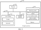
- FIG. 9 is a schematic structural diagram of a computing device according to an embodiment of this application.
- the computing device may be a terminal device or a server.
- the computing resource adjustment apparatus in FIG. 8 may be applied to the computing device 1000.
- the computing device 1000 may include: a processor 1001, a network interface 1004, and a memory 1005.
- the computing device 1000 may further include: a user interface 1003 and at least one communications bus 1002.
- the communications bus 1002 is configured to implement connection and communication between these components.
- the user interface 1003 may include a display and a keyboard.
- the user interface 1003 may further include a standard wired interface and a wireless interface.
- the network interface 1004 may include a standard wired interface and a wireless interface (such as a WiFi interface).
- the memory 1005 may be a high-speed RAM, or may be a non-volatile memory, for example, at least one magnetic disk memory. In some embodiments, the memory 1005 may further be at least one storage apparatus that is located away from the processor 1001. As shown in FIG. 9 , the memory 1005 used as a computer storage medium may include an operating system, a network communications module, a user interface module, and a device-control application program.
- the network interface 1004 is mainly configured to provide a network communication function.
- the user interface 1003 is mainly configured to provide an input interface for a user.
- the processor 1001 may be configured to invoke the device-control application program stored in the memory 1005, to implement the following operations:
- the processor 1001 further performs the following step:
- the processor 1001 when performing the step of determining expected pooling times of a plurality of pooling layers according to the estimated convolution times of the plurality of convolution layers, and determining an expected pooling value according to the expected pooling times of the plurality of pooling layers, the processor 1001 specifically performs the following steps:
- the processor 1001 when performing the step of determining a basic pooling data volume according to the to-be-processed data volumes of the plurality of pooling layers, specifically performs the following step: extracting a minimum to-be-processed data volume from the to-be-processed data volumes of the plurality of pooling layers as the basic pooling data volume.
- the processor 1001 when performing the step of determining a target clock frequency according to the expected pooling time of the target pooling layer and the to-be-processed data volume of the target pooling layer, the processor 1001 specifically performs the following steps:
- the processor 1001 when performing the step of determining a target clock frequency according to the speedup ratio of the target pooling layer, a speedup ratio of a reference pooling layer, and the current clock frequency, the processor 1001 specifically performs the following steps:
- the processor 1001 further performs the following step: deleting clock frequencies other than the target clock frequency in the plurality of clock frequencies provided by the system.
- the processor 1001 when performing the step of determining a target clock frequency according to the expected pooling time of the target pooling layer and the to-be-processed data volume of the target pooling layer, the processor 1001 specifically performs the following steps:
- the processor 1001 when performing the step of determining a target clock frequency according to the speedup ratio of the target pooling layer and the average clock frequency, specifically performs the following step: determining a product of a reciprocal of the speedup ratio of the target pooling layer and the average clock frequency as the target clock frequency.
- the processor 1001 further performs the following step: determining that the convolution layer associated with the target pooling layer completes convolution upon detecting that convolution data generated in the convolution layer associated with the target pooling layer reaches a data boundary.
- an expected pooling time of a target pooling layer and a to-be-processed data volume of the target pooling layer are obtained, and a current clock frequency corresponding to the computing resource unit used for pooling is obtained; a target clock frequency is determined according to the expected pooling time of the target pooling layer and the to-be-processed data volume of the target pooling layer; the current clock frequency is switched to the target clock frequency when a convolution layer associated with the target pooling layer completes convolution and the current clock frequency is different from the target clock frequency; and pooling is performed in the target pooling layer based on the computing resource unit having the target clock frequency.
- a clock frequency of a computing resource unit may be dynamically adjusted according to an expected pooling time of a pooling layer and a to-be-processed data volume of the pooling layer, so that an actual pooling time of any pooling layer is close to an expected pooling time of the pooling layer, and the actual pooling time of any pooling layer matches an estimated convolution time of a corresponding convolution layer. Therefore, by adjusting the clock frequency of the computing resource unit, an actual pooling time and an estimated convolution time of any layer are close to each other as required, thus avoiding idling of computing resources, and improving utilization of the computing resources.
- terminal device 1000 described in the embodiment of this application may perform descriptions about the computing resource adjustment method in the embodiments corresponding to FIG. 2 to FIG. 7 , or may execute descriptions about the computing resource adjustment apparatus in the embodiment corresponding to FIG. 8 , and details are not described herein again. In addition, beneficial effects achieved by using the same method are not described herein again.
- an embodiment of this application further provides a computer storage medium.
- the computer storage medium stores a computer program executed by the computing resource adjustment apparatus 1 mentioned above, and the computer program includes a program instruction.
- the processor can perform the descriptions about the computing resource adjustment method in the embodiments corresponding to FIG. 2 to FIG. 7 . Therefore, details are not described herein again.
- beneficial effects achieved by using the same method are not described herein again.
- technical details that are not disclosed in the embodiment of the computer storage medium in this application refer to descriptions of the method embodiments of this application.
- a person of ordinary skill in the art may understand that all or some of the processes of the methods in the embodiments may be implemented by a computer program instructing relevant hardware.
- the program may be stored in a computer-readable storage medium. When the program runs, the processes of the methods in the embodiments may be performed.
- the foregoing storage medium may be a magnetic disk, an optical disc, a read-only memory (ROM), a random access memory (RAM), or the like.
Landscapes
- Engineering & Computer Science (AREA)
- Theoretical Computer Science (AREA)
- Physics & Mathematics (AREA)
- General Physics & Mathematics (AREA)
- General Engineering & Computer Science (AREA)
- Software Systems (AREA)
- Health & Medical Sciences (AREA)
- Life Sciences & Earth Sciences (AREA)
- Biomedical Technology (AREA)
- Biophysics (AREA)
- Computing Systems (AREA)
- Artificial Intelligence (AREA)
- Molecular Biology (AREA)
- Evolutionary Computation (AREA)
- Data Mining & Analysis (AREA)
- Mathematical Physics (AREA)
- Computational Linguistics (AREA)
- General Health & Medical Sciences (AREA)
- Mathematical Optimization (AREA)
- Computational Mathematics (AREA)
- Mathematical Analysis (AREA)
- Pure & Applied Mathematics (AREA)
- Neurology (AREA)
- Power Sources (AREA)
- Management, Administration, Business Operations System, And Electronic Commerce (AREA)
- Synchronisation In Digital Transmission Systems (AREA)
Abstract
Description
- This application claims priority to Chinese Patent Application No.
201810072678.9 - This application relates to the field of computer technologies, and in particular, to a computing resource adjustment method and apparatus, a neural network operational method and apparatus, and a related device.
- A convolutional neural network (CNN) is a kind of artificial neural network, and has become a research hotspot in the fields of speech analysis, image recognition, object classification, and the like. A weight sharing network structure of the convolutional neural network makes it more similar to a biological neural network, thereby reducing the complexity of a network model, and reducing the quantity of weights. The convolutional neural network is formed by stacking convolution layers and pooling layers in various forms, and the depth of a model expands from a dozen layers to hundreds of layer.
- As the depth of the model increases, the requirements for computing power also gradually increase. To improve parallel efficiency of algorithms in the same layer, a convolution computation time and a pooling computation time in the same layer are required to be equal or close to each other. However, convolution computation and pooling computation are inhomogeneous in the algorithms, that is, the amount of convolution computation and the amount of pooling computation in the same layer may be in a directly proportional relationship or an inversely proportional relationship. For example, the amount of convolution computation in the second layer is twice the amount of convolution computation in the first layer. However, the amount of pooling computation in the second layer may be 10 times or 0. 1 times the amount of pooling computation in the first layer. Therefore, if the pooling computation time and the convolution computation time in the same layer are desired to match each other, the worst scenario requirements need to be satisfied first, which causes the consumption of a large quantity of computing resources. However, there are idle computing resources in actual running, and as a result, utilization of the computing resources is low.
- An embodiment of this application provides a computing resource adjustment method, performed by a computing device, including:
- obtaining an expected pooling time of a target pooling layer and a to-be-processed data volume of the target pooling layer, and obtaining a current clock frequency corresponding to a computing resource unit used for pooling, a difference between the expected pooling time of the target pooling layer and an estimated convolution time of a convolution layer associated with the target pooling layer being less than a time threshold;
- determining a target clock frequency according to the expected pooling time of the target pooling layer and the to-be-processed data volume of the target pooling layer; and
- switching the current clock frequency to the target clock frequency when the convolution layer associated with the target pooling layer completes convolution and the current clock frequency is different from the target clock frequency, and performing pooling in the target pooling layer based on the computing resource unit having the target clock frequency.
- An embodiment of this application further provides a neural network operational method, performed by a computing device, including:
- obtaining an expected pooling time of a target pooling layer and a to-be-processed data volume of the target pooling layer, and obtaining a current clock frequency corresponding to a computing resource unit used for pooling, a difference between the expected pooling time of the target pooling layer and an estimated convolution time of a convolution layer associated with the target pooling layer being less than a time threshold;
- determining a target clock frequency according to the expected pooling time of the target pooling layer and the to-be-processed data volume of the target pooling layer; and
- switching the current clock frequency to the target clock frequency when the convolution layer associated with the target pooling layer completes convolution and the current clock frequency is different from the target clock frequency, and performing pooling in the target pooling layer based on the computing resource unit having the target clock frequency.
- An embodiment of this application further provides a computing resource adjustment apparatus, including:
- an obtaining module, configured to obtain an expected pooling time of a target pooling layer and a to-be-processed data volume of the target pooling layer, and obtain a current clock frequency corresponding to a computing resource unit used for pooling, a difference between the expected pooling time of the target pooling layer and an estimated convolution time of a convolution layer associated with the target pooling layer being less than a time threshold;
- a first determining module, configured to determine a target clock frequency according to the expected pooling time of the target pooling layer and the to-be-processed data volume of the target pooling layer; and
- a switching module, configured to switch the current clock frequency to the target clock frequency when the convolution layer associated with the target pooling layer completes convolution and the current clock frequency is different from the target clock frequency, and perform pooling in the target pooling layer based on the computing resource unit having the target clock frequency.
- An embodiment of this application further provides a neural network operational apparatus, including:
- an obtaining module, configured to obtain an expected pooling time of a target pooling layer and a to-be-processed data volume of the target pooling layer, and obtain a current clock frequency corresponding to a computing resource unit used for pooling, a difference between the expected pooling time of the target pooling layer and an estimated convolution time of a convolution layer associated with the target pooling layer being less than a time threshold;
- a first determining module, configured to determine a target clock frequency according to the expected pooling time of the target pooling layer and the to-be-processed data volume of the target pooling layer; and
- a switching module, configured to switch the current clock frequency to the target clock frequency when the convolution layer associated with the target pooling layer completes convolution and the current clock frequency is different from the target clock frequency, and perform pooling in the target pooling layer based on the computing resource unit having the target clock frequency.
- An embodiment of this application further provides a computing device, including a processor and a memory,
the processor being connected to the memory, the memory being configured to store a program code, and the processor being configured to invoke the program code to perform the foregoing method. - An embodiment of this application further provides a computer storage medium, the computer storage medium storing a computer program, the computer program including a program instruction, and the program instruction, when executed by a processor, performing the foregoing method.
- To describe the technical solutions in the embodiments of this application or in the existing technology more clearly, the following briefly describes the accompanying drawings required for describing the embodiments or the existing technology. Apparently, the accompanying drawings in the following description show merely some embodiments of this application, and a person of ordinary skill in the art may still derive other drawings from these accompanying drawings without creative efforts.
-
FIG. 1a and FIG. 1b are schematic diagrams of a scenario of a computing resource adjustment method according to an embodiment of this application. -
FIG. 2 is a schematic flowchart of a computing resource adjustment method according to an embodiment of this application. -
FIG. 3 is a schematic flowchart of a method for determining a target clock frequency according to an embodiment of this application. -
FIG. 4 is a schematic flowchart of another method for determining a target clock frequency according to an embodiment of this application. -
FIG. 5 is a schematic flowchart of another computing resource adjustment method according to an embodiment of this application. -
FIG. 6 is a schematic flowchart of determining a quantity of computing resource units according to an embodiment of this application. -
FIG. 7 is a schematic diagram of interaction for switching a target clock frequency according to an embodiment of this application. -
FIG. 8 is a schematic structural diagram of a computing resource adjustment apparatus according to an embodiment of this application. -
FIG. 9 is a schematic structural diagram of a terminal device according to an embodiment of this application. - The following clearly and completely describes the technical solutions in the embodiments of this application with reference to the accompanying drawings in the embodiments of this application. Apparently, the described embodiments are only some embodiments of this application rather than all of the embodiments. All other embodiments obtained by a person of ordinary skill in the art based on the embodiments of this application without creative efforts shall fall within the protection scope of this application.
- An embodiment of this application provides a computing resource adjustment method. The method may be applied to a terminal device or a server, and is particularly applicable to a scenario with massive data computation requirements, for example, a scenario in which massive yellow images are detected or massive images need to be classified. The method is also particularly applied to a scenario in which the terminal device is sensitive to power consumption, for example, image detection and recognition of an intelligent terminal device and an unmanned aerial vehicle.
- In the following embodiments of this application, the foregoing method being applied to the terminal device is used as an example for description.
-
FIG. 1a and FIG. 1b are schematic diagrams of a scenario of a computing resource adjustment method according to an embodiment of this application. - As shown in
FIG. 1a , two convolution layers (a first convolution layer and a second convolution layer) and two pooling layers (a first pooling layer and a second pooling layer) in a convolutional neural network model are used as an example for description. A size of an image inputted to the convolutional neural network model is 256 × 256. Therefore, it may be predicted that an estimated convolution time of the first convolution layer is 30 µs, an estimated convolution time of the second convolution layer is 50 µs, a data volume of the first pooling layer is 4 KB, and a data volume of the second pooling layer is 1 KB. To make a convolution operation time and a pooling operation time in the same layer match each other, an estimated convolution time of a convolution layer and an expected pooling time of a corresponding pooling layer in the same layer are close. Herein, due to a hardware factor, the expected pooling time and the estimated convolution time are close but not equal, that is, it is predicted that an expected pooling time of the first pooling layer may be 33 µs and an expected pooling time of the second pooling layer may be 46 µs. - In a general condition, an average clock frequency of a single computing unit is 300 MHz, and a corresponding computing power value is 1. The general condition means that temperature of a central processing unit is 40°C or lower. As shown in
FIG. 1b , according to the foregoing conditions, that is, the expected pooling time of the first pooling layer is 33 µs, the expected pooling time of the second pooling layer is 46 µs, a minimum data volume of the two pooling layers is 1 KB, and the computing power value of the single computing unit is 1, it may be calculated in advance that the quantity of computing units used for pooling operations is 5. Once the quantity of computing units is determined, it will not be changed in subsequent convolution operations and pooling operations, only a clock frequency of the computing unit is adjusted. After the quantity of computing units is determined, animage 100a with a size of 256 × 256 is inputted to an input layer of a convolutional neural network. A convolution kernel, as a window, slides through all areas of theimage 100a in sequence, that is, the convolution kernel performs a convolution operation in theimage 100a. During 30µs of a convolution operation process in the first convolution layer, that is, during the predicted 30 µs estimated convolution time of the first convolution layer, according to the 33 µs expected pooling time of the first pooling layer, the corresponding data volume 4 KB, and a 300 MHz current clock frequency of the computing unit, aclock frequency controller 100g may calculate in advance that a target clock frequency is 450 MHz. - After the convolution operation is performed on the
image 100a in the first convolution layer, afeature image 100b is generated. Thefeature image 100b is stored in a convolutiondata storage unit 100f, and theclock frequency controller 100g adjusts the clock frequency of acomputing unit 1 from 300 MHz to 450 MHz, the clock frequency of acomputing unit 2 from 300 MHz to 450 MHz, the clock frequency of a computing unit 3 from 300 MHz to 450 MHz, the clock frequency of a computing unit 4 from 300 MHz to 450 MHz, and the clock frequency of acomputing unit 5 from 300 MHz to 450 MHz. After all the computing units are adjusted, thefeature image 100b stored in the convolutiondata storage unit 100f is inputted to the first pooling layer, and a pooling operation is performed on thefeature image 100b by using the five computing units having the clock frequency of 450 MHz. An actual pooling time of the pooling operation is 28 µs, that is, the actual pooling time (28 µs) of the first pooling layer is close to the estimated convolution time (30 µs) of the first convolution layer. Afeature image 100c obtained after pooling is stored in a poolingdata storage unit 100h and used for a convolution operation of the second convolution layer. - The
feature image 100c is inputted to the second convolution layer for a convolution operation. During 50 µs of a convolution operation process in the second convolution layer, that is, during the predicted 50 µs estimated convolution time of the second convolution laver according to the 46 µs expected pooling time of the second pooling layer, the correspondingdata volume 1 KB, and a 450 MHz current clock frequency corresponding to each computing unit, theclock frequency controller 100g may calculate that the target clock frequency is 100 MHz. Herein, the current clock frequency in this round is 450 MHz because in the previous pooling operation process, the clock frequency is adjusted from 300 MHz to 450 MHz, while the current clock frequency of the second convolution layer is the same as the current clock frequency of the first pooling layer. - After the convolution operation is performed on the
feature image 100c in the second convolution layer, afeature image 100d is generated. Thefeature image 100d is stored in the convolutiondata storage unit 100f, and theclock frequency controller 100g adjusts the clock frequency of thecomputing unit 1 from 450 MHz to 100 MHz, the clock frequency of thecomputing unit 2 from 450 MHz to 100 MHz, the clock frequency of the computing unit 3 from 450 MHz to 100 MHz, the clock frequency of the computing unit 4 from 450 MHz to 100 MHz, and the clock frequency of thecomputing unit 5 from 450 MHz to 100 MHz. After all the computing units are adjusted, thefeature image 100d stored in the convolutiondata storage unit 100f is inputted to the second pooling layer, and a pooling operation is performed on thefeature image 100d by using the five computing units having the clock frequency of 100 MHz. An actual pooling time of the pooling operation is 52 µs, that is, the actual pooling time (52 µs) of the second pooling layer is close to the estimated convolution time (50 µs) of the second convolution layer. Afeature image 100e obtained after pooling is stored in the poolingdata storage unit 100h. - In the foregoing technical solution, by adjusting the clock frequencies of the computing units, the actual pooling time and the estimated convolution time in the same layer are close, so that the convolution time and the pooling time may become homogeneous, computing resources are saved, and the computing resources are prevented from staying in an idle state, thus improving utilization of the computing resources. For specific processes of determining the quantity of computing units, determining the target clock frequency, and adjusting the clock frequency of a computing resource unit, reference may be made to embodiments corresponding to
FIG. 2 to FIG. 7 below. - Further,
FIG. 2 is a schematic flowchart of a computing resource adjustment method according to an embodiment of this application. As shown inFIG. 2 , the method may include: - Step S101. Obtain an expected pooling time of a target pooling layer and a to-be-processed data volume of the target pooling layer, and obtain a current clock frequency corresponding to a computing resource unit used for pooling, a difference between the expected pooling time of the target pooling layer and an estimated convolution time of a convolution layer associated with the target pooling layer being less than a time threshold.
- Specifically, a convolutional neural network model is formed by stacking a plurality of convolution layers and a plurality of pooling layers. In a process, a processing sequence is as follows: a
convolution layer 1, apooling layer 1, aconvolution layer 2, apooling layer 2, ..., a convolution layer N, and a pooling layer N. Convolution is performed in the convolution layers, and pooling is performed in the pooling layers. A convolution layer i and a pooling layer i are in the same layer, where i ∈ [1, N]. After convolution in a corresponding convolution layer, pooling in the same layer is performed, that is, there is a sequence dependency relationship between convolution data generated by convolution and pooling data generated by pooling. The convolution data is generated first, and then the pooling data is generated. - In the convolutional neural network model, a pooling layer that is adjacent to a pooling layer under pooling and that has not been processed is referred to as a target pooling layer, or a pooling layer that is associated with a convolution layer under convolution is referred to as a target pooling layer. For example, there are four convolution layers and four pooling layers in the convolutional neural network model; if pooling is being performed in a
pooling layer 2, a pooling layer 3 (a pooling layer adjacent to thepooling layer 2 and has not been processed) is a target pooling layer; if convolution is being performed in aconvolution layer 2, the pooling layer 2 (a pooling layer associated with the convolution layer 2) is a target pooling layer. - The expected pooling time of the target pooling layer and the to-be-processed data volume of the target pooling layer are obtained, where the expected pooling time of the target pooling layer is close to the estimated convolution time of the convolution layer associated with the target pooling layer (due to a hardware factor, the expected pooling time and the estimated convolution time in the same layer are close, but not equal). That is, the difference between the estimated convolution time of the convolution layer and the expected pooling time of the pooling layer in the same layer is within the time threshold. The time threshold is set in advance according to performance of the model and a current hardware parameter.
- The estimated convolution time of the convolution layer is related to the depth, complexity, and input data of a convolutional neural network model. Therefore, an estimated convolution time of any convolution layer in the convolutional neural network model may be predicted, and an expected pooling time of any pooling layer may be correspondingly predicted. For example, an estimated convolution time of a
convolution layer 1 is 20 µs, an estimated convolution time of aconvolution layer 2 is 30 µs, and a time threshold is 3 ms. Correspondingly, an expected pooling time of apooling layer 1 corresponding to theconvolution layer 1 is 19 µs (a difference between the estimated convolution time and the expected pooling time is 1 ms and is less than the time threshold of 3 ms), and an expected pooling time of apooling layer 2 corresponding to theconvolution layer 2 is 32 µs (a difference between the estimated convolution time and the expected pooling time is 2 ms and is less than the time threshold of 3 ms). - During pooling, a clock frequency of a computing resource unit (the computing resource unit herein may be the
computing unit 1 to thecomputing unit 5 in the embodiment ofFIG. 1b ) used for pooling is referred to as a current clock frequency. Alternatively, during convolution, a clock frequency of a computing resource unit may be referred to as a current clock frequency. The foregoing computing resource unit is used for pooling. Therefore, the clock frequency of the computing resource unit remains unchanged in the convolution process. For example, if pooling is being performed in thepooling layer 2, a clock frequency used for the pooling is 200 MHz. Therefore, a current clock frequency is 200 MHz. If convolution is being performed in the convolution layer 3, a current clock frequency is still 200 MHz, because during the convolution in the convolution layer 3, the current clock frequency of the computing resource unit is equal to the clock frequency in theadjacent pooling layer 2 that has been processed, that is, from the beginning of the pooling in thepooling layer 2 to the end of the convolution in the convolution layer 3, the current clock frequency of the computing resource unit used for pooling remains unchanged at 200 MHz. The computing resource unit is a minimum unit component used for a numeric operation, an instruction operation, and a logical operation in a central processing unit. The computing resource unit may operate at a plurality of clock frequencies. A higher clock frequency indicates stronger computing power, and a lower clock frequency indicates lower computing power. The computing resource unit used for pooling may be used for implementing boundary processing, slide window processing, a maximum pooling operation, or an average pooling operation in pooling. - Step S102. Determine a target clock frequency according to the expected pooling time of the target pooling layer and the to-be-processed data volume of the target pooling layer.
- In some embodiments, step S102 includes: calculating a sum of computing power values of computing resource units having an average clock frequency, to obtain a total computing power value (for example, if a computing power value of a computing resource unit having an average clock frequency is 2, and the quantity of computing resource units used for pooling is 3, a total computing power value is 3∗2=6). The average clock frequency is an average value of a plurality of clock frequencies provided by a system, and the computing power value refers to an instruction processing capacity value of the computing resource unit. A higher clock frequency indicates a higher power value of the computing resource unit, and the higher power value of the computing resource unit indicates higher power consumption; a lower clock frequency indicates a lower power value of the computing resource unit, and the lower power value of the computing resource unit indicates lower power consumption. The system may refer to a field programmable logic array (FPGA)-based hardware platform system, or may refer to an application-specific integrated circuit (ASIC) hardware platform system. The to-be-processed data volume of the target pooling layer is extracted, and a ratio of the to-be-processed data volume of the target pooling layer to the total computing power value is determined as an average pooling time of the target pooling layer. A ratio of the expected pooling time of the target pooling layer (the difference between the expected pooling time of the target pooling layer and the estimated convolution time of the convolution layer associated with the target pooling layer is within the time threshold) to the average pooling time is determined as a speedup ratio of the target pooling layer. The target clock frequency is determined according to the speedup ratio of the target pooling layer, a speedup ratio of a reference pooling layer, and the current clock frequency.
- The reference pooling layer is a pooling layer that is adjacent to the target pooling layer and that is being processed or has been processed, that is, a pooling layer under pooling may be referred to as the reference pooling layer, or a pooling layer that is adjacent to a convolution layer under convolution and that has been processed may be referred to as the reference pooling layer. Similarly, the speedup ratio of the reference pooling layer is determined according to an expected pooling time of the reference pooling layer and a to-be-processed data volume of the reference pooling layer. A specific process of determining the speedup ratio of the reference pooling layer includes: extracting the to-be-processed data volume of the reference pooling layer, determining a ratio of the to-be-processed data volume of the reference pooling layer to the total computing power value as an average pooling time of the reference pooling layer, and determining a ratio (a result obtained by dividing the expected pooling time of the reference pooling layer by the average pooling time of the reference pooling layer) of the expected pooling time of the reference pooling layer (a difference between the expected pooling time of the reference pooling layer and an estimated convolution time of a convolution layer associated with the reference pooling layer is within the time threshold) to the average pooling time of the reference pooling layer as the speedup ratio of the reference pooling layer.
- In some embodiments, step S102 may further include: calculating a sum of computing power values of computing resource units having an average clock frequency, to obtain a total computing power value. The to-be-processed data volume of the target pooling layer is extracted, and a ratio of the to-be-processed data volume of the target pooling layer to the total computing power value is determined as an average pooling time of the target pooling layer. A ratio of the expected pooling time of the target pooling layer (the difference between the expected pooling time of the target pooling layer and the estimated convolution time of the convolution layer associated with the target pooling layer is within the time threshold) to the average pooling time is determined as a speedup ratio of the target pooling layer. The target clock frequency is determined according to the speedup ratio of the target pooling layer and the average clock frequency. The average clock frequency is the average value of the plurality of clock frequencies provided by the system. Based on the foregoing, the target clock frequency may be obtained based on the current clock frequency of the computing resource unit, or may be obtained based on the average clock frequency of the computing resource unit. The current clock frequency is a dynamic variable, and the average clock frequency is a fixed constant.
- Step S103. Switch the current clock frequency to the target clock frequency when a convolution layer associated with the target pooling layer completes convolution and the current clock frequency is different from the target clock frequency, and perform pooling in the target pooling layer based on the computing resource unit having the target clock frequency.
- Specifically, it is determined that the convolution layer associated with the target pooling layer completes convolution upon detecting that convolution data generated in the convolution layer associated with the target pooling layer reaches a data boundary.
- For example, when an image is inputted to a convolutional neural network model, to keep a size of a feature image generated after convolution consistent with a size of the input image, a boundary is added to an outer layer of the input image. Generally, a value 0 is added to the outer layer of the image, to expand the size of the input image, thereby ensuring the size of the feature image after convolution to be consistent with the size of the input image. Therefore, if it is continuously detected a value of convolution data generated after convolution is 0, it is determined that the convolution data reaches the data boundary.
- When the convolution layer associated with the target pooling layer completes convolution, the current clock frequency and the target clock frequency are detected. If the current clock frequency is different from the target clock frequency, the current clock frequency is switched to the target clock frequency, and convolution data generated by convolution is extracted in the target pooling layer based on the computing resource unit having the target clock frequency, and pooling (boundary processing, slide window processing, a maximum pooling operation, or an average pooling operation) is performed on the convolution data. If the convolution layer associated with the target pooling layer completes convolution, and the current clock frequency is the same as the target clock frequency, the current clock frequency remains unchanged, and in the target pooling layer, based on the computing resource unit having the current clock frequency, pooling is continuously performed on the convolution data generated by the convolution.
- It may be seen that the target clock frequency is calculated before pooling is performed in the target pooling layer. The target clock frequency may be calculated during pooling in the reference pooling layer, or may be calculated during convolution in the convolution layer associated with the target pooling layer. During pooling in the target pooling layer, the target pooling layer is a next reference pooling layer, and a pooling layer that is adjacent to the target pooling layer and that has not been processed is a next target pooling layer. By switching the clock frequency of the computing resource unit, an actual pooling time of the target pooling layer is close to the expected pooling time of the target pooling layer and the estimated convolution time of the corresponding convolution layer, and the actual pooling time of the target pooling layer is actual duration counted after pooling in the target pooling layer is completed.
-
FIG. 3 is a schematic flowchart of a method for determining a target clock frequency according to an embodiment of this application. As shown inFIG. 3 , a specific process of determining the target clock frequency includes the following step S201 to step S203, and step S201 to step S203 are a specific embodiment of step S102 in the embodiment corresponding toFIG. 2 . - Step S201. Calculate a sum of computing power values of all the computing resource units having the average clock frequency, to obtain a total computing power value, and determine a ratio of the to-be-processed data volume of the target pooling layer to the total computing power value as an average pooling time of the target pooling layer.
- Specifically, the sum of the computing power values of all the computing resource units having the average clock frequency is calculated to obtain the total computing power value. The average clock frequency refers to an average value of a plurality of clock frequencies provided by a system. A ratio (a result obtained by dividing the to-be-processed data volume of the target pooling layer by the total computing power value) of the to-be-processed data volume of the target pooling layer to the calculated total computing power value is determined as the target average pooling time.
- Step S202. Determine a ratio of the expected pooling time of the target pooling layer to the average pooling time of the target pooling layer as a speedup ratio of the target pooling layer.
- Specifically, the ratio (a result obtained by dividing the expected pooling time of the target pooling layer by the average pooling time of the target pooling layer) of the expected pooling time of the target pooling layer to the average pooling time of the target pooling layer is determined as the speedup ratio of the target pooling layer.
- Step S203. Set the target clock frequency to a clock frequency the same as the current clock frequency when a speedup ratio of a reference pooling layer is the same as the speedup ratio of the target pooling layer.
- Specifically, the speedup ratio of the reference pooling layer is extracted, and the speedup ratio of the target pooling layer and the speedup ratio of the reference pooling layer are detected. The target clock frequency is set to a clock frequency the same as the current clock frequency when the speedup ratio of the reference pooling layer is the same as the speedup ratio of the target pooling layer, that is, the current clock frequency remains unchanged when pooling is performed in the target pooling layer. For example, the speedup ratio of the target pooling layer is 3, the speedup ratio of the reference pooling layer is 3, and the current clock frequency is 350 MHz. Therefore, the target clock frequency is set to 350 MHz, that is, the target clock frequency is equal to the current clock frequency.
- Even if the speedup ratio of the target pooling layer is 1 (indicating that the expected pooling time of the target pooling layer is close or equal to an actual pooling time of the target pooling layer), it only indicates that the target clock frequency is equal to the average clock frequency, but does not have any linear relationship with the current clock frequency. This is because the current clock frequency is a constantly adjusted variable and the current clock frequency may be equal or not equal to the average clock frequency. Therefore, if the current clock frequency is used to determine the target clock frequency, a relationship among the three variables, that is, the speedup ratio of the target pooling layer, the speedup ratio of the reference pooling layer, and the current clock frequency further needs to be considered.
- Step S204. Determine a ratio of the speedup ratio of the reference pooling layer to the speedup ratio of the target pooling layer as a speedup factor, and determine a product of the speedup factor and the current clock frequency as the target clock frequency when the speedup ratio of the reference pooling layer is different from the speedup ratio of the target pooling layer.
- Specifically, when the speedup ratio of the target pooling layer is different from the speedup ratio of the reference pooling layer, the ratio (a result obtained by dividing the speedup ratio of the reference pooling layer by the speedup ratio of the target pooling layer) of the speedup ratio of the reference pooling layer to the speedup ratio of the target pooling layer is multiplied by the current clock frequency, to obtain the target clock frequency.
- For example, the speedup ratio of the target pooling layer is 6, the speedup ratio of the reference pooling layer is 3, and the current clock frequency is 220 MHz. Therefore, the target clock frequency is (3/6)∗220 MHz=110 MHz. The speedup ratio of the reference pooling layer is generated according to an expected pooling time of the reference pooling layer and a to-be-processed data volume of the reference pooling layer, and the reference pooling layer is a pooling layer that is adjacent to the target pooling layer and that is being processed or has been processed.
- That is, a target clock frequency of a computing resource unit in next pooling is calculated according to a ratio between speedup ratios of two pooling layers and a current clock frequency. For example, pooling is being performed in a reference pooling layer, and a current clock frequency of the reference pooling layer is 200MHz. An expected pooling time of a target pooling layer is 40 µs, and an average pooling time of the target pooling layer is 10 µs. Therefore, a speedup ratio of the target pooling layer is 4. An expected pooling time of the reference pooling layer is 60 µs, and an average pooling time of the reference pooling layer is 30 µs. Therefore, a speedup ratio of the reference pooling layer is 2. According to a proportional relationship among the speedup ratio of the target pooling layer, the speedup ratio of the reference pooling layer, and the current clock frequency, a target clock frequency is 100 MHz ((2/4)∗200 MHz=100 MHz).
-
FIG. 4 is a schematic flowchart of another method for determining a target clock frequency according to an embodiment of this application. As shown inFIG. 4 , a specific process of determining the target clock frequency includes the following step S301 to step S303, and step S301 to step S303 are a specific embodiment of step S102 in the embodiment corresponding toFIG. 2 . - Step S301. Calculate a sum of computing power values of all the computing resource units having the average clock frequency, to obtain a total computing power value, and determine a ratio of the to-be-processed data volume of the target pooling layer to the total computing power value as an average pooling time of the target pooling layer.
- Specifically, the sum of the computing power values of all the computing resource units having the average clock frequency is calculated to obtain the total computing power value. The average clock frequency refers to an average value of a plurality of clock frequencies provided by a system. The ratio (a result obtained by dividing the to-be-processed data volume of the target pooling layer by the total computing power value) of the to-be-processed data volume of the target pooling layer to the calculated total computing power value is determined as the target average pooling time.
- Step S302. Determine a ratio of the expected pooling time of the target pooling layer to the average pooling time of the target pooling layer as a speedup ratio of the target pooling layer.
- Specifically, the ratio (a result obtained by dividing the expected pooling time of the target pooling layer by the average pooling time of the target pooling layer) of the expected pooling time of the target pooling layer to the average pooling time of the target pooling layer is determined as the speedup ratio of the target pooling layer.
- Step S303. Determine a product of a reciprocal of the speedup ratio of the target pooling layer and the average clock frequency as the target clock frequency.
- Specifically, a result obtained by multiplying the reciprocal of the speedup ratio of the target pooling layer by the average clock frequency is determined as the target clock frequency. That is, a target clock frequency of a computing resource unit in next pooling is calculated according to the speedup ratio of the target pooling layer and the average clock frequency (the average clock frequency remains unchanged). For example, the expected pooling time of the target pooling layer is 100 µs, and the average pooling time of the target pooling layer is 20 µs. Therefore, the speedup ratio of the target pooling layer is 5. The average clock frequency is 500 MHz. Therefore, the target clock frequency is 100 MHz ((1/5)∗500 MHz=100 MHz).
- According to this embodiment of this application, an expected pooling time of a target pooling layer and a to-be-processed data volume of the target pooling layer are obtained, and a current clock frequency corresponding to a computing resource unit used for pooling is obtained; a target clock frequency is determined according to the expected pooling time of the target pooling layer and the to-be-processed data volume of the target pooling layer; the current clock frequency is switched to the target clock frequency when a convolution layer associated with the target pooling layer completes convolution and the current clock frequency is different from the target clock frequency; and pooling is performed in the target pooling layer based on the computing resource unit having the target clock frequency. A clock frequency of a computing resource unit may be dynamically adjusted according to an expected pooling time of a pooling layer and a to-be-processed data volume of the pooling layer, so that an actual pooling time of any pooling layer is close to an expected pooling time of the pooling layer, and the actual pooling time of any pooling layer matches an estimated convolution time of a corresponding convolution layer. Therefore, by adjusting the clock frequency of the computing resource unit, an actual pooling time and an estimated convolution time of any layer may be close to each other as required, thus avoiding idling of computing resources, and improving utilization of the computing resources.
- Furthermore,
FIG. 5 is a schematic flowchart of another computing resource adjustment method according to an embodiment of this application. As shown inFIG. 5 , the computing resource adjustment method may include:
Step S401. Predict estimated convolution times of a plurality of convolution layers, determine expected pooling times of a plurality of pooling layers according to the estimated convolution times of the plurality of convolution layers, and determine an expected pooling value according to the expected pooling times of the plurality of pooling layers. - Specifically, according to the depth, complexity, and an input data size of a convolutional neural network model, an estimated convolution time of each convolution layer in the convolutional neural network model is predicted, expected pooling times of a plurality of pooling layers are determined according to the predicted estimated convolution times of the plurality of convolution layers. Due to a hardware factor, a difference between the estimated convolution time of the convolution layer and the expected pooling time of the pooling layer in the same layer is within a time threshold.
- The expected pooling value is determined according to the expected pooling times of the plurality of pooling layers in the convolutional neural network model. The expected pooling value is obtained by calculating an average value of the expected pooling times of the plurality of pooling layers, and represents an average value of the expected pooling times.
- For example, there are three convolution layers and three pooling layers in a convolutional neural network model, an estimated convolution time of a
convolution layer 1 is 20 µs, an estimated convolution time of aconvolution layer 2 is 50 µs, and an estimated convolution time of a convolution layer 3 is 10 µs. An expected pooling time of apooling layer 1 corresponding to theconvolution layer 1 is 18 µs, an expected pooling time of apooling layer 2 corresponding to theconvolution layer 2 is 53 µs, and an expected pooling time of a pooling layer 3 corresponding to the convolution layer 3 is 12 µs. An average value of the expected pooling times of the foregoing three pooling layers is calculated, to obtain an expected pooling value of 28 µs ((18 µs+53 µs+12 µs)/3=28 µs). - Step S402. Predict to-be-processed data volumes of the plurality of pooling layers, and determine a basic pooling data volume according to the to-be-processed data volumes of the plurality of pooling layers.
- Specifically, according to the depth, complexity, and an input data size of a convolutional neural network model, a to-be-processed data volume of each pooling layer in the convolutional neural network model is predicted. A minimum to-be-processed data volume is extracted from the to-be-processed data volumes of the plurality of pooling layers to serve as a basic pooling data volume. A minimum to-be-processed data volume is selected as the basic pooling data volume to reduce an area of a computing chip occupied during pooling, and maximize computing efficiency of the computing resource unit.
- For example, there are three pooling layers in a convolutional neural network model, a to-be-processed data volume of a
pooling layer 1 is 2KB, a to--be-processed data volume of apooling layer 2 is 3 KB, and a to-be-processed data volume of a pooling layer 3 is 5 KB. Therefore, 2 KB is a basic pooling data volume (2 KB<3 KB<5 KB). - Step S403. Determine a quantity of computing resource units used for pooling according to the expected pooling value, the basic pooling data volume, and a computing power value of the computing resource unit having an average clock frequency, the average clock frequency being an average value of a plurality of clock frequencies provided by a system.
- Specifically, a product of the expected pooling value and the computing power value of the computing resource unit having the average clock frequency is divided by the basic pooling data volume, that is, (the expected pooling value*the computing power value of the computing resource unit having the average clock frequency)/the basic pooling data volume, to obtain the quantity of computing resource units used for pooling. Once being determined, the quantity of computing resource units is no longer adjusted in subsequent convolution and pooling, and only a frequency of the computing resource unit is adjusted. The average clock frequency is the average value of the plurality of clock frequencies provided by the system, the computing power value refers to an instruction processing capacity value of the computing resource unit, and a higher computing power value indicates a stronger instruction processing capacity of the computing resource unit.
-
FIG. 6 is a schematic flowchart of determining a quantity of computing resource units according to an embodiment of this application. As shown inFIG. 6 , according to the depth, algorithm complexity, and an input data size of a convolutional neural network model, estimated convolution times TC1-TCn corresponding to n convolution layers in the convolutional neural network model are predicted, where TCn represents an estimated convolution time of an nth convolution layer. Expected pooling times TP1-TPn of pooling layers corresponding to the convolution layers are predicted according to the plurality of estimated convolution times, where TPn represents an expected pooling time of an nth pooling layer. An average value of the plurality of expected pooling times is calculated to obtain an expected pooling value Avg_TP, that is, Avg_TP=(TP1+TP2+ ... +TPn)/n. To-be-processed data volumes VP1-VPn of the n pooling layers are predicted, where VPn represents a to-be-processed data volume of an nth pooling layer. A minimum to-be-processed data volume is extracted from the foregoing plurality of to-be-processed data volumes to serve as a basic pooling data volume Min_VP. According to the expected pooling value Avg_TP, the basic pooling data volume Min VP, and a computing power value V of a computing resource unit having an average clock frequency, the quantity Num of computing resource units may be calculated in advance, that is, Num=(Avg_TP∗V)/Min_VP. - Step S404. Obtain an expected pooling time of a target pooling layer and a to-be-processed data volume of the target pooling layer, and obtain a current clock frequency corresponding to the computing resource unit used for pooling, a difference between the expected pooling time of the target pooling layer and an estimated convolution time of a convolution layer associated with the target pooling layer being less than a time threshold.
- Step S405. Determine a target clock frequency according to the expected pooling time of the target pooling layer and the to-be-processed data volume of the target pooling layer.
- For the specific implementation of step S404 and step S405, reference may be made to the descriptions about step S101 and step S102 in the embodiment corresponding to
FIG. 2 , and for the specific process of determining a target clock frequency, reference may be made to step S201 to step S203 inFIG. 3 and step S301 to step S303 inFIG. 4 . Details are not described herein again. - Step S406. Delete clock frequencies other than the target clock frequency in a plurality of clock frequencies provided by a system.
- Specifically, the system provides a plurality of clock frequencies for the computing resource unit. To reduce power consumption, all (unused) clock frequencies other than the target clock frequency are deleted after the target clock frequency is determined.
- Step S407. Switch the current clock frequency to the target clock frequency when a convolution layer associated with the target pooling layer completes convolution and the current clock frequency is different from the target clock frequency, and perform pooling in the target pooling layer based on the computing resource unit having the target clock frequency.
- For the specific implementation of step S407, reference may be made to the description about step S103 in the embodiment corresponding to
FIG. 2 , and details are not described herein again. -
FIG. 7 is a schematic diagram of interaction for switching a target clock frequency according to an embodiment of this application. As shown inFIG. 7 , aclock frequency generator 200a in a system generates clocks with different frequencies, to drive different computing power values of a computing resource unit. Aconvolution data memory 200d stores convolution data generated after convolution. When convolution is being performed or pooling is being performed, aclock frequency selector 200b calculates a speedup ratio of a target pooling layer, and determines a target clock frequency. When adata boundary detector 200c detects that convolution data reaches a data boundary (that is, convolution is completed), theclock frequency selector 200b selects the target clock frequency for acomputing resource unit 1, acomputing resource unit 2, ..., a computing resource unit n from a plurality of clock frequencies generated by theclock frequency generator 200a (theclock frequency selector 200b has determined the target clock frequency in a previous convolution process or pooling process), and deletes (that is, shields) the remaining clock frequencies, to reduce power consumption of the system. The clock frequency of the computing resource unit is switched to the target clock frequency, and pooling is performed on the convolution data by using thecomputing resource unit 1 having the target clock frequency, thecomputing resource unit 2 having the target clock frequency, ..., the computing resource unit n having the target clock frequency. Thedata boundary detector 200c keeps performing detection in the convolution process. Theclock frequency generator 200a, theclock frequency selector 200b, and thedata boundary detector 200c may be integrated into theclock frequency controller 100g shown inFIG. 1b . - In some embodiments, the foregoing method may be further applied to a server. For example, a convolutional neural network model is deployed in an FPGA cloud server configured to perform cloud computing, that is, a computing resource pool for convolution computation, a convolution data storage unit, a computing resource pool for pooling computation, a pooling data storage unit, and a clock frequency controller (which may be the
clock frequency controller 100g shown inFIG. 1b ) are deployed on FPGA hardware in the FPGA cloud server, where the computing resource pool for pooling computation may include thecomputing resource unit 1, thecomputing resource unit 2, ..., the computing resource unit n in the embodiment corresponding toFIG. 7 . When convolution is being performed or pooling is being performed, the clock frequency controller calculates a speedup ratio of a target pooling layer according to an expected pooling time of the target pooling layer and an average pooling time of the target pooling layer, and determines a target clock frequency. After convolution is completed by using the computing resource pool for convolution computation, convolution data obtained by convolution is stored in the convolution data storage unit, and the clock frequency controller selects, from a plurality of clock frequencies provided by the FPGA, a predetermined target clock frequency for the computing resource pool for pooling computation, and shields the remaining clock frequencies, to reduce power consumption of the system. The clock frequency controller switches a current clock frequency to the target clock frequency, and the convolution data stored in the convolution data storage unit is pooled by using the computing resource pool that is used for pooling computation and that has the target clock frequency, and pooling data after pooling is stored in the pooling data storage unit. The FPGA may provide a powerful computing capacity, so that after the convolutional neural network model is built in the FPGA cloud server, the convolutional neural network model may be run smoothly. - According to this embodiment of this application, an expected pooling time of a target pooling layer and a to-be-processed data volume of the target pooling layer are obtained, and a current clock frequency corresponding to the computing resource unit used for pooling is obtained; a target clock frequency is determined according to the expected pooling time of the target pooling layer and the to-be-processed data volume of the target pooling layer; a current clock frequency is switched to the target clock frequency when a convolution layer associated with the target pooling layer completes convolution and the current clock frequency is different from the target clock frequency; and pooling is performed in the target pooling layer based on the computing resource unit having the target clock frequency. A clock frequency of a computing resource unit may be dynamically adjusted according to an expected pooling time of a pooling layer and a to-be-processed data volume of the pooling layer, so that an actual pooling time of any pooling layer is close to an expected pooling time of the pooling layer, and the actual pooling time of any pooling layer matches an estimated convolution time of a corresponding convolution layer. Therefore, by adjusting the clock frequency of the computing resource unit, an actual pooling time and an estimated convolution time of any layer may be close to each other as required, thus avoiding idling of computing resources, and improving utilization of the computing resources.
- Further,
FIG. 8 is a schematic structural diagram of a computing resource adjustment apparatus according to an embodiment of this application. As shown inFIG. 8 , the computingresource adjustment apparatus 1 may include: an obtainingmodule 11, a first determiningmodule 12, and aswitching module 13. - The obtaining
module 11 is configured to obtain an expected pooling time of a target pooling layer and a to-be-processed data volume of the target pooling layer, and obtain a current clock frequency corresponding to a computing resource unit used for pooling, a difference between the expected pooling time of the target pooling layer and an estimated convolution time of a convolution layer associated with the target pooling layer being less than a time threshold. - The first determining
module 12 is configured to determine a target clock frequency according to the expected pooling time of the target pooling layer and the to-be-processed data volume of the target pooling layer. - The
switching module 13 is configured to switch the current clock frequency to the target clock frequency when the convolution layer associated with the target pooling layer completes convolution and the current clock frequency is different from the target clock frequency, and perform pooling in the target pooling layer based on the computing resource unit having the target clock frequency. - For a specific implementation of functions of the obtaining
module 11, the first determiningmodule 12, and theswitching module 13, reference may be made to step S101 to step S103 in the embodiment corresponding toFIG. 2 , and details are not described herein again. - Referring to
FIG. 8 , the computingresource adjustment apparatus 1 may include: the obtainingmodule 11, the first determiningmodule 12, and theswitching module 13, and the computingresource adjustment apparatus 1 may further include: afirst prediction module 14, asecond prediction module 15, a second determiningmodule 16, and a third determiningmodule 17. - The
first prediction module 14 is configured to predict estimated convolution times of a plurality of convolution layers, determine expected pooling times of a plurality of pooling layers according to the estimated convolution times of the plurality of convolution layers, and determine an expected pooling value according to the expected pooling times of the plurality of pooling layers. - The
second prediction module 15 is configured to predict to-be-processed data volumes of the plurality of pooling layers, and determine a basic pooling data volume according to the to-be-processed data volumes of the plurality of pooling layers. - The
second prediction module 15 is specifically configured to extract a minimum to-be-processed data volume from the to-be-processed data volumes of the plurality of pooling layers as the basic pooling data volume. - The second determining
module 16 is configured to determine a quantity of computing resource units used for pooling according to the expected pooling value, the basic pooling data volume, and a computing power value of the computing resource unit having an average clock frequency, the average clock frequency being an average value of a plurality of clock frequencies provided by a system. - The third determining
module 17 is configured to determine that the convolution layer associated with the target pooling layer completes convolution upon detecting that convolution data generated in the convolution layer associated with the target pooling layer reaches a data boundary. - For a specific implementation of functions of the
first prediction module 14, thesecond prediction module 15, and the second determiningmodule 16, reference may be made to step S401 to step S403 in the embodiment corresponding toFIG. 5 , and for a specific implementation of functions of the third determiningmodule 17, reference may be made to step S103 in the embodiment corresponding toFIG. 2 , and details are not described herein again. - Referring to
FIG. 8 , thefirst prediction module 14 may include: a first determiningunit 141 and a second determiningunit 142. - The first determining
unit 141 is configured to determine the expected pooling times of the plurality of pooling layers according to the estimated convolution times of the plurality of convolution layers, a difference between an estimated convolution time of a convolution layer and an expected pooling time of a pooling layer in the same layer being less than the time threshold. - The second determining
unit 142 is configured to calculate an average value of the expected pooling times of the plurality of pooling layers, and determine the average value as the expected pooling value. - For a specific implementation of functions of the first determining
unit 141 and the second determiningunit 142, reference may be made to step S401 in the embodiment corresponding toFIG. 5 , and details are not described herein again. - Referring to
FIG. 8 , the first determiningmodule 12 may include: a third determiningunit 121, a fourth determiningunit 122, and a fifth determiningunit 123. - The third determining
unit 121 is configured to calculate a sum of computing power values of all the computing resource units having the average clock frequency, to obtain a total computing power value, and determine a ratio of the to-be-processed data volume of the target pooling layer to the total computing power value as an average pooling time of the target pooling layer. - The fourth determining
unit 122 is configured to determine a ratio of the expected pooling time of the target pooling layer to the average pooling time of the target pooling layer as a speedup ratio of the target pooling layer. - The fifth determining
unit 123 is configured to determine the target clock frequency according to the speedup ratio of the target pooling layer, a speedup ratio of a reference pooling layer, and the current clock frequency, the speedup ratio of the reference pooling layer being generated according to an expected pooling time of the reference pooling layer and a to-be-processed data volume of the reference pooling layer, and the reference pooling layer being a pooling layer that is adjacent to the target pooling layer and that is being processed or has been processed. - For a specific implementation of functions of the third determining
unit 121, the fourth determiningunit 122, and the fifth determiningunit 123, reference may be made to step S201 to step S203 in the embodiment corresponding toFIG. 3 , and details are not described herein again. - Further, referring to
FIG. 8 , the fifth determiningunit 123 may include a first determiningsubunit 1231, a second determiningsubunit 1232, and adeletion subunit 1233. - The first determining
subunit 1231 is configured to set the target clock frequency to a clock frequency the same as the current clock frequency when the speedup ratio of the reference pooling layer is the same as the speedup ratio of the target pooling layer. - The second determining
subunit 1232 is configured to determine a ratio of the speedup ratio of the reference pooling layer to the speedup ratio of the target pooling layer as a speedup factor when the speedup ratio of the reference pooling layer is different from the speedup ratio of the target pooling layer, and determine a product of the speedup factor and the current clock frequency as the target clock frequency. - For a specific implementation of functions of the first determining
subunit 1231, the second determiningsubunit 1232, and thedeletion subunit 1233, reference may be made to step S203 in the embodiment corresponding toFIG. 3 , and details are not described herein again. - Further, referring to
FIG. 8 , the fifth determiningmodule 123 may include the first determiningsubunit 1231, the second determiningsubunit 1232, and thedeletion subunit 1233, and may further include thedeletion subunit 1233. - The
deletion subunit 1233 is configured to delete clock frequencies other than the target clock frequency in a plurality of clock frequencies provided by a system. - For a specific implementation of a function of the
deletion subunit 1233, reference may be made to step S406 in the embodiment corresponding toFIG. 5 , and details are not described herein again. - Referring to
FIG. 8 , the first determiningmodule 12 may further include: a sixth determiningunit 124, a seventh determiningunit 125, and an eighth determiningunit 126. - The sixth determining
unit 124 is configured to calculate a sum of computing power values of all the computing resource units having the average clock frequency, to obtain a total computing power value, and determine a ratio of the to-be-processed data volume of the target pooling layer to the total computing power value as an average pooling time of the target pooling layer. - The seventh determining
unit 125 is configured to determine a ratio of the expected pooling time of the target pooling layer to the average pooling time of the target pooling layer as a speedup ratio of the target pooling layer. - The eighth determining
unit 126 is configured to determine the target clock frequency according to the speedup ratio of the target pooling layer and the average clock frequency. - The eighth determining
unit 126 is specifically configured to determine a product of a reciprocal of the speedup ratio of the target pooling layer and the average clock frequency as the target clock frequency. - For a specific implementation of functions of the sixth determining
unit 124, the seventh determiningunit 125, and the eighth determiningunit 126, reference may be made to step S301 to step S303 in the embodiment corresponding toFIG. 4 , and details are not described herein again. - According to this embodiment of this application, an expected pooling time of a target pooling layer and a to-be-processed data volume of the target pooling layer are obtained, and a current clock frequency corresponding to a computing resource unit used for pooling is obtained; a target clock frequency is determined according to the expected pooling time of the target pooling layer and the to-be-processed data volume of the target pooling layer; the current clock frequency is switched to the target clock frequency when a convolution layer associated with the target pooling layer completes convolution and the current clock frequency is different from the target clock frequency; and pooling is performed in the target pooling layer based on the computing resource unit having the target clock frequency. A clock frequency of a computing resource unit may be dynamically adjusted according to an expected pooling time of a pooling layer and a to-be-processed data volume of the pooling layer, so that an actual pooling time of any pooling layer is close to an expected pooling time of the pooling layer, and the actual pooling time of any pooling layer matches an estimated convolution time of a corresponding convolution layer. Therefore, by adjusting the clock frequency of the computing resource unit, an actual pooling time and an estimated convolution time of any layer may be close to each other as required, thus avoiding idling of computing resources, and improving utilization of the computing resources.
-
FIG. 9 is a schematic structural diagram of a computing device according to an embodiment of this application. Herein, the computing device may be a terminal device or a server. As shown inFIG. 9 , the computing resource adjustment apparatus inFIG. 8 may be applied to thecomputing device 1000. Thecomputing device 1000 may include: aprocessor 1001, anetwork interface 1004, and amemory 1005. In addition, thecomputing device 1000 may further include: auser interface 1003 and at least onecommunications bus 1002. Thecommunications bus 1002 is configured to implement connection and communication between these components. Theuser interface 1003 may include a display and a keyboard. Optionally, theuser interface 1003 may further include a standard wired interface and a wireless interface. In some embodiments, thenetwork interface 1004 may include a standard wired interface and a wireless interface (such as a WiFi interface). Thememory 1005 may be a high-speed RAM, or may be a non-volatile memory, for example, at least one magnetic disk memory. In some embodiments, thememory 1005 may further be at least one storage apparatus that is located away from theprocessor 1001. As shown inFIG. 9 , thememory 1005 used as a computer storage medium may include an operating system, a network communications module, a user interface module, and a device-control application program. - In the
computing device 1000 shown inFIG. 9 , thenetwork interface 1004 is mainly configured to provide a network communication function. Theuser interface 1003 is mainly configured to provide an input interface for a user. Theprocessor 1001 may be configured to invoke the device-control application program stored in thememory 1005, to implement the following operations: - obtaining an expected pooling time of a target pooling layer and a to-be-processed data volume of the target pooling layer, and obtaining a current clock frequency corresponding to a computing resource unit used for pooling, a difference between the expected pooling time of the target pooling layer and an estimated convolution time of a convolution layer associated with the target pooling layer being less than a time threshold;
- determining a target clock frequency according to the expected pooling time of the target pooling layer and the to-be-processed data volume of the target pooling layer; and
- switching the current clock frequency to the target clock frequency when the convolution layer associated with the target pooling layer completes convolution and the current clock frequency is different from the target clock frequency, and performing pooling in the target pooling layer based on the computing resource unit having the target clock frequency.
- In an embodiment, the
processor 1001 further performs the following step: - predicting estimated convolution times of a plurality of convolution layers, determining expected pooling times of a plurality of pooling layers according to the estimated convolution times of the plurality of convolution layers, and determining an expected pooling value according to the expected pooling times of the plurality of pooling layers;
- predicting to-be-processed data volumes of the plurality of pooling layers, and determining a basic pooling data volume according to the to-be-processed data volumes of the plurality of pooling layers; and
- determining a quantity of computing resource units used for pooling according to the expected pooling value, the basic pooling data volume, and a computing power value of the computing resource unit having an average clock frequency, the average clock frequency being an average value of a plurality of clock frequencies provided by a system.
- In an embodiment, when performing the step of determining expected pooling times of a plurality of pooling layers according to the estimated convolution times of the plurality of convolution layers, and determining an expected pooling value according to the expected pooling times of the plurality of pooling layers, the
processor 1001 specifically performs the following steps: - determining the expected pooling times of the plurality of pooling layers according to the estimated convolution times of the plurality of convolution layers, a difference between an estimated convolution time of a convolution layer and an expected pooling time of a pooling layer in the same layer being less than the time threshold; and
- calculating an average value of the expected pooling times of the plurality of pooling layers, and determining the average value as the expected pooling value.
- In an embodiment, when performing the step of determining a basic pooling data volume according to the to-be-processed data volumes of the plurality of pooling layers, the
processor 1001 specifically performs the following step:
extracting a minimum to-be-processed data volume from the to-be-processed data volumes of the plurality of pooling layers as the basic pooling data volume. - In an embodiment, when performing the step of determining a target clock frequency according to the expected pooling time of the target pooling layer and the to-be-processed data volume of the target pooling layer, the
processor 1001 specifically performs the following steps: - calculating a sum of computing power values of all the computing resource units having the average clock frequency, to obtain a total computing power value, and determining a ratio of the to-be-processed data volume of the target pooling layer to the total computing power value as an average pooling time of the target pooling layer;
- determining a ratio of the expected pooling time of the target pooling layer to the average pooling time of the target pooling layer as a speedup ratio of the target pooling layer; and
- determining the target clock frequency according to the speedup ratio of the target pooling layer, a speedup ratio of a reference pooling layer, and the current clock frequency, the speedup ratio of the reference pooling layer being generated according to an expected pooling time of the reference pooling layer and a to-be-processed data volume of the reference pooling layer, and the reference pooling layer being a pooling layer that is adjacent to the target pooling layer and that is being processed or has been processed.
- In an embodiment, when performing the step of determining a target clock frequency according to the speedup ratio of the target pooling layer, a speedup ratio of a reference pooling layer, and the current clock frequency, the
processor 1001 specifically performs the following steps: - setting the target clock frequency to a clock frequency the same as the current clock frequency when the speedup ratio of the reference pooling layer is the same as the speedup ratio of the target pooling layer; and
- determining a ratio of the speedup ratio of the reference pooling layer to the speedup ratio of the target pooling layer as a speedup factor, and determining a product of the speedup factor and the current clock frequency as the target clock frequency when the speedup ratio of the reference pooling layer is different from the speedup ratio of the target pooling layer.
- In an embodiment, the
processor 1001 further performs the following step:
deleting clock frequencies other than the target clock frequency in the plurality of clock frequencies provided by the system. - In an embodiment, when performing the step of determining a target clock frequency according to the expected pooling time of the target pooling layer and the to-be-processed data volume of the target pooling layer, the
processor 1001 specifically performs the following steps: - calculating a sum of computing power values of all the computing resource units having the average clock frequency, to obtain a total computing power value, and determining a ratio of the to-be-processed data volume of the target pooling layer to the total computing power value as an average pooling time of the target pooling layer;
- determining a ratio of the expected pooling time of the target pooling layer to the average pooling time of the target pooling layer as a speedup ratio of the target pooling layer; and
- determining the target clock frequency according to the speedup ratio of the target pooling layer and the average clock frequency.
- In an embodiment, when performing the step of determining a target clock frequency according to the speedup ratio of the target pooling layer and the average clock frequency, the
processor 1001 specifically performs the following step:
determining a product of a reciprocal of the speedup ratio of the target pooling layer and the average clock frequency as the target clock frequency. - In an embodiment, the
processor 1001 further performs the following step:
determining that the convolution layer associated with the target pooling layer completes convolution upon detecting that convolution data generated in the convolution layer associated with the target pooling layer reaches a data boundary. - According to this embodiment of this application, an expected pooling time of a target pooling layer and a to-be-processed data volume of the target pooling layer are obtained, and a current clock frequency corresponding to the computing resource unit used for pooling is obtained; a target clock frequency is determined according to the expected pooling time of the target pooling layer and the to-be-processed data volume of the target pooling layer; the current clock frequency is switched to the target clock frequency when a convolution layer associated with the target pooling layer completes convolution and the current clock frequency is different from the target clock frequency; and pooling is performed in the target pooling layer based on the computing resource unit having the target clock frequency. A clock frequency of a computing resource unit may be dynamically adjusted according to an expected pooling time of a pooling layer and a to-be-processed data volume of the pooling layer, so that an actual pooling time of any pooling layer is close to an expected pooling time of the pooling layer, and the actual pooling time of any pooling layer matches an estimated convolution time of a corresponding convolution layer. Therefore, by adjusting the clock frequency of the computing resource unit, an actual pooling time and an estimated convolution time of any layer are close to each other as required, thus avoiding idling of computing resources, and improving utilization of the computing resources.
- It is to be understood that the
terminal device 1000 described in the embodiment of this application may perform descriptions about the computing resource adjustment method in the embodiments corresponding toFIG. 2 to FIG. 7 , or may execute descriptions about the computing resource adjustment apparatus in the embodiment corresponding toFIG. 8 , and details are not described herein again. In addition, beneficial effects achieved by using the same method are not described herein again. - In addition, an embodiment of this application further provides a computer storage medium. The computer storage medium stores a computer program executed by the computing
resource adjustment apparatus 1 mentioned above, and the computer program includes a program instruction. When executing the program instruction, the processor can perform the descriptions about the computing resource adjustment method in the embodiments corresponding toFIG. 2 to FIG. 7 . Therefore, details are not described herein again. In addition, beneficial effects achieved by using the same method are not described herein again. For technical details that are not disclosed in the embodiment of the computer storage medium in this application, refer to descriptions of the method embodiments of this application. - A person of ordinary skill in the art may understand that all or some of the processes of the methods in the embodiments may be implemented by a computer program instructing relevant hardware. The program may be stored in a computer-readable storage medium. When the program runs, the processes of the methods in the embodiments may be performed. The foregoing storage medium may be a magnetic disk, an optical disc, a read-only memory (ROM), a random access memory (RAM), or the like.
- The foregoing descriptions are merely preferred embodiments of this application, but are not intended to limit this application. Therefore, equivalent changes made according to the claims of this application still fall within the scope of this application.
Claims (17)
- A computing resource adjustment method, performed by a computing device, comprising:obtaining an expected pooling time of a target pooling layer and a to-be-processed data volume of the target pooling layer, and obtaining a current clock frequency corresponding to a computing resource unit used for pooling, a difference between the expected pooling time of the target pooling layer and an estimated convolution time of a convolution layer associated with the target pooling layer being less than a time threshold;determining a target clock frequency according to the expected pooling time of the target pooling layer and the to-be-processed data volume of the target pooling layer; andswitching the current clock frequency to the target clock frequency when the convolution layer associated with the target pooling layer completes convolution and the current clock frequency is different from the target clock frequency, and performing pooling in the target pooling layer based on the computing resource unit having the target clock frequency.
- The method according to claim 1, further comprising:predicting estimated convolution times of a plurality of convolution layers, determining expected pooling times of a plurality of pooling layers according to the estimated convolution times of the plurality of convolution layers, and determining an expected pooling value according to the expected pooling times of the plurality of pooling layers;predicting to-be-processed data volumes of the plurality of pooling layers, and determining a basic pooling data volume according to the to-be-processed data volumes of the plurality of pooling layers; anddetermining a quantity of computing resource units used for pooling according to the expected pooling value, the basic pooling data volume, and a computing power value of the computing resource unit having an average clock frequency, the average clock frequency being an average value of a plurality of clock frequencies provided by a system.
- The method according to claim 2, wherein the determining expected pooling times of a plurality of pooling layers according to the estimated convolution time of the plurality of convolution layers, and determining an expected pooling value according to the expected pooling times of the plurality of pooling layers comprises:determining the expected pooling times of the plurality of pooling layers according to the estimated convolution times of the plurality of convolution layers, a difference between an estimated convolution time of a convolution layer and an expected pooling time of a pooling layer in the same layer being less than the time threshold; andcalculating an average value of the expected pooling times of the plurality of pooling layers, and determining the average value as the expected pooling value.
- The method according to claim 3, wherein the determining a basic pooling data volume according to the to-be-processed data volumes of the plurality of pooling layers specifically comprises:
extracting a minimum to-be-processed data volume from the to-be-processed data volumes of the plurality of pooling layers as the basic pooling data volume. - The method according to claim 2, wherein the determining a target clock frequency according to the expected pooling time of the target pooling layer and the to-be-processed data volume of the target pooling layer comprises:calculating a sum of computing power values of all the computing resource units having the average clock frequency, to obtain a total computing power value, and determining a ratio of the to-be-processed data volume of the target pooling layer to the total computing power value as an average pooling time of the target pooling layer;determining a ratio of the expected pooling time of the target pooling layer to the average pooling time of the target pooling layer as a speedup ratio of the target pooling layer; anddetermining the target clock frequency according to the speedup ratio of the target pooling layer, a speedup ratio of a reference pooling layer, and the current clock frequency, the speedup ratio of the reference pooling layer being generated according to an expected pooling time of the reference pooling layer and a to-be-processed data volume of the reference pooling layer, and the reference pooling layer being a pooling layer that is adjacent to the target pooling layer and that is being processed or has been processed.
- The method according to claim 5, wherein the determining the target clock frequency according to the speedup ratio of the target pooling layer, a speedup ratio of a reference pooling layer, and the current clock frequency comprises:setting the target clock frequency to a clock frequency the same as the current clock frequency when the speedup ratio of the reference pooling layer is the same as the speedup ratio of the target pooling layer; anddetermining a ratio of the speedup ratio of the reference pooling layer to the speedup ratio of the target pooling layer as a speedup factor, and determining a product of the speedup factor and the current clock frequency as the target clock frequency, when the speedup ratio of the reference pooling layer is different from the speedup ratio of the target pooling layer.
- The method according to claim 6, wherein after the determining a product of the speedup factor and the current clock frequency as the target clock frequency, the method further comprises:
deleting clock frequencies other than the target clock frequency in the plurality of clock frequencies provided by the system. - The method according to claim 2, wherein the determining a target clock frequency according to the expected pooling time of the target pooling layer and the to-be-processed data volume of the target pooling layer comprises:calculating a sum of computing power values of all the computing resource units having the average clock frequency, to obtain a total computing power value, and determining a ratio of the to-be-processed data volume of the target pooling layer to the total computing power value as an average pooling time of the target pooling layer;determining a ratio of the expected pooling time of the target pooling layer to the average pooling time of the target pooling layer as a speedup ratio of the target pooling layer; anddetermining the target clock frequency according to the speedup ratio of the target pooling layer and the average clock frequency.
- The method according to claim 8, wherein the determining the target clock frequency according to the speedup ratio of the target pooling layer and the average clock frequency comprises:
determining a product of a reciprocal of the speedup ratio of the target pooling layer and the average clock frequency as the target clock frequency. - The method according to claim 1, further comprising:
determining that the convolution layer associated with the target pooling layer completes convolution upon detecting that convolution data generated in the convolution layer associated with the target pooling layer reaches a data boundary. - A neural network operational method, performed by a computing device, comprising:obtaining an expected pooling time of a target pooling layer and a to-be-processed data volume of the target pooling layer, and obtaining a current clock frequency corresponding to a computing resource unit used for pooling, a difference between the expected pooling time of the target pooling layer and an estimated convolution time of a convolution layer associated with the target pooling layer being less than a time threshold;determining a target clock frequency according to the expected pooling time of the target pooling layer and the to-be-processed data volume of the target pooling layer; andswitching the current clock frequency to the target clock frequency when the convolution layer associated with the target pooling layer completes convolution and the current clock frequency is different from the target clock frequency, and performing pooling in the target pooling layer based on the computing resource unit having the target clock frequency.
- A computing resource adjustment apparatus, comprising:an obtaining module, configured to obtain an expected pooling time of a target pooling layer and a to-be-processed data volume of the target pooling layer, and obtain a current clock frequency corresponding to a computing resource unit used for pooling, a difference between the expected pooling time of the target pooling layer and an estimated convolution time of a convolution layer associated with the target pooling layer being less than a time threshold;a first determining module, configured to determine a target clock frequency according to the expected pooling time of the target pooling layer and the to-be-processed data volume of the target pooling layer; anda switching module, configured to switch the current clock frequency to the target clock frequency when the convolution layer associated with the target pooling layer completes convolution and the current clock frequency is different from the target clock frequency, and perform pooling in the target pooling layer based on the computing resource unit having the target clock frequency.
- The apparatus according to claim 11, further comprising:a first prediction module, configured to predict estimated convolution times of a plurality of convolution layers, determine expected pooling times of a plurality of pooling layers according to the estimated convolution times of the plurality of convolution layers, and determine an expected pooling value according to the expected pooling times of the plurality of pooling layers;a second prediction module, configured to predict to-be-processed data volumes of the plurality of pooling layers, and determine a basic pooling data volume according to the to-be-processed data volumes of the plurality of pooling layers; anda second determining module, configured to determine a quantity of computing resource units used for pooling according to the expected pooling value, the basic pooling data volume, and a computing power value of the computing resource unit having an average clock frequency, the average clock frequency being an average value of a plurality of clock frequencies provided by a system.
- The apparatus according to claim 13, wherein the first prediction module comprises:a first determining unit, configured to determine the expected pooling times of the plurality of pooling layers according to the estimated convolution times of the plurality of convolution layers, a difference between an estimated convolution time of a convolution layer and an expected pooling time of a pooling layer in the same layer being less than the time threshold; anda second determining unit, configured to calculate an average value of the expected pooling times of the plurality of pooling layers, and determine the average value as the expected pooling value.
- A neural network operational apparatus, comprising:an obtaining module, configured to obtain expected pooling time of a target pooling layer and a to-be-processed data volume of the target pooling layer, and obtain a current clock frequency corresponding to a computing resource unit used for pooling, a difference between the expected pooling time of the target pooling layer and estimated convolution time of a convolution layer associated with the target pooling layer being less than a time threshold;a first determining module, configured to determine a target clock frequency according to the expected pooling time of the target pooling layer and the to-be-processed data volume of the target pooling layer; anda switching module, configured to switch the current clock frequency to the target clock frequency when the convolution layer associated with the target pooling layer completes convolution and the current clock frequency is different from the target clock frequency, and perform pooling in the target pooling layer based on the computing resource unit having the target clock frequency.
- A computing device, comprising a processor and a memory,
the processor being connected to the memory, the memory being configured to store program code, and the processor being configured to invoke the program code to perform the method according to any one of claims 1 to 11. - A computer storage medium, the computer storage medium storing a computer program, the computer program comprising a program instruction, and the program instruction, when executed by a processor, performing the method according to any one of claims 1 to 11.
Applications Claiming Priority (2)
| Application Number | Priority Date | Filing Date | Title |
|---|---|---|---|
| CN201810072678.9A CN110083448B (en) | 2018-01-25 | 2018-01-25 | Computing resource adjusting method and device and related equipment |
| PCT/CN2018/118502 WO2019144701A1 (en) | 2018-01-25 | 2018-11-30 | Neural network computing method and apparatus, and related device |
Publications (3)
| Publication Number | Publication Date |
|---|---|
| EP3745308A1 true EP3745308A1 (en) | 2020-12-02 |
| EP3745308A4 EP3745308A4 (en) | 2021-04-07 |
| EP3745308B1 EP3745308B1 (en) | 2024-01-17 |
Family
ID=67395145
Family Applications (1)
| Application Number | Title | Priority Date | Filing Date |
|---|---|---|---|
| EP18902036.5A Active EP3745308B1 (en) | 2018-01-25 | 2018-11-30 | Neural network computing method and apparatus, and related device |
Country Status (4)
| Country | Link |
|---|---|
| US (1) | US11507812B2 (en) |
| EP (1) | EP3745308B1 (en) |
| CN (1) | CN110083448B (en) |
| WO (1) | WO2019144701A1 (en) |
Families Citing this family (4)
| Publication number | Priority date | Publication date | Assignee | Title |
|---|---|---|---|---|
| CN113535631B (en) * | 2020-04-22 | 2024-09-24 | 苏州华兴源创科技股份有限公司 | Data distribution method, device, integrated chip and video image processing system |
| US12210962B2 (en) * | 2021-06-30 | 2025-01-28 | Micron Technology, Inc. | Artificial neural networks on a deep learning accelerator |
| KR20230049468A (en) | 2021-10-06 | 2023-04-13 | 삼성전자주식회사 | An artificial neural network module for performing an artificial neural network operation on a plurality of subgraphs and an operating method thereof |
| KR20250041871A (en) * | 2023-09-19 | 2025-03-26 | 주식회사 딥엑스 | Technology for lowering peak power of neural processing unit using varaible frequency |
Family Cites Families (10)
| Publication number | Priority date | Publication date | Assignee | Title |
|---|---|---|---|---|
| US10140573B2 (en) * | 2014-03-03 | 2018-11-27 | Qualcomm Incorporated | Neural network adaptation to current computational resources |
| CN105813208A (en) * | 2015-12-01 | 2016-07-27 | 长江大学 | Method and system for dynamic resource distribution of multi-user orthogonal frequency division multiplexing system |
| US10157309B2 (en) * | 2016-01-14 | 2018-12-18 | Nvidia Corporation | Online detection and classification of dynamic gestures with recurrent convolutional neural networks |
| US10460747B2 (en) * | 2016-05-10 | 2019-10-29 | Google Llc | Frequency based audio analysis using neural networks |
| CN110023963B (en) * | 2016-10-26 | 2023-05-30 | 渊慧科技有限公司 | Processing Text Sequences Using Neural Networks |
| CN106682574A (en) * | 2016-11-18 | 2017-05-17 | 哈尔滨工程大学 | One-dimensional deep convolution network underwater multi-target recognition method |
| CN106779060B (en) * | 2017-02-09 | 2019-03-08 | 武汉魅瞳科技有限公司 | A kind of calculation method for the depth convolutional neural networks realized suitable for hardware design |
| US10732694B2 (en) * | 2017-09-22 | 2020-08-04 | Qualcomm Incorporated | Power state control of a mobile device |
| WO2020194594A1 (en) * | 2019-03-27 | 2020-10-01 | Tdk株式会社 | Neural network calculation processing device and neural network calculation processing method |
| CN112200300B (en) * | 2020-09-15 | 2024-03-01 | 星宸科技股份有限公司 | Convolutional neural network operation method and device |
-
2018
- 2018-01-25 CN CN201810072678.9A patent/CN110083448B/en active Active
- 2018-11-30 EP EP18902036.5A patent/EP3745308B1/en active Active
- 2018-11-30 WO PCT/CN2018/118502 patent/WO2019144701A1/en not_active Ceased
-
2020
- 2020-05-28 US US16/885,669 patent/US11507812B2/en active Active
Also Published As
| Publication number | Publication date |
|---|---|
| US11507812B2 (en) | 2022-11-22 |
| CN110083448B (en) | 2023-08-18 |
| WO2019144701A1 (en) | 2019-08-01 |
| EP3745308B1 (en) | 2024-01-17 |
| EP3745308A4 (en) | 2021-04-07 |
| CN110083448A (en) | 2019-08-02 |
| US20200293869A1 (en) | 2020-09-17 |
Similar Documents
| Publication | Publication Date | Title |
|---|---|---|
| US11507812B2 (en) | Neural network operational method and apparatus, and related device | |
| CN111339027B (en) | Reconfigurable artificial intelligence core and automatic design method for heterogeneous multi-core chips | |
| EP4167149A1 (en) | Method and apparatus for building predictive model, computing device, and storage medium | |
| CN109542512B (en) | Data processing method, device and storage medium | |
| CN107682443A (en) | An Efficient Offloading Method for Computational Tasks in Mobile Edge Computing Systems Considering Latency and Energy Consumption Jointly | |
| CN107479951B (en) | Process control method and device, storage medium and electronic equipment | |
| CN111065114B (en) | Energy-saving management method, energy-saving management device and storage medium | |
| CN109286664A (en) | A Lagrangian-based energy consumption optimization method for computing migration terminals | |
| CN112784961B (en) | Super-network training method and device, electronic equipment and storage medium | |
| CN112925634B (en) | Heterogeneous resource scheduling method and system | |
| US20180253313A1 (en) | Operation instruction response control method and terminal for human-machine interface | |
| US11842058B2 (en) | Storage cluster configuration | |
| CN105224381B (en) | A kind of method, apparatus and system of migration virtual machine | |
| CN108834191A (en) | Cell reselection method and device, electronic equipment and storage medium | |
| CN106941683B (en) | A method and device for self-optimization of LTE inter-frequency interoperability | |
| CN113822432B (en) | Sample data processing method and device, electronic equipment and storage medium | |
| CN113905430A (en) | Energy-saving control method and system for double-layer heterogeneous network base station | |
| CN117520461B (en) | Distribution method, device, equipment and medium of logic fragments | |
| CN113064677A (en) | Application running method and device, storage medium and electronic device | |
| CN118938008A (en) | SOC adjustment method, device and computer readable storage medium | |
| CN119271613A (en) | A tensor-based parallel aggregation communication method, device, equipment and medium | |
| US20240056831A1 (en) | Control system, control method and program | |
| Fayyaz et al. | Optimizing task execution for mobile edge computing | |
| CN107277898A (en) | Virtualize network energy-saving method and device | |
| Chakroun et al. | Reducing energy consumption for reconfiguration in cloud data centers |
Legal Events
| Date | Code | Title | Description |
|---|---|---|---|
| STAA | Information on the status of an ep patent application or granted ep patent |
Free format text: STATUS: THE INTERNATIONAL PUBLICATION HAS BEEN MADE |
|
| PUAI | Public reference made under article 153(3) epc to a published international application that has entered the european phase |
Free format text: ORIGINAL CODE: 0009012 |
|
| STAA | Information on the status of an ep patent application or granted ep patent |
Free format text: STATUS: REQUEST FOR EXAMINATION WAS MADE |
|
| 17P | Request for examination filed |
Effective date: 20200730 |
|
| AK | Designated contracting states |
Kind code of ref document: A1 Designated state(s): AL AT BE BG CH CY CZ DE DK EE ES FI FR GB GR HR HU IE IS IT LI LT LU LV MC MK MT NL NO PL PT RO RS SE SI SK SM TR |
|
| AX | Request for extension of the european patent |
Extension state: BA ME |
|
| A4 | Supplementary search report drawn up and despatched |
Effective date: 20210310 |
|
| RIC1 | Information provided on ipc code assigned before grant |
Ipc: G06F 1/3228 20190101ALI20210303BHEP Ipc: G06N 3/04 20060101AFI20210303BHEP Ipc: G06F 1/08 20060101ALI20210303BHEP Ipc: G06F 9/50 20060101ALI20210303BHEP Ipc: G06F 1/324 20190101ALI20210303BHEP Ipc: G06N 3/063 20060101ALI20210303BHEP |
|
| DAV | Request for validation of the european patent (deleted) | ||
| DAX | Request for extension of the european patent (deleted) | ||
| RAP3 | Party data changed (applicant data changed or rights of an application transferred) |
Owner name: TENCENT TECHNOLOGY (SHENZHEN) COMPANY LIMITED |
|
| REG | Reference to a national code |
Ref country code: DE Ref legal event code: R079 Free format text: PREVIOUS MAIN CLASS: G06N0003040000 Ipc: G06N0003046400 Ref country code: DE Ref legal event code: R079 Ref document number: 602018064374 Country of ref document: DE Free format text: PREVIOUS MAIN CLASS: G06N0003040000 Ipc: G06N0003046400 |
|
| GRAP | Despatch of communication of intention to grant a patent |
Free format text: ORIGINAL CODE: EPIDOSNIGR1 |
|
| STAA | Information on the status of an ep patent application or granted ep patent |
Free format text: STATUS: GRANT OF PATENT IS INTENDED |
|
| RIC1 | Information provided on ipc code assigned before grant |
Ipc: G06N 3/045 20230101ALI20231010BHEP Ipc: G06F 9/50 20060101ALI20231010BHEP Ipc: G06F 1/08 20060101ALI20231010BHEP Ipc: G06F 1/324 20190101ALI20231010BHEP Ipc: G06F 1/3228 20190101ALI20231010BHEP Ipc: G06N 3/063 20060101ALI20231010BHEP Ipc: G06N 3/0464 20230101AFI20231010BHEP |
|
| INTG | Intention to grant announced |
Effective date: 20231109 |
|
| GRAS | Grant fee paid |
Free format text: ORIGINAL CODE: EPIDOSNIGR3 |
|
| GRAA | (expected) grant |
Free format text: ORIGINAL CODE: 0009210 |
|
| STAA | Information on the status of an ep patent application or granted ep patent |
Free format text: STATUS: THE PATENT HAS BEEN GRANTED |
|
| AK | Designated contracting states |
Kind code of ref document: B1 Designated state(s): AL AT BE BG CH CY CZ DE DK EE ES FI FR GB GR HR HU IE IS IT LI LT LU LV MC MK MT NL NO PL PT RO RS SE SI SK SM TR |
|
| REG | Reference to a national code |
Ref country code: GB Ref legal event code: FG4D |
|
| REG | Reference to a national code |
Ref country code: CH Ref legal event code: EP |
|
| REG | Reference to a national code |
Ref country code: DE Ref legal event code: R096 Ref document number: 602018064374 Country of ref document: DE |
|
| REG | Reference to a national code |
Ref country code: IE Ref legal event code: FG4D |
|
| REG | Reference to a national code |
Ref country code: LT Ref legal event code: MG9D |
|
| REG | Reference to a national code |
Ref country code: NL Ref legal event code: MP Effective date: 20240117 |
|
| REG | Reference to a national code |
Ref country code: AT Ref legal event code: MK05 Ref document number: 1651035 Country of ref document: AT Kind code of ref document: T Effective date: 20240117 |
|
| PG25 | Lapsed in a contracting state [announced via postgrant information from national office to epo] |
Ref country code: NL Free format text: LAPSE BECAUSE OF FAILURE TO SUBMIT A TRANSLATION OF THE DESCRIPTION OR TO PAY THE FEE WITHIN THE PRESCRIBED TIME-LIMIT Effective date: 20240117 |
|
| PG25 | Lapsed in a contracting state [announced via postgrant information from national office to epo] |
Ref country code: NL Free format text: LAPSE BECAUSE OF FAILURE TO SUBMIT A TRANSLATION OF THE DESCRIPTION OR TO PAY THE FEE WITHIN THE PRESCRIBED TIME-LIMIT Effective date: 20240117 |
|
| PG25 | Lapsed in a contracting state [announced via postgrant information from national office to epo] |
Ref country code: IS Free format text: LAPSE BECAUSE OF FAILURE TO SUBMIT A TRANSLATION OF THE DESCRIPTION OR TO PAY THE FEE WITHIN THE PRESCRIBED TIME-LIMIT Effective date: 20240517 |
|
| PG25 | Lapsed in a contracting state [announced via postgrant information from national office to epo] |
Ref country code: LT Free format text: LAPSE BECAUSE OF FAILURE TO SUBMIT A TRANSLATION OF THE DESCRIPTION OR TO PAY THE FEE WITHIN THE PRESCRIBED TIME-LIMIT Effective date: 20240117 |
|
| PG25 | Lapsed in a contracting state [announced via postgrant information from national office to epo] |
Ref country code: GR Free format text: LAPSE BECAUSE OF FAILURE TO SUBMIT A TRANSLATION OF THE DESCRIPTION OR TO PAY THE FEE WITHIN THE PRESCRIBED TIME-LIMIT Effective date: 20240418 |
|
| PG25 | Lapsed in a contracting state [announced via postgrant information from national office to epo] |
Ref country code: HR Free format text: LAPSE BECAUSE OF FAILURE TO SUBMIT A TRANSLATION OF THE DESCRIPTION OR TO PAY THE FEE WITHIN THE PRESCRIBED TIME-LIMIT Effective date: 20240117 Ref country code: RS Free format text: LAPSE BECAUSE OF FAILURE TO SUBMIT A TRANSLATION OF THE DESCRIPTION OR TO PAY THE FEE WITHIN THE PRESCRIBED TIME-LIMIT Effective date: 20240417 |
|
| PG25 | Lapsed in a contracting state [announced via postgrant information from national office to epo] |
Ref country code: ES Free format text: LAPSE BECAUSE OF FAILURE TO SUBMIT A TRANSLATION OF THE DESCRIPTION OR TO PAY THE FEE WITHIN THE PRESCRIBED TIME-LIMIT Effective date: 20240117 |
|
| PG25 | Lapsed in a contracting state [announced via postgrant information from national office to epo] |
Ref country code: AT Free format text: LAPSE BECAUSE OF FAILURE TO SUBMIT A TRANSLATION OF THE DESCRIPTION OR TO PAY THE FEE WITHIN THE PRESCRIBED TIME-LIMIT Effective date: 20240117 |
|
| PG25 | Lapsed in a contracting state [announced via postgrant information from national office to epo] |
Ref country code: RS Free format text: LAPSE BECAUSE OF FAILURE TO SUBMIT A TRANSLATION OF THE DESCRIPTION OR TO PAY THE FEE WITHIN THE PRESCRIBED TIME-LIMIT Effective date: 20240417 Ref country code: NO Free format text: LAPSE BECAUSE OF FAILURE TO SUBMIT A TRANSLATION OF THE DESCRIPTION OR TO PAY THE FEE WITHIN THE PRESCRIBED TIME-LIMIT Effective date: 20240417 Ref country code: LT Free format text: LAPSE BECAUSE OF FAILURE TO SUBMIT A TRANSLATION OF THE DESCRIPTION OR TO PAY THE FEE WITHIN THE PRESCRIBED TIME-LIMIT Effective date: 20240117 Ref country code: IS Free format text: LAPSE BECAUSE OF FAILURE TO SUBMIT A TRANSLATION OF THE DESCRIPTION OR TO PAY THE FEE WITHIN THE PRESCRIBED TIME-LIMIT Effective date: 20240517 Ref country code: HR Free format text: LAPSE BECAUSE OF FAILURE TO SUBMIT A TRANSLATION OF THE DESCRIPTION OR TO PAY THE FEE WITHIN THE PRESCRIBED TIME-LIMIT Effective date: 20240117 Ref country code: GR Free format text: LAPSE BECAUSE OF FAILURE TO SUBMIT A TRANSLATION OF THE DESCRIPTION OR TO PAY THE FEE WITHIN THE PRESCRIBED TIME-LIMIT Effective date: 20240418 Ref country code: FI Free format text: LAPSE BECAUSE OF FAILURE TO SUBMIT A TRANSLATION OF THE DESCRIPTION OR TO PAY THE FEE WITHIN THE PRESCRIBED TIME-LIMIT Effective date: 20240117 Ref country code: ES Free format text: LAPSE BECAUSE OF FAILURE TO SUBMIT A TRANSLATION OF THE DESCRIPTION OR TO PAY THE FEE WITHIN THE PRESCRIBED TIME-LIMIT Effective date: 20240117 Ref country code: BG Free format text: LAPSE BECAUSE OF FAILURE TO SUBMIT A TRANSLATION OF THE DESCRIPTION OR TO PAY THE FEE WITHIN THE PRESCRIBED TIME-LIMIT Effective date: 20240117 Ref country code: AT Free format text: LAPSE BECAUSE OF FAILURE TO SUBMIT A TRANSLATION OF THE DESCRIPTION OR TO PAY THE FEE WITHIN THE PRESCRIBED TIME-LIMIT Effective date: 20240117 |
|
| PG25 | Lapsed in a contracting state [announced via postgrant information from national office to epo] |
Ref country code: PL Free format text: LAPSE BECAUSE OF FAILURE TO SUBMIT A TRANSLATION OF THE DESCRIPTION OR TO PAY THE FEE WITHIN THE PRESCRIBED TIME-LIMIT Effective date: 20240117 Ref country code: PT Free format text: LAPSE BECAUSE OF FAILURE TO SUBMIT A TRANSLATION OF THE DESCRIPTION OR TO PAY THE FEE WITHIN THE PRESCRIBED TIME-LIMIT Effective date: 20240517 |
|
| PG25 | Lapsed in a contracting state [announced via postgrant information from national office to epo] |
Ref country code: SE Free format text: LAPSE BECAUSE OF FAILURE TO SUBMIT A TRANSLATION OF THE DESCRIPTION OR TO PAY THE FEE WITHIN THE PRESCRIBED TIME-LIMIT Effective date: 20240117 Ref country code: PT Free format text: LAPSE BECAUSE OF FAILURE TO SUBMIT A TRANSLATION OF THE DESCRIPTION OR TO PAY THE FEE WITHIN THE PRESCRIBED TIME-LIMIT Effective date: 20240517 Ref country code: PL Free format text: LAPSE BECAUSE OF FAILURE TO SUBMIT A TRANSLATION OF THE DESCRIPTION OR TO PAY THE FEE WITHIN THE PRESCRIBED TIME-LIMIT Effective date: 20240117 Ref country code: LV Free format text: LAPSE BECAUSE OF FAILURE TO SUBMIT A TRANSLATION OF THE DESCRIPTION OR TO PAY THE FEE WITHIN THE PRESCRIBED TIME-LIMIT Effective date: 20240117 |
|
| PG25 | Lapsed in a contracting state [announced via postgrant information from national office to epo] |
Ref country code: DK Free format text: LAPSE BECAUSE OF FAILURE TO SUBMIT A TRANSLATION OF THE DESCRIPTION OR TO PAY THE FEE WITHIN THE PRESCRIBED TIME-LIMIT Effective date: 20240117 |
|
| PG25 | Lapsed in a contracting state [announced via postgrant information from national office to epo] |
Ref country code: SM Free format text: LAPSE BECAUSE OF FAILURE TO SUBMIT A TRANSLATION OF THE DESCRIPTION OR TO PAY THE FEE WITHIN THE PRESCRIBED TIME-LIMIT Effective date: 20240117 |
|
| REG | Reference to a national code |
Ref country code: DE Ref legal event code: R097 Ref document number: 602018064374 Country of ref document: DE |
|
| PG25 | Lapsed in a contracting state [announced via postgrant information from national office to epo] |
Ref country code: EE Free format text: LAPSE BECAUSE OF FAILURE TO SUBMIT A TRANSLATION OF THE DESCRIPTION OR TO PAY THE FEE WITHIN THE PRESCRIBED TIME-LIMIT Effective date: 20240117 Ref country code: CZ Free format text: LAPSE BECAUSE OF FAILURE TO SUBMIT A TRANSLATION OF THE DESCRIPTION OR TO PAY THE FEE WITHIN THE PRESCRIBED TIME-LIMIT Effective date: 20240117 |
|
| PG25 | Lapsed in a contracting state [announced via postgrant information from national office to epo] |
Ref country code: SK Free format text: LAPSE BECAUSE OF FAILURE TO SUBMIT A TRANSLATION OF THE DESCRIPTION OR TO PAY THE FEE WITHIN THE PRESCRIBED TIME-LIMIT Effective date: 20240117 |
|
| PG25 | Lapsed in a contracting state [announced via postgrant information from national office to epo] |
Ref country code: SM Free format text: LAPSE BECAUSE OF FAILURE TO SUBMIT A TRANSLATION OF THE DESCRIPTION OR TO PAY THE FEE WITHIN THE PRESCRIBED TIME-LIMIT Effective date: 20240117 Ref country code: SK Free format text: LAPSE BECAUSE OF FAILURE TO SUBMIT A TRANSLATION OF THE DESCRIPTION OR TO PAY THE FEE WITHIN THE PRESCRIBED TIME-LIMIT Effective date: 20240117 Ref country code: RO Free format text: LAPSE BECAUSE OF FAILURE TO SUBMIT A TRANSLATION OF THE DESCRIPTION OR TO PAY THE FEE WITHIN THE PRESCRIBED TIME-LIMIT Effective date: 20240117 Ref country code: EE Free format text: LAPSE BECAUSE OF FAILURE TO SUBMIT A TRANSLATION OF THE DESCRIPTION OR TO PAY THE FEE WITHIN THE PRESCRIBED TIME-LIMIT Effective date: 20240117 Ref country code: DK Free format text: LAPSE BECAUSE OF FAILURE TO SUBMIT A TRANSLATION OF THE DESCRIPTION OR TO PAY THE FEE WITHIN THE PRESCRIBED TIME-LIMIT Effective date: 20240117 Ref country code: CZ Free format text: LAPSE BECAUSE OF FAILURE TO SUBMIT A TRANSLATION OF THE DESCRIPTION OR TO PAY THE FEE WITHIN THE PRESCRIBED TIME-LIMIT Effective date: 20240117 |
|
| PLBE | No opposition filed within time limit |
Free format text: ORIGINAL CODE: 0009261 |
|
| STAA | Information on the status of an ep patent application or granted ep patent |
Free format text: STATUS: NO OPPOSITION FILED WITHIN TIME LIMIT |
|
| PG25 | Lapsed in a contracting state [announced via postgrant information from national office to epo] |
Ref country code: IT Free format text: LAPSE BECAUSE OF FAILURE TO SUBMIT A TRANSLATION OF THE DESCRIPTION OR TO PAY THE FEE WITHIN THE PRESCRIBED TIME-LIMIT Effective date: 20240117 |
|
| 26N | No opposition filed |
Effective date: 20241018 |
|
| PG25 | Lapsed in a contracting state [announced via postgrant information from national office to epo] |
Ref country code: IT Free format text: LAPSE BECAUSE OF FAILURE TO SUBMIT A TRANSLATION OF THE DESCRIPTION OR TO PAY THE FEE WITHIN THE PRESCRIBED TIME-LIMIT Effective date: 20240117 |
|
| PG25 | Lapsed in a contracting state [announced via postgrant information from national office to epo] |
Ref country code: SI Free format text: LAPSE BECAUSE OF FAILURE TO SUBMIT A TRANSLATION OF THE DESCRIPTION OR TO PAY THE FEE WITHIN THE PRESCRIBED TIME-LIMIT Effective date: 20240117 |
|
| REG | Reference to a national code |
Ref country code: CH Ref legal event code: PL |
|
| PG25 | Lapsed in a contracting state [announced via postgrant information from national office to epo] |
Ref country code: MC Free format text: LAPSE BECAUSE OF FAILURE TO SUBMIT A TRANSLATION OF THE DESCRIPTION OR TO PAY THE FEE WITHIN THE PRESCRIBED TIME-LIMIT Effective date: 20240117 |
|
| PG25 | Lapsed in a contracting state [announced via postgrant information from national office to epo] |
Ref country code: LU Free format text: LAPSE BECAUSE OF NON-PAYMENT OF DUE FEES Effective date: 20241130 |
|
| REG | Reference to a national code |
Ref country code: CH Ref legal event code: PL |
|
| PG25 | Lapsed in a contracting state [announced via postgrant information from national office to epo] |
Ref country code: CH Free format text: LAPSE BECAUSE OF NON-PAYMENT OF DUE FEES Effective date: 20241130 |
|
| REG | Reference to a national code |
Ref country code: BE Ref legal event code: MM Effective date: 20241130 |
|
| PG25 | Lapsed in a contracting state [announced via postgrant information from national office to epo] |
Ref country code: BE Free format text: LAPSE BECAUSE OF NON-PAYMENT OF DUE FEES Effective date: 20241130 |
|
| PG25 | Lapsed in a contracting state [announced via postgrant information from national office to epo] |
Ref country code: IE Free format text: LAPSE BECAUSE OF NON-PAYMENT OF DUE FEES Effective date: 20241130 |
|
| PGFP | Annual fee paid to national office [announced via postgrant information from national office to epo] |
Ref country code: DE Payment date: 20251118 Year of fee payment: 8 |
|
| PGFP | Annual fee paid to national office [announced via postgrant information from national office to epo] |
Ref country code: GB Payment date: 20251120 Year of fee payment: 8 |
|
| PGFP | Annual fee paid to national office [announced via postgrant information from national office to epo] |
Ref country code: FR Payment date: 20251113 Year of fee payment: 8 |
|
| PG25 | Lapsed in a contracting state [announced via postgrant information from national office to epo] |
Ref country code: CY Free format text: LAPSE BECAUSE OF FAILURE TO SUBMIT A TRANSLATION OF THE DESCRIPTION OR TO PAY THE FEE WITHIN THE PRESCRIBED TIME-LIMIT; INVALID AB INITIO Effective date: 20181130 |