EP3745302A1 - Image processing device and method for processing image - Google Patents
Image processing device and method for processing image Download PDFInfo
- Publication number
- EP3745302A1 EP3745302A1 EP20176764.7A EP20176764A EP3745302A1 EP 3745302 A1 EP3745302 A1 EP 3745302A1 EP 20176764 A EP20176764 A EP 20176764A EP 3745302 A1 EP3745302 A1 EP 3745302A1
- Authority
- EP
- European Patent Office
- Prior art keywords
- edges
- vehicle
- edge
- positive
- image
- Prior art date
- Legal status (The legal status is an assumption and is not a legal conclusion. Google has not performed a legal analysis and makes no representation as to the accuracy of the status listed.)
- Withdrawn
Links
Images





Classifications
-
- G—PHYSICS
- G06—COMPUTING OR CALCULATING; COUNTING
- G06V—IMAGE OR VIDEO RECOGNITION OR UNDERSTANDING
- G06V20/00—Scenes; Scene-specific elements
- G06V20/50—Context or environment of the image
- G06V20/56—Context or environment of the image exterior to a vehicle by using sensors mounted on the vehicle
- G06V20/58—Recognition of moving objects or obstacles, e.g. vehicles or pedestrians; Recognition of traffic objects, e.g. traffic signs, traffic lights or roads
- G06V20/586—Recognition of moving objects or obstacles, e.g. vehicles or pedestrians; Recognition of traffic objects, e.g. traffic signs, traffic lights or roads of parking space
-
- G—PHYSICS
- G06—COMPUTING OR CALCULATING; COUNTING
- G06V—IMAGE OR VIDEO RECOGNITION OR UNDERSTANDING
- G06V10/00—Arrangements for image or video recognition or understanding
- G06V10/40—Extraction of image or video features
- G06V10/44—Local feature extraction by analysis of parts of the pattern, e.g. by detecting edges, contours, loops, corners, strokes or intersections; Connectivity analysis, e.g. of connected components
-
- G—PHYSICS
- G06—COMPUTING OR CALCULATING; COUNTING
- G06V—IMAGE OR VIDEO RECOGNITION OR UNDERSTANDING
- G06V10/00—Arrangements for image or video recognition or understanding
- G06V10/40—Extraction of image or video features
- G06V10/44—Local feature extraction by analysis of parts of the pattern, e.g. by detecting edges, contours, loops, corners, strokes or intersections; Connectivity analysis, e.g. of connected components
- G06V10/457—Local feature extraction by analysis of parts of the pattern, e.g. by detecting edges, contours, loops, corners, strokes or intersections; Connectivity analysis, e.g. of connected components by analysing connectivity, e.g. edge linking, connected component analysis or slices
-
- G—PHYSICS
- G06—COMPUTING OR CALCULATING; COUNTING
- G06V—IMAGE OR VIDEO RECOGNITION OR UNDERSTANDING
- G06V20/00—Scenes; Scene-specific elements
- G06V20/50—Context or environment of the image
- G06V20/56—Context or environment of the image exterior to a vehicle by using sensors mounted on the vehicle
- G06V20/588—Recognition of the road, e.g. of lane markings; Recognition of the vehicle driving pattern in relation to the road
-
- G—PHYSICS
- G08—SIGNALLING
- G08G—TRAFFIC CONTROL SYSTEMS
- G08G1/00—Traffic control systems for road vehicles
- G08G1/16—Anti-collision systems
- G08G1/168—Driving aids for parking, e.g. acoustic or visual feedback on parking space
-
- B—PERFORMING OPERATIONS; TRANSPORTING
- B60—VEHICLES IN GENERAL
- B60W—CONJOINT CONTROL OF VEHICLE SUB-UNITS OF DIFFERENT TYPE OR DIFFERENT FUNCTION; CONTROL SYSTEMS SPECIALLY ADAPTED FOR HYBRID VEHICLES; ROAD VEHICLE DRIVE CONTROL SYSTEMS FOR PURPOSES NOT RELATED TO THE CONTROL OF A PARTICULAR SUB-UNIT
- B60W2420/00—Indexing codes relating to the type of sensors based on the principle of their operation
- B60W2420/40—Photo, light or radio wave sensitive means, e.g. infrared sensors
- B60W2420/403—Image sensing, e.g. optical camera
-
- B—PERFORMING OPERATIONS; TRANSPORTING
- B60—VEHICLES IN GENERAL
- B60W—CONJOINT CONTROL OF VEHICLE SUB-UNITS OF DIFFERENT TYPE OR DIFFERENT FUNCTION; CONTROL SYSTEMS SPECIALLY ADAPTED FOR HYBRID VEHICLES; ROAD VEHICLE DRIVE CONTROL SYSTEMS FOR PURPOSES NOT RELATED TO THE CONTROL OF A PARTICULAR SUB-UNIT
- B60W30/00—Purposes of road vehicle drive control systems not related to the control of a particular sub-unit, e.g. of systems using conjoint control of vehicle sub-units
- B60W30/06—Automatic manoeuvring for parking
Definitions
- the present disclosure relates to an image processing device and a method for processing an image.
- a parking section detection apparatus which automatically detects a partitioned parking section for a vehicle based on an image captured by cameras is disclosed in JP2017-024598A , for example.
- Markers that partition the parking sections includes boundary lines such as white lines extending parallel to a vehicle longitudinal direction and also markers indicating areas where vehicles are prohibited to enter or park.
- some parking spaces include an area formed by a plurality of diagonal lines arranged parallel to each other (hereinafter, referred to as a diagonal line area) such as a so-called zebra zone.
- the diagonal line area provides drivers with information that the entry and parking of the vehicles are prohibited in this area. Areas adjacent to the diagonal line area may be the parking sections.
- the white line marker extending in the longitudinal direction of the vehicle, in a case where a parking section is automatically detected based on an image captured by a camera, a signal value of the image dramatically increases at a portion shifting from a road surface with no white line to the white line while the signal value of the image dramatically decreases at a portion shifting from the white line to the road surface with no white line.
- a line segment of a rising edge is detected at the portion shifting from the road surface with no white line to the white line while a line segment of a falling edge (a negative edge) is detected at the portion shifting from the white line to the road surface with no white line.
- a pair of the positive edge and the negative edge are provided with a distance corresponding to the width of the white line, a portion between the pair of the positive edge and the negative edge can be detected as the white line.
- the diagonal line area does not include white lines extending in the vehicle longitudinal direction so that the positive edge and the negative edge cannot be detected. Therefore, the conventional process described above cannot detect the boundary lines of the parking section adjacent to the diagonal line area.
- An object of the present disclosure is to provide an image processing device and a method for processing an image that can set the boundary lines of the parking sections adjacent to the diagonal line area.
- An image processing device includes a camera that is mounted on a vehicle, the camera being configured to capture an image around the vehicle, an edge detector that is configured to detect, with regard to pixels in an image captured by the camera, a portion in which a luminance difference between neighboring pixels changes in a direction that increases equal to or more than a first predetermined value by calculation as a positive edge and a portion in which the luminance difference between neighboring pixels changes in a direction that decreases equal to or more than a second predetermined value by calculation as a negative edge, a grouping portion that is configured to group a plurality of the positive edges and a plurality of the negative edges detected by the edge detector into a positive edge group and a negative edge group respectively by predetermined angular intervals, and a boundary line setting portion that is configured to set, as a boundary line, a line connecting corresponding end points between the positive edges in the positive edge group or to set, as a boundary line, a line connecting corresponding end points between the negative edges in the negative edge
- a method for processing an image according to a second aspect of the present disclosure includes capturing an image around a vehicle by a camera that is mounted on the vehicle, detecting a portion in which an image signal value of the captured image increases equal to or more than a first predetermined value as a positive edge and a portion in which the image signal value of the captured image decreases equal to or more than a second predetermined value as a negative edge, grouping the detected positive edges and negative edges into a positive edge group and a negative edge group respectively by predetermined angular intervals, and setting, as a boundary line, a line connecting corresponding end points between the positive edges in the positive edge group or setting, as a boundary line, a line connecting corresponding end points between the negative edges in the negative edge group.
- the boundary lines of the parking sections adjacent to the diagonal line area can be set properly.
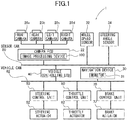
- FIG. 1 is a block diagram showing a schematic configuration of a parking assist apparatus to which an embodiment of an image processing device of the present disclosure is applied.
- FIG. 2 is a schematic view showing an example of an arrangement of cameras (i.e. front camera, rear camera, left camera, and right camera) provided to the parking assist apparatus.
- FIG. 3 is a functional block diagram showing a schematic configuration of the image processing device according to the embodiment.
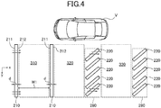
- FIG. 4 is a schematic view showing a parking space including a parking section where both sides in a vehicle width direction are partitioned by sidelines extending in a longitudinal direction of a parked vehicle, a parking section where one of the sides in the vehicle width direction is partitioned by the sideline and the other of the sides is partitioned by a diagonal line area, and a parking section where the both sides in the vehicle width direction are partitioned by the diagonal line areas.
- FIG. 5 is a flowchart showing processes for identifying the parking sections by the image processing device shown in FIG. 3 .
- FIG. 6 is a schematic view showing positive edges and negative edges of diagonal lines in the diagonal line area formed by the diagonal lines arranged parallel to each other.
- FIG. 7 is a schematic view showing line segments of the positive edges and the negative edges detected by an edge detector.
- FIG. 8 is a schematic view showing boundary line segments connecting end points of the line segments of the positive edges.
- FIG. 9 is a schematic view showing boundary line segments connecting end points of the line segments of the negative edges.
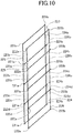
- FIG. 10 is a schematic view showing boundary lines connecting the boundary line segments.
- FIG. 11 is a schematic view corresponding to the schematic view in FIG. 4 and showing the parking section partitioned by the sidelines and the boundary lines and the parking section partitioned by the two boundary lines.
- FIG. 1 is a block diagram showing a schematic configuration of a parking assist apparatus 1 to which an embodiment of an image processing device 100 of the present disclosure is applied.
- FIG. 2 is a schematic view showing an example of arrangement of cameras 20 (i.e. front camera 20a, rear camera 20b, left camera 20c, and right camera 20d) provided to the parking assist apparatus 1.
- cameras 20 i.e. front camera 20a, rear camera 20b, left camera 20c, and right camera 20d
- a parking assist apparatus 1 shown in FIG. 1 is installed in a vehicle V shown in FIG. 2 to carry out a parking assist operation.
- the parking assist apparatus 1 is configured to detect a parking section of a parking area around the vehicle V based on images captured by the cameras (imaging devices) 20 of FIG. 2 .
- the parking assist apparatus 1 then outputs signals to allow a vehicle control unit ECU 40 to guide the vehicle V to the parking section.
- the parking assist apparatus 1 includes a front camera 20a, a rear camera 20b, a left camera 20c, and a right camera 20d as well as a camera ECU 22.
- the parking assist apparatus 1 further includes a navigation device 30, a wheel speed sensor 32, and a steering angle sensor 34.
- the front camera 20a is installed at the front bumper or the radiator grill of the vehicle V to capture an image in front of the vehicle V.
- the rear camera 20b is installed at the rear bumper or the rear garnish of the vehicle V to capture an image behind the vehicle V.
- the left camera 20c is installed at the left-wing mirror of the vehicle V to capture a side view image on the left of the vehicle V.
- the right camera 20d is installed at the right-wing mirror of the vehicle V to capture a side view image on the right of the vehicle V.
- Each of the front camera 20a, the rear camera 20b, the left camera 20c, and the right camera 20d has a wide-angle lens or a fisheye lens capable of monitoring a wide angle range such as 180 degrees.
- the parking assist apparatus 1 is able to monitor the omnidirectional area of the vehicle V including the road surface around the vehicle V.
- the four cameras 20a to 20d may collectively be referred to as the "cameras 20".
- the camera ECU 22 is configured mainly with a microcomputer including a Central Processing Unit (CPU), a Read Only Memory (ROM), a Random Access Memory (RAM), a flash memory, and the like.
- the camera ECU 22 controls the cameras 20.
- the camera ECU 22 includes the image processing device 100 configured to realize, based on the information acquired by the cameras 20, processes such as generating an overhead image and detecting a parking section.
- the navigation device 30 includes a monitor 31 to display images.
- the navigation device 30 further include a memory in which mapping data and the like is stored for navigation.
- the navigation device 30 is configured to navigate the vehicle V to a target point set by a user of the navigation device 30 based on the stored mapping data and a current position of the vehicle V detected by a GPS or the like (not illustrated).
- Various images during the navigation are displayed on the monitor 31.
- the wheel speed sensor 32 is configured to detect a wheel speed of the vehicle V.
- the wheel speed detected by the wheel speed sensor 32 is input to the vehicle control unit ECU 40, which uses the input data to control the vehicle V.
- the steering angle sensor 34 is configured to detect a steering angle of the vehicle V. When the vehicle V travels straight, the steering angle sensor 34 reads zero (0) degree (i.e. neutral position). The steering angle sensor 34 outputs a rotation angle with respect to the neutral position as the steering angle. The steering angle detected by the steering angle sensor 34 is input to the vehicle control unit ECU 40, which uses the input data to control the vehicle V.
- the parking assist apparatus 1 includes a steering control unit 50, a throttle control unit 60, and a brake control unit 70.
- the vehicle control unit ECU 40 is configured mainly with a microcomputer including a Central Processing Unit (CPU), a Read Only Memory (ROM), a Random Access Memory (RAM), a flash memory, and the like.
- the vehicle control unit ECU 40 is configured to realize various processes for assisting the vehicle V to be parked based on the information input from the camera ECU 22, the wheel speed sensor 32, and the steering angle sensor 34.
- the vehicle control unit ECU 40 realizes an automatic parking process to automatically park the vehicle V in the parking section acquired by the camera ECU 22.
- the steering control unit 50 is configured to control the drive of a steering actuator 52 and accordingly the steering angle of the vehicle V based on the information determined by the vehicle control unit ECU 40.
- the throttle control unit 60 is configured to control the drive of a throttle actuator 62 and accordingly the throttle valve of the vehicle V based on the information determined by the vehicle control unit ECU 40.
- the brake control unit 70 is configured to control the drive of a brake actuator 72 and accordingly the brake of the vehicle V based on the information determined by the vehicle control unit ECU 40.
- the camera ECU 22, the wheel speed sensor 32, and the steering angle sensor 34 are connected with the vehicle control unit ECU 40 via a sensor Controller Area Network (sensor CAN® bus) 80 using is a vehicle Local Area Network (LAN).
- sensor Controller Area Network sensor CAN® bus
- LAN vehicle Local Area Network
- the steering control unit 50, the throttle control unit 60, and the brake control unit 70 are connected with the vehicle control unit ECU 40 via a vehicle CAN® bus 82 using a vehicle LAN.
- FIG. 3 is a functional block diagram showing a schematic configuration of the image processing device 100 according to the embodiment.
- FIG. 4 is a schematic view showing the parking space including a parking section 310 where both sides in the vehicle width direction are partitioned by the sidelines 210, 210 extending in the longitudinal direction of the parked vehicle V, a parking section 320 where one of the sides in the vehicle width direction is partitioned by the sideline 210 and the other of the sides is partitioned by a diagonal line area 280, and a parking section 330 where the both sides in the vehicle width direction are partitioned by the diagonal line areas 280, 280.
- FIG. 5 is a flowchart showing processes for identifying the parking sections 310, 320, 330 by the image processing device 100 shown in FIG. 3 .
- FIG. 6 is a schematic view showing line segments 221 of the positive edges and line segments 222 of the negative edges of the diagonal lines 220 in the diagonal line area 280 which is formed by the diagonal lines 220 arranged parallel to each other.
- the image processing device 100 identifies the parking section 310, 320, or 330 shown in FIG. 4 and outputs to the vehicle controlling ECU 40 information (positions, shapes of the parking sections, etc.) related to the identified parking section 310, 320, or 330.
- the vehicle controlling ECU 40 controls the steering actuator 52, the throttle actuator 62, and controls the brake actuator 72 via the steering control unit 50, the throttle control unit 60, and the brake control unit 70, respectively in accordance with the preset program to guide the vehicle V to the identified parking section 310, 320 or 330 while monitoring the wheel speed and the steering angle detected by the wheel speed sensor 32 and the steering angle sensor 34. Thereby, the vehicle V can be properly parked in the identified parking section 310, 320, or 330.
- the parking section 310 is a parking section where both sides in the vehicle width direction are partitioned by the sidelines 210, 210 extending in the longitudinal direction of the parked vehicle V.
- the parking section 320 is a parking section where one of the sides in the vehicle width direction is partitioned by the sideline 210 and the other of the sides is partitioned by the diagonal line area 280.
- the parking section 330 is a parking section where the both sides in the vehicle width direction are partitioned by the diagonal line areas 280, 280.
- the diagonal line area 280 is an area including a plurality of diagonal lines 220 arranged parallel to each other. Each of the diagonal lines 220 is inclined with respective to the sideline 210.
- the diagonal line area 280 according to the present disclosure does not include outer lines entirely surrounding the diagonal line area 280 but includes only with the diagonal lines 220.
- the image processing device 100 includes a controller 110 and a memory 120.
- the controller 110 is mainly configured with the CPU of the camera ECU 22 and entirely controls the image processing device 100.
- the controller 110 further includes a programmable logic device such as an FPGA and arithmetic elements (i.e. integrated circuit) such as an ASIC.
- the memory 120 is mainly configured with a ROM, a RAM, a flash memory, and the like of the camera ECU 22.
- the memory 120 stores a control program (not illustrated).
- the control program is executed by the controller 110 during the startup of the image processing device 100 to allow the image processing device 100 to realize the functional configuration shown in FIG. 3 .
- the memory 120 further stores such as data of end points and the like, which are detected in the process of the controller 110, and the information related to the parking section 310.
- the image processing device 100 of the embodiment is expected to carry out high-speed processing, it is preferable to have arithmetic elements suitable for high-speed computing, such as an FPGA.
- the controller 110 includes a viewpoint converter 111, a marker detector 112, a parking section identifying portion 117, and a display controller 118.
- the viewpoint converter 111 acquires images captured by the four cameras 20 in Step S1 of FIG. 5 .
- the four cameras 20 capture images of the road surface around the vehicle V (hereinafter, the images captured by the cameras 20 are also referred to as "through images").
- the viewpoint converter 111 converts the acquired through images into overhead images similar to the view of FIG. 4 in Step S2.
- the overhead images allow the driver to look down the subject vehicle V form the air above vehicle V.
- the viewpoint converter 111 may synthesize the four overhead images which correspond to the through images captured by the four cameras 20, and generate a single overhead image around the vehicle V.
- the marker detector 112 includes an edge detector 113, a sideline detector 114, a grouping portion 115, and a boundary line setting portion 116.
- the edge detector 113 executes an edge detection process for detecting the edges extending in a direction perpendicular to an x-direction by scanning the overhead image output from the viewpoint converter 111 in a certain direction, for example, the x-direction corresponding a horizontal direction in the overhead image (S3 in FIG. 5 ).
- the x-direction corresponds to the width direction of the parking sections 310, 320, 330 in the overhead image shown in FIG. 4 .
- the edge is a portion where the brightness (pixel value (image signal value)) increases or decreases equal to or more than a predetermined value. It should be noted that the predetermined value for the positive edge and the predefined value for the negative edge may be identical to each other or may be different from each other.
- the edge may be, for example, a portion having a luminance difference (change in luminance) of eight or more on a YUV image represented by an 8-bit image signal value (0 to 255).
- a portion having a luminance difference of four or more may be set as the edge.
- the edge where the image signal value increases from a relatively small value to a relatively larger value is referred to as a positive edge.
- the edge where the image signal value decreases from the relatively large value to the relatively small value i.e. falling edge
- the edge detector 113 detects the positive edges and the negative edges.
- the sidelines 210 which are boundary lines of the parking section 310 and the diagonal lines 220 of the diagonal line area 280 are drawn or painted, for example, in white or yellow which are brighter than other portions of the road surface (i.e. with high brightness value). Accordingly, the edge detector 113 detects the positive edge at a portion shifting from the road surface without the sideline 210 or the diagonal line 220 to the sideline 210 or the diagonal line 220. Also, the edge detector 113 detects the negative edge at a portion shifting from the sideline 210 or the diagonal line 220 to the road surface without the sideline 210 or the diagonal line.
- the sidelines 210 and the diagonal lines 220 are not limited to the ones drawn or painted in white or yellow.
- the sidelines 210 and the diagonal lines 220 cannot be drawn or painted in colors darker than the portions of the road surface without the sidelines 210 and the diagonal lines 220 but may be drawn or painted in colors brighter than the portions of the road surface which do not include the sidelines 210 and the diagonal lines 220.
- the edge detector 113 executes the scanning in the x-direction a plurality of times by shifting a target to be scanned in a direction different from the scanning direction, i.e. the x-direction.
- the shifting direction may be a y-direction perpendicular to the x-direction (i.e. front and rear directions of the vehicle V parked in the parking section), for example.
- the edge detector 113 detects line segments of the positive edges extending in the predetermined direction if the positive edges are detected in a substantially straight line in the predetermined direction. This scanning process is also applied to the detection of the line segments of the negative edges.
- the edge detector 113 detects line segments 211 of the positive edges and line segments 212 of the negative edges of the sidelines 210. Also, the edge detector 113 detects line segments 221 of the positive edges and line segments 222 of the negative edges of the diagonal lines 220 in the diagonal line area 280 formed by the diagonal lines 220 arranged parallel to each other (see FIG. 6 ).
- the sideline detector 114 detects the sidelines 210 which partition the parking section 310, 320.
- the sidelines 210 extend in the longitudinal direction of the vehicle V parked in the parking section.
- the sideline detector 114 selects the line segments 211 of the positive edges and the line segments 212 of the negative edges extending in the y-direction from the line segments 211, 221 of the positive edges and the line segments 212, 222 of the negative edges detected by the edge detector 113.
- the y-direction corresponds to the longitudinal direction of the vehicle V parked in the parking section 310.
- the sideline detector 114 determines whether the selected line segments 211, 212 are paired with a predetermined distance d therebetween and longer than a predetermined length. In a case that the selected line segments 211, 212 are paired with the predetermined distance d therebetween and longer than the predetermined length (i.e. YES in S4 shown in FIG. 5 ), the sideline detector 114 detects such line segments 211, 212 as the sidelines 210 (i.e. markers) partitioning the parking section 310.
- the predetermined distance d is set to be within a range of the width of the sideline 210 generally used for the boundary line of the parking section 310.
- the predetermined distance d does not have a single value, but has values ranging from a minimum value to a maximum value.
- the predetermined length is set to be within a range of the length of the sideline 210 generally used for the boundary line of the parking section.
- the sideline detector 114 determines that the sidelines 210 do not exist on the road surface in a case where the line segments 211 of the positive edges are only detected but the line segments 212 of the negative edges which are supposed to be paired with the line segments 211 are not detected within the predetermined distance d even when the line segments 211, 212 are extending in the y-direction, for example. In this case, the sideline detector 114 does not detect the sidelines 210.
- the sideline detector 114 determines that the sidelines 210 do not exist on the road surface.
- the sideline detector 114 determines that the sidelines 210 do not exist on the road surface in a case where the line segments 212 of the negative edges are only detected, for example. As the case where the line segments 212 of the negative edges are only detected, it is assumed that the shadow of the vehicle V or the like is cast on the road surface and a portion of the road surface is shifting from the sunny side to the shadow side of the road surface, for example. In this case, the sideline detector 114 determines that the sidelines 210 do not exist on the road surface.
- the line segment 212 of the negative edge and the line segment 211 of the positive edge may be paired with the predetermined distance d therebetween.
- the shadow of the utility pole is darker than the sunny side of the road surface and recognized as a line darker than the road surface.
- the darker line is not brighter than the road surface unlike the sideline 210. Therefore, the sideline detector 114 determines that the sideline 210 does not exist on the road surface even in this case.
- the sideline detector 114 detects the sideline 210 when the line segment 212 of the negative edge exists within the predetermined distance d from the line segment 211 of the positive edge. On the other hand, the sideline detector 114 does not detect the sideline 210 even when the line segment 211 of the positive edge exists within the predetermined distance d from the line segment 212 of the negative edge. Thereby, the sideline detector 114 does not erroneously detect the darker line such as the shadow of the utility pole as the sideline 210 so that the erroneous detection of the noise can be eliminated.
- the sideline detector 114 does not detect the diagonal lines 220 inclined with respect to the y-direction (i.e. a direction perpendicular to the x-direction) as the sidelines since the sideline detector 114 detects the sidelines 210 extending in the y-direction.
- FIG. 7 is a schematic view showing the line segments 221 of the positive edges and the line segments 222 of the negative edges detected by the edge detector 113.
- FIG. 8 is a schematic view showing boundary line segments 223a, 223b, 223c, 223d connecting end points 221a of the line segments 221 of the positive edges and boundary line segments 224a, 224b, 224c, 224d connecting end points 221b of the line segments 221.
- FIG. 9 is a schematic view showing boundary line segments 225a, 225b, 225c, 225d connecting end points 222a of the line segments 222 of the negative edges and boundary line segments 226a, 226b, 226c, 226d connecting end points 222b of the line segments 222.
- FIG. 10 is a schematic view showing boundary lines 223, 224, 225, 226 connecting the boundary line segments.
- FIG. 11 corresponding to FIG. 4 is a schematic view illustrating the parking section 320 partitioned by the sideline 210 and the boundary line 223 and the parking section 330 partitioned by the two boundary lines 223, 226.
- the grouping portion 115 groups the line segments of the positive edges and the line segments of the negative edges for a positive edge group and a negative edge group by predetermined angular intervals.
- the boundary line setting portion 116 sets the boundary lines 223, 226 of the diagonal line area 280 as the markers which partition the parking sections 320, 330 based on the overhead image (see FIGS. 10 , 11 ).
- the grouping portion 115 groups the line segments 211, 221 of the positive edges and the line segments 212, 222 of the negative edges detected by the edge detector 113 for each of the line segments 211, 221 of the positive edges and the line segments 212, 222 of the negative edges by the predetermined angular intervals (e.g. angular interval of five degrees) (S7 in FIG. 5 ).
- the predetermined angular intervals e.g. angular interval of five degrees
- the grouping portion 115 groups the line segments 211, 221 of the positive edges and the line segments 212, 222 of the negative edges into groups in which the directions of the line segments are close to each other.
- the line segments extend in directions with an inclination angle ⁇ relative to the x-direction excluding a direction perpendicular to the x-direction.
- the boundary line setting portion 116 collectively groups three groups whose inclination angles ⁇ are continuous with each other out of groups grouped by the grouping portion 115.
- the three groups includes a group to which the line segments of the edges with 36 to 40 degrees of the inclination angle ⁇ belong, a group to which the line segments of the edges with 41 to 45 degrees of the inclination angle ⁇ belong, and a group to which the line segments of the edges with 46 to 50 degrees of the inclination angle ⁇ belong.
- This collective grouping of the three groups compensates the assignment of the line segments of the edges into different groups because of an improper setting of the boundaries between the groups upon grouping for example, even though the line segments of the edges should have been assigned to the same group with other line segments of the edges since the extending directions are similar to each other. If such compensation is unnecessary, the line segments of the edges belonging to the same group may be set as subjects for subsequent processes.
- the three groups include the group to which the line segments of the edges with 36 to 40 degrees of the inclination angle ⁇ belong, the group to which the line segments of the edges with 41 to 45 degrees of the inclination angle ⁇ belong, and the group to which the line segments of the edges with 46 to 50 degrees of the inclination angle ⁇ belong.
- adjacent groups whose inclination angles ⁇ are sequentially shifted are also collectively grouped into sets of three groups as described below.
- the groups of the line segments of the edges which are grouped for every five degrees of the inclination angle ⁇ are set as follows:
- sets of adjacent three groups which are collectively grouped by sequentially shifting the inclination angles ⁇ are as follows:
- the predetermined angular interval may be set to degrees smaller than five degrees such as four degrees, three degrees, or two degrees.
- the predetermined angular interval may be set to degrees larger than five degrees such as six degrees, seven degrees, or eight degrees.
- the extending directions of the line segments are relatively close to each other (difference of the inclination angles ⁇ is equal to or smaller than fifteen degrees in the present embodiment).
- the collective grouping process for adjacent three Groups Gi, G(i+1), G(i+2) is a process for extracting the line segments 221 of the positive edges and the line segments 222 of the negative edges corresponding to the diagonal lines 220 of the diagonal line area 280 which extend substantially parallel to each other.
- the grouping portion 115 groups the detected line segments 221, 222 whose inclination angles ⁇ are close to each other as shown in FIG. 6 .
- the boundary line setting portion 116 forms pairs of the line segments 221 of the positive edges from the line segments 221 belonging to the set of three groups collectively grouped with the continuous inclination angles ⁇ .
- Each of the line segments 221 includes an end point 221a at one end and an end point 221b at the other end.
- the boundary line setting portion 116 sets the boundary line segments 223a, 223b, 223c, 223d connecting the end points 221a, 221a of the paired line segments 221, 221 and the boundary line segments 224a, 224b, 224c, 224d connecting the end points 221b, 221b of the paired line segments 221, 221 as shown in FIG. 8 (S8 in FIG. 5 ).
- FIG. 8 only illustrates the boundary line segments 223a, 223b, 223c, 223d connecting the end points 221a , 221a and the boundary line segments 224a, 224b, 224c, 224d connecting the end points 221b, 221b.
- the boundary line setting portion 116 sets the boundary line segments connecting the end points 221a , 221a and the boundary line segments connecting the end points 221b, 221b with regard to all pairs of the line segments 221, 221 of the positive edge.
- the boundary line setting portion 116 also forms pairs of the line segments 222 of the negative edges from the line segments 222 belonging to the set of three groups collectively grouped. Then, the boundary line setting portion 116 sets the boundary line segments 225a, 225b, 225c, 225d connecting the end points 222a, 222a of the paired line segments 222, 222 and the boundary line segments 226a, 226b, 226c, 226d connecting the end points 222b, 222b of the paired line segments 222, 222 as shown in FIG. 9 (S8 in FIG. 5 ).
- the boundary line setting portion 116 Similar to the boundary line segments of the line segments 221, 221 of the positive edges, the boundary line setting portion 116 also sets the boundary line segments connecting the end points 222a, 222a and the boundary line segments connecting the end points 222b, 222b with regard to all pairs of the line segments 222 , 222 of the negative edges in addition to the two pairs of the line segments 222 , 222 of the negative edges shown in FIG. 9 .
- the boundary line setting portion 116 only extracts, from the boundary line segments 223a, 223b, 223c, 223d corresponding to the line segments 221 of the positive edges, the boundary line segments in which the extending directions and the lengths are substantially the same or in which the extending directions fall within a predetermined range of directions and the lengths fall within a predetermined range of lengths to remove noise components. Then, the extracted two or more boundary line segments are connected to set the boundary lines 223, 224 corresponding to the line segments 221 of the positive edges as shown in FIG. 10 . Also, the extracted two or more boundary line segments are connected to set the boundary lines 225, 226 corresponding to the line segments 222 of the negative edges as shown in FIG. 10 .
- the boundary line setting portion 116 selects the boundary lines 223, 226 whose end points are located outward of other end points in the vehicle width direction (i.e. the x-direction) from the boundary lines 223, 224 corresponding to the line segments 221 of the positive edges and the boundary lines 225, 226 corresponding to the line segments 222 of the negative edges. Then, the boundary line setting portion 116 sets the selected two boundary lines 223, 226 as the boundary lines of the diagonal line area 280 (S9 in FIG. 5 ).
- the sideline detector 114 detects the two sidelines 210, 210 partitioning the parking section 310, and the boundary line setting portion 116 sets the boundary lines 223, 226 partitioning the parking sections 320, 330.
- the parking section identifying portion 117 determines whether the distance between the two sidelines 210, 210 detected by the sideline detector 114 falls within a predetermined threshold value W1 shown in FIG. 11 . In a case that the distance between the two sidelines 210, 210 falls within the threshold value W1 (i.e. YES in S5 shown in FIG. 5 ), the parking section identifying portion 117 identifies an area between the two sidelines 210, 210 as the parking section 310 (S6 in FIG. 5 ).
- the threshold value W1 is set to have a dimension in the width direction generally set to the parking section 310 and the like.
- the parking section 320 adjacent to the parking section 310 is partitioned by the sideline 210 on one side, i.e. on the left side in the figure, but is not partitioned by the sideline 210 on the other side, i.e. on the right side in the figure. Accordingly, the parking section identifying portion 117 identifies that the parking section 320 is not the parking section partitioned by the sidelines 210, 210 on both sides (i.e. NO in S5 shown in FIG. 5 ).
- the parking section identifying portion 117 determines with regard to the parking section 320 whether the distance between the sideline 210 detected by the sideline detector 114 and the boundary line 223 set by the boundary line setting portion 116 falls within a predetermined threshold value W2 or not.
- the parking section identifying portion 117 identifies that an area between the sideline 210 and the boundary line 223 as the parking section 320 partitioned by the sideline 210 on one side and partitioned by the boundary line 223 (or the boundary line 226) on the other side (S11 shown in FIG. 5 ).
- the threshold value W2 is set to have a dimension in the width direction generally set to the parking section 320 and the like.
- the parking section identifying portion 117 determines that the parking section 330 is not the parking section partitioned by the sideline 210 on one side and partitioned by the boundary line 223 or 226 on the other side since the parking section 330 is partitioned by the boundary lines 223, 226 on either side thereof (i.e. NO in S10 shown in FIG. 5 ).
- the parking section identifying portion 117 determines with regard to the parking section 330 whether the distance between the boundary lines 223, 226 set by the boundary line setting portion 116 falls within a predetermined threshold value W3 shown in FIG. 11 .
- the parking section identifying portion 117 identifies an area between the boundary lines 223, 226 as the parking section 330 (S13 in FIG. 5 ).
- the threshold value W3 is set to have a dimension in the width direction generally set to the parking section 330 and the like.
- the parking section identifying portion 117 does not identify parking sections in a case that the parking section is not partitioned by the boundary lines 223, 226 on the both side or the distance between the boundary lines 223, 226 does not fall within the threshold value W3 (i.e. NO in S12 shown in FIG. 5 ). Then, the process is terminated (S14 in FIG. 5 ).
- the parking section identifying portion 117 identifies the parking section 310, 320, or 330 as described above, the information related to the identified parking section 310, 320, or 330 is stored in the memory 120 and output to the vehicle controlling ECU 40.
- the vehicle controlling ECU 40 After acquiring the information related to the parking section 310, 320, or 330, the vehicle controlling ECU 40 executes the automatic parking process to guide the vehicle V to the identified parking section 310, 320 or 330 and automatically park the vehicle V therein.
- the display controller 118 of the image processing device 100 displays the overhead image and the set parking section 310, 320 or 330 on the monitor 31 of the navigation device 30. Thereby, a driver can monitor the vehicle V while being guided to the parking section 310, 320 or 330.
- the image processing device 100 and the method for processing the image according to the present embodiment can properly detect the parking section 310 partitioned by the sidelines 210, the parking section 320 (adjacent to the diagonal line area 280) partitioned by the sideline 210 and the diagonal line area 280, and the parking section 330 (between the two diagonal line areas 280) partitioned by the two diagonal line area 280.
- the image processing device 100 and the method for processing the image according to the present embodiment detect the sidelines and set the boundary lines based on the overhead image acquired by executing the viewpoint conversion to the through image.
- the image processing device and the method for processing the image according to the present disclosure are not limited to the ones executing the process to the overhead image and may execute the process to the through image before the viewpoint conversion or to an image to which another process has been executed.
- the image processing device 100 includes the sideline detector 114. However, the image processing device according to the present disclosure may not include the sideline detector 114. Similarly, the method for processing the image according to the present disclosure may not detect the sidelines.
- the image processing device 100 includes the parking section identifying portion 117.
- the image processing device according to the present disclosure may not include the parking section identifying portion 117.
- the method for processing the image according to the present disclosure may not identify the parking section but only set the boundary lines.
Landscapes
- Engineering & Computer Science (AREA)
- Physics & Mathematics (AREA)
- General Physics & Mathematics (AREA)
- Multimedia (AREA)
- Theoretical Computer Science (AREA)
- Computer Vision & Pattern Recognition (AREA)
- Image Analysis (AREA)
- Traffic Control Systems (AREA)
Abstract
Description
- The present disclosure relates to an image processing device and a method for processing an image.
- A parking section detection apparatus which automatically detects a partitioned parking section for a vehicle based on an image captured by cameras is disclosed in
JP2017-024598A - Markers that partition the parking sections includes boundary lines such as white lines extending parallel to a vehicle longitudinal direction and also markers indicating areas where vehicles are prohibited to enter or park.
- For example, some parking spaces include an area formed by a plurality of diagonal lines arranged parallel to each other (hereinafter, referred to as a diagonal line area) such as a so-called zebra zone. The diagonal line area provides drivers with information that the entry and parking of the vehicles are prohibited in this area. Areas adjacent to the diagonal line area may be the parking sections.
- With regard to the white line marker extending in the longitudinal direction of the vehicle, in a case where a parking section is automatically detected based on an image captured by a camera, a signal value of the image dramatically increases at a portion shifting from a road surface with no white line to the white line while the signal value of the image dramatically decreases at a portion shifting from the white line to the road surface with no white line.
- In other words, a line segment of a rising edge (a positive edge) is detected at the portion shifting from the road surface with no white line to the white line while a line segment of a falling edge (a negative edge) is detected at the portion shifting from the white line to the road surface with no white line. When a pair of the positive edge and the negative edge are provided with a distance corresponding to the width of the white line, a portion between the pair of the positive edge and the negative edge can be detected as the white line.
- However, the diagonal line area does not include white lines extending in the vehicle longitudinal direction so that the positive edge and the negative edge cannot be detected. Therefore, the conventional process described above cannot detect the boundary lines of the parking section adjacent to the diagonal line area.
- An object of the present disclosure is to provide an image processing device and a method for processing an image that can set the boundary lines of the parking sections adjacent to the diagonal line area.
- An image processing device according to a first aspect of the present disclosure includes a camera that is mounted on a vehicle, the camera being configured to capture an image around the vehicle, an edge detector that is configured to detect, with regard to pixels in an image captured by the camera, a portion in which a luminance difference between neighboring pixels changes in a direction that increases equal to or more than a first predetermined value by calculation as a positive edge and a portion in which the luminance difference between neighboring pixels changes in a direction that decreases equal to or more than a second predetermined value by calculation as a negative edge, a grouping portion that is configured to group a plurality of the positive edges and a plurality of the negative edges detected by the edge detector into a positive edge group and a negative edge group respectively by predetermined angular intervals, and a boundary line setting portion that is configured to set, as a boundary line, a line connecting corresponding end points between the positive edges in the positive edge group or to set, as a boundary line, a line connecting corresponding end points between the negative edges in the negative edge group.
- A method for processing an image according to a second aspect of the present disclosure includes capturing an image around a vehicle by a camera that is mounted on the vehicle, detecting a portion in which an image signal value of the captured image increases equal to or more than a first predetermined value as a positive edge and a portion in which the image signal value of the captured image decreases equal to or more than a second predetermined value as a negative edge, grouping the detected positive edges and negative edges into a positive edge group and a negative edge group respectively by predetermined angular intervals, and setting, as a boundary line, a line connecting corresponding end points between the positive edges in the positive edge group or setting, as a boundary line, a line connecting corresponding end points between the negative edges in the negative edge group.
- According to the image processing device and the method for processing an image of the present disclosure, the boundary lines of the parking sections adjacent to the diagonal line area can be set properly.
-
FIG. 1 is a block diagram showing a schematic configuration of a parking assist apparatus to which an embodiment of an image processing device of the present disclosure is applied.FIG. 2 is a schematic view showing an example of an arrangement of cameras (i.e. front camera, rear camera, left camera, and right camera) provided to the parking assist apparatus.FIG. 3 is a functional block diagram showing a schematic configuration of the image processing device according to the embodiment.FIG. 4 is a schematic view showing a parking space including a parking section where both sides in a vehicle width direction are partitioned by sidelines extending in a longitudinal direction of a parked vehicle, a parking section where one of the sides in the vehicle width direction is partitioned by the sideline and the other of the sides is partitioned by a diagonal line area, and a parking section where the both sides in the vehicle width direction are partitioned by the diagonal line areas.FIG. 5 is a flowchart showing processes for identifying the parking sections by the image processing device shown inFIG. 3 .FIG. 6 is a schematic view showing positive edges and negative edges of diagonal lines in the diagonal line area formed by the diagonal lines arranged parallel to each other.FIG. 7 is a schematic view showing line segments of the positive edges and the negative edges detected by an edge detector.FIG. 8 is a schematic view showing boundary line segments connecting end points of the line segments of the positive edges.FIG. 9 is a schematic view showing boundary line segments connecting end points of the line segments of the negative edges.FIG. 10 is a schematic view showing boundary lines connecting the boundary line segments.FIG. 11 is a schematic view corresponding to the schematic view inFIG. 4 and showing the parking section partitioned by the sidelines and the boundary lines and the parking section partitioned by the two boundary lines. - With respect to the use of plural and/or singular terms herein, those having skill in the art can translate from the plural to the singular and/or from the singular to the plural as is appropriate to the context and/or application. The various singular/plural permutations may be expressly set forth herein for sake of clarity.
- Hereinafter, an embodiment of an image processing device and an image processing method according to the present disclosure will be described with reference to the drawings.
-
FIG. 1 is a block diagram showing a schematic configuration of aparking assist apparatus 1 to which an embodiment of animage processing device 100 of the present disclosure is applied.FIG. 2 is a schematic view showing an example of arrangement of cameras 20 (i.e.front camera 20a,rear camera 20b,left camera 20c, andright camera 20d) provided to theparking assist apparatus 1. - A
parking assist apparatus 1 shown inFIG. 1 is installed in a vehicle V shown inFIG. 2 to carry out a parking assist operation. Specifically, theparking assist apparatus 1 is configured to detect a parking section of a parking area around the vehicle V based on images captured by the cameras (imaging devices) 20 ofFIG. 2 . Theparking assist apparatus 1 then outputs signals to allow a vehicle control unit ECU 40 to guide the vehicle V to the parking section. - As illustrated in
FIG. 1 , theparking assist apparatus 1 includes afront camera 20a, arear camera 20b, aleft camera 20c, and aright camera 20d as well as a camera ECU 22. Theparking assist apparatus 1 further includes anavigation device 30, awheel speed sensor 32, and asteering angle sensor 34. - As illustrated in
FIG. 2 , thefront camera 20a is installed at the front bumper or the radiator grill of the vehicle V to capture an image in front of the vehicle V. Therear camera 20b is installed at the rear bumper or the rear garnish of the vehicle V to capture an image behind the vehicle V. Theleft camera 20c is installed at the left-wing mirror of the vehicle V to capture a side view image on the left of the vehicle V. Theright camera 20d is installed at the right-wing mirror of the vehicle V to capture a side view image on the right of the vehicle V. - Each of the
front camera 20a, therear camera 20b, theleft camera 20c, and theright camera 20d has a wide-angle lens or a fisheye lens capable of monitoring a wide angle range such as 180 degrees. With these fourcameras 20a-20d, theparking assist apparatus 1 is able to monitor the omnidirectional area of the vehicle V including the road surface around the vehicle V. - Hereinafter, the four
cameras 20a to 20d may collectively be referred to as the "cameras 20". - The camera ECU 22 is configured mainly with a microcomputer including a Central Processing Unit (CPU), a Read Only Memory (ROM), a Random Access Memory (RAM), a flash memory, and the like. The
camera ECU 22 controls thecameras 20. Further, the camera ECU 22 includes theimage processing device 100 configured to realize, based on the information acquired by thecameras 20, processes such as generating an overhead image and detecting a parking section. - The
navigation device 30 includes amonitor 31 to display images. Thenavigation device 30 further include a memory in which mapping data and the like is stored for navigation. Thenavigation device 30 is configured to navigate the vehicle V to a target point set by a user of thenavigation device 30 based on the stored mapping data and a current position of the vehicle V detected by a GPS or the like (not illustrated). Various images during the navigation are displayed on themonitor 31. - The
wheel speed sensor 32 is configured to detect a wheel speed of the vehicle V. The wheel speed detected by thewheel speed sensor 32 is input to the vehicle control unit ECU 40, which uses the input data to control the vehicle V. - The
steering angle sensor 34 is configured to detect a steering angle of the vehicle V. When the vehicle V travels straight, thesteering angle sensor 34 reads zero (0) degree (i.e. neutral position). Thesteering angle sensor 34 outputs a rotation angle with respect to the neutral position as the steering angle. The steering angle detected by thesteering angle sensor 34 is input to the vehiclecontrol unit ECU 40, which uses the input data to control the vehicle V. - In addition to the vehicle control unit ECU 40, the
parking assist apparatus 1 includes asteering control unit 50, athrottle control unit 60, and abrake control unit 70. - The vehicle control unit ECU 40 is configured mainly with a microcomputer including a Central Processing Unit (CPU), a Read Only Memory (ROM), a Random Access Memory (RAM), a flash memory, and the like. The vehicle control unit ECU 40 is configured to realize various processes for assisting the vehicle V to be parked based on the information input from the
camera ECU 22, thewheel speed sensor 32, and thesteering angle sensor 34. - For example, when a driver presses or touches a switch (not illustrated) to activate the
parking assist apparatus 1, the vehicle control unit ECU 40 realizes an automatic parking process to automatically park the vehicle V in the parking section acquired by the camera ECU 22. - The
steering control unit 50 is configured to control the drive of asteering actuator 52 and accordingly the steering angle of the vehicle V based on the information determined by the vehiclecontrol unit ECU 40. - The
throttle control unit 60 is configured to control the drive of athrottle actuator 62 and accordingly the throttle valve of the vehicle V based on the information determined by the vehiclecontrol unit ECU 40. - The
brake control unit 70 is configured to control the drive of abrake actuator 72 and accordingly the brake of the vehicle V based on the information determined by the vehiclecontrol unit ECU 40. - The
camera ECU 22, thewheel speed sensor 32, and thesteering angle sensor 34 are connected with the vehiclecontrol unit ECU 40 via a sensor Controller Area Network (sensor CAN® bus) 80 using is a vehicle Local Area Network (LAN). - The
steering control unit 50, thethrottle control unit 60, and thebrake control unit 70 are connected with the vehiclecontrol unit ECU 40 via a vehicle CAN® bus 82 using a vehicle LAN. -
FIG. 3 is a functional block diagram showing a schematic configuration of theimage processing device 100 according to the embodiment.FIG. 4 is a schematic view showing the parking space including aparking section 310 where both sides in the vehicle width direction are partitioned by thesidelines parking section 320 where one of the sides in the vehicle width direction is partitioned by thesideline 210 and the other of the sides is partitioned by adiagonal line area 280, and aparking section 330 where the both sides in the vehicle width direction are partitioned by thediagonal line areas -
FIG. 5 is a flowchart showing processes for identifying theparking sections image processing device 100 shown inFIG. 3 .FIG. 6 is a schematic view showingline segments 221 of the positive edges andline segments 222 of the negative edges of thediagonal lines 220 in thediagonal line area 280 which is formed by thediagonal lines 220 arranged parallel to each other. - The
image processing device 100 identifies theparking section FIG. 4 and outputs to thevehicle controlling ECU 40 information (positions, shapes of the parking sections, etc.) related to the identifiedparking section - After acquiring the information related to the identified
parking section vehicle controlling ECU 40 controls thesteering actuator 52, thethrottle actuator 62, and controls thebrake actuator 72 via thesteering control unit 50, thethrottle control unit 60, and thebrake control unit 70, respectively in accordance with the preset program to guide the vehicle V to the identifiedparking section wheel speed sensor 32 and thesteering angle sensor 34. Thereby, the vehicle V can be properly parked in the identifiedparking section - The
parking section 310 is a parking section where both sides in the vehicle width direction are partitioned by thesidelines parking section 320 is a parking section where one of the sides in the vehicle width direction is partitioned by thesideline 210 and the other of the sides is partitioned by thediagonal line area 280. Theparking section 330 is a parking section where the both sides in the vehicle width direction are partitioned by thediagonal line areas - The
diagonal line area 280 is an area including a plurality ofdiagonal lines 220 arranged parallel to each other. Each of thediagonal lines 220 is inclined with respective to thesideline 210. Thediagonal line area 280 according to the present disclosure does not include outer lines entirely surrounding thediagonal line area 280 but includes only with thediagonal lines 220. - As illustrated in
FIG. 3 , theimage processing device 100 includes acontroller 110 and amemory 120. - The
controller 110 is mainly configured with the CPU of thecamera ECU 22 and entirely controls theimage processing device 100. In addition to the CPU, thecontroller 110 further includes a programmable logic device such as an FPGA and arithmetic elements (i.e. integrated circuit) such as an ASIC. - The
memory 120 is mainly configured with a ROM, a RAM, a flash memory, and the like of thecamera ECU 22. Thememory 120 stores a control program (not illustrated). The control program is executed by thecontroller 110 during the startup of theimage processing device 100 to allow theimage processing device 100 to realize the functional configuration shown inFIG. 3 . Thememory 120 further stores such as data of end points and the like, which are detected in the process of thecontroller 110, and the information related to theparking section 310. - As the
image processing device 100 of the embodiment is expected to carry out high-speed processing, it is preferable to have arithmetic elements suitable for high-speed computing, such as an FPGA. - The
controller 110 includes aviewpoint converter 111, amarker detector 112, a parkingsection identifying portion 117, and adisplay controller 118. - The
viewpoint converter 111 acquires images captured by the fourcameras 20 in Step S1 ofFIG. 5 . The fourcameras 20 capture images of the road surface around the vehicle V (hereinafter, the images captured by thecameras 20 are also referred to as "through images"). Theviewpoint converter 111 converts the acquired through images into overhead images similar to the view ofFIG. 4 in Step S2. The overhead images allow the driver to look down the subject vehicle V form the air above vehicle V. - In addition to the viewpoint conversion, the
viewpoint converter 111 may synthesize the four overhead images which correspond to the through images captured by the fourcameras 20, and generate a single overhead image around the vehicle V. - The
marker detector 112 includes anedge detector 113, asideline detector 114, agrouping portion 115, and a boundaryline setting portion 116. - The
edge detector 113 executes an edge detection process for detecting the edges extending in a direction perpendicular to an x-direction by scanning the overhead image output from theviewpoint converter 111 in a certain direction, for example, the x-direction corresponding a horizontal direction in the overhead image (S3 inFIG. 5 ). The x-direction corresponds to the width direction of theparking sections FIG. 4 . The edge is a portion where the brightness (pixel value (image signal value)) increases or decreases equal to or more than a predetermined value. It should be noted that the predetermined value for the positive edge and the predefined value for the negative edge may be identical to each other or may be different from each other. - The edge may be, for example, a portion having a luminance difference (change in luminance) of eight or more on a YUV image represented by an 8-bit image signal value (0 to 255). In a case where the 8-bit image signal values 0 to 255 are compressed and handled in correspondence with image signal values 0 to 127, a portion having a luminance difference of four or more may be set as the edge. These values are only examples and a portion having the luminance difference greater than the above values may be set as the edge.
- Hereinafter, the edge where the image signal value increases from a relatively small value to a relatively larger value (i.e. rising edge) is referred to as a positive edge. On the other hand, the edge where the image signal value decreases from the relatively large value to the relatively small value (i.e. falling edge) is referred to as a negative edge. The
edge detector 113 detects the positive edges and the negative edges. - The
sidelines 210 which are boundary lines of theparking section 310 and thediagonal lines 220 of thediagonal line area 280 are drawn or painted, for example, in white or yellow which are brighter than other portions of the road surface (i.e. with high brightness value). Accordingly, theedge detector 113 detects the positive edge at a portion shifting from the road surface without thesideline 210 or thediagonal line 220 to thesideline 210 or thediagonal line 220. Also, theedge detector 113 detects the negative edge at a portion shifting from thesideline 210 or thediagonal line 220 to the road surface without thesideline 210 or the diagonal line. - It should be noted that the
sidelines 210 and thediagonal lines 220 are not limited to the ones drawn or painted in white or yellow. Thesidelines 210 and thediagonal lines 220 cannot be drawn or painted in colors darker than the portions of the road surface without thesidelines 210 and thediagonal lines 220 but may be drawn or painted in colors brighter than the portions of the road surface which do not include thesidelines 210 and thediagonal lines 220. - The
edge detector 113 executes the scanning in the x-direction a plurality of times by shifting a target to be scanned in a direction different from the scanning direction, i.e. the x-direction. The shifting direction may be a y-direction perpendicular to the x-direction (i.e. front and rear directions of the vehicle V parked in the parking section), for example. Theedge detector 113 detects line segments of the positive edges extending in the predetermined direction if the positive edges are detected in a substantially straight line in the predetermined direction. This scanning process is also applied to the detection of the line segments of the negative edges. - The
edge detector 113 detectsline segments 211 of the positive edges andline segments 212 of the negative edges of thesidelines 210. Also, theedge detector 113 detectsline segments 221 of the positive edges andline segments 222 of the negative edges of thediagonal lines 220 in thediagonal line area 280 formed by thediagonal lines 220 arranged parallel to each other (seeFIG. 6 ). - The
sideline detector 114 detects thesidelines 210 which partition theparking section sidelines 210 extend in the longitudinal direction of the vehicle V parked in the parking section. Specifically, thesideline detector 114 selects theline segments 211 of the positive edges and theline segments 212 of the negative edges extending in the y-direction from theline segments line segments edge detector 113. The y-direction corresponds to the longitudinal direction of the vehicle V parked in theparking section 310. - The
sideline detector 114 determines whether the selectedline segments line segments FIG. 5 ), thesideline detector 114 detectssuch line segments parking section 310. - The predetermined distance d is set to be within a range of the width of the
sideline 210 generally used for the boundary line of theparking section 310. In addition, the predetermined distance d does not have a single value, but has values ranging from a minimum value to a maximum value. Similarly, the predetermined length is set to be within a range of the length of thesideline 210 generally used for the boundary line of the parking section. - The
sideline detector 114 determines that thesidelines 210 do not exist on the road surface in a case where theline segments 211 of the positive edges are only detected but theline segments 212 of the negative edges which are supposed to be paired with theline segments 211 are not detected within the predetermined distance d even when theline segments sideline detector 114 does not detect thesidelines 210. - As such a case, it is assumed that a shadow of the vehicle V or the like is cast on the road surface and a portion of the road surface is shifting from the shadow side to a sunny side of the road surface, for example. In this shifting portion, the
line segment 211 of the positive edge is detected but theline segment 212 of the negative edge which is supposed to be paired with theline segment 211 of the positive edge is not detected. Accordingly, thesideline detector 114 determines that thesidelines 210 do not exist on the road surface. - Similarly, the
sideline detector 114 determines that thesidelines 210 do not exist on the road surface in a case where theline segments 212 of the negative edges are only detected, for example. As the case where theline segments 212 of the negative edges are only detected, it is assumed that the shadow of the vehicle V or the like is cast on the road surface and a portion of the road surface is shifting from the sunny side to the shadow side of the road surface, for example. In this case, thesideline detector 114 determines that thesidelines 210 do not exist on the road surface. - In a case where a shadow of a utility or power pole is casted on the road surface, for example, the
line segment 212 of the negative edge and theline segment 211 of the positive edge may be paired with the predetermined distance d therebetween. However, the shadow of the utility pole is darker than the sunny side of the road surface and recognized as a line darker than the road surface. In other words, the darker line is not brighter than the road surface unlike thesideline 210. Therefore, thesideline detector 114 determines that thesideline 210 does not exist on the road surface even in this case. - Specifically, the
sideline detector 114 detects thesideline 210 when theline segment 212 of the negative edge exists within the predetermined distance d from theline segment 211 of the positive edge. On the other hand, thesideline detector 114 does not detect thesideline 210 even when theline segment 211 of the positive edge exists within the predetermined distance d from theline segment 212 of the negative edge. Thereby, thesideline detector 114 does not erroneously detect the darker line such as the shadow of the utility pole as thesideline 210 so that the erroneous detection of the noise can be eliminated. - The
sideline detector 114 does not detect thediagonal lines 220 inclined with respect to the y-direction (i.e. a direction perpendicular to the x-direction) as the sidelines since thesideline detector 114 detects thesidelines 210 extending in the y-direction. -
FIG. 7 is a schematic view showing theline segments 221 of the positive edges and theline segments 222 of the negative edges detected by theedge detector 113.FIG. 8 is a schematic view showingboundary line segments end points 221a of theline segments 221 of the positive edges andboundary line segments end points 221b of theline segments 221. -
FIG. 9 is a schematic view showingboundary line segments end points 222a of theline segments 222 of the negative edges andboundary line segments end points 222b of theline segments 222.FIG. 10 is a schematic view showingboundary lines -
FIG. 11 corresponding toFIG. 4 is a schematic view illustrating theparking section 320 partitioned by thesideline 210 and theboundary line 223 and theparking section 330 partitioned by the twoboundary lines - The
grouping portion 115 groups the line segments of the positive edges and the line segments of the negative edges for a positive edge group and a negative edge group by predetermined angular intervals. The boundaryline setting portion 116 sets theboundary lines diagonal line area 280 as the markers which partition theparking sections FIGS. 10 ,11 ). - In other words, the
grouping portion 115 groups theline segments line segments edge detector 113 for each of theline segments line segments FIG. 5 ). - Specifically, the
grouping portion 115 groups theline segments line segments - Then, the boundary
line setting portion 116 collectively groups three groups whose inclination angles θ are continuous with each other out of groups grouped by thegrouping portion 115. For example, the three groups includes a group to which the line segments of the edges with 36 to 40 degrees of the inclination angle θ belong, a group to which the line segments of the edges with 41 to 45 degrees of the inclination angle θ belong, and a group to which the line segments of the edges with 46 to 50 degrees of the inclination angle θ belong. - This collective grouping of the three groups compensates the assignment of the line segments of the edges into different groups because of an improper setting of the boundaries between the groups upon grouping for example, even though the line segments of the edges should have been assigned to the same group with other line segments of the edges since the extending directions are similar to each other. If such compensation is unnecessary, the line segments of the edges belonging to the same group may be set as subjects for subsequent processes.
- As described above, the three groups include the group to which the line segments of the edges with 36 to 40 degrees of the inclination angle θ belong, the group to which the line segments of the edges with 41 to 45 degrees of the inclination angle θ belong, and the group to which the line segments of the edges with 46 to 50 degrees of the inclination angle θ belong. In addition to these three groups, adjacent groups whose inclination angles θ are sequentially shifted are also collectively grouped into sets of three groups as described below.
- For example, the groups of the line segments of the edges which are grouped for every five degrees of the inclination angle θ are set as follows:
- Group G1 to which the line segments of the edges with 1 to 5 degrees of the inclination angle θ belong
- Group G2 to which the line segments of the edges with 6 to 10 degrees of the inclination angle θ belong
- Group G3 to which the line segments of the edges with 11 to 15 degrees of the inclination angle θ belong
- Group G4 to which the line segments of the edges with 16 to 20 degrees of the inclination angle θ belong
- Group G5 to which the line segments of the edges with 21 to 25 degrees of the inclination angle θ belong
- Group G6 to which the line segments of the edges with 26 to 30 degrees of the inclination angle θ belong
- Group G7 to which the line segments of the edges with 31 to 35 degrees of the inclination angle θ belong
- Group G8 to which the line segments of the edges with 36 to 40 degrees of the inclination angle θ belong
- Group G9 to which the line segments of the edges with 41 to 45 degrees of the inclination angle θ belong
- Group G10 to which the line segments of the edges with 46 to 50 degrees of the inclination angle θ belong
- Group G11 to which the line segments of the edges with 51 to 55 degrees of the inclination angle θ belong
- Group G12 to which the line segments of the edges with 56 to 60 degrees of the inclination angle θ belong
- Group G13 to which the line segments of the edges with 61 to 65 degrees of the inclination angle θ belong
- Group G14 to which the line segments of the edges with 66 to 70 degrees of the inclination angle θ belong
- Group G15 to which the line segments of the edges with 71 to 75 degrees of the inclination angle θ belong
- Group G16 to which the line segments of the edges with 76 to 80 degrees of the inclination angle θ belong
- Group G17 to which the line segments of the edges with 81 to 85 degrees of the inclination angle θ belong
- Group G18 to which the line segments of the edges with 86 to 89 degrees of the inclination angle θ belong
- In this case, sets of adjacent three groups which are collectively grouped by sequentially shifting the inclination angles θ are as follows:
- a set of Groups G1, G2, G3
- a set of Groups G2, G3, G4
- a set of Groups G3, G4, G5
- a set of Groups G4, G5, G6
- a set of Groups G5, G6, G7
- a set of Groups G6, G7, G8
- a set of Groups G7, G8, G9
- a set of Groups G8, G9, G10
- a set of Groups G9, G10, G11
- a set of Groups G10, G11, G12
- a set of Groups G11, G12, G13
- a set of Groups G12, G13, G14
- a set of Groups G13, G14, G15
- a set of Groups G14, G15, G16
- a set of Groups G15, G16, G17
- a set of Groups G16, G17, G18
- It should be noted that the predetermined angular interval in one Group Gi (i = 1,2, ..., 18) are not limited to five degrees. For example, the predetermined angular interval may be set to degrees smaller than five degrees such as four degrees, three degrees, or two degrees. Alternatively, the predetermined angular interval may be set to degrees larger than five degrees such as six degrees, seven degrees, or eight degrees.
- In the line segments of the edges belonging to a set of three Groups Gi, G(i+1), G(i+2) collectively grouped, the extending directions of the line segments (i.e. the angle θ relative to the x-direction in
FIG. 7 ) are relatively close to each other (difference of the inclination angles θ is equal to or smaller than fifteen degrees in the present embodiment). The collective grouping process for adjacent three Groups Gi, G(i+1), G(i+2) is a process for extracting theline segments 221 of the positive edges and theline segments 222 of the negative edges corresponding to thediagonal lines 220 of thediagonal line area 280 which extend substantially parallel to each other. - Specifically, when the
edge detector 113 detects theline segments 221 of the positive edges and theline segments 222 of the negative edges extending in different directions as shown inFIG. 7 , thegrouping portion 115 groups the detectedline segments FIG. 6 . - Next, the boundary
line setting portion 116 forms pairs of theline segments 221 of the positive edges from theline segments 221 belonging to the set of three groups collectively grouped with the continuous inclination angles θ. Each of theline segments 221 includes anend point 221a at one end and anend point 221b at the other end. Then, the boundaryline setting portion 116 sets theboundary line segments end points line segments boundary line segments end points line segments FIG. 8 (S8 inFIG. 5 ). - To simplify the drawing,
FIG. 8 only illustrates theboundary line segments end points boundary line segments end points line setting portion 116 sets the boundary line segments connecting theend points end points line segments - The boundary
line setting portion 116 also forms pairs of theline segments 222 of the negative edges from theline segments 222 belonging to the set of three groups collectively grouped. Then, the boundaryline setting portion 116 sets theboundary line segments end points line segments boundary line segments end points line segments FIG. 9 (S8 inFIG. 5 ). - Similar to the boundary line segments of the
line segments line setting portion 116 also sets the boundary line segments connecting theend points end points line segments line segments FIG. 9 . - The boundary
line setting portion 116 only extracts, from theboundary line segments line segments 221 of the positive edges, the boundary line segments in which the extending directions and the lengths are substantially the same or in which the extending directions fall within a predetermined range of directions and the lengths fall within a predetermined range of lengths to remove noise components. Then, the extracted two or more boundary line segments are connected to set theboundary lines line segments 221 of the positive edges as shown inFIG. 10 . Also, the extracted two or more boundary line segments are connected to set theboundary lines line segments 222 of the negative edges as shown inFIG. 10 . - Further, the boundary
line setting portion 116 selects theboundary lines boundary lines line segments 221 of the positive edges and theboundary lines line segments 222 of the negative edges. Then, the boundaryline setting portion 116 sets the selected twoboundary lines FIG. 5 ). - With regard to the overhead image shown in
FIG. 4 , thesideline detector 114 detects the twosidelines parking section 310, and the boundaryline setting portion 116 sets theboundary lines parking sections - With regard to the
parking section 310, the parkingsection identifying portion 117 determines whether the distance between the twosidelines sideline detector 114 falls within a predetermined threshold value W1 shown inFIG. 11 . In a case that the distance between the twosidelines FIG. 5 ), the parkingsection identifying portion 117 identifies an area between the twosidelines FIG. 5 ). - It should be noted that the threshold value W1 is set to have a dimension in the width direction generally set to the
parking section 310 and the like. - The
parking section 320 adjacent to theparking section 310 is partitioned by thesideline 210 on one side, i.e. on the left side in the figure, but is not partitioned by thesideline 210 on the other side, i.e. on the right side in the figure. Accordingly, the parkingsection identifying portion 117 identifies that theparking section 320 is not the parking section partitioned by thesidelines FIG. 5 ). - Then, as shown in
FIG. 11 , the parkingsection identifying portion 117 determines with regard to theparking section 320 whether the distance between thesideline 210 detected by thesideline detector 114 and theboundary line 223 set by the boundaryline setting portion 116 falls within a predetermined threshold value W2 or not. - In a case that the distance between the
sideline 210 and theboundary line 223 falls within the threshold value W2 (i.e. YES in S10 shown inFIG. 5 ), the parkingsection identifying portion 117 identifies that an area between thesideline 210 and theboundary line 223 as theparking section 320 partitioned by thesideline 210 on one side and partitioned by the boundary line 223 (or the boundary line 226) on the other side (S11 shown inFIG. 5 ). - It should be noted that the threshold value W2 is set to have a dimension in the width direction generally set to the
parking section 320 and the like. - With regard to the
parking section 330 adjacent to theparking section 320, the parkingsection identifying portion 117 determines that theparking section 330 is not the parking section partitioned by thesideline 210 on one side and partitioned by theboundary line parking section 330 is partitioned by theboundary lines FIG. 5 ). - Then, the parking
section identifying portion 117 determines with regard to theparking section 330 whether the distance between theboundary lines line setting portion 116 falls within a predetermined threshold value W3 shown inFIG. 11 . - In a case that the distance between
boundary lines FIG. 5 ), the parkingsection identifying portion 117 identifies an area between theboundary lines FIG. 5 ). - It should be noted that the threshold value W3 is set to have a dimension in the width direction generally set to the
parking section 330 and the like. - The parking
section identifying portion 117 does not identify parking sections in a case that the parking section is not partitioned by theboundary lines boundary lines FIG. 5 ). Then, the process is terminated (S14 inFIG. 5 ). - When the parking
section identifying portion 117 identifies theparking section parking section memory 120 and output to thevehicle controlling ECU 40. - After acquiring the information related to the
parking section vehicle controlling ECU 40 executes the automatic parking process to guide the vehicle V to the identifiedparking section - In addition, the
display controller 118 of theimage processing device 100 displays the overhead image and the setparking section monitor 31 of thenavigation device 30. Thereby, a driver can monitor the vehicle V while being guided to theparking section - The
image processing device 100 and the method for processing the image according to the present embodiment can properly detect theparking section 310 partitioned by thesidelines 210, the parking section 320 (adjacent to the diagonal line area 280) partitioned by thesideline 210 and thediagonal line area 280, and the parking section 330 (between the two diagonal line areas 280) partitioned by the twodiagonal line area 280. - The
image processing device 100 and the method for processing the image according to the present embodiment detect the sidelines and set the boundary lines based on the overhead image acquired by executing the viewpoint conversion to the through image. However, the image processing device and the method for processing the image according to the present disclosure are not limited to the ones executing the process to the overhead image and may execute the process to the through image before the viewpoint conversion or to an image to which another process has been executed. - The
image processing device 100 according to the present embodiment includes thesideline detector 114. However, the image processing device according to the present disclosure may not include thesideline detector 114. Similarly, the method for processing the image according to the present disclosure may not detect the sidelines. - In addition, the
image processing device 100 according to the present embodiment includes the parkingsection identifying portion 117. However, the image processing device according to the present disclosure may not include the parkingsection identifying portion 117. Also, the method for processing the image according to the present disclosure may not identify the parking section but only set the boundary lines. - Although the present disclosure has been described in terms of an exemplary embodiment, it should not be limited thereto. It should be appreciated that variations or modifications may be made in the embodiments described by persons skilled in the art without departing from the scope of the present invention as defined by the following claims.
-
- 1
- parking assist apparatus
- 20
- camera
- 100
- image processing device
- 114
- sideline detector
- 115
- grouping portion
- 116
- boundary line setting portion
- 117
- parking section identifying portion
- 210
- sideline
- 220
- diagonal line
- 223, 226
- boundary lines
- 280
- diagonal line area
- 310, 320, 330
- parking sections
- V
- vehicle
Claims (6)
- An image processing device (100), comprising:a camera (20, 20a, 20b, 20c, 20d) that is mounted on a vehicle (V), the camera (20, 20a, 20b, 20c, 20d) being configured to capture an image around the vehicle (V);an edge detector (113) that is configured to detect, with regard to pixels in an image captured by the camera (20, 20a, 20b, 20c, 20d), a portion in which a luminance difference between neighboring pixels changes in a direction that increases equal to or more than a first predetermined value by calculation as a positive edge and a portion in which the luminance difference between neighboring pixels changes in a direction that decreases equal to or more than a second predetermined value by calculation as a negative edge;a grouping portion (115) that is configured to group a plurality of the positive edges and a plurality of the negative edges detected by the edge detector (113) into a positive edge group and a negative edge group respectively by predetermined angular intervals; anda boundary line setting portion (116) that is configured to set, as a boundary line (223, 224), a line connecting corresponding end points between the positive edges in the positive edge group or to set, as a boundary line (225, 226), a line connecting corresponding end points between the negative edges in the negative edge group.
- The image processing device (100) according to claim 1, further comprising:
a parking section identifying portion (117) that is configured to identify a parking section (310, 320, 330) by using the boundary lines (223, 224, 225, 226) set by the boundary line setting portion (116). - The image processing device (100) according to claim 2, wherein the parking section identifying portion (117) is configured to identify, as the parking section (310, 320, 330), an area between the boundary lines (223, 224, 225, 226) when a distance between the boundary lines (223, 224, 225, 226) set by the boundary line setting portion (116) falls within a predetermined threshold value.
- A method for processing an image comprising:capturing an image around a vehicle (V) by a camera (20, 20a, 20b, 20c, 20d) that is mounted on the vehicle (V);detecting a portion in which an image signal value of the captured image increases equal to or more than a first predetermined value as a positive edge and a portion in which the image signal value of the captured image decreases equal to or more than a second predetermined value as a negative edge;grouping the detected positive edges and negative edges into a positive edge group and a negative edge group respectively by predetermined angular intervals; andsetting, as a boundary line (223, 224), a line connecting corresponding end points between the positive edges in the positive edge group or setting, as a boundary line (225, 226), a line connecting corresponding end points between the negative edges in the negative edge group.
- The method according to claim 4, further comprising:
identifying a parking section (310, 320, 330) by using the set boundary lines (223, 224, 225, 226). - The method according to claim 5, wherein when a distance between the set boundary lines (223, 224, 225, 226) falls within a predetermined threshold value, an area between the boundary lines (223, 224, 225, 226) is identified as the parking section (310, 320, 330).
Applications Claiming Priority (1)
| Application Number | Priority Date | Filing Date | Title |
|---|---|---|---|
| JP2019100927A JP7341730B2 (en) | 2019-05-30 | 2019-05-30 | Image processing device and image processing method |
Publications (1)
| Publication Number | Publication Date |
|---|---|
| EP3745302A1 true EP3745302A1 (en) | 2020-12-02 |
Family
ID=70861291
Family Applications (1)
| Application Number | Title | Priority Date | Filing Date |
|---|---|---|---|
| EP20176764.7A Withdrawn EP3745302A1 (en) | 2019-05-30 | 2020-05-27 | Image processing device and method for processing image |
Country Status (4)
| Country | Link |
|---|---|
| US (1) | US11462026B2 (en) |
| EP (1) | EP3745302A1 (en) |
| JP (1) | JP7341730B2 (en) |
| CN (1) | CN112016381B (en) |
Families Citing this family (3)
| Publication number | Priority date | Publication date | Assignee | Title |
|---|---|---|---|---|
| JP7688476B2 (en) * | 2019-10-11 | 2025-06-04 | 株式会社アイシン | Parking Assistance Device |
| CN114724117B (en) * | 2022-06-07 | 2022-09-13 | 腾讯科技(深圳)有限公司 | Lane line key point data generation method and device, electronic equipment and storage medium |
| CN115311892B (en) * | 2022-08-05 | 2023-11-24 | 合众新能源汽车股份有限公司 | Parking space display method and device and electronic equipment |
Citations (4)
| Publication number | Priority date | Publication date | Assignee | Title |
|---|---|---|---|---|
| JP2011030140A (en) * | 2009-07-29 | 2011-02-10 | Hitachi Automotive Systems Ltd | External world recognition device |
| EP2927076A1 (en) * | 2012-11-27 | 2015-10-07 | Nissan Motor Co., Ltd | Acceleration suppression device for vehicles and acceleration suppression method for vehicles |
| JP2017024598A (en) | 2015-07-23 | 2017-02-02 | Kyb株式会社 | Parking guidance system |
| WO2018105179A1 (en) * | 2016-12-07 | 2018-06-14 | クラリオン株式会社 | Vehicle-mounted image processing device |
Family Cites Families (11)
| Publication number | Priority date | Publication date | Assignee | Title |
|---|---|---|---|---|
| JP3951465B2 (en) * | 1998-06-26 | 2007-08-01 | アイシン精機株式会社 | Parking assistance device |
| JP2008213647A (en) * | 2007-03-02 | 2008-09-18 | Aisin Aw Co Ltd | Parking assist method and parking assist system |
| JP2008213791A (en) * | 2007-03-07 | 2008-09-18 | Aisin Aw Co Ltd | Parking assist method and parking assist system |
| US9378425B2 (en) * | 2012-11-27 | 2016-06-28 | Clarion Co., Ltd. | On-vehicle image processing device |
| JP2014106704A (en) * | 2012-11-27 | 2014-06-09 | Clarion Co Ltd | In-vehicle image processing device |
| JP5981322B2 (en) * | 2012-11-27 | 2016-08-31 | クラリオン株式会社 | In-vehicle image processing device |
| CN105160322B (en) * | 2015-09-07 | 2018-07-24 | 北京航空航天大学 | Outdoor parking space free parking spaces recognition methods based on Aerial Images |
| JP6768275B2 (en) * | 2015-09-11 | 2020-10-14 | クラリオン株式会社 | Vehicle parking lot recognition device |
| JP6628672B2 (en) * | 2016-04-05 | 2020-01-15 | アルパイン株式会社 | Vehicle periphery display device and vehicle periphery display method |
| KR102485480B1 (en) * | 2016-05-02 | 2023-01-05 | 현대모비스 주식회사 | A method and apparatus of assisting parking by creating virtual parking lines |
| JP7203587B2 (en) * | 2018-12-14 | 2023-01-13 | 株式会社デンソーテン | Image processing device and image processing method |
-
2019
- 2019-05-30 JP JP2019100927A patent/JP7341730B2/en active Active
-
2020
- 2020-05-20 CN CN202010429769.0A patent/CN112016381B/en active Active
- 2020-05-27 EP EP20176764.7A patent/EP3745302A1/en not_active Withdrawn
- 2020-05-29 US US16/887,061 patent/US11462026B2/en active Active
Patent Citations (5)
| Publication number | Priority date | Publication date | Assignee | Title |
|---|---|---|---|---|
| JP2011030140A (en) * | 2009-07-29 | 2011-02-10 | Hitachi Automotive Systems Ltd | External world recognition device |
| EP2927076A1 (en) * | 2012-11-27 | 2015-10-07 | Nissan Motor Co., Ltd | Acceleration suppression device for vehicles and acceleration suppression method for vehicles |
| JP2017024598A (en) | 2015-07-23 | 2017-02-02 | Kyb株式会社 | Parking guidance system |
| WO2018105179A1 (en) * | 2016-12-07 | 2018-06-14 | クラリオン株式会社 | Vehicle-mounted image processing device |
| EP3553744A1 (en) * | 2016-12-07 | 2019-10-16 | Clarion Co., Ltd. | Vehicle-mounted image processing device |
Non-Patent Citations (1)
| Title |
|---|
| SUCHITRA SATHYANARAYANA: "Detection of road markings for advanced driver assistance", 1 January 2013 (2013-01-01), XP055730558, Retrieved from the Internet <URL:https://dr.ntu.edu.sg/bitstream/10356/54995/1/Suchitra%20Sathyanarayana%20Online%20PDF%20Version.pdf> [retrieved on 20200914] * |
Also Published As
| Publication number | Publication date |
|---|---|
| US20200380276A1 (en) | 2020-12-03 |
| JP7341730B2 (en) | 2023-09-11 |
| CN112016381A (en) | 2020-12-01 |
| US11462026B2 (en) | 2022-10-04 |
| CN112016381B (en) | 2024-04-02 |
| JP2020194470A (en) | 2020-12-03 |
Similar Documents
| Publication | Publication Date | Title |
|---|---|---|
| EP3933684A1 (en) | Image based detection of parking space marked by dashed lines | |
| US11462026B2 (en) | Image processing device and method for processing image | |
| EP3872697B1 (en) | Image processor and image processing method | |
| US11017246B2 (en) | Image processing device and image processing method | |
| EP3696723B1 (en) | Image processing device and image processing method | |
| JP5402828B2 (en) | Lane boundary detection device, lane boundary detection program | |
| EP2927060B1 (en) | On-vehicle image processing device | |
| EP3862920A1 (en) | Image processor and image processing method | |
| US20210357666A1 (en) | Image processor and image processing method | |
| US9990549B2 (en) | Complex marking determining device and complex marking determining method | |
| EP3731138B1 (en) | Image processing device and image processing method | |
| JP2018106259A (en) | Division line recognition device | |
| JP5034809B2 (en) | Vehicle road surface state estimating device | |
| JP7446851B2 (en) | Image processing device and image processing method | |
| JP7453008B2 (en) | Image processing device and image processing method | |
| JP6960827B2 (en) | Road surface area detector | |
| KR101396924B1 (en) | lane wideh measuring system by using cammera | |
| JPH1097699A (en) | Obstacle detection device for vehicles | |
| JP4270183B2 (en) | White line detector | |
| JPH08315116A (en) | Image processing device | |
| JP7446830B2 (en) | Image processing device and image processing method | |
| JP2005335573A (en) | Handle neutral position detection method and handle neutral position detection device | |
| JPS63163976A (en) | Recognition method for object |
Legal Events
| Date | Code | Title | Description |
|---|---|---|---|
| PUAI | Public reference made under article 153(3) epc to a published international application that has entered the european phase |
Free format text: ORIGINAL CODE: 0009012 |
|
| STAA | Information on the status of an ep patent application or granted ep patent |
Free format text: STATUS: REQUEST FOR EXAMINATION WAS MADE |
|
| 17P | Request for examination filed |
Effective date: 20200527 |
|
| AK | Designated contracting states |
Kind code of ref document: A1 Designated state(s): AL AT BE BG CH CY CZ DE DK EE ES FI FR GB GR HR HU IE IS IT LI LT LU LV MC MK MT NL NO PL PT RO RS SE SI SK SM TR |
|
| AX | Request for extension of the european patent |
Extension state: BA ME |
|
| STAA | Information on the status of an ep patent application or granted ep patent |
Free format text: STATUS: EXAMINATION IS IN PROGRESS |
|
| 17Q | First examination report despatched |
Effective date: 20220907 |
|
| REG | Reference to a national code |
Ref country code: DE Ref legal event code: R079 Free format text: PREVIOUS MAIN CLASS: G06K0009000000 Ipc: G06V0010440000 |
|
| GRAP | Despatch of communication of intention to grant a patent |
Free format text: ORIGINAL CODE: EPIDOSNIGR1 |
|
| STAA | Information on the status of an ep patent application or granted ep patent |
Free format text: STATUS: GRANT OF PATENT IS INTENDED |
|
| RIC1 | Information provided on ipc code assigned before grant |
Ipc: G06V 20/58 20220101ALI20240409BHEP Ipc: G06V 10/44 20220101AFI20240409BHEP |
|
| INTG | Intention to grant announced |
Effective date: 20240424 |
|
| RIN1 | Information on inventor provided before grant (corrected) |
Inventor name: KUBOTA, MAMORU Inventor name: KANEKO, TAKAYUKI |
|
| STAA | Information on the status of an ep patent application or granted ep patent |
Free format text: STATUS: THE APPLICATION IS DEEMED TO BE WITHDRAWN |
|
| 18D | Application deemed to be withdrawn |
Effective date: 20240827 |