EP3745202B1 - Pico projector and control method therefor; vehicle comprising the same - Google Patents
Pico projector and control method therefor; vehicle comprising the same Download PDFInfo
- Publication number
- EP3745202B1 EP3745202B1 EP20177155.7A EP20177155A EP3745202B1 EP 3745202 B1 EP3745202 B1 EP 3745202B1 EP 20177155 A EP20177155 A EP 20177155A EP 3745202 B1 EP3745202 B1 EP 3745202B1
- Authority
- EP
- European Patent Office
- Prior art keywords
- power supply
- supply unit
- dmd
- processing circuit
- pico projector
- Prior art date
- Legal status (The legal status is an assumption and is not a legal conclusion. Google has not performed a legal analysis and makes no representation as to the accuracy of the status listed.)
- Active
Links
Images


Classifications
-
- G—PHYSICS
- G03—PHOTOGRAPHY; CINEMATOGRAPHY; ANALOGOUS TECHNIQUES USING WAVES OTHER THAN OPTICAL WAVES; ELECTROGRAPHY; HOLOGRAPHY
- G03B—APPARATUS OR ARRANGEMENTS FOR TAKING PHOTOGRAPHS OR FOR PROJECTING OR VIEWING THEM; APPARATUS OR ARRANGEMENTS EMPLOYING ANALOGOUS TECHNIQUES USING WAVES OTHER THAN OPTICAL WAVES; ACCESSORIES THEREFOR
- G03B21/00—Projectors or projection-type viewers; Accessories therefor
- G03B21/005—Projectors using an electronic spatial light modulator but not peculiar thereto
- G03B21/008—Projectors using an electronic spatial light modulator but not peculiar thereto using micromirror devices
-
- B—PERFORMING OPERATIONS; TRANSPORTING
- B60—VEHICLES IN GENERAL
- B60Q—ARRANGEMENT OF SIGNALLING OR LIGHTING DEVICES, THE MOUNTING OR SUPPORTING THEREOF OR CIRCUITS THEREFOR, FOR VEHICLES IN GENERAL
- B60Q1/00—Arrangement of optical signalling or lighting devices, the mounting or supporting thereof or circuits therefor
- B60Q1/26—Arrangement of optical signalling or lighting devices, the mounting or supporting thereof or circuits therefor the devices being primarily intended to indicate the vehicle, or parts thereof, or to give signals, to other traffic
- B60Q1/32—Arrangement of optical signalling or lighting devices, the mounting or supporting thereof or circuits therefor the devices being primarily intended to indicate the vehicle, or parts thereof, or to give signals, to other traffic for indicating vehicle sides, e.g. clearance lights
- B60Q1/323—Arrangement of optical signalling or lighting devices, the mounting or supporting thereof or circuits therefor the devices being primarily intended to indicate the vehicle, or parts thereof, or to give signals, to other traffic for indicating vehicle sides, e.g. clearance lights on or for doors
-
- F—MECHANICAL ENGINEERING; LIGHTING; HEATING; WEAPONS; BLASTING
- F21—LIGHTING
- F21S—NON-PORTABLE LIGHTING DEVICES; SYSTEMS THEREOF; VEHICLE LIGHTING DEVICES SPECIALLY ADAPTED FOR VEHICLE EXTERIORS
- F21S41/00—Illuminating devices specially adapted for vehicle exteriors, e.g. headlamps
- F21S41/10—Illuminating devices specially adapted for vehicle exteriors, e.g. headlamps characterised by the light source
- F21S41/14—Illuminating devices specially adapted for vehicle exteriors, e.g. headlamps characterised by the light source characterised by the type of light source
- F21S41/141—Light emitting diodes [LED]
-
- F—MECHANICAL ENGINEERING; LIGHTING; HEATING; WEAPONS; BLASTING
- F21—LIGHTING
- F21S—NON-PORTABLE LIGHTING DEVICES; SYSTEMS THEREOF; VEHICLE LIGHTING DEVICES SPECIALLY ADAPTED FOR VEHICLE EXTERIORS
- F21S41/00—Illuminating devices specially adapted for vehicle exteriors, e.g. headlamps
- F21S41/10—Illuminating devices specially adapted for vehicle exteriors, e.g. headlamps characterised by the light source
- F21S41/14—Illuminating devices specially adapted for vehicle exteriors, e.g. headlamps characterised by the light source characterised by the type of light source
- F21S41/16—Laser light sources
-
- F—MECHANICAL ENGINEERING; LIGHTING; HEATING; WEAPONS; BLASTING
- F21—LIGHTING
- F21S—NON-PORTABLE LIGHTING DEVICES; SYSTEMS THEREOF; VEHICLE LIGHTING DEVICES SPECIALLY ADAPTED FOR VEHICLE EXTERIORS
- F21S41/00—Illuminating devices specially adapted for vehicle exteriors, e.g. headlamps
- F21S41/60—Illuminating devices specially adapted for vehicle exteriors, e.g. headlamps characterised by a variable light distribution
- F21S41/67—Illuminating devices specially adapted for vehicle exteriors, e.g. headlamps characterised by a variable light distribution by acting on reflectors
-
- G—PHYSICS
- G03—PHOTOGRAPHY; CINEMATOGRAPHY; ANALOGOUS TECHNIQUES USING WAVES OTHER THAN OPTICAL WAVES; ELECTROGRAPHY; HOLOGRAPHY
- G03B—APPARATUS OR ARRANGEMENTS FOR TAKING PHOTOGRAPHS OR FOR PROJECTING OR VIEWING THEM; APPARATUS OR ARRANGEMENTS EMPLOYING ANALOGOUS TECHNIQUES USING WAVES OTHER THAN OPTICAL WAVES; ACCESSORIES THEREFOR
- G03B21/00—Projectors or projection-type viewers; Accessories therefor
- G03B21/14—Details
- G03B21/28—Reflectors in projection beam
-
- B—PERFORMING OPERATIONS; TRANSPORTING
- B60—VEHICLES IN GENERAL
- B60Q—ARRANGEMENT OF SIGNALLING OR LIGHTING DEVICES, THE MOUNTING OR SUPPORTING THEREOF OR CIRCUITS THEREFOR, FOR VEHICLES IN GENERAL
- B60Q1/00—Arrangement of optical signalling or lighting devices, the mounting or supporting thereof or circuits therefor
- B60Q1/26—Arrangement of optical signalling or lighting devices, the mounting or supporting thereof or circuits therefor the devices being primarily intended to indicate the vehicle, or parts thereof, or to give signals, to other traffic
- B60Q1/32—Arrangement of optical signalling or lighting devices, the mounting or supporting thereof or circuits therefor the devices being primarily intended to indicate the vehicle, or parts thereof, or to give signals, to other traffic for indicating vehicle sides, e.g. clearance lights
- B60Q1/323—Arrangement of optical signalling or lighting devices, the mounting or supporting thereof or circuits therefor the devices being primarily intended to indicate the vehicle, or parts thereof, or to give signals, to other traffic for indicating vehicle sides, e.g. clearance lights on or for doors
- B60Q1/324—Arrangement of optical signalling or lighting devices, the mounting or supporting thereof or circuits therefor the devices being primarily intended to indicate the vehicle, or parts thereof, or to give signals, to other traffic for indicating vehicle sides, e.g. clearance lights on or for doors for signalling that a door is open or intended to be opened
-
- B—PERFORMING OPERATIONS; TRANSPORTING
- B60—VEHICLES IN GENERAL
- B60Q—ARRANGEMENT OF SIGNALLING OR LIGHTING DEVICES, THE MOUNTING OR SUPPORTING THEREOF OR CIRCUITS THEREFOR, FOR VEHICLES IN GENERAL
- B60Q2400/00—Special features or arrangements of exterior signal lamps for vehicles
- B60Q2400/50—Projected symbol or information, e.g. onto the road or car body
Definitions
- the invention relates to a projector and a control method therefor; more particularly, the invention relates to a pico projector and a control method therefor capable of increasing the reliability of the pico projector. Further, it relates to a vehicle comprising such a pico projector.
- the welcome light on the door of the existing vehicle may project an illumination beam and a logo beam from the door to the ground.
- the light is displayed on the ground, and when the door is closed, the light is turned off.
- the internal architecture of these designs mostly adopts light-emitting diodes (LEDs) as light sources, or a logo mask is placed on the LED, so as to display the patterned light on the ground.
- LEDs light-emitting diodes
- the welcome light can be projected to display different patterns and can even be applied to play animations or movies, the welcome light must be designed to include a pico projector.
- the power supply of the vehicle is designed to supply power to the welcome light when it is detected that the door of the vehicle is opened, and the power supplied to the welcome light is cut off when the door is detected to be turned off. Since the power supplied to the pico projector is frequently turned on or off, each micromirror on each digital micromirror device (DMD) is not in a flat-state when the door is opened or closed. This may cause damages to the DMD inside the pico projector and reduce the reliability of the pico projector installed on the door of the vehicle.
- DMD digital micromirror device
- US 2018/364474 A1 provides a display device capable of reliably moving a micromirror to a parking position when operation is stopped.
- a head-up display device drives a DMD element on the basis of electric power from a battery power supply.
- the head-up display device is provided with: a DMD controller for performing control of the DMD element on the basis of the electric power from the battery power supply; a voltage monitoring circuit for monitoring the voltage of the battery power supply; and a backup power supply for supplying power to the DMD controller as a backup of the battery power supply.
- the DMD controller moves the DMD element to the parking position on the basis of the electric power from the backup power supply.
- US 2015/194100 A1 provides a field sequential image display device with which the service life of DMD display elements can be lengthened.
- Each frame is equipped with: a display period, wherein a display control portion normally drives multiple mirrors and a lighting control portion drives a first lighting portion and a second lighting portion, thereby displaying a display image in display elements; and a non-display period, wherein the display control portion drives the multiple mirrors for a non-display period and the lighting control portion turns off the first lighting portion and the second lighting portion, and thus the display image is not displayed in the display elements.
- a control unit lowers the display period ratio, which is the ratio of the display period in each frame period.
- the invention provides a pico projector, a control method therefor to capable of improving the reliability of the pico projector installed on a door of a vehicle and a vehicle as defined respectively in independent claims 1, 11, 15
- an embodiment of the invention provides a pico projector installed on a door of a vehicle and including a light source, a digital micromirror device (DMD), a projection lens, a power supply unit, and a processing circuit.
- the light source is configured to provide an illumination beam
- the DMD is disposed on a propagation path of the illumination beam and configured to convert the illumination beam into an image beam
- the projection lens is disposed on a propagation path of the image beam and configured to project the image beam to the outside of the pico projector
- the power supply unit is coupled to the light source and the DMD
- the processing circuit is coupled to the power supply unit and the DMD.
- the processing circuit receives a shutdown warning signal and transmits a parking signal to the DMD, so as to perform a parking operation on the DMD After the processing circuit transmits the parking signal, the processing circuit notifies the power supply unit of cutting off a first power supplied to the DMD after a predetermined time interval.
- the predetermined time interval is greater than one millisecond.
- the power supply unit may be notified of cutting off a second power supplied to the light source.
- the pico projector may further comprise a transducer, coupled to the processing circuit and the power supply unit.
- the transducer may transmit the shutdown warning signal to the processing circuit.
- the power supply unit may be notified of cutting off a third power supplied to the transducer.
- the transducer may comprise at least one of a distance transducer and an ambient light transducer.
- the processing circuit may comprise a voltage detecting circuit configured to detect an input voltage of the power supply unit.
- the voltage detecting circuit may transmit the shutdown warning signal to the processing circuit.
- the vehicle having a central control system may be configured to issue the shutdown warning signal to the processing circuit after the door of the vehicle is closed.
- the central control system may supply an input voltage to the power supply unit, and after issuing the shutdown warning signal, the central control system may cut off the input voltage supplied to the power supply unit after the predetermined time interval.
- the power supply unit may receive an input voltage and may output a plurality of output voltages.
- a first capacitor may be set corresponding to the input voltage, and at least one second capacitor is set corresponding to the plurality of output voltages.
- an embodiment of the invention provides a control method for a pico projector.
- the pico projector is installed on a door of a vehicle and includes a light source, a DMD, a projection lens, a power supply unit, and a processing circuit.
- the power supply unit is coupled to the light source, the DMD, and the processing circuit.
- the processing circuit is coupled to the DMD, and the control method for the pico projector includes: providing an illumination beam by the light source, converting the illumination beam to an image beam by the DMD disposed on a propagation path of the illumination beam, projecting the image beam to the outside of the pico projector by the projection lens disposed on a propagation path of the image beam, and receiving a shutdown warning signal by the processing circuit and transmitting the parking signal to the DMD, so as to perform a parking operation on the DMD; after transmitting the parking signal, the power supply unit is notified of cutting off a first power supplied to the DMD after a predetermined time interval.
- the predetermined time interval may be greater than one millisecond.
- the processing circuit receives the shutdown warning signal, optionally notifying the power supply unit of cutting off a second power supplied to the light source.
- control method may further comprise: a transducer coupled to the processing circuit and the power supply unit.
- control method may further comprise: transmitting the shutdown warning signal to the processing circuit by the transducer when the transducer senses that the door of the vehicle is closing.
- control method may further comprise notifying the power supply unit of cutting off a third power supplied to the transducer after the processing circuit receives the shutdown warning signal.
- the processing circuit may comprise a voltage detecting circuit configured to detect an input voltage of the power supply unit.
- the voltage detecting circuit may transmit the shutdown warning signal to the processing circuit.
- the vehicle may have a central control system configured to issue the shutdown warning signal to the processing circuit after the door of the vehicle is closed.
- control method may further comprise: supplying an input voltage to the power supply unit by the central control system, and after issuing the shutdown warning signal, cutting off the input voltage supplied to the power supply unit after the predetermined time interval.
- control method may further comprise: receiving an input voltage and outputting a plurality of output voltages by the power supply unit, wherein a first capacitor is set corresponding to the input voltage, and at least one second capacitor is set corresponding to the plurality of output voltages.
- the object is also solved by a pico projector as described above.
- the processing circuit when the processing circuit receives the shutdown warning signal, the parking signal is transmitted to the DMD of the pico projector, so as to perform the parking operation on the DMD; after the parking signal is transmitted, the power supply unit is notified of cutting off the power supplied to the DMD after the predetermined time interval, so that the DMD has sufficient time for the parking operation and is not easily damaged.
- the shutdown warning signal may be generated according to the transducer detecting that the door of the vehicle is being closed, may be generated according to a voltage attenuation of an input voltage of the pico projector greater than a predetermined percentage, or may be received after a central control system of the vehicle determines that the door of the vehicle is closed.
- the pico projector may notify the power supply unit of cutting off the point power supply provided to the light source of the pico projector source and/or the transducer to save power.
- the power supply unit of the pico projector may further include at least one capacitor corresponding to the input voltage and an output voltage. As such, the DMD has more time to complete the parking operation before the power is turned off, so as to avoid damages to the DMD
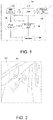
- FIG. 1 is a block diagram of a pico projector 100 according to an embodiment of the invention.
- the pico projector 100 provided in an embodiment of the invention may be installed on a door of a vehicle and project an image downward to the ground when the door is opened.
- the pico projector 100 includes a light source 110, a digital micromirror device (DMD) 120, a projection lens 130, a power supply unit 140, and a processing circuit 150.
- the light source 110 provides an illumination beam L1.
- the DMD 120 is disposed on a propagation path of the illumination beam L1 and converts the illumination beam L1 to an image beam L2.
- the projection lens 130 is disposed on a propagation path of the image beam L2 and projects the image beam L2 to the outside of the pico projector 100.
- the power supply unit 140 is coupled to the light source 110 and the DMD 120.
- the processing circuit 150 is coupled to the light source 110, the DMD 120, and the power supply unit 140.
- the light source 110 may include a plurality of visible light-emitting elements, a plurality of non-visible light-emitting elements, or a combination thereof.
- the visible light-emitting elements may include but are not limited to light-emitting diodes (LEDs) or laser diodes (LDs).
- the number of the DMDs 120 may be one or more, and the detailed steps and implementation manners corresponding to the different numbers of the DMDs 120 may be sufficiently taught or suggested by the general knowledge associated with the pertinent field and therefore will not be described again.
- the projection lens 130 is, for instance, a combination of one or more optical lenses having a diopter, such as a biconcave lens, a biconvex lens, a concave-convex lens, a convex-concave lens, a plano-convex lens, a plano-concave lens, any other non-planar lens, or a combination thereof.
- the type of the projection lens 130 is not limited herein.
- the power supply unit 140 may include a transformator, a rectifier, a voltage regulator, another similar element, processing software, or control software, which should however not be construed as a limitation herein.
- the processing circuit 150 may be, for instance, a central processing unit (CPU) or another programmable general-purpose or special-purpose microprocessor, digital signal processor (DSP), programmable controller, application specific integrated circuit (ASIC), programmable logic device (PLD), another similar device, processing software, or control software, which should however not be construed as a limitation herein.
- the processing circuit 150 may include or may work with various storage devices and peripheral circuits.
- the power supply unit 140 may provide a plurality of output voltages. Specifically, the power supply unit 140 may receive an input voltage of 12 volts (V) and output the required output voltages of 3.3V, 1.8V, 1.0V, 2.5V, etc., wherein the 2.5/1.8V output voltage may be provided to the DMD 120, and the 3.3/1.8/1.0V output voltage may be provided to the processing circuit 150.
- the processing circuit 150 may include at least one of a micro controller unit (MCU), an ASIC, and a field programmable gate array (FPGA).
- the parking operation performed on the DMD 120 may include the first step to the fifth step below, and the first step to the fifth step may be performed on the pico projector shown in FIG. 1 and FIG. 4 .
- the processing circuit 150 receives a shutdown warning signal. That is, the processing circuit 150 may determine whether the door is being closed or is about to be closed through receiving the shutdown warning signal.
- the pico projector 100 includes a transducer 160 coupled to the processing circuit 150 and the power supply unit 140.
- the transducer 160 detects that the door is closing, the transducer 160 transmits a shutdown warning signal to the processing circuit 150.
- the transducer 160 includes at least one of a distance transducer and an ambient light transducer, and the transducer 160 may be disposed on a light exit side of the pico projector 100 or near the car frame.
- the distance transducer may detect and learn that the door is closing because the detected distance is being reduced, and the ambient light transducer may detect that the door is closing because the ambient light is being weakened.
- the ambient light transducer may include a shielding structure to enhance the shading effect as within the scope of the car frame.
- the processing circuit 150 may include a voltage detection circuit configured to detect an input voltage of the power supply unit 140.
- the voltage detection circuit may be applied together with a voltage divider.
- the voltage detection circuit transmits the shutdown warning signal to the processing circuit 150.
- the voltage detection circuit detects that the input voltage is attenuated from 12V to 11V or below (e.g., the voltage attenuation is greater than a predetermined percentage of 8%)
- the voltage detection circuit transmits the shutdown warning signal to the processing circuit 150.
- the vehicle has a central control system that provides an input voltage of 12V to the power supply unit 140.
- the central control system may detect that the door of the vehicle is closing, whereby the central control system may issue the shutdown warning signal to the processing circuit 150 via a vehicle communication interface (e.g., a communication interface 170) after the door is closed.
- a vehicle communication interface e.g., a communication interface 170
- the central control system may detect that the door is closed and, after being notified of the closing of the door, transmit the shutdown warning signal to the processing circuit 150 through the vehicle communication interface.
- the vehicle communication interface is, for instance, a controller area network (CAN) bus, a universal asynchronous receiver/transmitter (UART), a local interconnect network (LIN), or any other similar interface.
- the pico projector 100 may obtain more time for performing the subsequent parking operation on DMD 120 before shut down.
- the parking operation ensures that every digital micromirror on the DMD can be parked from an off-state or an on-state to a flat-state, and the reliability of the pico projector 100 may be increased to avoid damages to the DMD 120.
- the processing circuit 150 After receiving the shutdown warning signal, the processing circuit 150 transmits a parking signal to the DMD 120 for performing the parking operation on the DMD 120.
- the parking signal is, for instance, a RESET OEZ signal.
- the processing circuit 150 may notify the power supply unit 140 of cutting off the power supplied to the light source 110 (or referred to as a second power) and notify the power supply unit 140 of cutting off the power supplied to the transducer 160 (or referred to as a third power).
- the light-emitting elements e.g., LED elements
- the light-emitting elements of the light source 110 stop receiving power supplied to a driver of the light source 110, thus causing the light-emitting elements of the light source 110 to stop providing the illumination beam L1.
- the power supply unit 140 is notified of cutting off the power (or the first power) provided to the DMD 120 after the predetermined time interval, wherein the predetermined time interval is greater than one millisecond.
- the processing circuit 150 may transmit a power cutoff signal to the power of the DMD 120 after one millisecond from transmitting the parking signal, so that the micromirror of the DMD 120 has sufficient time for the parking operation before the power is turned off. That is, the difference between the start time point of the Third Step and the start time point of the Second Step is greater than one millisecond.
- the power of the DMD 120 pulls down the voltages (e.g., V BIAS , V OFFSET , V RESET ) received by a micro-electro-mechanical system (MEMS) corresponding to the DMD 120.
- the duration during which the Fourth Step is continuously carried out is approximately 300 microseconds.
- the processing circuit 150 transmits all power disabling signals to the power supply unit 140.
- the power supply unit 140 stops providing the output voltage. Therefore, the voltages (e.g., V CC /V REF ) of the controller/integrated circuit (IC) corresponding to the DMD 120 are pulled down, and the parking operation performed on the DMD 120 is completed.
- V CC /V REF the voltages (e.g., V CC /V REF ) of the controller/integrated circuit (IC) corresponding to the DMD 120 are pulled down, and the parking operation performed on the DMD 120 is completed.
- the processing circuit 150 when the processing circuit 150 receives the shutdown warning signal provided by the transducer 160 or the shutdown warning signal provided by the central control system of the vehicle, the processing circuit 150 transmits a parking signal to the DMD 120 of the pico projector 100 to perform the parking operation on the DMD 120, and after the predetermined time interval from transmitting the parking signal, the power supply unit 140 is notified of cutting off the power supplied to the DMD 120, so that the DMD 120 has sufficient time for the parking operation and is not easily damaged.
- FIG. 2 exemplarily illustrates distance or light detection by a transducer 260 of a pico projector 200 according to an embodiment of the invention.
- the pico projector 200 includes the transducer 260 to detect ambient light, wherein the pico projector 200 includes a shielding structure disposed around the transducer 260. Therefore, an image of "ABCD" may be projected onto the ground when the door of the vehicle is opened, and the transducer 260 may detect, for instance, the projection light or the ambient light bounced off the ground.
- the surrounding shielding structure and the chassis of the vehicle may greatly block the lateral and front projection light or ambient light coming from the transducer 260; that is, the transducer 260 is shielded, so that the brightness of the ambient light detected by the transducer 260 is reduced, and the transducer 260 may transmit the shutdown warning signal to perform a shutdown procedure before the door of the vehicle is completely closed.
- the pico projector 200 stops projecting the image of "ABCD".
- the transducer 260 may be configured to detect a distance, such as detecting the distance between the door of the vehicle and the car frame or detecting the distance between the door of the vehicle and the ground.
- the distance between the transducer 260 and the chassis of the vehicle is significantly reduced, and the transducer 260 may transmit a shutdown warning signal to perform the shutdown procedure before the door is completely closed.
- the pico projector 200 stops projecting the image of "ABCD".
- FIG. 3 is a schematic diagram illustrating an input voltage of a parking operation on the DMD 120 and a discharging operation during an elapsed time period according to an embodiment of the invention.
- the processing circuit 150 receives the shutdown warning signal from the central control system of the vehicle through an input interface 170 in advance at a start time point of a time interval T0. Therefore, before the input voltage is dropped to 4.3V, the pico projector 100 has a sum time interval of the time intervals T0, T1, and T2 for performing the parking operation on the DMD 120.
- 3.3V is at least one of the input voltages of the processing circuit 150, which may be set to 3.3V plus 1V, so as to ensure that the processing circuit may still correctly process the signal within sufficient time for the parking operation.
- the processing circuit 150 obtains the shutdown warning signal at a start time point of a time interval T2 based on a voltage attenuation of the input voltage greater than a predetermined percentage (e.g., the input voltage is reduced from 12V to 11V). Therefore, before the input voltage is dropped to 4.3V, the pico projector 100 has the time interval T2 for performing the parking operation on the DMD 120.
- the time interval T2 is greater than 1.3 milliseconds, and the pico projector 100 may perform the parking operation on the DMD 120.
- 1.3 milliseconds are approximately equal to 1 millisecond required by the Second Step to the Fourth Step and 300 microseconds required by the Fourth Step.
- FIG. 4 is a block diagram of a pico projector 100 according to another embodiment of the invention.
- the pico projector 100 may further include the input interface 170 for receiving an input voltage (e.g., 12V) provided by the vehicle when the door of the vehicle is opened and providing an output voltage to other elements of the pico projector 100.
- the input interface 170 is configured to receive information from the vehicle communication interface and may also include another interface, such as a CAN bus and/or a UART, to receive signals from the host of the vehicle.
- the pico projector 100 may easily access the hardware system of the existing vehicle.
- the interfaces such as the CAN bus and/or the UART may also communicate with the processing circuit 150 through the input interface 170, so as to transmit the data of the vehicle to the processing circuit 150.
- a first capacitor 181 may be set corresponding to the input voltage of the power supply unit 140, and at least one second capacitor 182 may be set corresponding to a plurality of output voltages of the power supply unit 140.
- the pico projector 100 depicted in FIG. 1 incorporates the first capacitor 181 and at least one second capacitor 182 to form the pico projector 100 depicted in FIG. 4 , so as to extend the time intervals T1 and T2.
- the designer may select a larger capacitor depending on the actual requirements or may connect an additional capacitor in parallel to the pico projector 100, and the corresponding capacitance is 10 microfarads ( ⁇ F) or more.
- FIG. 5 is a voltage waveform diagram of a parking operation performed on a DMD 120 according to an embodiment of the invention. Please refer to FIG. 1 , FIG. 3 , and FIG. 5 at the same time.
- FIG. 5 shows the waveform diagram of RESET _ OEZ, V CC /V REF , V BIAS , V OFFSET , and V RESET in the parking operation performed on the DMD 120, wherein RESET_OEZ is active low, which may actuate a driving circuit for internal resetting V CC /V REF , so as to provide power and potential to the controller/IC that controls the DMD 120; V BIAS , V OFFSET , and V RESET respectively serve as a positive bias level, a positive offset level, and a negative reset level for the MEMS that controls the DMD 120, respectively.
- a second time point 302 a third time point 303, a fourth time point 304, and a fifth time point 305 respectively correspond to the start time point in the Second Step, the start time point in the Third Step, the start time point in the Fourth Step, and the start time point in the Fifth Step of performing the parking operation on the DMD 120.
- the Second Step includes a time interval 310 for performing the parking operation on the micromirror of the DMD 120.
- the Third Step is started to notify the power supply unit 140 of cutting off the power provided to the DMD 120.
- V BIAS i.e., after the fourth time point 304
- V OFFSET i.e., after the fourth time point 304
- V RESET i.e., after the fifth time point 305
- the power supply unit 140 stops providing the output voltage.
- the central control system may, after issuing the shutdown warning signal, wait for the predetermined time interval and then cut off the input voltage supplied to the power supply unit 140 or the input interface 170.
- the parking signal is transmitted to the DMD of the pico projector, so as to perform the parking operation on the DMD.
- the power supply unit is notified of cutting off the power supplied to the DMD after the predetermined time interval, so that the DMD has sufficient time for the parking operation and is not easily damaged.
- the shutdown warning signal may be generated according to the transducer detecting that the door is being closed, may be generated according to the voltage attenuation of the input voltage of the pico projector greater than the predetermined percentage, or may be issued through the vehicle communication interface after the central control system of the vehicle determines that the door of the vehicle is closed.
- the pico projector may notify the power supply unit of cutting off the point power supplied to the light source of the pico projector source and/or the transducer to save power.
- the power supply unit of the pico projector may further include at least one capacitor corresponding to the input voltage and an output voltage.
Landscapes
- Physics & Mathematics (AREA)
- General Physics & Mathematics (AREA)
- Engineering & Computer Science (AREA)
- General Engineering & Computer Science (AREA)
- Optics & Photonics (AREA)
- Microelectronics & Electronic Packaging (AREA)
- Mechanical Engineering (AREA)
- Projection Apparatus (AREA)
- Control Of Indicators Other Than Cathode Ray Tubes (AREA)
- Lighting Device Outwards From Vehicle And Optical Signal (AREA)
- Transforming Electric Information Into Light Information (AREA)
Description
- The invention relates to a projector and a control method therefor; more particularly, the invention relates to a pico projector and a control method therefor capable of increasing the reliability of the pico projector. Further, it relates to a vehicle comprising such a pico projector.
- The welcome light on the door of the existing vehicle may project an illumination beam and a logo beam from the door to the ground. When the door is opened, the light is displayed on the ground, and when the door is closed, the light is turned off. The internal architecture of these designs mostly adopts light-emitting diodes (LEDs) as light sources, or a logo mask is placed on the LED, so as to display the patterned light on the ground.
- If the welcome light can be projected to display different patterns and can even be applied to play animations or movies, the welcome light must be designed to include a pico projector. However, at present, the power supply of the vehicle is designed to supply power to the welcome light when it is detected that the door of the vehicle is opened, and the power supplied to the welcome light is cut off when the door is detected to be turned off. Since the power supplied to the pico projector is frequently turned on or off, each micromirror on each digital micromirror device (DMD) is not in a flat-state when the door is opened or closed. This may cause damages to the DMD inside the pico projector and reduce the reliability of the pico projector installed on the door of the vehicle.
- The information disclosed in this Background section is only for enhancement of understanding of the background of the described technology and therefore it may contain information that does not form the prior art that is already known to a person of ordinary skill in the art. Further, the information disclosed in the Background section does not mean that one or more problems to be solved by one or more embodiments of the invention were acknowledged by people of ordinary skill in the pertinent art.
-
US 2018/364474 A1 provides a display device capable of reliably moving a micromirror to a parking position when operation is stopped. A head-up display device drives a DMD element on the basis of electric power from a battery power supply. The head-up display device is provided with: a DMD controller for performing control of the DMD element on the basis of the electric power from the battery power supply; a voltage monitoring circuit for monitoring the voltage of the battery power supply; and a backup power supply for supplying power to the DMD controller as a backup of the battery power supply. When the voltage of the battery power supply which has been monitored by the voltage monitoring circuit falls to or below a threshold value, the DMD controller moves the DMD element to the parking position on the basis of the electric power from the backup power supply. -
US 2015/194100 A1 provides a field sequential image display device with which the service life of DMD display elements can be lengthened. Each frame is equipped with: a display period, wherein a display control portion normally drives multiple mirrors and a lighting control portion drives a first lighting portion and a second lighting portion, thereby displaying a display image in display elements; and a non-display period, wherein the display control portion drives the multiple mirrors for a non-display period and the lighting control portion turns off the first lighting portion and the second lighting portion, and thus the display image is not displayed in the display elements. On the basis of prescribed luminance control conditions, when the luminance of the display image is to be lower than a predetermined threshold luminance value, a control unit lowers the display period ratio, which is the ratio of the display period in each frame period. - Texas Instrument: "DLP9000 Family of 0.9 WQXGA Type A DMDs", October 2016 (2016-10), XP55724804, also presents relevant art.
- The invention provides a pico projector, a control method therefor to capable of improving the reliability of the pico projector installed on a door of a vehicle and a vehicle as defined respectively in
independent claims - Other advantages can be further illustrated by the technical features broadly embodied and described as follows.
- The object is solved by the features of the independent claims. Preferred embodiments are given in the dependent claims.
- In order to achieve one or a portion of or all of the objectives or other objectives, an embodiment of the invention provides a pico projector installed on a door of a vehicle and including a light source, a digital micromirror device (DMD), a projection lens, a power supply unit, and a processing circuit. Here, the light source is configured to provide an illumination beam, the DMD is disposed on a propagation path of the illumination beam and configured to convert the illumination beam into an image beam, the projection lens is disposed on a propagation path of the image beam and configured to project the image beam to the outside of the pico projector, the power supply unit is coupled to the light source and the DMD, and the processing circuit is coupled to the power supply unit and the DMD. The processing circuit receives a shutdown warning signal and transmits a parking signal to the DMD, so as to perform a parking operation on the DMD After the processing circuit transmits the parking signal, the processing circuit notifies the power supply unit of cutting off a first power supplied to the DMD after a predetermined time interval.
- Preferably, the predetermined time interval is greater than one millisecond.
- Preferably, after the processing circuit receives the shutdown warning signal, the power supply unit may be notified of cutting off a second power supplied to the light source.
- Preferably, the pico projector may further comprise a transducer, coupled to the processing circuit and the power supply unit.
- Preferably, when the transducer senses that the door of the vehicle is closing or closed, the transducer may transmit the shutdown warning signal to the processing circuit.
- Preferably, after the processing circuit receives the shutdown warning signal, the power supply unit may be notified of cutting off a third power supplied to the transducer.
- Preferably, the transducer may comprise at least one of a distance transducer and an ambient light transducer.
- Preferably, the processing circuit may comprise a voltage detecting circuit configured to detect an input voltage of the power supply unit.
- Preferably, when a voltage attenuation of the input voltage is greater than a predetermined percentage, the voltage detecting circuit may transmit the shutdown warning signal to the processing circuit.
- Preferably, the vehicle having a central control system may be configured to issue the shutdown warning signal to the processing circuit after the door of the vehicle is closed.
- Preferably, the central control system may supply an input voltage to the power supply unit, and after issuing the shutdown warning signal, the central control system may cut off the input voltage supplied to the power supply unit after the predetermined time interval.
- Preferably, the power supply unit may receive an input voltage and may output a plurality of output voltages.
- Preferably, a first capacitor may be set corresponding to the input voltage, and at least one second capacitor is set corresponding to the plurality of output voltages.
- To achieve one, part, or all of the foregoing purposes or other purposes, an embodiment of the invention provides a control method for a pico projector. The pico projector is installed on a door of a vehicle and includes a light source, a DMD, a projection lens, a power supply unit, and a processing circuit. The power supply unit is coupled to the light source, the DMD, and the processing circuit. The processing circuit is coupled to the DMD, and the control method for the pico projector includes: providing an illumination beam by the light source, converting the illumination beam to an image beam by the DMD disposed on a propagation path of the illumination beam, projecting the image beam to the outside of the pico projector by the projection lens disposed on a propagation path of the image beam, and receiving a shutdown warning signal by the processing circuit and transmitting the parking signal to the DMD, so as to perform a parking operation on the DMD; after transmitting the parking signal, the power supply unit is notified of cutting off a first power supplied to the DMD after a predetermined time interval.
- Preferably, the predetermined time interval may be greater than one millisecond.
- Preferably, after the processing circuit receives the shutdown warning signal, optionally notifying the power supply unit of cutting off a second power supplied to the light source.
- Preferably, the control method may further comprise: a transducer coupled to the processing circuit and the power supply unit.
- Preferably, the control method may further comprise: transmitting the shutdown warning signal to the processing circuit by the transducer when the transducer senses that the door of the vehicle is closing.
- Preferably, the control method may further comprise notifying the power supply unit of cutting off a third power supplied to the transducer after the processing circuit receives the shutdown warning signal.
- Preferably, the processing circuit may comprise a voltage detecting circuit configured to detect an input voltage of the power supply unit.
- Preferably, when a voltage attenuation of the input voltage is greater than a predetermined percentage, the voltage detecting circuit may transmit the shutdown warning signal to the processing circuit.
- Preferably, the vehicle may have a central control system configured to issue the shutdown warning signal to the processing circuit after the door of the vehicle is closed.
- Preferably, the control method may further comprise: supplying an input voltage to the power supply unit by the central control system, and after issuing the shutdown warning signal, cutting off the input voltage supplied to the power supply unit after the predetermined time interval.
- Preferably, the control method may further comprise: receiving an input voltage and outputting a plurality of output voltages by the power supply unit, wherein a first capacitor is set corresponding to the input voltage, and at least one second capacitor is set corresponding to the plurality of output voltages.
- The object is also solved by a pico projector as described above.
- Based on the above, in the pico projector and the control method therefor as provided in one or more embodiments of the invention, when the processing circuit receives the shutdown warning signal, the parking signal is transmitted to the DMD of the pico projector, so as to perform the parking operation on the DMD; after the parking signal is transmitted, the power supply unit is notified of cutting off the power supplied to the DMD after the predetermined time interval, so that the DMD has sufficient time for the parking operation and is not easily damaged. The shutdown warning signal may be generated according to the transducer detecting that the door of the vehicle is being closed, may be generated according to a voltage attenuation of an input voltage of the pico projector greater than a predetermined percentage, or may be received after a central control system of the vehicle determines that the door of the vehicle is closed. After receiving the shutdown warning signal, the pico projector may notify the power supply unit of cutting off the point power supply provided to the light source of the pico projector source and/or the transducer to save power. In addition, the power supply unit of the pico projector may further include at least one capacitor corresponding to the input voltage and an output voltage. As such, the DMD has more time to complete the parking operation before the power is turned off, so as to avoid damages to the DMD
- Other objectives, features and advantages of the invention will be further understood from the further technological features disclosed by the embodiments of the invention wherein there are shown and described preferred embodiments of this invention, simply by way of illustration of modes best suited to carry out the invention.
- The accompanying drawings are included to provide a further understanding of the invention, and are incorporated in and constitute a part of this specification. The drawings illustrate embodiments of the invention and, together with the description, serve to explain the principles of the invention.
-
FIG. 1 is a block diagram of a pico projector according to an embodiment of the invention. -
FIG. 2 exemplarily illustrates distance or light detection by a transducer of a pico projector according to an embodiment of the invention. -
FIG. 3 is a schematic diagram illustrating an input voltage of a parking operation on a digital micromirror device (DMD) and a discharging operation during an elapsed time period according to an embodiment of the invention. -
FIG. 4 is a block diagram of a pico projector according to another embodiment of the invention. -
FIG. 5 is a voltage waveform diagram of a parking operation performed on a DMD according to an embodiment of the invention. - It is to be understood that other embodiment may be utilized and structural changes may be made without departing from the scope of the present invention. Also, it is to be understood that the phraseology and terminology used herein are for the purpose of description and should not be regarded as limiting. The use of "including," "comprising," or "having" and variations thereof herein is meant to encompass the items listed thereafter and equivalents thereof as well as additional items. Unless limited otherwise, the terms "connected," "coupled," and "mounted," and variations thereof herein are used broadly and encompass direct and indirect connections, couplings, and mountings.
-
FIG. 1 is a block diagram of apico projector 100 according to an embodiment of the invention. With reference toFIG. 1 , thepico projector 100 provided in an embodiment of the invention may be installed on a door of a vehicle and project an image downward to the ground when the door is opened. Thepico projector 100 includes alight source 110, a digital micromirror device (DMD) 120, aprojection lens 130, apower supply unit 140, and aprocessing circuit 150. Thelight source 110 provides an illumination beam L1. TheDMD 120 is disposed on a propagation path of the illumination beam L1 and converts the illumination beam L1 to an image beam L2. Theprojection lens 130 is disposed on a propagation path of the image beam L2 and projects the image beam L2 to the outside of thepico projector 100. Thepower supply unit 140 is coupled to thelight source 110 and theDMD 120. Theprocessing circuit 150 is coupled to thelight source 110, theDMD 120, and thepower supply unit 140. - The
light source 110 may include a plurality of visible light-emitting elements, a plurality of non-visible light-emitting elements, or a combination thereof. The visible light-emitting elements may include but are not limited to light-emitting diodes (LEDs) or laser diodes (LDs). The number of theDMDs 120 may be one or more, and the detailed steps and implementation manners corresponding to the different numbers of theDMDs 120 may be sufficiently taught or suggested by the general knowledge associated with the pertinent field and therefore will not be described again. Theprojection lens 130 is, for instance, a combination of one or more optical lenses having a diopter, such as a biconcave lens, a biconvex lens, a concave-convex lens, a convex-concave lens, a plano-convex lens, a plano-concave lens, any other non-planar lens, or a combination thereof. The type of theprojection lens 130 is not limited herein. - The
power supply unit 140 may include a transformator, a rectifier, a voltage regulator, another similar element, processing software, or control software, which should however not be construed as a limitation herein. Theprocessing circuit 150 may be, for instance, a central processing unit (CPU) or another programmable general-purpose or special-purpose microprocessor, digital signal processor (DSP), programmable controller, application specific integrated circuit (ASIC), programmable logic device (PLD), another similar device, processing software, or control software, which should however not be construed as a limitation herein. For instance, theprocessing circuit 150 may include or may work with various storage devices and peripheral circuits. - The
power supply unit 140 may provide a plurality of output voltages. Specifically, thepower supply unit 140 may receive an input voltage of 12 volts (V) and output the required output voltages of 3.3V, 1.8V, 1.0V, 2.5V, etc., wherein the 2.5/1.8V output voltage may be provided to theDMD 120, and the 3.3/1.8/1.0V output voltage may be provided to theprocessing circuit 150. In an embodiment, theprocessing circuit 150 may include at least one of a micro controller unit (MCU), an ASIC, and a field programmable gate array (FPGA). - In an embodiment, the parking operation performed on the
DMD 120 may include the first step to the fifth step below, and the first step to the fifth step may be performed on the pico projector shown inFIG. 1 andFIG. 4 . - The
processing circuit 150 receives a shutdown warning signal. That is, theprocessing circuit 150 may determine whether the door is being closed or is about to be closed through receiving the shutdown warning signal. - In an embodiment, the
pico projector 100 includes atransducer 160 coupled to theprocessing circuit 150 and thepower supply unit 140. When thetransducer 160 detects that the door is closing, thetransducer 160 transmits a shutdown warning signal to theprocessing circuit 150. Thetransducer 160 includes at least one of a distance transducer and an ambient light transducer, and thetransducer 160 may be disposed on a light exit side of thepico projector 100 or near the car frame. Here, the distance transducer may detect and learn that the door is closing because the detected distance is being reduced, and the ambient light transducer may detect that the door is closing because the ambient light is being weakened. Preferably, the ambient light transducer may include a shielding structure to enhance the shading effect as within the scope of the car frame. - In another embodiment, the
processing circuit 150 may include a voltage detection circuit configured to detect an input voltage of thepower supply unit 140. The voltage detection circuit may be applied together with a voltage divider. When a voltage attenuation of the input voltage is greater than the predetermined percentage, the voltage detection circuit transmits the shutdown warning signal to theprocessing circuit 150. For instance, when the input voltage of thepower supply unit 140 is 12V, and the voltage detection circuit detects that the input voltage is attenuated from 12V to 11V or below (e.g., the voltage attenuation is greater than a predetermined percentage of 8%), the voltage detection circuit transmits the shutdown warning signal to theprocessing circuit 150. In an embodiment, the vehicle has a central control system that provides an input voltage of 12V to thepower supply unit 140. - In another embodiment, the central control system may detect that the door of the vehicle is closing, whereby the central control system may issue the shutdown warning signal to the
processing circuit 150 via a vehicle communication interface (e.g., a communication interface 170) after the door is closed. Specifically, the central control system may detect that the door is closed and, after being notified of the closing of the door, transmit the shutdown warning signal to theprocessing circuit 150 through the vehicle communication interface. The vehicle communication interface is, for instance, a controller area network (CAN) bus, a universal asynchronous receiver/transmitter (UART), a local interconnect network (LIN), or any other similar interface. - By issuing the shutdown warning signal earlier, the
pico projector 100 may obtain more time for performing the subsequent parking operation onDMD 120 before shut down. As such, the parking operation ensures that every digital micromirror on the DMD can be parked from an off-state or an on-state to a flat-state, and the reliability of thepico projector 100 may be increased to avoid damages to theDMD 120. - After receiving the shutdown warning signal, the
processing circuit 150 transmits a parking signal to theDMD 120 for performing the parking operation on theDMD 120. The parking signal is, for instance, a RESET OEZ signal. - In the Second Step, in order to save power consumption, the
processing circuit 150 may notify thepower supply unit 140 of cutting off the power supplied to the light source 110 (or referred to as a second power) and notify thepower supply unit 140 of cutting off the power supplied to the transducer 160 (or referred to as a third power). - In the Second Step, the light-emitting elements (e.g., LED elements) of the
light source 110 stop receiving power supplied to a driver of thelight source 110, thus causing the light-emitting elements of thelight source 110 to stop providing the illumination beam L1. - After the
processing circuit 150 transmits the parking signal, thepower supply unit 140 is notified of cutting off the power (or the first power) provided to theDMD 120 after the predetermined time interval, wherein the predetermined time interval is greater than one millisecond. For instance, theprocessing circuit 150 may transmit a power cutoff signal to the power of theDMD 120 after one millisecond from transmitting the parking signal, so that the micromirror of theDMD 120 has sufficient time for the parking operation before the power is turned off. That is, the difference between the start time point of the Third Step and the start time point of the Second Step is greater than one millisecond. - The power of the
DMD 120 pulls down the voltages (e.g., VBIAS, VOFFSET, VRESET) received by a micro-electro-mechanical system (MEMS) corresponding to theDMD 120. The duration during which the Fourth Step is continuously carried out is approximately 300 microseconds. - In the Fourth Step, the
processing circuit 150 transmits all power disabling signals to thepower supply unit 140. - The
power supply unit 140 stops providing the output voltage. Therefore, the voltages (e.g., VCC/VREF) of the controller/integrated circuit (IC) corresponding to theDMD 120 are pulled down, and the parking operation performed on theDMD 120 is completed. - Through the above five steps, when the
processing circuit 150 receives the shutdown warning signal provided by thetransducer 160 or the shutdown warning signal provided by the central control system of the vehicle, theprocessing circuit 150 transmits a parking signal to theDMD 120 of thepico projector 100 to perform the parking operation on theDMD 120, and after the predetermined time interval from transmitting the parking signal, thepower supply unit 140 is notified of cutting off the power supplied to theDMD 120, so that theDMD 120 has sufficient time for the parking operation and is not easily damaged. - The specific manner in which the
transducer 160 is configured may be referred to as what is illustrated inFIG. 2. FIG. 2 exemplarily illustrates distance or light detection by atransducer 260 of apico projector 200 according to an embodiment of the invention. Thepico projector 200 includes thetransducer 260 to detect ambient light, wherein thepico projector 200 includes a shielding structure disposed around thetransducer 260. Therefore, an image of "ABCD" may be projected onto the ground when the door of the vehicle is opened, and thetransducer 260 may detect, for instance, the projection light or the ambient light bounced off the ground. When the door is closing, the surrounding shielding structure and the chassis of the vehicle (e.g., the car frame) may greatly block the lateral and front projection light or ambient light coming from thetransducer 260; that is, thetransducer 260 is shielded, so that the brightness of the ambient light detected by thetransducer 260 is reduced, and thetransducer 260 may transmit the shutdown warning signal to perform a shutdown procedure before the door of the vehicle is completely closed. Accordingly, thepico projector 200 stops projecting the image of "ABCD". On the other hand, thetransducer 260 may be configured to detect a distance, such as detecting the distance between the door of the vehicle and the car frame or detecting the distance between the door of the vehicle and the ground. When the door is about to close, the distance between thetransducer 260 and the chassis of the vehicle (such as the car frame) is significantly reduced, and thetransducer 260 may transmit a shutdown warning signal to perform the shutdown procedure before the door is completely closed. Thus, thepico projector 200 stops projecting the image of "ABCD". -
FIG. 3 is a schematic diagram illustrating an input voltage of a parking operation on theDMD 120 and a discharging operation during an elapsed time period according to an embodiment of the invention. With reference toFIG. 1 andFIG. 3 simultaneously, in an embodiment, theprocessing circuit 150 receives the shutdown warning signal from the central control system of the vehicle through aninput interface 170 in advance at a start time point of a time interval T0. Therefore, before the input voltage is dropped to 4.3V, thepico projector 100 has a sum time interval of the time intervals T0, T1, and T2 for performing the parking operation on theDMD 120. Here, 3.3V is at least one of the input voltages of theprocessing circuit 150, which may be set to 3.3V plus 1V, so as to ensure that the processing circuit may still correctly process the signal within sufficient time for the parking operation. - In another embodiment, the
processing circuit 150 obtains the shutdown warning signal at a start time point of a time interval T2 based on a voltage attenuation of the input voltage greater than a predetermined percentage (e.g., the input voltage is reduced from 12V to 11V). Therefore, before the input voltage is dropped to 4.3V, thepico projector 100 has the time interval T2 for performing the parking operation on theDMD 120. Preferably, the time interval T2 is greater than 1.3 milliseconds, and thepico projector 100 may perform the parking operation on theDMD 120. Here, 1.3 milliseconds are approximately equal to 1 millisecond required by the Second Step to the Fourth Step and 300 microseconds required by the Fourth Step. -
FIG. 4 is a block diagram of apico projector 100 according to another embodiment of the invention. With reference toFIG. 4 , thepico projector 100 may further include theinput interface 170 for receiving an input voltage (e.g., 12V) provided by the vehicle when the door of the vehicle is opened and providing an output voltage to other elements of thepico projector 100. Theinput interface 170 is configured to receive information from the vehicle communication interface and may also include another interface, such as a CAN bus and/or a UART, to receive signals from the host of the vehicle. By modularizing theinput interface 170, thepico projector 100 may easily access the hardware system of the existing vehicle. In addition, the interfaces such as the CAN bus and/or the UART may also communicate with theprocessing circuit 150 through theinput interface 170, so as to transmit the data of the vehicle to theprocessing circuit 150. - Please refer to
FIG. 4 again. In order to extend the time of discharging the input voltage and the output voltage of the power supply unit 140 (i.e., the time interval T1 during which the voltage is dropped to 4.3V from 12V and the time interval T2), afirst capacitor 181 may be set corresponding to the input voltage of thepower supply unit 140, and at least onesecond capacitor 182 may be set corresponding to a plurality of output voltages of thepower supply unit 140. It will be understood by those skilled in the art that thepico projector 100 depicted inFIG. 1 incorporates thefirst capacitor 181 and at least onesecond capacitor 182 to form thepico projector 100 depicted inFIG. 4 , so as to extend the time intervals T1 and T2. In one embodiment, the designer may select a larger capacitor depending on the actual requirements or may connect an additional capacitor in parallel to thepico projector 100, and the corresponding capacitance is 10 microfarads (µF) or more. -
FIG. 5 is a voltage waveform diagram of a parking operation performed on aDMD 120 according to an embodiment of the invention. Please refer toFIG. 1 ,FIG. 3 , andFIG. 5 at the same time.FIG. 5 shows the waveform diagram of RESET_OEZ, VCC/VREF, VBIAS, VOFFSET, and VRESET in the parking operation performed on theDMD 120, wherein RESET_OEZ is active low, which may actuate a driving circuit for internal resetting VCC/VREF , so as to provide power and potential to the controller/IC that controls theDMD 120; VBIAS, VOFFSET, and VRESET respectively serve as a positive bias level, a positive offset level, and a negative reset level for the MEMS that controls theDMD 120, respectively. The detailed descriptions and operations of the voltages may be found in the technical documentation DLPS076a provided by Texas Instruments. The above signals have been described in the previous paragraphs and therefore will not be described hereinafter. In particular, asecond time point 302, athird time point 303, afourth time point 304, and afifth time point 305 respectively correspond to the start time point in the Second Step, the start time point in the Third Step, the start time point in the Fourth Step, and the start time point in the Fifth Step of performing the parking operation on theDMD 120. In particular, the Second Step includes atime interval 310 for performing the parking operation on the micromirror of theDMD 120. When the parking operation ends, the Third Step is started to notify thepower supply unit 140 of cutting off the power provided to theDMD 120. Next, in the Fourth Step, i.e., after thefourth time point 304, VBIAS, VOFFSET, and VRESET are pulled down. Finally, after thefifth time point 305, thepower supply unit 140 stops providing the output voltage. - In the Fifth Step, note that the central control system may, after issuing the shutdown warning signal, wait for the predetermined time interval and then cut off the input voltage supplied to the
power supply unit 140 or theinput interface 170. - To sum up, in the pico projector and the control method therefor as provided in one or more embodiments of the invention, when the shutdown warning signal is received, the parking signal is transmitted to the DMD of the pico projector, so as to perform the parking operation on the DMD. After the parking signal is transmitted, the power supply unit is notified of cutting off the power supplied to the DMD after the predetermined time interval, so that the DMD has sufficient time for the parking operation and is not easily damaged. The shutdown warning signal may be generated according to the transducer detecting that the door is being closed, may be generated according to the voltage attenuation of the input voltage of the pico projector greater than the predetermined percentage, or may be issued through the vehicle communication interface after the central control system of the vehicle determines that the door of the vehicle is closed. After receiving the shutdown warning signal, the pico projector may notify the power supply unit of cutting off the point power supplied to the light source of the pico projector source and/or the transducer to save power. In addition, the power supply unit of the pico projector may further include at least one capacitor corresponding to the input voltage and an output voltage. As such, the DMD has more time to complete the parking operation before the power is turned off, so as to avoid damages to the DMD
- The foregoing description of the preferred embodiments of the invention has been presented for purposes of illustration and description.
Claims (15)
- A pico projector for being installed on a door of a vehicle and comprising:a light source (110), configured to provide an illumination beam (L1),a digital micromirror device (DMD), disposed on a propagation path of the illumination beam (L1) and configured to convert the illumination beam (L1) to an image beam (L2),a projection lens (130), disposed on a propagation path of the image beam (L2) and configured to project the image beam (L2) to the outside of the pico projector (100),a power supply unit (140), coupled to the light source (110) and the digital micromirror device (DMD), anda processing circuit (150), coupled to the power supply unit (140) and the digital micromirror device (DMD),characterized in that the processing circuit (150) is configured to receive a shutdown warning signal, to transmit a parking signal to the digital micromirror device (DMD) to perform a parking operation on the digital micromirror device (DMD), and to notify the power supply unit (140) of cutting off a first power supplied to the digital micromirror device (DMD) after a predetermined time interval from transmitting the parking signal.
- The pico projector according to claim 1, wherein the predetermined time interval is greater than one millisecond.
- The pico projector according to claim 1 or 2, wherein after the processing circuit (150) receives the shutdown warning signal, the power supply unit (140) is notified of cutting off a second power supplied to the light source (110).
- The pico projector according to any one of claims 1 - 3, further comprising a transducer (160), coupled to the processing circuit (150) and the power supply unit (140), wherein the transducer (160) is configured to sense that the door of the vehicle is closing or closed and to transmit the shutdown warning signal to the processing circuit (150).
- The pico projector according to claim 4, wherein after the processing circuit (150) receives the shutdown warning signal, the power supply unit (140) is notified of cutting off a third power supplied to the transducer (160).
- The pico projector according to claim 4 or 5, the transducer (160) comprising at least one of a distance transducer and an ambient light transducer.
- The pico projector according to any one of claims 1 - 3, wherein the processing circuit (150) comprises a voltage detecting circuit configured to detect an input voltage of the power supply unit (140), and when a voltage attenuation of the input voltage is greater than a predetermined percentage, the voltage detecting circuit is configured to transmit the shutdown warning signal to the processing circuit (150).
- The pico projector according to any one of the preceding claims, wherein the shutdown warning signal is received at the processing circuit (150) from a central control system of the vehicle after the door of the vehicle is closed.
- The pico projector according to claim 8, wherein an input voltage is supplied from a central control system of the vehicle to the power supply unit (140), wherein after receiving the shutdown warning signal the input voltage supplied to the power supply unit (140) is cut off by the central control system after the predetermined time interval.
- The pico projector according to any one of the preceding claims, wherein the power supply unit (140) is configured to receive an input voltage and to output a plurality of output voltages, wherein a first capacitor (181) is set corresponding to the input voltage, and at least one second capacitor (182) is set corresponding to the plurality of output voltages.
- A control method for a pico projector as claimed in claim 1, the pico projector (100) being installed on a door of a vehicle and comprising a light source (110), a digital micromirror device (DMD), a projection lens, a power supply unit (140), and a processing circuit (150), the power supply unit (140) being coupled to the light source (110), the digital micromirror device (DMD), and the processing circuit (150), the processing circuit (150) being coupled to the digital micromirror device (DMD), the control method comprising:providing an illumination beam (L1) by the light source (110);converting the illumination beam (L1) to an image beam (L2) by the digital micromirror device (DMD) disposed on a propagation path of the illumination beam (LI); andprojecting the image beam (L2) to the outside of the pico projector (100) by the projection lens (130) disposed on a propagation path of the image beam (L2);characterized in that the control method further comprising:receiving a shutdown warning signal by the processing circuit (150),transmitting a parking signal to the digital micromirror device (DMD) to perform a parking operation on the digital micromirror device (DMD), andnotifying the power supply unit (140) of cutting off a first power supplied to the digital micromirror device (DMD) after a predetermined time interval from transmitting the parking signal.
- The control method according to claim 11, further comprising:
after the processing circuit receives the shutdown warning signal, notifying the power supply unit (140) of cutting off a second power supplied to the light source (110). - The control method according to claim 11 or 12, further comprising:
notifying the power supply unit (140) of cutting off a third power supplied to a transducer (160) after the processing circuit (150) receives the shutdown warning signal. - The control method according to claim 11, 12 or 13, further comprising:supplying an input voltage to the power supply unit (140) by a central control system of the vehicle, andafter issuing the shutdown warning signal, cutting off the input voltage supplied to the power supply unit (140) after the predetermined time interval; and/orreceiving an input voltage and outputting a plurality of output voltages by the power supply unit (140),setting a first capacitor corresponding to the input voltage andsetting at least one second capacitor corresponding to the plurality of output voltages.
- Vehicle comprising a door, wherein a pico projector as claimed in any one of the claims 1-10 is installed on the door.
Applications Claiming Priority (2)
| Application Number | Priority Date | Filing Date | Title |
|---|---|---|---|
| US201962853724P | 2019-05-29 | 2019-05-29 | |
| CN201911015584.9A CN112015032B (en) | 2019-05-29 | 2019-10-24 | Micro projector and micro projector control method |
Publications (2)
| Publication Number | Publication Date |
|---|---|
| EP3745202A1 EP3745202A1 (en) | 2020-12-02 |
| EP3745202B1 true EP3745202B1 (en) | 2022-04-06 |
Family
ID=70435834
Family Applications (1)
| Application Number | Title | Priority Date | Filing Date |
|---|---|---|---|
| EP20177155.7A Active EP3745202B1 (en) | 2019-05-29 | 2020-05-28 | Pico projector and control method therefor; vehicle comprising the same |
Country Status (4)
| Country | Link |
|---|---|
| US (1) | US11054726B2 (en) |
| EP (1) | EP3745202B1 (en) |
| JP (1) | JP2020194162A (en) |
| CN (2) | CN210465970U (en) |
Families Citing this family (7)
| Publication number | Priority date | Publication date | Assignee | Title |
|---|---|---|---|---|
| CN210465970U (en) * | 2019-05-29 | 2020-05-05 | 中强光电股份有限公司 | pico projector |
| WO2021187462A1 (en) * | 2020-03-17 | 2021-09-23 | 日本精機株式会社 | Head-up display device |
| CN114077133B (en) | 2020-08-12 | 2023-05-26 | 中强光电股份有限公司 | Projection device and control method thereof |
| CN112383761B (en) * | 2020-11-10 | 2021-12-10 | 青岛海信激光显示股份有限公司 | Projection apparatus and control method thereof |
| KR20240019288A (en) * | 2021-07-05 | 2024-02-14 | 가부시키가이샤 니콘 | Exposure apparatus, exposure method, and manufacturing method of electronic device |
| CN117716289A (en) * | 2021-07-28 | 2024-03-15 | 马克·W·福勒 | System for projecting images into a body of water |
| JP2024057776A (en) * | 2022-10-13 | 2024-04-25 | セイコーエプソン株式会社 | projector |
Family Cites Families (14)
| Publication number | Priority date | Publication date | Assignee | Title |
|---|---|---|---|---|
| JP3926871B2 (en) * | 1995-09-11 | 2007-06-06 | テキサス インスツルメンツ インコーポレイテツド | Digital micromirror reset method |
| US5706123A (en) * | 1996-09-27 | 1998-01-06 | Texas Instruments Incorporated | Switched control signals for digital micro-mirror device with split reset |
| TWI255389B (en) * | 2004-09-15 | 2006-05-21 | Coretronic Corp | Projector protection apparatus and protection method thereor |
| US7515324B2 (en) * | 2006-10-17 | 2009-04-07 | Texas Instruments Incorporated | System and method for resolving reset conflicts in a phased-reset spatial light modulator system |
| JP5098658B2 (en) | 2008-01-18 | 2012-12-12 | カシオ計算機株式会社 | Projection apparatus, projection control method, and program |
| JP5533537B2 (en) | 2010-10-12 | 2014-06-25 | セイコーエプソン株式会社 | Projection type display device and control method thereof |
| CN202713526U (en) * | 2012-06-12 | 2013-01-30 | 华东师范大学 | Intelligent digital micromirror driving sequence configuration apparatus |
| JP5998681B2 (en) | 2012-07-03 | 2016-09-28 | 日本精機株式会社 | Field sequential image display device |
| CN103000140B (en) * | 2012-11-23 | 2014-11-26 | 合肥工业大学 | LED (Light Emitting Diode) light source dynamic control method used for DLP (Digital Light Procession) projection |
| ES2561133B1 (en) * | 2014-07-24 | 2016-12-01 | Alejandro Rodriguez Barros | MULTIFUNCTION OUTDOOR REAR VIEW MIRROR WITH LASER ISSUED DEVICE |
| JP6106233B2 (en) * | 2015-09-08 | 2017-03-29 | 株式会社東海理化電機製作所 | Vehicle visual recognition device |
| WO2017104566A1 (en) * | 2015-12-18 | 2017-06-22 | 日本精機株式会社 | Display device |
| JP6707953B2 (en) * | 2016-03-31 | 2020-06-10 | セイコーエプソン株式会社 | Projector and projector control method |
| CN210465970U (en) * | 2019-05-29 | 2020-05-05 | 中强光电股份有限公司 | pico projector |
-
2019
- 2019-10-24 CN CN201921794342.XU patent/CN210465970U/en not_active Withdrawn - After Issue
- 2019-10-24 CN CN201911015584.9A patent/CN112015032B/en active Active
-
2020
- 2020-05-27 US US16/885,256 patent/US11054726B2/en active Active
- 2020-05-28 EP EP20177155.7A patent/EP3745202B1/en active Active
- 2020-05-28 JP JP2020092829A patent/JP2020194162A/en active Pending
Also Published As
| Publication number | Publication date |
|---|---|
| US11054726B2 (en) | 2021-07-06 |
| CN112015032A (en) | 2020-12-01 |
| US20200379322A1 (en) | 2020-12-03 |
| EP3745202A1 (en) | 2020-12-02 |
| CN112015032B (en) | 2021-12-28 |
| JP2020194162A (en) | 2020-12-03 |
| CN210465970U (en) | 2020-05-05 |
Similar Documents
| Publication | Publication Date | Title |
|---|---|---|
| EP3745202B1 (en) | Pico projector and control method therefor; vehicle comprising the same | |
| CN206884861U (en) | A kind of pixel type self-adapted car headlamp control system based on DLP | |
| US20180222378A1 (en) | Car light system and motor vehicle | |
| WO2019184837A1 (en) | Control method for on-board display device, and control device | |
| CN111354285A (en) | Circuit device, electronic apparatus, and moving object | |
| US20190204592A1 (en) | Projection display device, and operation method and operation program for projection display device | |
| US11032526B2 (en) | Projection device, projection method and projection system | |
| US20150268548A1 (en) | Method for displaying image using projector and wearable electronic device for implementing the same | |
| CN106573575A (en) | Electronic mirror device | |
| KR101679881B1 (en) | An indoor system in vehicle which having a function of assistance for make-up of user's face | |
| US7919742B2 (en) | Projector having a light intensity control unit for controlling light intensity of projected light and control method of projector | |
| KR100821757B1 (en) | Display system and its power control method | |
| CN210139814U (en) | Dynamic carpet lamp control system | |
| CN117880474A (en) | Brightness control method, display device, storage medium, and vehicle | |
| CN217361091U (en) | Laser projection equipment | |
| CN211720664U (en) | Projection apparatus and projection system | |
| JP2020194117A (en) | Virtual image display device | |
| EP3742726B1 (en) | Projection device, projection method and projection system | |
| JP7099044B2 (en) | Head-up display device | |
| US11871162B2 (en) | Projection system and operation method thereof | |
| CN108725199A (en) | A kind of display system, method and application based on speech control | |
| CN107310477A (en) | A kind of method and system for improving car-mounted display equipment safety in utilization | |
| JP2022039607A (en) | Projectors, interactive systems, projection methods and programs | |
| CN116442919A (en) | Control method and device for projection key, key equipment, vehicle and storage medium | |
| CN120439799A (en) | Start-stop management method, display device, storage medium and vehicle |
Legal Events
| Date | Code | Title | Description |
|---|---|---|---|
| PUAI | Public reference made under article 153(3) epc to a published international application that has entered the european phase |
Free format text: ORIGINAL CODE: 0009012 |
|
| STAA | Information on the status of an ep patent application or granted ep patent |
Free format text: STATUS: THE APPLICATION HAS BEEN PUBLISHED |
|
| AK | Designated contracting states |
Kind code of ref document: A1 Designated state(s): AL AT BE BG CH CY CZ DE DK EE ES FI FR GB GR HR HU IE IS IT LI LT LU LV MC MK MT NL NO PL PT RO RS SE SI SK SM TR |
|
| AX | Request for extension of the european patent |
Extension state: BA ME |
|
| STAA | Information on the status of an ep patent application or granted ep patent |
Free format text: STATUS: REQUEST FOR EXAMINATION WAS MADE |
|
| 17P | Request for examination filed |
Effective date: 20210520 |
|
| RBV | Designated contracting states (corrected) |
Designated state(s): AL AT BE BG CH CY CZ DE DK EE ES FI FR GB GR HR HU IE IS IT LI LT LU LV MC MK MT NL NO PL PT RO RS SE SI SK SM TR |
|
| RIC1 | Information provided on ipc code assigned before grant |
Ipc: B60Q 1/32 20060101ALI20210908BHEP Ipc: G03B 21/14 20060101AFI20210908BHEP |
|
| GRAP | Despatch of communication of intention to grant a patent |
Free format text: ORIGINAL CODE: EPIDOSNIGR1 |
|
| STAA | Information on the status of an ep patent application or granted ep patent |
Free format text: STATUS: GRANT OF PATENT IS INTENDED |
|
| INTG | Intention to grant announced |
Effective date: 20211015 |
|
| RIN1 | Information on inventor provided before grant (corrected) |
Inventor name: MIAO, YUN-LIN |
|
| GRAJ | Information related to disapproval of communication of intention to grant by the applicant or resumption of examination proceedings by the epo deleted |
Free format text: ORIGINAL CODE: EPIDOSDIGR1 |
|
| STAA | Information on the status of an ep patent application or granted ep patent |
Free format text: STATUS: REQUEST FOR EXAMINATION WAS MADE |
|
| GRAP | Despatch of communication of intention to grant a patent |
Free format text: ORIGINAL CODE: EPIDOSNIGR1 |
|
| STAA | Information on the status of an ep patent application or granted ep patent |
Free format text: STATUS: GRANT OF PATENT IS INTENDED |
|
| INTC | Intention to grant announced (deleted) | ||
| INTG | Intention to grant announced |
Effective date: 20220126 |
|
| GRAS | Grant fee paid |
Free format text: ORIGINAL CODE: EPIDOSNIGR3 |
|
| GRAA | (expected) grant |
Free format text: ORIGINAL CODE: 0009210 |
|
| STAA | Information on the status of an ep patent application or granted ep patent |
Free format text: STATUS: THE PATENT HAS BEEN GRANTED |
|
| AK | Designated contracting states |
Kind code of ref document: B1 Designated state(s): AL AT BE BG CH CY CZ DE DK EE ES FI FR GB GR HR HU IE IS IT LI LT LU LV MC MK MT NL NO PL PT RO RS SE SI SK SM TR |
|
| REG | Reference to a national code |
Ref country code: GB Ref legal event code: FG4D |
|
| REG | Reference to a national code |
Ref country code: CH Ref legal event code: EP |
|
| REG | Reference to a national code |
Ref country code: AT Ref legal event code: REF Ref document number: 1481912 Country of ref document: AT Kind code of ref document: T Effective date: 20220415 |
|
| REG | Reference to a national code |
Ref country code: DE Ref legal event code: R096 Ref document number: 602020002524 Country of ref document: DE |
|
| REG | Reference to a national code |
Ref country code: IE Ref legal event code: FG4D |
|
| REG | Reference to a national code |
Ref country code: LT Ref legal event code: MG9D |
|
| REG | Reference to a national code |
Ref country code: NL Ref legal event code: MP Effective date: 20220406 |
|
| REG | Reference to a national code |
Ref country code: AT Ref legal event code: MK05 Ref document number: 1481912 Country of ref document: AT Kind code of ref document: T Effective date: 20220406 |
|
| PG25 | Lapsed in a contracting state [announced via postgrant information from national office to epo] |
Ref country code: NL Free format text: LAPSE BECAUSE OF FAILURE TO SUBMIT A TRANSLATION OF THE DESCRIPTION OR TO PAY THE FEE WITHIN THE PRESCRIBED TIME-LIMIT Effective date: 20220406 |
|
| PG25 | Lapsed in a contracting state [announced via postgrant information from national office to epo] |
Ref country code: PT Free format text: LAPSE BECAUSE OF FAILURE TO SUBMIT A TRANSLATION OF THE DESCRIPTION OR TO PAY THE FEE WITHIN THE PRESCRIBED TIME-LIMIT Effective date: 20220808 Ref country code: NO Free format text: LAPSE BECAUSE OF FAILURE TO SUBMIT A TRANSLATION OF THE DESCRIPTION OR TO PAY THE FEE WITHIN THE PRESCRIBED TIME-LIMIT Effective date: 20220706 Ref country code: LT Free format text: LAPSE BECAUSE OF FAILURE TO SUBMIT A TRANSLATION OF THE DESCRIPTION OR TO PAY THE FEE WITHIN THE PRESCRIBED TIME-LIMIT Effective date: 20220406 Ref country code: HR Free format text: LAPSE BECAUSE OF FAILURE TO SUBMIT A TRANSLATION OF THE DESCRIPTION OR TO PAY THE FEE WITHIN THE PRESCRIBED TIME-LIMIT Effective date: 20220406 Ref country code: GR Free format text: LAPSE BECAUSE OF FAILURE TO SUBMIT A TRANSLATION OF THE DESCRIPTION OR TO PAY THE FEE WITHIN THE PRESCRIBED TIME-LIMIT Effective date: 20220707 Ref country code: FI Free format text: LAPSE BECAUSE OF FAILURE TO SUBMIT A TRANSLATION OF THE DESCRIPTION OR TO PAY THE FEE WITHIN THE PRESCRIBED TIME-LIMIT Effective date: 20220406 Ref country code: ES Free format text: LAPSE BECAUSE OF FAILURE TO SUBMIT A TRANSLATION OF THE DESCRIPTION OR TO PAY THE FEE WITHIN THE PRESCRIBED TIME-LIMIT Effective date: 20220406 Ref country code: BG Free format text: LAPSE BECAUSE OF FAILURE TO SUBMIT A TRANSLATION OF THE DESCRIPTION OR TO PAY THE FEE WITHIN THE PRESCRIBED TIME-LIMIT Effective date: 20220706 Ref country code: AT Free format text: LAPSE BECAUSE OF FAILURE TO SUBMIT A TRANSLATION OF THE DESCRIPTION OR TO PAY THE FEE WITHIN THE PRESCRIBED TIME-LIMIT Effective date: 20220406 Ref country code: SE Free format text: LAPSE BECAUSE OF FAILURE TO SUBMIT A TRANSLATION OF THE DESCRIPTION OR TO PAY THE FEE WITHIN THE PRESCRIBED TIME-LIMIT Effective date: 20220406 |
|
| PG25 | Lapsed in a contracting state [announced via postgrant information from national office to epo] |
Ref country code: RS Free format text: LAPSE BECAUSE OF FAILURE TO SUBMIT A TRANSLATION OF THE DESCRIPTION OR TO PAY THE FEE WITHIN THE PRESCRIBED TIME-LIMIT Effective date: 20220406 Ref country code: PL Free format text: LAPSE BECAUSE OF FAILURE TO SUBMIT A TRANSLATION OF THE DESCRIPTION OR TO PAY THE FEE WITHIN THE PRESCRIBED TIME-LIMIT Effective date: 20220406 Ref country code: LV Free format text: LAPSE BECAUSE OF FAILURE TO SUBMIT A TRANSLATION OF THE DESCRIPTION OR TO PAY THE FEE WITHIN THE PRESCRIBED TIME-LIMIT Effective date: 20220406 Ref country code: IS Free format text: LAPSE BECAUSE OF FAILURE TO SUBMIT A TRANSLATION OF THE DESCRIPTION OR TO PAY THE FEE WITHIN THE PRESCRIBED TIME-LIMIT Effective date: 20220806 |
|
| REG | Reference to a national code |
Ref country code: DE Ref legal event code: R097 Ref document number: 602020002524 Country of ref document: DE |
|
| REG | Reference to a national code |
Ref country code: BE Ref legal event code: MM Effective date: 20220531 |
|
| PG25 | Lapsed in a contracting state [announced via postgrant information from national office to epo] |
Ref country code: SM Free format text: LAPSE BECAUSE OF FAILURE TO SUBMIT A TRANSLATION OF THE DESCRIPTION OR TO PAY THE FEE WITHIN THE PRESCRIBED TIME-LIMIT Effective date: 20220406 Ref country code: SK Free format text: LAPSE BECAUSE OF FAILURE TO SUBMIT A TRANSLATION OF THE DESCRIPTION OR TO PAY THE FEE WITHIN THE PRESCRIBED TIME-LIMIT Effective date: 20220406 Ref country code: RO Free format text: LAPSE BECAUSE OF FAILURE TO SUBMIT A TRANSLATION OF THE DESCRIPTION OR TO PAY THE FEE WITHIN THE PRESCRIBED TIME-LIMIT Effective date: 20220406 Ref country code: MC Free format text: LAPSE BECAUSE OF FAILURE TO SUBMIT A TRANSLATION OF THE DESCRIPTION OR TO PAY THE FEE WITHIN THE PRESCRIBED TIME-LIMIT Effective date: 20220406 Ref country code: LU Free format text: LAPSE BECAUSE OF NON-PAYMENT OF DUE FEES Effective date: 20220528 Ref country code: EE Free format text: LAPSE BECAUSE OF FAILURE TO SUBMIT A TRANSLATION OF THE DESCRIPTION OR TO PAY THE FEE WITHIN THE PRESCRIBED TIME-LIMIT Effective date: 20220406 Ref country code: DK Free format text: LAPSE BECAUSE OF FAILURE TO SUBMIT A TRANSLATION OF THE DESCRIPTION OR TO PAY THE FEE WITHIN THE PRESCRIBED TIME-LIMIT Effective date: 20220406 Ref country code: CZ Free format text: LAPSE BECAUSE OF FAILURE TO SUBMIT A TRANSLATION OF THE DESCRIPTION OR TO PAY THE FEE WITHIN THE PRESCRIBED TIME-LIMIT Effective date: 20220406 |
|
| PLBE | No opposition filed within time limit |
Free format text: ORIGINAL CODE: 0009261 |
|
| STAA | Information on the status of an ep patent application or granted ep patent |
Free format text: STATUS: NO OPPOSITION FILED WITHIN TIME LIMIT |
|
| 26N | No opposition filed |
Effective date: 20230110 |
|
| PG25 | Lapsed in a contracting state [announced via postgrant information from national office to epo] |
Ref country code: AL Free format text: LAPSE BECAUSE OF FAILURE TO SUBMIT A TRANSLATION OF THE DESCRIPTION OR TO PAY THE FEE WITHIN THE PRESCRIBED TIME-LIMIT Effective date: 20220406 |
|
| PG25 | Lapsed in a contracting state [announced via postgrant information from national office to epo] |
Ref country code: IE Free format text: LAPSE BECAUSE OF NON-PAYMENT OF DUE FEES Effective date: 20220528 Ref country code: FR Free format text: LAPSE BECAUSE OF NON-PAYMENT OF DUE FEES Effective date: 20220606 |
|
| PG25 | Lapsed in a contracting state [announced via postgrant information from national office to epo] |
Ref country code: SI Free format text: LAPSE BECAUSE OF FAILURE TO SUBMIT A TRANSLATION OF THE DESCRIPTION OR TO PAY THE FEE WITHIN THE PRESCRIBED TIME-LIMIT Effective date: 20220406 Ref country code: BE Free format text: LAPSE BECAUSE OF NON-PAYMENT OF DUE FEES Effective date: 20220531 |
|
| REG | Reference to a national code |
Ref country code: CH Ref legal event code: PL |
|
| PG25 | Lapsed in a contracting state [announced via postgrant information from national office to epo] |
Ref country code: LI Free format text: LAPSE BECAUSE OF NON-PAYMENT OF DUE FEES Effective date: 20230531 Ref country code: IT Free format text: LAPSE BECAUSE OF FAILURE TO SUBMIT A TRANSLATION OF THE DESCRIPTION OR TO PAY THE FEE WITHIN THE PRESCRIBED TIME-LIMIT Effective date: 20220406 Ref country code: CH Free format text: LAPSE BECAUSE OF NON-PAYMENT OF DUE FEES Effective date: 20230531 |
|
| PG25 | Lapsed in a contracting state [announced via postgrant information from national office to epo] |
Ref country code: MK Free format text: LAPSE BECAUSE OF FAILURE TO SUBMIT A TRANSLATION OF THE DESCRIPTION OR TO PAY THE FEE WITHIN THE PRESCRIBED TIME-LIMIT Effective date: 20220406 Ref country code: CY Free format text: LAPSE BECAUSE OF FAILURE TO SUBMIT A TRANSLATION OF THE DESCRIPTION OR TO PAY THE FEE WITHIN THE PRESCRIBED TIME-LIMIT Effective date: 20220406 |
|
| PG25 | Lapsed in a contracting state [announced via postgrant information from national office to epo] |
Ref country code: HU Free format text: LAPSE BECAUSE OF FAILURE TO SUBMIT A TRANSLATION OF THE DESCRIPTION OR TO PAY THE FEE WITHIN THE PRESCRIBED TIME-LIMIT; INVALID AB INITIO Effective date: 20200528 |
|
| PG25 | Lapsed in a contracting state [announced via postgrant information from national office to epo] |
Ref country code: TR Free format text: LAPSE BECAUSE OF FAILURE TO SUBMIT A TRANSLATION OF THE DESCRIPTION OR TO PAY THE FEE WITHIN THE PRESCRIBED TIME-LIMIT Effective date: 20220406 |
|
| PG25 | Lapsed in a contracting state [announced via postgrant information from national office to epo] |
Ref country code: MT Free format text: LAPSE BECAUSE OF FAILURE TO SUBMIT A TRANSLATION OF THE DESCRIPTION OR TO PAY THE FEE WITHIN THE PRESCRIBED TIME-LIMIT Effective date: 20220406 |
|
| PG25 | Lapsed in a contracting state [announced via postgrant information from national office to epo] |
Ref country code: BG Free format text: LAPSE BECAUSE OF FAILURE TO SUBMIT A TRANSLATION OF THE DESCRIPTION OR TO PAY THE FEE WITHIN THE PRESCRIBED TIME-LIMIT Effective date: 20220406 |
|
| PG25 | Lapsed in a contracting state [announced via postgrant information from national office to epo] |
Ref country code: BG Free format text: LAPSE BECAUSE OF FAILURE TO SUBMIT A TRANSLATION OF THE DESCRIPTION OR TO PAY THE FEE WITHIN THE PRESCRIBED TIME-LIMIT Effective date: 20220406 |
|
| GBPC | Gb: european patent ceased through non-payment of renewal fee |
Effective date: 20240528 |
|
| PG25 | Lapsed in a contracting state [announced via postgrant information from national office to epo] |
Ref country code: GB Free format text: LAPSE BECAUSE OF NON-PAYMENT OF DUE FEES Effective date: 20240528 |
|
| PGFP | Annual fee paid to national office [announced via postgrant information from national office to epo] |
Ref country code: DE Payment date: 20250522 Year of fee payment: 6 |