EP3745200A1 - Projection device - Google Patents
Projection device Download PDFInfo
- Publication number
- EP3745200A1 EP3745200A1 EP20176599.7A EP20176599A EP3745200A1 EP 3745200 A1 EP3745200 A1 EP 3745200A1 EP 20176599 A EP20176599 A EP 20176599A EP 3745200 A1 EP3745200 A1 EP 3745200A1
- Authority
- EP
- European Patent Office
- Prior art keywords
- housing
- assembling
- sub
- projection device
- electronic component
- Prior art date
- Legal status (The legal status is an assumption and is not a legal conclusion. Google has not performed a legal analysis and makes no representation as to the accuracy of the status listed.)
- Granted
Links
Images
Classifications
-
- G—PHYSICS
- G03—PHOTOGRAPHY; CINEMATOGRAPHY; ANALOGOUS TECHNIQUES USING WAVES OTHER THAN OPTICAL WAVES; ELECTROGRAPHY; HOLOGRAPHY
- G03B—APPARATUS OR ARRANGEMENTS FOR TAKING PHOTOGRAPHS OR FOR PROJECTING OR VIEWING THEM; APPARATUS OR ARRANGEMENTS EMPLOYING ANALOGOUS TECHNIQUES USING WAVES OTHER THAN OPTICAL WAVES; ACCESSORIES THEREFOR
- G03B21/00—Projectors or projection-type viewers; Accessories therefor
- G03B21/14—Details
-
- G—PHYSICS
- G03—PHOTOGRAPHY; CINEMATOGRAPHY; ANALOGOUS TECHNIQUES USING WAVES OTHER THAN OPTICAL WAVES; ELECTROGRAPHY; HOLOGRAPHY
- G03B—APPARATUS OR ARRANGEMENTS FOR TAKING PHOTOGRAPHS OR FOR PROJECTING OR VIEWING THEM; APPARATUS OR ARRANGEMENTS EMPLOYING ANALOGOUS TECHNIQUES USING WAVES OTHER THAN OPTICAL WAVES; ACCESSORIES THEREFOR
- G03B21/00—Projectors or projection-type viewers; Accessories therefor
- G03B21/10—Projectors with built-in or built-on screen
-
- G—PHYSICS
- G03—PHOTOGRAPHY; CINEMATOGRAPHY; ANALOGOUS TECHNIQUES USING WAVES OTHER THAN OPTICAL WAVES; ELECTROGRAPHY; HOLOGRAPHY
- G03B—APPARATUS OR ARRANGEMENTS FOR TAKING PHOTOGRAPHS OR FOR PROJECTING OR VIEWING THEM; APPARATUS OR ARRANGEMENTS EMPLOYING ANALOGOUS TECHNIQUES USING WAVES OTHER THAN OPTICAL WAVES; ACCESSORIES THEREFOR
- G03B21/00—Projectors or projection-type viewers; Accessories therefor
- G03B21/14—Details
- G03B21/145—Housing details, e.g. position adjustments thereof
Definitions
- the invention relates to a display device, and in particular, to a projection device including a display device.
- a projection device may be used for projecting a picture outside of the projection device.
- an illumination beam generated by a light source may be converted into an image beam using a light valve, and then the image beam may be projected through a projection lens, such that an image may be formed.
- the vehicle-used miniaturized projection device may be installed in a proper position in a car and may be used to project an image or text, for example, text "welcome” or "good trip".
- the image or text may be projected onto the car door, the ground, or other proper positions when the car door is opened.
- the vehicle-used miniaturized projection device may also be used for projecting a dynamic image, for example, a video. Since components used for dynamic images, such as an image driving circuit board, may be needed to be configured in the vehicle-used miniaturized projection device, proper configuration of these components in a limited interior space of the projection device is an important topic in the field.
- the invention provides a projection device.
- interior space may be effectively utilized and the projection device may have advantages in a smaller volume.
- an embodiment of the invention is to provide a projection device.
- the projection device may include a housing and a display module.
- the display module is configured in the housing and may include a frame, an optical engine assembly, and at least one first electronic component.
- the frame may include a first assembling portion and at least one second assembling portion.
- the optical engine assembly is assembled to the first assembling portion in a first direction.
- the at least one first electronic component is assembled to the at least one second assembling portion in a second direction different from the first direction.
- the optical engine assembly may comprise a projection lens and the first direction is parallel to an optical axis of the projection lens.
- the second direction may be perpendicular to the first direction.
- the optical engine assembly and the at least one first electronic component may be stacked in the second direction.
- the at least one second assembling portion may include two second assembling portions.
- the at least one first electronic component may include two first electronic components.
- the two first electronic components may be respectively assembled on the two second assembling portions and may be respectively located on opposite sides of the optical engine assembly.
- the two first electronic components may include an image driving circuit board and a power control circuit board.
- the first assembling portion may comprise a first assembling surface.
- the optical engine assembly may be assembled on the first assembling surface.
- the at least one second assembling portion may comprise a second assembling surface.
- the at least one first electronic component may be assembled on the second assembling surface.
- the first assembling surface may be not parallel to the second assembling surface.
- the first assembling surface may be perpendicular to the second assembling surface.
- the at least one second assembling portion may comprise a stopping surface.
- the stopping surface may be perpendicular to the second assembling surface and may be configured to stop the at least one first electronic component.
- the frame may comprise a third assembling portion
- the display module may comprise a second electronic component
- the second electronic component may be assembled to the third assembling portion in the first direction.
- the second electronic component may be a terminal connection board.
- the optical engine assembly and the second electronic component may be at least partially stacked on each other in the first direction.
- the housing may comprise a first sub-housing and a second sub-housing.
- the display module may be located on the first sub-housing.
- an image beam generated by the optical engine assembly may be projected through the first sub-housing.
- the second sub-housing may be assembled on the first sub-housing in the first direction, such that the display module is fixed between the first sub-housing and the second sub-housing.
- At least one round hole may be disposed on one of the display module and the first sub-housing.
- At least one cylinder may be disposed on the other one of the display module and the first sub-housing.
- the display module may be located on the first sub-housing by matching the at least one round hole with the at least one cylinder.
- At least one hook may be disposed on one of the second sub-housing and the first sub-housing.
- At least one hook fitting portion may be disposed on the other one of the second sub-housing and the first sub-housing.
- the at least one hook fitting portion may be configured to be fitted with the at least one hook.
- the second sub-housing may be assembled on the first sub-housing by fitting the at least one hook with the at least one hook fitting portion.
- the at least one second assembling portion may comprise at least two extension arms.
- two ends of the at least one first electronic component may be respectively assembled on the at least two extension arms.
- a portion of the at least one first electronic component may be located between the at least two extension arms.
- the optical engine assembly and the at least one first electronic component may be respectively assembled to the first assembling portion and the at least one second assembling portion by using at least one screw.
- the embodiment of the invention may have at least one of the following advantages or effects.
- the frame of the display module may include a first assembling portion and a second assembling portion.
- the first assembling portion is used for the optical engine assembly and the second assembling portion is used for the first electronic component, so that the assembling direction (that is, the second direction) of the first electronic component is different from the assembling direction (that is, the first direction) of the optical engine assembly.
- the display module may not be limited to a single assembling direction, problems of poor space utilization or large volumes caused from excessive components stacked in a single direction may be avoided.
- the optical engine assembly and the frame can be integrated into a display module by using the frame, thereby simplifying the manufacturing and maintenance of the projection device.
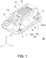
- FIG. 1 is a three-dimensional view of some components of a projection device 100 according to an embodiment of the invention.
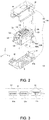
- FIG. 2 is an exploded view of the projection device 100 in FIG. 1 .
- the housing 110 in FIG. 2 may include a first sub-housing 112 and a second sub-housing 114, while the second sub-housing 114 is not shown in FIG. 1 .
- the projection device 100 in the embodiment may include the housing 110 and a display module 120.
- the housing 110 may include an opening 110a.
- the display module 120 is configured in the housing 110 and is configured to project an image through the opening 110a of the housing 110.
- FIG. 3 is a schematic view of an optical engine assembly 124 in FIG. 2 .
- the display module 120 in the embodiment may include the optical engine assembly 124 and at least one first electronic component (for example, two first electronic components 126 and 128 shown).
- the first electronic component 126 is, for example, an image driving circuit board
- the projection device 100 may include a memory 130 configured on the image driving circuit board to store dynamic and/or static image information.
- the other first electronic component 128 is, for example, a power control circuit board.
- the power control circuit board may further include a light source driving circuit board.
- the optical engine assembly 124 may include, for example, a light source 124a, a light valve 124b, and a projection lens 124c.
- the light source 124a is configured to emit an illumination beam L1.
- the light valve 124b is configured to convert the illumination beam L1 into an image beam L2 according to the image information stored in the memory 130.
- the projection lens 124c is configured to project the image beam L2 outside of the projection device 100.
- the image driving circuit board may include an image processor, such as a central processing unit (CPU), a programmable general-purpose or special-purpose microprocessor, a digital signal processor (DSP), a programmable controller, an application specific integrated circuit (ASIC), a programmable logic device (PLD), other similar devices, and various combinations thereof.
- the image driving circuit board may include, for example, a graphics processing unit (GPU).
- the CPU is, for example, an independent processing chip.
- the memory 130 may include, for example, a random access memory (RAM), a read-only memory (ROM), a flash memory, a similar element, or various combinations thereof.
- the light source 124a may include a solid-state illumination source such as a light emitting diode or a laser diode.
- the light valve 124b may include for example a liquid crystal on silicon (LCOS) and a digital micromirror device (DMD).
- the projection lens 124c may include, for example, one or more lenses of various diopters.
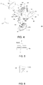
- FIG. 4 is an exploded view of a display module 120 in FIG. 2 .
- the display module 120 in the embodiment further may include a frame 122.
- the frame 122 may include a first assembling portion 122a and at least one second assembling portion 122b (two second assembling portions are shown).
- the optical engine assembly 124 is assembled to the first assembling portion 122a of the frame 122 in a first direction Z.
- the two first electronic components 126 and 128 are assembled to the at least one second assembling portion 122b respectively in a second direction Y and the opposite direction of the second direction Y.
- the second direction Y is different from the first direction Z.
- the two first electronic components 126 and 128 are respectively located on opposite sides of the optical engine assembly 124.
- the first direction Z is, for example, parallel to an optical axis A of the projection lens 124c, and the first direction Z is, for example, perpendicular to the second direction Y.
- the frame 122 of the display module 120 in the embodiment may include the first assembling portion 122a and the at least one second assembling portion 122b.
- the first assembling portion 122a may be used for the optical engine assembly 124 and the second assembling portion 122b may be used for the first electronic components 126 and 128.
- the assembling direction (that is, the second direction Y) of the at least one first electronic component 126, 128 is different from the assembling direction (that is, the first direction Z) of the optical engine assembly 124, so that the display module 120 may not be limited to a single assembling direction and problems of poor space utilization or large volumes caused from excessive components stacked in a single direction may be avoided.
- the optical engine assembly and the frame 122 can be integrated into the display module 120 by using the frame 122, thereby simplifying the manufacturing and maintenance of the projection device 100.
- the display module 120 may further include a second electronic component 129.
- the second electronic component 129 is, for example, a terminal connection board and is configured to be connected with an external power supply.
- the frame 122 may further include a third assembling portion 122c, and the second electronic component 129 may be assembled to the third assembling portion 122c in the first direction Z.
- the optical engine assembly 124 and the second electronic component 129 may be at least partially stacked on each other in the first direction Z.
- the optical engine assembly 124 and the two first electronic components 126, 128 are stacked in the second direction Y.
- the optical engine assembly 124 may include more electronic components of different types, and the frame 122 may correspondingly include more assembling portions, so that the optical engine assembly 124 and the electronic components may be properly assembled to the frame 122 in different directions.
- the optical engine assembly 124, the first electronic components 126 and 128, and the second electronic component 129 in the embodiment are respectively assembled to the first assembling portion 122a, the second assembling portion 122b, and the third assembling portion 122c by using a plurality of screws 121.
- the optical engine assembly 124, the first electronic components 126 and 128, and the second electronic component 129 may be respectively assembled to the first assembling portion 122a, the second assembling portion 122b, and the third assembling portion 122c in other proper manners such as a fastener. This is not limited in the invention.
- the first assembling portion 122a in the embodiment may include a first assembling surface S1 (shown in FIG. 4 ), and the optical engine assembly 124 is assembled on the first assembling surface S1 of the first assembling portion 122a.
- Each second assembling portion 122b may include a second assembling surface S2 (shown in FIG. 4 ), and the first electronic components 126 and 128 are respectively assembled on the second assembling surface S2 of the corresponding second assembling portion 122b.
- the third assembling portion 122c may include a third assembling surface S3 (shown in FIG. 4 ), and the second electronic component 129 is assembled on the third assembling surface S3 of the third assembling portion 122c.
- the third assembling surface S3 of the third assembling portion 122c may be parallel to the first assembling surface S1 of the first assembling portion 122a, and the first assembling surface S1 of the first assembling portion 122a is not parallel to the second assembling surface S2 of the second assembling portion 122b.
- assembling directions (that is, the first direction Z) of the optical engine assembly 124 and the second electronic component 129 may be identical, and the assembling directions of the optical engine assembly 124 and the second electronic component 129 may not be parallel to the assembling direction (that is, the second direction Y) of the first electronic components 126, 128.
- the first assembling surface S1 may be, for example, perpendicular to the second assembling surface S2.
- each second assembling portion 122b may include two extension arms 122b1, and two ends of the first electronic component 126 (or the first electronic component 128) may be respectively assembled on the two extension arms 122b1 of the second assembling portion 122b.
- a portion (for example, an electronic element on the first electronic component) of the first electronic component 126 (or the first electronic component 128) may be located between the two extending arms 122b1.
- the space between the two extension arms 122b1 may be used for accommodating the first electronic component 126 (or the first electronic component 128), so as to further improve the space utilization efficiency in the projection device 100.
- each second assembling portion 122b may include a stopping surface S4 (shown in FIG. 4 ) on each extension arm 122b1, and the stopping surface S4 may be perpendicular to the second assembling surface S2 and may be configured to stop the corresponding first electronic components 126 and 128, so as to prevent the first electronic components 126 and 128 from an unexpected displacement in a third direction X.
- the third direction X may be perpendicular to the first direction Z and the second direction Y.
- the housing 110 in the embodiment may include the first sub-housing 112 and the second sub-housing 114.
- the display module 120 is fixed between the first sub-housing 112 and the second sub-housing 114.
- the display module 120 may be fixed on the first sub-housing 112.
- the image beam L2 generated by the optical engine assembly 124 may be projected through the opening 110a on the first sub-housing 112.
- FIG. 5 is a schematic view of matching a cylinder with a round hole in the embodiment of FIG. 2 .
- FIG. 6 is a schematic view of fitting a hook with a hook fitting portion in the embodiment of FIG. 2 .
- a plurality of round holes O are disposed on the frame 122 of the display module 120, and a plurality of cylinders P are disposed on the first sub-housing 112.
- the display module 120 is located on the first sub-housing 112 by matching the round holes O with the cylinders P.
- a plurality of hooks H1 may be disposed on the second sub-housing 114, and a plurality of hook fitting portions H2 are disposed on the first sub-housing 112.
- the hook fitting portions H2 are configured to be fitted with the hooks H1.
- the second sub-housing 114 may be assembled on the first sub-housing 112 in the first direction Z by clamping the hooks H1 to the hook fitting portions H2, such that the display module 120 is fixed between the first sub-housing 112 and the second sub-housing 114.
- the display module 120 may be positioned onto the first sub-housing 112 by other proper means.
- the first sub-housing 112 and the second sub-housing 114 may be assembled together in other proper manners. This is not limited in the invention.
- the frame of the display module may include a first assembling portion and a second assembling portion.
- the first assembling portion is used for the optical engine assembly and the second assembling portion is used for the first electronic component, so that the assembling direction (that is, the second direction) of the first electronic component is different from the assembling direction (that is, the first direction) of the optical engine assembly. Since the optical engine assembly and electronic components of the display module may be assembled in different directions, problems of poor space utilization or large volumes caused from excessive components stacked in a single direction may be avoided.
- the optical engine assembly and the frame can be integrated into a display module by using the frame, thereby simplifying the manufacturing and maintenance of the projection device.
- the term "the invention”, “the invention” or the like does not necessarily limit the claim scope to a specific embodiment, and the reference to particularly preferred exemplary embodiments of the invention does not imply a limitation on the invention, and no such limitation is to be inferred.
- the invention is limited only by the spirit and scope of the appended claims. Moreover, these claims may refer to use "first”, “second”, etc. following with noun or element. Such terms should be understood as a nomenclature and should not be construed as giving the limitation on the number of the elements modified by such nomenclature unless specific number has been given.
- the abstract of the disclosure is provided to comply with the rules requiring an abstract, which will allow a searcher to quickly ascertain the subject matter of the technical disclosure of any patent issued from this disclosure.
Landscapes
- Physics & Mathematics (AREA)
- General Physics & Mathematics (AREA)
- Transforming Electric Information Into Light Information (AREA)
- Projection Apparatus (AREA)
Abstract
Description
- This application claims the priority of
U.S.Provisional application serial no. 62/853,723, filed on May 29, 2019 201922182138.9, filed on December 9, 2019 - The invention relates to a display device, and in particular, to a projection device including a display device.
- A projection device may be used for projecting a picture outside of the projection device. In the projection device, for example, an illumination beam generated by a light source may be converted into an image beam using a light valve, and then the image beam may be projected through a projection lens, such that an image may be formed.
- As the projection devices are developed in a trend of being miniaturized, a vehicle-used miniaturized projection device is gradually becoming popular. The vehicle-used miniaturized projection device may be installed in a proper position in a car and may be used to project an image or text, for example, text "welcome" or "good trip". The image or text may be projected onto the car door, the ground, or other proper positions when the car door is opened. The vehicle-used miniaturized projection device may also be used for projecting a dynamic image, for example, a video. Since components used for dynamic images, such as an image driving circuit board, may be needed to be configured in the vehicle-used miniaturized projection device, proper configuration of these components in a limited interior space of the projection device is an important topic in the field.
- The information disclosed in this Background section is only for enhancement of understanding of the background of the described technology and therefore it may contain information that does not form the prior art that is already known to persons of ordinary skill in the art. Further, the information disclosed in the Background section does not mean that one or more problems to be resolved by one or more embodiments of the invention were acknowledged by persons of ordinary skill in the art.
- The invention provides a projection device. In the projection device provided, interior space may be effectively utilized and the projection device may have advantages in a smaller volume.
- Other objectives and advantages of the invention may be further understood from the technical features disclosed in the invention.
- The object is solved by the features of the independent claims. Preferred embodiments are given in the dependent claims.
- To achieve one or some or all of the above objectives or other objectives, an embodiment of the invention is to provide a projection device. The projection device may include a housing and a display module. The display module is configured in the housing and may include a frame, an optical engine assembly, and at least one first electronic component. The frame may include a first assembling portion and at least one second assembling portion. The optical engine assembly is assembled to the first assembling portion in a first direction. The at least one first electronic component is assembled to the at least one second assembling portion in a second direction different from the first direction.
- Preferably, the optical engine assembly may comprise a projection lens and the first direction is parallel to an optical axis of the projection lens.
- Preferably, the second direction may be perpendicular to the first direction.
- Preferably, the optical engine assembly and the at least one first electronic component may be stacked in the second direction.
- Preferably, the at least one second assembling portion may include two second assembling portions.
- Preferably, the at least one first electronic component may include two first electronic components.
- Preferably, the two first electronic components may be respectively assembled on the two second assembling portions and may be respectively located on opposite sides of the optical engine assembly.
- Preferably, the two first electronic components may include an image driving circuit board and a power control circuit board.
- Preferably, the first assembling portion may comprise a first assembling surface.
- Preferably, the optical engine assembly may be assembled on the first assembling surface.
- Preferably, the at least one second assembling portion may comprise a second assembling surface.
- Preferably, the at least one first electronic component may be assembled on the second assembling surface.
- Preferably, the first assembling surface may be not parallel to the second assembling surface.
- Preferably, the first assembling surface may be perpendicular to the second assembling surface.
- Preferably, the at least one second assembling portion may comprise a stopping surface.
- Preferably, the stopping surface may be perpendicular to the second assembling surface and may be configured to stop the at least one first electronic component.
- Preferably, the frame may comprise a third assembling portion, the display module may comprise a second electronic component, and the second electronic component may be assembled to the third assembling portion in the first direction.
- Preferably, the second electronic component may be a terminal connection board.
- Preferably, the optical engine assembly and the second electronic component may be at least partially stacked on each other in the first direction.
- Preferably, the housing may comprise a first sub-housing and a second sub-housing.
- Preferably, the display module may be located on the first sub-housing.
- Preferably, an image beam generated by the optical engine assembly may be projected through the first sub-housing.
- Preferably, the second sub-housing may be assembled on the first sub-housing in the first direction, such that the display module is fixed between the first sub-housing and the second sub-housing.
- Preferably, at least one round hole may be disposed on one of the display module and the first sub-housing.
- Preferably, at least one cylinder may be disposed on the other one of the display module and the first sub-housing.
- Preferably, the display module may be located on the first sub-housing by matching the at least one round hole with the at least one cylinder.
- Preferably, at least one hook may be disposed on one of the second sub-housing and the first sub-housing.
- Preferably, at least one hook fitting portion may be disposed on the other one of the second sub-housing and the first sub-housing.
- Preferably, the at least one hook fitting portion may be configured to be fitted with the at least one hook.
- Preferably, the second sub-housing may be assembled on the first sub-housing by fitting the at least one hook with the at least one hook fitting portion.
- Preferably, the at least one second assembling portion may comprise at least two extension arms.
- Preferably, two ends of the at least one first electronic component may be respectively assembled on the at least two extension arms.
- Preferably, a portion of the at least one first electronic component may be located between the at least two extension arms.
- Preferably, the optical engine assembly and the at least one first electronic component may be respectively assembled to the first assembling portion and the at least one second assembling portion by using at least one screw.
- The embodiment of the invention may have at least one of the following advantages or effects. The frame of the display module may include a first assembling portion and a second assembling portion. The first assembling portion is used for the optical engine assembly and the second assembling portion is used for the first electronic component, so that the assembling direction (that is, the second direction) of the first electronic component is different from the assembling direction (that is, the first direction) of the optical engine assembly. Since the display module may not be limited to a single assembling direction, problems of poor space utilization or large volumes caused from excessive components stacked in a single direction may be avoided. In addition, the optical engine assembly and the frame can be integrated into a display module by using the frame, thereby simplifying the manufacturing and maintenance of the projection device.
- Other objectives, features and advantages of the invention will be further understood from the further technological features disclosed by the embodiments of the invention where there are shown and described preferred embodiments of this invention, simply by way of illustration of modes best suited to carry out the invention.
- The accompanying drawings are included to provide a further understanding of the invention, and are incorporated in and constitute a part of this specification. The drawings illustrate embodiments of the invention and, together with the description, serve to explain the principles of the invention.
-
FIG. 1 is a three-dimensional view of some components of a projection device according to an embodiment of the invention. -
FIG. 2 is an exploded view of the projection device in the embodiment ofFIG. 1 . -
FIG. 3 is a schematic view of an optical engine assembly in the embodiment ofFIG. 2 . -
FIG. 4 is an exploded view of a display module in the embodiment ofFIG. 2 . -
FIG. 5 is a schematic view of matching a cylinder with a round hole in the embodiment ofFIG.2 . -
FIG. 6 is a schematic view of fitting a hook with a hook fitting portion in the embodiment ofFIG. 2 . - In the following detailed description of the preferred embodiments, reference is made to the accompanying drawings which form a part hereof, and in which are shown by way of illustration specific embodiments in which the invention may be practiced. In this regard, directional terminology, such as "top," "bottom," "front," "back," etc., is used with reference to the orientation of the Figure(s) being described. The components of the invention can be positioned in a number of different orientations. As such, the directional terminology is used for purposes of illustration and is in no way limiting. On the other hand, the drawings are only schematic and the sizes of components may be exaggerated for clarity. It is to be understood that other embodiments may be utilized and structural changes may be made without departing from the scope of the invention. Also, it is to be understood that the phraseology and terminology used herein are for the purpose of description and should not be regarded as limiting. The use of "including," "comprising," or "having" and variations thereof herein is meant to encompass the items listed thereafter and equivalents thereof as well as additional items. Unless limited otherwise, the terms "connected," "coupled," and "mounted" and variations thereof herein are used broadly and encompass direct and indirect connections, couplings, and mountings. Similarly, the terms "facing," "faces" and variations thereof herein are used broadly and encompass direct and indirect facing, and "adjacent to" and variations thereof herein are used broadly and encompass directly and indirectly "adjacent to". Therefore, the description of "A" component facing "B" component herein may contain the situations that "A" component directly faces "B" component or one or more additional components are between "A" component and "B" component. Also, the description of "A" component "adjacent to" "B" component herein may contain the situations that "A" component is directly "adjacent to" "B" component or one or more additional components are between "A" component and "B" component. Accordingly, the drawings and descriptions will be regarded as illustrative in nature and not as restrictive.
-
FIG. 1 is a three-dimensional view of some components of aprojection device 100 according to an embodiment of the invention.FIG. 2 is an exploded view of theprojection device 100 inFIG. 1 . For the sake of brevity and clarity, thehousing 110 inFIG. 2 may include afirst sub-housing 112 and asecond sub-housing 114, while thesecond sub-housing 114 is not shown inFIG. 1 . Referring toFIG. 1 andFIG. 2 , theprojection device 100 in the embodiment may include thehousing 110 and adisplay module 120. Thehousing 110 may include an opening 110a. Thedisplay module 120 is configured in thehousing 110 and is configured to project an image through the opening 110a of thehousing 110. -
FIG. 3 is a schematic view of anoptical engine assembly 124 inFIG. 2 . Referring toFIG. 2 and FIG. 3 , thedisplay module 120 in the embodiment may include theoptical engine assembly 124 and at least one first electronic component (for example, two firstelectronic components electronic component 126 is, for example, an image driving circuit board, and theprojection device 100 may include amemory 130 configured on the image driving circuit board to store dynamic and/or static image information. The other firstelectronic component 128 is, for example, a power control circuit board. The power control circuit board may further include a light source driving circuit board. Theoptical engine assembly 124 may include, for example, alight source 124a, alight valve 124b, and aprojection lens 124c. Thelight source 124a is configured to emit an illumination beam L1. Thelight valve 124b is configured to convert the illumination beam L1 into an image beam L2 according to the image information stored in thememory 130. Theprojection lens 124c is configured to project the image beam L2 outside of theprojection device 100. - In an embodiment, the image driving circuit board may include an image processor, such as a central processing unit (CPU), a programmable general-purpose or special-purpose microprocessor, a digital signal processor (DSP), a programmable controller, an application specific integrated circuit (ASIC), a programmable logic device (PLD), other similar devices, and various combinations thereof. In other embodiments, the image driving circuit board may include, for example, a graphics processing unit (GPU). The CPU is, for example, an independent processing chip. The
memory 130 may include, for example, a random access memory (RAM), a read-only memory (ROM), a flash memory, a similar element, or various combinations thereof. - In some embodiments, for example, the
light source 124a may include a solid-state illumination source such as a light emitting diode or a laser diode. In some embodiments, thelight valve 124b may include for example a liquid crystal on silicon (LCOS) and a digital micromirror device (DMD). In some embodiments, theprojection lens 124c may include, for example, one or more lenses of various diopters. -
FIG. 4 is an exploded view of adisplay module 120 inFIG. 2 . Referring toFIG. 2 andFIG. 4 , thedisplay module 120 in the embodiment further may include aframe 122. Theframe 122 may include a first assembling portion 122a and at least onesecond assembling portion 122b (two second assembling portions are shown). Theoptical engine assembly 124 is assembled to the first assembling portion 122a of theframe 122 in a first direction Z. In some embodiments, the two firstelectronic components second assembling portion 122b respectively in a second direction Y and the opposite direction of the second direction Y. The second direction Y is different from the first direction Z. In the embodiment, the two firstelectronic components optical engine assembly 124. In the embodiment, the first direction Z is, for example, parallel to an optical axis A of theprojection lens 124c, and the first direction Z is, for example, perpendicular to the second direction Y. - As described above, the
frame 122 of thedisplay module 120 in the embodiment may include the first assembling portion 122a and the at least onesecond assembling portion 122b. The first assembling portion 122a may be used for theoptical engine assembly 124 and thesecond assembling portion 122b may be used for the firstelectronic components electronic component optical engine assembly 124, so that thedisplay module 120 may not be limited to a single assembling direction and problems of poor space utilization or large volumes caused from excessive components stacked in a single direction may be avoided. In addition, the optical engine assembly and theframe 122 can be integrated into thedisplay module 120 by using theframe 122, thereby simplifying the manufacturing and maintenance of theprojection device 100. - Specifically, in the embodiment, the
display module 120 may further include a secondelectronic component 129. The secondelectronic component 129 is, for example, a terminal connection board and is configured to be connected with an external power supply. Correspondingly, theframe 122 may further include athird assembling portion 122c, and the secondelectronic component 129 may be assembled to thethird assembling portion 122c in the first direction Z. In an embodiment, theoptical engine assembly 124 and the secondelectronic component 129 may be at least partially stacked on each other in the first direction Z. Theoptical engine assembly 124 and the two firstelectronic components optical engine assembly 124 may include more electronic components of different types, and theframe 122 may correspondingly include more assembling portions, so that theoptical engine assembly 124 and the electronic components may be properly assembled to theframe 122 in different directions. - Referring to
FIG. 4 , theoptical engine assembly 124, the firstelectronic components electronic component 129 in the embodiment are respectively assembled to the first assembling portion 122a, thesecond assembling portion 122b, and thethird assembling portion 122c by using a plurality ofscrews 121. In other embodiments, theoptical engine assembly 124, the firstelectronic components electronic component 129 may be respectively assembled to the first assembling portion 122a, thesecond assembling portion 122b, and thethird assembling portion 122c in other proper manners such as a fastener. This is not limited in the invention. - More specifically, the first assembling portion 122a in the embodiment may include a first assembling surface S1 (shown in
FIG. 4 ), and theoptical engine assembly 124 is assembled on the first assembling surface S1 of the first assembling portion 122a. Eachsecond assembling portion 122b may include a second assembling surface S2 (shown inFIG. 4 ), and the firstelectronic components portion 122b. Thethird assembling portion 122c may include a third assembling surface S3 (shown inFIG. 4 ), and the secondelectronic component 129 is assembled on the third assembling surface S3 of thethird assembling portion 122c. In an embodiment, the third assembling surface S3 of thethird assembling portion 122c may be parallel to the first assembling surface S1 of the first assembling portion 122a, and the first assembling surface S1 of the first assembling portion 122a is not parallel to the second assembling surface S2 of thesecond assembling portion 122b. In this configuration, assembling directions (that is, the first direction Z) of theoptical engine assembly 124 and the secondelectronic component 129 may be identical, and the assembling directions of theoptical engine assembly 124 and the secondelectronic component 129 may not be parallel to the assembling direction (that is, the second direction Y) of the firstelectronic components - In some embodiments, each
second assembling portion 122b may include two extension arms 122b1, and two ends of the first electronic component 126 (or the first electronic component 128) may be respectively assembled on the two extension arms 122b1 of thesecond assembling portion 122b. A portion (for example, an electronic element on the first electronic component) of the first electronic component 126 (or the first electronic component 128) may be located between the two extending arms 122b1. In other words, the space between the two extension arms 122b1 may be used for accommodating the first electronic component 126 (or the first electronic component 128), so as to further improve the space utilization efficiency in theprojection device 100. - In some embodiments, each
second assembling portion 122b may include a stopping surface S4 (shown inFIG. 4 ) on each extension arm 122b1, and the stopping surface S4 may be perpendicular to the second assembling surface S2 and may be configured to stop the corresponding firstelectronic components electronic components - Referring to
FIG. 2 , thehousing 110 in the embodiment may include thefirst sub-housing 112 and thesecond sub-housing 114. Thedisplay module 120 is fixed between thefirst sub-housing 112 and thesecond sub-housing 114. For example, thedisplay module 120 may be fixed on thefirst sub-housing 112. The image beam L2 generated by theoptical engine assembly 124 may be projected through the opening 110a on thefirst sub-housing 112. -
FIG. 5 is a schematic view of matching a cylinder with a round hole in the embodiment ofFIG. 2 .FIG. 6 is a schematic view of fitting a hook with a hook fitting portion in the embodiment ofFIG. 2 . Referring toFIG. 2 ,FIG. 5, and FIG. 6 , specifically, a plurality of round holes O are disposed on theframe 122 of thedisplay module 120, and a plurality of cylinders P are disposed on thefirst sub-housing 112. Thedisplay module 120 is located on thefirst sub-housing 112 by matching the round holes O with the cylinders P. In some embodiments, a plurality of hooks H1 may be disposed on thesecond sub-housing 114, and a plurality of hook fitting portions H2 are disposed on thefirst sub-housing 112. The hook fitting portions H2 are configured to be fitted with the hooks H1. Specifically, thesecond sub-housing 114 may be assembled on thefirst sub-housing 112 in the first direction Z by clamping the hooks H1 to the hook fitting portions H2, such that thedisplay module 120 is fixed between thefirst sub-housing 112 and thesecond sub-housing 114. In other embodiments, thedisplay module 120 may be positioned onto thefirst sub-housing 112 by other proper means. Thefirst sub-housing 112 and thesecond sub-housing 114 may be assembled together in other proper manners. This is not limited in the invention. - Based on the above, the embodiment of the invention has at least one of the following advantages or effects. The frame of the display module may include a first assembling portion and a second assembling portion. The first assembling portion is used for the optical engine assembly and the second assembling portion is used for the first electronic component, so that the assembling direction (that is, the second direction) of the first electronic component is different from the assembling direction (that is, the first direction) of the optical engine assembly. Since the optical engine assembly and electronic components of the display module may be assembled in different directions, problems of poor space utilization or large volumes caused from excessive components stacked in a single direction may be avoided. In addition, the optical engine assembly and the frame can be integrated into a display module by using the frame, thereby simplifying the manufacturing and maintenance of the projection device.
- The foregoing description of the preferred embodiments of the invention has been presented for purposes of illustration and description. It is not intended to be exhaustive or to limit the invention to the precise form or to exemplary embodiments disclosed. Accordingly, the foregoing description should be regarded as illustrative rather than restrictive. Obviously, many modifications and variations will be apparent to practitioners skilled in this art. The embodiments are chosen and described in order to best explain the principles of the invention and its best mode practical application, thereby to enable persons skilled in the art to understand the invention for various embodiments and with various modifications as are suited to the particular use or implementation contemplated. It is intended that the scope of the invention be defined by the claims appended hereto and their equivalents in which all terms are meant in their broadest reasonable sense unless otherwise indicated. Therefore, the term "the invention", "the invention" or the like does not necessarily limit the claim scope to a specific embodiment, and the reference to particularly preferred exemplary embodiments of the invention does not imply a limitation on the invention, and no such limitation is to be inferred. The invention is limited only by the spirit and scope of the appended claims. Moreover, these claims may refer to use "first", "second", etc. following with noun or element. Such terms should be understood as a nomenclature and should not be construed as giving the limitation on the number of the elements modified by such nomenclature unless specific number has been given. The abstract of the disclosure is provided to comply with the rules requiring an abstract, which will allow a searcher to quickly ascertain the subject matter of the technical disclosure of any patent issued from this disclosure. It is submitted with the understanding that it will not be used to interpret or limit the scope or meaning of the claims. Any advantages and benefits described may not apply to all embodiments of the invention. It should be appreciated that variations may be made in the embodiments described by persons skilled in the art without departing from the scope of the invention as defined by the following claims. Moreover, no element and component in the disclosure is intended to be dedicated to the public regardless of whether the element or component is explicitly recited in the following claims.
Claims (15)
- A projection device, comprising a housing (110) and a display module (120), wherein
the display module (120) is configured in the housing (110) and comprises a frame (122), an optical engine assembly, and at least one first electronic component, wherein
the frame (122) comprises a first assembling portion (122a) and at least one second assembling portion (122b);
the optical engine assembly (124) is assembled to the first assembling portion (122a) in a first direction (Z); and
the at least one first electronic component (126, 128) is assembled to the at least one second assembling portion (122b) in a second direction (Y) different from the first direction (Z). - The projection device according to claim 1, wherein the optical engine assembly (124) comprises a projection lens (124c) and the first direction (Z) is parallel to an optical axis (A) of the projection lens (124c).
- The projection device according to claim 1 or 2, wherein the second direction (Y) is perpendicular to the first direction (Z).
- The projection device according to any one of claims 1, 2 or 3, wherein the optical engine assembly (124) and the at least one first electronic component (126, 128) are stacked in the second direction (Y).
- The projection device according to any one of the preceding claims,, wherein the at least one second assembling portion (122b) may include two second assembling portions, the at least one first electronic component may include two first electronic components, and the two first electronic components are respectively assembled on the two second assembling portions and are respectively located on opposite sides of the optical engine assembly.
- The projection device according to any one of the preceding claims, wherein the two first electronic components (126, 128) may include an image driving circuit board and/or a power control circuit board.
- The projection device according to any one of the preceding claims, wherein the first assembling portion (122a) comprises a first assembling surface (S1), the optical engine assembly (124) is assembled on the first assembling surface (S1), the at least one second assembling portion (122b) comprises a second assembling surface (S2), the at least one first electronic component (126, 128) is assembled on the second assembling surface (S2), and the first assembling surface (S1) is not parallel to the second assembling surface (S2), preferably the first assembling surface (S1) is perpendicular to the second assembling surface (S2) and/or the at least one second assembling portion (122b) comprises a stopping surface (S4), and the stopping surface (S4) is perpendicular to the second assembling surface (S2) and configured to stop the at least one first electronic component (126, 128).
- The projection device according to any one of the preceding claims, wherein the frame (122) comprises a third assembling portion (122c), the display module (120) comprises a second electronic component (129), and the second electronic component (129(is assembled to the third assembling portion (122c) in the first direction (Z).
- The projection device according to claim 8, wherein the second electronic component (129) is a terminal connection board.
- The projection device according to claim 8 or 9, wherein the optical engine assembly (124) and the second electronic component (129) are at least partially stacked on each other in the first direction (Z).
- The projection device according to any one of the preceding claims, wherein the housing (110) comprises a first sub-housing (112) and a second sub-housing (114), the display module (120) is located on the first sub-housing (112), an image beam (L2) generated by the optical engine assembly (124) is projected through the first sub-housing (112), and the second sub-housing (114) is assembled on the first sub-housing (112) in the first direction (Z), such that the display module (120) is fixed between the first sub-housing (112) and the second sub-housing (114).
- The projection device according to claim 11, wherein at least one round hole (O) is disposed on one of the display module (120) and the first sub-housing (112), at least one cylinder (P) is disposed on the other one of the display module (120) and the first sub-housing (112), and the display module (120) is located on the first sub-housing (112) by matching the at least one round hole (O) with the at least one cylinder (P).
- The projection device according to claim 11 or 12, wherein at least one hook (H1) is disposed on one of the second sub-housing (114) and the first sub-housing (112), at least one hook fitting portion (H2) is disposed on the other one of the second sub-housing (114) and the first sub-housing (112), the at least one hook fitting portion (H2) is configured to be fitted with the at least one hook (H1), and the second sub-housing (114) is assembled on the first sub-housing (112) by fitting the at least one hook (H1) with the at least one hook fitting portion (H2).
- The projection device according to any one of the preceding claims, wherein the at least one second assembling portion (122b) comprises at least two extension arms (122b1), two ends of the at least one first electronic component (126, 128) are respectively assembled on the at least two extension arms (122b1), and a portion of the at least one first electronic component (126, 128) is located between the at least two extension arms (122b1).
- The projection device according to any one of the preceding claims, wherein the optical engine assembly (124) and the at least one first electronic component (126, 128) are respectively assembled to the first assembling portion (122a) and the at least one second assembling portion (122b) by using at least one screw (121).
Applications Claiming Priority (2)
| Application Number | Priority Date | Filing Date | Title |
|---|---|---|---|
| US201962853723P | 2019-05-29 | 2019-05-29 | |
| CN201922182138.9U CN210776152U (en) | 2019-05-29 | 2019-12-09 | Projection device |
Publications (2)
| Publication Number | Publication Date |
|---|---|
| EP3745200A1 true EP3745200A1 (en) | 2020-12-02 |
| EP3745200B1 EP3745200B1 (en) | 2024-05-01 |
Family
ID=71036631
Family Applications (1)
| Application Number | Title | Priority Date | Filing Date |
|---|---|---|---|
| EP20176599.7A Active EP3745200B1 (en) | 2019-05-29 | 2020-05-26 | Projection device |
Country Status (3)
| Country | Link |
|---|---|
| US (1) | US11143941B2 (en) |
| EP (1) | EP3745200B1 (en) |
| CN (1) | CN210776152U (en) |
Citations (5)
| Publication number | Priority date | Publication date | Assignee | Title |
|---|---|---|---|---|
| CN1779556A (en) * | 2004-11-24 | 2006-05-31 | 普立尔科技股份有限公司 | Projection device using light emitting diode as light source |
| US20070206124A1 (en) * | 2006-03-03 | 2007-09-06 | Samsung Electronics Co., Ltd. | Projection display apparatus |
| US20110001938A1 (en) * | 2009-07-01 | 2011-01-06 | Wen-Pang Tsai | Optical projection system |
| US8313200B2 (en) * | 2010-02-26 | 2012-11-20 | Coretronic Corporation | Light source apparatus and projection device |
| US9952487B2 (en) * | 2015-05-05 | 2018-04-24 | Qisda Corporation | Projector |
Family Cites Families (7)
| Publication number | Priority date | Publication date | Assignee | Title |
|---|---|---|---|---|
| TWI261495B (en) * | 2005-07-08 | 2006-09-01 | Optoma Corp | Projector with reduced electromagnetic noises |
| JP2008020551A (en) * | 2006-07-11 | 2008-01-31 | Funai Electric Co Ltd | Projector apparatus |
| JP5799539B2 (en) * | 2011-03-23 | 2015-10-28 | セイコーエプソン株式会社 | projector |
| CN204437924U (en) | 2015-04-01 | 2015-07-01 | 岳悫 | Focusing lens and welcome light applied to welcome light |
| JP6585571B2 (en) | 2016-09-21 | 2019-10-02 | 矢崎総業株式会社 | Display device and vehicle door |
| CN210899383U (en) * | 2019-05-29 | 2020-06-30 | 中强光电股份有限公司 | Projection device |
| CN210270495U (en) * | 2019-09-12 | 2020-04-07 | 中强光电股份有限公司 | Projection device |
-
2019
- 2019-12-09 CN CN201922182138.9U patent/CN210776152U/en active Active
-
2020
- 2020-05-25 US US16/882,544 patent/US11143941B2/en active Active
- 2020-05-26 EP EP20176599.7A patent/EP3745200B1/en active Active
Patent Citations (5)
| Publication number | Priority date | Publication date | Assignee | Title |
|---|---|---|---|---|
| CN1779556A (en) * | 2004-11-24 | 2006-05-31 | 普立尔科技股份有限公司 | Projection device using light emitting diode as light source |
| US20070206124A1 (en) * | 2006-03-03 | 2007-09-06 | Samsung Electronics Co., Ltd. | Projection display apparatus |
| US20110001938A1 (en) * | 2009-07-01 | 2011-01-06 | Wen-Pang Tsai | Optical projection system |
| US8313200B2 (en) * | 2010-02-26 | 2012-11-20 | Coretronic Corporation | Light source apparatus and projection device |
| US9952487B2 (en) * | 2015-05-05 | 2018-04-24 | Qisda Corporation | Projector |
Also Published As
| Publication number | Publication date |
|---|---|
| CN210776152U (en) | 2020-06-16 |
| EP3745200B1 (en) | 2024-05-01 |
| US11143941B2 (en) | 2021-10-12 |
| US20200379326A1 (en) | 2020-12-03 |
Similar Documents
| Publication | Publication Date | Title |
|---|---|---|
| CN1882236B (en) | Displays with indirect lighting structures | |
| US10620521B2 (en) | Adjustment mechanism and projection device | |
| US11340517B2 (en) | Projection lens module and projector | |
| US20220082918A1 (en) | Light source module and projection device | |
| US12235570B2 (en) | Projection apparatus having speaker | |
| US7798651B2 (en) | Fixing mechanism for fixing a light valve and a thermal module of an optical engine and related optical engine | |
| US11143941B2 (en) | Projection device | |
| US20240142864A1 (en) | Projection device | |
| US11640105B2 (en) | Projector and light source module thereof | |
| US10890832B2 (en) | Optical device and optical module | |
| US10831091B2 (en) | Projection device and illumination system | |
| US20200159095A1 (en) | Projection device | |
| EP1668916A1 (en) | Projection apparatus with axis parallel micro mirrors and light sources | |
| US11150545B2 (en) | Projection apparatus with U-shaped printed circuit board | |
| US11143940B2 (en) | Optical module and projector | |
| US20250076745A1 (en) | Optical engine module and projector | |
| CN110035158A (en) | Terminal device | |
| US20110279783A1 (en) | Optical engine for projector | |
| US7914156B2 (en) | Optical engine for a projection display device | |
| JP3607281B2 (en) | Mobile terminal device | |
| US20210333695A1 (en) | Optical module and projection device | |
| US12405520B2 (en) | Light source fixing assembly and projection device | |
| US20210018827A1 (en) | Light source module and projection device | |
| US20110001938A1 (en) | Optical projection system | |
| US20140111778A1 (en) | Projector |
Legal Events
| Date | Code | Title | Description |
|---|---|---|---|
| PUAI | Public reference made under article 153(3) epc to a published international application that has entered the european phase |
Free format text: ORIGINAL CODE: 0009012 |
|
| STAA | Information on the status of an ep patent application or granted ep patent |
Free format text: STATUS: REQUEST FOR EXAMINATION WAS MADE |
|
| 17P | Request for examination filed |
Effective date: 20200526 |
|
| AK | Designated contracting states |
Kind code of ref document: A1 Designated state(s): AL AT BE BG CH CY CZ DE DK EE ES FI FR GB GR HR HU IE IS IT LI LT LU LV MC MK MT NL NO PL PT RO RS SE SI SK SM TR |
|
| AX | Request for extension of the european patent |
Extension state: BA ME |
|
| RBV | Designated contracting states (corrected) |
Designated state(s): AL AT BE BG CH CY CZ DE DK EE ES FI FR GB GR HR HU IE IS IT LI LT LU LV MC MK MT NL NO PL PT RO RS SE SI SK SM TR |
|
| GRAP | Despatch of communication of intention to grant a patent |
Free format text: ORIGINAL CODE: EPIDOSNIGR1 |
|
| STAA | Information on the status of an ep patent application or granted ep patent |
Free format text: STATUS: GRANT OF PATENT IS INTENDED |
|
| INTG | Intention to grant announced |
Effective date: 20231219 |
|
| GRAS | Grant fee paid |
Free format text: ORIGINAL CODE: EPIDOSNIGR3 |
|
| GRAA | (expected) grant |
Free format text: ORIGINAL CODE: 0009210 |
|
| STAA | Information on the status of an ep patent application or granted ep patent |
Free format text: STATUS: THE PATENT HAS BEEN GRANTED |
|
| AK | Designated contracting states |
Kind code of ref document: B1 Designated state(s): AL AT BE BG CH CY CZ DE DK EE ES FI FR GB GR HR HU IE IS IT LI LT LU LV MC MK MT NL NO PL PT RO RS SE SI SK SM TR |
|
| REG | Reference to a national code |
Ref country code: GB Ref legal event code: FG4D |
|
| REG | Reference to a national code |
Ref country code: CH Ref legal event code: EP |
|
| REG | Reference to a national code |
Ref country code: IE Ref legal event code: FG4D |
|
| REG | Reference to a national code |
Ref country code: DE Ref legal event code: R096 Ref document number: 602020029939 Country of ref document: DE |
|
| REG | Reference to a national code |
Ref country code: LT Ref legal event code: MG9D |
|
| REG | Reference to a national code |
Ref country code: NL Ref legal event code: MP Effective date: 20240501 |
|
| PG25 | Lapsed in a contracting state [announced via postgrant information from national office to epo] |
Ref country code: IS Free format text: LAPSE BECAUSE OF FAILURE TO SUBMIT A TRANSLATION OF THE DESCRIPTION OR TO PAY THE FEE WITHIN THE PRESCRIBED TIME-LIMIT Effective date: 20240901 |
|
| PG25 | Lapsed in a contracting state [announced via postgrant information from national office to epo] |
Ref country code: BG Free format text: LAPSE BECAUSE OF FAILURE TO SUBMIT A TRANSLATION OF THE DESCRIPTION OR TO PAY THE FEE WITHIN THE PRESCRIBED TIME-LIMIT Effective date: 20240501 |
|
| PG25 | Lapsed in a contracting state [announced via postgrant information from national office to epo] |
Ref country code: HR Free format text: LAPSE BECAUSE OF FAILURE TO SUBMIT A TRANSLATION OF THE DESCRIPTION OR TO PAY THE FEE WITHIN THE PRESCRIBED TIME-LIMIT Effective date: 20240501 Ref country code: FI Free format text: LAPSE BECAUSE OF FAILURE TO SUBMIT A TRANSLATION OF THE DESCRIPTION OR TO PAY THE FEE WITHIN THE PRESCRIBED TIME-LIMIT Effective date: 20240501 |
|
| PG25 | Lapsed in a contracting state [announced via postgrant information from national office to epo] |
Ref country code: GR Free format text: LAPSE BECAUSE OF FAILURE TO SUBMIT A TRANSLATION OF THE DESCRIPTION OR TO PAY THE FEE WITHIN THE PRESCRIBED TIME-LIMIT Effective date: 20240802 |
|
| PG25 | Lapsed in a contracting state [announced via postgrant information from national office to epo] |
Ref country code: PT Free format text: LAPSE BECAUSE OF FAILURE TO SUBMIT A TRANSLATION OF THE DESCRIPTION OR TO PAY THE FEE WITHIN THE PRESCRIBED TIME-LIMIT Effective date: 20240902 |
|
| REG | Reference to a national code |
Ref country code: AT Ref legal event code: MK05 Ref document number: 1683185 Country of ref document: AT Kind code of ref document: T Effective date: 20240501 |
|
| PG25 | Lapsed in a contracting state [announced via postgrant information from national office to epo] |
Ref country code: NL Free format text: LAPSE BECAUSE OF FAILURE TO SUBMIT A TRANSLATION OF THE DESCRIPTION OR TO PAY THE FEE WITHIN THE PRESCRIBED TIME-LIMIT Effective date: 20240501 |
|
| PG25 | Lapsed in a contracting state [announced via postgrant information from national office to epo] |
Ref country code: ES Free format text: LAPSE BECAUSE OF FAILURE TO SUBMIT A TRANSLATION OF THE DESCRIPTION OR TO PAY THE FEE WITHIN THE PRESCRIBED TIME-LIMIT Effective date: 20240501 |
|
| PG25 | Lapsed in a contracting state [announced via postgrant information from national office to epo] |
Ref country code: AT Free format text: LAPSE BECAUSE OF FAILURE TO SUBMIT A TRANSLATION OF THE DESCRIPTION OR TO PAY THE FEE WITHIN THE PRESCRIBED TIME-LIMIT Effective date: 20240501 |
|
| PG25 | Lapsed in a contracting state [announced via postgrant information from national office to epo] |
Ref country code: PL Free format text: LAPSE BECAUSE OF FAILURE TO SUBMIT A TRANSLATION OF THE DESCRIPTION OR TO PAY THE FEE WITHIN THE PRESCRIBED TIME-LIMIT Effective date: 20240501 |
|
| PG25 | Lapsed in a contracting state [announced via postgrant information from national office to epo] |
Ref country code: LV Free format text: LAPSE BECAUSE OF FAILURE TO SUBMIT A TRANSLATION OF THE DESCRIPTION OR TO PAY THE FEE WITHIN THE PRESCRIBED TIME-LIMIT Effective date: 20240501 |
|
| PG25 | Lapsed in a contracting state [announced via postgrant information from national office to epo] |
Ref country code: PT Free format text: LAPSE BECAUSE OF FAILURE TO SUBMIT A TRANSLATION OF THE DESCRIPTION OR TO PAY THE FEE WITHIN THE PRESCRIBED TIME-LIMIT Effective date: 20240902 Ref country code: PL Free format text: LAPSE BECAUSE OF FAILURE TO SUBMIT A TRANSLATION OF THE DESCRIPTION OR TO PAY THE FEE WITHIN THE PRESCRIBED TIME-LIMIT Effective date: 20240501 Ref country code: NO Free format text: LAPSE BECAUSE OF FAILURE TO SUBMIT A TRANSLATION OF THE DESCRIPTION OR TO PAY THE FEE WITHIN THE PRESCRIBED TIME-LIMIT Effective date: 20240801 Ref country code: NL Free format text: LAPSE BECAUSE OF FAILURE TO SUBMIT A TRANSLATION OF THE DESCRIPTION OR TO PAY THE FEE WITHIN THE PRESCRIBED TIME-LIMIT Effective date: 20240501 Ref country code: LV Free format text: LAPSE BECAUSE OF FAILURE TO SUBMIT A TRANSLATION OF THE DESCRIPTION OR TO PAY THE FEE WITHIN THE PRESCRIBED TIME-LIMIT Effective date: 20240501 Ref country code: IS Free format text: LAPSE BECAUSE OF FAILURE TO SUBMIT A TRANSLATION OF THE DESCRIPTION OR TO PAY THE FEE WITHIN THE PRESCRIBED TIME-LIMIT Effective date: 20240901 Ref country code: HR Free format text: LAPSE BECAUSE OF FAILURE TO SUBMIT A TRANSLATION OF THE DESCRIPTION OR TO PAY THE FEE WITHIN THE PRESCRIBED TIME-LIMIT Effective date: 20240501 Ref country code: GR Free format text: LAPSE BECAUSE OF FAILURE TO SUBMIT A TRANSLATION OF THE DESCRIPTION OR TO PAY THE FEE WITHIN THE PRESCRIBED TIME-LIMIT Effective date: 20240802 Ref country code: FI Free format text: LAPSE BECAUSE OF FAILURE TO SUBMIT A TRANSLATION OF THE DESCRIPTION OR TO PAY THE FEE WITHIN THE PRESCRIBED TIME-LIMIT Effective date: 20240501 Ref country code: ES Free format text: LAPSE BECAUSE OF FAILURE TO SUBMIT A TRANSLATION OF THE DESCRIPTION OR TO PAY THE FEE WITHIN THE PRESCRIBED TIME-LIMIT Effective date: 20240501 Ref country code: BG Free format text: LAPSE BECAUSE OF FAILURE TO SUBMIT A TRANSLATION OF THE DESCRIPTION OR TO PAY THE FEE WITHIN THE PRESCRIBED TIME-LIMIT Effective date: 20240501 Ref country code: AT Free format text: LAPSE BECAUSE OF FAILURE TO SUBMIT A TRANSLATION OF THE DESCRIPTION OR TO PAY THE FEE WITHIN THE PRESCRIBED TIME-LIMIT Effective date: 20240501 Ref country code: RS Free format text: LAPSE BECAUSE OF FAILURE TO SUBMIT A TRANSLATION OF THE DESCRIPTION OR TO PAY THE FEE WITHIN THE PRESCRIBED TIME-LIMIT Effective date: 20240801 |
|
| REG | Reference to a national code |
Ref country code: CH Ref legal event code: PL |
|
| PG25 | Lapsed in a contracting state [announced via postgrant information from national office to epo] |
Ref country code: DK Free format text: LAPSE BECAUSE OF FAILURE TO SUBMIT A TRANSLATION OF THE DESCRIPTION OR TO PAY THE FEE WITHIN THE PRESCRIBED TIME-LIMIT Effective date: 20240501 |
|
| PG25 | Lapsed in a contracting state [announced via postgrant information from national office to epo] |
Ref country code: LU Free format text: LAPSE BECAUSE OF NON-PAYMENT OF DUE FEES Effective date: 20240526 |
|
| PG25 | Lapsed in a contracting state [announced via postgrant information from national office to epo] |
Ref country code: EE Free format text: LAPSE BECAUSE OF FAILURE TO SUBMIT A TRANSLATION OF THE DESCRIPTION OR TO PAY THE FEE WITHIN THE PRESCRIBED TIME-LIMIT Effective date: 20240501 |
|
| PG25 | Lapsed in a contracting state [announced via postgrant information from national office to epo] |
Ref country code: CZ Free format text: LAPSE BECAUSE OF FAILURE TO SUBMIT A TRANSLATION OF THE DESCRIPTION OR TO PAY THE FEE WITHIN THE PRESCRIBED TIME-LIMIT Effective date: 20240501 |
|
| PG25 | Lapsed in a contracting state [announced via postgrant information from national office to epo] |
Ref country code: SK Free format text: LAPSE BECAUSE OF FAILURE TO SUBMIT A TRANSLATION OF THE DESCRIPTION OR TO PAY THE FEE WITHIN THE PRESCRIBED TIME-LIMIT Effective date: 20240501 Ref country code: RO Free format text: LAPSE BECAUSE OF FAILURE TO SUBMIT A TRANSLATION OF THE DESCRIPTION OR TO PAY THE FEE WITHIN THE PRESCRIBED TIME-LIMIT Effective date: 20240501 |
|
| PG25 | Lapsed in a contracting state [announced via postgrant information from national office to epo] |
Ref country code: SM Free format text: LAPSE BECAUSE OF FAILURE TO SUBMIT A TRANSLATION OF THE DESCRIPTION OR TO PAY THE FEE WITHIN THE PRESCRIBED TIME-LIMIT Effective date: 20240501 |
|
| PG25 | Lapsed in a contracting state [announced via postgrant information from national office to epo] |
Ref country code: SM Free format text: LAPSE BECAUSE OF FAILURE TO SUBMIT A TRANSLATION OF THE DESCRIPTION OR TO PAY THE FEE WITHIN THE PRESCRIBED TIME-LIMIT Effective date: 20240501 Ref country code: SK Free format text: LAPSE BECAUSE OF FAILURE TO SUBMIT A TRANSLATION OF THE DESCRIPTION OR TO PAY THE FEE WITHIN THE PRESCRIBED TIME-LIMIT Effective date: 20240501 Ref country code: RO Free format text: LAPSE BECAUSE OF FAILURE TO SUBMIT A TRANSLATION OF THE DESCRIPTION OR TO PAY THE FEE WITHIN THE PRESCRIBED TIME-LIMIT Effective date: 20240501 Ref country code: LU Free format text: LAPSE BECAUSE OF NON-PAYMENT OF DUE FEES Effective date: 20240526 Ref country code: EE Free format text: LAPSE BECAUSE OF FAILURE TO SUBMIT A TRANSLATION OF THE DESCRIPTION OR TO PAY THE FEE WITHIN THE PRESCRIBED TIME-LIMIT Effective date: 20240501 Ref country code: DK Free format text: LAPSE BECAUSE OF FAILURE TO SUBMIT A TRANSLATION OF THE DESCRIPTION OR TO PAY THE FEE WITHIN THE PRESCRIBED TIME-LIMIT Effective date: 20240501 Ref country code: CZ Free format text: LAPSE BECAUSE OF FAILURE TO SUBMIT A TRANSLATION OF THE DESCRIPTION OR TO PAY THE FEE WITHIN THE PRESCRIBED TIME-LIMIT Effective date: 20240501 Ref country code: CH Free format text: LAPSE BECAUSE OF NON-PAYMENT OF DUE FEES Effective date: 20240531 Ref country code: MC Free format text: LAPSE BECAUSE OF FAILURE TO SUBMIT A TRANSLATION OF THE DESCRIPTION OR TO PAY THE FEE WITHIN THE PRESCRIBED TIME-LIMIT Effective date: 20240501 |
|
| REG | Reference to a national code |
Ref country code: DE Ref legal event code: R097 Ref document number: 602020029939 Country of ref document: DE |
|
| PG25 | Lapsed in a contracting state [announced via postgrant information from national office to epo] |
Ref country code: IT Free format text: LAPSE BECAUSE OF FAILURE TO SUBMIT A TRANSLATION OF THE DESCRIPTION OR TO PAY THE FEE WITHIN THE PRESCRIBED TIME-LIMIT Effective date: 20240501 |
|
| REG | Reference to a national code |
Ref country code: BE Ref legal event code: MM Effective date: 20240531 |
|
| PLBE | No opposition filed within time limit |
Free format text: ORIGINAL CODE: 0009261 |
|
| STAA | Information on the status of an ep patent application or granted ep patent |
Free format text: STATUS: NO OPPOSITION FILED WITHIN TIME LIMIT |
|
| 26N | No opposition filed |
Effective date: 20250204 |
|
| PG25 | Lapsed in a contracting state [announced via postgrant information from national office to epo] |
Ref country code: IE Free format text: LAPSE BECAUSE OF NON-PAYMENT OF DUE FEES Effective date: 20240526 |
|
| PG25 | Lapsed in a contracting state [announced via postgrant information from national office to epo] |
Ref country code: SI Free format text: LAPSE BECAUSE OF FAILURE TO SUBMIT A TRANSLATION OF THE DESCRIPTION OR TO PAY THE FEE WITHIN THE PRESCRIBED TIME-LIMIT Effective date: 20240501 Ref country code: BE Free format text: LAPSE BECAUSE OF NON-PAYMENT OF DUE FEES Effective date: 20240531 |
|
| PG25 | Lapsed in a contracting state [announced via postgrant information from national office to epo] |
Ref country code: HU Free format text: LAPSE BECAUSE OF FAILURE TO SUBMIT A TRANSLATION OF THE DESCRIPTION OR TO PAY THE FEE WITHIN THE PRESCRIBED TIME-LIMIT; INVALID AB INITIO Effective date: 20200526 |
|
| PG25 | Lapsed in a contracting state [announced via postgrant information from national office to epo] |
Ref country code: SE Free format text: LAPSE BECAUSE OF FAILURE TO SUBMIT A TRANSLATION OF THE DESCRIPTION OR TO PAY THE FEE WITHIN THE PRESCRIBED TIME-LIMIT Effective date: 20240501 |
|
| PG25 | Lapsed in a contracting state [announced via postgrant information from national office to epo] |
Ref country code: CY Free format text: LAPSE BECAUSE OF FAILURE TO SUBMIT A TRANSLATION OF THE DESCRIPTION OR TO PAY THE FEE WITHIN THE PRESCRIBED TIME-LIMIT; INVALID AB INITIO Effective date: 20200526 |
|
| PG25 | Lapsed in a contracting state [announced via postgrant information from national office to epo] |
Ref country code: TR Free format text: LAPSE BECAUSE OF FAILURE TO SUBMIT A TRANSLATION OF THE DESCRIPTION OR TO PAY THE FEE WITHIN THE PRESCRIBED TIME-LIMIT Effective date: 20240501 |
|
| PG25 | Lapsed in a contracting state [announced via postgrant information from national office to epo] |
Ref country code: LT Free format text: LAPSE BECAUSE OF FAILURE TO SUBMIT A TRANSLATION OF THE DESCRIPTION OR TO PAY THE FEE WITHIN THE PRESCRIBED TIME-LIMIT Effective date: 20240501 |
|
| PGFP | Annual fee paid to national office [announced via postgrant information from national office to epo] |
Ref country code: GB Payment date: 20260521 Year of fee payment: 7 |
|
| PGFP | Annual fee paid to national office [announced via postgrant information from national office to epo] |
Ref country code: DE Payment date: 20260527 Year of fee payment: 7 |
|
| PGFP | Annual fee paid to national office [announced via postgrant information from national office to epo] |
Ref country code: FR Payment date: 20260522 Year of fee payment: 7 |