EP3745182A1 - Controllably deformable mirror device - Google Patents
Controllably deformable mirror device Download PDFInfo
- Publication number
- EP3745182A1 EP3745182A1 EP19177051.0A EP19177051A EP3745182A1 EP 3745182 A1 EP3745182 A1 EP 3745182A1 EP 19177051 A EP19177051 A EP 19177051A EP 3745182 A1 EP3745182 A1 EP 3745182A1
- Authority
- EP
- European Patent Office
- Prior art keywords
- protrusions
- flexible layer
- layer
- mirror
- back surface
- Prior art date
- Legal status (The legal status is an assumption and is not a legal conclusion. Google has not performed a legal analysis and makes no representation as to the accuracy of the status listed.)
- Withdrawn
Links
- 239000000463 material Substances 0.000 claims abstract description 31
- 238000004519 manufacturing process Methods 0.000 claims description 6
- 238000000034 method Methods 0.000 claims description 4
- 230000008878 coupling Effects 0.000 claims 1
- 238000010168 coupling process Methods 0.000 claims 1
- 238000005859 coupling reaction Methods 0.000 claims 1
- 239000000853 adhesive Substances 0.000 description 10
- 230000001070 adhesive effect Effects 0.000 description 10
- 230000000694 effects Effects 0.000 description 9
- 230000003287 optical effect Effects 0.000 description 8
- 229910052751 metal Inorganic materials 0.000 description 7
- 239000002184 metal Substances 0.000 description 7
- 239000000203 mixture Substances 0.000 description 4
- 230000007423 decrease Effects 0.000 description 3
- 239000011521 glass Substances 0.000 description 3
- 230000008021 deposition Effects 0.000 description 2
- 229910002065 alloy metal Inorganic materials 0.000 description 1
- 239000011248 coating agent Substances 0.000 description 1
- 238000000576 coating method Methods 0.000 description 1
- 230000001419 dependent effect Effects 0.000 description 1
- 238000009713 electroplating Methods 0.000 description 1
- 230000005686 electrostatic field Effects 0.000 description 1
- 229920006333 epoxy cement Polymers 0.000 description 1
- 238000010438 heat treatment Methods 0.000 description 1
- 238000003701 mechanical milling Methods 0.000 description 1
- 238000003801 milling Methods 0.000 description 1
- 210000001747 pupil Anatomy 0.000 description 1
Images

Classifications
-
- G—PHYSICS
- G02—OPTICS
- G02B—OPTICAL ELEMENTS, SYSTEMS OR APPARATUS
- G02B26/00—Optical devices or arrangements for the control of light using movable or deformable optical elements
- G02B26/08—Optical devices or arrangements for the control of light using movable or deformable optical elements for controlling the direction of light
- G02B26/0816—Optical devices or arrangements for the control of light using movable or deformable optical elements for controlling the direction of light by means of one or more reflecting elements
- G02B26/0825—Optical devices or arrangements for the control of light using movable or deformable optical elements for controlling the direction of light by means of one or more reflecting elements the reflecting element being a flexible sheet or membrane, e.g. for varying the focus
-
- G—PHYSICS
- G02—OPTICS
- G02B—OPTICAL ELEMENTS, SYSTEMS OR APPARATUS
- G02B26/00—Optical devices or arrangements for the control of light using movable or deformable optical elements
- G02B26/08—Optical devices or arrangements for the control of light using movable or deformable optical elements for controlling the direction of light
- G02B26/0816—Optical devices or arrangements for the control of light using movable or deformable optical elements for controlling the direction of light by means of one or more reflecting elements
- G02B26/0833—Optical devices or arrangements for the control of light using movable or deformable optical elements for controlling the direction of light by means of one or more reflecting elements the reflecting element being a micromechanical device, e.g. a MEMS mirror, DMD
- G02B26/085—Optical devices or arrangements for the control of light using movable or deformable optical elements for controlling the direction of light by means of one or more reflecting elements the reflecting element being a micromechanical device, e.g. a MEMS mirror, DMD the reflecting means being moved or deformed by electromagnetic means
Definitions
- the invention relates to a mirror device with a controllably deformable mirror and an optical system comprising such a device.
- Controllably deformable mirrors are known for use to adjust the phase patterns of wave fronts, for example to compensate for the effect of turbulence along the optical path.
- WO2011129694 and the references cited therein describe controllably deformable mirrors.
- the controllably deformable mirror comprises a flexible mirror surface and a large number of actuators to push and pull the mirror surface forward or backward at an array of points at the back of the mirror surface.
- an actuator is used that has a base part on a support and a moving part attached to the point on an actuated layer, which may be the flexible mirror itself or an intermediate flexible layer to which the flexible mirror is attached.
- the moving parts are moved by forces excited from the base parts, for example using electric current through coils in the base part to create magnetic fields that act on magnets in the moving parts.
- the moving part may be bonded to the actuated layer by means of adhesive, epoxy cement or a frit bond.
- Electrostatic or magnetic clamping between the moving parts and the actuated layer may be used to couple the moving parts to the actuated layer.
- US5719846 discloses use of electrostatic clamping.
- the actual deformations of the mirror depend on the shape of the moving parts.
- the regions in the mirror behind which the moving parts are attached are less flexible than regions between the attachments of the moving parts.
- it creates temperature dependent strain that deforms the mirror surface. Both can create local deformation of the mirror with much higher spatial frequency components than can be compensated by controlled deformation. This negatively affects the quality of the adjustment of the phase patterns of wave fronts.
- a deformable mirror device comprising
- protrusions that consist entirely of the same material as the flexible layer extend from the back surface means that no adhesive of a different material is present between the protrusions and the flexible layer. As a result no local distortion of the flexible layer will arise due to such adhesive under influence of temperature variations. Of course, temperature variations can affect the length of the protrusions, and thus produce the normal deformations like those produced by means of movement of the actuators, but local distortions, i.e. distortions that deviate from these normal deformations, are avoided.
- the protrusions extend from the back surface, that is from the plane of the back surface when the flexible layer is planar. The actuators are connected only at the distal end surface of the protrusions.
- Adhesive may be used on the distal ends of the protrusions to connect the protrusions to the actuators, but because such adhesive is at a distance from the flexible layer it has no local distortion effect, or at most a small local distortion effect, on the flexible layer. Such distortion effects, if any, decrease with the length of the protrusions.
- the length of the protrusions is at least as large as half their diameter.
- the flexible layer and the protrusions are part of an integral body of the first material.
- an integral body can be manufactured for example by starting from a larger body of the first material that has a thickness that is at least a sum of the thickness of the flexible layer and the length of the protrusions, and selectively removing the part of the larger body between the protrusions to create the back surface of the flexible layer between the protrusions.
- Another method of manufacturing may comprise anodic bonding of the protrusions to the flexible layer.
- each protrusion at least partly has a convex surface that at least partly has a spherical shape
- the distal ends of moving parts of the actuators have part-spherical concave surfaces with the same radius of curvature as the distal end of the protrusions.
- the center of curvature of the spherical concave surface or surface part lies on or between the front and back surface of the flexible layer (i.e. the interpolation of the back surface outside the protrusions), and more preferably midway between the front and back surface of the flexible layer. This further reduces the distortion effect of misalignment.
- a method of manufacturing a deformable mirror device is provided.
- the deformable mirror surface is present on a front surface of a flexible layer.
- the method comprises manufacturing the flexible layer from a body of a first material by selectively removing the first material from said body to form a back surface of the flexible layer, the selective removing leaving protrusions extending from a back surface of the flexible layer, or attaching the protrusions of the first material to the back surface by anodic bonding.
- the actuators are coupled to the protrusions
- Figure 1 shows an example of an optical system wherein a mirror device 14 with a controllably deformable mirror is used.
- the system comprises a telescope 12, mirror device 14 and a detector 16.
- the optical path 10 runs from telescope 12 to mirror device 14, which reflects optical path 10 to detector 16.
- mirror device 14 is located at a pupil plane of telescope 12.
- Detector 16 may comprise optical elements (not shown) to focus the light from optical path 10 on a sensor (not shown) such as an image sensor or a spot sensor.
- FIG. 2a shows a cross-section of part of a first embodiment of mirror device 14.
- Mirror device comprises a flexible mirror surface 20 and actuators 22 on a base 23.
- the figure shows only part of mirror surface 20 and base 23 with a few actuators, but it should be noted that mirror device 14 may comprise many more actuators, preferably in a two-dimensional array e.g. with rows and columns of at least ten actuators.
- the non-actuated shape of mirror surface 20 may be flat, or it may be curved to form a reflector lens, the surface of which can be adapted locally using actuators 22.
- flexible mirror surface 20 is the front surface of an integral body 24 that is made of a single homogeneous material, e.g. of a metal.
- integral body 24 may be made of metal or glass material with a reflective layer on top, which forms flexible mirror surface 20.
- Adjacent flexible mirror surface 20 Adjacent flexible mirror surface 20, a part of integral body 24 forms a front layer that extends over the entire front surface of integral body 24, forming or supporting flexible mirror surface 20. This part of integral body 24 is so thin that it can be deformed under influence of forces exerted on protrusions 26.
- the front layer of integral body 24 may be 1-5 mm thick for example, and the surface may extend over 100 millimeter or more.
- Integral body 24 has a plurality of elongated protrusions 26 at the back surface of integral body 24 (herein the back surface of integral body 24 is the part of integral body 24 between protrusions 26 and the interpolation of that part trough protrusions).
- Elongated protrusions 26 extend in a direction away from the back surface of the front layer (along the z direction as indicated).
- the front layer and protrusions 26 have the same material composition, and form an integral body.
- the size of the protrusions is designed to create a significant reduction on the effect on deformation of the flexible mirror surface 20 of adhesive on the distal end of protrusions 26 (i.e. a reduction of the effect by at least a factor of five or ten).
- protrusions 26 may extend for between one to five millimeter from the back surface.
- the distal end of protrusion 26 has a convex curved shape or partly has a convex curved shape that includes the point of protrusion 26 at its greatest distance from the back surface of integral body 24, and the greatest distance is least half the radius of curvature of the convex curved part.
- Protrusions 26 may have any shape in cross section, for example circular, elliptical or rectangular. In a preferred embodiment a circular cross-section is used.
- the diameter of protrusions 26, i.e. the maximum distance between any pair of points on the circumference of the cross-section is preferably less than or equal to twice its length.
- the diameter may be four millimeter.
- the distance between the outsides of neighboring protrusions 26 is preferably larger than their diameter, and more preferably more than twice their diameter.
- the center to center distance may be twenty millimeter, or at least more than eight millimeter when the protrusions have a diameter of 4 millimeter.
- no significant amount of material other than that of integral body 24 is present on the front surface and back surface of integral body 24.
- a coating of not more than say ten micrometers is not regarded as a significant amount.
- Adhesive of a different material composition than that of integral body 24 may be present on the distal ends of protrusions 26. Due to the different composition, the adhesive creates stress, for example when it is cured and/or as a result of temperature variation. The magnitude of this stress decreases with distance from the adhesive along protrusions 26, thereby reducing its effect on the flexible mirror surface.
- Respective ones of actuators 22 are attached to respective ones of protrusions 26, at the distal end, or at least a distance from the front layer of integral body 24.
- the amount of stress created by the attachment of the actuators decreases with distance between the attachment and the layer of integral body 24 that extends over the entire front surface of integral body 24.
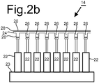
- Figure 2b shows a cross-section of part of a second embodiment of mirror device 14 with a reflective mirror layer 28 is provided on integral body 24.
- flexible mirror surface 20 is the front surface of reflective mirror layer 28 and the back surface of reflective mirror layer 28 is in spatially continuous contact with integral body 24 over the whole back surface of reflective mirror layer 28.
- one or more further layers may be present between reflective mirror layer 28 and integral body 24 in spatially continuous contact with each other behind the whole back surface of reflective mirror layer 28.
- the combination of reflective mirror layer 28, and the part of integral body 24 that extends over the entire mirror surface and optionally the further layers is so thin that these can be deformed under influence of forces exerted on protrusions 26.
- Integral body 24 may be manufactured for example from a plate of the single homogeneous material, by milling to remove the material between protrusions 26. Mechanical milling may be used, or the material between protrusions 26 may be removed partly or wholly chemically or electrochemically. In other embodiments the protrusions may be grown by spatially selective deposition.
- the front surface of integral body 24 may be processed after the creation of protrusions 26 to form flexible mirror surface 20, or to create a thin and smooth surface to which reflective mirror layer 28 can spatially continuously be attached by material deposition or by attaching a pre-formed reflective mirror layer.
- protrusions from integral body 24 has the effect that the movement of reflective mirror layer 28 due to actuation is not affected by temperature fluctuations. Inherent mechanical stress in integral body 24 can be avoided, so that this does not affect reflective mirror layer 28.
- the use of protrusions from integral body 24 also makes it easier to process the front surface of integral body 24 at any time, compared to manufacturing methods wherein actuators are bonded directly to the part of integral body 24 that extends along the whole mirror surface 20.
- Integral body 24 may consist of a metal or glass for example.
- the metal may be an alloy metal or a pure metal.
- the front surface of the metal itself can be used as mirror surface or a mirror layer may be deposited on the front surface.
- a mirror layer is preferably deposited on the front surface, for example by electroplating. In other embodiments a detachable mirror layer may be used.
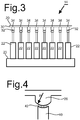
- Figure 3 shows a cross section of part of a further embodiment of the mirror device.
- the integral body has been created by bonding a flexible layer 30 with parallel front and back surfaces and protrusions 32 of the same material as layer 30.
- Protrusions 32 are bonded to layer 30 using anodic bonds 34 using no different material composition in the bond than the material of layer 30 and protrusions 32.
- Anodic bonding comprises bringing protrusions 32 into contact with layer 30, heating protrusions 32 and layer 30 when in contact, and applying an electrostatic field that extends through the contact between protrusions 32 and layer 30.
- Protrusions 32 may be brought into direct contact with layer 30 for the purpose of anodic bonding. The result is that effectively a homogeneous integral body is formed.
- a thin intermediate layer of a different material may be present between protrusions 32 and layer 30 so that the contact is indirect, through the intermediate layer, at the start of anodic bonding.
- a remnant of the intermediate layer may remain after the anodic bonding.
- this intermediate layer is sufficiently thin (e.g. less than 10 micrometer), the bonded protrusions function like an integral body.
- Figure 4 shows a detail of the moving part 40 of actuator and a protrusion 26, with adhesive 42 between moving part 40 of actuator and a protrusion 26.
- the distal end of protrusion 26 has a convex part-spherical surface, with the center of the part-spherical surface on the central axis of protrusion 26.
- the part-spherical surface of protrusion 26 may be a hemi-spherical surface, or may consist of less than a hemisphere, as long as it is sufficiently large to receive the distal end of moving part 40.
- Moving part 40 preferably has a smaller cross-section than protrusion 26 and has a concave, part-spherical surface with the same radius of curvature as protrusion 26.
- the radius of curvature is indicated by an arrow R from the center of curvature of the spherical surface part of protrusion 26.
- the center of curvature preferably lies between the front and back surface of integral body 24 or in one of these surfaces. This reduces deformation of the front surface integral body 24 due to tilt.
- the center of curvature preferable lies midway between the front and back surface.
Landscapes
- Physics & Mathematics (AREA)
- General Physics & Mathematics (AREA)
- Optics & Photonics (AREA)
- Electromagnetism (AREA)
- Optical Elements Other Than Lenses (AREA)
- Rear-View Mirror Devices That Are Mounted On The Exterior Of The Vehicle (AREA)
Abstract
A deformable mirror device has a flexible layer with a front surface that forms a mirror surface or to which a mirror layer forming mirror surface is attached. The flexible layer consists homogeneously of a first material. Protrusions extend from the back surface of the flexible layer. The protrusions consisting homogeneously of the first material. A plurality actuators are coupled to the protrusions and via the protrusions to the flexible layer, to deform the flexible layer. The flexible layer and the protrusions may be part of an integral body of the first material. The protrusions may be anodically bonded flexible layer. Preferably, the distal end of each protrusion has a convex surface that at least partly has a spherical shape.
Description
- The invention relates to a mirror device with a controllably deformable mirror and an optical system comprising such a device.
- Controllably deformable mirrors are known for use to adjust the phase patterns of wave fronts, for example to compensate for the effect of turbulence along the optical path.
WO2011129694 and the references cited therein describe controllably deformable mirrors. The controllably deformable mirror comprises a flexible mirror surface and a large number of actuators to push and pull the mirror surface forward or backward at an array of points at the back of the mirror surface. For each point in the array an actuator is used that has a base part on a support and a moving part attached to the point on an actuated layer, which may be the flexible mirror itself or an intermediate flexible layer to which the flexible mirror is attached. The moving parts are moved by forces excited from the base parts, for example using electric current through coils in the base part to create magnetic fields that act on magnets in the moving parts. - Various ways of attaching the moving parts to the actuated layer are known. The moving part may be bonded to the actuated layer by means of adhesive, epoxy cement or a frit bond. Electrostatic or magnetic clamping between the moving parts and the actuated layer may be used to couple the moving parts to the actuated layer.
US5719846 discloses use of electrostatic clamping. - The actual deformations of the mirror depend on the shape of the moving parts. The regions in the mirror behind which the moving parts are attached are less flexible than regions between the attachments of the moving parts. Moreover, it creates temperature dependent strain that deforms the mirror surface. Both can create local deformation of the mirror with much higher spatial frequency components than can be compensated by controlled deformation. This negatively affects the quality of the adjustment of the phase patterns of wave fronts.
- Among others it is an object to improve the quality of adjustments of the phase patterns that can be applied to wave fronts by a mirror device with a controllably deformable mirror.
- A deformable mirror device is provided, comprising
- a flexible layer having a front surface that forms a mirror surface or to which a mirror layer forming mirror surface is attached, the flexible layer consisting homogeneously of a first material;
- protrusions extending from a back surface of the flexible layer, the protrusions consisting homogeneously of the first material,
- a plurality actuators, the actuators being coupled to the protrusions and via the protrusions to the flexible layer to deform the flexible layer.
- The fact that protrusions that consist entirely of the same material as the flexible layer extend from the back surface means that no adhesive of a different material is present between the protrusions and the flexible layer. As a result no local distortion of the flexible layer will arise due to such adhesive under influence of temperature variations. Of course, temperature variations can affect the length of the protrusions, and thus produce the normal deformations like those produced by means of movement of the actuators, but local distortions, i.e. distortions that deviate from these normal deformations, are avoided. The protrusions extend from the back surface, that is from the plane of the back surface when the flexible layer is planar. The actuators are connected only at the distal end surface of the protrusions. Adhesive may be used on the distal ends of the protrusions to connect the protrusions to the actuators, but because such adhesive is at a distance from the flexible layer it has no local distortion effect, or at most a small local distortion effect, on the flexible layer. Such distortion effects, if any, decrease with the length of the protrusions. Preferably, the length of the protrusions is at least as large as half their diameter.
- In a preferred embodiment, the flexible layer and the protrusions are part of an integral body of the first material. Such an integral body can be manufactured for example by starting from a larger body of the first material that has a thickness that is at least a sum of the thickness of the flexible layer and the length of the protrusions, and selectively removing the part of the larger body between the protrusions to create the back surface of the flexible layer between the protrusions. Another method of manufacturing may comprise anodic bonding of the protrusions to the flexible layer.
- In an embodiment, the distal end of each protrusion at least partly has a convex surface that at least partly has a spherical shape, and the distal ends of moving parts of the actuators have part-spherical concave surfaces with the same radius of curvature as the distal end of the protrusions. This can be used to avoid distortion due to misalignment of the actuators with the protrusion. In a further embodiment, the center of curvature of the spherical concave surface or surface part lies on or between the front and back surface of the flexible layer (i.e. the interpolation of the back surface outside the protrusions), and more preferably midway between the front and back surface of the flexible layer. This further reduces the distortion effect of misalignment.
- A method of manufacturing a deformable mirror device is provided. In this method, the deformable mirror surface is present on a front surface of a flexible layer. The method comprises manufacturing the flexible layer from a body of a first material by selectively removing the first material from said body to form a back surface of the flexible layer, the selective removing leaving protrusions extending from a back surface of the flexible layer, or attaching the protrusions of the first material to the back surface by anodic bonding. The actuators are coupled to the protrusions
- These and other objects and advantages will become apparent from a description of exemplary embodiments with reference to the following figures.
- Figure 1
- shows an optical system
- Figure 2a,b and 3
- show cross-sections of a part of a mirror device
- Figure 4
- shows an actuator and a protrusion.
-
Figure 1 shows an example of an optical system wherein amirror device 14 with a controllably deformable mirror is used. The system comprises atelescope 12,mirror device 14 and adetector 16. Theoptical path 10 runs fromtelescope 12 tomirror device 14, which reflectsoptical path 10 todetector 16. Preferably,mirror device 14 is located at a pupil plane oftelescope 12.Detector 16 may comprise optical elements (not shown) to focus the light fromoptical path 10 on a sensor (not shown) such as an image sensor or a spot sensor. -
Figure 2a shows a cross-section of part of a first embodiment ofmirror device 14. Mirror device comprises aflexible mirror surface 20 andactuators 22 on abase 23. The figure shows only part ofmirror surface 20 andbase 23 with a few actuators, but it should be noted thatmirror device 14 may comprise many more actuators, preferably in a two-dimensional array e.g. with rows and columns of at least ten actuators. The non-actuated shape ofmirror surface 20 may be flat, or it may be curved to form a reflector lens, the surface of which can be adapted locally usingactuators 22. In the illustrated embodiment,flexible mirror surface 20 is the front surface of an integral body 24 that is made of a single homogeneous material, e.g. of a metal. In another embodiment, integral body 24 may be made of metal or glass material with a reflective layer on top, which formsflexible mirror surface 20. - Adjacent
flexible mirror surface 20, a part of integral body 24 forms a front layer that extends over the entire front surface of integral body 24, forming or supportingflexible mirror surface 20. This part of integral body 24 is so thin that it can be deformed under influence of forces exerted onprotrusions 26. The front layer of integral body 24 may be 1-5 mm thick for example, and the surface may extend over 100 millimeter or more. - Integral body 24 has a plurality of
elongated protrusions 26 at the back surface of integral body 24 (herein the back surface of integral body 24 is the part of integral body 24 betweenprotrusions 26 and the interpolation of that part trough protrusions).Elongated protrusions 26 extend in a direction away from the back surface of the front layer (along the z direction as indicated). The front layer andprotrusions 26 have the same material composition, and form an integral body. The size of the protrusions is designed to create a significant reduction on the effect on deformation of theflexible mirror surface 20 of adhesive on the distal end of protrusions 26 (i.e. a reduction of the effect by at least a factor of five or ten). Forexample protrusions 26 may extend for between one to five millimeter from the back surface. In an embodiment the distal end ofprotrusion 26 has a convex curved shape or partly has a convex curved shape that includes the point ofprotrusion 26 at its greatest distance from the back surface of integral body 24, and the greatest distance is least half the radius of curvature of the convex curved part.Protrusions 26 may have any shape in cross section, for example circular, elliptical or rectangular. In a preferred embodiment a circular cross-section is used. The diameter ofprotrusions 26, i.e. the maximum distance between any pair of points on the circumference of the cross-section, is preferably less than or equal to twice its length. For example, the when the length is may be four millimeter, the diameter may be four millimeter. The distance between the outsides of neighboringprotrusions 26 is preferably larger than their diameter, and more preferably more than twice their diameter. For example, the center to center distance may be twenty millimeter, or at least more than eight millimeter when the protrusions have a diameter of 4 millimeter. - Preferably, no significant amount of material other than that of integral body 24 is present on the front surface and back surface of integral body 24. Herein, a coating of not more than say ten micrometers is not regarded as a significant amount. Adhesive of a different material composition than that of integral body 24 may be present on the distal ends of
protrusions 26. Due to the different composition, the adhesive creates stress, for example when it is cured and/or as a result of temperature variation. The magnitude of this stress decreases with distance from the adhesive alongprotrusions 26, thereby reducing its effect on the flexible mirror surface. - Respective ones of
actuators 22 are attached to respective ones ofprotrusions 26, at the distal end, or at least a distance from the front layer of integral body 24. The amount of stress created by the attachment of the actuators decreases with distance between the attachment and the layer of integral body 24 that extends over the entire front surface of integral body 24. -
Figure 2b shows a cross-section of part of a second embodiment ofmirror device 14 with areflective mirror layer 28 is provided on integral body 24. In this embodiment,flexible mirror surface 20 is the front surface ofreflective mirror layer 28 and the back surface ofreflective mirror layer 28 is in spatially continuous contact with integral body 24 over the whole back surface ofreflective mirror layer 28. - In other embodiments, one or more further layers (not shown) may be present between
reflective mirror layer 28 and integral body 24 in spatially continuous contact with each other behind the whole back surface ofreflective mirror layer 28. The combination ofreflective mirror layer 28, and the part of integral body 24 that extends over the entire mirror surface and optionally the further layers is so thin that these can be deformed under influence of forces exerted onprotrusions 26. - Integral body 24 may be manufactured for example from a plate of the single homogeneous material, by milling to remove the material between
protrusions 26. Mechanical milling may be used, or the material betweenprotrusions 26 may be removed partly or wholly chemically or electrochemically. In other embodiments the protrusions may be grown by spatially selective deposition. The front surface of integral body 24 may be processed after the creation ofprotrusions 26 to formflexible mirror surface 20, or to create a thin and smooth surface to whichreflective mirror layer 28 can spatially continuously be attached by material deposition or by attaching a pre-formed reflective mirror layer. - The use of protrusions from integral body 24 has the effect that the movement of
reflective mirror layer 28 due to actuation is not affected by temperature fluctuations. Inherent mechanical stress in integral body 24 can be avoided, so that this does not affectreflective mirror layer 28. The use of protrusions from integral body 24 also makes it easier to process the front surface of integral body 24 at any time, compared to manufacturing methods wherein actuators are bonded directly to the part of integral body 24 that extends along thewhole mirror surface 20. - Integral body 24 may consist of a metal or glass for example. The metal may be an alloy metal or a pure metal. When a metal is used, the front surface of the metal itself can be used as mirror surface or a mirror layer may be deposited on the front surface. When an integral body 24 of glass is used a mirror layer is preferably deposited on the front surface, for example by electroplating. In other embodiments a detachable mirror layer may be used.
-
Figure 3 shows a cross section of part of a further embodiment of the mirror device. Herein, the integral body has been created by bonding aflexible layer 30 with parallel front and back surfaces andprotrusions 32 of the same material aslayer 30.Protrusions 32 are bonded to layer 30 usinganodic bonds 34 using no different material composition in the bond than the material oflayer 30 andprotrusions 32. Anodic bonding comprises bringingprotrusions 32 into contact withlayer 30,heating protrusions 32 andlayer 30 when in contact, and applying an electrostatic field that extends through the contact betweenprotrusions 32 andlayer 30.Protrusions 32 may be brought into direct contact withlayer 30 for the purpose of anodic bonding. The result is that effectively a homogeneous integral body is formed. Alternatively, a thin intermediate layer of a different material may be present betweenprotrusions 32 andlayer 30 so that the contact is indirect, through the intermediate layer, at the start of anodic bonding. A remnant of the intermediate layer may remain after the anodic bonding. As long as this intermediate layer is sufficiently thin (e.g. less than 10 micrometer), the bonded protrusions function like an integral body. -
Figure 4 shows a detail of the movingpart 40 of actuator and aprotrusion 26, with adhesive 42 between movingpart 40 of actuator and aprotrusion 26. In this embodiment, the distal end ofprotrusion 26 has a convex part-spherical surface, with the center of the part-spherical surface on the central axis ofprotrusion 26. The part-spherical surface ofprotrusion 26 may be a hemi-spherical surface, or may consist of less than a hemisphere, as long as it is sufficiently large to receive the distal end of movingpart 40. Movingpart 40 preferably has a smaller cross-section thanprotrusion 26 and has a concave, part-spherical surface with the same radius of curvature asprotrusion 26. This facilitates assembly, because it helps centering movingpart 40 onprotrusion 26. Furthermore, it helps to ensures that tilt of movingpart 40 will not lead to tilt ofprotrusion 26 and deformation of the front surface integral body 24 due to the tilt. Infigure 4 , the radius of curvature is indicated by an arrow R from the center of curvature of the spherical surface part ofprotrusion 26. The center of curvature preferably lies between the front and back surface of integral body 24 or in one of these surfaces. This reduces deformation of the front surface integral body 24 due to tilt. When integral body 24 is curved to form a reflector lens, the center of curvature preferable lies midway between the front and back surface.
Claims (6)
- A deformable mirror device, comprising- a flexible layer having a front surface that forms a mirror surface or to which a mirror layer forming mirror surface is attached, the flexible layer consisting homogeneously of a first material;- protrusions extending from a back surface of the flexible layer, the protrusions consisting homogeneously of the first material,- a plurality actuators, the actuators being coupled to the protrusions and via the protrusions to the flexible layer to deform the flexible layer.
- A deformable mirror device according to claim 1, wherein the flexible layer and the protrusions are part of an integral body of the first material.
- A deformable mirror device according to claim 1, wherein the protrusions are anodically bonded flexible layer.
- A deformable mirror device according to any of claims 1-3, wherein the distal end of each protrusion has a convex surface that at least partly has a spherical shape, and the distal ends of moving parts of the actuators have part-spherical concave surfaces with the same radius of curvature as the distal end of the protrusions.
- A deformable mirror device according to claim 4, wherein the center of curvature of the spherical concave surface or surface part lies on or between the front and back surface of the flexible layer, and more preferably midway between the front and back surface of the flexible layer.
- A method of manufacturing a deformable mirror device wherein a deformable mirror surface is present on a front surface of a flexible layer, the method comprising- manufacturing the flexible layer from a body of a first material by selectively removing the first material from said body to form a back surface of the flexible layer, the selective removing leaving protrusions extending from a back surface of the flexible layer, or attaching the protrusions of the first material to the back surface by anodic bonding and- coupling actuators to the protrusions.
Priority Applications (5)
| Application Number | Priority Date | Filing Date | Title |
|---|---|---|---|
| EP19177051.0A EP3745182A1 (en) | 2019-05-28 | 2019-05-28 | Controllably deformable mirror device |
| US17/613,802 US12242050B2 (en) | 2019-05-28 | 2020-05-28 | Controllably deformable mirror device |
| EP20731242.2A EP3977193B1 (en) | 2019-05-28 | 2020-05-28 | Controllably deformable mirror device |
| ES20731242T ES2951526T3 (en) | 2019-05-28 | 2020-05-28 | Controllably deformable mirror device |
| PCT/NL2020/050344 WO2020242310A1 (en) | 2019-05-28 | 2020-05-28 | Controllably deformable mirror device |
Applications Claiming Priority (1)
| Application Number | Priority Date | Filing Date | Title |
|---|---|---|---|
| EP19177051.0A EP3745182A1 (en) | 2019-05-28 | 2019-05-28 | Controllably deformable mirror device |
Publications (1)
| Publication Number | Publication Date |
|---|---|
| EP3745182A1 true EP3745182A1 (en) | 2020-12-02 |
Family
ID=66668852
Family Applications (2)
| Application Number | Title | Priority Date | Filing Date |
|---|---|---|---|
| EP19177051.0A Withdrawn EP3745182A1 (en) | 2019-05-28 | 2019-05-28 | Controllably deformable mirror device |
| EP20731242.2A Active EP3977193B1 (en) | 2019-05-28 | 2020-05-28 | Controllably deformable mirror device |
Family Applications After (1)
| Application Number | Title | Priority Date | Filing Date |
|---|---|---|---|
| EP20731242.2A Active EP3977193B1 (en) | 2019-05-28 | 2020-05-28 | Controllably deformable mirror device |
Country Status (4)
| Country | Link |
|---|---|
| US (1) | US12242050B2 (en) |
| EP (2) | EP3745182A1 (en) |
| ES (1) | ES2951526T3 (en) |
| WO (1) | WO2020242310A1 (en) |
Families Citing this family (2)
| Publication number | Priority date | Publication date | Assignee | Title |
|---|---|---|---|---|
| DE102019213345A1 (en) * | 2019-09-03 | 2021-03-04 | Carl Zeiss Smt Gmbh | Mirror arrangement and optical arrangement with it |
| CN120672677A (en) * | 2025-05-30 | 2025-09-19 | 深圳市佳信新科技有限公司 | Automatic production line for electronic tag production and processing |
Citations (4)
| Publication number | Priority date | Publication date | Assignee | Title |
|---|---|---|---|---|
| US5719846A (en) | 1995-11-30 | 1998-02-17 | Sharp Kabushiki Kaisha | Deformable mirror and method for fabricating the same and apparatus using a deformable mirror |
| EP1923730A1 (en) * | 2006-11-17 | 2008-05-21 | Funai Electric Co., Ltd. | Deformable mirror |
| US20080310287A1 (en) * | 2007-06-18 | 2008-12-18 | Sony Corporation | Deformable mirror apparatus, optical pickup and optical drive apparatus |
| WO2011129694A1 (en) | 2010-04-14 | 2011-10-20 | Nederlandse Organisatie Voor Toegepast- Natuurwetenschappelijk Onderzoek Tno | Deformable mirror device with replaceable mirror sheet and method to adhere a mirror sheet |
Family Cites Families (9)
| Publication number | Priority date | Publication date | Assignee | Title |
|---|---|---|---|---|
| US4940318A (en) * | 1988-11-03 | 1990-07-10 | Itek Corporation | Gradient membrane deformable mirror having replaceable actuators |
| WO1993025929A1 (en) * | 1992-06-08 | 1993-12-23 | United Technologies Corporation | Coaxial integrated deformable mirror actuator/retraction arrangement |
| US5434697A (en) * | 1994-07-27 | 1995-07-18 | Litton Systems, Inc. | Deformable mirror system having replaceable actuators |
| US6048070A (en) * | 1996-02-28 | 2000-04-11 | Raytheon Company | Durable large stroke deformable mirror |
| JP2003302568A (en) * | 2002-04-11 | 2003-10-24 | Mitsubishi Electric Corp | Reflection surface adjustment device |
| DE102008049556B4 (en) * | 2008-09-30 | 2011-07-07 | Carl Zeiss SMT GmbH, 73447 | Microlithographic projection exposure machine |
| US7999213B2 (en) * | 2008-09-30 | 2011-08-16 | Teledyne Scientific & Imaging, Llc | Compact high-speed thin micromachined membrane deformable mirror |
| FR2958415B1 (en) * | 2010-04-06 | 2012-08-17 | Alpao | DEFORMABLE MIRROR WITH LOW BONDING IMPRESSION AND METHOD FOR MANUFACTURING SUCH MIRROR |
| FR2973168B1 (en) * | 2011-03-24 | 2013-05-17 | Thales Sa | ACTUATING SYSTEM FOR ANTENNA REFLECTOR WITH DEFORMABLE REFLECTIVE SURFACE |
-
2019
- 2019-05-28 EP EP19177051.0A patent/EP3745182A1/en not_active Withdrawn
-
2020
- 2020-05-28 US US17/613,802 patent/US12242050B2/en active Active
- 2020-05-28 EP EP20731242.2A patent/EP3977193B1/en active Active
- 2020-05-28 WO PCT/NL2020/050344 patent/WO2020242310A1/en not_active Ceased
- 2020-05-28 ES ES20731242T patent/ES2951526T3/en active Active
Patent Citations (4)
| Publication number | Priority date | Publication date | Assignee | Title |
|---|---|---|---|---|
| US5719846A (en) | 1995-11-30 | 1998-02-17 | Sharp Kabushiki Kaisha | Deformable mirror and method for fabricating the same and apparatus using a deformable mirror |
| EP1923730A1 (en) * | 2006-11-17 | 2008-05-21 | Funai Electric Co., Ltd. | Deformable mirror |
| US20080310287A1 (en) * | 2007-06-18 | 2008-12-18 | Sony Corporation | Deformable mirror apparatus, optical pickup and optical drive apparatus |
| WO2011129694A1 (en) | 2010-04-14 | 2011-10-20 | Nederlandse Organisatie Voor Toegepast- Natuurwetenschappelijk Onderzoek Tno | Deformable mirror device with replaceable mirror sheet and method to adhere a mirror sheet |
Non-Patent Citations (1)
| Title |
|---|
| ENYA KEIGO ET AL: "A monolithic deformable mirror with latchable mechanical actuation (LATCHAMAN) for space-borne telescopes", VISUAL COMMUNICATIONS AND IMAGE PROCESSING; 20-1-2004 - 20-1-2004; SAN JOSE,, vol. 9219, 12 September 2014 (2014-09-12), pages 92190P - 92190P, XP060039830, ISBN: 978-1-62841-730-2, DOI: 10.1117/12.2075454 * |
Also Published As
| Publication number | Publication date |
|---|---|
| WO2020242310A1 (en) | 2020-12-03 |
| EP3977193A1 (en) | 2022-04-06 |
| ES2951526T3 (en) | 2023-10-23 |
| US20220252864A1 (en) | 2022-08-11 |
| US12242050B2 (en) | 2025-03-04 |
| EP3977193C0 (en) | 2023-07-12 |
| EP3977193B1 (en) | 2023-07-12 |
Similar Documents
| Publication | Publication Date | Title |
|---|---|---|
| KR101769157B1 (en) | Optical module for guiding a radiation beam | |
| CN1280652C (en) | deformable mirror | |
| JP5984793B2 (en) | Variable mirror with a low junction footprint and process for manufacturing such a mirror | |
| US20100202071A1 (en) | Deformable mirror | |
| JP2004157527A (en) | Variable shape reflecting mirror and manufacturing method thereof | |
| US4940318A (en) | Gradient membrane deformable mirror having replaceable actuators | |
| JP2003519404A (en) | Two-stage deformable mirror | |
| WO2005088153A1 (en) | Plate spring and lens actuator having the same | |
| JP2006113437A (en) | Micromirror device | |
| PL176490B1 (en) | Moved system of thin-layer mirrors for use in an apparatus for optical projection and method of making such system | |
| EP3977193B1 (en) | Controllably deformable mirror device | |
| PL175809B1 (en) | System of movable thin-layer mirrors for use in an apparatus for optical projection and method of making such system | |
| US6657764B1 (en) | Very large angle integrated optical scanner made with an array of piezoelectric monomorphs | |
| EP4248254B1 (en) | Devices for thermally actuating deformable mirror, and associated manufacturing methods | |
| EP3898063B1 (en) | Machining apparatus for laser machining a workpiece and method for laser machining a workpiece | |
| EP2784566A1 (en) | Steerable MOEMS device comprising a micromirror | |
| EP1662290A1 (en) | Bi-directionally actuated thin membrane mirror | |
| EP1377868B1 (en) | Method and apparatus for orienting a surface | |
| CN105068213B (en) | Variable curvature reflector device | |
| US10241321B1 (en) | Monolithic adaptive optical/RF reflector | |
| GB2247323A (en) | Variable shape telescopic mirror | |
| EP0098969B1 (en) | Astigmatic optical element, its manufacturing process, illuminating apparatus including the same and articles treated by the same | |
| US6856474B2 (en) | Assembled multi-surface optical component and method for fabricating | |
| CN119694626B (en) | Focusing device | |
| US20250296833A1 (en) | Microscanner having a deflecting element and having spring elements curved towards same for suspension of the deflecting element in a manner capable of oscillation |
Legal Events
| Date | Code | Title | Description |
|---|---|---|---|
| PUAI | Public reference made under article 153(3) epc to a published international application that has entered the european phase |
Free format text: ORIGINAL CODE: 0009012 |
|
| STAA | Information on the status of an ep patent application or granted ep patent |
Free format text: STATUS: THE APPLICATION HAS BEEN PUBLISHED |
|
| AK | Designated contracting states |
Kind code of ref document: A1 Designated state(s): AL AT BE BG CH CY CZ DE DK EE ES FI FR GB GR HR HU IE IS IT LI LT LU LV MC MK MT NL NO PL PT RO RS SE SI SK SM TR |
|
| AX | Request for extension of the european patent |
Extension state: BA ME |
|
| STAA | Information on the status of an ep patent application or granted ep patent |
Free format text: STATUS: THE APPLICATION IS DEEMED TO BE WITHDRAWN |
|
| 18D | Application deemed to be withdrawn |
Effective date: 20210603 |