EP3744994A1 - Clutch servo assembly, clutch actuation system and a motor vehicle - Google Patents
Clutch servo assembly, clutch actuation system and a motor vehicle Download PDFInfo
- Publication number
- EP3744994A1 EP3744994A1 EP19177381.1A EP19177381A EP3744994A1 EP 3744994 A1 EP3744994 A1 EP 3744994A1 EP 19177381 A EP19177381 A EP 19177381A EP 3744994 A1 EP3744994 A1 EP 3744994A1
- Authority
- EP
- European Patent Office
- Prior art keywords
- pneumatic body
- front plate
- clutch
- servo assembly
- pneumatic
- Prior art date
- Legal status (The legal status is an assumption and is not a legal conclusion. Google has not performed a legal analysis and makes no representation as to the accuracy of the status listed.)
- Granted
Links
Images


Classifications
-
- F—MECHANICAL ENGINEERING; LIGHTING; HEATING; WEAPONS; BLASTING
- F16—ENGINEERING ELEMENTS AND UNITS; GENERAL MEASURES FOR PRODUCING AND MAINTAINING EFFECTIVE FUNCTIONING OF MACHINES OR INSTALLATIONS; THERMAL INSULATION IN GENERAL
- F16D—COUPLINGS FOR TRANSMITTING ROTATION; CLUTCHES; BRAKES
- F16D48/00—External control of clutches
- F16D48/02—Control by fluid pressure
- F16D48/04—Control by fluid pressure providing power assistance
-
- F—MECHANICAL ENGINEERING; LIGHTING; HEATING; WEAPONS; BLASTING
- F15—FLUID-PRESSURE ACTUATORS; HYDRAULICS OR PNEUMATICS IN GENERAL
- F15B—SYSTEMS ACTING BY MEANS OF FLUIDS IN GENERAL; FLUID-PRESSURE ACTUATORS, e.g. SERVOMOTORS; DETAILS OF FLUID-PRESSURE SYSTEMS, NOT OTHERWISE PROVIDED FOR
- F15B15/00—Fluid-actuated devices for displacing a member from one position to another; Gearing associated therewith
- F15B15/08—Characterised by the construction of the motor unit
- F15B15/14—Characterised by the construction of the motor unit of the straight-cylinder type
- F15B15/1423—Component parts; Constructional details
- F15B15/1433—End caps
-
- F—MECHANICAL ENGINEERING; LIGHTING; HEATING; WEAPONS; BLASTING
- F15—FLUID-PRESSURE ACTUATORS; HYDRAULICS OR PNEUMATICS IN GENERAL
- F15B—SYSTEMS ACTING BY MEANS OF FLUIDS IN GENERAL; FLUID-PRESSURE ACTUATORS, e.g. SERVOMOTORS; DETAILS OF FLUID-PRESSURE SYSTEMS, NOT OTHERWISE PROVIDED FOR
- F15B15/00—Fluid-actuated devices for displacing a member from one position to another; Gearing associated therewith
- F15B15/08—Characterised by the construction of the motor unit
- F15B15/14—Characterised by the construction of the motor unit of the straight-cylinder type
- F15B15/1423—Component parts; Constructional details
- F15B15/1438—Cylinder to end cap assemblies
- F15B15/1442—End cap sealings
-
- F—MECHANICAL ENGINEERING; LIGHTING; HEATING; WEAPONS; BLASTING
- F15—FLUID-PRESSURE ACTUATORS; HYDRAULICS OR PNEUMATICS IN GENERAL
- F15B—SYSTEMS ACTING BY MEANS OF FLUIDS IN GENERAL; FLUID-PRESSURE ACTUATORS, e.g. SERVOMOTORS; DETAILS OF FLUID-PRESSURE SYSTEMS, NOT OTHERWISE PROVIDED FOR
- F15B15/00—Fluid-actuated devices for displacing a member from one position to another; Gearing associated therewith
- F15B15/08—Characterised by the construction of the motor unit
- F15B15/14—Characterised by the construction of the motor unit of the straight-cylinder type
- F15B15/149—Fluid interconnections, e.g. fluid connectors, passages
-
- F—MECHANICAL ENGINEERING; LIGHTING; HEATING; WEAPONS; BLASTING
- F15—FLUID-PRESSURE ACTUATORS; HYDRAULICS OR PNEUMATICS IN GENERAL
- F15B—SYSTEMS ACTING BY MEANS OF FLUIDS IN GENERAL; FLUID-PRESSURE ACTUATORS, e.g. SERVOMOTORS; DETAILS OF FLUID-PRESSURE SYSTEMS, NOT OTHERWISE PROVIDED FOR
- F15B21/00—Common features of fluid actuator systems; Fluid-pressure actuator systems or details thereof, not covered by any other group of this subclass
- F15B21/04—Special measures taken in connection with the properties of the fluid
- F15B21/041—Removal or measurement of solid or liquid contamination, e.g. filtering
-
- F—MECHANICAL ENGINEERING; LIGHTING; HEATING; WEAPONS; BLASTING
- F16—ENGINEERING ELEMENTS AND UNITS; GENERAL MEASURES FOR PRODUCING AND MAINTAINING EFFECTIVE FUNCTIONING OF MACHINES OR INSTALLATIONS; THERMAL INSULATION IN GENERAL
- F16D—COUPLINGS FOR TRANSMITTING ROTATION; CLUTCHES; BRAKES
- F16D25/00—Fluid-actuated clutches
- F16D25/08—Fluid-actuated clutches with fluid-actuated member not rotating with a clutching member
- F16D25/088—Fluid-actuated clutches with fluid-actuated member not rotating with a clutching member the line of action of the fluid-actuated members being distinctly separate from the axis of rotation
-
- F—MECHANICAL ENGINEERING; LIGHTING; HEATING; WEAPONS; BLASTING
- F16—ENGINEERING ELEMENTS AND UNITS; GENERAL MEASURES FOR PRODUCING AND MAINTAINING EFFECTIVE FUNCTIONING OF MACHINES OR INSTALLATIONS; THERMAL INSULATION IN GENERAL
- F16D—COUPLINGS FOR TRANSMITTING ROTATION; CLUTCHES; BRAKES
- F16D48/00—External control of clutches
- F16D48/02—Control by fluid pressure
- F16D2048/0212—Details of pistons for primary or secondary cylinders especially adapted for fluid control
-
- F—MECHANICAL ENGINEERING; LIGHTING; HEATING; WEAPONS; BLASTING
- F16—ENGINEERING ELEMENTS AND UNITS; GENERAL MEASURES FOR PRODUCING AND MAINTAINING EFFECTIVE FUNCTIONING OF MACHINES OR INSTALLATIONS; THERMAL INSULATION IN GENERAL
- F16D—COUPLINGS FOR TRANSMITTING ROTATION; CLUTCHES; BRAKES
- F16D48/00—External control of clutches
- F16D48/02—Control by fluid pressure
- F16D2048/0224—Details of conduits, connectors or the adaptors therefor specially adapted for clutch control
Definitions
- Clutch servos have the function to proportionally "amplify" the foot pedal force by using air from the vehicle's compressed air system by disengaging clutch in order to shift the gears.
- the front plate comprises a sealing to protect the inside of the pneumatic body from environmental influences.
- a sealing which, in accordance with an embodiment is monolithic with the front plate. Accordingly, the number of rear parts is further reduced and the assembly is simplified.
- the high pressure chamber is in fluid communication with the pilot valve to allow pressurized air entering the pneumatic body and in particular the high pressure chamber, and wherein the low pressure chamber is in fluid communication with the exhaust conduit or conduits to allow pressurized air passing the exhaust conduit.
- the pilot valve communicating with the pilot valve in such a way that a pneumatic force is generated by the pressurized air inside the high pressure chamber acting on the clutch, and the low pressure chamber configured to receive the pressurized air which was needed for shifting the gear and allow the pressurized air to exhaust by passing the exhaust conduits.
- the object of the invention is in a second aspect further achieved by a front plate configured for being mounted in a clutch servo assembly according to the preferred embodiments of the invention described above, wherein the front plate has a mounting surface configured to be sealingly connected to the pneumatic body, in particular in a positive fit, wherein the front plate comprises the at least one exhaust conduit configured to allow bidirectional flow of pressurized air into and out of the pneumatic body, wherein the exhaust conduit has a first, outbound flow resistance and a second, inbound flow resistance, wherein the second flow resistance is higher than the first flow resistance.
- the embodiment according to the second aspect incorporates the advantages described above by providing a front plate configured to be connected to and used in a clutch servo assembly.
- the examples and preferred embodiments of the clutch servo assembly of the first aspect described above are also the preferred examples and preferred embodiments of the front plate and vice versa.
- the clutch servo assembly 100 is shown in an operation state not yet acting on the clutch 200 in a principle manner.
- the push rod 50 is actuated by a hydraulic rod (not shown in Fig. 1 , but see reference sign '80' of Fig. 3 ) or an actuator which is movable inside the actuator body or hydraulic body 20 and the pneumatic body 10 in response of a hydraulic pressure in the hydraulic body or any other workable force generated by the actuator body (e.g., electronic actuator).
- the hydraulic rod or the actuator rod is further configured to actuate the pneumatic pilot valve 30.
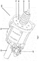
- Fig. 2 shows the clutch servo assembly 100 in a perspective view.
- the clutch servo assembly 100 comprises a pneumatic body 10, an actuator body 20 is connected to the pneumatic body, and a pilot valve associated with the pneumatic body 10.
- the pneumatic body 10 and the actuator or hydraulic body 20, are arranged in line, wherein the pneumatic pilot valve 30 is arranged adjacent to the actuator or hydraulic body 20.
- An actuator rod or a hydraulic rod is arranged in the actuator body 20 and moves, driven by the hydraulic pressure or any other workable force generated, in the direction of the pneumatic body 10, in order to open the pilot valve 30.
- the clutch servo assembly 100 further comprises a boot 60, in particular formed from a rubber material, operatively coupled to the push rod 50.
- the boot 60 is directly or indirectly coupled to movable actuator or hydraulic rod of the clutch servo assembly.
- the clutch servo assembly 100 further comprises a front plate 70, sealingly connected to the pneumatic body 10, wherein the number of exhaust conduits 40 is associated to the front plate to allow bidirectional flow of the pressurized air passing the front plate 70.
- the hydraulic or actuator rod 80 is operatively coupled with the push rod 50 and moving inside the actuator or hydraulic body 20 and at least partially within the pneumatic body 10 in order to actuate the push rod 50.
- the clutch servo assembly 100 further comprises a filter unit 90, configured to filter the flow of pressurized air passing the exhaust conduits 40 formed in the front plate 70, and to support the front plate 70 which is at least partly elastic.
- the pneumatic body 10 comprises a high pressure chamber 11, a low pressure chamber 13, fluid-tightly separated from each other, and a separating member 15.
- the high pressure chamber 11 and the low pressure chamber 13 are separated by the separating member 15 which is movably mounted within the pneumatic body 10.
- the high pressure chamber 11 and the low pressure chamber 13 are connected in a fluid-conducting manner via an exhaust passage 17 formed within the housing of the pneumatic body 10.
- the separating member 15 is actuated by the actuator or hydraulic rod 80 and coupled to the push rod 50.
- the movement of the separating member 15 in order to drive the push rod 50 in the direction of the clutch 200 is supported by a support member 19 which is in this embodiment formed as a compression spring.
- the volume of the high pressure chamber 11 and the low pressure chamber 13 is changing depending on position of the separating member 15.
- the pressurized air inside the high pressure chamber 11 will be exhausted by passing an exhausting passage 17 connecting the high pressure chamber and the low pressure chamber.
- the pressurized air inside the low pressure chamber 13 will pass the filter unit 90 and the exhaust conduits 40 formed in the front plate 70.
- the filter unit has a number of recesses, in particular formed in the reinforcing plate 91.
- the circular front plate 70 comprises a sealing 71 which is formed as an O-ring sealing extending along the outer circumference of the front plate 70.
- the front plate 70 and the pneumatic body 10 are connected in a positive fit.
- the filter unit 90 is arranged adjacent to the front plate 70 and also connected to the pneumatic body 10 in a positive fit.
- the filter unit 90 comprises a reinforcing plate 91 which is, for example, made of a steel or another material providing a high stiffness and strength.
- the filter unit 90 further comprises a filter element 93 which is arranged between the front plate 70 and the reinforcing plate 91.
- the hydraulic pressure applied by forcing the foot pedal 300 inside the hydraulic or actuator body 20 actuates the actuator or hydraulic rod 80.
- this hydraulic pressure could be replaced with an electronic or mechanical or any other workable force producing means. Therefore, hydraulic means is provided only for illustrative purposes and the hydraulic actuator could be replace with electronic or mechanical actuator as will be apparent to a skilled person. Such modifications are however not discussed herewith for the sake of brevity.
- the hydraulic or actuator rod 80 moves from its position in the hydraulic or actuator body 20 in the direction similar to that of the pneumatic body 10.
- the movement of the hydraulic actuator rod 80 actuates the pneumatic pilot valve 30.
- pressurized air is flowing into the pneumatic body 10 and in particular into the high pressure chamber 11.
- the pressurized air in the high pressure chamber 11 and additionally the movement of the hydraulic or actuator rod 80 are the factors that force the push rod 50 in the direction of the clutch 200.
- the flow of pressurized air in the high pressure chamber 11 results in the movement of the separating member 15 and an increased chamber volume.
- the volume of the low pressure chamber 13 is reduced with the same rate as the volume of the high pressure chamber 11 increases.
- the push rod 50 After disengaging the clutch 200, the push rod 50 is forced into the start position by the air from the atmosphere entering low pressure chamber 13 in addition or instead of any restoration means that is ordinarily enabled when a driver takes the foot off of the clutch pedal.
- the separating member 15, which is operatively coupled to the push rod 50 is moved as well. In consequence, the volume of the high pressure chamber 11 is reduced and the volume of the low pressure chamber 13 increases.
- increasing the volume of the low pressure chamber 13 first a negative pressure sets in, until a stream of pressurized air from the high pressure chamber 13 is passing the exhaust passage 17 and another stream of air is passing the exhaust conduits 40.
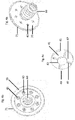
- Figs. 4a, b, c show the front plate 70 and the boot 60 as the monolithic part.
- the exhaust conduits 40 are formed in the front plate 70.
- the front plate 70 further comprises a sealing 79 extending along the circumference of the front plate 70.
- the exhaust conduits 40 are arranged coaxially to the front plate 70 and the boot 60 arranged in the middle of the front plate 70 and having a cylindrical recess in the middle.
- the exhaust conduits 40 are evenly distributed.
- Each exhaust conduit 40 has a flow restriction member causing the inbound and outbound flow resistance.
- Each flow restriction member 41 has a variable opening diameter defined by an inner diameter 43 and an outer diameter 45.
- the inner diameter 43 is formed by an arrangement of flaps 47 separated from each other by recesses 49, in particular slots.
- the flaps 47 are forming an elastic part which can be converted from an inner diameter 43 to an outer diameter 45.
- the filter unit 90 and in particular the filter element 93 is configured to support the flaps 47 in the inbound flow direction.
Landscapes
- Engineering & Computer Science (AREA)
- General Engineering & Computer Science (AREA)
- Mechanical Engineering (AREA)
- Physics & Mathematics (AREA)
- Fluid Mechanics (AREA)
- Chemical & Material Sciences (AREA)
- Analytical Chemistry (AREA)
- Hydraulic Clutches, Magnetic Clutches, Fluid Clutches, And Fluid Joints (AREA)
Abstract
Description
- The present invention relates to a clutch servo assembly. In accordance with an embodiment, the assembly comprises a pneumatic body, an actuator connected to the pneumatic body, a pneumatic pilot valve associated with the pneumatic body and configured to selectively supply pressurized air to the pneumatic body, an actuator rod movable within the actuator and at least partially within the pneumatic body, wherein the pneumatic body is in fluid communication with the atmosphere, wherein the pneumatic body is configured to allow bidirectional flow of air into and out of the pneumatic body. Further, the pneumatic body includes at least one exhaust conduit for resisting flow of air into the pneumatic body without completely closing the at least one exhaust conduit.
- Clutch servos have the function to proportionally "amplify" the foot pedal force by using air from the vehicle's compressed air system by disengaging clutch in order to shift the gears.
- The clutch servo is typically controlled hydraulically, in particular by a so called clutch master cylinder, and operates the clutch mechanically for example via a lever system. However, other control systems such as electronic control systems are also available instead of hydraulic control system.
- For instance, when a hydraulic control system is used, the hydraulic pressure generated by depressing a clutch pedal drives the hydraulic rod which in turn opens a pilot valve associated with the clutch servo and connects the inlet of the clutch servo to a pneumatic body in order to supply the required air pressure needed to disengage the clutch. After disengaging the clutch, it is necessary to have the possibility to dissipate the needed air out of the clutch servo.
- The time for dissipating the pressurized air determines the time needed for the gear shifting. The gear change time, for instance, may influence the fuel consumption of the vehicle due to resistance created due to the delay in gear shift.
- One of the objects of the present invention is to provide means for dissipating pressurized air in a controlled manner from the clutch servo without affecting its operation.
- As regards the clutch servo assembly, the object is achieved by the invention with a clutch servo assembly according to claim 1 where a clutch servo assembly is provided. In accordance with an embodiment, the assembly comprises a pneumatic body, an actuator connected to the pneumatic body, a pneumatic pilot valve associated with the pneumatic body and configured to selectively supply pressurized air to the pneumatic body, an actuator rod movable within the actuator and at least partially within the pneumatic body, wherein the pneumatic body is in fluid communication with the atmosphere, wherein the pneumatic body is configured to allow bidirectional flow of air into and out of the pneumatic body. Further, the pneumatic body includes at least one exhaust conduit for resisting flow of air into the pneumatic body without completely closing the at least one exhaust conduit.
- For instance, in the same embodiment, it is suggested that the exhaust conduit for resisting flow of air into the pneumatic body without completely closing the at least one exhaust conduit is provided with a first, outbound flow resistance and second, inbound flow resistance, wherein the second flow resistance is higher than the first flow resistance. Thus, for a given pressure inside the pneumatic body, the flow resistance determines the flow rate of the pressurized air being exhausted from the clutch servo and in particular the pneumatic body. Consequently, the time for exhausting is reduced compared to the time for charging or inhaling the pneumatic body. The development advantageously recognized that the time for exhausting the pneumatic body influences the time for shifting the gears by disengaging the clutch. Further, by reducing the inbound flow rate by the higher inbound flow resistance, the protection of clutch servo against dust and fluids from environment is improved.
- In a preferred embodiment, the exhaust conduit has a flow restriction member, configured to provide the first flow resistance as a function of the outbound flow of pressurized air and to provide the second flow resistance as a function of the inbound flow of pressurized air. Advantageously, the embodiment allows influencing the directional flow resistance of the exhaust conduits by a flow restriction member. Thus, conventional exhaust conduits can be used and will be modified by flow restriction members, which allows to reduce the cost for manufacturing.
- In a particular preferred embodiment, the clutch servo further comprises: a front plate sealingly connected to the pneumatic body, wherein the exhaust conduit is associated with the front plate and configured to allow bidirectional flow of pressurized air passing the front plate. The embodiment advantageously recognizes that the front plate describes a flat and in particular smooth part compared to a three-dimensional pneumatic body, and that the manufacturing costs can be reduced by associating the exhaust conduit with the front plate.
- In a preferred embodiment, the front plate and the exhaust conduit or conduits are monolithic. Thus, the plurality of components needed for the clutch servo assembly is reduced which leads to a reduction of manufacturing costs, as well as an improved sealing of the front plate.
- Preferably, the front plate and the exhaust conduit, in particular the flow restriction member, are formed from the same material, in particular a polymer. The embodiment advantageously recognizes that using the same material leads to a further reduction of manufacturing costs and allows a homogeneous characteristic of the front plate and the associated exhaust conduit and/or flow restriction member. By using a polymer material for the front plate and the exhaust conduit or conduits, the embodiment further advantageously recognizes that such a material has a suitable media resistance and is at least partly elastic, while at the same time being cost effective.
- In a preferred embodiment, the flow restriction member is configured such that the air flow rate is larger during outbound flow than inbound flow. For instance, this can be achieved by providing the flow restriction member that has a variable opening diameter, being larger at outbound flow of pressurized air, than at inbound flow of pressurized air. The embodiment advantageously recognizes that the opening diameter and the associated cross-sectional area passed by the flow of pressurized air determines the flow resistance and consequently the volumetric flow and/or flow rate. By changing the opening diameter, for example via elastic deformation, the embodiment allows a reversible conversion of the flow resistance depending on the flow direction.
- In a particular preferred embodiment, the flow restriction member has at least one flap separated by recesses, in particular curved and/or rectilinear slits, wherein the recesses are preferably aligned in a star-shape. Thus, the opening diameter determining the inbound and outbound flow resistance changes as a function of the deformation of said flaps. The recesses are giving an advantage to said deformation of said flap. The preferred alignment of the recesses allows an even deformation of the flaps when changing the opening diameter.
- Preferably, the front plate has a circular cross-sectional area, and a plurality of exhaust conduits. The plurality of exhaust conduits are evenly distributed in a circular pattern and arranged coaxially in the front plate.
- Preferably, some of the exhaust conduits are formed in accordance to any one of the preferred embodiments described herein above. Advantageously, the embodiment allows by the evenly distributed and coaxially arranged exhaust conduits a uniform pressure distributional front plate as well as a uniform flow of the pressurized air passing the front plate.
- Preferably, the front plate and the pneumatic body are coupled in a positive fit. Thus, the plurality of wear parts is reduced which leads to lower manufacturing costs and lower mechanical wear.
- In a preferred embodiment, the front plate comprises a sealing to protect the inside of the pneumatic body from environmental influences. Thus, the inside of the clutch servo is protected by a sealing which, in accordance with an embodiment is monolithic with the front plate. Accordingly, the number of rear parts is further reduced and the assembly is simplified.
- In a preferred embodiment, the pneumatic body further comprises a filter unit, configured to filter the bidirectional stream of pressurized air passing the exhaust conduits, wherein the filter unit is preferably assembled in contact with the front plate and configured to support the front plate. Advantageously, the embodiment allows to increase the protection of the clutch servo in particular by filtering the inbound flow in the exhaust conduits comprising dust and dirt from the environment. Accordingly, the lifetime of the clutch servo is increased by avoiding contamination of the pneumatic body. Further, even if contaminations do pass the exhaust conduits and reach the inside of the pneumatic body, the filter helps to avoid an undesired blockage of the exhaust conduits by filtering also the outbound flow which can comprise particles from the inside of the pneumatic body.
- Reasoned by the pressurized air inside the pneumatic body there are high forces acting on the front plate. The embodiment advantageously recognizes that the front plate is weakened by the at least one exhaust conduit and/or the elasticity and has to be supported. By assembling the filter unit in contact with the front plate, the filter unit has additional feature by supporting the front plate without the need of additional installation space.
- In a particular preferred embodiment, the filter unit comprises a reinforcing plate, configured to support the front plate, and a filter element, adjacent to the front plate, configured to filter the flow of pressurized air. Thus, a construction of the filter unit is provided which is appropriate to the needed functions. The reinforcing plate is configured to support the front plate as well as the filter element from the forces from the inside of the pneumatic body caused by the pressurized air. The reinforcing plate can for example be made of steel or another material having a high stiffness. The filter element can be formed from a lightweight material, for example a foam, in order to filter the flow of pressurized air. Appropriate materials for such a filter element are, for example, a foam, a fabric or a membrane. Such materials in general do not provide high stiffness or strength. Accordingly, it is advantageous to separate the functions required for filtering and supporting.
- In a preferred embodiment, the pneumatic body comprises a high pressure chamber, a low pressure chamber and a separating member, wherein the movement of the separating member within the pneumatic body changes the volume of the low and high pressure chambers respectively. For instance, such an arrangement leads to a changeable chamber volume, wherein the rate of volume change of the high pressure chamber corresponds to the rate of volume change of the low pressure chamber. It will be understood that correspondingly changing the volume of the high pressure chamber and the low pressure chamber means that by reducing the chamber volume of the high pressure chamber for example by 50 %, the volume of the low pressure chamber has to be extended by 50 %. Thus, the total volume of the pneumatic body remains constant and only the chamber volumes will change depending on the pressurized air supplied by the pilot valve or the exhausted air passing the exhaust conduits.
- Preferably, the high pressure chamber is in fluid communication with the pilot valve to allow pressurized air entering the pneumatic body and in particular the high pressure chamber, and wherein the low pressure chamber is in fluid communication with the exhaust conduit or conduits to allow pressurized air passing the exhaust conduit. Thus, there is a high pressure chamber communicating with the pilot valve in such a way that a pneumatic force is generated by the pressurized air inside the high pressure chamber acting on the clutch, and the low pressure chamber configured to receive the pressurized air which was needed for shifting the gear and allow the pressurized air to exhaust by passing the exhaust conduits.
- Preferably, the high pressure chamber and the low pressure chamber are in particular fluid-tightly separated from each other, and wherein the pneumatic body comprises an exhaust passage, configured for the fluid-conducting connection of the high pressure chamber and the low pressure chamber. The embodiment advantageously allows that the pressurized air inside the high pressure chamber, which is in particular fluid-tightly separated from the low pressure chamber, can pass the exhaust passage in order to get exhausted by the exhaust conduits. Thus, the number of exhaust conduits associated to the pneumatic body can be reduced, as the outbound flow of pressurized air from the high pressure chamber can be exhausted by the same exhaust conduits as the pressurized air from the low pressure chamber.
- In an exemplary embodiment, the clutch servo includes a hydraulic actuator with a hydraulic body. In accordance with this embodiment, the clutch servo further comprises a clutch spring, configured to apply a restoring force on the pneumatic body and/or the hydraulic body, and/or fluid-tightly coupled with the front plate. It will be understood, that applying a force can be realized direct or indirect for example by means of a lever system or a mechanical gear ratio. Advantageously, the embodiment recognizes that a clutch spring applying a restoring force on the pneumatic body and/or the hydraulic body provides an appropriate function to restore the hydraulic valve in a position, where the pilot valve is closed and no pressure is applied to the pneumatic body. Further, the coupling of the front plate and a boot facilitates providing an appropriate sealing against dust and dirt from the environment. Especially via monolithic forming of the boot and the front plate, the plurality of wear parts is reduced and the absence of joint has a positive effect on the sealing and the dirt resistance.
- Preferably, the hydraulic rod is operatively coupled to a push rod, wherein the pressurized air in the pneumatic body and the hydraulic pressure in the hydraulic body is configured to actuate the push rod to disengage a clutch. Thus, the foot pedal actuates a master cylinder providing a hydraulic pressure which in addition activates the pilot valve which enables additionally pneumatic pressure to actuate the push rod. The push rod enables to disengage the clutch which can be disposed at a distance to the clutch servo. When disengaging the clutch an outbound stream of pressurized air is passing the exhaust conduits, in particular to get exhausted from the inside of the low pressure chamber.
- Preferably, the hydraulic rod is configured and operatively coupled to be actuated by the push rod upon actuating force of the clutch spring acting on the push rod, to engage the clutch. Thus, the process of shifting the gears by disengaging the clutch is reversible by means of the clutch spring. The actuation force of the clutch spring can act in alternative or in addition to a pneumatic pressure in the pneumatic body acting on the push rod. After disengaging the clutch an inbound stream of pressurized air, which is significantly lower than the outbound stream of pressurized air, is passing the exhaust conduits. In addition, or in alternative, it is possible that pressurized air is passing the exhaust passage flowing from the high pressure chamber to the low pressure chamber.
- The object of the invention is in a second aspect further achieved by a front plate configured for being mounted in a clutch servo assembly according to the preferred embodiments of the invention described above, wherein the front plate has a mounting surface configured to be sealingly connected to the pneumatic body, in particular in a positive fit, wherein the front plate comprises the at least one exhaust conduit configured to allow bidirectional flow of pressurized air into and out of the pneumatic body, wherein the exhaust conduit has a first, outbound flow resistance and a second, inbound flow resistance, wherein the second flow resistance is higher than the first flow resistance. The embodiment according to the second aspect incorporates the advantages described above by providing a front plate configured to be connected to and used in a clutch servo assembly. The examples and preferred embodiments of the clutch servo assembly of the first aspect described above are also the preferred examples and preferred embodiments of the front plate and vice versa.
- With regard to the system, the object of the invention is achieved in a third aspect by a clutch actuation system comprising a clutch and a clutch servo assembly according to the preferred embodiments of the first aspect of invention described above. The examples and preferred embodiments of the clutch servo assembly described above are also the preferred examples and preferred embodiments of the clutch actuation system comprising said clutch servo assembly.
- The object of the invention is in a fourth aspect further achieved by a motor vehicle comprising a clutch actuation system, in particular a clutch actuation system according to any one of the embodiments of the third aspect of the invention described above, having a clutch and a clutch servo assembly, in particular a clutch servo assembly according to the first aspect of the invention. The motor vehicle preferably comprises a bell housing of a gear box of a motor, and wherein the clutch servo assembly is mounted on said bell housing of said gear box of the motor. The examples and preferred embodiments of the clutch servo assembly described above are also the preferred examples and preferred embodiments of the motor vehicle comprising said clutch servo assembly.
- For a more complete understanding of the invention, the invention will now be described in detail with reference to the accompanying drawing. The detailed description will illustrate and describe what is considered as a preferred embodiment of the invention. It should of course be understood that various modifications and changes in form or detail could readily be made without departing from the spirit of the invention. It is therefore intended that the invention may not be limited to the exact form and detail shown and described herein, nor to anything less than the whole of the invention disclosed herein and as claimed hereinafter. Further, the features described in the description, the drawings and the claims disclosing the invention may be essential for the invention considered alone or in combination. In particular, any reference signs in the claims shall not be construed as limiting the scope of the invention. The wording "comprising" does not exclude other elements or steps. The wording "a" or "an" does not exclude a plurality.
- This invention will now be described with reference to the accompanying drawings which illustrate, by way of example and not by way of limitation, one of several possible embodiments of the clutch servo proposed herein, and wherein
- Fig. 1
- illustrates a motor vehicle schematically,
- Fig. 2
- illustrates a clutch servo assembly for the motor vehicle according to
Fig. 1 in a perspective view, - Fig. 3
- illustrates a sectional view of the clutch servo assembly according to
Fig. 2 , - Fig. 4
- illustrates a front plate having exhaust conduits for the clutch servo assembly according to
Fig. 2 . -
Fig. 1 shows a motor vehicle 10000 in principle. The motor vehicle 10000 comprises aclutch actuation system 1000 having aclutch servo assembly 100, afoot pedal 300, operatively associated with theclutch servo assembly 100, and a clutch 200 for connection and disconnection of two rotating shafts of the motor vehicle 10000. - When a driver depresses the foot pedal, the generated force is amplified by the
clutch servo 100 in order to disengage the clutch 200 when changing the gears of the motor vehicle 10000. - The
clutch servo assembly 100 is shown in an operation state not yet acting on the clutch 200 in a principle manner. - It is noted that for the purposes of the illustration, the present invention is described where the
clutch servo assembly 100 includes a hydraulic actuator (not labeled in figure) with ahydraulic body 20. However, it is noted that the entire hydraulic actuator and any other hydraulically actuated components can be replaced either component wise or completely with an electrical actuator and/or any other actuators available in the market currently. It will be in any case, noted by the skilled person that such modifications are apparent. In accordance with the present illustrative embodiment, theclutch servo assembly 100 comprises apneumatic body 10 and the hydraulic body 20 (or actuator body) which is assembled or connected to thepneumatic body 10. Theclutch servo assembly 100 further comprises apneumatic pilot valve 30 which is associated with thepneumatic body 10 to supply pressurized air, and a number ofexhaust conduits 40, which are in fluid communication with thepneumatic body 10. - The
pneumatic body 10 and thehydraulic body 20 are operatively coupled with apush rod 50 which is configured to disengage the clutch 200. - The
push rod 50 is actuated by a hydraulic rod (not shown inFig. 1 , but see reference sign '80' ofFig. 3 ) or an actuator which is movable inside the actuator body orhydraulic body 20 and thepneumatic body 10 in response of a hydraulic pressure in the hydraulic body or any other workable force generated by the actuator body (e.g., electronic actuator). The hydraulic rod or the actuator rod is further configured to actuate thepneumatic pilot valve 30. - In accordance with the present invention, at least one
exhaust conduit 40 is provided for resisting flow of air into the pneumatic body without completely closing the at least one exhaust conduit (40). In the illustrative example here, more than one exhaust conduit is shown. Theexhaust conduits 40 are in fluid communication with thepneumatic body 10 for bidirectional flow of pressurized air between the inside of thepneumatic body 10 and in particular a bell housing in which theclutch servo assembly 100 is disposed. Theexhaust conduits 40 have an inbound flow resistance and an outbound flow resistance, wherein the inbound flow resistance is higher than the outbound flow resistance. - In the following, the function of the motor vehicle when changing the gears is described as an illustrative example using hydraulic means.
- For changing the gears of a motor vehicle 10000 a hydraulic pressure is generated by depressing the
foot pedal 300 which applies a hydraulic pressure, in general by means of a so-called master cylinder. Driven by said hydraulic pressure, which is applied in the hydraulic body, the hydraulic rod moves in the hydraulic andpneumatic body pneumatic valve 30. Thereby the movement of the hydraulic rod is allowing the pressurized air to enter thepneumatic body 10 and applying force on thepush rod 50 which disengages the clutch 200. When the hydraulic pressure is removed from thehydraulic body 20, thepush rod 50 moves backwards and thereby exhausting the pressurized air from thepneumatic body 10 through theexhaust conduits 40. - In accordance with an exemplary embodiment,
Fig. 2 shows theclutch servo assembly 100 in a perspective view. Theclutch servo assembly 100 comprises apneumatic body 10, anactuator body 20 is connected to the pneumatic body, and a pilot valve associated with thepneumatic body 10. Thepneumatic body 10 and the actuator orhydraulic body 20, are arranged in line, wherein thepneumatic pilot valve 30 is arranged adjacent to the actuator orhydraulic body 20. An actuator rod or a hydraulic rod is arranged in theactuator body 20 and moves, driven by the hydraulic pressure or any other workable force generated, in the direction of thepneumatic body 10, in order to open thepilot valve 30. - The
clutch servo assembly 100 further comprises aboot 60, in particular formed from a rubber material, operatively coupled to thepush rod 50. For instance, theboot 60 is directly or indirectly coupled to movable actuator or hydraulic rod of the clutch servo assembly. - The
clutch servo assembly 100 further comprises afront plate 70, sealingly connected to thepneumatic body 10, wherein the number ofexhaust conduits 40 is associated to the front plate to allow bidirectional flow of the pressurized air passing thefront plate 70. - In accordance with an embodiment, the
boot 60 and thefront plate 70 are formed monolithic in order to improve the sealing of the pneumatic body. - As in particular shown in the sectional view of
Fig. 3 , the hydraulic oractuator rod 80 is operatively coupled with thepush rod 50 and moving inside the actuator orhydraulic body 20 and at least partially within thepneumatic body 10 in order to actuate thepush rod 50. In the illustrated embodiment, theclutch servo assembly 100 further comprises afilter unit 90, configured to filter the flow of pressurized air passing theexhaust conduits 40 formed in thefront plate 70, and to support thefront plate 70 which is at least partly elastic. - The
pneumatic body 10 comprises ahigh pressure chamber 11, alow pressure chamber 13, fluid-tightly separated from each other, and a separatingmember 15. Thehigh pressure chamber 11 and thelow pressure chamber 13 are separated by the separatingmember 15 which is movably mounted within thepneumatic body 10. Thehigh pressure chamber 11 and thelow pressure chamber 13 are connected in a fluid-conducting manner via anexhaust passage 17 formed within the housing of thepneumatic body 10. - The separating
member 15 is actuated by the actuator orhydraulic rod 80 and coupled to thepush rod 50. The movement of the separatingmember 15 in order to drive thepush rod 50 in the direction of the clutch 200 is supported by asupport member 19 which is in this embodiment formed as a compression spring. - The volume of the
high pressure chamber 11 and thelow pressure chamber 13 is changing depending on position of the separatingmember 15. When reducing the volume of thehigh pressure chamber 11, the pressurized air inside thehigh pressure chamber 11 will be exhausted by passing anexhausting passage 17 connecting the high pressure chamber and the low pressure chamber. When reducing the volume of thelow pressure chamber 13, the pressurized air inside thelow pressure chamber 13 will pass thefilter unit 90 and theexhaust conduits 40 formed in thefront plate 70. For this purpose, the filter unit has a number of recesses, in particular formed in the reinforcingplate 91. - The circular
front plate 70 comprises a sealing 71 which is formed as an O-ring sealing extending along the outer circumference of thefront plate 70. Thefront plate 70 and thepneumatic body 10 are connected in a positive fit. - The
filter unit 90 is arranged adjacent to thefront plate 70 and also connected to thepneumatic body 10 in a positive fit.
Thefilter unit 90 comprises a reinforcingplate 91 which is, for example, made of a steel or another material providing a high stiffness and strength. Thefilter unit 90 further comprises afilter element 93 which is arranged between thefront plate 70 and the reinforcingplate 91. - In the following, the function of the clutch servo is described as an illustrative example.
- In one exemplary embodiment, the hydraulic pressure applied by forcing the
foot pedal 300 inside the hydraulic oractuator body 20 actuates the actuator orhydraulic rod 80. In another embodiment, this hydraulic pressure could be replaced with an electronic or mechanical or any other workable force producing means. Therefore, hydraulic means is provided only for illustrative purposes and the hydraulic actuator could be replace with electronic or mechanical actuator as will be apparent to a skilled person. Such modifications are however not discussed herewith for the sake of brevity. - In any case, the hydraulic or
actuator rod 80 moves from its position in the hydraulic oractuator body 20 in the direction similar to that of thepneumatic body 10. The movement of thehydraulic actuator rod 80 actuates thepneumatic pilot valve 30. When opening thepilot valve 30, pressurized air is flowing into thepneumatic body 10 and in particular into thehigh pressure chamber 11. The pressurized air in thehigh pressure chamber 11 and additionally the movement of the hydraulic oractuator rod 80 are the factors that force thepush rod 50 in the direction of the clutch 200. The flow of pressurized air in thehigh pressure chamber 11 results in the movement of the separatingmember 15 and an increased chamber volume. The volume of thelow pressure chamber 13 is reduced with the same rate as the volume of thehigh pressure chamber 11 increases. The pressurized air in thelow pressure chamber 13 has to be exhausted very quickly in order to enable a fast changing of the gears. In order to dissipate the remaining pressurized air in thelow pressure chamber 13, the air is passing theexhaust conduits 40 in thefront plate 70. The outbound flow of the pressurized air has a higher flow rate of volume reasoned by the reduced outbound flow resistance of theexhaust conduits 40. - After disengaging the clutch 200, the
push rod 50 is forced into the start position by the air from the atmosphere enteringlow pressure chamber 13 in addition or instead of any restoration means that is ordinarily enabled when a driver takes the foot off of the clutch pedal. When regressing thepush rod 50, the separatingmember 15, which is operatively coupled to thepush rod 50, is moved as well. In consequence, the volume of thehigh pressure chamber 11 is reduced and the volume of thelow pressure chamber 13 increases. When increasing the volume of thelow pressure chamber 13, first a negative pressure sets in, until a stream of pressurized air from thehigh pressure chamber 13 is passing theexhaust passage 17 and another stream of air is passing theexhaust conduits 40. The stream passing theexhaust conduits 40 has a lower flow rate of volume compared to the outbound stream of pressurized air. The inbound stream of pressurized air is first filtered by thefilter element 93 of thefilter unit 90 in order to avoid contamination of thepneumatic body 10. -
Figs. 4a, b, c show thefront plate 70 and theboot 60 as the monolithic part. Theexhaust conduits 40 are formed in thefront plate 70. Thefront plate 70 further comprises a sealing 79 extending along the circumference of thefront plate 70. As illustrated inFig. 4b and 4c , theexhaust conduits 40 are arranged coaxially to thefront plate 70 and theboot 60 arranged in the middle of thefront plate 70 and having a cylindrical recess in the middle. Theexhaust conduits 40 are evenly distributed. Eachexhaust conduit 40 has a flow restriction member causing the inbound and outbound flow resistance. Eachflow restriction member 41 has a variable opening diameter defined by aninner diameter 43 and anouter diameter 45. Theinner diameter 43 is formed by an arrangement offlaps 47 separated from each other byrecesses 49, in particular slots. Theflaps 47 are forming an elastic part which can be converted from aninner diameter 43 to anouter diameter 45. Thefilter unit 90 and in particular thefilter element 93 is configured to support theflaps 47 in the inbound flow direction. When the pressurized air is flowing outbound from the inside of thepneumatic body 10, there is no support for theelastic flaps 47 of theflow restriction members 41 of and theflaps 47 will bend outside caused by the outbound flow of the pressurized air. Thus, a conversion of the effective opening diameter of theexhaust conduits 40 is causing a higher flow rate of the pressurized air flowing in the outbound direction compared to the volume rate of inbound flowing pressurized air when the pressure remains constant. -
- 10
- Pneumatic body
- 11
- High pressure chamber
- 13
- Low pressure chamber
- 15
- Separating member
- 17
- Exhaust passage
- 19
- Support element (Spring)
- 20
- Hydraulic or actuator body
- 30
- Pilot valve
- M
- Master cylinder
- 40
- Exhaust conduit
- 41
- Flow restriction member
- 43
- Inner diameter
- 45
- Outer diameter
- 47
- Flaps
- 49
- Recesses
- 50
- Push rod
- 60
- Boot
- 70
- Front plate
- 71
- Sealing
- 80
- Hydraulic or actuator rod
- 90
- Filter unit
- 91
- Reinforcing plate
- 93
- Filter element
- 100
- Clutch servo
- 200
- Clutch
- 300
- Pedal
- 1000
- Clutch actuation system
- 10000
- Motor vehicle
Claims (16)
- Clutch servo assembly (100), comprising:- a pneumatic body (10),- an actuator connected to the pneumatic body (10),- a pneumatic pilot valve (30) associated with the pneumatic body (10) and configured to selectively supply pressurized air to the pneumatic body (10),- an actuator rod (80) movable within the actuator (20) and at least partially within the pneumatic body (10),wherein the pneumatic body (10) is in fluid communication with the atmosphere, wherein the pneumatic body (10) is configured to allow bidirectional flow of air into and out of the pneumatic body (10),
characterized in that the pneumatic body (10) includes at least one exhaust conduit (40) for resisting flow of air into the pneumatic body (10) without completely closing the at least one exhaust conduit (40). - Clutch servo assembly (100), according to claim 1,
wherein the at least one exhaust conduit (40) has a flow restriction member (41), configured to provide the outbound flow resistance as a function of the outbound flow of pressurized air and to provide the inbound flow resistance as a function of the inbound flow of pressurized air. - Clutch servo assembly (100), according to any one of the claims 1 or 2, further comprising- a front plate (70) sealingly connected to the pneumatic body (10), wherein the exhaust conduit or conduits (40) are associated with the front plate (70) and configured to allow bidirectional flow of pressurized air passing the front plate (70).
- Clutch servo assembly (100), according to claim 3,
wherein the front plate (70) and the exhaust conduit or conduits (40) are monolithic. - Clutch servo assembly (100), according to any one of the claims 3 or 4, wherein the front plate (70) and the exhaust conduits (40), in particular the flow restriction member (41), are formed from the same material, in particular a polymer.
- Clutch servo assembly (100), according to any one of the claims 2 to 5, wherein the flow restriction member (41) is configured such that the air flow rate is larger during outbound flow than inbound flow.
- Clutch servo assembly (100), according to any one of the claims 2 to 6, wherein the flow restriction member (41) has at least one flap (47) separated by recesses (49)incorporating curved and/or rectilinear slits.
- Clutch servo assembly (100), according to any one of the claims 3 to 7, wherein the front plate (70) has a circular cross-sectional area, and a plurality of exhaust conduits
wherein the plurality of exhaust conduits (40) are evenly distributed in a circular pattern and arranged coaxially in the front plate (70). - Clutch servo assembly (100), according to any one of the claims 3 to 8, wherein the front plate (70) and the pneumatic body (10) are coupled in a positive fit.
- Clutch servo assembly (100) according to any one of the claims 3 to 9, wherein the front plate (70) comprises a sealing (71) to protect the inside of the pneumatic body (10) from environmental influences.
- Clutch servo assembly (100) according to any one of the preceding claims,
wherein the pneumatic body (10) further comprises a filter unit (90), configured to filter air passing the exhaust conduits (40),
wherein the filter unit (90) is preferably assembled in contact with the front plate (70) and configured to support the front plate (70). - Clutch servo assembly (100) according to claim 11,
wherein the filter unit (90) comprises a reinforcing plate (91), configured to support the front plate (70), and a filter element (93), preferably disposed adjacent to the front plate (70), and configured to filter the flow of pressurized ai r. - Clutch servo assembly (100) according to any one of the preceding claims,
wherein the pneumatic body (10) comprises a high pressure chamber (11) and a low pressure chamber (13) and a separating member (15), wherein the movement of the separating member (15) within the pneumatic body (10) changes the volume of the low and high pressure chambers respectively . - Clutch servo assembly (100), according to claim 13,
wherein the high pressure chamber (11) is in fluid communication with the pilot valve (30) to allow pressurized air entering the pneumatic body (10) and in particular the high pressure chamber (11), and
wherein the low pressure chamber (13) is in fluid communication with the exhaust conduit or conduits (40) to allow pressurized air passing the exhaust conduit. - Clutch servo assembly (100) according to any one of the claims 13 and 14,
wherein the high pressure chamber (11) and the low pressure chamber (13) are in particular fluid-tightly separated from each other, and
wherein the pneumatic body (10) comprises an exhaust passage (17), configured for the fluid-conducting connection of the high pressure chamber (11) and the low pressure chamber (13). - Clutch actuation system (1000), comprising a clutch and the clutch servo assembly in accordance with any one of the claims 1 to 18.
Priority Applications (2)
| Application Number | Priority Date | Filing Date | Title |
|---|---|---|---|
| EP19177381.1A EP3744994B1 (en) | 2019-05-29 | 2019-05-29 | Clutch servo assembly, clutch actuation system and a motor vehicle |
| CN202010435275.3A CN112013045B (en) | 2019-05-29 | 2020-05-21 | Clutch servo assembly, clutch actuating system and motor vehicle |
Applications Claiming Priority (1)
| Application Number | Priority Date | Filing Date | Title |
|---|---|---|---|
| EP19177381.1A EP3744994B1 (en) | 2019-05-29 | 2019-05-29 | Clutch servo assembly, clutch actuation system and a motor vehicle |
Publications (2)
| Publication Number | Publication Date |
|---|---|
| EP3744994A1 true EP3744994A1 (en) | 2020-12-02 |
| EP3744994B1 EP3744994B1 (en) | 2022-10-05 |
Family
ID=66821007
Family Applications (1)
| Application Number | Title | Priority Date | Filing Date |
|---|---|---|---|
| EP19177381.1A Active EP3744994B1 (en) | 2019-05-29 | 2019-05-29 | Clutch servo assembly, clutch actuation system and a motor vehicle |
Country Status (2)
| Country | Link |
|---|---|
| EP (1) | EP3744994B1 (en) |
| CN (1) | CN112013045B (en) |
Cited By (1)
| Publication number | Priority date | Publication date | Assignee | Title |
|---|---|---|---|---|
| CN113048164A (en) * | 2021-03-24 | 2021-06-29 | 浙江科力车辆控制系统有限公司 | Internal exhaust type clutch booster |
Citations (2)
| Publication number | Priority date | Publication date | Assignee | Title |
|---|---|---|---|---|
| EP2053260A2 (en) * | 2007-10-25 | 2009-04-29 | KNORR-BREMSE Systeme für Nutzfahrzeuge GmbH | Clutch booster |
| CN101858393B (en) * | 2010-07-07 | 2012-11-28 | 瑞立集团瑞安汽车零部件有限公司 | Clutch booster |
Family Cites Families (3)
| Publication number | Priority date | Publication date | Assignee | Title |
|---|---|---|---|---|
| US20120144945A1 (en) * | 2010-12-13 | 2012-06-14 | GM Global Technology Operations LLC | Single-piston three-position hydraulic actuator |
| US8776637B2 (en) * | 2012-01-06 | 2014-07-15 | Gm Global Technology Operations, Llc | Hydraulic fluid transfer assembly |
| CN205350136U (en) * | 2016-03-03 | 2016-06-29 | 山推工程机械股份有限公司 | Buffer is controld in separation and reunion of mechanical type road roller |
-
2019
- 2019-05-29 EP EP19177381.1A patent/EP3744994B1/en active Active
-
2020
- 2020-05-21 CN CN202010435275.3A patent/CN112013045B/en active Active
Patent Citations (2)
| Publication number | Priority date | Publication date | Assignee | Title |
|---|---|---|---|---|
| EP2053260A2 (en) * | 2007-10-25 | 2009-04-29 | KNORR-BREMSE Systeme für Nutzfahrzeuge GmbH | Clutch booster |
| CN101858393B (en) * | 2010-07-07 | 2012-11-28 | 瑞立集团瑞安汽车零部件有限公司 | Clutch booster |
Cited By (1)
| Publication number | Priority date | Publication date | Assignee | Title |
|---|---|---|---|---|
| CN113048164A (en) * | 2021-03-24 | 2021-06-29 | 浙江科力车辆控制系统有限公司 | Internal exhaust type clutch booster |
Also Published As
| Publication number | Publication date |
|---|---|
| EP3744994B1 (en) | 2022-10-05 |
| CN112013045A (en) | 2020-12-01 |
| CN112013045B (en) | 2024-03-01 |
Similar Documents
| Publication | Publication Date | Title |
|---|---|---|
| CN107757589A (en) | Electric brake system | |
| JPH0624922B2 (en) | Valve assembly for controlling pneumatic brake booster | |
| US6729132B2 (en) | Remotely and directly pedal operated hydraulic compact booster for bi-directional braking | |
| KR100730399B1 (en) | Modular electronic brake valve for air brakes vehicles | |
| EP3744994B1 (en) | Clutch servo assembly, clutch actuation system and a motor vehicle | |
| KR20070102715A (en) | Vehicle brake system | |
| EP4194669B1 (en) | Brake valve with silencer or spout connector | |
| CN1087245C (en) | Power brack for motor vehicles | |
| US10752226B2 (en) | Brake device for a hydraulic motor vehicle brake system | |
| JPH04230455A (en) | Anti-lock brake system of automobile | |
| US7360359B2 (en) | Hydraulic system having an emergency release mechanism for a clutch having servo-assisted pedal actuation | |
| US3482485A (en) | Fluid pressure servomotor | |
| US3222869A (en) | Dual hydraulic brake systems and brake booster mechanisms therefor | |
| EP0629535B1 (en) | Pneumatic booster | |
| CN1153725A (en) | Electronic control type brake booster for vehicle | |
| US3434285A (en) | Duo servomotor valve means | |
| JP4072735B2 (en) | Pneumatic booster with reduced load and hysteresis | |
| US20230031027A1 (en) | Pneumatic brake pedal module | |
| US3049099A (en) | Reaction producing structure | |
| CN104822958A (en) | separation system | |
| US6805037B2 (en) | Brake booster sensor | |
| GB2028444A (en) | Brake force regulator | |
| RU100982U1 (en) | HYDRAULIC VALVE TWO-CIRCUIT BRAKE SYSTEM | |
| WO2002102635A3 (en) | Electropneumatic double control valve comprising a sealing arrangement | |
| US4366742A (en) | Hydraulic force multiplying device |
Legal Events
| Date | Code | Title | Description |
|---|---|---|---|
| PUAI | Public reference made under article 153(3) epc to a published international application that has entered the european phase |
Free format text: ORIGINAL CODE: 0009012 |
|
| STAA | Information on the status of an ep patent application or granted ep patent |
Free format text: STATUS: THE APPLICATION HAS BEEN PUBLISHED |
|
| AK | Designated contracting states |
Kind code of ref document: A1 Designated state(s): AL AT BE BG CH CY CZ DE DK EE ES FI FR GB GR HR HU IE IS IT LI LT LU LV MC MK MT NL NO PL PT RO RS SE SI SK SM TR |
|
| AX | Request for extension of the european patent |
Extension state: BA ME |
|
| RAP3 | Party data changed (applicant data changed or rights of an application transferred) |
Owner name: ZF CV SYSTEMS EUROPE BV |
|
| STAA | Information on the status of an ep patent application or granted ep patent |
Free format text: STATUS: REQUEST FOR EXAMINATION WAS MADE |
|
| 17P | Request for examination filed |
Effective date: 20210602 |
|
| RBV | Designated contracting states (corrected) |
Designated state(s): AL AT BE BG CH CY CZ DE DK EE ES FI FR GB GR HR HU IE IS IT LI LT LU LV MC MK MT NL NO PL PT RO RS SE SI SK SM TR |
|
| GRAP | Despatch of communication of intention to grant a patent |
Free format text: ORIGINAL CODE: EPIDOSNIGR1 |
|
| STAA | Information on the status of an ep patent application or granted ep patent |
Free format text: STATUS: GRANT OF PATENT IS INTENDED |
|
| RIC1 | Information provided on ipc code assigned before grant |
Ipc: F16D 25/08 20060101ALI20220630BHEP Ipc: F16D 48/04 20060101AFI20220630BHEP |
|
| INTG | Intention to grant announced |
Effective date: 20220727 |
|
| GRAS | Grant fee paid |
Free format text: ORIGINAL CODE: EPIDOSNIGR3 |
|
| GRAA | (expected) grant |
Free format text: ORIGINAL CODE: 0009210 |
|
| STAA | Information on the status of an ep patent application or granted ep patent |
Free format text: STATUS: THE PATENT HAS BEEN GRANTED |
|
| AK | Designated contracting states |
Kind code of ref document: B1 Designated state(s): AL AT BE BG CH CY CZ DE DK EE ES FI FR GB GR HR HU IE IS IT LI LT LU LV MC MK MT NL NO PL PT RO RS SE SI SK SM TR |
|
| REG | Reference to a national code |
Ref country code: GB Ref legal event code: FG4D |
|
| REG | Reference to a national code |
Ref country code: CH Ref legal event code: EP |
|
| REG | Reference to a national code |
Ref country code: AT Ref legal event code: REF Ref document number: 1522914 Country of ref document: AT Kind code of ref document: T Effective date: 20221015 |
|
| REG | Reference to a national code |
Ref country code: DE Ref legal event code: R096 Ref document number: 602019020198 Country of ref document: DE |
|
| REG | Reference to a national code |
Ref country code: IE Ref legal event code: FG4D |
|
| REG | Reference to a national code |
Ref country code: LT Ref legal event code: MG9D |
|
| REG | Reference to a national code |
Ref country code: NL Ref legal event code: MP Effective date: 20221005 |
|
| REG | Reference to a national code |
Ref country code: AT Ref legal event code: MK05 Ref document number: 1522914 Country of ref document: AT Kind code of ref document: T Effective date: 20221005 |
|
| PG25 | Lapsed in a contracting state [announced via postgrant information from national office to epo] |
Ref country code: NL Free format text: LAPSE BECAUSE OF FAILURE TO SUBMIT A TRANSLATION OF THE DESCRIPTION OR TO PAY THE FEE WITHIN THE PRESCRIBED TIME-LIMIT Effective date: 20221005 |
|
| PG25 | Lapsed in a contracting state [announced via postgrant information from national office to epo] |
Ref country code: SE Free format text: LAPSE BECAUSE OF FAILURE TO SUBMIT A TRANSLATION OF THE DESCRIPTION OR TO PAY THE FEE WITHIN THE PRESCRIBED TIME-LIMIT Effective date: 20221005 Ref country code: PT Free format text: LAPSE BECAUSE OF FAILURE TO SUBMIT A TRANSLATION OF THE DESCRIPTION OR TO PAY THE FEE WITHIN THE PRESCRIBED TIME-LIMIT Effective date: 20230206 Ref country code: NO Free format text: LAPSE BECAUSE OF FAILURE TO SUBMIT A TRANSLATION OF THE DESCRIPTION OR TO PAY THE FEE WITHIN THE PRESCRIBED TIME-LIMIT Effective date: 20230105 Ref country code: LT Free format text: LAPSE BECAUSE OF FAILURE TO SUBMIT A TRANSLATION OF THE DESCRIPTION OR TO PAY THE FEE WITHIN THE PRESCRIBED TIME-LIMIT Effective date: 20221005 Ref country code: FI Free format text: LAPSE BECAUSE OF FAILURE TO SUBMIT A TRANSLATION OF THE DESCRIPTION OR TO PAY THE FEE WITHIN THE PRESCRIBED TIME-LIMIT Effective date: 20221005 Ref country code: ES Free format text: LAPSE BECAUSE OF FAILURE TO SUBMIT A TRANSLATION OF THE DESCRIPTION OR TO PAY THE FEE WITHIN THE PRESCRIBED TIME-LIMIT Effective date: 20221005 Ref country code: AT Free format text: LAPSE BECAUSE OF FAILURE TO SUBMIT A TRANSLATION OF THE DESCRIPTION OR TO PAY THE FEE WITHIN THE PRESCRIBED TIME-LIMIT Effective date: 20221005 |
|
| PG25 | Lapsed in a contracting state [announced via postgrant information from national office to epo] |
Ref country code: RS Free format text: LAPSE BECAUSE OF FAILURE TO SUBMIT A TRANSLATION OF THE DESCRIPTION OR TO PAY THE FEE WITHIN THE PRESCRIBED TIME-LIMIT Effective date: 20221005 Ref country code: PL Free format text: LAPSE BECAUSE OF FAILURE TO SUBMIT A TRANSLATION OF THE DESCRIPTION OR TO PAY THE FEE WITHIN THE PRESCRIBED TIME-LIMIT Effective date: 20221005 Ref country code: LV Free format text: LAPSE BECAUSE OF FAILURE TO SUBMIT A TRANSLATION OF THE DESCRIPTION OR TO PAY THE FEE WITHIN THE PRESCRIBED TIME-LIMIT Effective date: 20221005 Ref country code: IS Free format text: LAPSE BECAUSE OF FAILURE TO SUBMIT A TRANSLATION OF THE DESCRIPTION OR TO PAY THE FEE WITHIN THE PRESCRIBED TIME-LIMIT Effective date: 20230205 Ref country code: HR Free format text: LAPSE BECAUSE OF FAILURE TO SUBMIT A TRANSLATION OF THE DESCRIPTION OR TO PAY THE FEE WITHIN THE PRESCRIBED TIME-LIMIT Effective date: 20221005 Ref country code: GR Free format text: LAPSE BECAUSE OF FAILURE TO SUBMIT A TRANSLATION OF THE DESCRIPTION OR TO PAY THE FEE WITHIN THE PRESCRIBED TIME-LIMIT Effective date: 20230106 |
|
| REG | Reference to a national code |
Ref country code: DE Ref legal event code: R097 Ref document number: 602019020198 Country of ref document: DE |
|
| P01 | Opt-out of the competence of the unified patent court (upc) registered |
Effective date: 20230528 |
|
| PG25 | Lapsed in a contracting state [announced via postgrant information from national office to epo] |
Ref country code: SM Free format text: LAPSE BECAUSE OF FAILURE TO SUBMIT A TRANSLATION OF THE DESCRIPTION OR TO PAY THE FEE WITHIN THE PRESCRIBED TIME-LIMIT Effective date: 20221005 Ref country code: RO Free format text: LAPSE BECAUSE OF FAILURE TO SUBMIT A TRANSLATION OF THE DESCRIPTION OR TO PAY THE FEE WITHIN THE PRESCRIBED TIME-LIMIT Effective date: 20221005 Ref country code: EE Free format text: LAPSE BECAUSE OF FAILURE TO SUBMIT A TRANSLATION OF THE DESCRIPTION OR TO PAY THE FEE WITHIN THE PRESCRIBED TIME-LIMIT Effective date: 20221005 Ref country code: DK Free format text: LAPSE BECAUSE OF FAILURE TO SUBMIT A TRANSLATION OF THE DESCRIPTION OR TO PAY THE FEE WITHIN THE PRESCRIBED TIME-LIMIT Effective date: 20221005 Ref country code: CZ Free format text: LAPSE BECAUSE OF FAILURE TO SUBMIT A TRANSLATION OF THE DESCRIPTION OR TO PAY THE FEE WITHIN THE PRESCRIBED TIME-LIMIT Effective date: 20221005 |
|
| PGFP | Annual fee paid to national office [announced via postgrant information from national office to epo] |
Ref country code: FR Payment date: 20230517 Year of fee payment: 5 |
|
| PLBE | No opposition filed within time limit |
Free format text: ORIGINAL CODE: 0009261 |
|
| STAA | Information on the status of an ep patent application or granted ep patent |
Free format text: STATUS: NO OPPOSITION FILED WITHIN TIME LIMIT |
|
| PG25 | Lapsed in a contracting state [announced via postgrant information from national office to epo] |
Ref country code: SK Free format text: LAPSE BECAUSE OF FAILURE TO SUBMIT A TRANSLATION OF THE DESCRIPTION OR TO PAY THE FEE WITHIN THE PRESCRIBED TIME-LIMIT Effective date: 20221005 Ref country code: AL Free format text: LAPSE BECAUSE OF FAILURE TO SUBMIT A TRANSLATION OF THE DESCRIPTION OR TO PAY THE FEE WITHIN THE PRESCRIBED TIME-LIMIT Effective date: 20221005 |
|
| 26N | No opposition filed |
Effective date: 20230706 |
|
| PGFP | Annual fee paid to national office [announced via postgrant information from national office to epo] |
Ref country code: GB Payment date: 20230522 Year of fee payment: 5 |
|
| PG25 | Lapsed in a contracting state [announced via postgrant information from national office to epo] |
Ref country code: SI Free format text: LAPSE BECAUSE OF FAILURE TO SUBMIT A TRANSLATION OF THE DESCRIPTION OR TO PAY THE FEE WITHIN THE PRESCRIBED TIME-LIMIT Effective date: 20221005 |
|
| REG | Reference to a national code |
Ref country code: CH Ref legal event code: PL |
|
| PG25 | Lapsed in a contracting state [announced via postgrant information from national office to epo] |
Ref country code: MC Free format text: LAPSE BECAUSE OF FAILURE TO SUBMIT A TRANSLATION OF THE DESCRIPTION OR TO PAY THE FEE WITHIN THE PRESCRIBED TIME-LIMIT Effective date: 20221005 |
|
| REG | Reference to a national code |
Ref country code: BE Ref legal event code: MM Effective date: 20230531 |
|
| PG25 | Lapsed in a contracting state [announced via postgrant information from national office to epo] |
Ref country code: MC Free format text: LAPSE BECAUSE OF FAILURE TO SUBMIT A TRANSLATION OF THE DESCRIPTION OR TO PAY THE FEE WITHIN THE PRESCRIBED TIME-LIMIT Effective date: 20221005 Ref country code: LU Free format text: LAPSE BECAUSE OF NON-PAYMENT OF DUE FEES Effective date: 20230529 Ref country code: LI Free format text: LAPSE BECAUSE OF NON-PAYMENT OF DUE FEES Effective date: 20230531 Ref country code: CH Free format text: LAPSE BECAUSE OF NON-PAYMENT OF DUE FEES Effective date: 20230531 |
|
| REG | Reference to a national code |
Ref country code: IE Ref legal event code: MM4A |
|
| PG25 | Lapsed in a contracting state [announced via postgrant information from national office to epo] |
Ref country code: IE Free format text: LAPSE BECAUSE OF NON-PAYMENT OF DUE FEES Effective date: 20230529 |
|
| PG25 | Lapsed in a contracting state [announced via postgrant information from national office to epo] |
Ref country code: IE Free format text: LAPSE BECAUSE OF NON-PAYMENT OF DUE FEES Effective date: 20230529 |
|
| PG25 | Lapsed in a contracting state [announced via postgrant information from national office to epo] |
Ref country code: IT Free format text: LAPSE BECAUSE OF FAILURE TO SUBMIT A TRANSLATION OF THE DESCRIPTION OR TO PAY THE FEE WITHIN THE PRESCRIBED TIME-LIMIT Effective date: 20221005 Ref country code: BE Free format text: LAPSE BECAUSE OF NON-PAYMENT OF DUE FEES Effective date: 20230531 |
|
| PGFP | Annual fee paid to national office [announced via postgrant information from national office to epo] |
Ref country code: DE Payment date: 20240328 Year of fee payment: 6 |
|
| PG25 | Lapsed in a contracting state [announced via postgrant information from national office to epo] |
Ref country code: BG Free format text: LAPSE BECAUSE OF FAILURE TO SUBMIT A TRANSLATION OF THE DESCRIPTION OR TO PAY THE FEE WITHIN THE PRESCRIBED TIME-LIMIT Effective date: 20221005 |
|
| PG25 | Lapsed in a contracting state [announced via postgrant information from national office to epo] |
Ref country code: BG Free format text: LAPSE BECAUSE OF FAILURE TO SUBMIT A TRANSLATION OF THE DESCRIPTION OR TO PAY THE FEE WITHIN THE PRESCRIBED TIME-LIMIT Effective date: 20221005 |
|
| GBPC | Gb: european patent ceased through non-payment of renewal fee |
Effective date: 20240529 |
|
| PG25 | Lapsed in a contracting state [announced via postgrant information from national office to epo] |
Ref country code: FR Free format text: LAPSE BECAUSE OF NON-PAYMENT OF DUE FEES Effective date: 20240531 |
|
| PG25 | Lapsed in a contracting state [announced via postgrant information from national office to epo] |
Ref country code: GB Free format text: LAPSE BECAUSE OF NON-PAYMENT OF DUE FEES Effective date: 20240529 |
|
| PG25 | Lapsed in a contracting state [announced via postgrant information from national office to epo] |
Ref country code: CY Free format text: LAPSE BECAUSE OF FAILURE TO SUBMIT A TRANSLATION OF THE DESCRIPTION OR TO PAY THE FEE WITHIN THE PRESCRIBED TIME-LIMIT; INVALID AB INITIO Effective date: 20190529 |
|
| PG25 | Lapsed in a contracting state [announced via postgrant information from national office to epo] |
Ref country code: HU Free format text: LAPSE BECAUSE OF FAILURE TO SUBMIT A TRANSLATION OF THE DESCRIPTION OR TO PAY THE FEE WITHIN THE PRESCRIBED TIME-LIMIT; INVALID AB INITIO Effective date: 20190529 |
|
| REG | Reference to a national code |
Ref country code: DE Ref legal event code: R119 Ref document number: 602019020198 Country of ref document: DE |
|
| PG25 | Lapsed in a contracting state [announced via postgrant information from national office to epo] |
Ref country code: TR Free format text: LAPSE BECAUSE OF FAILURE TO SUBMIT A TRANSLATION OF THE DESCRIPTION OR TO PAY THE FEE WITHIN THE PRESCRIBED TIME-LIMIT Effective date: 20221005 |
|
| PG25 | Lapsed in a contracting state [announced via postgrant information from national office to epo] |
Ref country code: DE Free format text: LAPSE BECAUSE OF NON-PAYMENT OF DUE FEES Effective date: 20251202 |