EP3744977A1 - Capacity control valve and control method of capacity control valve - Google Patents
Capacity control valve and control method of capacity control valve Download PDFInfo
- Publication number
- EP3744977A1 EP3744977A1 EP19741397.4A EP19741397A EP3744977A1 EP 3744977 A1 EP3744977 A1 EP 3744977A1 EP 19741397 A EP19741397 A EP 19741397A EP 3744977 A1 EP3744977 A1 EP 3744977A1
- Authority
- EP
- European Patent Office
- Prior art keywords
- valve
- pressure
- communication passage
- rod
- chamber
- Prior art date
- Legal status (The legal status is an assumption and is not a legal conclusion. Google has not performed a legal analysis and makes no representation as to the accuracy of the status listed.)
- Granted
Links
Images




Classifications
-
- F—MECHANICAL ENGINEERING; LIGHTING; HEATING; WEAPONS; BLASTING
- F04—POSITIVE - DISPLACEMENT MACHINES FOR LIQUIDS; PUMPS FOR LIQUIDS OR ELASTIC FLUIDS
- F04B—POSITIVE-DISPLACEMENT MACHINES FOR LIQUIDS; PUMPS
- F04B27/00—Multi-cylinder pumps specially adapted for elastic fluids and characterised by number or arrangement of cylinders
- F04B27/08—Multi-cylinder pumps specially adapted for elastic fluids and characterised by number or arrangement of cylinders having cylinders coaxial with, or parallel or inclined to, main shaft axis
- F04B27/14—Control
- F04B27/16—Control of pumps with stationary cylinders
- F04B27/18—Control of pumps with stationary cylinders by varying the relative positions of a swash plate and a cylinder block
- F04B27/1804—Controlled by crankcase pressure
-
- F—MECHANICAL ENGINEERING; LIGHTING; HEATING; WEAPONS; BLASTING
- F04—POSITIVE - DISPLACEMENT MACHINES FOR LIQUIDS; PUMPS FOR LIQUIDS OR ELASTIC FLUIDS
- F04B—POSITIVE-DISPLACEMENT MACHINES FOR LIQUIDS; PUMPS
- F04B27/00—Multi-cylinder pumps specially adapted for elastic fluids and characterised by number or arrangement of cylinders
- F04B27/08—Multi-cylinder pumps specially adapted for elastic fluids and characterised by number or arrangement of cylinders having cylinders coaxial with, or parallel or inclined to, main shaft axis
- F04B27/14—Control
- F04B27/16—Control of pumps with stationary cylinders
- F04B27/18—Control of pumps with stationary cylinders by varying the relative positions of a swash plate and a cylinder block
-
- F—MECHANICAL ENGINEERING; LIGHTING; HEATING; WEAPONS; BLASTING
- F04—POSITIVE - DISPLACEMENT MACHINES FOR LIQUIDS; PUMPS FOR LIQUIDS OR ELASTIC FLUIDS
- F04B—POSITIVE-DISPLACEMENT MACHINES FOR LIQUIDS; PUMPS
- F04B49/00—Control, e.g. of pump delivery, or pump pressure of, or safety measures for, machines, pumps, or pumping installations, not otherwise provided for, or of interest apart from, groups F04B1/00 - F04B47/00
- F04B49/22—Control, e.g. of pump delivery, or pump pressure of, or safety measures for, machines, pumps, or pumping installations, not otherwise provided for, or of interest apart from, groups F04B1/00 - F04B47/00 by means of valves
-
- F—MECHANICAL ENGINEERING; LIGHTING; HEATING; WEAPONS; BLASTING
- F16—ENGINEERING ELEMENTS AND UNITS; GENERAL MEASURES FOR PRODUCING AND MAINTAINING EFFECTIVE FUNCTIONING OF MACHINES OR INSTALLATIONS; THERMAL INSULATION IN GENERAL
- F16K—VALVES; TAPS; COCKS; ACTUATING-FLOATS; DEVICES FOR VENTING OR AERATING
- F16K1/00—Lift valves or globe valves, i.e. cut-off apparatus with closure members having at least a component of their opening and closing motion perpendicular to the closing faces
- F16K1/32—Details
- F16K1/34—Cutting-off parts, e.g. valve members, seats
- F16K1/44—Details of seats or valve members of double-seat valves
-
- F—MECHANICAL ENGINEERING; LIGHTING; HEATING; WEAPONS; BLASTING
- F16—ENGINEERING ELEMENTS AND UNITS; GENERAL MEASURES FOR PRODUCING AND MAINTAINING EFFECTIVE FUNCTIONING OF MACHINES OR INSTALLATIONS; THERMAL INSULATION IN GENERAL
- F16K—VALVES; TAPS; COCKS; ACTUATING-FLOATS; DEVICES FOR VENTING OR AERATING
- F16K31/00—Actuating devices; Operating means; Releasing devices
- F16K31/02—Actuating devices; Operating means; Releasing devices electric; magnetic
- F16K31/06—Actuating devices; Operating means; Releasing devices electric; magnetic using a magnet, e.g. diaphragm valves, cutting off by means of a liquid
- F16K31/0603—Multiple-way valves
- F16K31/0624—Lift valves
- F16K31/0627—Lift valves with movable valve member positioned between seats
-
- F—MECHANICAL ENGINEERING; LIGHTING; HEATING; WEAPONS; BLASTING
- F04—POSITIVE - DISPLACEMENT MACHINES FOR LIQUIDS; PUMPS FOR LIQUIDS OR ELASTIC FLUIDS
- F04B—POSITIVE-DISPLACEMENT MACHINES FOR LIQUIDS; PUMPS
- F04B27/00—Multi-cylinder pumps specially adapted for elastic fluids and characterised by number or arrangement of cylinders
- F04B27/08—Multi-cylinder pumps specially adapted for elastic fluids and characterised by number or arrangement of cylinders having cylinders coaxial with, or parallel or inclined to, main shaft axis
- F04B27/14—Control
- F04B27/16—Control of pumps with stationary cylinders
- F04B27/18—Control of pumps with stationary cylinders by varying the relative positions of a swash plate and a cylinder block
- F04B27/1804—Controlled by crankcase pressure
- F04B2027/1809—Controlled pressure
- F04B2027/1813—Crankcase pressure
-
- F—MECHANICAL ENGINEERING; LIGHTING; HEATING; WEAPONS; BLASTING
- F04—POSITIVE - DISPLACEMENT MACHINES FOR LIQUIDS; PUMPS FOR LIQUIDS OR ELASTIC FLUIDS
- F04B—POSITIVE-DISPLACEMENT MACHINES FOR LIQUIDS; PUMPS
- F04B27/00—Multi-cylinder pumps specially adapted for elastic fluids and characterised by number or arrangement of cylinders
- F04B27/08—Multi-cylinder pumps specially adapted for elastic fluids and characterised by number or arrangement of cylinders having cylinders coaxial with, or parallel or inclined to, main shaft axis
- F04B27/14—Control
- F04B27/16—Control of pumps with stationary cylinders
- F04B27/18—Control of pumps with stationary cylinders by varying the relative positions of a swash plate and a cylinder block
- F04B27/1804—Controlled by crankcase pressure
- F04B2027/1822—Valve-controlled fluid connection
- F04B2027/1827—Valve-controlled fluid connection between crankcase and discharge chamber
-
- F—MECHANICAL ENGINEERING; LIGHTING; HEATING; WEAPONS; BLASTING
- F04—POSITIVE - DISPLACEMENT MACHINES FOR LIQUIDS; PUMPS FOR LIQUIDS OR ELASTIC FLUIDS
- F04B—POSITIVE-DISPLACEMENT MACHINES FOR LIQUIDS; PUMPS
- F04B27/00—Multi-cylinder pumps specially adapted for elastic fluids and characterised by number or arrangement of cylinders
- F04B27/08—Multi-cylinder pumps specially adapted for elastic fluids and characterised by number or arrangement of cylinders having cylinders coaxial with, or parallel or inclined to, main shaft axis
- F04B27/14—Control
- F04B27/16—Control of pumps with stationary cylinders
- F04B27/18—Control of pumps with stationary cylinders by varying the relative positions of a swash plate and a cylinder block
- F04B27/1804—Controlled by crankcase pressure
- F04B2027/1822—Valve-controlled fluid connection
- F04B2027/1831—Valve-controlled fluid connection between crankcase and suction chamber
Definitions
- the present invention relates to a capacity control valve and a method for controlling the capacity control valve used for controlling a flow rate or pressure of a variable capacity compressor.
- variable capacity compressor for example, a swash plate type variable capacity compressor used in an air conditioning system of an automobile, etc. includes a rotation shaft to be driven and rotated by rotation force of an engine, a swash plate coupled to the rotation shaft so that a tilting angle is variable, and compressing pistons coupled to the swash plate, etc., and is to change strokes of the pistons and control a discharge amount of a coolant by changing the tilting angle of the swash plate.
- This tilting angle of the swash plate can be continuously changed by appropriately controlling pressure in a control chamber by using a capacity control valve to be driven and opened/closed by electromagnetic force while utilizing suction pressure of a suction chamber to which the coolant is sucked in, discharge pressure of a discharge chamber from which the coolant pressurized by the pistons is discharged, and control chamber pressure of the control chamber (crank chamber) in which the swash plate is housed, and by adjusting a balance state of pressure acting on both surfaces of the pistons.
- FIG. 5 shows an example of such a capacity control valve.
- a capacity control valve 160 includes a valve portion 170 having a second valve chamber 182 which communicates with the discharge chamber of the compressor via a second communication passage 173, a first valve chamber 183 which communicates with the suction chamber via a first communication passage 171, and a third valve chamber 184 which communicates with the control chamber via a third communication passage 174, a pressure-sensitive body 178 arranged in the third valve chamber, the pressure-sensitive body to be extended and contracted by peripheral pressure, the pressure-sensitive body having a valve seat body 180 provided in a free end in the extending and contracting direction, a valve element 181 having a second valve portion 176 which opens and closes a valve hole 177 providing communication between the second valve chamber 182 and the third valve chamber 184, a first valve portion 175 which opens and closes the first communication passage 171 and a distribution groove 172, and a third valve portion 179 which opens and closes the third valve chamber 184 and the distribution groove 172 by engagement with
- Patent Document 1 JP 5167121 P
- the conventional capacity control valve 160 includes a function of discharging the liquid coolant in order to discharge the liquid coolant of the control chamber (crank chamber) as soon as possible at the time of start-up. That is, in a case where the variable capacity compressor is stopped and abandoned for a long time and then started up, the high-pressure liquid coolant accumulated in the control chamber (crank chamber) flows into the third valve chamber 184 from the third communication passage 174.
- the pressure-sensitive body 178 is contracted, a part between the third valve portion 179 and the valve seat body 180 is opened, and from the third valve chamber 184 through the auxiliary communication passage 185, the communication passage 186, and the distribution groove 172, the liquid coolant is discharged to the discharge chamber from the control chamber (crank chamber) via the suction chamber and rapidly gasified, so that it is possible to make a cooling operation state for a short time.
- the present invention is achieved to solve the problems of the above conventional art, and an object of the present invention is to provide a capacity control valve and a method for controlling a capacity control valve, capable of, in the capacity control valve that controls a flow rate or pressure of a variable capacity compressor in accordance with a valve opening degree of a valve portion, stably controlling an opening degree of a main valve portion at the time of control, efficiently discharging a liquid coolant irrespective of pressure of a suction chamber, shifting to a cooling operation for a short time, and further lowering drive force of the compressor at a liquid coolant discharging operation.
- a capacity control valve that controls a flow rate or pressure of a variable capacity compressor in accordance with a valve opening degree of a valve portion
- the capacity control valve being characterized by including a valve main body having a first communication passage through which a fluid of first pressure passes, a second communication passage arranged adjacent to the first communication passage, the second communication passage through which a fluid of second pressure passes, a third communication passage through which a fluid of third pressure passes, and a main valve seat arranged in a valve hole which provides communication between the second communication passage and the third communication passage, a valve element having an intermediate communication passage providing communication between the first communication passage and the third communication passage, a main valve portion to be separated from and connected to the main valve seat so as to open and close the valve hole, and an auxiliary valve portion arranged in the intermediate communication passage, and a solenoid having a plunger that drives a first rod and a second rod, characterized in that the first rod opens and close
- the first rod in a control state, opens and closes the main valve portion so as to control a capacity control valve, and in liquid coolant discharge, the second rod maintains an opening degree of the auxiliary valve portion in a fully opened state, so that it is possible to efficiently discharge a liquid coolant irrespective of pressure of a suction chamber.
- the capacity control valve according to a second aspect of the present invention is characterized in that one end of the first rod is driven by the plunger via a first biasing member, and the other end is connected to the valve element.
- the first rod transmits drive force of the solenoid to the valve element, so that it is possible to reliably drive the valve element.
- the capacity control valve according to a third aspect of the present invention is characterized in that one end of the second rod is connected to the plunger, and the other end is connected to an auxiliary valve seat to be separated from and connected to the auxiliary valve portion.
- the second rod can open and close the auxiliary valve portion irrespective of the pressure of the suction chamber, so that it is possible to efficiently discharge the liquid coolant.
- the capacity control valve is characterized in that the solenoid further includes a core arranged between the plunger and the valve main body, an electromagnetic coil, and a second biasing member arranged between the plunger and the core.
- the second biasing member arranged between the plunger and the core it is possible to reliably bias the valve element in the valve opening direction of the main valve portion.
- the capacity control valve according to a fifth aspect of the present invention is characterized in that the first pressure is suction pressure of the variable capacity compressor, the second pressure is discharge pressure of the variable capacity compressor, and the third pressure is pressure of a crank chamber of the variable capacity compressor.
- the capacity control valve according to a sixth aspect of the present invention is characterized in that the first pressure is pressure of a crank chamber of the variable capacity compressor, the second pressure is discharge pressure of the variable capacity compressor, and the third pressure is suction pressure of the variable capacity compressor.
- a method for controlling a capacity control valve is a method for controlling a capacity control valve, characterized by including the step of making the main valve portion from a closed state to an opened state when the auxiliary valve portion is in an opened state.
- the main valve portion in a state where biasing force of the pressure-sensitive body does not act on the valve element at the time of the liquid coolant discharge, the main valve portion is opened and a flow rate from a discharge chamber to a control chamber is increased, so that it is possible to reduce the load of the compressor.
- the capacity control valve 1 is mainly formed by a valve main body 10, a valve element 20, a pressure-sensitive body 24, and a solenoid 30.
- the valve main body 10 is made of metal such as brass, iron, aluminum, stainless, or synthetic resin, etc.
- the valve main body 10 is a cylindrical hollow member having a through hole which passes through in the axial direction. In sections of the through hole, a first valve chamber 14, a second valve chamber 15 adjacent to the first valve chamber 14, and a third valve chamber 16 adjacent to the second valve chamber 15 are continuously arranged.
- a second communication passage 12 is continuously provided in the second valve chamber 15.
- This second communication passage 12 communicates with the inside of a discharge chamber (not shown) of a variable capacity compressor so that a fluid of discharge pressure Pd (second pressure according to the present invention) can flow in from the second valve chamber 15 to the third valve chamber 16 by opening and closing the capacity control valve 1.
- a third communication passage 13 is continuously provided in the third valve chamber 16.
- the third communication passage 13 communicates with a control chamber (not shown) of the variable capacity compressor so that the fluid of discharge pressure Pd flowing in from the second valve chamber 15 to the third valve chamber 16 by opening and closing the capacity control valve 1 flows out to the control chamber (crank chamber) of the variable capacity compressor and a fluid of control chamber pressure Pc (third pressure according to the present invention) flowing into the third valve chamber 16 flows out to a suction chamber of the variable capacity compressor via an intermediate communication passage 29 to be described later and through the first valve chamber 14.
- a first communication passage 11 is continuously provided in the first valve chamber 14.
- This first communication passage 11 leads a fluid of suction pressure Ps (first pressure according to the present invention) from the suction chamber of the variable capacity compressor to the pressure-sensitive body 24 via the intermediate communication passage 29 to be described later, and controls the suction pressure of the compressor to a set value.
- Ps first pressure according to the present invention
- a hole portion 18 having a diameter smaller than a diameter of any of these chambers is continuously formed.
- This hole portion 18 slides with a labyrinth 21f to be described later and forms a seal portion that seals a part between the first valve chamber 14 and the second valve chamber 15.
- a valve hole 17 having a diameter smaller than a diameter of any of these chambers is continuously provided.
- a main valve seat 15a is formed around the valve hole 17 on the second valve chamber 15 side. This main valve seat 15a is separated from and connected to a main valve portion 21c to be described later so as to control opening and closing of a Pd-Pc flow passage providing communication between the second communication passage 12 and the third communication passage 13.
- the pressure-sensitive body 24 is arranged in the third valve chamber 16. One end portion of a metal bellows 24a of this pressure-sensitive body 24 is combined to a partition adjusting portion 24f in a sealed state.
- This bellows 24a is made of phosphor bronze, stainless, etc. and a spring constant of the bellows is designed to be a predetermined value.
- An internal space of the pressure-sensitive body 24 is vacuum or the air exists in the internal space. Pressure acts on a valid pressure receiving area of the bellows 24a of this pressure-sensitive body 24 so that the pressure-sensitive body 24 is extended and contracted.
- a flange portion 24d is arranged on the free end portion side of the pressure-sensitive body 24.
- the pressure-sensitive body 24 is extended and contracted. That is, as described later, the pressure-sensitive body 24 is extended and contracted in accordance with the suction pressure Ps led to the pressure-sensitive body 24 via the intermediate communication passage 29, and also extended and contracted by pressing force of the second rod 36.
- the partition adjusting portion 24f of the pressure-sensitive body 24 is sealed, fitted, and fixed so as to close the third valve chamber 16 of the valve main body 10.
- a locking screw (not shown) it is possible to adjust axial movement of spring force of a compression spring arranged in parallel in the bellows 24a or the bellows 24a.
- first communication passage 11, the second communication passage 12, and the third communication passage 13 pass through a peripheral surface of the valve main body 10 at equal intervals.
- attachment grooves for ⁇ rings are provided at three points while being separated in the axial direction on an outer peripheral surface of the valve main body 10.
- ⁇ rings 47, 48, 49 that seal a part between the valve main body 10 and an installment hole of a casing (not shown) fitted to the valve main body 10 are attached to the attachment grooves.
- Flow passages of the first communication passage 11, the second communication passage 12, and the third communication passage 13 are formed as independent flow passages.
- the valve element 20 is mainly formed by a main valve element 21 which is a cylindrical hollow member, and an adapter 23.
- the main valve element 21 is a cylindrical hollow member, and the labyrinth 21f is formed in a substantially center portion in the axial direction of an outer peripheral portion of the main valve element.
- the main valve element 21 is inserted into the valve main body 10, and the labyrinth 21f slides on the hole portion 18 between the first valve chamber 14 side and the second valve chamber 15 side so as to form a seal portion that seals the first valve chamber 14 and the second valve chamber 15.
- the first valve chamber 14 communicating with the first communication passage 11 and the second valve chamber 15 communicating with the second communication passage 12 are formed as independent valve chambers.
- the main valve element 21 is arranged on the first communication passage 11 side and on the second communication passage 12 side across the labyrinth 21f.
- the main valve portion 21c is formed in an end portion of the main valve element 21 arranged on the second communication passage 12 side.
- the main valve portion 21c is separated from and connected to the main valve seat 15a so as to control opening and closing of the valve hole 17 providing communication between the second communication passage 12 and the third communication passage 13.
- the main valve portion 21c and the main valve seat 15a form a main valve 27b. A situation where the main valve portion 21c and the main valve seat 15a are brought from a contact state into a separate state will be indicated as the main valve 27b is opened or the main valve portion 21c is opened.
- a situation where the main valve portion 21c and the main valve seat 15a are brought from a separate state into a contact state will be indicated as the main valve 27b is closed or the main valve portion 21c is closed.
- a shut-off valve portion 21a is formed in an end portion of the main valve element 21 arranged in the first valve chamber 14.
- the solenoid 30 to be described later is turned off, the shut-off valve portion 21a is brought into contact with an end portion 32c of a core 32 so as to shut off communication between the intermediate communication passage 29 and the first communication passage 11.
- the shut-off valve portion 21a and the end portion 32c of the core 32 form a shut-off valve 27a.
- the shut-off valve portion 21a and the main valve portion 21c of the valve element 20 perform opening and closing actions in the opposite directions to each other.
- a situation where the shut-off valve portion 21a and the end portion 32c of the core 32 are brought from a contact state into a separate state will be indicated as the shut-off valve 27a is opened or the shut-off valve portion 21a is opened.
- a situation where the shut-off valve portion 21a and the end portion 32c of the core 32 are brought from a separate state into a contact state will be indicated as the shut-off valve 27a is closed or the shut-off valve portion 21a is closed.
- the adapter 23 is mainly formed by a large diameter portion 23c formed to have a large diameter by a cylindrical hollow member, and a tube portion 23e formed to have a diameter smaller than the large diameter portion 23c.
- the tube portion 23e is fitted to an opening end portion on the main valve portion 21c side of the main valve element 21 so that the valve element 20 is formed.
- the intermediate communication passage 29 passing through in the axial direction is formed in the inside of the main valve element 21 and the adapter 23, that is, the inside of the valve element 20.
- An auxiliary valve portion 23d is formed in an end portion of the large diameter portion 23c of the adapter 23.
- the auxiliary valve portion 23d is brought into contact with and separated from an auxiliary valve seat 26c of the locking portion 26 of the second rod 36 so as to open and close the intermediate communication passage 29 providing communication between the first communication passage 11 and the third communication passage 13.
- the auxiliary valve portion 23d and the auxiliary valve seat 26c form an auxiliary valve 27c.
- a situation where the auxiliary valve portion 23d and the auxiliary valve seat 26c are brought from a contact state into a separate state will be indicated as the auxiliary valve 27c is opened or the auxiliary valve portion 23d is opened.
- a situation where the auxiliary valve portion 23d and the auxiliary valve seat 26c are brought from a separate state into a contact state will be indicated as the auxiliary valve 27c is closed or the auxiliary valve portion 23d is closed.
- the solenoid 30 mainly includes a first rod 136, the second rod 36, a plunger case 38, an electromagnetic coil 31, the core 32 formed by a center post 32a and a base member 32b, a plunger 35, a plate 34, and a solenoid case 33.
- the first rod 136 and the second rod 36 are driven in accordance with electric currents supplied from the outside.
- the plunger case 38 is a bottomed cylindrical hollow member whose one side is open.
- the plunger 35 is arranged movably in the axial direction with respect to the plunger case 38 between the plunger case 38 and the center post 32a arranged inside the plunger case 38.
- the core 32 is fitted to the valve main body 10 and arranged between the plunger 35 and the valve main body 10.
- An opening end portion of the plunger case 38 is fixed to an inner peripheral portion of the base member 32b of the core 32 in a sealed state
- the solenoid case 33 is fixed to an outer peripheral portion of the base member 32b in a sealed state.
- the electromagnetic coil 31 is arranged in a space surrounded by the plunger case 38, the base member 32b of the core 32, and the solenoid case 33 and not brought into contact with a coolant. Thus, it is possible to prevent a decrease in insulation resistance.
- the first rod 136 is a hollow axial member arranged in the center post 32a of the core 32.
- the first rod 136 has a clearance from a through hole 32e of the center post 32a of the core 32 so as to be relatively moved with respect to the core 32.
- One end portion 136a of the first rod 136 is pressed and driven by an end portion 36m of the second rod 36 fixed to the plunger 35 via a spring 137.
- a communication groove 136f is formed in an outer peripheral portion of the other end portion 136b of the first rod 136, and the end portion 136b and the main valve element 21 are fitted and fixed to each other.
- the communication groove 136f is formed in the outer peripheral portion of the end portion 136b of the first rod 136, even in a state where the end portion 136b and the main valve element 21 are fitted to each other, the intermediate communication passage 29 is not closed and a flow of the coolant is not inhibited.
- the second rod 36 is an axial member arranged in the first rod 136.
- the second rod 36 has a clearance from a through hole 136e of the first rod 136 so as to be relatively moved with respect to the core 32 and the first rod 136.
- One end portion 36e of the second rod 36 is fixed to the plunger 35, and the locking portion 26 is fitted and fixed to the other end portion 36h of the second rod 36.
- the locking portion 26 forming part of the second rod 36 will be described.
- the locking portion 26 is a disc plate shaped member in which a base portion 26a is formed and brim portions are formed from the base portion 26a on both sides in the axial direction.
- One of the brim portions functions as the auxiliary valve seat 26c to be separated from and connected to the auxiliary valve portion 23d of the adapter 23, and the other brim portion functions as a pressing portion 26d to be separated from and connected to the flange portion 24d of the pressure-sensitive body 24 so as to extend and contract the pressure-sensitive body 24.
- a distribution hole 26f through which the coolant is distributed is formed in the base portion 26a of the locking portion 26.
- the locking portion 26 may be integrated with the second rod 36 or the locking portion 26 may be fitted and fixed to the second rod 36 and integrally formed.
- the spring 137 (first biasing member according to the present invention) that biases and separates the plunger 35 from the core 32, and a spring 37 (second biasing member according to the present invention) are arranged.
- the spring 137 is arranged between the plunger 35 and the core 32. Specifically, one end of the spring 137 is in contact with the end portion 136a of the first rod 136, the other end is in contact with the end portion 36m of the second rod 36 fixed to the plunger 35, the first rod 136 and the plunger 35 are biased in the direction in which the first rod and the plunger are separated from each other, and the valve element 20 is biased in the valve closing direction of the main valve 27b.
- the spring 137 is assembled between the first rod 136 and the second rod 36 in a state where the spring is compressed by a predetermined amount from natural length, that is, in a state where the spring has an initial set load.
- the spring 137 is not deformed with drive force of the solenoid 30 being not more than the initial set load, and the first rod 136 and the second rod 36 are integrally moved.
- the spring 137 is deformed upon exceeding the initial set load, and the first rod 136 and the second rod 36 are relatively moved.
- the initial set load of the spring 137 is set to be larger than the drive force of the solenoid 30 at the time of controlling the capacity control valve 1.
- the spring 137 may be arranged so that the one end is in contact with the end portion 136a of the first rod 136 and the other end is in contact with the plunger 35.
- the spring 37 is arranged between the plunger 35 and the core 32. Specifically, one end of the spring 37 is in contact with an end portion of the center post 32a, the other end is in contact with an end portion of the plunger 35, and the core 32 and the plunger 35 are biased in the direction in which the core and the plunger are separated from each other.
- An initial set load of the spring 37 is small, the spring 37 is deformed in proportion to the drive force of the solenoid 30, and the second rod 36 is relatively moved with respect to the core 32 in accordance with the drive force of the solenoid 30.
- a flow passage running from the third communication passage 13 to the first communication passage 11 through the intermediate communication passage 29 will be called as the "Pc-Ps flow passage” below.
- a flow passage running from the second communication passage 12 to the third communication passage 13 through the valve hole 17 will be called as the "Pd-Pc flow passage” below.
- the movement of the first rod 136 and the second rod 36 and the movement of the valve portions of the valve element 20 in a state where energization of the solenoid 30 is started from a non-energized state and the main valve 27b is opened will be described. Since the initial set load of the spring 137 is set to be larger than the drive force of the solenoid 30 at the time of controlling the capacity control valve 1, in a state where the main valve 27b is opened, the first rod 136 and the second rod 36 are integrally moved in a state where relative positions are maintained.
- the first rod 136 and the second rod 36 are integrally and gradually driven in the forward direction (direction in which the first rod 136 and the second rod 36 pop out from the end portion 32c of the core 32 to the outside).
- the shut-off valve portion 21a is separated from the end portion 32c of the core 32, the shut-off valve 27a is opened from a fully closed state, and the main valve 27b is gradually narrowed down from a fully opened state.
- the valve element 20 connected to the first rod 136 and the second rod 36 are integrally displaced.
- the capacity control valve 1 can stably control an opening degree of the main valve 27b.
- the shut-off valve 27a is brought into a fully opened state
- the main valve portion 21c is brought into contact with the main valve seat 15a
- the main valve 27b is brought into a fully closed state
- the movement of the first rod 136 and the valve element 20 is stopped. That is, when the solenoid 30 is further driven in a state where the first rod 136 and the valve element 20 are stopped, that is, in a state where the main valve 27b is fully closed, the drive force of the solenoid 30 exceeds the initial set load of the spring 137, the spring 137 is deformed, and relative movement of the second rod 36 with respect to the first rod 136 is started.
- the locking portion 26 of the second rod 36 is separated from the auxiliary valve seat 26c and the auxiliary valve 27c is opened. Further, when the second rod 36 is driven, the spring 137 is deformed, the pressing portion 26d of the locking portion 26 presses the flange portion 24d, and the pressure-sensitive body 24 is contracted, so that it is possible to bring the auxiliary valve 27c into a fully opened state.
- the pressure-sensitive body 24 is contracted by a predetermined amount, a projected portion 24h of the flange portion 24d and a projected portion (not shown) provided in the partition adjusting portion 24f are brought into contact with each other, deformation of the pressure-sensitive body 24 is stopped, and the movement of the second rod 36 is also stopped.
- the movement of the first rod 136 and the second rod 36 and the movement of the valve portions of the valve element 20 are described above.
- actions of the capacity control valve 1 and the variable capacity compressor will be described based on FIG. 3 .
- the control state is a state where the auxiliary valve 27c is in a closed state, the opening degree of the main valve 27b is set to an opening degree determined in advance, and pressure of the suction chamber of the variable capacity compressor is controlled to be a set value Pset.
- the fluid of the suction pressure Ps from the suction chamber of the variable capacity compressor passes from the first communication passage 11, the first valve chamber 14, and the communication groove 136f through to the intermediate communication passage 29, flows to an internal space 28 surrounded by the locking portion 26 of the second rod 36 and the pressure-sensitive body 24, and acts on the pressure-sensitive body 24.
- the main valve portion 21c is stopped at a position where force in the valve opening direction by the spring 37, force by the solenoid 30, and force by the pressure-sensitive body 24 to be extended and contracted in accordance with the suction pressure Ps are balanced, and the pressure of the suction chamber of the variable capacity compressor is controlled to be the set value Pset.
- the opening degree of the main valve 27b is set to the opening degree determined in advance, there is sometimes a case where the pressure Ps of the suction chamber is varied with respect to the set value Pset due to disturbance, etc.
- the pressure-sensitive body 24 is contracted and the opening degree of the main valve 27b is decreased.
- the Pd-Pc flow passage is narrowed down, an amount of the fluid of the discharge pressure Pd flowing in from the discharge chamber to the crank chamber is reduced and pressure of the crank chamber is lowered.
- auxiliary valve 27c By opening the auxiliary valve 27c, it is possible to discharge the liquid coolant from the crank chamber to the suction chamber via the Pc-Ps flow passage. However, as discharge of the liquid coolant progresses, the pressure of the crank chamber and the suction pressure Ps are lowered. Thus, the opening degree of the auxiliary valve 27c is gradually decreased. Therefore, it takes time to completely discharge the liquid coolant. Meanwhile, in the capacity control valve 1 of the present invention, by driving the solenoid 30 in the forward direction and pressing the pressure-sensitive body 24 by the locking portion 26 of the second rod 36, it is possible to forcibly maintain the auxiliary valve 27c in a fully opened state.
- an opening degree of the auxiliary valve portion 23d is not changed from start of the liquid coolant discharge to completion of the liquid coolant discharge, and it is possible to discharge the liquid coolant from the crank chamber to the suction chamber via the Pc-Ps flow passage for a short time.
- the solenoid 30 is turned off and magnetic attracting force Fsol between the core 32 and the plunger 35 is operated to be zero. Since settings is made to cancel upward pressure and downward pressure acting on the valve element 20 at the time of the liquid coolant discharge, regarding major force acting on the valve element 20 at the time of the liquid coolant discharge, the biasing force of the spring 37 acting in the valve opening direction of the main valve 27b, and the total force of biasing force of the spring 137 acting in the valve closing direction of the main valve 27b and the magnetic attracting force Fsol of the solenoid 30 are balanced.
- the initial set load of the spring 137 is set to be larger than the drive force of the solenoid 30 at the time of controlling the capacity control valve 1.
- the spring 137 is hardly deformed. Therefore, the valve element 20 connected to the first rod 136 and the second rod 36 are integrally displaced.
- the capacity control valve 1 can stably control the opening degree of the main valve 27b.
- the first pressure of the first valve chamber 14 is the suction pressure Ps of the variable capacity compressor
- the second pressure of the second valve chamber 15 is the discharge pressure Pd of the variable capacity compressor
- the third pressure of the third valve chamber 16 is the pressure Pc of the crank chamber of the variable capacity compressor.
- the present invention is not limited to this but with the first pressure of the first valve chamber 14 being the pressure Pc of the crank chamber of the variable capacity compressor, the second pressure of the second valve chamber 15 being the discharge pressure Pd of the variable capacity compressor, and the third pressure of the third valve chamber 16 being the suction pressure Ps of the variable capacity compressor, it is possible to respond to various variable capacity compressors.
Landscapes
- Engineering & Computer Science (AREA)
- General Engineering & Computer Science (AREA)
- Mechanical Engineering (AREA)
- Compressors, Vaccum Pumps And Other Relevant Systems (AREA)
- Magnetically Actuated Valves (AREA)
- Control Of Positive-Displacement Pumps (AREA)
Abstract
Description
- The present invention relates to a capacity control valve and a method for controlling the capacity control valve used for controlling a flow rate or pressure of a variable capacity compressor.
- As the variable capacity compressor, for example, a swash plate type variable capacity compressor used in an air conditioning system of an automobile, etc. includes a rotation shaft to be driven and rotated by rotation force of an engine, a swash plate coupled to the rotation shaft so that a tilting angle is variable, and compressing pistons coupled to the swash plate, etc., and is to change strokes of the pistons and control a discharge amount of a coolant by changing the tilting angle of the swash plate.
- This tilting angle of the swash plate can be continuously changed by appropriately controlling pressure in a control chamber by using a capacity control valve to be driven and opened/closed by electromagnetic force while utilizing suction pressure of a suction chamber to which the coolant is sucked in, discharge pressure of a discharge chamber from which the coolant pressurized by the pistons is discharged, and control chamber pressure of the control chamber (crank chamber) in which the swash plate is housed, and by adjusting a balance state of pressure acting on both surfaces of the pistons.
-
FIG. 5 shows an example of such a capacity control valve. Acapacity control valve 160 includes avalve portion 170 having asecond valve chamber 182 which communicates with the discharge chamber of the compressor via asecond communication passage 173, afirst valve chamber 183 which communicates with the suction chamber via afirst communication passage 171, and athird valve chamber 184 which communicates with the control chamber via athird communication passage 174, a pressure-sensitive body 178 arranged in the third valve chamber, the pressure-sensitive body to be extended and contracted by peripheral pressure, the pressure-sensitive body having avalve seat body 180 provided in a free end in the extending and contracting direction, avalve element 181 having asecond valve portion 176 which opens and closes avalve hole 177 providing communication between thesecond valve chamber 182 and thethird valve chamber 184, afirst valve portion 175 which opens and closes thefirst communication passage 171 and adistribution groove 172, and athird valve portion 179 which opens and closes thethird valve chamber 184 and thedistribution groove 172 by engagement with and disengagement from thevalve seat body 180 in thethird valve chamber 184, asolenoid portion 190 which applies electromagnetic drive force to thevalve element 181, etc. - In this
capacity control valve 160, without providing a clutch mechanism in the variable capacity compressor, in a case where the need for changing the control chamber pressure arises, the pressure (control chamber pressure) Pc in the control chamber and the suction pressure Ps (suction pressure) can be controlled by providing communication between the discharge chamber and the control chamber (hereinafter, referred to as the "conventional art". SeePatent Document 1, for example). - Patent Document 1:
JP 5167121 P - In the conventional art, in a case where the swash plate type variable capacity compressor is stopped for a long time, a liquid coolant (made by cooling and liquefying a coolant during abandonment) is accumulated in the control chamber (crank chamber). Thus, even when the compressor is started up in this state, it is not possible to ensure a discharge amount as it is set. Therefore, in order to perform desired capacity control immediately after start-up, there is a need for discharging the liquid coolant of the control chamber (crank chamber) as soon as possible.
- As shown in
FIG. 6 , the conventionalcapacity control valve 160 includes a function of discharging the liquid coolant in order to discharge the liquid coolant of the control chamber (crank chamber) as soon as possible at the time of start-up. That is, in a case where the variable capacity compressor is stopped and abandoned for a long time and then started up, the high-pressure liquid coolant accumulated in the control chamber (crank chamber) flows into thethird valve chamber 184 from thethird communication passage 174. Then, the pressure-sensitive body 178 is contracted, a part between thethird valve portion 179 and thevalve seat body 180 is opened, and from thethird valve chamber 184 through theauxiliary communication passage 185, thecommunication passage 186, and thedistribution groove 172, the liquid coolant is discharged to the discharge chamber from the control chamber (crank chamber) via the suction chamber and rapidly gasified, so that it is possible to make a cooling operation state for a short time. - However, in the above conventional art, at an initial stage of a liquid coolant discharging process, pressure of the control chamber is high and hence an opening degree of the
third valve portion 179 is large. Thus, it is possible to efficiently discharge the liquid coolant. However, as discharge of the liquid coolant progresses and the pressure of the control chamber is lowered, the opening degree of the third valve portion is decreased. Thus, there is a problem that it takes time to discharge the liquid coolant. - Conventionally, at the time of a liquid coolant discharging operation, focus is placed only on how quickly the discharge of the liquid coolant is completed. Thus, control of reducing an engine load is not performed at the time of the liquid coolant discharging operation. However, when the liquid coolant discharging operation is performed with a high engine load, the engine load is further increased, and there is also a problem that energy efficiency of the entire automobile is lowered.
- The present invention is achieved to solve the problems of the above conventional art, and an object of the present invention is to provide a capacity control valve and a method for controlling a capacity control valve, capable of, in the capacity control valve that controls a flow rate or pressure of a variable capacity compressor in accordance with a valve opening degree of a valve portion, stably controlling an opening degree of a main valve portion at the time of control, efficiently discharging a liquid coolant irrespective of pressure of a suction chamber, shifting to a cooling operation for a short time, and further lowering drive force of the compressor at a liquid coolant discharging operation.
- In order to solve the foregoing problems, a capacity control valve according to a first aspect of the present invention is a capacity control valve that controls a flow rate or pressure of a variable capacity compressor in accordance with a valve opening degree of a valve portion, the capacity control valve being characterized by including a valve main body having a first communication passage through which a fluid of first pressure passes, a second communication passage arranged adjacent to the first communication passage, the second communication passage through which a fluid of second pressure passes, a third communication passage through which a fluid of third pressure passes, and a main valve seat arranged in a valve hole which provides communication between the second communication passage and the third communication passage, a valve element having an intermediate communication passage providing communication between the first communication passage and the third communication passage, a main valve portion to be separated from and connected to the main valve seat so as to open and close the valve hole, and an auxiliary valve portion arranged in the intermediate communication passage, and a solenoid having a plunger that drives a first rod and a second rod, characterized in that the first rod opens and closes the main valve portion, and the second rod opens and closes the auxiliary valve portion.
- According to the first aspect, in a control state, the first rod opens and closes the main valve portion so as to control a capacity control valve, and in liquid coolant discharge, the second rod maintains an opening degree of the auxiliary valve portion in a fully opened state, so that it is possible to efficiently discharge a liquid coolant irrespective of pressure of a suction chamber.
- The capacity control valve according to a second aspect of the present invention is characterized in that one end of the first rod is driven by the plunger via a first biasing member, and the other end is connected to the valve element.
- According to the second aspect, the first rod transmits drive force of the solenoid to the valve element, so that it is possible to reliably drive the valve element.
- The capacity control valve according to a third aspect of the present invention is characterized in that one end of the second rod is connected to the plunger, and the other end is connected to an auxiliary valve seat to be separated from and connected to the auxiliary valve portion.
- According to the third aspect, the second rod can open and close the auxiliary valve portion irrespective of the pressure of the suction chamber, so that it is possible to efficiently discharge the liquid coolant.
- The capacity control valve according to a fourth aspect of the present invention is characterized in that the solenoid further includes a core arranged between the plunger and the valve main body, an electromagnetic coil, and a second biasing member arranged between the plunger and the core.
- According to the fourth aspect, by the second biasing member arranged between the plunger and the core, it is possible to reliably bias the valve element in the valve opening direction of the main valve portion.
- The capacity control valve according to a fifth aspect of the present invention is characterized in that the first pressure is suction pressure of the variable capacity compressor, the second pressure is discharge pressure of the variable capacity compressor, and the third pressure is pressure of a crank chamber of the variable capacity compressor. The capacity control valve according to a sixth aspect of the present invention is characterized in that the first pressure is pressure of a crank chamber of the variable capacity compressor, the second pressure is discharge pressure of the variable capacity compressor, and the third pressure is suction pressure of the variable capacity compressor.
- According to the fifth or sixth aspect, it is possible to respond to various variable capacity compressors.
- In order to solve the foregoing problems, a method for controlling a capacity control valve according to a seventh aspect of the present invention is a method for controlling a capacity control valve, characterized by including the step of making the main valve portion from a closed state to an opened state when the auxiliary valve portion is in an opened state.
- According to the seventh aspect, in a state where biasing force of the pressure-sensitive body does not act on the valve element at the time of the liquid coolant discharge, the main valve portion is opened and a flow rate from a discharge chamber to a control chamber is increased, so that it is possible to reduce the load of the compressor.
-
-
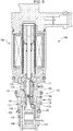
FIG. 1 is a front sectional view of a capacity control valve according to the present invention. -
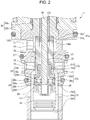
FIG. 2 is an enlarged view of part of a valve main body, a valve element, and a solenoid ofFIG. 1 showing the capacity control valve at the time of turning off the solenoid. -
FIG. 3 is an enlarged view of part of the valve main body, the valve element, and the solenoid ofFIG. 1 showing a control state of the capacity control valve. -
FIG. 4 is an enlarged view of part of the valve main body, the valve element, and the solenoid ofFIG. 1 showing a state of the capacity control valve at the time of liquid coolant discharge. -
FIG. 5 is a front sectional view showing a conventional capacity control valve. -
FIG. 6 shows a state of the conventional capacity control valve at the time of liquid coolant discharge. - Hereinafter, with reference to the drawings, a mode for carrying out the present invention will be described illustratively based on an embodiment. However, the dimensions, materials, shapes, relative positions, etc. of constituent parts described in this embodiment are not limited only to themselves unless otherwise described particularly explicitly.
- With reference to
FIGS. 1 to 4 , a capacity control valve according to the present invention will be described. InFIG. 1 , thereference sign 1 denotes a capacity control valve. Thecapacity control valve 1 is mainly formed by a valvemain body 10, avalve element 20, a pressure-sensitive body 24, and asolenoid 30. - Hereinafter, with reference to
FIGS. 1 and2 , respective constituent elements of thecapacity control valve 1 will be described. The valvemain body 10 is made of metal such as brass, iron, aluminum, stainless, or synthetic resin, etc. The valvemain body 10 is a cylindrical hollow member having a through hole which passes through in the axial direction. In sections of the through hole, afirst valve chamber 14, asecond valve chamber 15 adjacent to thefirst valve chamber 14, and athird valve chamber 16 adjacent to thesecond valve chamber 15 are continuously arranged. - A
second communication passage 12 is continuously provided in thesecond valve chamber 15. Thissecond communication passage 12 communicates with the inside of a discharge chamber (not shown) of a variable capacity compressor so that a fluid of discharge pressure Pd (second pressure according to the present invention) can flow in from thesecond valve chamber 15 to thethird valve chamber 16 by opening and closing thecapacity control valve 1. - A
third communication passage 13 is continuously provided in thethird valve chamber 16. Thethird communication passage 13 communicates with a control chamber (not shown) of the variable capacity compressor so that the fluid of discharge pressure Pd flowing in from thesecond valve chamber 15 to thethird valve chamber 16 by opening and closing thecapacity control valve 1 flows out to the control chamber (crank chamber) of the variable capacity compressor and a fluid of control chamber pressure Pc (third pressure according to the present invention) flowing into thethird valve chamber 16 flows out to a suction chamber of the variable capacity compressor via anintermediate communication passage 29 to be described later and through thefirst valve chamber 14. - Further, a
first communication passage 11 is continuously provided in thefirst valve chamber 14. Thisfirst communication passage 11 leads a fluid of suction pressure Ps (first pressure according to the present invention) from the suction chamber of the variable capacity compressor to the pressure-sensitive body 24 via theintermediate communication passage 29 to be described later, and controls the suction pressure of the compressor to a set value. - Between the
first valve chamber 14 and thesecond valve chamber 15, ahole portion 18 having a diameter smaller than a diameter of any of these chambers is continuously formed. Thishole portion 18 slides with alabyrinth 21f to be described later and forms a seal portion that seals a part between thefirst valve chamber 14 and thesecond valve chamber 15. Between thesecond valve chamber 15 and thethird valve chamber 16, avalve hole 17 having a diameter smaller than a diameter of any of these chambers is continuously provided. Amain valve seat 15a is formed around thevalve hole 17 on thesecond valve chamber 15 side. Thismain valve seat 15a is separated from and connected to amain valve portion 21c to be described later so as to control opening and closing of a Pd-Pc flow passage providing communication between thesecond communication passage 12 and thethird communication passage 13. - The pressure-
sensitive body 24 is arranged in thethird valve chamber 16. One end portion of a metal bellows 24a of this pressure-sensitive body 24 is combined to apartition adjusting portion 24f in a sealed state. This bellows 24a is made of phosphor bronze, stainless, etc. and a spring constant of the bellows is designed to be a predetermined value. An internal space of the pressure-sensitive body 24 is vacuum or the air exists in the internal space. Pressure acts on a valid pressure receiving area of thebellows 24a of this pressure-sensitive body 24 so that the pressure-sensitive body 24 is extended and contracted. Aflange portion 24d is arranged on the free end portion side of the pressure-sensitive body 24. By directly pressing thisflange portion 24d by a lockingportion 26 of asecond rod 36 to be described later, the pressure-sensitive body 24 is extended and contracted. That is, as described later, the pressure-sensitive body 24 is extended and contracted in accordance with the suction pressure Ps led to the pressure-sensitive body 24 via theintermediate communication passage 29, and also extended and contracted by pressing force of thesecond rod 36. - The
partition adjusting portion 24f of the pressure-sensitive body 24 is sealed, fitted, and fixed so as to close thethird valve chamber 16 of the valvemain body 10. By screwing thepartition adjusting portion 24f and fixing by a locking screw (not shown), it is possible to adjust axial movement of spring force of a compression spring arranged in parallel in thebellows 24a or thebellows 24a. - For example, two to six parts of each of the
first communication passage 11, thesecond communication passage 12, and thethird communication passage 13 pass through a peripheral surface of the valvemain body 10 at equal intervals. Further, attachment grooves for ○ rings are provided at three points while being separated in the axial direction on an outer peripheral surface of the valvemain body 10. ○ rings 47, 48, 49 that seal a part between the valvemain body 10 and an installment hole of a casing (not shown) fitted to the valvemain body 10 are attached to the attachment grooves. Flow passages of thefirst communication passage 11, thesecond communication passage 12, and thethird communication passage 13 are formed as independent flow passages. - Next, the
valve element 20 will be described. Thevalve element 20 is mainly formed by amain valve element 21 which is a cylindrical hollow member, and anadapter 23. First, themain valve element 21 will be described. Themain valve element 21 is a cylindrical hollow member, and thelabyrinth 21f is formed in a substantially center portion in the axial direction of an outer peripheral portion of the main valve element. Themain valve element 21 is inserted into the valvemain body 10, and thelabyrinth 21f slides on thehole portion 18 between thefirst valve chamber 14 side and thesecond valve chamber 15 side so as to form a seal portion that seals thefirst valve chamber 14 and thesecond valve chamber 15. Thereby, thefirst valve chamber 14 communicating with thefirst communication passage 11 and thesecond valve chamber 15 communicating with thesecond communication passage 12 are formed as independent valve chambers. - The
main valve element 21 is arranged on thefirst communication passage 11 side and on thesecond communication passage 12 side across thelabyrinth 21f. Themain valve portion 21c is formed in an end portion of themain valve element 21 arranged on thesecond communication passage 12 side. Themain valve portion 21c is separated from and connected to themain valve seat 15a so as to control opening and closing of thevalve hole 17 providing communication between thesecond communication passage 12 and thethird communication passage 13. Themain valve portion 21c and themain valve seat 15a form amain valve 27b. A situation where themain valve portion 21c and themain valve seat 15a are brought from a contact state into a separate state will be indicated as themain valve 27b is opened or themain valve portion 21c is opened. A situation where themain valve portion 21c and themain valve seat 15a are brought from a separate state into a contact state will be indicated as themain valve 27b is closed or themain valve portion 21c is closed. A shut-offvalve portion 21a is formed in an end portion of themain valve element 21 arranged in thefirst valve chamber 14. When thesolenoid 30 to be described later is turned off, the shut-offvalve portion 21a is brought into contact with anend portion 32c of a core 32 so as to shut off communication between theintermediate communication passage 29 and thefirst communication passage 11. The shut-offvalve portion 21a and theend portion 32c of the core 32 form a shut-offvalve 27a. The shut-offvalve portion 21a and themain valve portion 21c of thevalve element 20 perform opening and closing actions in the opposite directions to each other. A situation where the shut-offvalve portion 21a and theend portion 32c of the core 32 are brought from a contact state into a separate state will be indicated as the shut-offvalve 27a is opened or the shut-offvalve portion 21a is opened. A situation where the shut-offvalve portion 21a and theend portion 32c of the core 32 are brought from a separate state into a contact state will be indicated as the shut-offvalve 27a is closed or the shut-offvalve portion 21a is closed. - Next, the
adapter 23 forming thevalve element 20 will be described. Theadapter 23 is mainly formed by alarge diameter portion 23c formed to have a large diameter by a cylindrical hollow member, and atube portion 23e formed to have a diameter smaller than thelarge diameter portion 23c. Thetube portion 23e is fitted to an opening end portion on themain valve portion 21c side of themain valve element 21 so that thevalve element 20 is formed. Thereby, theintermediate communication passage 29 passing through in the axial direction is formed in the inside of themain valve element 21 and theadapter 23, that is, the inside of thevalve element 20. Anauxiliary valve portion 23d is formed in an end portion of thelarge diameter portion 23c of theadapter 23. Theauxiliary valve portion 23d is brought into contact with and separated from anauxiliary valve seat 26c of the lockingportion 26 of thesecond rod 36 so as to open and close theintermediate communication passage 29 providing communication between thefirst communication passage 11 and thethird communication passage 13. Theauxiliary valve portion 23d and theauxiliary valve seat 26c form anauxiliary valve 27c. A situation where theauxiliary valve portion 23d and theauxiliary valve seat 26c are brought from a contact state into a separate state will be indicated as theauxiliary valve 27c is opened or theauxiliary valve portion 23d is opened. A situation where theauxiliary valve portion 23d and theauxiliary valve seat 26c are brought from a separate state into a contact state will be indicated as theauxiliary valve 27c is closed or theauxiliary valve portion 23d is closed. - Next, the
solenoid 30 will be described. Thesolenoid 30 mainly includes afirst rod 136, thesecond rod 36, aplunger case 38, anelectromagnetic coil 31, the core 32 formed by acenter post 32a and abase member 32b, aplunger 35, aplate 34, and asolenoid case 33. Thefirst rod 136 and thesecond rod 36 are driven in accordance with electric currents supplied from the outside. Theplunger case 38 is a bottomed cylindrical hollow member whose one side is open. Theplunger 35 is arranged movably in the axial direction with respect to theplunger case 38 between theplunger case 38 and thecenter post 32a arranged inside theplunger case 38. Thecore 32 is fitted to the valvemain body 10 and arranged between theplunger 35 and the valvemain body 10. - An opening end portion of the
plunger case 38 is fixed to an inner peripheral portion of thebase member 32b of the core 32 in a sealed state, and thesolenoid case 33 is fixed to an outer peripheral portion of thebase member 32b in a sealed state. Theelectromagnetic coil 31 is arranged in a space surrounded by theplunger case 38, thebase member 32b of the core 32, and thesolenoid case 33 and not brought into contact with a coolant. Thus, it is possible to prevent a decrease in insulation resistance. - The
first rod 136 is a hollow axial member arranged in thecenter post 32a of thecore 32. Thefirst rod 136 has a clearance from a throughhole 32e of thecenter post 32a of the core 32 so as to be relatively moved with respect to thecore 32. Oneend portion 136a of thefirst rod 136 is pressed and driven by anend portion 36m of thesecond rod 36 fixed to theplunger 35 via aspring 137. Acommunication groove 136f is formed in an outer peripheral portion of theother end portion 136b of thefirst rod 136, and theend portion 136b and themain valve element 21 are fitted and fixed to each other. Since thecommunication groove 136f is formed in the outer peripheral portion of theend portion 136b of thefirst rod 136, even in a state where theend portion 136b and themain valve element 21 are fitted to each other, theintermediate communication passage 29 is not closed and a flow of the coolant is not inhibited. - The
second rod 36 is an axial member arranged in thefirst rod 136. Thesecond rod 36 has a clearance from a throughhole 136e of thefirst rod 136 so as to be relatively moved with respect to thecore 32 and thefirst rod 136. Oneend portion 36e of thesecond rod 36 is fixed to theplunger 35, and the lockingportion 26 is fitted and fixed to theother end portion 36h of thesecond rod 36. - The locking
portion 26 forming part of thesecond rod 36 will be described. The lockingportion 26 is a disc plate shaped member in which abase portion 26a is formed and brim portions are formed from thebase portion 26a on both sides in the axial direction. One of the brim portions functions as theauxiliary valve seat 26c to be separated from and connected to theauxiliary valve portion 23d of theadapter 23, and the other brim portion functions as apressing portion 26d to be separated from and connected to theflange portion 24d of the pressure-sensitive body 24 so as to extend and contract the pressure-sensitive body 24. Adistribution hole 26f through which the coolant is distributed is formed in thebase portion 26a of the lockingportion 26. The lockingportion 26 may be integrated with thesecond rod 36 or the lockingportion 26 may be fitted and fixed to thesecond rod 36 and integrally formed. - Between the
core 32 and theplunger 35, the spring 137 (first biasing member according to the present invention) that biases and separates theplunger 35 from thecore 32, and a spring 37 (second biasing member according to the present invention) are arranged. - The
spring 137 is arranged between theplunger 35 and thecore 32. Specifically, one end of thespring 137 is in contact with theend portion 136a of thefirst rod 136, the other end is in contact with theend portion 36m of thesecond rod 36 fixed to theplunger 35, thefirst rod 136 and theplunger 35 are biased in the direction in which the first rod and the plunger are separated from each other, and thevalve element 20 is biased in the valve closing direction of themain valve 27b. Thespring 137 is assembled between thefirst rod 136 and thesecond rod 36 in a state where the spring is compressed by a predetermined amount from natural length, that is, in a state where the spring has an initial set load. Thereby, thespring 137 is not deformed with drive force of thesolenoid 30 being not more than the initial set load, and thefirst rod 136 and thesecond rod 36 are integrally moved. Thespring 137 is deformed upon exceeding the initial set load, and thefirst rod 136 and thesecond rod 36 are relatively moved. The initial set load of thespring 137 is set to be larger than the drive force of thesolenoid 30 at the time of controlling thecapacity control valve 1. Thespring 137 may be arranged so that the one end is in contact with theend portion 136a of thefirst rod 136 and the other end is in contact with theplunger 35. - The
spring 37 is arranged between theplunger 35 and thecore 32. Specifically, one end of thespring 37 is in contact with an end portion of thecenter post 32a, the other end is in contact with an end portion of theplunger 35, and thecore 32 and theplunger 35 are biased in the direction in which the core and the plunger are separated from each other. An initial set load of thespring 37 is small, thespring 37 is deformed in proportion to the drive force of thesolenoid 30, and thesecond rod 36 is relatively moved with respect to the core 32 in accordance with the drive force of thesolenoid 30. - Actions of the
capacity control valve 1 having the configuration described above will be described. A flow passage running from thethird communication passage 13 to thefirst communication passage 11 through theintermediate communication passage 29 will be called as the "Pc-Ps flow passage" below. A flow passage running from thesecond communication passage 12 to thethird communication passage 13 through thevalve hole 17 will be called as the "Pd-Pc flow passage" below. - First, movement of the
first rod 136 and thesecond rod 36 and movement of the valve portions of thevalve element 20 will be described. First of all, based onFIGS. 1 and2 , the movement of thefirst rod 136 and thesecond rod 36 and the movement of the valve portions of thevalve element 20 in a non-energized state of thesolenoid 30 will be described. In a non-energized state, theplunger 35 is pushed upward by biasing force of the pressure-sensitive body 24 and biasing force of the spring 37 (FIG. 1 ), themain valve portion 21c of thevalve element 20 is fully opened, and the shut-offvalve portion 21a is fully closed. The lockingportion 26 of thesecond rod 36 is brought into contact with theadapter 23 and theauxiliary valve 27c is closed. - Next, based on
FIG. 3 , the movement of thefirst rod 136 and thesecond rod 36 and the movement of the valve portions of thevalve element 20 in a state where energization of thesolenoid 30 is started from a non-energized state and themain valve 27b is opened will be described. Since the initial set load of thespring 137 is set to be larger than the drive force of thesolenoid 30 at the time of controlling thecapacity control valve 1, in a state where themain valve 27b is opened, thefirst rod 136 and thesecond rod 36 are integrally moved in a state where relative positions are maintained. First, when energization of thesolenoid 30 is started from a non-energized state, thefirst rod 136 and thesecond rod 36 are integrally and gradually driven in the forward direction (direction in which thefirst rod 136 and thesecond rod 36 pop out from theend portion 32c of the core 32 to the outside). Thereby, the shut-offvalve portion 21a is separated from theend portion 32c of the core 32, the shut-offvalve 27a is opened from a fully closed state, and themain valve 27b is gradually narrowed down from a fully opened state. At the time of controlling thecapacity control valve 1, thevalve element 20 connected to thefirst rod 136 and thesecond rod 36 are integrally displaced. Thus, thecapacity control valve 1 can stably control an opening degree of themain valve 27b. - Further, when the
first rod 136 and thesecond rod 36 are driven in the forward direction, as shown inFIG. 4 , the shut-offvalve 27a is brought into a fully opened state, themain valve portion 21c is brought into contact with themain valve seat 15a, themain valve 27b is brought into a fully closed state, and the movement of thefirst rod 136 and thevalve element 20 is stopped. That is, when thesolenoid 30 is further driven in a state where thefirst rod 136 and thevalve element 20 are stopped, that is, in a state where themain valve 27b is fully closed, the drive force of thesolenoid 30 exceeds the initial set load of thespring 137, thespring 137 is deformed, and relative movement of thesecond rod 36 with respect to thefirst rod 136 is started. Thus, the lockingportion 26 of thesecond rod 36 is separated from theauxiliary valve seat 26c and theauxiliary valve 27c is opened. Further, when thesecond rod 36 is driven, thespring 137 is deformed, thepressing portion 26d of the lockingportion 26 presses theflange portion 24d, and the pressure-sensitive body 24 is contracted, so that it is possible to bring theauxiliary valve 27c into a fully opened state. When the pressure-sensitive body 24 is contracted by a predetermined amount, a projectedportion 24h of theflange portion 24d and a projected portion (not shown) provided in thepartition adjusting portion 24f are brought into contact with each other, deformation of the pressure-sensitive body 24 is stopped, and the movement of thesecond rod 36 is also stopped. - The movement of the
first rod 136 and thesecond rod 36 and the movement of the valve portions of thevalve element 20 are described above. Next, actions of thecapacity control valve 1 and the variable capacity compressor will be described based onFIG. 3 . First, a control state of thecapacity control valve 1 will be described. The control state is a state where theauxiliary valve 27c is in a closed state, the opening degree of themain valve 27b is set to an opening degree determined in advance, and pressure of the suction chamber of the variable capacity compressor is controlled to be a set value Pset. In this state, the fluid of the suction pressure Ps from the suction chamber of the variable capacity compressor passes from thefirst communication passage 11, thefirst valve chamber 14, and thecommunication groove 136f through to theintermediate communication passage 29, flows to aninternal space 28 surrounded by the lockingportion 26 of thesecond rod 36 and the pressure-sensitive body 24, and acts on the pressure-sensitive body 24. As a result, themain valve portion 21c is stopped at a position where force in the valve opening direction by thespring 37, force by thesolenoid 30, and force by the pressure-sensitive body 24 to be extended and contracted in accordance with the suction pressure Ps are balanced, and the pressure of the suction chamber of the variable capacity compressor is controlled to be the set value Pset. However, even when the opening degree of themain valve 27b is set to the opening degree determined in advance, there is sometimes a case where the pressure Ps of the suction chamber is varied with respect to the set value Pset due to disturbance, etc. For example, when the pressure Ps of the suction chamber is increased to be more than the set value Pset due to disturbance, etc., the pressure-sensitive body 24 is contracted and the opening degree of themain valve 27b is decreased. Thereby, since the Pd-Pc flow passage is narrowed down, an amount of the fluid of the discharge pressure Pd flowing in from the discharge chamber to the crank chamber is reduced and pressure of the crank chamber is lowered. As a result, a tilting angle of a swash plate of the compressor is increased, a discharge capacity of the compressor is increased, and discharge pressure is lowered. On the contrary, when the pressure Ps of the suction chamber is decreased to be lower than the set value Pset, the pressure-sensitive body 24 is extended and the opening degree of themain valve 27b is increased. Thereby, since the Pd-Pc flow passage is increased, the amount of the fluid of the discharge pressure Pd flowing in from the discharge chamber to the crank chamber is increased and the pressure of the crank chamber is increased. As a result, the tilting angle of the swash plate of the compressor is decreased, the discharge capacity of the compressor is reduced, and the discharge pressure is increased. In this way, by thecapacity control valve 1, it is possible to control the pressure of the suction chamber of the variable capacity compressor to be the set value Pset. - Next, a liquid coolant discharge state of the
capacity control valve 1 will be described based onFIG. 4 . After the compressor is stopped for a long time, a liquid coolant (made by cooling and liquefying a coolant during abandonment) is accumulated in the crank chamber. Thus, in order to ensure predetermined discharge pressure and a predetermined discharge flow rate after start-up of the compressor, there is a need for discharging the liquid coolant as soon as possible. At the time of liquid coolant discharge, since pressure of thethird valve chamber 16 communicating with the crank chamber and the suction pressure Ps are high pressure, and the pressure-sensitive body 24 is contracted, theauxiliary valve 27c is opened. By opening theauxiliary valve 27c, it is possible to discharge the liquid coolant from the crank chamber to the suction chamber via the Pc-Ps flow passage. However, as discharge of the liquid coolant progresses, the pressure of the crank chamber and the suction pressure Ps are lowered. Thus, the opening degree of theauxiliary valve 27c is gradually decreased. Therefore, it takes time to completely discharge the liquid coolant. Meanwhile, in thecapacity control valve 1 of the present invention, by driving thesolenoid 30 in the forward direction and pressing the pressure-sensitive body 24 by the lockingportion 26 of thesecond rod 36, it is possible to forcibly maintain theauxiliary valve 27c in a fully opened state. Thus, an opening degree of theauxiliary valve portion 23d is not changed from start of the liquid coolant discharge to completion of the liquid coolant discharge, and it is possible to discharge the liquid coolant from the crank chamber to the suction chamber via the Pc-Ps flow passage for a short time. - Conventionally, at the time of a liquid coolant discharging operation, focus is placed only on how quickly discharge of the liquid coolant is completed. Thus, there is sometimes a case where an engine load becomes excessive during the liquid coolant discharging operation. With the
capacity control valve 1 according to the present invention, even at the time of the liquid coolant discharge, it is possible to rapidly drive thevalve element 20. At the time of the liquid coolant discharge, actions of thecapacity control valve 1 when the engine load is reduced will be described. - In a case where the engine load is rapidly reduced at the time of the liquid coolant discharge, the
solenoid 30 is turned off and magnetic attracting force Fsol between the core 32 and theplunger 35 is operated to be zero. Since settings is made to cancel upward pressure and downward pressure acting on thevalve element 20 at the time of the liquid coolant discharge, regarding major force acting on thevalve element 20 at the time of the liquid coolant discharge, the biasing force of thespring 37 acting in the valve opening direction of themain valve 27b, and the total force of biasing force of thespring 137 acting in the valve closing direction of themain valve 27b and the magnetic attracting force Fsol of thesolenoid 30 are balanced. When the magnetic attracting force Fsol of thesolenoid 30 becomes zero, the biasing force of thespring 37 acting in the valve opening direction of themain valve 27b becomes dominant, and thesecond rod 36 is moved upward. As a result, thesecond rod 36 is rapidly pushed up, the lockingportion 26 is brought into contact with theadapter 23, thevalve element 20 is driven in the valve opening direction of themain valve 27b, and themain valve 27b is rapidly fully opened. When themain valve 27b is fully opened, a coolant amount flowing from the discharge chamber of the compressor to the crank chamber through the Pd-Pc flow passage is increased, the pressure Pc in the crank chamber is increased, and the compressor is operated by the minimum capacity. In this way, as the time of the liquid coolant discharge, even in a state where theauxiliary valve 27c is in an opened state and no force acts on thevalve element 20 from the pressure-sensitive body 24, it is possible to reduce the load of the compressor and hence it is possible to reduce the engine load even at the time of the liquid coolant discharge. - In the control state where the pressure of the suction chamber of the compressor is controlled to be the set value Pset by the
capacity control valve 1, and in a case where the load of the engine is to be reduced, by bringing thesolenoid 30 into a non-energized state similarly to the above description, themain valve 27b is brought into a fully opened state, the coolant amount of the Pd pressure flowing from the discharge chamber of the compressor to the crank chamber through the Pd-Pc flow passage is increased, and the compressor is operated by the minimum capacity, so that it is possible to perform an operation with which the load of the engine is reduced. - In this way, the initial set load of the
spring 137 is set to be larger than the drive force of thesolenoid 30 at the time of controlling thecapacity control valve 1. Thus, in a state where themain valve 27b is opened, thespring 137 is hardly deformed. Therefore, thevalve element 20 connected to thefirst rod 136 and thesecond rod 36 are integrally displaced. Thus, thecapacity control valve 1 can stably control the opening degree of themain valve 27b. As the time of the liquid coolant discharge of thecapacity control valve 1, in a case where the drive force of thesolenoid 30 exceeds the initial set load of thespring 137, thespring 137 is deformed, thesecond rod 36 is relatively moved with respect to thefirst rod 136, and the lockingportion 26 of thesecond rod 36 is separated from theauxiliary valve seat 26c, so that it is possible to forcibly open theauxiliary valve 27c. Thereby, at the time of the liquid coolant discharge, it is possible to maintain theauxiliary valve 27c in a fully opened state irrespective of the pressure of thethird valve chamber 16 and the suction pressure Ps. Thus, it is possible to discharge the liquid coolant from the crank chamber to the suction chamber via the Pc-Ps flow passage for a short time. - The embodiment of the present invention is described with the drawings above. Specific configurations are not limited to the embodiment but the present invention also includes changes and additions within the range not departing from the gist of the present invention.
- In the above embodiment, the first pressure of the
first valve chamber 14 is the suction pressure Ps of the variable capacity compressor, the second pressure of thesecond valve chamber 15 is the discharge pressure Pd of the variable capacity compressor, and the third pressure of thethird valve chamber 16 is the pressure Pc of the crank chamber of the variable capacity compressor. However, the present invention is not limited to this but with the first pressure of thefirst valve chamber 14 being the pressure Pc of the crank chamber of the variable capacity compressor, the second pressure of thesecond valve chamber 15 being the discharge pressure Pd of the variable capacity compressor, and the third pressure of thethird valve chamber 16 being the suction pressure Ps of the variable capacity compressor, it is possible to respond to various variable capacity compressors. -
- 1 capacity control valve
- 10 valve main body
- 11 first communication passage
- 12 second communication passage
- 13 third communication passage
- 14 first valve chamber
- 15 second valve chamber
- 15a main valve seat
- 16 third valve chamber
- 17 valve hole
- 20 valve element
- 21 main valve element
- 21a shut-off valve portion
- 21c main valve portion
- 23 adaptor
- 23d auxiliary valve portion
- 24 pressure-sensitive body
- 24a bellows
- 24d flange portion
- 26 locking portion
- 26c auxiliary valve seat
- 26d pressing portion
- 27a shut-off valve
- 27b main valve
- 27c auxiliary valve
- 29 intermediate communication passage
- 30 solenoid
- 31 electromagnetic coil
- 32 core
- 35 plunger
- 36 second rod
- 136 first rod
- 37 spring (second biasing member)
- 137 spring (first biasing member)
- Fsol magnetic attracting force
- Ps suction pressure (first pressure) (third pressure)
- Pd discharge pressure
- Pc control chamber pressure (third pressure) (first pressure)
- Pset suction pressure set value
Claims (7)
- A capacity control valve that controls a flow rate or pressure of a variable capacity compressor in accordance with a valve opening degree of a valve portion, the capacity control valve being characterized by comprising:a valve main body having a first communication passage through which a fluid of first pressure passes, a second communication passage arranged adjacent to the first communication passage, the second communication passage through which a fluid of second pressure passes, a third communication passage through which a fluid of third pressure passes, and a main valve seat arranged in a valve hole which provides communication between the second communication passage and the third communication passage;a valve element having an intermediate communication passage providing communication between the first communication passage and the third communication passage, a main valve portion to be separated from and connected to the main valve seat so as to open and close the valve hole, and an auxiliary valve portion arranged in the intermediate communication passage; anda solenoid having a plunger that drives a first rod and a second rod, characterized in thatthe first rod opens and closes the main valve portion, and the second rod opens and closes the auxiliary valve portion.
- The capacity control valve according to claim 1, characterized in that one end of the first rod is driven by the plunger via a first biasing member, and the other end is connected to the valve element.
- The capacity control valve according to claim 1 or 2, characterized in that one end of the second rod is connected to the plunger, and the other end is connected to an auxiliary valve seat to be separated from and connected to the auxiliary valve portion.
- The capacity control valve according to any one of claims 1 to 3, characterized in that the solenoid further includes a core arranged between the plunger and the valve main body, an electromagnetic coil, and a second biasing member arranged between the plunger and the core.
- The capacity control valve according to any one of claims 1 to 4, characterized in that the first pressure is suction pressure of the variable capacity compressor, the second pressure is discharge pressure of the variable capacity compressor, and the third pressure is pressure of a crank chamber of the variable capacity compressor.
- The capacity control valve according to any one of claims 1 to 4, characterized in that the first pressure is pressure of a crank chamber of the variable capacity compressor, the second pressure is discharge pressure of the variable capacity compressor, and the third pressure is suction pressure of the variable capacity compressor.
- A method for controlling a capacity control valve, characterized by comprising the step of:by using the capacity control valve according to any one of claims 1 to 6,making the main valve portion from a closed state to an opened state when the auxiliary valve portion is in an opened state.
Applications Claiming Priority (2)
| Application Number | Priority Date | Filing Date | Title |
|---|---|---|---|
| JP2018008481 | 2018-01-22 | ||
| PCT/JP2019/001569 WO2019142930A1 (en) | 2018-01-22 | 2019-01-21 | Capacity control valve and control method of capacity control valve |
Publications (3)
| Publication Number | Publication Date |
|---|---|
| EP3744977A1 true EP3744977A1 (en) | 2020-12-02 |
| EP3744977A4 EP3744977A4 (en) | 2021-09-01 |
| EP3744977B1 EP3744977B1 (en) | 2023-05-24 |
Family
ID=67302317
Family Applications (1)
| Application Number | Title | Priority Date | Filing Date |
|---|---|---|---|
| EP19741397.4A Active EP3744977B1 (en) | 2018-01-22 | 2019-01-21 | Capacity control valve and control method of capacity control valve |
Country Status (5)
| Country | Link |
|---|---|
| US (1) | US11326707B2 (en) |
| EP (1) | EP3744977B1 (en) |
| JP (1) | JP7139075B2 (en) |
| CN (1) | CN111601970B (en) |
| WO (1) | WO2019142930A1 (en) |
Family Cites Families (14)
| Publication number | Priority date | Publication date | Assignee | Title |
|---|---|---|---|---|
| JP3726759B2 (en) * | 2002-02-18 | 2005-12-14 | 株式会社豊田自動織機 | Control device for variable capacity compressor |
| JP2005307817A (en) | 2004-04-20 | 2005-11-04 | Toyota Industries Corp | Capacity controller for variable displacement compressor |
| JP2006194175A (en) | 2005-01-14 | 2006-07-27 | Tgk Co Ltd | Control valve for variable displacement compressor |
| CN101410620B (en) * | 2006-03-15 | 2011-03-23 | 伊格尔工业股份有限公司 | Capacity control valve |
| JP5878703B2 (en) | 2010-09-06 | 2016-03-08 | 株式会社不二工機 | Control valve for variable displacement compressor |
| JP6064132B2 (en) | 2012-10-09 | 2017-01-25 | 株式会社テージーケー | Compound valve |
| JP6064131B2 (en) * | 2012-10-17 | 2017-01-25 | 株式会社テージーケー | Control valve for variable capacity compressor |
| JP6064123B2 (en) | 2012-11-01 | 2017-01-25 | 株式会社テージーケー | Control valve |
| JP6149239B2 (en) * | 2013-06-28 | 2017-06-21 | 株式会社テージーケー | Control valve for variable capacity compressor |
| JP6340661B2 (en) * | 2014-02-27 | 2018-06-13 | 株式会社テージーケー | Control valve for variable capacity compressor |
| JP6500183B2 (en) | 2015-04-02 | 2019-04-17 | 株式会社テージーケー | Control valve for variable displacement compressor |
| JP2017089832A (en) | 2015-11-13 | 2017-05-25 | 株式会社テージーケー | solenoid valve |
| JP6647156B2 (en) * | 2016-06-28 | 2020-02-14 | 株式会社不二工機 | Control valve for variable displacement compressor |
| JP7086490B2 (en) * | 2017-12-08 | 2022-06-20 | イーグル工業株式会社 | Capacity control valve and capacity control valve control method |
-
2019
- 2019-01-21 CN CN201980008540.5A patent/CN111601970B/en active Active
- 2019-01-21 WO PCT/JP2019/001569 patent/WO2019142930A1/en not_active Ceased
- 2019-01-21 US US16/961,620 patent/US11326707B2/en active Active
- 2019-01-21 JP JP2019566537A patent/JP7139075B2/en active Active
- 2019-01-21 EP EP19741397.4A patent/EP3744977B1/en active Active
Also Published As
| Publication number | Publication date |
|---|---|
| CN111601970A (en) | 2020-08-28 |
| WO2019142930A1 (en) | 2019-07-25 |
| EP3744977B1 (en) | 2023-05-24 |
| US11326707B2 (en) | 2022-05-10 |
| CN111601970B (en) | 2022-05-17 |
| JPWO2019142930A1 (en) | 2021-01-07 |
| JP7139075B2 (en) | 2022-09-20 |
| US20210190228A1 (en) | 2021-06-24 |
| EP3744977A4 (en) | 2021-09-01 |
Similar Documents
| Publication | Publication Date | Title |
|---|---|---|
| EP3734067B1 (en) | Capacity control valve | |
| US11486376B2 (en) | Capacity control valve and method for controlling same | |
| US11795928B2 (en) | Capacity control valve and capacity control valve control method | |
| JP7083844B2 (en) | Capacity control valve and capacity control valve control method | |
| US11542929B2 (en) | Capacity control valve and method for controlling capacity control valve | |
| EP3744976B1 (en) | Capacity control valve | |
| US11519399B2 (en) | Capacity control valve and method for controlling same | |
| EP3744977B1 (en) | Capacity control valve and control method of capacity control valve |
Legal Events
| Date | Code | Title | Description |
|---|---|---|---|
| STAA | Information on the status of an ep patent application or granted ep patent |
Free format text: STATUS: THE INTERNATIONAL PUBLICATION HAS BEEN MADE |
|
| PUAI | Public reference made under article 153(3) epc to a published international application that has entered the european phase |
Free format text: ORIGINAL CODE: 0009012 |
|
| STAA | Information on the status of an ep patent application or granted ep patent |
Free format text: STATUS: REQUEST FOR EXAMINATION WAS MADE |
|
| 17P | Request for examination filed |
Effective date: 20200720 |
|
| AK | Designated contracting states |
Kind code of ref document: A1 Designated state(s): AL AT BE BG CH CY CZ DE DK EE ES FI FR GB GR HR HU IE IS IT LI LT LU LV MC MK MT NL NO PL PT RO RS SE SI SK SM TR |
|
| AX | Request for extension of the european patent |
Extension state: BA ME |
|
| DAV | Request for validation of the european patent (deleted) | ||
| DAX | Request for extension of the european patent (deleted) | ||
| A4 | Supplementary search report drawn up and despatched |
Effective date: 20210730 |
|
| RIC1 | Information provided on ipc code assigned before grant |
Ipc: F04B 27/18 20060101AFI20210726BHEP Ipc: F16K 1/44 20060101ALI20210726BHEP Ipc: F16K 31/06 20060101ALI20210726BHEP |
|
| GRAP | Despatch of communication of intention to grant a patent |
Free format text: ORIGINAL CODE: EPIDOSNIGR1 |
|
| STAA | Information on the status of an ep patent application or granted ep patent |
Free format text: STATUS: GRANT OF PATENT IS INTENDED |
|
| INTG | Intention to grant announced |
Effective date: 20221212 |
|
| GRAS | Grant fee paid |
Free format text: ORIGINAL CODE: EPIDOSNIGR3 |
|
| GRAA | (expected) grant |
Free format text: ORIGINAL CODE: 0009210 |
|
| STAA | Information on the status of an ep patent application or granted ep patent |
Free format text: STATUS: THE PATENT HAS BEEN GRANTED |
|
| AK | Designated contracting states |
Kind code of ref document: B1 Designated state(s): AL AT BE BG CH CY CZ DE DK EE ES FI FR GB GR HR HU IE IS IT LI LT LU LV MC MK MT NL NO PL PT RO RS SE SI SK SM TR |
|
| REG | Reference to a national code |
Ref country code: GB Ref legal event code: FG4D |
|
| REG | Reference to a national code |
Ref country code: CH Ref legal event code: EP |
|
| REG | Reference to a national code |
Ref country code: DE Ref legal event code: R096 Ref document number: 602019029265 Country of ref document: DE |
|
| REG | Reference to a national code |
Ref country code: AT Ref legal event code: REF Ref document number: 1569628 Country of ref document: AT Kind code of ref document: T Effective date: 20230615 |
|
| REG | Reference to a national code |
Ref country code: IE Ref legal event code: FG4D |
|
| REG | Reference to a national code |
Ref country code: LT Ref legal event code: MG9D |
|
| REG | Reference to a national code |
Ref country code: NL Ref legal event code: MP Effective date: 20230524 |
|
| REG | Reference to a national code |
Ref country code: AT Ref legal event code: MK05 Ref document number: 1569628 Country of ref document: AT Kind code of ref document: T Effective date: 20230524 |
|
| PG25 | Lapsed in a contracting state [announced via postgrant information from national office to epo] |
Ref country code: SE Free format text: LAPSE BECAUSE OF FAILURE TO SUBMIT A TRANSLATION OF THE DESCRIPTION OR TO PAY THE FEE WITHIN THE PRESCRIBED TIME-LIMIT Effective date: 20230524 Ref country code: PT Free format text: LAPSE BECAUSE OF FAILURE TO SUBMIT A TRANSLATION OF THE DESCRIPTION OR TO PAY THE FEE WITHIN THE PRESCRIBED TIME-LIMIT Effective date: 20230925 Ref country code: NO Free format text: LAPSE BECAUSE OF FAILURE TO SUBMIT A TRANSLATION OF THE DESCRIPTION OR TO PAY THE FEE WITHIN THE PRESCRIBED TIME-LIMIT Effective date: 20230824 Ref country code: NL Free format text: LAPSE BECAUSE OF FAILURE TO SUBMIT A TRANSLATION OF THE DESCRIPTION OR TO PAY THE FEE WITHIN THE PRESCRIBED TIME-LIMIT Effective date: 20230524 Ref country code: ES Free format text: LAPSE BECAUSE OF FAILURE TO SUBMIT A TRANSLATION OF THE DESCRIPTION OR TO PAY THE FEE WITHIN THE PRESCRIBED TIME-LIMIT Effective date: 20230524 Ref country code: AT Free format text: LAPSE BECAUSE OF FAILURE TO SUBMIT A TRANSLATION OF THE DESCRIPTION OR TO PAY THE FEE WITHIN THE PRESCRIBED TIME-LIMIT Effective date: 20230524 |
|
| PG25 | Lapsed in a contracting state [announced via postgrant information from national office to epo] |
Ref country code: RS Free format text: LAPSE BECAUSE OF FAILURE TO SUBMIT A TRANSLATION OF THE DESCRIPTION OR TO PAY THE FEE WITHIN THE PRESCRIBED TIME-LIMIT Effective date: 20230524 Ref country code: PL Free format text: LAPSE BECAUSE OF FAILURE TO SUBMIT A TRANSLATION OF THE DESCRIPTION OR TO PAY THE FEE WITHIN THE PRESCRIBED TIME-LIMIT Effective date: 20230524 Ref country code: LV Free format text: LAPSE BECAUSE OF FAILURE TO SUBMIT A TRANSLATION OF THE DESCRIPTION OR TO PAY THE FEE WITHIN THE PRESCRIBED TIME-LIMIT Effective date: 20230524 Ref country code: LT Free format text: LAPSE BECAUSE OF FAILURE TO SUBMIT A TRANSLATION OF THE DESCRIPTION OR TO PAY THE FEE WITHIN THE PRESCRIBED TIME-LIMIT Effective date: 20230524 Ref country code: IS Free format text: LAPSE BECAUSE OF FAILURE TO SUBMIT A TRANSLATION OF THE DESCRIPTION OR TO PAY THE FEE WITHIN THE PRESCRIBED TIME-LIMIT Effective date: 20230924 Ref country code: HR Free format text: LAPSE BECAUSE OF FAILURE TO SUBMIT A TRANSLATION OF THE DESCRIPTION OR TO PAY THE FEE WITHIN THE PRESCRIBED TIME-LIMIT Effective date: 20230524 Ref country code: GR Free format text: LAPSE BECAUSE OF FAILURE TO SUBMIT A TRANSLATION OF THE DESCRIPTION OR TO PAY THE FEE WITHIN THE PRESCRIBED TIME-LIMIT Effective date: 20230825 |
|
| PG25 | Lapsed in a contracting state [announced via postgrant information from national office to epo] |
Ref country code: FI Free format text: LAPSE BECAUSE OF FAILURE TO SUBMIT A TRANSLATION OF THE DESCRIPTION OR TO PAY THE FEE WITHIN THE PRESCRIBED TIME-LIMIT Effective date: 20230524 |
|
| PG25 | Lapsed in a contracting state [announced via postgrant information from national office to epo] |
Ref country code: SK Free format text: LAPSE BECAUSE OF FAILURE TO SUBMIT A TRANSLATION OF THE DESCRIPTION OR TO PAY THE FEE WITHIN THE PRESCRIBED TIME-LIMIT Effective date: 20230524 |
|
| PG25 | Lapsed in a contracting state [announced via postgrant information from national office to epo] |
Ref country code: SM Free format text: LAPSE BECAUSE OF FAILURE TO SUBMIT A TRANSLATION OF THE DESCRIPTION OR TO PAY THE FEE WITHIN THE PRESCRIBED TIME-LIMIT Effective date: 20230524 Ref country code: SK Free format text: LAPSE BECAUSE OF FAILURE TO SUBMIT A TRANSLATION OF THE DESCRIPTION OR TO PAY THE FEE WITHIN THE PRESCRIBED TIME-LIMIT Effective date: 20230524 Ref country code: RO Free format text: LAPSE BECAUSE OF FAILURE TO SUBMIT A TRANSLATION OF THE DESCRIPTION OR TO PAY THE FEE WITHIN THE PRESCRIBED TIME-LIMIT Effective date: 20230524 Ref country code: EE Free format text: LAPSE BECAUSE OF FAILURE TO SUBMIT A TRANSLATION OF THE DESCRIPTION OR TO PAY THE FEE WITHIN THE PRESCRIBED TIME-LIMIT Effective date: 20230524 Ref country code: DK Free format text: LAPSE BECAUSE OF FAILURE TO SUBMIT A TRANSLATION OF THE DESCRIPTION OR TO PAY THE FEE WITHIN THE PRESCRIBED TIME-LIMIT Effective date: 20230524 Ref country code: CZ Free format text: LAPSE BECAUSE OF FAILURE TO SUBMIT A TRANSLATION OF THE DESCRIPTION OR TO PAY THE FEE WITHIN THE PRESCRIBED TIME-LIMIT Effective date: 20230524 |
|
| REG | Reference to a national code |
Ref country code: DE Ref legal event code: R097 Ref document number: 602019029265 Country of ref document: DE |
|
| PLBE | No opposition filed within time limit |
Free format text: ORIGINAL CODE: 0009261 |
|
| STAA | Information on the status of an ep patent application or granted ep patent |
Free format text: STATUS: NO OPPOSITION FILED WITHIN TIME LIMIT |
|
| 26N | No opposition filed |
Effective date: 20240227 |
|
| PG25 | Lapsed in a contracting state [announced via postgrant information from national office to epo] |
Ref country code: SI Free format text: LAPSE BECAUSE OF FAILURE TO SUBMIT A TRANSLATION OF THE DESCRIPTION OR TO PAY THE FEE WITHIN THE PRESCRIBED TIME-LIMIT Effective date: 20230524 |
|
| PG25 | Lapsed in a contracting state [announced via postgrant information from national office to epo] |
Ref country code: SI Free format text: LAPSE BECAUSE OF FAILURE TO SUBMIT A TRANSLATION OF THE DESCRIPTION OR TO PAY THE FEE WITHIN THE PRESCRIBED TIME-LIMIT Effective date: 20230524 Ref country code: IT Free format text: LAPSE BECAUSE OF FAILURE TO SUBMIT A TRANSLATION OF THE DESCRIPTION OR TO PAY THE FEE WITHIN THE PRESCRIBED TIME-LIMIT Effective date: 20230524 |
|
| PG25 | Lapsed in a contracting state [announced via postgrant information from national office to epo] |
Ref country code: MC Free format text: LAPSE BECAUSE OF FAILURE TO SUBMIT A TRANSLATION OF THE DESCRIPTION OR TO PAY THE FEE WITHIN THE PRESCRIBED TIME-LIMIT Effective date: 20230524 |
|
| PG25 | Lapsed in a contracting state [announced via postgrant information from national office to epo] |
Ref country code: MC Free format text: LAPSE BECAUSE OF FAILURE TO SUBMIT A TRANSLATION OF THE DESCRIPTION OR TO PAY THE FEE WITHIN THE PRESCRIBED TIME-LIMIT Effective date: 20230524 |
|
| REG | Reference to a national code |
Ref country code: CH Ref legal event code: PL |
|
| PG25 | Lapsed in a contracting state [announced via postgrant information from national office to epo] |
Ref country code: LU Free format text: LAPSE BECAUSE OF NON-PAYMENT OF DUE FEES Effective date: 20240121 |
|
| GBPC | Gb: european patent ceased through non-payment of renewal fee |
Effective date: 20240121 |
|
| PG25 | Lapsed in a contracting state [announced via postgrant information from national office to epo] |
Ref country code: LU Free format text: LAPSE BECAUSE OF NON-PAYMENT OF DUE FEES Effective date: 20240121 |
|
| PG25 | Lapsed in a contracting state [announced via postgrant information from national office to epo] |
Ref country code: GB Free format text: LAPSE BECAUSE OF NON-PAYMENT OF DUE FEES Effective date: 20240121 |
|
| PG25 | Lapsed in a contracting state [announced via postgrant information from national office to epo] |
Ref country code: BE Free format text: LAPSE BECAUSE OF NON-PAYMENT OF DUE FEES Effective date: 20240131 |
|
| PG25 | Lapsed in a contracting state [announced via postgrant information from national office to epo] |
Ref country code: FR Free format text: LAPSE BECAUSE OF NON-PAYMENT OF DUE FEES Effective date: 20240131 |
|
| PG25 | Lapsed in a contracting state [announced via postgrant information from national office to epo] |
Ref country code: CH Free format text: LAPSE BECAUSE OF NON-PAYMENT OF DUE FEES Effective date: 20240131 |
|
| PG25 | Lapsed in a contracting state [announced via postgrant information from national office to epo] |
Ref country code: GB Free format text: LAPSE BECAUSE OF NON-PAYMENT OF DUE FEES Effective date: 20240121 Ref country code: FR Free format text: LAPSE BECAUSE OF NON-PAYMENT OF DUE FEES Effective date: 20240131 Ref country code: CH Free format text: LAPSE BECAUSE OF NON-PAYMENT OF DUE FEES Effective date: 20240131 Ref country code: BE Free format text: LAPSE BECAUSE OF NON-PAYMENT OF DUE FEES Effective date: 20240131 |
|
| REG | Reference to a national code |
Ref country code: BE Ref legal event code: MM Effective date: 20240131 |
|
| PG25 | Lapsed in a contracting state [announced via postgrant information from national office to epo] |
Ref country code: BG Free format text: LAPSE BECAUSE OF FAILURE TO SUBMIT A TRANSLATION OF THE DESCRIPTION OR TO PAY THE FEE WITHIN THE PRESCRIBED TIME-LIMIT Effective date: 20230524 |
|
| PG25 | Lapsed in a contracting state [announced via postgrant information from national office to epo] |
Ref country code: BG Free format text: LAPSE BECAUSE OF FAILURE TO SUBMIT A TRANSLATION OF THE DESCRIPTION OR TO PAY THE FEE WITHIN THE PRESCRIBED TIME-LIMIT Effective date: 20230524 |
|
| PG25 | Lapsed in a contracting state [announced via postgrant information from national office to epo] |
Ref country code: IE Free format text: LAPSE BECAUSE OF NON-PAYMENT OF DUE FEES Effective date: 20240121 |
|
| PG25 | Lapsed in a contracting state [announced via postgrant information from national office to epo] |
Ref country code: IE Free format text: LAPSE BECAUSE OF NON-PAYMENT OF DUE FEES Effective date: 20240121 |
|
| PG25 | Lapsed in a contracting state [announced via postgrant information from national office to epo] |
Ref country code: CY Free format text: LAPSE BECAUSE OF FAILURE TO SUBMIT A TRANSLATION OF THE DESCRIPTION OR TO PAY THE FEE WITHIN THE PRESCRIBED TIME-LIMIT; INVALID AB INITIO Effective date: 20190121 |
|
| PG25 | Lapsed in a contracting state [announced via postgrant information from national office to epo] |
Ref country code: HU Free format text: LAPSE BECAUSE OF FAILURE TO SUBMIT A TRANSLATION OF THE DESCRIPTION OR TO PAY THE FEE WITHIN THE PRESCRIBED TIME-LIMIT; INVALID AB INITIO Effective date: 20190121 |
|
| PG25 | Lapsed in a contracting state [announced via postgrant information from national office to epo] |
Ref country code: TR Free format text: LAPSE BECAUSE OF FAILURE TO SUBMIT A TRANSLATION OF THE DESCRIPTION OR TO PAY THE FEE WITHIN THE PRESCRIBED TIME-LIMIT Effective date: 20230524 |
|
| PGFP | Annual fee paid to national office [announced via postgrant information from national office to epo] |
Ref country code: DE Payment date: 20251203 Year of fee payment: 8 |