EP3744972A1 - Rotor for a wind turbine and wind turbine - Google Patents
Rotor for a wind turbine and wind turbine Download PDFInfo
- Publication number
- EP3744972A1 EP3744972A1 EP19176665.8A EP19176665A EP3744972A1 EP 3744972 A1 EP3744972 A1 EP 3744972A1 EP 19176665 A EP19176665 A EP 19176665A EP 3744972 A1 EP3744972 A1 EP 3744972A1
- Authority
- EP
- European Patent Office
- Prior art keywords
- blade
- hub
- arc portion
- arc
- metal arcs
- Prior art date
- Legal status (The legal status is an assumption and is not a legal conclusion. Google has not performed a legal analysis and makes no representation as to the accuracy of the status listed.)
- Granted
Links
Images



Classifications
-
- F—MECHANICAL ENGINEERING; LIGHTING; HEATING; WEAPONS; BLASTING
- F03—MACHINES OR ENGINES FOR LIQUIDS; WIND, SPRING, OR WEIGHT MOTORS; PRODUCING MECHANICAL POWER OR A REACTIVE PROPULSIVE THRUST, NOT OTHERWISE PROVIDED FOR
- F03D—WIND MOTORS
- F03D80/00—Details, components or accessories not provided for in groups F03D1/00 - F03D17/00
- F03D80/30—Lightning protection
-
- F—MECHANICAL ENGINEERING; LIGHTING; HEATING; WEAPONS; BLASTING
- F03—MACHINES OR ENGINES FOR LIQUIDS; WIND, SPRING, OR WEIGHT MOTORS; PRODUCING MECHANICAL POWER OR A REACTIVE PROPULSIVE THRUST, NOT OTHERWISE PROVIDED FOR
- F03D—WIND MOTORS
- F03D1/00—Wind motors with rotation axis substantially parallel to the air flow entering the rotor
- F03D1/06—Rotors
- F03D1/065—Rotors characterised by their construction elements
- F03D1/0658—Arrangements for fixing wind-engaging parts to a hub
-
- F—MECHANICAL ENGINEERING; LIGHTING; HEATING; WEAPONS; BLASTING
- F03—MACHINES OR ENGINES FOR LIQUIDS; WIND, SPRING, OR WEIGHT MOTORS; PRODUCING MECHANICAL POWER OR A REACTIVE PROPULSIVE THRUST, NOT OTHERWISE PROVIDED FOR
- F03D—WIND MOTORS
- F03D1/00—Wind motors with rotation axis substantially parallel to the air flow entering the rotor
- F03D1/06—Rotors
- F03D1/065—Rotors characterised by their construction elements
- F03D1/0675—Rotors characterised by their construction elements of the blades
-
- F—MECHANICAL ENGINEERING; LIGHTING; HEATING; WEAPONS; BLASTING
- F03—MACHINES OR ENGINES FOR LIQUIDS; WIND, SPRING, OR WEIGHT MOTORS; PRODUCING MECHANICAL POWER OR A REACTIVE PROPULSIVE THRUST, NOT OTHERWISE PROVIDED FOR
- F03D—WIND MOTORS
- F03D7/00—Controlling wind motors
- F03D7/02—Controlling wind motors the wind motors having rotation axis substantially parallel to the air flow entering the rotor
- F03D7/022—Adjusting aerodynamic properties of the blades
- F03D7/0224—Adjusting blade pitch
-
- F—MECHANICAL ENGINEERING; LIGHTING; HEATING; WEAPONS; BLASTING
- F03—MACHINES OR ENGINES FOR LIQUIDS; WIND, SPRING, OR WEIGHT MOTORS; PRODUCING MECHANICAL POWER OR A REACTIVE PROPULSIVE THRUST, NOT OTHERWISE PROVIDED FOR
- F03D—WIND MOTORS
- F03D80/00—Details, components or accessories not provided for in groups F03D1/00 - F03D17/00
- F03D80/70—Bearing or lubricating arrangements
-
- H—ELECTRICITY
- H02—GENERATION; CONVERSION OR DISTRIBUTION OF ELECTRIC POWER
- H02G—INSTALLATION OF ELECTRIC CABLES OR LINES, OR OF COMBINED OPTICAL AND ELECTRIC CABLES OR LINES
- H02G13/00—Installations of lightning conductors; Fastening thereof to supporting structure
- H02G13/80—Discharge by conduction or dissipation, e.g. rods, arresters, spark gaps
-
- F—MECHANICAL ENGINEERING; LIGHTING; HEATING; WEAPONS; BLASTING
- F05—INDEXING SCHEMES RELATING TO ENGINES OR PUMPS IN VARIOUS SUBCLASSES OF CLASSES F01-F04
- F05B—INDEXING SCHEME RELATING TO WIND, SPRING, WEIGHT, INERTIA OR LIKE MOTORS, TO MACHINES OR ENGINES FOR LIQUIDS COVERED BY SUBCLASSES F03B, F03D AND F03G
- F05B2240/00—Components
- F05B2240/50—Bearings
-
- Y—GENERAL TAGGING OF NEW TECHNOLOGICAL DEVELOPMENTS; GENERAL TAGGING OF CROSS-SECTIONAL TECHNOLOGIES SPANNING OVER SEVERAL SECTIONS OF THE IPC; TECHNICAL SUBJECTS COVERED BY FORMER USPC CROSS-REFERENCE ART COLLECTIONS [XRACs] AND DIGESTS
- Y02—TECHNOLOGIES OR APPLICATIONS FOR MITIGATION OR ADAPTATION AGAINST CLIMATE CHANGE
- Y02E—REDUCTION OF GREENHOUSE GAS [GHG] EMISSIONS, RELATED TO ENERGY GENERATION, TRANSMISSION OR DISTRIBUTION
- Y02E10/00—Energy generation through renewable energy sources
- Y02E10/70—Wind energy
- Y02E10/72—Wind turbines with rotation axis in wind direction
Definitions
- the present invention relates to a rotor for a wind turbine and the wind turbine.
- Lightning protection is one of the biggest challenges in wind turbine design. Wind turbines are usually the tallest structures in a local environment, especially in offshore wind parks. Therefore, the probability of being hit by lightning is very high. Lightning strikes predominantly the tallest point of the wind turbine which is usually the blade.
- Lightning currents need to be transferred between various rotating parts of the wind turbine.
- the lightning current that flows through the blade needs to be transmitted to the ground via the hub, the nacelle and the tower.
- the blade is rotatably connected to the hub
- the hub is rotatably connected to the nacelle
- the nacelle is rotatably connected to the tower. Due to the parts rotating relative to each other, cables for conducting a lightning current are in most cases unsuitable.
- the pitch bearing at the connection of the blade to the hub is one of the critical parts where an improved lightning protection system is required.
- a rotor for a wind turbine comprises a blade and a hub.
- the rotor further comprises a pitch bearing configured to support the blade rotatably about a longitudinal axis of the blade and relative to the hub.
- the rotor comprises one or more metal arcs for conducting a lightning current from the blade to the hub.
- Each of the one or more metal arcs comprises a first arc portion electrically and mechanically connected to the blade.
- Each of the one or more metal arcs comprises a second arc portion electrically and mechanically connected to the hub.
- each of the one or more metal arcs comprises a bent portion connecting the first and second arc portions.
- Each of the one or more metal arcs is configured such that, when the blade rotates relative to the hub, the first arc portion is shifted relative to the second arc portion and a length of the first arc portion is reduced or increased at the expense of an increase or decrease of a length of the second arc portion.
- having the one or more metal arcs avoids sliding parts as in carbon brushes.
- the lifetime of the metal arcs is much larger than that of carbon brushes.
- the wind turbine is an apparatus to convert the wind's kinetic energy into electrical energy.
- the wind turbine comprises, for example, the rotor having one or more of the blades and one or more of the pitch bearings. Each of the blades is connected rotatably to the hub by means of one of the pitch bearings.
- the hub is connected to a nacelle including a generator.
- the wind turbine further comprises a tower holding, at its top end, the nacelle.
- the tower of the wind turbine may be connected via a transition piece to a foundation of the wind turbine, such as a monopile in the seabed.
- the one or more metal arcs are, in particular, made from a flexible metal.
- the one or more metal arcs are, for example, made from spring steel.
- the rotor comprises, for example, one metal arc covering 360 degrees, two semicircular metal arcs covering each 180 degrees, three metal arcs covering each 120 degrees or four metal arcs covering each 90 degrees.
- the metal arcs are, in particular, arranged along a circumference of the blade.
- the circumference of the blade is, for example, an outer circumference of the blade.
- the second arc portion is, for example, arranged parallel to the first arc portion. Then, when the blade rotates relative to the hub, the first arc portion of each of the one or more metal arcs is shifted relative to the second arc portion such that the first and second arc portions remain parallel to each other.
- each of the one or more metal arcs is configured such that in an initial rotation state of the blade relative to the hub, the length of the first arc portion is equal to the length of the second arc portion, and in a rotation state of the blade relative to the hub offset from the initial rotation state, the length of the first arc portion is different from the length of the second arc portion.
- first and second arc portions of the one or more metal arcs of equal length in the initial rotation state of the blade provides a symmetric and robust configuration of the metal arcs and their electrically and mechanically connection with the blade and the hub.
- the initial rotation state of the blade relative to the hub corresponds, in particular, to a blade pitch angle of zero.
- the first arc portion of each of the one or more metal arcs comprises a main portion connected to the bent portion, the bent portion and the main portion being freely movable with respect to the blade. Further, the first arc portion of each of the one or more metal arcs comprises an end portion connected to the main portion, the end portion being fixedly connected to the blade. Further, both the main and end portions are electrically connected to the blade. Furthermore, the second arc portion of each of the one or more metal arcs comprises a main portion connected to the bent portion, the bent portion and the main portion being freely movable with respect to the hub. Further, the second arc portion of each of the one or more metal arcs comprises an end portion connected to the main portion, the end portion being fixedly connected to the hub, and both the main and end portions being electrically connected to the hub.
- main portions being freely removable and the end portions being fixedly connected allows to securely fix the one or more metal arcs to the blade and the hub and at the same time allow rotation of the blade relative to the hub over a large angular range.
- the main portion is larger than the end portion in the initial rotation state of the blade relative to the hub.
- the main portion covers a larger arc segment of the metal arc compared to the end portion.
- the length of the main portion along the arc comprises more than 70%, more than 80%, more than 90%, more than 95% of the first/second arc portion in the initial rotation state.
- the blade comprises a blade root section and the first arc portion of each of the one or more metal arcs is electrically and mechanically connected to the blade root section.
- the one or more metal arcs are arranged along an outer circumference of the blade.
- Having the one or more metal arcs arranged along an outer circumference of the blade allows to better prevent high magnetic fields inside the hub due to lightning current passing through the metal arcs.
- the one or more metal arcs are arranged along an outer circumference of the cylindrical blade root section.
- the blade comprises in its hollow interior an interior conductive ring for connection with one or more down conductors of the blade.
- the interior conductive ring is electrically connected with the first arc portion of each of the one or more metal arcs.
- Having the interior conductive ring allows to distribute a lightning current from the blade, e.g., from the blade down conductor, evenly to the one or more first arc portions of the one or more metal arcs.
- the interior conductive ring is, in particular, connected to an interior wall of a blade shell forming an inner cavity of the blade.
- the interior conductive ring is, in particular, connected to the interior wall along its entire circumference.
- the interior conductive ring is, in particular, made from metal.
- the one or more down conductors may, for example, be split and connected to the interior conductive ring at various positions thereof.
- the interior conductive ring of the blade is electrically connected with the first arc portion of each of the one or more metal arcs by means of conductive elements extending from the blade interior to the blade exterior.
- Having the conductive elements of the blade allows to electrically connect the interior conductive ring with the first arc portion of the one or more metal arcs in the case that the one or more metal arcs are arranged along the outer circumference of the blade.
- the conductive elements are, in particular, extending through the shell of the blade.
- the conductive elements are, in particular, made from metal.
- the pitch bearing comprises an inner ring mounted to the blade and an outer ring mounted to the hub.
- the conductive elements of the blade are conductive bushings configured for mounting the blade to the inner ring of the pitch bearing by means of fasteners.
- the conductive bushings are, for example, threaded bushings.
- the fasteners are, for example, bolts.
- the inner ring of the pitch bearing may be mounted to the hub and the outer ring of the pitch bearing may be mounted to the blade.
- the pitch bearing comprises an inner ring mounted to the blade and an outer ring mounted to the hub.
- the conductive elements of the blade are arranged spaced apart and electrically isolated from conductive bushings of the blade being configured for mounting the blade to the inner ring of the pitch bearing by means of fasteners.
- the second arc portion of each of the one or more metal arcs is electrically and mechanically connected to an outer ring of the pitch bearing.
- the outer ring of the pitch bearing is electrically and mechanically connected to the hub.
- the hub comprises an outer circumferential protruding portion protruding in the direction of the blade. Furthermore, the second arc portion of each of the one or more metal arcs is electrically and mechanically connected to the protruding portion of the hub.
- the protruding portion may protrude solely in the longitudinal direction of the blade.
- the protruding portion may comprise in addition to the portion protruding in the longitudinal direction of the blade also a portion protruding in a radial direction of the blade.
- the protruding portion has an angled configuration.
- the radial protruding portion may be configured for being connected to the second arc portion in the case that the first and second arc portions of each of the one or more metal arcs are arranged parallel to each other in a longitudinal direction of the blade.
- the one or more metal arcs are arranged outboard with respect to the pitch bearing.
- Having the one or more metal arcs arranged outboard with respect to the pitch bearing allows to even better transmit lightning current from the blade to the hub bypassing the pitch bearing.
- the one or more metal arcs may also be arranged inboard with respect to the pitch bearing. This may be in particular the case when the first and second arc portions of each of the one or more metal arcs are arranged parallel to each other in a radial direction of the blade.
- first and second arc portions of each of the one or more metal arcs are arranged parallel to each other in a radial direction of the blade.
- first and second arc portions are arranged parallel to each other in a radial direction of the blade root section.
- first and second arc portions of each of the one or more metal arcs are arranged parallel to each other in a longitudinal direction of the blade.
- a wind turbine comprises a rotor as described above.
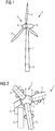
- Fig. 1 shows a wind turbine 1 according to an embodiment.
- the wind turbine 1 comprises a rotor 2 having one or more blades 3 connected to a hub 4 by means of a pitch bearing 5 (not shown in Fig. 1 ).
- the rotor 2 is connected to a generator (not shown) arranged inside a nacelle 6.
- the blades 3 are driven by wind to rotate and the wind's kinetic energy is converted into electrical energy by the generator in the nacelle 6.
- the nacelle 6 is arranged at the upper end of a tower 7 of the wind turbine 1.
- the tower 7 is erected on a foundation 8 such as a monopile or tripile.
- the foundation 8 is connected to and/or driven into the ground or seabed.
- FIG. 2 shows a detailed view of the rotor 2 of the wind turbine 1 of Fig. 1 .
- the rotor 2 comprises three blades 3.
- Each of the blades 3 is connected rotatably at a cylindrical root section 9 thereof to the hub 4 by means of a pitch bearing 5.
- each of the blades 3 is connected to an inner ring 10 ( Fig. 3 ) of the pitch bearing 5.
- an outer ring 11 of the pitch bearing 5 is connected to the hub 4.
- Each of the pitch bearings 5 is configured to support the respective blade 3 rotatably about a longitudinal axis L ( Fig. 2 ) of the blade 3.
- each of the pitch bearings 5 comprises roller elements 12 to allow a rotation of the inner ring 10, and thus of the blade 3, relative to the outer ring 11, and thus of the hub 4.
- Any suitable kind of pitch bearing can be used for the pitch bearing 5.
- any kind of suitable roller elements 12 can be applied.
- the pitch bearing 5 may comprise several rows of roller elements 12.
- metal arcs 13 for conducting a lightning current from the blade 3 to the hub 4 bypassing the pitch bearing 5.
- Each of the metal arcs 13 comprises a first arc portion 14, a second arc portion 15, and a bent portion 16.
- the first arc portion 14 and the second arc portion 15 are parallel to each other.
- the first arc portion 14 is electrically and mechanically connected to an extending portion 17 of the inner ring 10 of the pitch bearing 5.
- the second arc portion 15 is electrically and mechanically connected to an extending portion 18 of the outer ring 11 of the pitch bearing 5.
- Fig. 4 shows a perspective partial view of the metal arcs 13 and of the pitch bearing 5 of Fig. 3 .
- the extending portions 17, 18 are not shown in Fig. 4 .
- the rotor 3 comprises four metal arcs 13 each covering 90 degrees of a full circle.
- the first and second arc portions 14, 15 of each of the metal arcs 13 are arranged parallel to each other in a radial direction R of the blade 3.
- the metal arcs 13 are configured such that, when the blade 3 rotates relative to the hub 4 (i. e. the inner ring 10 of the pitch bearing 5 rotates relative to the outer ring 11), the first arc portion 14 is shifted relative to the second arc portion 15. In this manner, the metal arcs 13 allow rotation of the blade 3 relative to the hub 4, and at the same time an electrical connection between the blade 3 and the hub 4 is maintained in all rotation states by means of the metal arcs 13.
- a pitch bearing in wind turbines is usually designed to rotate 90 degrees only. In comparison, other rotating parts in a wind turbine are usually designed to rotate 360 degrees.
- each of the first and second arc portions 14, 15 of each of the metal arcs 13 comprises a main portion 38 and an end portion 39.
- the main portion 38 of the first arc portion 14 is freely removable from the blade 3 (i. e. from the inner ring 10) and the end portion 39 of the first arc portion 14 is mechanically and fixedly connected to the blade 3. Thereby, both the main and end portions 38, 39 are electrically connected to the blade 3.
- the main portion 38 of the second arc portion 15 is freely removable from the hub 4 (i. e. from the outer ring 11) and the end portion 39 of the second arc portion 15 is mechanically and fixedly connected to the hub 4.
- both the main and end portions 38, 39 of the second arc portion 15 are electrically connected to the hub 4.
- the metal arcs 13 are securely fix at their end portions 39 to the blade 3 and the hub 4, respectively.
- the blade 3 can be rotated relative to the hub 4 by having the freely removable main portions 39.
- Figs. 5-7 illustrate the behavior of one of the metal arcs 13 during rotation of the blade 3 relative to the hub 4.
- the figures show a plan view of the metal arc 13 of Fig. 4 .
- Figure 5 shows the metal arc 13 in an initial rotation state 19 of the blade 3 relative to the hub 4. In this initial rotation state 19, a length L1 of the first arc portion 14 and a length L2 of the second arc portion 15 are equal to each other.
- Fig. 6 shows the metal arc 13 of Fig. 5 in a first rotation state 20 in which the blade 3 was rotated relative to the hub 3 by a pitch angle ⁇ .
- a force F1 is applied to the first arc portion 14' and a force F2 is applied to the second arc portion 15', as shown in Fig. 6 .
- the force F1 is applied by the inner ring 10, i. e. by the extending portion 17 ( Fig. 3 ), to the first arc portion 14'.
- the force F2 is applied by the outer ring 11, i. e. by the extending portion 18 ( Fig. 3 ), to the second arc portion 15 '.
- the first arc portion 14' is shifted relative to the second arc portion 15'.
- a length L1' of the first arc portion 14' is reduced.
- a length L2' of the second arc portion 15' is increased by the same amount as the length L1' was reduced.
- the bent portion 16 has travelled due to the rotation of the blade 3 along the metal arc 13.
- a portion of the first arc portion 14 in the initial rotation state 19 has become the bent portion 16' in the first rotation state 20 ( Fig. 6 ).
- the bent portion 16 in the initial rotation state 19 ( Fig. 5 ) has become a portion of the second arc portion 15' in the first rotation state 20 ( Fig. 6 ).
- Fig. 7 shows the metal arc 13 of Fig. 5 in a second rotation state 21 of the blade 3 relative to the hub 4.
- a force F1' is applied to the first arc portion 14" and a force F2' is applied to the second arc portion 15". Due to the forces F1', F2', the first arc portion 14" is shifted relative to the second arc portion 15". As a consequence, a length L1" of the first arc portion 14" is increased. Further, a length L2" of the second arc portion 15" is reduced.
- Fig. 8 shows a partial cross-section and partial perspective view of a portion of the hub 4 and of the blade 3 along with a pitch bearing 5 and metal arcs 13 of the rotor 2 of Fig. 2 according to a first embodiment.
- the metal arcs 13 are configured such that the first arc portion 14 and the second arc portion 15 are parallel to each other in a radial direction R of the blade 3. Further, the metal arcs 13 are arranged outboard with respect to the pitch bearing 5.
- the root section 9 comprises in the cavity 23 in its hollow interior a metal ring 24.
- the metal ring 24 is attached to an inner wall 25 of a shell 26 of the blade 3.
- the down conductor 22 is split in the root section 9 into several branches 27 (some of them are illustrated in Fig. 8 ) and connected to the metal ring 24 at various positions thereof.
- the lightning current I is transmitted to the metal ring 24.
- the metal ring 24 is electrically connected to conductive bushings 28 of the blade 3.
- the bushings 28 are configured for mounting the blade root section 9 to an inner reinforcement plate 29, the inner ring 10 of the pitch bearing 5, and an outer reinforcement plate 30 by means of bolts 31.
- the bushings 28 are, for example, threaded bushings.
- Fig. 8 exemplarily some of the bolts 31 are denoted with a reference sign.
- the lightning current I is transmitted from the metal ring 24 to the bushings 28.
- the first arc portion 14 of each metal arc 13 is mechanically connected at its end portion 39 ( Fig. 4 ) to the outer surface 32 of the blade root section 9 such that they are in electrical connection with the bushings 28.
- the lightning current I is transmitted from the bushings to the first arc portion 14 of each of the several metal arcs 13.
- the second arc portion 15 of each of the several metal arcs 13 is mechanically connected to a protruding conductive portion 33.
- the protruding conductive portion 33 is fixed to the outer ring 11 of the pitch bearing 5.
- the lightning current I is transmitted from the second arc portion 15 of the several metal arcs 13 via the protruding portion 33 to the outer ring 11. From there on, the lightning current I is further transmitted via the nacelle 6 to the tower 7 and the foundation 8 to the ground.
- the bushings 28 and the bolts 31 would also provide a conductive path for the lightning current I
- the path via the metal arcs 13 is a low impedance path.
- the lightning current I is predominantly bypassed the pitch bearing 5 by using the metal arcs 13.
- Fig. 9 shows a first variant of the first embodiment of Fig. 8 .
- additional conductive elements 34 are provided which extend from the interior wall 25 of the blade 3 through the shell 26 to the outer surface 32.
- the conductive elements 34 are arranged above the bushings 28, i. e. outboard of the bushings 28.
- the conductive elements 34 are electrically isolated from the bushings 28 and the bolts 31.
- the first arc portion 14 of the metal arcs 13 are mechanically connected to the outer surface 32 of the blade root section 9 such that they are in electrical connection with the conductive elements 34.
- the lightning current I is transmitted by the down conductor 22, the branches 27, the metal ring 24 and the conductive elements 34 to the metal arcs 13. From the metal arcs 13, the lightning current I is transmitted to the protruding portion 33 to the outer ring 11 of the pitch bearing 5. As the conductive elements 34 are electrically isolated from the bushings 28, no lightning current is transmitted to the inner ring 10. Therefore, lightning current entering the pitch bearing can be even better prevented.
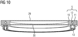
- the metal arcs 13 are arranged outboard of the pitch bearing. However, the metal arcs can also be arranged inboard of the pitch bearing as shown schematically in Fig. 10 .
- Fig. 11 shows a second embodiment of the rotor 2 of the wind turbine 1 of Figs. 1 and 2 .
- the metal arcs 13 are configured such that the first and second arc portions 14 and 15 are arranged parallel to each other in a longitudinal direction L of the blade 3.
- a conductive circumferential angled protruding portion 35 and an angled bracket 36 are provided.
- the conductive circumferential angled protruding portion 35 and the angled bracket 36 are attached to the root section 9 of the blade 3.
- a metallic plate 37 is attached to the hub, e.g., to the outer ring 11 of the pitch bearing 5.
- a lightning current I striking the blade 3 is transmitted via the down conductor 22, the metal ring 29, and the circumferential angled protruding portion 35 to the metal arcs 13. From the metal arcs 13, the lighting current I is transmitted to the metal plate 37 to the hub 4.
- the electrical path from the metal ring 29 to the conductive protruding portion 25 in the second embodiment can be configured via the bushings 28 ( Fig. 8 ) or via additional conductive elements 34 ( Fig. 9 ).
Landscapes
- Engineering & Computer Science (AREA)
- Life Sciences & Earth Sciences (AREA)
- Sustainable Development (AREA)
- Sustainable Energy (AREA)
- Chemical & Material Sciences (AREA)
- Combustion & Propulsion (AREA)
- Mechanical Engineering (AREA)
- General Engineering & Computer Science (AREA)
- Physics & Mathematics (AREA)
- Fluid Mechanics (AREA)
- Wind Motors (AREA)
Abstract
Description
- The present invention relates to a rotor for a wind turbine and the wind turbine.
- Lightning protection is one of the biggest challenges in wind turbine design. Wind turbines are usually the tallest structures in a local environment, especially in offshore wind parks. Therefore, the probability of being hit by lightning is very high. Lightning strikes predominantly the tallest point of the wind turbine which is usually the blade.
- Lightning currents need to be transferred between various rotating parts of the wind turbine. For example, the lightning current that flows through the blade needs to be transmitted to the ground via the hub, the nacelle and the tower. Usually, the blade is rotatably connected to the hub, the hub is rotatably connected to the nacelle and the nacelle is rotatably connected to the tower. Due to the parts rotating relative to each other, cables for conducting a lightning current are in most cases unsuitable. The pitch bearing at the connection of the blade to the hub is one of the critical parts where an improved lightning protection system is required.
- Conventionally, for example, carbon brushes are used to conduct lightning current bypassing the bearing. However, the brushes are sliding parts which get worn out quickly. Thus, they need to be replaced frequently which is time and cost consuming. Alternatively, spark gaps are applied. However, they have the disadvantage that the blades tend to accumulate static electricity. This causes the risk of flashovers if sufficient grounding is not provided. Alternatively, the lightning current is passed from the blade down conductor through a high-voltage cable through an opening at the center of the inner ring of the pitch bearing. However, lightning current passing through the high-voltage cable generates huge magnetic fields inside the hub. This can damage the electronic components inside the hub. A further conventional approach is to directly pass a lightning current through the bearing. However, this causes a high risk of damaging the bearing. Replacing a bearing after starting operation of the wind turbine is a very expensive and time-consuming process.
- It is one object of the present invention to provide an improved rotor for a wind turbine and an improved wind turbine.
- Accordingly, a rotor for a wind turbine is provided. The rotor comprises a blade and a hub. The rotor further comprises a pitch bearing configured to support the blade rotatably about a longitudinal axis of the blade and relative to the hub. Furthermore, the rotor comprises one or more metal arcs for conducting a lightning current from the blade to the hub. Each of the one or more metal arcs comprises a first arc portion electrically and mechanically connected to the blade. Each of the one or more metal arcs comprises a second arc portion electrically and mechanically connected to the hub. Further, each of the one or more metal arcs comprises a bent portion connecting the first and second arc portions. Each of the one or more metal arcs is configured such that, when the blade rotates relative to the hub, the first arc portion is shifted relative to the second arc portion and a length of the first arc portion is reduced or increased at the expense of an increase or decrease of a length of the second arc portion.
- This allows to conduct a lightning current from the blade to the hub bypassing the pitch bearing and still allows rotation of the blade relative to the hub. In particular, the metal arcs provide a low impedance path for the lightning current. Thus, damaging of the pitch bearing by a lightning current is avoided.
- Furthermore, having the one or more metal arcs avoids sliding parts as in carbon brushes. Thus, the lifetime of the metal arcs is much larger than that of carbon brushes.
- In addition, high magnetic fields inside of the hub due to a lightning current are prevented.
- The wind turbine is an apparatus to convert the wind's kinetic energy into electrical energy. The wind turbine comprises, for example, the rotor having one or more of the blades and one or more of the pitch bearings. Each of the blades is connected rotatably to the hub by means of one of the pitch bearings. The hub is connected to a nacelle including a generator. The wind turbine further comprises a tower holding, at its top end, the nacelle. The tower of the wind turbine may be connected via a transition piece to a foundation of the wind turbine, such as a monopile in the seabed.
- The one or more metal arcs are, in particular, made from a flexible metal. The one or more metal arcs are, for example, made from spring steel.
- The rotor comprises, for example, one metal arc covering 360 degrees, two semicircular metal arcs covering each 180 degrees, three metal arcs covering each 120 degrees or four metal arcs covering each 90 degrees.
- The metal arcs are, in particular, arranged along a circumference of the blade. The circumference of the blade is, for example, an outer circumference of the blade.
- The second arc portion is, for example, arranged parallel to the first arc portion. Then, when the blade rotates relative to the hub, the first arc portion of each of the one or more metal arcs is shifted relative to the second arc portion such that the first and second arc portions remain parallel to each other.
- According to an embodiment, each of the one or more metal arcs is configured such that in an initial rotation state of the blade relative to the hub, the length of the first arc portion is equal to the length of the second arc portion, and in a rotation state of the blade relative to the hub offset from the initial rotation state, the length of the first arc portion is different from the length of the second arc portion.
- Having the first and second arc portions of the one or more metal arcs of equal length in the initial rotation state of the blade provides a symmetric and robust configuration of the metal arcs and their electrically and mechanically connection with the blade and the hub.
- The initial rotation state of the blade relative to the hub corresponds, in particular, to a blade pitch angle of zero.
- According to a further embodiment, the first arc portion of each of the one or more metal arcs comprises a main portion connected to the bent portion, the bent portion and the main portion being freely movable with respect to the blade. Further, the first arc portion of each of the one or more metal arcs comprises an end portion connected to the main portion, the end portion being fixedly connected to the blade. Further, both the main and end portions are electrically connected to the blade. Furthermore, the second arc portion of each of the one or more metal arcs comprises a main portion connected to the bent portion, the bent portion and the main portion being freely movable with respect to the hub. Further, the second arc portion of each of the one or more metal arcs comprises an end portion connected to the main portion, the end portion being fixedly connected to the hub, and both the main and end portions being electrically connected to the hub.
- Having the main portions being freely removable and the end portions being fixedly connected allows to securely fix the one or more metal arcs to the blade and the hub and at the same time allow rotation of the blade relative to the hub over a large angular range.
- In embodiments, for each of the first and second arc portions of each of the one or more metal arcs, the main portion is larger than the end portion in the initial rotation state of the blade relative to the hub. In particular, for each of the first and second arc portions of each of the one or more metal arcs, the main portion covers a larger arc segment of the metal arc compared to the end portion. For example, the length of the main portion along the arc comprises more than 70%, more than 80%, more than 90%, more than 95% of the first/second arc portion in the initial rotation state.
- According to a further embodiment, the blade comprises a blade root section and the first arc portion of each of the one or more metal arcs is electrically and mechanically connected to the blade root section.
- According to a further embodiment, the one or more metal arcs are arranged along an outer circumference of the blade.
- Having the one or more metal arcs arranged along an outer circumference of the blade allows to better prevent high magnetic fields inside the hub due to lightning current passing through the metal arcs.
- In particular, the one or more metal arcs are arranged along an outer circumference of the cylindrical blade root section.
- According to a further embodiment, the blade comprises in its hollow interior an interior conductive ring for connection with one or more down conductors of the blade. The interior conductive ring is electrically connected with the first arc portion of each of the one or more metal arcs.
- Having the interior conductive ring allows to distribute a lightning current from the blade, e.g., from the blade down conductor, evenly to the one or more first arc portions of the one or more metal arcs.
- The interior conductive ring is, in particular, connected to an interior wall of a blade shell forming an inner cavity of the blade. The interior conductive ring is, in particular, connected to the interior wall along its entire circumference. The interior conductive ring is, in particular, made from metal.
- The one or more down conductors may, for example, be split and connected to the interior conductive ring at various positions thereof.
- According to a further embodiment, the interior conductive ring of the blade is electrically connected with the first arc portion of each of the one or more metal arcs by means of conductive elements extending from the blade interior to the blade exterior.
- Having the conductive elements of the blade, allows to electrically connect the interior conductive ring with the first arc portion of the one or more metal arcs in the case that the one or more metal arcs are arranged along the outer circumference of the blade.
- The conductive elements are, in particular, extending through the shell of the blade. The conductive elements are, in particular, made from metal.
- According to a further embodiment, the pitch bearing comprises an inner ring mounted to the blade and an outer ring mounted to the hub. Further, the conductive elements of the blade are conductive bushings configured for mounting the blade to the inner ring of the pitch bearing by means of fasteners.
- By using the conductive bushings configured for mounting the blade to the pitch bearing which are available anyway, no additional conductive elements are required for connecting the interior conductive ring of the blade with the one or more metal arcs.
- The conductive bushings are, for example, threaded bushings. The fasteners are, for example, bolts.
- In embodiments, the inner ring of the pitch bearing may be mounted to the hub and the outer ring of the pitch bearing may be mounted to the blade.
- According to a further embodiment, the pitch bearing comprises an inner ring mounted to the blade and an outer ring mounted to the hub. Further, the conductive elements of the blade are arranged spaced apart and electrically isolated from conductive bushings of the blade being configured for mounting the blade to the inner ring of the pitch bearing by means of fasteners.
- By using conductive elements of the blade which are arranged spaced apart and electrically isolated from the conductive bushings of the blade being configured for mounting the blade to the pitch bearing, it can be better avoided that lightning current is transmitted via the conductive bushings and the fasteners to the pitch bearing. Thus, it is better ensured that the lightning current is transferred completely by the one or more metal arcs and no current flows through the pitch bearing.
- According to a further embodiment, the second arc portion of each of the one or more metal arcs is electrically and mechanically connected to an outer ring of the pitch bearing. In addition, the outer ring of the pitch bearing is electrically and mechanically connected to the hub.
- According to a further embodiment, the hub comprises an outer circumferential protruding portion protruding in the direction of the blade. Furthermore, the second arc portion of each of the one or more metal arcs is electrically and mechanically connected to the protruding portion of the hub.
- The protruding portion may protrude solely in the longitudinal direction of the blade. Alternatively, the protruding portion may comprise in addition to the portion protruding in the longitudinal direction of the blade also a portion protruding in a radial direction of the blade. Thus, the protruding portion has an angled configuration. The radial protruding portion may be configured for being connected to the second arc portion in the case that the first and second arc portions of each of the one or more metal arcs are arranged parallel to each other in a longitudinal direction of the blade.
- According to a further embodiment, the one or more metal arcs are arranged outboard with respect to the pitch bearing.
- Having the one or more metal arcs arranged outboard with respect to the pitch bearing allows to even better transmit lightning current from the blade to the hub bypassing the pitch bearing.
- In embodiments, the one or more metal arcs may also be arranged inboard with respect to the pitch bearing. This may be in particular the case when the first and second arc portions of each of the one or more metal arcs are arranged parallel to each other in a radial direction of the blade.
- According to a further embodiment, the first and second arc portions of each of the one or more metal arcs are arranged parallel to each other in a radial direction of the blade.
- Having this parallel configuration of the first and second arc portions in the radial direction of the blade allows a direct transmission of the rotational force of the blade to the one or more metal arcs.
- In particular, the first and second arc portions are arranged parallel to each other in a radial direction of the blade root section.
- According to a further embodiment, the first and second arc portions of each of the one or more metal arcs are arranged parallel to each other in a longitudinal direction of the blade.
- Having this parallel configuration of the first and second arc portions in the longitudinal direction of the blade provides a further design option for the rotor of the wind turbine blade.
- According to a further aspect, a wind turbine is provided. The wind turbine comprises a rotor as described above.
- Further possible implementations or alternative solutions of the invention also encompass combinations - that are not explicitly mentioned herein - of features described above or below with regard to the embodiments. The person skilled in the art may also add individual or isolated aspects and features to the most basic form of the invention.
- Further embodiments, features and advantages of the present invention will become apparent from the subsequent description and dependent claims, taken in conjunction with the accompanying drawings, in which:
-
Fig. 1 shows a wind turbine according to an embodiment; -
Fig. 2 shows a detailed view of a rotor with three blades and a hub of the wind turbine ofFig. 1 ; -
Fig. 3 shows a pitch bearing and metal arcs of the rotor ofFig. 2 illustrating a principle of the invention; -
Fig. 4 shows a perspective partial view of the metal arcs and of the pitch bearing ofFig. 3 ; -
Fig. 5 shows a plan view of one of the metal arcs ofFig. 4 in an initial rotation state of the blade relative to the hub; -
Fig. 6 shows the metal arc ofFig. 5 in a first rotation state of the blade relative to the hub offset from the initial rotation state; -
Fig. 7 shows the metal arc ofFig. 5 in a second rotation state of the blade relative to the hub offset from the initial rotation state; -
Fig. 8 shows a partial cross-section and partial perspective view of a portion of the hub and of the blade along with a pitch bearing and metal arcs of the rotor ofFig. 2 according to a first embodiment; -
Fig. 9 shows a first variant of the first embodiment ofFig. 8 ; -
Fig. 10 illustrates a second variant of the first embodiment ofFig. 8 ; and -
Fig. 11 shows a partial cross-section and partial perspective view of a portion of the hub and of the blade along with a pitch bearing and metal arcs of the rotor ofFig. 2 according to a second embodiment. - In the Figures, like reference numerals designate like or functionally equivalent elements, unless otherwise indicated.
-
Fig. 1 shows awind turbine 1 according to an embodiment. Thewind turbine 1 comprises arotor 2 having one ormore blades 3 connected to ahub 4 by means of a pitch bearing 5 (not shown inFig. 1 ). Therotor 2 is connected to a generator (not shown) arranged inside a nacelle 6. During operation of thewind turbine 1, theblades 3 are driven by wind to rotate and the wind's kinetic energy is converted into electrical energy by the generator in the nacelle 6. The nacelle 6 is arranged at the upper end of a tower 7 of thewind turbine 1. The tower 7 is erected on afoundation 8 such as a monopile or tripile. Thefoundation 8 is connected to and/or driven into the ground or seabed. -
Figure 2 shows a detailed view of therotor 2 of thewind turbine 1 ofFig. 1 . Therotor 2 comprises threeblades 3. Each of theblades 3 is connected rotatably at acylindrical root section 9 thereof to thehub 4 by means of apitch bearing 5. For example, each of theblades 3 is connected to an inner ring 10 (Fig. 3 ) of thepitch bearing 5. Further, anouter ring 11 of thepitch bearing 5 is connected to thehub 4. Each of thepitch bearings 5 is configured to support therespective blade 3 rotatably about a longitudinal axis L (Fig. 2 ) of theblade 3. By rotating theblade 3 relative to thehub 4,
the angle of attack of therespective blade 3 according to the wind speed can be adjusted to control the rotational speed of theblade 3. - As schematically shown in
Fig. 3 , each of thepitch bearings 5 comprisesroller elements 12 to allow a rotation of theinner ring 10, and thus of theblade 3, relative to theouter ring 11, and thus of thehub 4. Any suitable kind of pitch bearing can be used for thepitch bearing 5. In particular, any kind ofsuitable roller elements 12 can be applied. Further, thepitch bearing 5 may comprise several rows ofroller elements 12. - Further shown in
Fig. 3 aremetal arcs 13 for conducting a lightning current from theblade 3 to thehub 4 bypassing thepitch bearing 5. Each of the metal arcs 13 comprises afirst arc portion 14, asecond arc portion 15, and abent portion 16. Thefirst arc portion 14 and thesecond arc portion 15 are parallel to each other. Thefirst arc portion 14 is electrically and mechanically connected to an extendingportion 17 of theinner ring 10 of thepitch bearing 5. Thesecond arc portion 15 is electrically and mechanically connected to an extendingportion 18 of theouter ring 11 of thepitch bearing 5. -
Fig. 4 shows a perspective partial view of the metal arcs 13 and of the pitch bearing 5 ofFig. 3 . For illustration purposes, the extendingportions Fig. 4 . In this example, therotor 3 comprises four metal arcs 13 each covering 90 degrees of a full circle. Further, in this example, the first andsecond arc portions blade 3. - The metal arcs 13 are configured such that, when the
blade 3 rotates relative to the hub 4 (i. e. theinner ring 10 of thepitch bearing 5 rotates relative to the outer ring 11), thefirst arc portion 14 is shifted relative to thesecond arc portion 15. In this manner, the metal arcs 13 allow rotation of theblade 3 relative to thehub 4, and at the same time an electrical connection between theblade 3 and thehub 4 is maintained in all rotation states by means of the metal arcs 13. This is in particular the case, as a pitch bearing in wind turbines is usually designed to rotate 90 degrees only. In comparison, other rotating parts in a wind turbine are usually designed to rotate 360 degrees. - As shown in
Fig. 4 , each of the first andsecond arc portions main portion 38 and anend portion 39. Themain portion 38 of thefirst arc portion 14 is freely removable from the blade 3 (i. e. from the inner ring 10) and theend portion 39 of thefirst arc portion 14 is mechanically and fixedly connected to theblade 3. Thereby, both the main and endportions blade 3. Likewise, themain portion 38 of thesecond arc portion 15 is freely removable from the hub 4 (i. e. from the outer ring 11) and theend portion 39 of thesecond arc portion 15 is mechanically and fixedly connected to thehub 4. Thereby, both the main and endportions second arc portion 15 are electrically connected to thehub 4. Thus, the metal arcs 13 are securely fix at theirend portions 39 to theblade 3 and thehub 4, respectively. At the same time, theblade 3 can be rotated relative to thehub 4 by having the freely removablemain portions 39. -
Figs. 5-7 illustrate the behavior of one of the metal arcs 13 during rotation of theblade 3 relative to thehub 4. The figures show a plan view of themetal arc 13 ofFig. 4 .Figure 5 shows themetal arc 13 in aninitial rotation state 19 of theblade 3 relative to thehub 4. In thisinitial rotation state 19, a length L1 of thefirst arc portion 14 and a length L2 of thesecond arc portion 15 are equal to each other. -
Fig. 6 shows themetal arc 13 ofFig. 5 in afirst rotation state 20 in which theblade 3 was rotated relative to thehub 3 by a pitch angle α. When theblade 3 rotates relative to thehub 4, a force F1 is applied to the first arc portion 14' and a force F2 is applied to the second arc portion 15', as shown inFig. 6 . Thereby, the force F1 is applied by theinner ring 10, i. e. by the extending portion 17 (Fig. 3 ), to the first arc portion 14'. Further, the force F2 is applied by theouter ring 11, i. e. by the extending portion 18 (Fig. 3 ), to the second arc portion 15 '. Due to the forces F1, F2, the first arc portion 14' is shifted relative to the second arc portion 15'. As a consequence, a length L1' of the first arc portion 14'is reduced. Further, a length L2' of the second arc portion 15' is increased by the same amount as the length L1' was reduced. In other words, thebent portion 16 has travelled due to the rotation of theblade 3 along themetal arc 13. As a consequence, a portion of thefirst arc portion 14 in the initial rotation state 19 (Fig. 5 ) has become the bent portion 16' in the first rotation state 20 (Fig. 6 ). Further, thebent portion 16 in the initial rotation state 19 (Fig. 5 ) has become a portion of the second arc portion 15' in the first rotation state 20 (Fig. 6 ). -
Fig. 7 shows themetal arc 13 ofFig. 5 in asecond rotation state 21 of theblade 3 relative to thehub 4. Here, a force F1' is applied to thefirst arc portion 14" and a force F2' is applied to thesecond arc portion 15". Due to the forces F1', F2', thefirst arc portion 14" is shifted relative to thesecond arc portion 15". As a consequence, a length L1" of thefirst arc portion 14" is increased. Further, a length L2" of thesecond arc portion 15" is reduced. -
Fig. 8 shows a partial cross-section and partial perspective view of a portion of thehub 4 and of theblade 3 along with apitch bearing 5 and metal arcs 13 of therotor 2 ofFig. 2 according to a first embodiment. As inFig. 3 , which showed the principle of the metal arcs 13, in the first embodiment shown inFig. 8 , the metal arcs 13 are configured such that thefirst arc portion 14 and thesecond arc portion 15 are parallel to each other in a radial direction R of theblade 3. Further, the metal arcs 13 are arranged outboard with respect to thepitch bearing 5. - When a lightning strikes the
blade 3, the lightning current I is transmitted via adown conductor 22 to theroot section 9 of theblade 3. Theroot section 9 comprises in thecavity 23 in its hollow interior ametal ring 24. Themetal ring 24 is attached to aninner wall 25 of ashell 26 of theblade 3. The downconductor 22 is split in theroot section 9 into several branches 27 (some of them are illustrated inFig. 8 ) and connected to themetal ring 24 at various positions thereof. Thus, the lightning current I is transmitted to themetal ring 24. - The
metal ring 24 is electrically connected toconductive bushings 28 of theblade 3. Thebushings 28 are configured for mounting theblade root section 9 to aninner reinforcement plate 29, theinner ring 10 of thepitch bearing 5, and anouter reinforcement plate 30 by means ofbolts 31. Thebushings 28 are, for example, threaded bushings. InFig. 8 , exemplarily some of thebolts 31 are denoted with a reference sign. Thus, the lightning current I is transmitted from themetal ring 24 to thebushings 28. - The
first arc portion 14 of eachmetal arc 13 is mechanically connected at its end portion 39 (Fig. 4 ) to theouter surface 32 of theblade root section 9 such that they are in electrical connection with thebushings 28. Thus, the lightning current I is transmitted from the bushings to thefirst arc portion 14 of each of the several metal arcs 13. From thefirst arc portion 14, the lightning current I is transmitted via thebent portion 16 to thesecond arc portion 15. Thesecond arc portion 15 of each of the several metal arcs 13 is mechanically connected to a protrudingconductive portion 33. The protrudingconductive portion 33 is fixed to theouter ring 11 of thepitch bearing 5. Thus, the lightning current I is transmitted from thesecond arc portion 15 of the several metal arcs 13 via the protrudingportion 33 to theouter ring 11. From there on, the lightning current I is further transmitted via the nacelle 6 to the tower 7 and thefoundation 8 to the ground. - While the
bushings 28 and thebolts 31 would also provide a conductive path for the lightning current I, the path via the metal arcs 13 is a low impedance path. Thus, the lightning current I is predominantly bypassed thepitch bearing 5 by using the metal arcs 13. -
Fig. 9 shows a first variant of the first embodiment ofFig. 8 . InFig. 9 , additionalconductive elements 34 are provided which extend from theinterior wall 25 of theblade 3 through theshell 26 to theouter surface 32. Theconductive elements 34 are arranged above thebushings 28, i. e. outboard of thebushings 28. Theconductive elements 34 are electrically isolated from thebushings 28 and thebolts 31. Thefirst arc portion 14 of the metal arcs 13 are mechanically connected to theouter surface 32 of theblade root section 9 such that they are in electrical connection with theconductive elements 34. - When a lightning strikes the
blade 3, the lightning current I is transmitted by thedown conductor 22, thebranches 27, themetal ring 24 and theconductive elements 34 to the metal arcs 13. From the metal arcs 13, the lightning current I is transmitted to the protrudingportion 33 to theouter ring 11 of thepitch bearing 5. As theconductive elements 34 are electrically isolated from thebushings 28, no lightning current is transmitted to theinner ring 10. Therefore, lightning current entering the pitch bearing can be even better prevented. - In
Figs. 8 and9 , the metal arcs 13 are arranged outboard of the pitch bearing. However, the metal arcs can also be arranged inboard of the pitch bearing as shown schematically inFig. 10 . -
Fig. 11 shows a second embodiment of therotor 2 of thewind turbine 1 ofFigs. 1 and 2 . In this embodiment, the metal arcs 13 are configured such that the first andsecond arc portions blade 3. In the following, only differences with respect to the embodiment ofFig. 8 are described. - In order to electrically and mechanically connect the
metal ring 24 with the metal arcs 13, a conductive circumferential angled protrudingportion 35 and anangled bracket 36 are provided. The conductive circumferential angled protrudingportion 35 and theangled bracket 36 are attached to theroot section 9 of theblade 3. Further, a metallic plate 37 is attached to the hub, e.g., to theouter ring 11 of thepitch bearing 5. A lightning current I striking theblade 3 is transmitted via thedown conductor 22, themetal ring 29, and the circumferential angled protrudingportion 35 to the metal arcs 13. From the metal arcs 13, the lighting current I is transmitted to the metal plate 37 to thehub 4. - Although not shown in detail in
Fig. 11 , the electrical path from themetal ring 29 to the conductive protrudingportion 25 in the second embodiment can be configured via the bushings 28 (Fig. 8 ) or via additional conductive elements 34 (Fig. 9 ). - Although the present invention has been described in accordance with preferred embodiments, it is obvious for the person skilled in the art that modifications are possible in all embodiments.
Claims (15)
- A rotor (2) for a wind turbine (1), comprising:a blade (3),a hub (4),a pitch bearing (5) being configured to support the blade (3) rotatably about a longitudinal axis (L) of the blade (3) and relative to the hub (4), andone or more metal arcs (13) for conducting a lightning current (I) from the blade (3) to the hub (4),wherein each of the one or more metal arcs (13) comprises :a first arc portion (14, 14', 14") electrically and mechanically connected to the blade (3),a second arc portion (15, 15', 15") electrically and mechanically connected to the hub (4), anda bent portion (16, 16', 16") connecting the first and second arc portions (14, 14', 14", 15, 15', 15"), andwherein each of the one or more metal arcs (13) is configured such that, when the blade (3) rotates relative to the hub (4), the first arc portion (14, 14', 14") is shifted relative to the second arc portion (15, 15', 15") and a length (L1, L1', L1") of the first arc portion (14, 14', 14") is reduced or increased at the expense of an increase or decrease of a length (L2, L2', L2") of the second arc portion (15, 15', 15").
- The rotor according to claim 1,
wherein each of the one or more metal arcs (13) is configured such that in an initial rotation state (19) of the blade (3) relative to the hub (4), the length (L1) of the first arc portion (14, 14', 14") is equal to the length (L2) of the second arc portion (15, 15', 15"), and in a rotation state (20, 21) of the blade (3) relative to the hub (4) offset from the initial rotation state (19), the length (L1', L1") of the first arc portion (14, 14', 14") is different from the length (L2', L2") of the second arc portion (15, 15', 15"). - The rotor according to claim 1 or 2, wherein:the first arc portion (14, 14', 14") of each of the one or more metal arcs (13) comprises:a main portion (38) connected to the bent portion (16, 16', 16"), the bent portion (16, 16', 16") and the main portion (38) being freely movable with respect to the blade (3), andan end portion (39) connected to the main portion (38), the end portion (39) being fixedly connected to the blade (3), and both the main and end portions (38, 39) being electrically connected to the blade (3); andthe second arc portion (15, 15', 15") of each of the one or more metal arcs (13) comprises:a main portion (38) connected to the bent portion (16, 16', 16"), the bent portion (16, 16', 16") and the main portion (38) being freely movable with respect to the hub (4), andan end portion (39) connected to the main portion (38), the end portion (39) being fixedly connected to the hub (4), and both the main and end portions (38, 39) being electrically connected to the hub (4).
- The rotor according to one of claims 1 - 3,
wherein the blade (3) comprises a blade root section (9) and the first arc portion (14, 14', 14") of each of the one or more metal arcs (13) is electrically and mechanically connected to the blade root section (9). - The rotor according to one of claims 1 - 4,
wherein the one or more metal arcs (13) are arranged along an outer circumference (32) of the blade (3). - The rotor according to one of claims 1 - 5,
wherein the blade (3) comprises in its hollow interior (23) an interior conductive ring (24) for connection with one or more down conductors (22) of the blade (3), the interior conductive ring (24) being electrically connected with the first arc portion (14, 14', 14") of each of the one or more metal arcs (13). - The rotor according to claim 6,
wherein the interior conductive ring (24) of the blade (3) is electrically connected with the first arc portion (14, 14', 14") of each of the one or more metal arcs (13) by means of conductive elements (28, 34) extending from the blade interior (25) to the blade exterior (32). - The rotor according to claim 7,
wherein the pitch bearing (5) comprises an inner ring (10) mounted to the blade (3) and an outer ring (11) mounted to the hub (4), and the conductive elements (28) of the blade (3) are conductive bushings (28) configured for mounting the blade (3) to the inner ring (10) of the pitch bearing (5) by means of fasteners (31). - The rotor according to claim 7,
wherein the pitch bearing (5) comprises an inner ring (10) mounted to the blade (3) and an outer ring (11) mounted to the hub (4), and the conductive elements (34) of the blade (3) are arranged spaced apart and electrically isolated from conductive bushings (28) of the blade (3) being configured for mounting the blade (3) to the inner ring (10) of the pitch bearing (5) by means of fasteners (31). - The rotor according to one of claims 1 - 9,
wherein the second arc portion (15, 15', 15") of each of the one or more metal arcs (13) is electrically and mechanically connected to an outer ring (11) of the pitch bearing (5) and the outer ring (11) of the pitch bearing (5) is electrically and mechanically connected to the hub (4). - The rotor according to one of claims 1 - 10,
wherein the hub (4) comprises an outer circumferential protruding portion (33, 37) protruding in the direction of the blade (3), and the second arc portion (15, 15', 15") of each of the one or more metal arcs (13) is electrically and mechanically connected to the protruding portion (33, 37) of the hub (4). - The rotor according to one of claims 1 - 11,
wherein the one or more metal arcs (13) are arranged outboard with respect to the pitch bearing (5). - The rotor according to one of claims 1 - 12,
wherein the first and second arc portions (14, 14', 14", 15, 15', 15") of each of the one or more metal arcs (13) are arranged parallel to each other in a radial direction (R) of the blade (3). - The rotor according to one of claims 1 - 12,
wherein the first and second arc portions (14, 14', 14", 15, 15', 15") of each of the one or more metal arcs (13) are arranged parallel to each other in a longitudinal direction (L) of the blade (3). - A wind turbine (1) comprising a rotor (2) according to one of claims 1 - 14.
Priority Applications (3)
| Application Number | Priority Date | Filing Date | Title |
|---|---|---|---|
| EP19176665.8A EP3744972B1 (en) | 2019-05-27 | 2019-05-27 | Rotor for a wind turbine and wind turbine |
| US16/877,672 US11499533B2 (en) | 2019-05-27 | 2020-05-19 | Rotor for a wind turbine and wind turbine |
| CN202010461161.6A CN111997847B (en) | 2019-05-27 | 2020-05-27 | Rotor for a wind turbine and wind turbine |
Applications Claiming Priority (1)
| Application Number | Priority Date | Filing Date | Title |
|---|---|---|---|
| EP19176665.8A EP3744972B1 (en) | 2019-05-27 | 2019-05-27 | Rotor for a wind turbine and wind turbine |
Publications (2)
| Publication Number | Publication Date |
|---|---|
| EP3744972A1 true EP3744972A1 (en) | 2020-12-02 |
| EP3744972B1 EP3744972B1 (en) | 2023-01-11 |
Family
ID=66655194
Family Applications (1)
| Application Number | Title | Priority Date | Filing Date |
|---|---|---|---|
| EP19176665.8A Active EP3744972B1 (en) | 2019-05-27 | 2019-05-27 | Rotor for a wind turbine and wind turbine |
Country Status (3)
| Country | Link |
|---|---|
| US (1) | US11499533B2 (en) |
| EP (1) | EP3744972B1 (en) |
| CN (1) | CN111997847B (en) |
Cited By (1)
| Publication number | Priority date | Publication date | Assignee | Title |
|---|---|---|---|---|
| EP4556711A1 (en) * | 2023-11-16 | 2025-05-21 | Siemens Gamesa Renewable Energy Innovation & Technology S.L. | Wind turbine rotor blade improved for lightning protection |
Families Citing this family (4)
| Publication number | Priority date | Publication date | Assignee | Title |
|---|---|---|---|---|
| ES2966488T3 (en) * | 2019-06-03 | 2024-04-22 | Lm Wind Power As | Bulkhead for a wind turbine blade and procedure for installing a bulkhead on a wind turbine blade |
| EP4293222A1 (en) * | 2022-06-17 | 2023-12-20 | Siemens Gamesa Renewable Energy A/S | Rotor blade with lightning protection system, wind turbine and assembly method |
| CN116498510B (en) * | 2023-04-28 | 2024-09-20 | 华能江西清洁能源有限责任公司 | A wind turbine variable pitch bearing reinforcement support |
| CN118499204B (en) * | 2024-06-12 | 2025-04-25 | 长江三峡集团福建能源投资有限公司 | Lightning protection device for wind turbine blades |
Citations (3)
| Publication number | Priority date | Publication date | Assignee | Title |
|---|---|---|---|---|
| EP0718495A1 (en) * | 1994-12-22 | 1996-06-26 | AUTOFLUG ENERGIETECHNIK GmbH + CO. | Lightning protection for wind turbine |
| KR20120039139A (en) * | 2010-10-15 | 2012-04-25 | 삼성중공업 주식회사 | Lightning protection system for wind turbine |
| EP2708743A1 (en) * | 2011-05-10 | 2014-03-19 | Mitsubishi Heavy Industries, Ltd. | Windmill |
Family Cites Families (14)
| Publication number | Priority date | Publication date | Assignee | Title |
|---|---|---|---|---|
| DE19926278C1 (en) * | 1999-06-09 | 2001-02-15 | Kostal Leopold Gmbh & Co Kg | Device for transmitting energy |
| DE20003965U1 (en) * | 2000-02-24 | 2000-07-13 | Petri Ag, 63743 Aschaffenburg | Device for transmitting electrical current between two components of a steering device for motor vehicles that can be rotated relative to one another |
| JP2002247746A (en) * | 2001-02-15 | 2002-08-30 | Sumitomo Wiring Syst Ltd | Cable reel |
| FR2833415B1 (en) * | 2001-12-12 | 2008-08-08 | Delphi Tech Inc | DEVICE FOR ELECTRICAL CONNECTION BETWEEN TWO RELATIVE ROTATING BODIES |
| DE10235862C1 (en) * | 2002-08-05 | 2003-11-13 | Freudenberg Carl Kg | Flat ribbon cable, connecting inner and outer rotating housing sections e.g. in a motor vehicle steering system, has magnetic/magnetized end zones to cling to the housing surfaces without becoming loose |
| DK177270B1 (en) * | 2002-11-12 | 2012-09-10 | Lm Wind Power As | Lightning protection of pitch-regulated wind turbine wings |
| CN103174603A (en) * | 2011-12-23 | 2013-06-26 | 新疆金风科技股份有限公司 | Lightning protection device of wind generating set and wind generating set |
| CN102661240A (en) * | 2012-05-16 | 2012-09-12 | 国电联合动力技术有限公司 | Wind wheel vane anti-lightning device for wind generating set and mounting method thereof |
| US20150056078A1 (en) * | 2013-08-22 | 2015-02-26 | General Electric Company | Pitch bearing assembly with stiffener |
| EP3080447B1 (en) * | 2013-12-09 | 2019-06-12 | Vestas Wind Systems A/S | Rotor-blade discharge unit for wind turbines |
| EP3234352B1 (en) * | 2014-12-18 | 2018-09-19 | Vestas Wind Systems A/S | A lightning current transfer unit for a wind turbine |
| CN105207034B (en) * | 2015-10-16 | 2018-02-13 | 中国电子科技集团公司第三十八研究所 | A kind of cable suitable for radar rotary transfer turns around device |
| ES2662951B1 (en) * | 2016-10-05 | 2019-01-15 | Siemens Gamesa Renewable Energy Innovation & Technology SL | Lightning current transmission system for wind turbines |
| CN109209755B (en) * | 2018-09-12 | 2020-01-17 | 太原重工股份有限公司 | Hub device for wind generating set |
-
2019
- 2019-05-27 EP EP19176665.8A patent/EP3744972B1/en active Active
-
2020
- 2020-05-19 US US16/877,672 patent/US11499533B2/en active Active
- 2020-05-27 CN CN202010461161.6A patent/CN111997847B/en active Active
Patent Citations (3)
| Publication number | Priority date | Publication date | Assignee | Title |
|---|---|---|---|---|
| EP0718495A1 (en) * | 1994-12-22 | 1996-06-26 | AUTOFLUG ENERGIETECHNIK GmbH + CO. | Lightning protection for wind turbine |
| KR20120039139A (en) * | 2010-10-15 | 2012-04-25 | 삼성중공업 주식회사 | Lightning protection system for wind turbine |
| EP2708743A1 (en) * | 2011-05-10 | 2014-03-19 | Mitsubishi Heavy Industries, Ltd. | Windmill |
Cited By (2)
| Publication number | Priority date | Publication date | Assignee | Title |
|---|---|---|---|---|
| EP4556711A1 (en) * | 2023-11-16 | 2025-05-21 | Siemens Gamesa Renewable Energy Innovation & Technology S.L. | Wind turbine rotor blade improved for lightning protection |
| WO2025103694A1 (en) * | 2023-11-16 | 2025-05-22 | Siemens Gamesa Renewable Energy Innovation & Technology, S.L. | Wind turbine rotor blade improved for lightning protection |
Also Published As
| Publication number | Publication date |
|---|---|
| US20200378358A1 (en) | 2020-12-03 |
| EP3744972B1 (en) | 2023-01-11 |
| CN111997847B (en) | 2024-10-29 |
| CN111997847A (en) | 2020-11-27 |
| US11499533B2 (en) | 2022-11-15 |
Similar Documents
| Publication | Publication Date | Title |
|---|---|---|
| US11499533B2 (en) | Rotor for a wind turbine and wind turbine | |
| US9157419B2 (en) | Lightning protection system for a wind turbine and wind turbine with a lightning protection system | |
| US7377750B1 (en) | Lightning protection system for a wind turbine | |
| KR101895879B1 (en) | Lightning protection system for a wind turbine, wind turbine and method for protecting components of a wind turbine against lightning strikes | |
| US9644614B2 (en) | Lightning protection system for a wind turbine | |
| CA2500643A1 (en) | Lightning protection of a pitch-controlled wind turbine blade | |
| WO2012153717A1 (en) | Windmill | |
| US11852121B2 (en) | Lightning protection for a direct drive wind turbine | |
| KR101369965B1 (en) | Apparatus for lightening protection and wind power generator including the apparatus | |
| US12448951B2 (en) | Connector arrangement for a wind turbine down conductor, and wind turbine | |
| EP3935280B1 (en) | Electrical connection device for a wind turbine, wind turbine and method for producing an electrical connection device | |
| US12601325B2 (en) | Current transfer elements, electrical machines and wind turbines comprising such current transfer elements | |
| EP4293222A1 (en) | Rotor blade with lightning protection system, wind turbine and assembly method | |
| WO2024120597A1 (en) | A wind turbine with a lightning current transfer system | |
| WO2026061598A1 (en) | Wind turbine with lightning current transfer system | |
| CN121816460A (en) | Lightning protection system |
Legal Events
| Date | Code | Title | Description |
|---|---|---|---|
| PUAI | Public reference made under article 153(3) epc to a published international application that has entered the european phase |
Free format text: ORIGINAL CODE: 0009012 |
|
| STAA | Information on the status of an ep patent application or granted ep patent |
Free format text: STATUS: THE APPLICATION HAS BEEN PUBLISHED |
|
| AK | Designated contracting states |
Kind code of ref document: A1 Designated state(s): AL AT BE BG CH CY CZ DE DK EE ES FI FR GB GR HR HU IE IS IT LI LT LU LV MC MK MT NL NO PL PT RO RS SE SI SK SM TR |
|
| AX | Request for extension of the european patent |
Extension state: BA ME |
|
| STAA | Information on the status of an ep patent application or granted ep patent |
Free format text: STATUS: REQUEST FOR EXAMINATION WAS MADE |
|
| 17P | Request for examination filed |
Effective date: 20210504 |
|
| RBV | Designated contracting states (corrected) |
Designated state(s): AL AT BE BG CH CY CZ DE DK EE ES FI FR GB GR HR HU IE IS IT LI LT LU LV MC MK MT NL NO PL PT RO RS SE SI SK SM TR |
|
| GRAP | Despatch of communication of intention to grant a patent |
Free format text: ORIGINAL CODE: EPIDOSNIGR1 |
|
| STAA | Information on the status of an ep patent application or granted ep patent |
Free format text: STATUS: GRANT OF PATENT IS INTENDED |
|
| INTG | Intention to grant announced |
Effective date: 20220913 |
|
| GRAS | Grant fee paid |
Free format text: ORIGINAL CODE: EPIDOSNIGR3 |
|
| GRAA | (expected) grant |
Free format text: ORIGINAL CODE: 0009210 |
|
| STAA | Information on the status of an ep patent application or granted ep patent |
Free format text: STATUS: THE PATENT HAS BEEN GRANTED |
|
| AK | Designated contracting states |
Kind code of ref document: B1 Designated state(s): AL AT BE BG CH CY CZ DE DK EE ES FI FR GB GR HR HU IE IS IT LI LT LU LV MC MK MT NL NO PL PT RO RS SE SI SK SM TR |
|
| REG | Reference to a national code |
Ref country code: GB Ref legal event code: FG4D |
|
| REG | Reference to a national code |
Ref country code: CH Ref legal event code: EP |
|
| REG | Reference to a national code |
Ref country code: DE Ref legal event code: R096 Ref document number: 602019024192 Country of ref document: DE |
|
| REG | Reference to a national code |
Ref country code: IE Ref legal event code: FG4D |
|
| REG | Reference to a national code |
Ref country code: AT Ref legal event code: REF Ref document number: 1543568 Country of ref document: AT Kind code of ref document: T Effective date: 20230215 |
|
| REG | Reference to a national code |
Ref country code: LT Ref legal event code: MG9D |
|
| REG | Reference to a national code |
Ref country code: NL Ref legal event code: MP Effective date: 20230111 |
|
| REG | Reference to a national code |
Ref country code: AT Ref legal event code: MK05 Ref document number: 1543568 Country of ref document: AT Kind code of ref document: T Effective date: 20230111 |
|
| PG25 | Lapsed in a contracting state [announced via postgrant information from national office to epo] |
Ref country code: NL Free format text: LAPSE BECAUSE OF FAILURE TO SUBMIT A TRANSLATION OF THE DESCRIPTION OR TO PAY THE FEE WITHIN THE PRESCRIBED TIME-LIMIT Effective date: 20230111 |
|
| PG25 | Lapsed in a contracting state [announced via postgrant information from national office to epo] |
Ref country code: RS Free format text: LAPSE BECAUSE OF FAILURE TO SUBMIT A TRANSLATION OF THE DESCRIPTION OR TO PAY THE FEE WITHIN THE PRESCRIBED TIME-LIMIT Effective date: 20230111 Ref country code: PT Free format text: LAPSE BECAUSE OF FAILURE TO SUBMIT A TRANSLATION OF THE DESCRIPTION OR TO PAY THE FEE WITHIN THE PRESCRIBED TIME-LIMIT Effective date: 20230511 Ref country code: NO Free format text: LAPSE BECAUSE OF FAILURE TO SUBMIT A TRANSLATION OF THE DESCRIPTION OR TO PAY THE FEE WITHIN THE PRESCRIBED TIME-LIMIT Effective date: 20230411 Ref country code: LV Free format text: LAPSE BECAUSE OF FAILURE TO SUBMIT A TRANSLATION OF THE DESCRIPTION OR TO PAY THE FEE WITHIN THE PRESCRIBED TIME-LIMIT Effective date: 20230111 Ref country code: LT Free format text: LAPSE BECAUSE OF FAILURE TO SUBMIT A TRANSLATION OF THE DESCRIPTION OR TO PAY THE FEE WITHIN THE PRESCRIBED TIME-LIMIT Effective date: 20230111 Ref country code: HR Free format text: LAPSE BECAUSE OF FAILURE TO SUBMIT A TRANSLATION OF THE DESCRIPTION OR TO PAY THE FEE WITHIN THE PRESCRIBED TIME-LIMIT Effective date: 20230111 Ref country code: ES Free format text: LAPSE BECAUSE OF FAILURE TO SUBMIT A TRANSLATION OF THE DESCRIPTION OR TO PAY THE FEE WITHIN THE PRESCRIBED TIME-LIMIT Effective date: 20230111 Ref country code: AT Free format text: LAPSE BECAUSE OF FAILURE TO SUBMIT A TRANSLATION OF THE DESCRIPTION OR TO PAY THE FEE WITHIN THE PRESCRIBED TIME-LIMIT Effective date: 20230111 |
|
| PG25 | Lapsed in a contracting state [announced via postgrant information from national office to epo] |
Ref country code: SE Free format text: LAPSE BECAUSE OF FAILURE TO SUBMIT A TRANSLATION OF THE DESCRIPTION OR TO PAY THE FEE WITHIN THE PRESCRIBED TIME-LIMIT Effective date: 20230111 Ref country code: PL Free format text: LAPSE BECAUSE OF FAILURE TO SUBMIT A TRANSLATION OF THE DESCRIPTION OR TO PAY THE FEE WITHIN THE PRESCRIBED TIME-LIMIT Effective date: 20230111 Ref country code: IS Free format text: LAPSE BECAUSE OF FAILURE TO SUBMIT A TRANSLATION OF THE DESCRIPTION OR TO PAY THE FEE WITHIN THE PRESCRIBED TIME-LIMIT Effective date: 20230511 Ref country code: GR Free format text: LAPSE BECAUSE OF FAILURE TO SUBMIT A TRANSLATION OF THE DESCRIPTION OR TO PAY THE FEE WITHIN THE PRESCRIBED TIME-LIMIT Effective date: 20230412 Ref country code: FI Free format text: LAPSE BECAUSE OF FAILURE TO SUBMIT A TRANSLATION OF THE DESCRIPTION OR TO PAY THE FEE WITHIN THE PRESCRIBED TIME-LIMIT Effective date: 20230111 |
|
| REG | Reference to a national code |
Ref country code: DE Ref legal event code: R097 Ref document number: 602019024192 Country of ref document: DE |
|
| PG25 | Lapsed in a contracting state [announced via postgrant information from national office to epo] |
Ref country code: SM Free format text: LAPSE BECAUSE OF FAILURE TO SUBMIT A TRANSLATION OF THE DESCRIPTION OR TO PAY THE FEE WITHIN THE PRESCRIBED TIME-LIMIT Effective date: 20230111 Ref country code: RO Free format text: LAPSE BECAUSE OF FAILURE TO SUBMIT A TRANSLATION OF THE DESCRIPTION OR TO PAY THE FEE WITHIN THE PRESCRIBED TIME-LIMIT Effective date: 20230111 Ref country code: EE Free format text: LAPSE BECAUSE OF FAILURE TO SUBMIT A TRANSLATION OF THE DESCRIPTION OR TO PAY THE FEE WITHIN THE PRESCRIBED TIME-LIMIT Effective date: 20230111 Ref country code: DK Free format text: LAPSE BECAUSE OF FAILURE TO SUBMIT A TRANSLATION OF THE DESCRIPTION OR TO PAY THE FEE WITHIN THE PRESCRIBED TIME-LIMIT Effective date: 20230111 Ref country code: CZ Free format text: LAPSE BECAUSE OF FAILURE TO SUBMIT A TRANSLATION OF THE DESCRIPTION OR TO PAY THE FEE WITHIN THE PRESCRIBED TIME-LIMIT Effective date: 20230111 |
|
| PLBE | No opposition filed within time limit |
Free format text: ORIGINAL CODE: 0009261 |
|
| STAA | Information on the status of an ep patent application or granted ep patent |
Free format text: STATUS: NO OPPOSITION FILED WITHIN TIME LIMIT |
|
| PG25 | Lapsed in a contracting state [announced via postgrant information from national office to epo] |
Ref country code: SK Free format text: LAPSE BECAUSE OF FAILURE TO SUBMIT A TRANSLATION OF THE DESCRIPTION OR TO PAY THE FEE WITHIN THE PRESCRIBED TIME-LIMIT Effective date: 20230111 |
|
| 26N | No opposition filed |
Effective date: 20231012 |
|
| REG | Reference to a national code |
Ref country code: CH Ref legal event code: PL |
|
| PG25 | Lapsed in a contracting state [announced via postgrant information from national office to epo] |
Ref country code: MC Free format text: LAPSE BECAUSE OF FAILURE TO SUBMIT A TRANSLATION OF THE DESCRIPTION OR TO PAY THE FEE WITHIN THE PRESCRIBED TIME-LIMIT Effective date: 20230111 |
|
| REG | Reference to a national code |
Ref country code: BE Ref legal event code: MM Effective date: 20230531 |
|
| PG25 | Lapsed in a contracting state [announced via postgrant information from national office to epo] |
Ref country code: SI Free format text: LAPSE BECAUSE OF FAILURE TO SUBMIT A TRANSLATION OF THE DESCRIPTION OR TO PAY THE FEE WITHIN THE PRESCRIBED TIME-LIMIT Effective date: 20230111 Ref country code: MC Free format text: LAPSE BECAUSE OF FAILURE TO SUBMIT A TRANSLATION OF THE DESCRIPTION OR TO PAY THE FEE WITHIN THE PRESCRIBED TIME-LIMIT Effective date: 20230111 Ref country code: LU Free format text: LAPSE BECAUSE OF NON-PAYMENT OF DUE FEES Effective date: 20230527 Ref country code: LI Free format text: LAPSE BECAUSE OF NON-PAYMENT OF DUE FEES Effective date: 20230531 Ref country code: CH Free format text: LAPSE BECAUSE OF NON-PAYMENT OF DUE FEES Effective date: 20230531 |
|
| REG | Reference to a national code |
Ref country code: IE Ref legal event code: MM4A |
|
| PG25 | Lapsed in a contracting state [announced via postgrant information from national office to epo] |
Ref country code: IE Free format text: LAPSE BECAUSE OF NON-PAYMENT OF DUE FEES Effective date: 20230527 |
|
| PG25 | Lapsed in a contracting state [announced via postgrant information from national office to epo] |
Ref country code: IE Free format text: LAPSE BECAUSE OF NON-PAYMENT OF DUE FEES Effective date: 20230527 |
|
| PG25 | Lapsed in a contracting state [announced via postgrant information from national office to epo] |
Ref country code: IT Free format text: LAPSE BECAUSE OF FAILURE TO SUBMIT A TRANSLATION OF THE DESCRIPTION OR TO PAY THE FEE WITHIN THE PRESCRIBED TIME-LIMIT Effective date: 20230111 Ref country code: BE Free format text: LAPSE BECAUSE OF NON-PAYMENT OF DUE FEES Effective date: 20230531 |
|
| PG25 | Lapsed in a contracting state [announced via postgrant information from national office to epo] |
Ref country code: BG Free format text: LAPSE BECAUSE OF FAILURE TO SUBMIT A TRANSLATION OF THE DESCRIPTION OR TO PAY THE FEE WITHIN THE PRESCRIBED TIME-LIMIT Effective date: 20230111 |
|
| PG25 | Lapsed in a contracting state [announced via postgrant information from national office to epo] |
Ref country code: BG Free format text: LAPSE BECAUSE OF FAILURE TO SUBMIT A TRANSLATION OF THE DESCRIPTION OR TO PAY THE FEE WITHIN THE PRESCRIBED TIME-LIMIT Effective date: 20230111 |
|
| PGFP | Annual fee paid to national office [announced via postgrant information from national office to epo] |
Ref country code: DE Payment date: 20250528 Year of fee payment: 7 |
|
| PGFP | Annual fee paid to national office [announced via postgrant information from national office to epo] |
Ref country code: GB Payment date: 20250520 Year of fee payment: 7 |
|
| PGFP | Annual fee paid to national office [announced via postgrant information from national office to epo] |
Ref country code: FR Payment date: 20250526 Year of fee payment: 7 |
|
| PG25 | Lapsed in a contracting state [announced via postgrant information from national office to epo] |
Ref country code: CY Free format text: LAPSE BECAUSE OF FAILURE TO SUBMIT A TRANSLATION OF THE DESCRIPTION OR TO PAY THE FEE WITHIN THE PRESCRIBED TIME-LIMIT; INVALID AB INITIO Effective date: 20190527 |
|
| PG25 | Lapsed in a contracting state [announced via postgrant information from national office to epo] |
Ref country code: HU Free format text: LAPSE BECAUSE OF FAILURE TO SUBMIT A TRANSLATION OF THE DESCRIPTION OR TO PAY THE FEE WITHIN THE PRESCRIBED TIME-LIMIT; INVALID AB INITIO Effective date: 20190527 |
|
| PG25 | Lapsed in a contracting state [announced via postgrant information from national office to epo] |
Ref country code: TR Free format text: LAPSE BECAUSE OF FAILURE TO SUBMIT A TRANSLATION OF THE DESCRIPTION OR TO PAY THE FEE WITHIN THE PRESCRIBED TIME-LIMIT Effective date: 20230111 |