EP3744952B1 - Casing arrangement for fluid power equipment - Google Patents
Casing arrangement for fluid power equipment Download PDFInfo
- Publication number
- EP3744952B1 EP3744952B1 EP19177692.1A EP19177692A EP3744952B1 EP 3744952 B1 EP3744952 B1 EP 3744952B1 EP 19177692 A EP19177692 A EP 19177692A EP 3744952 B1 EP3744952 B1 EP 3744952B1
- Authority
- EP
- European Patent Office
- Prior art keywords
- casing
- chambers
- fluid
- steam
- valve arrangement
- Prior art date
- Legal status (The legal status is an assumption and is not a legal conclusion. Google has not performed a legal analysis and makes no representation as to the accuracy of the status listed.)
- Active
Links
Images




Classifications
-
- F—MECHANICAL ENGINEERING; LIGHTING; HEATING; WEAPONS; BLASTING
- F01—MACHINES OR ENGINES IN GENERAL; ENGINE PLANTS IN GENERAL; STEAM ENGINES
- F01D—NON-POSITIVE DISPLACEMENT MACHINES OR ENGINES, e.g. STEAM TURBINES
- F01D17/00—Regulating or controlling by varying flow
- F01D17/10—Final actuators
- F01D17/12—Final actuators arranged in stator parts
- F01D17/18—Final actuators arranged in stator parts varying effective number of nozzles or guide conduits, e.g. sequentially operable valves for steam turbines
-
- F—MECHANICAL ENGINEERING; LIGHTING; HEATING; WEAPONS; BLASTING
- F01—MACHINES OR ENGINES IN GENERAL; ENGINE PLANTS IN GENERAL; STEAM ENGINES
- F01D—NON-POSITIVE DISPLACEMENT MACHINES OR ENGINES, e.g. STEAM TURBINES
- F01D25/00—Component parts, details, or accessories, not provided for in, or of interest apart from, other groups
- F01D25/24—Casings; Casing parts, e.g. diaphragms, casing fastenings
-
- F—MECHANICAL ENGINEERING; LIGHTING; HEATING; WEAPONS; BLASTING
- F16—ENGINEERING ELEMENTS AND UNITS; GENERAL MEASURES FOR PRODUCING AND MAINTAINING EFFECTIVE FUNCTIONING OF MACHINES OR INSTALLATIONS; THERMAL INSULATION IN GENERAL
- F16K—VALVES; TAPS; COCKS; ACTUATING-FLOATS; DEVICES FOR VENTING OR AERATING
- F16K11/00—Multiple-way valves, e.g. mixing valves; Pipe fittings incorporating such valves
- F16K11/10—Multiple-way valves, e.g. mixing valves; Pipe fittings incorporating such valves with two or more closure members not moving as a unit
- F16K11/20—Multiple-way valves, e.g. mixing valves; Pipe fittings incorporating such valves with two or more closure members not moving as a unit operated by separate actuating members
-
- F—MECHANICAL ENGINEERING; LIGHTING; HEATING; WEAPONS; BLASTING
- F16—ENGINEERING ELEMENTS AND UNITS; GENERAL MEASURES FOR PRODUCING AND MAINTAINING EFFECTIVE FUNCTIONING OF MACHINES OR INSTALLATIONS; THERMAL INSULATION IN GENERAL
- F16K—VALVES; TAPS; COCKS; ACTUATING-FLOATS; DEVICES FOR VENTING OR AERATING
- F16K27/00—Construction of housing; Use of materials therefor
- F16K27/02—Construction of housing; Use of materials therefor of lift valves
- F16K27/0263—Construction of housing; Use of materials therefor of lift valves multiple way valves
-
- F—MECHANICAL ENGINEERING; LIGHTING; HEATING; WEAPONS; BLASTING
- F05—INDEXING SCHEMES RELATING TO ENGINES OR PUMPS IN VARIOUS SUBCLASSES OF CLASSES F01-F04
- F05D—INDEXING SCHEME FOR ASPECTS RELATING TO NON-POSITIVE-DISPLACEMENT MACHINES OR ENGINES, GAS-TURBINES OR JET-PROPULSION PLANTS
- F05D2220/00—Application
- F05D2220/30—Application in turbines
- F05D2220/31—Application in turbines in steam turbines
Definitions
- the present invention relates to a casing arrangement for a steam turbine. More particularly the present invention relates to a customizable casing arrangement customized for accommodating a governing valve or control valve of either single valve design or multi-valve design into the fluid power equipment, which control flow of the fluid, such as, steam into the steam turbine.
- Fluid power equipment such as, steam turbines employed in industrial setups typically, employ valve arrangements, in order to regulate flow of steam according to load changes or to stop the flow of steam altogether.
- valve arrangements typically constitute arrangements controlling an inlet of the industrial steam via a single governing valve or a series of governing valves working in concert also known as multi-valve arrangements.
- the casing designs vary. For example, up to four variants may have to be designed. This leads to a longer delivery time, a higher inventory cost, a higher pattern cost, and an increased engineering effort.
- FIG 1 illustrates a sectional view of a single valve arrangement 100 of a steam turbine, of the state of the art, as mentioned above.
- the single valve arrangement 100 of the state of the art is bulkier compared to a multi-valve arrangement, as it requires additional space to accumulate volumetric flow of the steam required by the turbine.
- the single valve arrangement 100 comprises valves 101A, 101B, and 101C operated manually or pneumatically to manage different load points by controlling an amount of steam flow through an inner chamber 102.
- the steam inlet flow 103 has to be maintained from one side only, for example, right hand side.
- This single valve arrangement 100 suits the customers who generally have a fixed direction of steam inflow.
- this single valve arrangement 100 poses limitations for those customers who need flexibility in the design due to the steam inlet being in the opposite direction to that of the inlet flow 103 of the single vale arrangement 100 of the state of the art. This leads to unnecessary loss of customer orders.
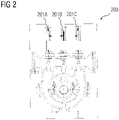
- FIG 2 illustrates a sectional view of a multi vale arrangement 200 of a steam turbine, of the state of the art.
- the multi-valve arrangement comprises valves 201A-201C operated in concert with one another to control steam inlet flow in the steam turbine.
- a single valve arrangement shown in FIG 1 or a multi-valve arrangement shown in FIG 2 is configured in a steam turbine.
- inlet casings of either single valve or multi-valve are procured as per order entry, from vendors, and then machined in-house or sourced back to vendors depending on factory loading.
- a single valve arrangement is required for mechanical drive applications whereas a multi-valve arrangement is required for turbogenerator set applications.
- a single valve arrangement is also preferred by customers in low capital investment market where customers prefer to run the turbine on single load-point for most parts of the season and will use the hand-valves when an increased power demand is there for short term durations during the season.
- inlet casings are one of the longest lead items in an order, their sourcing and machining results in an increase in overall delivery time of the turbine.
- Document US 6 302 644 B1 describes in figs. 1 and 2 a casing 1 for a steam turbine as a fluid power equipment.
- the steam turbine in fig. 1 has a control stage and the steam turbine in fig. 2 has no control stage and has a different interior design of the casing.
- the casing 1 comprises chambers 15, 16, capable of controlling a fluid flowing through the steam turbine in communication with a valve arrangement 7.
- the chambers 15 and 16 are separated by two intermediate walls 17, 18 in such a way that the chamber 15 forms a larger sector and therefore a larger passage area for the fresh steam than the chamber 16.
- Control valve 8 opens into the chamber 15 and control valve 9 into the chamber 16.
- the intermediate walls are removed in fig. 2 and there is only one chamber 19 left to which the steam is fed via both valves 8, 9.
- Document US 2015/0252681 A1 describes a modular steam turbine casing with an inner shell 110, comprising at least two chambers 130, 155. There are elements 175, 176 or 180 which can be machined to alter the number of chambers.
- Document DE 44 25 352 A1 describes a steam turbine casing 1a, 1b with a plurality of chambers 3a, 3b, wherein according to requirements wall elements 4 may be removed.
- Document DE 197 08 273 C1 describes a steam turbine casing 1 with a plurality of chambers 12, 15. There is also mentioned an intermediate wall 17, which is machinable in accordance with respective requirements for steam injection ZD or extraction AD, so that the number of chambers 12, 15 is altered.
- the casing arrangement disclosed in the present invention achieves the aforementioned object, in that the casing arrangement provides for one or more elements to be machined out easily based on valve arrangement configuration requirements.
- a casing for a steam turbine to control flow of fluid into the steam turbine.
- fluid power equipment refers to a steam turbine.
- casing refers to an enclosure capable of housing rotors, blades there-within and controlling flow of the fluid in the fluid power equipment.
- valve arrangement refers to control valve arrangement controlling flow of the fluid through the steam turbine.
- the valve arrangement is a single valve arrangement having up to three hand valves and a governing valve or a control valve.
- the governing valve or the control valve is actuator driven and each of the hand valves are operated manually, to control load points in a steam turbine, that is, flow of the steam.
- the valve arrangement is a multi-valve arrangement having up to three valves that are operated in concert to control load points in a steam turbine, that is, flow of the steam and are controlled by actuators.
- the casing also includes machineable elements which when selectively machined from the casing alter a number of the chambers there-within resulting in multiple chamber arrangements thereby, allowing multiple solutions, that is, multiple valve arrangements to be adapted to, with flexibility.
- machineable refers to an arrangement permitting removal of a material, for example, cutting of a metal.
- the elements refer to one or more parts of the casing.
- the elements comprise, for example, walls such as inner walls, outer walls, partitioning walls that form chambers within the casing.
- the elements also include physical dimensions of the walls such as a thickness of a wall, a height of the wall, etc.
- the elements also include holes punched through the walls of the casing for establishing fluid communication between a space enclosed within a chamber of the casing and a space outside the chamber, that is, in the remainder of the casing in a downstream direction of the fluid flow. The machineable walls when machined increase or decrease the number of chambers within the casing.
- the machineable elements are selectively machined from the casing based on a valve arrangement to be accommodated in the fluid power equipment, based on application requirements.
- the number of chambers can vary from about three to at least five depending on the amount of flow which needs to be admitted in the turbine or the type of valve control required.
- the machineable elements are machined so as to form four chambers.
- the machineable elements are machined so as to form three chambers in the casing.
- the casing has six chambers by default. Without machining any machineable elements, the casing's upper half can be used for a single valve arrangement having four valves. With machining only one of the machineable elements, the casing's upper half can be used for a multi-valve arrangement having three valves.
- the casing is configurable to suit multiple load point requirements of a fluid power equipment.
- the casing provided contains at least one hole and at least five chambers.
- the chambers are configured to be reduced in number by machining one or more elements of the casing thereby, combining the chambers, based on the valve arrangement to be accommodated in the fluid power equipment.
- holes are machined, that is, punched through a top wall of the casing such that the total number of holes is equal to the number of valves for the valve arrangement being accommodated. The valves are then assembled through these holes.
- one or more physical dimensions of the machineable elements of the casing are configured based on one or more fluid dynamics parameters associated with a fluid used in the fluid power equipment.
- the fluid dynamics parameters comprise, for example, a pressure of the fluid, a velocity of the fluid, a temperature of the fluid, a volumetric flow of the fluid, etc.
- valve-chest steam in the chambers that are in fluid communication with the valve arrangement, designated as valve-chest, will be used to feed the steam in the downstream section of the casing through a control section, for example, a nozzle-plate.
- An amount of steam to be admitted in a turbine is an outcome of a thermodynamic behavior of the turbine which is governed by steam characteristics comprising, for example, a steam velocity, a steam pressure, a steam temperature, etc.
- the casing disclosed herein allows accommodation of nozzles in the nozzle-plate to be positioned anywhere along a diameter of the chambers in the valve-chest.
- the design of the casing with its chambers and flexible control section geometry achieved via the nozzle plate positioning provides freedom of configuring an optimized turbine using a single common casing and eliminating the need to have separate variants to handle different thermodynamic load cases based on application requirements.
- the casing disclosed herein comprises an inflow member in fluid communication with one or more of the chambers and configurable to receive a fluid inflow into the casing.
- the inflow member is positioned so as to lead the fluid inflow into the chamber stretching across upper and lower halves of the casing.
- the casing disclosed herein is configurable to receive fluid inflow at least from each of opposing sides of the casing thereby, being effectively suited for a variety of customer requirements and installations.
- the casing when configured for a single valve arrangement can receive steam inlet flow from a bottom right side of the casing via the inflow member, a top right side of the casing, or a top left side of the casing.
- the casing when configured for a multi-valve arrangement can receive steam inlet flow from a top right side of the casing or a top left side of the casing.
- the casing disclosed herein enables significant reduction in inventory management time and effort because by procuring a single casing the requirements of single and multi-valve arrangements can be easily accommodated. This also leads to reduction in overall turbine costs and delivery time required per order. Moreover, flexibility of incorporating steam inlet entry for single valve arrangement from top left, from top right, or from bottom left increases customer base that can be catered to with minimal changes in the casing.
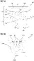
- FIGS 3A-3C illustrate sectional perspective views of a casing 300 having machineable walls 303 and 304, according to an embodiment of the present invention.
- FIG 3A illustrates a casing 300 configurable based on a single or a multi-valve arrangement to be accommodated in a fluid power equipment for which the casing is to be used.
- the casing 300 is provided by default and comprises about five chambers C1-C5.
- the chambers C1-C5 are configured to be reduced in number by machining one or more walls 303, 304, 305, etc., along orthogonal axes A-A' and B-B' passing centrally through the casing 300 thereby, combining one or more of the chambers C1-C5, based on the valve arrangement to be accommodated.
- the chambers C1 and C2 have a machineable wall 303 there-between.
- the chambers C3 and C4 have a machineable wall 305 there-between.
- the chambers C4 and C5 have a machineable wall 304 there-between.
- the chambers C1, C2, and C3 are positioned entirely in an upper half H1 of the casing 300.
- the chamber C4 is positioned entirely in a lower half H2 of the casing 300.
- the chamber C5 is positioned so as to stretch through the upper half H1 and the lower half H2 of the casing 300.
- the casing 300 may also have one or more holes 306 by default providing a fluid communication passage into the chambers C3 and/or C5.
- the casing 300 comprises an inflow member 307 in fluid communication with the chamber C5.
- the inflow member 307 is positioned in the lower half H2 to allow fluid inlet from bottom right of the casing 300.
- the casing 300 may comprise a sixth chamber C6 (not shown) formed by splitting the chamber C5 into two chambers by having a machineable wall (not shown) positioned along the horizontal axis A-A' corresponding to the position of the machineable wall 305.
- This arrangement allows the casing 300 to suit applications having a requirement for a low steam volume wherein, the chambers C1, C2, C3, and the sixth chamber (not shown) formed by splitting the chamber C5, that are lying in the upper half H1 of the casing 300 are put to use.
- the lower half H2 of the casing 300 remains unused.
- the machineable wall 303 can be machined from the casing 300 based on the valve arrangement to be accommodated.
- FIG 3B illustrates a casing 300 configured to accommodate a single valve arrangement. Therefore, the wall 304 shown in FIG 3A is machined out from the casing 300 thereby, creating chambers 300A, 300B, 300C, and 300D in the casing 300.
- the chambers 300A, 300B, and 300C each accommodate a hand valve of the single valve arrangement therein for controlling the load points during operation of a steam turbine in which the casing 300 is to be used.
- the chamber 300D accommodates a governing valve (not shown) therein inserted into the casing 300 which is mounted at an inlet flange (not shown) of the casing 300.
- One of the hand valves is inserted through the other hole 306 so as to be in fluid communication with the chamber 300C.
- Additional holes 301 are also machined from the casing 300 through which the hand valves are then inserted and installed in the casing 300 so as to be in fluid communication with the chambers 300A and 300B.
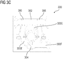
- FIG 3C illustrates a casing 300 configured to accommodate a multi-valve arrangement. Therefore, the walls 303 and 305 are machined out from the casing 300 thereby creating chambers 300E, 300F, and 300G in the casing 300.
- the chambers 300E, 300F, and 300G each accommodate a valve of the multi-valve arrangement therein for controlling the load points during operation of a steam turbine in which the casing 300 is to be used.
- a first valve and a third valve of the multi-valve arrangement are inserted into the casing 300 through holes 306 so as to be in fluid communication with the chambers 300E and 300F respectively.
- a hole 302 is machined from the casing 300 so as to provide fluid communication between a second valve of the multi-valve arrangement and the chamber 300G.
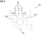
- FIG 4 illustrates a sectional elevation view of the casing 300 shown in FIG 3B accommodating a single valve arrangement 400, according to an embodiment of the present invention.
- the casing 300 post machining has chambers 300A, 300B, 300C, and 300D.
- the hand valves 401 of the single valve arrangement 400 are each in fluid communication with the space defined by inner walls of the chambers 300A, 300B, and 300C respectively.
- a governing valve (not shown) is in fluid communication with the space defined by inner walls of the chamber 300D.
- FIG 5 illustrates a sectional elevation view of the casing 300 shown in FIG 3C accommodating a multi-valve arrangement 500, according to an embodiment of the present invention.
- the casing 300 post machining has chambers 300E, 300F, and 300G.
- the valves 501 of the multi-valve arrangement 500 are each in fluid communication with the space defined by inner walls of the chambers 300E, 300F, and 300G respectively.
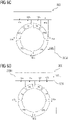
- FIG 6A-6E illustrate various steam inlet flow arrangements achieved using the casing 300 shown in FIGS 3A-3C .
- FIGS 6A-6D illustrate the casing 300 machined to suit a single valve arrangement 400 shown in FIG 4 .
- the casing 300 allows entry of the steam from bottom right side 300J of the casing 300 allowing about 65% of the steam in the chamber 300D, 10% of the steam in each of the chambers 300A and 300B shown in FIG 3B , and 15% of the steam in the chamber 300C shown in FIG 3B upon operation of the hand valves 401 shown in FIG 4 .
- the casing 300 allows entry of the steam from top right side 3001 of the casing 300 allowing about 65% of the steam in the chamber 300D, 10% of the steam in each of the chambers 300A and 300B, and 15% of the steam in the chamber 300C upon operation of the hand valves 401.
- the casing 300 is machined so as to allow entry of the steam from bottom right side 300J of the casing 300 thereby, allowing 100% steam to enter into the chamber 300D further being split into about 50% in each of the two halves within the chamber 300D i.e. upper half and lower half.
- 10% of the steam enters the chamber 300B from the chamber 300C which is in communication with the chamber 300D through hand-valve 401.
- 10% of the steam enters the chamber 300A upon operation of the hand valves 401.
- one or more machineable elements such as the machineable walls 304 and 305, of the casing 300 between the chambers 300D and 300C are machined to allow the chambers 300D and 300C to be in fluid communication with one another.
- the single valve arrangement 400 works with three chambers 300A, 300B, and the chamber formed by combining the chambers 300C and 300D.
- the casing 300 is machined so as to allow entry of the steam from top right side 3001 of the casing 300 thereby, allowing 40% of the steam to enter into the chamber 300D, 10% of the steam into the chamber 300A, 10% of the steam into the chamber 300B, and 40% of the steam into chamber 300C upon operation of the hand valves 401.
- one or more machineable elements of the casing 300 between the chambers 300D and 300C are machined so as to allow approximately equal area within the chambers 300C and 300D.
- FIGS 6E illustrates the casing 300 machined to suit a multi-valve arrangement 500 shown in FIG 5 .
- the casing 300 is machined so as to allow entry of the steam from top right side 3001 of the casing 300 allowing 40% of the steam to flow into the chamber 300F, 20% of the steam to flow into the chamber 300G and 40% of the steam to flow into the chamber 300E upon operation of the valves 501.
- the casing 300 shown in FIGS 6A-6E can be machined to accept the steam flow entry thorough the top left side 300H of the casing 300 for both single valve arrangement 400 as well as multi-valve arrangement 500.
Landscapes
- Engineering & Computer Science (AREA)
- General Engineering & Computer Science (AREA)
- Mechanical Engineering (AREA)
- Control Of Turbines (AREA)
- Valve Housings (AREA)
Description
- The present invention relates to a casing arrangement for a steam turbine. More particularly the present invention relates to a customizable casing arrangement customized for accommodating a governing valve or control valve of either single valve design or multi-valve design into the fluid power equipment, which control flow of the fluid, such as, steam into the steam turbine.
- Fluid power equipment, such as, steam turbines employed in industrial setups typically, employ valve arrangements, in order to regulate flow of steam according to load changes or to stop the flow of steam altogether. Such valve arrangements typically constitute arrangements controlling an inlet of the industrial steam via a single governing valve or a series of governing valves working in concert also known as multi-valve arrangements. Based on the valve arrangement and an inlet size of a steam turbine, the casing designs vary. For example, up to four variants may have to be designed. This leads to a longer delivery time, a higher inventory cost, a higher pattern cost, and an increased engineering effort.
-
FIG 1 illustrates a sectional view of asingle valve arrangement 100 of a steam turbine, of the state of the art, as mentioned above. Thesingle valve arrangement 100 of the state of the art, is bulkier compared to a multi-valve arrangement, as it requires additional space to accumulate volumetric flow of the steam required by the turbine. Thesingle valve arrangement 100 comprisesvalves inner chamber 102. Moreover, in asingle valve arrangement 100, thesteam inlet flow 103 has to be maintained from one side only, for example, right hand side. Thissingle valve arrangement 100 suits the customers who generally have a fixed direction of steam inflow. However, thissingle valve arrangement 100 poses limitations for those customers who need flexibility in the design due to the steam inlet being in the opposite direction to that of theinlet flow 103 of thesingle vale arrangement 100 of the state of the art. This leads to unnecessary loss of customer orders. -
FIG 2 illustrates a sectional view of amulti vale arrangement 200 of a steam turbine, of the state of the art. The multi-valve arrangement comprisesvalves 201A-201C operated in concert with one another to control steam inlet flow in the steam turbine. According to the load control requirements of a customer, a single valve arrangement shown inFIG 1 or a multi-valve arrangement shown inFIG 2 is configured in a steam turbine. - At present, original equipment manufacturers (OEMs) do not maintain a significant inventory due to high number of variants required in the casing design. Typically, inlet casings of either single valve or multi-valve are procured as per order entry, from vendors, and then machined in-house or sourced back to vendors depending on factory loading. Typically, a single valve arrangement is required for mechanical drive applications whereas a multi-valve arrangement is required for turbogenerator set applications. Additionally, a single valve arrangement is also preferred by customers in low capital investment market where customers prefer to run the turbine on single load-point for most parts of the season and will use the hand-valves when an increased power demand is there for short term durations during the season. As inlet casings are one of the longest lead items in an order, their sourcing and machining results in an increase in overall delivery time of the turbine.
- Document
US 6 302 644 B1 describes infigs. 1 and2 a casing 1 for a steam turbine as a fluid power equipment. The steam turbine infig. 1 has a control stage and the steam turbine infig. 2 has no control stage and has a different interior design of the casing. The casing 1 compriseschambers 15, 16, capable of controlling a fluid flowing through the steam turbine in communication with a valve arrangement 7. Infig. 1 thechambers 15 and 16 are separated by two intermediate walls 17, 18 in such a way that thechamber 15 forms a larger sector and therefore a larger passage area for the fresh steam than the chamber 16. Control valve 8 opens into thechamber 15 and control valve 9 into the chamber 16. The intermediate walls are removed infig. 2 and there is only one chamber 19 left to which the steam is fed via both valves 8, 9. - Document
US 2015/0252681 A1 describes a modular steam turbine casing with an inner shell 110, comprising at least two chambers 130, 155. There are elements 175, 176 or 180 which can be machined to alter the number of chambers. - Document
DE 44 25 352 A1 describes a steam turbine casing 1a, 1b with a plurality of chambers 3a, 3b, wherein according to requirements wall elements 4 may be removed. - Document
DE 197 08 273 C1 describes a steam turbine casing 1 with a plurality ofchambers 12, 15. There is also mentioned an intermediate wall 17, which is machinable in accordance with respective requirements for steam injection ZD or extraction AD, so that the number ofchambers 12, 15 is altered. - Therefore, it is an object of the present invention to provide a casing arrangement to be employed, for example, in a fluid power equipment of the aforementioned kind, wherein the casing arrangement is simple in design, is cost effective, and is able to accommodate different variants of the valve arrangements including single valve and multi-valve arrangements with minimal alterations.
- The casing arrangement disclosed in the present invention achieves the aforementioned object, in that the casing arrangement provides for one or more elements to be machined out easily based on valve arrangement configuration requirements.
- Disclosed herein is a casing for a steam turbine, according to claim 1, to control flow of fluid into the steam turbine. As used herein, "fluid power equipment" refers to a steam turbine. The term "casing" refers to an enclosure capable of housing rotors, blades there-within and controlling flow of the fluid in the fluid power equipment.
- The casing disclosed herein comprises chambers within the casing, capable of controlling a fluid flowing through the fluid power equipment in communication with a valve arrangement, typically referred to as valve-chest. As used herein, "valve arrangement" refers to control valve arrangement controlling flow of the fluid through the steam turbine. According to one aspect, which is not claimed, the valve arrangement is a single valve arrangement having up to three hand valves and a governing valve or a control valve. The governing valve or the control valve is actuator driven and each of the hand valves are operated manually, to control load points in a steam turbine, that is, flow of the steam. According to another aspect, which is not claimed, the valve arrangement is a multi-valve arrangement having up to three valves that are operated in concert to control load points in a steam turbine, that is, flow of the steam and are controlled by actuators. Advantageously, there are at least five chambers available in the casing. There may be more than five chambers based on customization requirements to be made. The casing also includes machineable elements which when selectively machined from the casing alter a number of the chambers there-within resulting in multiple chamber arrangements thereby, allowing multiple solutions, that is, multiple valve arrangements to be adapted to, with flexibility. As used herein, the term "machineable" refers to an arrangement permitting removal of a material, for example, cutting of a metal. Also used herein, "elements" refer to one or more parts of the casing. According to one aspect of the present invention, the elements comprise, for example, walls such as inner walls, outer walls, partitioning walls that form chambers within the casing. According to another aspect, which is not claimed, the elements also include physical dimensions of the walls such as a thickness of a wall, a height of the wall, etc. According to yet another aspect, which is not claimed, the elements also include holes punched through the walls of the casing for establishing fluid communication between a space enclosed within a chamber of the casing and a space outside the chamber, that is, in the remainder of the casing in a downstream direction of the fluid flow. The machineable walls when machined increase or decrease the number of chambers within the casing. Advantageously, the machineable elements are selectively machined from the casing based on a valve arrangement to be accommodated in the fluid power equipment, based on application requirements. Advantageously, the number of chambers can vary from about three to at least five depending on the amount of flow which needs to be admitted in the turbine or the type of valve control required. For example, when four valves including three hand valves and a governing valve of a single valve arrangement is to be accommodated in the fluid power equipment, the machineable elements are machined so as to form four chambers. Similarly, when three valves of a multi-valve arrangement are to be accommodated in the fluid power equipment, the machineable elements are machined so as to form three chambers in the casing. Similarly, in cases of a low steam volume requirement, only an upper half of the casing can be used. In this scenario, the casing has six chambers by default. Without machining any machineable elements, the casing's upper half can be used for a single valve arrangement having four valves. With machining only one of the machineable elements, the casing's upper half can be used for a multi-valve arrangement having three valves. Thus, the casing is configurable to suit multiple load point requirements of a fluid power equipment.
- According to one aspect, which is not claimed, the casing provided contains at least one hole and at least five chambers. The chambers are configured to be reduced in number by machining one or more elements of the casing thereby, combining the chambers, based on the valve arrangement to be accommodated in the fluid power equipment.
- Advantageously, based on the number of chambers formed post machining of the elements, holes are machined, that is, punched through a top wall of the casing such that the total number of holes is equal to the number of valves for the valve arrangement being accommodated. The valves are then assembled through these holes.
- Advantageously, one or more physical dimensions of the machineable elements of the casing are configured based on one or more fluid dynamics parameters associated with a fluid used in the fluid power equipment. The fluid dynamics parameters comprise, for example, a pressure of the fluid, a velocity of the fluid, a temperature of the fluid, a volumetric flow of the fluid, etc.
- Typically, steam in the chambers that are in fluid communication with the valve arrangement, designated as valve-chest, will be used to feed the steam in the downstream section of the casing through a control section, for example, a nozzle-plate. An amount of steam to be admitted in a turbine is an outcome of a thermodynamic behavior of the turbine which is governed by steam characteristics comprising, for example, a steam velocity, a steam pressure, a steam temperature, etc. According to yet another aspect, which is not claimed, the casing disclosed herein allows accommodation of nozzles in the nozzle-plate to be positioned anywhere along a diameter of the chambers in the valve-chest. Advantageously, the design of the casing with its chambers and flexible control section geometry achieved via the nozzle plate positioning provides freedom of configuring an optimized turbine using a single common casing and eliminating the need to have separate variants to handle different thermodynamic load cases based on application requirements.
- The casing disclosed herein comprises an inflow member in fluid communication with one or more of the chambers and configurable to receive a fluid inflow into the casing. Advantageously, the inflow member is positioned so as to lead the fluid inflow into the chamber stretching across upper and lower halves of the casing. Advantageously, the casing disclosed herein is configurable to receive fluid inflow at least from each of opposing sides of the casing thereby, being effectively suited for a variety of customer requirements and installations. The casing when configured for a single valve arrangement can receive steam inlet flow from a bottom right side of the casing via the inflow member, a top right side of the casing, or a top left side of the casing. The casing when configured for a multi-valve arrangement can receive steam inlet flow from a top right side of the casing or a top left side of the casing.
- Thus, the casing disclosed herein enables significant reduction in inventory management time and effort because by procuring a single casing the requirements of single and multi-valve arrangements can be easily accommodated. This also leads to reduction in overall turbine costs and delivery time required per order. Moreover, flexibility of incorporating steam inlet entry for single valve arrangement from top left, from top right, or from bottom left increases customer base that can be catered to with minimal changes in the casing.
- The above-mentioned and other features of the invention will now be addressed with reference to the accompanying drawings of the present invention. The illustrated embodiments are intended to illustrate, but not limit the invention.
- The present invention is further described hereinafter with reference to illustrated embodiments shown in the accompanying drawings, in which:
- FIG 1
- illustrates a sectional view of a single valve arrangement of a steam turbine, of the state of the art.
- FIG 2
- illustrates a sectional view of a multi vale arrangement of a steam turbine, of the state of the art.
- FIGS 3A-3C
- illustrate sectional perspective views of a casing having machineable walls, according to an embodiment of the present invention.
- FIG 4
- illustrates a sectional elevation view of the casing shown in
FIG 3B accommodating a single valve arrangement, according to an embodiment of the present invention. - FIG 5
- illustrates a sectional elevation view of the casing shown in
FIG 3C accommodating a multi-valve arrangement, according to an embodiment of the present invention. - FIG 6A-6E
- illustrate various steam inlet flow arrangements achieved using the casing shown in
FIGS 3A-3C . - Various embodiments are described with reference to the drawings, wherein like reference numerals are used to refer to like elements throughout. In the following description, for the purpose of explanation, numerous specific details are set forth in order to provide thorough understanding of one or more embodiments. It may be evident that such embodiments may be practiced without these specific details.
-
FIGS 3A-3C illustrate sectional perspective views of acasing 300 havingmachineable walls -
FIG 3A illustrates acasing 300 configurable based on a single or a multi-valve arrangement to be accommodated in a fluid power equipment for which the casing is to be used. Thecasing 300 is provided by default and comprises about five chambers C1-C5. The chambers C1-C5 are configured to be reduced in number by machining one ormore walls casing 300 thereby, combining one or more of the chambers C1-C5, based on the valve arrangement to be accommodated. The chambers C1 and C2 have amachineable wall 303 there-between. The chambers C3 and C4 have amachineable wall 305 there-between. The chambers C4 and C5 have amachineable wall 304 there-between. The chambers C1, C2, and C3 are positioned entirely in an upper half H1 of thecasing 300. The chamber C4 is positioned entirely in a lower half H2 of thecasing 300. The chamber C5 is positioned so as to stretch through the upper half H1 and the lower half H2 of thecasing 300. Thecasing 300 may also have one ormore holes 306 by default providing a fluid communication passage into the chambers C3 and/or C5. Thecasing 300 comprises aninflow member 307 in fluid communication with the chamber C5. Theinflow member 307 is positioned in the lower half H2 to allow fluid inlet from bottom right of thecasing 300. - Alternatively, the
casing 300 may comprise a sixth chamber C6 (not shown) formed by splitting the chamber C5 into two chambers by having a machineable wall (not shown) positioned along the horizontal axis A-A' corresponding to the position of themachineable wall 305. This arrangement allows thecasing 300 to suit applications having a requirement for a low steam volume wherein, the chambers C1, C2, C3, and the sixth chamber (not shown) formed by splitting the chamber C5, that are lying in the upper half H1 of thecasing 300 are put to use. The lower half H2 of thecasing 300 remains unused. In this arrangement, themachineable wall 303 can be machined from thecasing 300 based on the valve arrangement to be accommodated. -
FIG 3B illustrates acasing 300 configured to accommodate a single valve arrangement. Therefore, thewall 304 shown inFIG 3A is machined out from thecasing 300 thereby, creatingchambers casing 300. Thechambers casing 300 is to be used. Thechamber 300D accommodates a governing valve (not shown) therein inserted into thecasing 300 which is mounted at an inlet flange (not shown) of thecasing 300. One of the hand valves is inserted through theother hole 306 so as to be in fluid communication with thechamber 300C.Additional holes 301 are also machined from thecasing 300 through which the hand valves are then inserted and installed in thecasing 300 so as to be in fluid communication with thechambers -
FIG 3C illustrates acasing 300 configured to accommodate a multi-valve arrangement. Therefore, thewalls casing 300 thereby creatingchambers casing 300. Thechambers casing 300 is to be used. A first valve and a third valve of the multi-valve arrangement are inserted into thecasing 300 throughholes 306 so as to be in fluid communication with thechambers hole 302 is machined from thecasing 300 so as to provide fluid communication between a second valve of the multi-valve arrangement and thechamber 300G. -
FIG 4 illustrates a sectional elevation view of thecasing 300 shown inFIG 3B accommodating asingle valve arrangement 400, according to an embodiment of the present invention. Thecasing 300 post machining haschambers hand valves 401 of thesingle valve arrangement 400 are each in fluid communication with the space defined by inner walls of thechambers chamber 300D. -
FIG 5 illustrates a sectional elevation view of thecasing 300 shown inFIG 3C accommodating amulti-valve arrangement 500, according to an embodiment of the present invention. Thecasing 300 post machining haschambers valves 501 of themulti-valve arrangement 500 are each in fluid communication with the space defined by inner walls of thechambers -
FIG 6A-6E illustrate various steam inlet flow arrangements achieved using thecasing 300 shown inFIGS 3A-3C .FIGS 6A-6D illustrate thecasing 300 machined to suit asingle valve arrangement 400 shown inFIG 4 . - As shown in
FIG 6A , thecasing 300 allows entry of the steam from bottomright side 300J of thecasing 300 allowing about 65% of the steam in thechamber chambers FIG 3B , and 15% of the steam in thechamber 300C shown inFIG 3B upon operation of thehand valves 401 shown inFIG 4 . - As shown in
FIG 6B , thecasing 300 allows entry of the steam from topright side 3001 of thecasing 300 allowing about 65% of the steam in thechamber chambers chamber 300C upon operation of thehand valves 401. - As shown in
FIG 6C , thecasing 300 is machined so as to allow entry of the steam from bottomright side 300J of thecasing 300 thereby, allowing 100% steam to enter into thechamber 300D further being split into about 50% in each of the two halves within thechamber 300D i.e. upper half and lower half. Out of which, 10% of the steam enters thechamber 300B from thechamber 300C which is in communication with thechamber 300D through hand-valve 401. Also, 10% of the steam enters thechamber 300A upon operation of thehand valves 401. In this arrangement, one or more machineable elements, such as themachineable walls casing 300 between thechambers chambers casing 300 shown inFIG 6C , thesingle valve arrangement 400 works with threechambers chambers - As shown in
FIG 6D , thecasing 300 is machined so as to allow entry of the steam from topright side 3001 of thecasing 300 thereby, allowing 40% of the steam to enter into thechamber chamber chamber chamber 300C upon operation of thehand valves 401. In this arrangement, one or more machineable elements of thecasing 300 between thechambers chambers -
FIGS 6E illustrates thecasing 300 machined to suit amulti-valve arrangement 500 shown inFIG 5 . As shown inFIG 6E , thecasing 300 is machined so as to allow entry of the steam from topright side 3001 of thecasing 300 allowing 40% of the steam to flow into thechamber chamber chamber 300E upon operation of thevalves 501. - The
casing 300 shown inFIGS 6A-6E can be machined to accept the steam flow entry thorough the topleft side 300H of thecasing 300 for bothsingle valve arrangement 400 as well asmulti-valve arrangement 500. - The foregoing examples have been provided merely for the purpose of explanation and are in no way to be construed as limiting of the present invention disclosed herein. While the invention has been described with reference to various embodiments, it is understood that the words, which have been used herein, are words of description and illustration, rather than words of limitation. Further, although the invention has been described herein with reference to particular means, materials, and embodiments, the invention is not intended to be limited to the particulars disclosed herein; rather, the invention extends to all functionally equivalent structures, methods and uses, such as are within the scope of the appended claims. Those skilled in the art, having the benefit of the teachings of this specification, may affect numerous modifications thereto and changes may be made without departing from the scope of the invention in its aspects.
-
- 100 single valve arrangement of state of art
- 101A, 101B, 101C valves of the single valve arrangement of state of art
- 102 inner chamber
- 103 fluid/steam inlet flow
- 200 multi valve arrangement of state of art
- 201A, 201B, 201C valves of the multi valve arrangement of state of art
- 300 casing
- 300A-300G chambers
- 300A-300D chambers for accommodating single valve arrangement
- 300E-300G chambers for accommodating multi valve arrangement
- 300H top left side of the casing
- 3001 top right side of the casing
- 300J bottom right side of the casing
- 301, 302, 306 holes
- 303, 304, 305 machineable walls
- 307 inflow member at bottom right side of the casing
- A - A' and B - B' orthogonal axes centrally passing through casing
- C1-C5 chambers provided by default
- H1 upper half of the casing
- H2 lower half of the casing
- 400 single valve arrangement
- 401 valves
- 500 multi valve arrangement
- 501 valves
Claims (5)
- A casing (300) for a steam turbine, the casing (300) comprising:- a plurality of chambers (C1-C5) inside the casing (300) capable of controlling a fluid flowing through the steam turbine in communication with a valve arrangement (400, 500); and characterized by:- machineable elements (301, 302, 303, 304, 305) configured to be removed, for enabling the accommodation of single valve (400) and multi-valve arrangements (500), said machineable elements (301, 302, 303, 304, 305) when selectively machined from the casing (300) decrease the number of the plurality of chambers (C1-C6) inside said casing (300),wherein after removing the machinable elements(301, 302, 303, 304, 305), the plurality of chambers (C1-C5) each accommodate a valve of the single valve (400) or multi-valve arrangement (500) for controlling the load points during operation of the steam turbine.
- The casing (300) according to the claim 1, wherein the one or more of the machineable elements (301, 302, 303, 304, 305) are selectively machined from the casing (300) based on the single valve (400) and multi-valve arrangement (500) to be accommodated in the steam turbine.
- The casing (300) according to any one the previous claims, wherein one or more physical dimensions of the machineable elements (301, 302, 303, 304, 305) are configured based on one or more fluid dynamics parameters associated with a fluid used in the steam turbine,
wherein the one or more fluid dynamics parameters is one of the following: a pressure of the fluid, a velocity of the fluid, a temperature of the fluid, a volumetric flow of the fluid. - The casing (300) according to any one of the previous claims, configured to receive fluid inflow at least from each of opposing sides (300H, 3001) of the casing (300), wherein the opposing sides (300H, 3001) of the casing (300) are a top left side of the casing (300H) and a top right side of the casing (300I).
- The casing (300) according to any one of the previous claims, comprising an inflow member (307) in fluid communication with one or more of the chambers (C1-C5) and configured to receive a fluid inflow into the casing (300).
Priority Applications (3)
| Application Number | Priority Date | Filing Date | Title |
|---|---|---|---|
| PL19177692.1T PL3744952T3 (en) | 2019-05-31 | 2019-05-31 | Casing arrangement for fluid power equipment |
| EP19177692.1A EP3744952B1 (en) | 2019-05-31 | 2019-05-31 | Casing arrangement for fluid power equipment |
| PCT/EP2020/065020 WO2020239997A1 (en) | 2019-05-31 | 2020-05-29 | Customisable casing arrangement for steam turbine |
Applications Claiming Priority (1)
| Application Number | Priority Date | Filing Date | Title |
|---|---|---|---|
| EP19177692.1A EP3744952B1 (en) | 2019-05-31 | 2019-05-31 | Casing arrangement for fluid power equipment |
Publications (2)
| Publication Number | Publication Date |
|---|---|
| EP3744952A1 EP3744952A1 (en) | 2020-12-02 |
| EP3744952B1 true EP3744952B1 (en) | 2022-12-14 |
Family
ID=66685456
Family Applications (1)
| Application Number | Title | Priority Date | Filing Date |
|---|---|---|---|
| EP19177692.1A Active EP3744952B1 (en) | 2019-05-31 | 2019-05-31 | Casing arrangement for fluid power equipment |
Country Status (3)
| Country | Link |
|---|---|
| EP (1) | EP3744952B1 (en) |
| PL (1) | PL3744952T3 (en) |
| WO (1) | WO2020239997A1 (en) |
Family Cites Families (4)
| Publication number | Priority date | Publication date | Assignee | Title |
|---|---|---|---|---|
| DE4425352C2 (en) * | 1994-07-18 | 2001-10-11 | Abb Patent Gmbh | Steam turbine with a turbine housing manufactured in the casting process |
| DE19708273C1 (en) * | 1997-02-28 | 1998-04-30 | Siemens Ag | Industrial steam-turbine housing design |
| EP1026369B1 (en) * | 1999-02-04 | 2003-12-03 | ALSTOM (Switzerland) Ltd | Steam turbine |
| US20150252681A1 (en) * | 2014-03-05 | 2015-09-10 | General Electric Company | Modular turbomachine inner and outer casings with multi-stage steam extraction sites |
-
2019
- 2019-05-31 EP EP19177692.1A patent/EP3744952B1/en active Active
- 2019-05-31 PL PL19177692.1T patent/PL3744952T3/en unknown
-
2020
- 2020-05-29 WO PCT/EP2020/065020 patent/WO2020239997A1/en not_active Ceased
Also Published As
| Publication number | Publication date |
|---|---|
| EP3744952A1 (en) | 2020-12-02 |
| PL3744952T3 (en) | 2023-04-11 |
| WO2020239997A1 (en) | 2020-12-03 |
Similar Documents
| Publication | Publication Date | Title |
|---|---|---|
| EP3099939B1 (en) | Two-stage centrifugal pump | |
| US7174971B1 (en) | Clockwise or counterclockwise rotation control device of a pneumatic tool | |
| KR101747450B1 (en) | Two position three way valve | |
| JP2022093651A5 (en) | ||
| JP5978367B2 (en) | Model-based adaptive control method and system for multi-input multi-output plant | |
| CN114729707B (en) | Multiple control valve device | |
| EP2990654B1 (en) | Centrifugal compressor | |
| US20030078697A1 (en) | Device for controlling a hydraulic actuator | |
| KR101723251B1 (en) | Hydraulic system | |
| EP3828045A1 (en) | 3d printed manifold for a pneumatic control panel of a railway vehicle | |
| EP3744952A1 (en) | Casing arrangement for fluid power equipment | |
| ITFI20130208A1 (en) | "MULTISTAGE CENTRIFUGAL COMPRESSOR" | |
| EP1925863A1 (en) | Fluid controller | |
| JPS59120787A (en) | Hydraulic piston-cylinder machine | |
| EP2852734B1 (en) | Passive thermostatic valve | |
| EP3699466B1 (en) | Fluid valve system with modules and method of producing the same | |
| US11473554B2 (en) | Radial piston hydraulic motor and method for controlling radial piston hydraulic motor | |
| GB2400417A (en) | A radial piston motor having a free rotation valve | |
| CN102162551A (en) | Actuator, valve and method | |
| EP3296514B1 (en) | Fluidically controlled steam turbine inlet scroll | |
| EP3553286B1 (en) | Steam turbine, partition member, and method for operating steam turbine | |
| EP3869014B1 (en) | Valve drive device for a steam turbine system | |
| KR102312108B1 (en) | Coating device of 3 dimension structure including evacuated chamber with space partitionable pendulum movement reactor | |
| CN113202934A (en) | Valve, modular system for manufacturing a valve and method for manufacturing a valve | |
| KR102242216B1 (en) | Multistage trim for control valves |
Legal Events
| Date | Code | Title | Description |
|---|---|---|---|
| PUAI | Public reference made under article 153(3) epc to a published international application that has entered the european phase |
Free format text: ORIGINAL CODE: 0009012 |
|
| STAA | Information on the status of an ep patent application or granted ep patent |
Free format text: STATUS: THE APPLICATION HAS BEEN PUBLISHED |
|
| AK | Designated contracting states |
Kind code of ref document: A1 Designated state(s): AL AT BE BG CH CY CZ DE DK EE ES FI FR GB GR HR HU IE IS IT LI LT LU LV MC MK MT NL NO PL PT RO RS SE SI SK SM TR |
|
| AX | Request for extension of the european patent |
Extension state: BA ME |
|
| RAP1 | Party data changed (applicant data changed or rights of an application transferred) |
Owner name: SIEMENS ENERGY GLOBAL GMBH & CO. KG |
|
| STAA | Information on the status of an ep patent application or granted ep patent |
Free format text: STATUS: REQUEST FOR EXAMINATION WAS MADE |
|
| 17P | Request for examination filed |
Effective date: 20210527 |
|
| RBV | Designated contracting states (corrected) |
Designated state(s): AL AT BE BG CH CY CZ DE DK EE ES FI FR GB GR HR HU IE IS IT LI LT LU LV MC MK MT NL NO PL PT RO RS SE SI SK SM TR |
|
| REG | Reference to a national code |
Ref country code: DE Ref legal event code: R079 Ref document number: 602019023072 Country of ref document: DE Free format text: PREVIOUS MAIN CLASS: F01D0017180000 Ipc: F16K0011200000 |
|
| RIC1 | Information provided on ipc code assigned before grant |
Ipc: F01D 25/24 20060101ALI20220513BHEP Ipc: F01D 17/18 20060101ALI20220513BHEP Ipc: F16K 27/02 20060101ALI20220513BHEP Ipc: F16K 11/20 20060101AFI20220513BHEP |
|
| GRAP | Despatch of communication of intention to grant a patent |
Free format text: ORIGINAL CODE: EPIDOSNIGR1 |
|
| STAA | Information on the status of an ep patent application or granted ep patent |
Free format text: STATUS: GRANT OF PATENT IS INTENDED |
|
| INTG | Intention to grant announced |
Effective date: 20220629 |
|
| GRAS | Grant fee paid |
Free format text: ORIGINAL CODE: EPIDOSNIGR3 |
|
| GRAA | (expected) grant |
Free format text: ORIGINAL CODE: 0009210 |
|
| STAA | Information on the status of an ep patent application or granted ep patent |
Free format text: STATUS: THE PATENT HAS BEEN GRANTED |
|
| AK | Designated contracting states |
Kind code of ref document: B1 Designated state(s): AL AT BE BG CH CY CZ DE DK EE ES FI FR GB GR HR HU IE IS IT LI LT LU LV MC MK MT NL NO PL PT RO RS SE SI SK SM TR |
|
| REG | Reference to a national code |
Ref country code: GB Ref legal event code: FG4D |
|
| REG | Reference to a national code |
Ref country code: CH Ref legal event code: EP |
|
| REG | Reference to a national code |
Ref country code: DE Ref legal event code: R096 Ref document number: 602019023072 Country of ref document: DE |
|
| REG | Reference to a national code |
Ref country code: IE Ref legal event code: FG4D |
|
| REG | Reference to a national code |
Ref country code: AT Ref legal event code: REF Ref document number: 1537857 Country of ref document: AT Kind code of ref document: T Effective date: 20230115 |
|
| REG | Reference to a national code |
Ref country code: LT Ref legal event code: MG9D |
|
| REG | Reference to a national code |
Ref country code: NL Ref legal event code: MP Effective date: 20221214 |
|
| PG25 | Lapsed in a contracting state [announced via postgrant information from national office to epo] |
Ref country code: SE Free format text: LAPSE BECAUSE OF FAILURE TO SUBMIT A TRANSLATION OF THE DESCRIPTION OR TO PAY THE FEE WITHIN THE PRESCRIBED TIME-LIMIT Effective date: 20221214 Ref country code: NO Free format text: LAPSE BECAUSE OF FAILURE TO SUBMIT A TRANSLATION OF THE DESCRIPTION OR TO PAY THE FEE WITHIN THE PRESCRIBED TIME-LIMIT Effective date: 20230314 Ref country code: LT Free format text: LAPSE BECAUSE OF FAILURE TO SUBMIT A TRANSLATION OF THE DESCRIPTION OR TO PAY THE FEE WITHIN THE PRESCRIBED TIME-LIMIT Effective date: 20221214 Ref country code: FI Free format text: LAPSE BECAUSE OF FAILURE TO SUBMIT A TRANSLATION OF THE DESCRIPTION OR TO PAY THE FEE WITHIN THE PRESCRIBED TIME-LIMIT Effective date: 20221214 |
|
| REG | Reference to a national code |
Ref country code: AT Ref legal event code: MK05 Ref document number: 1537857 Country of ref document: AT Kind code of ref document: T Effective date: 20221214 |
|
| PG25 | Lapsed in a contracting state [announced via postgrant information from national office to epo] |
Ref country code: RS Free format text: LAPSE BECAUSE OF FAILURE TO SUBMIT A TRANSLATION OF THE DESCRIPTION OR TO PAY THE FEE WITHIN THE PRESCRIBED TIME-LIMIT Effective date: 20221214 Ref country code: LV Free format text: LAPSE BECAUSE OF FAILURE TO SUBMIT A TRANSLATION OF THE DESCRIPTION OR TO PAY THE FEE WITHIN THE PRESCRIBED TIME-LIMIT Effective date: 20221214 Ref country code: HR Free format text: LAPSE BECAUSE OF FAILURE TO SUBMIT A TRANSLATION OF THE DESCRIPTION OR TO PAY THE FEE WITHIN THE PRESCRIBED TIME-LIMIT Effective date: 20221214 Ref country code: GR Free format text: LAPSE BECAUSE OF FAILURE TO SUBMIT A TRANSLATION OF THE DESCRIPTION OR TO PAY THE FEE WITHIN THE PRESCRIBED TIME-LIMIT Effective date: 20230315 |
|
| PG25 | Lapsed in a contracting state [announced via postgrant information from national office to epo] |
Ref country code: NL Free format text: LAPSE BECAUSE OF FAILURE TO SUBMIT A TRANSLATION OF THE DESCRIPTION OR TO PAY THE FEE WITHIN THE PRESCRIBED TIME-LIMIT Effective date: 20221214 |
|
| PG25 | Lapsed in a contracting state [announced via postgrant information from national office to epo] |
Ref country code: SM Free format text: LAPSE BECAUSE OF FAILURE TO SUBMIT A TRANSLATION OF THE DESCRIPTION OR TO PAY THE FEE WITHIN THE PRESCRIBED TIME-LIMIT Effective date: 20221214 Ref country code: RO Free format text: LAPSE BECAUSE OF FAILURE TO SUBMIT A TRANSLATION OF THE DESCRIPTION OR TO PAY THE FEE WITHIN THE PRESCRIBED TIME-LIMIT Effective date: 20221214 Ref country code: PT Free format text: LAPSE BECAUSE OF FAILURE TO SUBMIT A TRANSLATION OF THE DESCRIPTION OR TO PAY THE FEE WITHIN THE PRESCRIBED TIME-LIMIT Effective date: 20230414 Ref country code: ES Free format text: LAPSE BECAUSE OF FAILURE TO SUBMIT A TRANSLATION OF THE DESCRIPTION OR TO PAY THE FEE WITHIN THE PRESCRIBED TIME-LIMIT Effective date: 20221214 Ref country code: EE Free format text: LAPSE BECAUSE OF FAILURE TO SUBMIT A TRANSLATION OF THE DESCRIPTION OR TO PAY THE FEE WITHIN THE PRESCRIBED TIME-LIMIT Effective date: 20221214 Ref country code: AT Free format text: LAPSE BECAUSE OF FAILURE TO SUBMIT A TRANSLATION OF THE DESCRIPTION OR TO PAY THE FEE WITHIN THE PRESCRIBED TIME-LIMIT Effective date: 20221214 |
|
| PG25 | Lapsed in a contracting state [announced via postgrant information from national office to epo] |
Ref country code: SK Free format text: LAPSE BECAUSE OF FAILURE TO SUBMIT A TRANSLATION OF THE DESCRIPTION OR TO PAY THE FEE WITHIN THE PRESCRIBED TIME-LIMIT Effective date: 20221214 Ref country code: IS Free format text: LAPSE BECAUSE OF FAILURE TO SUBMIT A TRANSLATION OF THE DESCRIPTION OR TO PAY THE FEE WITHIN THE PRESCRIBED TIME-LIMIT Effective date: 20230414 Ref country code: AL Free format text: LAPSE BECAUSE OF FAILURE TO SUBMIT A TRANSLATION OF THE DESCRIPTION OR TO PAY THE FEE WITHIN THE PRESCRIBED TIME-LIMIT Effective date: 20221214 |
|
| REG | Reference to a national code |
Ref country code: DE Ref legal event code: R097 Ref document number: 602019023072 Country of ref document: DE |
|
| PLBE | No opposition filed within time limit |
Free format text: ORIGINAL CODE: 0009261 |
|
| STAA | Information on the status of an ep patent application or granted ep patent |
Free format text: STATUS: NO OPPOSITION FILED WITHIN TIME LIMIT |
|
| PG25 | Lapsed in a contracting state [announced via postgrant information from national office to epo] |
Ref country code: DK Free format text: LAPSE BECAUSE OF FAILURE TO SUBMIT A TRANSLATION OF THE DESCRIPTION OR TO PAY THE FEE WITHIN THE PRESCRIBED TIME-LIMIT Effective date: 20221214 |
|
| 26N | No opposition filed |
Effective date: 20230915 |
|
| PG25 | Lapsed in a contracting state [announced via postgrant information from national office to epo] |
Ref country code: SI Free format text: LAPSE BECAUSE OF FAILURE TO SUBMIT A TRANSLATION OF THE DESCRIPTION OR TO PAY THE FEE WITHIN THE PRESCRIBED TIME-LIMIT Effective date: 20221214 |
|
| REG | Reference to a national code |
Ref country code: CH Ref legal event code: PL |
|
| PG25 | Lapsed in a contracting state [announced via postgrant information from national office to epo] |
Ref country code: MC Free format text: LAPSE BECAUSE OF FAILURE TO SUBMIT A TRANSLATION OF THE DESCRIPTION OR TO PAY THE FEE WITHIN THE PRESCRIBED TIME-LIMIT Effective date: 20221214 |
|
| GBPC | Gb: european patent ceased through non-payment of renewal fee |
Effective date: 20230531 |
|
| REG | Reference to a national code |
Ref country code: BE Ref legal event code: MM Effective date: 20230531 |
|
| PG25 | Lapsed in a contracting state [announced via postgrant information from national office to epo] |
Ref country code: MC Free format text: LAPSE BECAUSE OF FAILURE TO SUBMIT A TRANSLATION OF THE DESCRIPTION OR TO PAY THE FEE WITHIN THE PRESCRIBED TIME-LIMIT Effective date: 20221214 Ref country code: LU Free format text: LAPSE BECAUSE OF NON-PAYMENT OF DUE FEES Effective date: 20230531 Ref country code: LI Free format text: LAPSE BECAUSE OF NON-PAYMENT OF DUE FEES Effective date: 20230531 Ref country code: CH Free format text: LAPSE BECAUSE OF NON-PAYMENT OF DUE FEES Effective date: 20230531 |
|
| REG | Reference to a national code |
Ref country code: IE Ref legal event code: MM4A |
|
| PG25 | Lapsed in a contracting state [announced via postgrant information from national office to epo] |
Ref country code: IE Free format text: LAPSE BECAUSE OF NON-PAYMENT OF DUE FEES Effective date: 20230531 |
|
| PG25 | Lapsed in a contracting state [announced via postgrant information from national office to epo] |
Ref country code: IE Free format text: LAPSE BECAUSE OF NON-PAYMENT OF DUE FEES Effective date: 20230531 Ref country code: GB Free format text: LAPSE BECAUSE OF NON-PAYMENT OF DUE FEES Effective date: 20230531 |
|
| PG25 | Lapsed in a contracting state [announced via postgrant information from national office to epo] |
Ref country code: BE Free format text: LAPSE BECAUSE OF NON-PAYMENT OF DUE FEES Effective date: 20230531 |
|
| PG25 | Lapsed in a contracting state [announced via postgrant information from national office to epo] |
Ref country code: BG Free format text: LAPSE BECAUSE OF FAILURE TO SUBMIT A TRANSLATION OF THE DESCRIPTION OR TO PAY THE FEE WITHIN THE PRESCRIBED TIME-LIMIT Effective date: 20221214 |
|
| PG25 | Lapsed in a contracting state [announced via postgrant information from national office to epo] |
Ref country code: BG Free format text: LAPSE BECAUSE OF FAILURE TO SUBMIT A TRANSLATION OF THE DESCRIPTION OR TO PAY THE FEE WITHIN THE PRESCRIBED TIME-LIMIT Effective date: 20221214 |
|
| PGFP | Annual fee paid to national office [announced via postgrant information from national office to epo] |
Ref country code: PL Payment date: 20250514 Year of fee payment: 7 Ref country code: DE Payment date: 20250528 Year of fee payment: 7 |
|
| PGFP | Annual fee paid to national office [announced via postgrant information from national office to epo] |
Ref country code: IT Payment date: 20250522 Year of fee payment: 7 |
|
| PGFP | Annual fee paid to national office [announced via postgrant information from national office to epo] |
Ref country code: FR Payment date: 20250526 Year of fee payment: 7 |
|
| PG25 | Lapsed in a contracting state [announced via postgrant information from national office to epo] |
Ref country code: CY Free format text: LAPSE BECAUSE OF FAILURE TO SUBMIT A TRANSLATION OF THE DESCRIPTION OR TO PAY THE FEE WITHIN THE PRESCRIBED TIME-LIMIT; INVALID AB INITIO Effective date: 20190531 |
|
| PGFP | Annual fee paid to national office [announced via postgrant information from national office to epo] |
Ref country code: CZ Payment date: 20250520 Year of fee payment: 7 |
|
| PG25 | Lapsed in a contracting state [announced via postgrant information from national office to epo] |
Ref country code: HU Free format text: LAPSE BECAUSE OF FAILURE TO SUBMIT A TRANSLATION OF THE DESCRIPTION OR TO PAY THE FEE WITHIN THE PRESCRIBED TIME-LIMIT; INVALID AB INITIO Effective date: 20190531 |
|
| PG25 | Lapsed in a contracting state [announced via postgrant information from national office to epo] |
Ref country code: TR Free format text: LAPSE BECAUSE OF FAILURE TO SUBMIT A TRANSLATION OF THE DESCRIPTION OR TO PAY THE FEE WITHIN THE PRESCRIBED TIME-LIMIT Effective date: 20221214 |