EP3744909A1 - Control device of working machine, control device of excavating machine, and control method of working machine - Google Patents
Control device of working machine, control device of excavating machine, and control method of working machine Download PDFInfo
- Publication number
- EP3744909A1 EP3744909A1 EP19777375.7A EP19777375A EP3744909A1 EP 3744909 A1 EP3744909 A1 EP 3744909A1 EP 19777375 A EP19777375 A EP 19777375A EP 3744909 A1 EP3744909 A1 EP 3744909A1
- Authority
- EP
- European Patent Office
- Prior art keywords
- work
- target
- ground
- measurement
- natural ground
- Prior art date
- Legal status (The legal status is an assumption and is not a legal conclusion. Google has not performed a legal analysis and makes no representation as to the accuracy of the status listed.)
- Granted
Links
Images


Classifications
-
- E—FIXED CONSTRUCTIONS
- E02—HYDRAULIC ENGINEERING; FOUNDATIONS; SOIL SHIFTING
- E02F—DREDGING; SOIL-SHIFTING
- E02F9/00—Component parts of dredgers or soil-shifting machines, not restricted to one of the kinds covered by groups E02F3/00 - E02F7/00
- E02F9/26—Indicating devices
- E02F9/261—Surveying the work-site to be treated
-
- E—FIXED CONSTRUCTIONS
- E02—HYDRAULIC ENGINEERING; FOUNDATIONS; SOIL SHIFTING
- E02F—DREDGING; SOIL-SHIFTING
- E02F3/00—Dredgers; Soil-shifting machines
- E02F3/04—Dredgers; Soil-shifting machines mechanically-driven
- E02F3/28—Dredgers; Soil-shifting machines mechanically-driven with digging tools mounted on a dipper- or bucket-arm, i.e. there is either one arm or a pair of arms, e.g. dippers, buckets
- E02F3/36—Component parts
- E02F3/42—Drives for dippers, buckets, dipper-arms or bucket-arms
- E02F3/43—Control of dipper or bucket position; Control of sequence of drive operations
- E02F3/431—Control of dipper or bucket position; Control of sequence of drive operations for bucket-arms, front-end loaders, dumpers or the like
- E02F3/434—Control of dipper or bucket position; Control of sequence of drive operations for bucket-arms, front-end loaders, dumpers or the like providing automatic sequences of movements, e.g. automatic dumping or loading, automatic return-to-dig
-
- E—FIXED CONSTRUCTIONS
- E02—HYDRAULIC ENGINEERING; FOUNDATIONS; SOIL SHIFTING
- E02F—DREDGING; SOIL-SHIFTING
- E02F9/00—Component parts of dredgers or soil-shifting machines, not restricted to one of the kinds covered by groups E02F3/00 - E02F7/00
- E02F9/20—Drives; Control devices
- E02F9/2025—Particular purposes of control systems not otherwise provided for
- E02F9/2041—Automatic repositioning of implements, i.e. memorising determined positions of the implement
-
- E—FIXED CONSTRUCTIONS
- E02—HYDRAULIC ENGINEERING; FOUNDATIONS; SOIL SHIFTING
- E02F—DREDGING; SOIL-SHIFTING
- E02F9/00—Component parts of dredgers or soil-shifting machines, not restricted to one of the kinds covered by groups E02F3/00 - E02F7/00
- E02F9/26—Indicating devices
- E02F9/261—Surveying the work-site to be treated
- E02F9/262—Surveying the work-site to be treated with follow-up actions to control the work tool, e.g. controller
-
- G—PHYSICS
- G06—COMPUTING OR CALCULATING; COUNTING
- G06T—IMAGE DATA PROCESSING OR GENERATION, IN GENERAL
- G06T7/00—Image analysis
- G06T7/70—Determining position or orientation of objects or cameras
-
- E—FIXED CONSTRUCTIONS
- E02—HYDRAULIC ENGINEERING; FOUNDATIONS; SOIL SHIFTING
- E02F—DREDGING; SOIL-SHIFTING
- E02F3/00—Dredgers; Soil-shifting machines
- E02F3/04—Dredgers; Soil-shifting machines mechanically-driven
- E02F3/28—Dredgers; Soil-shifting machines mechanically-driven with digging tools mounted on a dipper- or bucket-arm, i.e. there is either one arm or a pair of arms, e.g. dippers, buckets
- E02F3/36—Component parts
- E02F3/42—Drives for dippers, buckets, dipper-arms or bucket-arms
- E02F3/43—Control of dipper or bucket position; Control of sequence of drive operations
- E02F3/431—Control of dipper or bucket position; Control of sequence of drive operations for bucket-arms, front-end loaders, dumpers or the like
-
- G—PHYSICS
- G01—MEASURING; TESTING
- G01B—MEASURING LENGTH, THICKNESS OR SIMILAR LINEAR DIMENSIONS; MEASURING ANGLES; MEASURING AREAS; MEASURING IRREGULARITIES OF SURFACES OR CONTOURS
- G01B11/00—Measuring arrangements characterised by the use of optical techniques
- G01B11/24—Measuring arrangements characterised by the use of optical techniques for measuring contours or curvatures
- G01B11/245—Measuring arrangements characterised by the use of optical techniques for measuring contours or curvatures using a plurality of fixed, simultaneously operating transducers
-
- G—PHYSICS
- G01—MEASURING; TESTING
- G01S—RADIO DIRECTION-FINDING; RADIO NAVIGATION; DETERMINING DISTANCE OR VELOCITY BY USE OF RADIO WAVES; LOCATING OR PRESENCE-DETECTING BY USE OF THE REFLECTION OR RERADIATION OF RADIO WAVES; ANALOGOUS ARRANGEMENTS USING OTHER WAVES
- G01S17/00—Systems using the reflection or reradiation of electromagnetic waves other than radio waves, e.g. lidar systems
- G01S17/88—Lidar systems specially adapted for specific applications
- G01S17/89—Lidar systems specially adapted for specific applications for mapping or imaging
-
- G—PHYSICS
- G06—COMPUTING OR CALCULATING; COUNTING
- G06T—IMAGE DATA PROCESSING OR GENERATION, IN GENERAL
- G06T2207/00—Indexing scheme for image analysis or image enhancement
- G06T2207/10—Image acquisition modality
- G06T2207/10028—Range image; Depth image; 3D point clouds
-
- G—PHYSICS
- G06—COMPUTING OR CALCULATING; COUNTING
- G06T—IMAGE DATA PROCESSING OR GENERATION, IN GENERAL
- G06T2207/00—Indexing scheme for image analysis or image enhancement
- G06T2207/30—Subject of image; Context of image processing
- G06T2207/30248—Vehicle exterior or interior
- G06T2207/30252—Vehicle exterior; Vicinity of vehicle
Definitions
- the present invention relates to a work machine control device, an excavating machine control device, and a work machine control method.
- Patent Literature 1 discloses an example of an automatic excavator equipped with a measurement device for measuring distances to an excavation target and a loading target.
- Patent Literature 1 JP H10-088625 A
- An aspect of the present invention is to acquire a parameter regarding a work target.
- a work machine control device comprises: a measurement-data acquisition unit configured to acquire measurement data of a three-dimensional measurement device configured to measure a three-dimensional shape including a ridgeline of a work target on which work equipment performs work, the three-dimensional measurement device being mounted on a work machine including the working equipment; and a target calculation unit configured to calculate and output, based on the measurement data regarding the ridgeline of the work target, a distance from the work machine to the work target or an angle of repose of the work target.
- the excavation target is, for example, at least one of natural ground, a rock pile, coal, and a wall surface.
- the natural ground is a mountain formed of earth and sand
- the rock pile is a mountain formed of rock or stone.
- the excavation target may be a mountain formed of at least one of crushed stone, ore, and coal.
- the loading target is, for example, at least one of a transport vehicle, a predetermined area of a work site, a hopper, a belt conveyor, and a crusher.
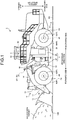
- the wheel loader 1 includes a vehicle body 2, a cab 3 provided with a driver's seat, a traveling device 4 supporting the vehicle body 2, work equipment 10 supported by the vehicle body 2, a transmission device 30, a three-dimensional measurement device 20 that measures a measurement target in front of the vehicle body 2, and a control device 80.
- the vehicle body 2 includes a front vehicle body 2F and a rear vehicle body 2R.
- the front vehicle body 2F and the rear vehicle body 2R are coupled via a joint mechanism 9 so as to be bendable.
- the cab 3 is supported by the vehicle body 2. At least a part of the wheel loader 1 is operated by a driver on the cab 3.
- the traveling device 4 supports the vehicle body 2.
- the traveling device 4 includes wheels 5.
- the wheels 5 are rotated by driving force generated by an engine mounted on the vehicle body 2.
- the wheels 5 are mounted with tires 6.
- the wheels 5 include two front wheels 5F mounted on the front vehicle body 2F and two rear wheels 5R mounted on the rear vehicle body 2R.
- the tires 6 include front tires 6F mounted on the front wheels 5F and rear tires 6R mounted on the rear wheels 5R.
- the traveling device 4 is capable of traveling on the ground RS.
- the direction parallel to the rotation axis FX of the front wheels 5F is appropriately referred to as a vehicle width direction
- the direction orthogonal to the ground contact surfaces of the front tires 6F in contact with the ground RS is appropriately referred to as a vertical direction
- the direction orthogonal to both the vehicle width direction and the vertical direction is appropriately referred to as a front-rear direction.
- a position or a direction close to the center line of the vehicle body 2 in the vehicle width direction is appropriately referred to as an inside or an inward side of the vehicle width direction
- a position or a direction far from the center line of the vehicle body 2 is appropriately referred to as an outside or an outward side of the vehicle width direction.
- one side of the center line of the vehicle body 2 is appropriately referred to as a right side or a rightward side
- the opposite side or the opposite direction of the right side or the rightward side is appropriately referred to as a left side or a leftward side.
- a position or a direction close to the working equipment 10 with respect to the driver's seat of the cab 3 is appropriately referred to as a front side or a forward side
- the opposite side or the opposite direction of the front side or the forward side is appropriately referred to as a rear side or a backward side
- a position or a direction close to the ground contact surfaces of the front tires 6F in the vertical direction is appropriately referred to as a lower side or a downward side
- the opposite side or the opposite direction of the lower side or the downward side is appropriately referred to as an upper side or an upward side.
- the front vehicle body 2F is disposed on the front side of the rear vehicle body 2R.
- the front wheels 5F and the front tires 6F are disposed on the front side of the rear wheels 5R and the rear tires 6R.
- the front wheels 5F and the front tires 6F are disposed on both sides of the vehicle body 2 in the vehicle width direction.
- the rear wheels 5R and the rear tires 6R are disposed on both sides of the vehicle body 2 in the vehicle width direction.
- the front vehicle body 2F bends left and right with respect to the rear vehicle body 2R.
- the traveling device 4 includes a driving device 4A, a braking device 4B, and a steering device 4C.
- the driving device 4A generates driving force for accelerating the wheel loader 1.
- the driving device 4A includes an internal combustion engine, such as a diesel engine.
- the driving force generated by the driving device 4A is transmitted to the wheels 5 via the transmission device 30 to rotate the wheels 5.
- the braking device 4B generates braking force for decelerating or stopping the wheel loader 1.
- the steering device 4C is capable of adjusting the traveling direction of the wheel loader 1.
- the traveling direction of the wheel loader 1 includes the facing direction of the front vehicle body 2F.
- the steering device 4C bends the front vehicle body 2F with a hydraulic cylinder to adjust the traveling direction of the wheel loader 1.
- the traveling device 4 is operated by a driver on the cab 3.
- the working equipment 10 is controlled by a control device 80.
- a traveling operation device 40 that operates the traveling device 4 is disposed on the cab 3.
- the driver operates the traveling operation device 40 to operate the traveling device 4.
- the traveling operation device 40 includes an accelerator pedal, a brake pedal, a steering lever, and a shift lever for switching moving forward and backward.
- the accelerator pedal By operating the accelerator pedal, the traveling speed of the wheel loader 1 is increased.
- the brake pedal the traveling speed of the wheel loader 1 is reduced, or traveling is stopped.
- By operating the steering lever the wheel loader 1 is swung.
- By operating the shift lever moving forward/backward of the wheel loader 1 is switched.
- the transmission device 30 transmits the driving force generated by the driving device 4A to the wheels 5.
- the working equipment 10 includes a boom 11 rotatably coupled to the front vehicle body 2F, a bucket 12 rotatably coupled to the boom 11, a bell crank 15, and a link 16.
- the boom 11 is operated by power generated by a boom cylinder 13.
- the boom cylinder 13 expands and retracts, and the boom 11 is thereby raised or lowered.
- the bucket 12 performs the dumping operation, and the excavated object scooped up by the bucket 12 is thereby discharged from the bucket 12.
- the bucket 12 performs the tilt operation, and the bucket 12 thereby scoops the excavated object.
- the three-dimensional measurement device 20 is mounted on the wheel loader 1.
- the three-dimensional measurement device 20 is supported by a housing 17.
- the three-dimensional measurement device 20 measures a measurement target in front of the front vehicle body 2F.
- the measurement target includes an excavation target of the working equipment 10.
- the measurement target includes a loading target on which an excavated object excavated by the working equipment 10 is loaded.
- the three-dimensional measurement device 20 measures a relative position from the three-dimensional measurement device 20 to each of a plurality of measurement points on the surface of the work target. That is, the three-dimensional measurement device 20 measures the three-dimensional shape of the measurement target.
- the control device 80 to be described later calculates, based on the measured three-dimensional shape of the work target, the distance between the distal end 12B of the working equipment of the wheel loader 1 and the work target.
- the measurement data of the three-dimensional measurement device 20 is three-dimensional data indicating the three-dimensional shape of the work target.
- the three-dimensional data includes point group data regarding the measurement points.
- the measurement data of the three-dimensional measurement device 20 may include image data.
- the three-dimensional measurement device 20 includes a laser radar 21, which is one of laser measurement devices, and a stereo camera 22, which is one of photographic measurement devices.
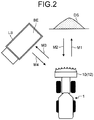
- FIG. 2 is a diagram schematically illustrating an operation of the wheel loader 1 according to the present embodiment.
- the wheel loader 1 works in a plurality of work modes.
- the work modes include an excavation work mode in which the bucket 12 excavates an excavation target, and a loading work mode in which the excavated object scooped by the bucket 12 in the excavation work mode is loaded onto a loading target.
- the excavation target is, for example, natural ground DS on the ground RS.
- the loading target is, for example, a vessel BE (dump body) of a transport vehicle LS capable of traveling on the ground.
- the transport vehicle LS is, for example, a dump truck.
- the wheel loader 1 moves forward toward the natural ground DS to excavate the natural ground DS with the bucket 12, while no excavated object is held in the bucket 12.
- the driver of the wheel loader 1 operates the traveling operation device 40 to move the wheel loader 1 forward to approach the natural ground DS, as indicated by the arrow M1 in FIG. 2 .
- the three-dimensional measurement device 20 mounted on the wheel loader 1 measures the three-dimensional shape of the natural ground DS.
- the control device 80 calculates, based on the measurement data of the three-dimensional measurement device 20, the distance from the wheel loader 1 to the natural ground DS and controls the working equipment 10 so that the bucket 12 excavates the natural ground DS. That is, the control device 80 controls the working equipment 10 so that the distal end 12B and the bottom surface of the bucket 12 are brought into contact with the ground RS, while the wheel loader 1 is moving forward to approach the natural ground DS.
- the wheel loader 1 moves backward to be separated from the natural ground DS, while the excavated object is held in the bucket 12.
- the driver of the wheel loader 1 operates the traveling operation device 40 to move the wheel loader 1 backward to be separated from the natural ground DS, as indicated by the arrow M2 in FIG. 2 .
- the loading work mode is performed.
- the wheel loader 1 moves forward toward the transport vehicle LS to load the excavated object excavated by the bucket 12, while the excavated object is held in the bucket 12.
- the driver of the wheel loader 1 operates the traveling operation device 40 to approach the transport vehicle LS by swinging and moving forward the wheel loader 1, as indicated by the arrow M3 in FIG. 2 .
- the three-dimensional measurement device 20 mounted on the wheel loader 1 measures the three-dimensional shape of the transport vehicle LS.
- the wheel loader 1 moves backward to be separated from the transport vehicle LS, while no excavated object is held in the bucket 12.
- the driver operates the traveling operation device 40 to move the wheel loader 1 backward to be separated from the transport vehicle LS, as indicated by the arrow M4 in FIG. 2 .
- the driver and the control device 80 repeat the above operation until the vessel BE is filled with the excavated objects.
- the three-dimensional measurement device 20 mounted on the wheel loader 1 measures the three-dimensional shape of the natural ground DS.
- the control device 80 determines, based on the measurement data of the three-dimensional measurement device 20, the position of a boundary DP between the ground RS and the natural ground DS.
- the control device 80 calculates, based on the measurement data of the three-dimensional measurement device 20, the distance between the distal end 12B of the bucket 12 and the boundary DP, lowers the boom 11, and controls the angle of the bucket 12 so that the distal end 12B of the bucket 12 approaches the boundary DP, while the wheel loader 1 is moving forward to approach the natural ground DS.
- the wheel loader 1 further moves forward, and the distal end 12B of the bucket 12 is thereby inserted from the boundary DP into the natural ground DS.
- the natural ground DS is thereby excavated by the bucket 12, and the bucket 12 can scoop the excavated object.
- FIG. 4 is a functional block diagram illustrating the control device 80 of the wheel loader 1 according to the present embodiment.
- the control device 80 includes a computer system.
- the control device 80 is connected to the working equipment 10, the three-dimensional measurement device 20, and an angle sensor 50.
- the control device 80 includes a measurement-data acquisition unit 81, a storage unit 82, a target calculation unit 86, and a working-equipment control unit 87.
- the measurement-data acquisition unit 81 acquires measurement data from the three-dimensional measurement device 20.
- the storage unit 82 stores algorithms for processing the measurement data acquired by the measurement-data acquisition unit 81.
- the storage unit 82 stores an algorithm for processing the measurement data regarding the natural ground DS measured by the stereo camera 22 and an algorithm for processing the measurement data regarding the natural ground DS measured by the laser radar 21.
- the algorithms are a procedure, a flowchart, a method, or a program for outputting predetermined data using the measurement data acquired by the measurement-data acquisition unit 81.
- the procedure, the method, or the program may be different, or the number of pieces of or types of output data may be different.
- the target calculation unit 86 calculates, based on the measurement data acquired by the measurement-data acquisition unit 81, the distance from the wheel loader 1 to the work target.
- the target calculation unit 86 may calculate, in addition to the data regarding the distance from the wheel loader 1 to the natural ground DS, the angle data regarding the angle of repose of the natural ground DS, and other parameters regarding the natural ground DS.
- the parameters regarding the natural ground DS include the data regarding the distance from the wheel loader 1 to the natural ground, the angle data regarding the angle of repose of the natural ground DS, the quality of the rock and soil of the natural ground DS, the grain size of the rock and soil forming the natural ground DS, the height of the natural ground DS, the distance to the top of the natural ground DS, the shape of the natural ground DS, and the volume of the natural ground DS.
- the working-equipment control unit 87 controls, based on the data regarding the distance between the wheel loader 1 and the boundary DP calculated by the target calculation unit 86, the working equipment 10 that excavates the natural ground DS. In addition, the working-equipment control unit 87 controls, based on the angle data indicating the angle of repose of the natural ground DS calculated by the target calculation unit 86, the working equipment 10 that excavates the natural ground DS.
- the control of the operation of working equipment 10 includes the control of the operation of at least one of the boom cylinder 13 and the bucket cylinder 14.
- the wheel loader 1 includes a hydraulic pump (not illustrated), a boom control valve (not illustrated) that controls the flow rate and direction of the hydraulic oil supplied from the hydraulic pump to the boom cylinder 13, and a bucket control valve (not illustrated) that controls the flow rate and direction of the hydraulic oil supplied from the hydraulic pump to the bucket cylinder 14.
- the working-equipment control unit 87 outputs a control signal to the boom control valve to control the flow rate and direction of the hydraulic oil supplied to the boom cylinder 13, thereby controlling raising and lowering of the boom 11, and the speed of the raising and lowering.
- the working-equipment control unit 87 further outputs a control signal to the bucket control valve to control the flow rate and direction of the hydraulic oil supplied to the bucket cylinder 14, thereby controlling the dumping operation and the tilt operation of the bucket 12, and the operation speed.
- the wheel loader 1 includes a transmission control unit 88 and a traveling control unit 89.
- the transmission control unit 88 controls, based on the operation of the traveling operation device 40 by the driver of the wheel loader 1, the operation of the transmission device 30, that is, shift change.
- the traveling control unit 89 controls, based on the operation of the traveling operation device 40 by the driver of the wheel loader 1, the operation of the traveling device 4.
- the traveling control unit 89 outputs operation commands including an accelerator command for operating the driving device 4A, a brake command for operating the braking device 4B, and a steering command for operating the steering device 4C.
- FIG. 5 is a flowchart illustrating a control method of the wheel loader 1 according to the present embodiment and illustrates excavation work based on the measurement data of the stereo camera 22 regarding the transport vehicle LS.
- the stereo camera 22 measures a measurement target including at least the natural ground DS.
- the ground RS or an object around the natural ground DS are disposed as the measurement target in addition to the natural ground DS.
- the measurement-data acquisition unit 81 acquires measurement data from the stereo camera 22 (step S10).
- the measurement data of the stereo camera 22 includes the image data regarding the measurement target.
- the image data is constituted by a plurality of pixels.
- the image data regarding the measurement target includes first image data acquired by a first camera 22A and second image data acquired by a second camera 22B.
- the stereo camera 22 performs a stereo process on the image data (the first image data and the second image data) to calculate three-dimensional-shape data.
- the three-dimensional-shape data includes point group data, which is a set of point data calculated for each pixel of the image data of the stereo camera 22.
- the point group data is, for example, data regarding the distance from the stereo camera.
- the target calculation unit 86 determines the ridgeline of the natural ground DS and calculates, based on the three-dimensional-shape data regarding the ridgeline, and outputs the distance from the wheel loader 1 to the natural ground DS or the angle of repose of the natural ground DS.
- the target calculation unit 86 divides the three-dimensional-shape data acquired by the stereo camera 22 into a plurality of areas DA (step S30).
- FIG. 6 is a diagram illustrating an example of image data acquired by the stereo camera 22 according to the present embodiment.
- the target calculation unit 86 divides the image data into a plurality of areas DA.
- the target calculation unit 86 divides the image data in the vertical direction to generate a plurality of areas DA.
- the point group data of each of the areas DA generated by dividing the image data is appropriately referred to as divided point group data.
- the target calculation unit 86 divides the image data in the vertical direction to generate a plurality of areas DA.
- Each of the areas DA is long in the left-right direction.
- Each of the areas DA includes divided point group data indicating the distance from the wheel loader 1 (the stereo camera 22) to the natural ground DS.
- the target calculation unit 86 determines, based on the divided point group data, a ridgeline RD of the natural ground DS in each of the areas DA.
- the ridgeline RD is a line connecting an arbitrary natural ground from a top DT of the natural ground DS to the boundary DP of the ground, and an approximate ridgeline RD can be derived by, for example, extracting several points near the midpoint in each of the areas DA.
- the target calculation unit 86 can determine a diagonal ridgeline RD1 when several points near the midpoint are extracted in each of the areas DA.
- the ridgeline RD may be a front ridgeline RD2 or a side ridgeline RD3.
- extraction is possible by using several points that are not near the midpoint but have the closest distance in the point group data.
- the initial value 1 is set to the counter n (step S40).
- the target calculation unit 86 determines the point data corresponding to the ridgeline RD in each of the first area DA1 to the N-th area DAN.
- the target calculation unit 86 calculates the distance indicated by each of the pixels in one area DA and determines the intermediate value RP of the distances in the area DA (step S50).
- the intermediate value RP may be one or more. If there are a plurality of intermediate values RP, several points near the intermediate values RP are determined.
- the intermediate value RP is the data at the center of the sorted data in the area DA and is also called a median value or a middle value.
- the intermediate value RP is calculated for each of the areas DA.
- the target calculation unit 86 performs the process in step S50 described above on each of the areas DA. That is, the target calculation unit 86 determines whether the process for calculating the intermediate value RP has been completed for all the areas DA (step S60). When it is determined that the process for calculating the intermediate value RP has not been completed for all the areas DA (step S60: No), the counter n is incremented (step S70), and the process returns to step S50.
- the target calculation unit 86 integrates the areas DA and performs linear fitting on the intermediate values RP calculated for the areas DA.
- the target calculation unit 86 determines an approximate ridgeline RD by a straight line fitting process.
- FIG. 7 illustrates an example of performing the linear fitting process on a plurality of intermediate values RP according to the present embodiment.
- the target calculation unit 86 performs a linear fitting process on a plurality of intermediate values RP and calculates an approximate ridgeline RE based on the intermediate values RP (step S80).
- the ridgeline RE indicates the shape of the slope of the natural ground DS.
- the ridgeline RE indicates the angle of repose ⁇ of the slope of the natural ground DS with respect to the ground RS.
- the target calculation unit 86 calculates the angle of repose ⁇ of the natural ground DS based on the ridgeline RE (step S85).
- the position of the slope of the natural ground DS is defined in the vehicle body coordinate system of the wheel loader 1.
- the installation position of the stereo camera 22 in the vehicle body coordinate system is known data derived from the design data of the wheel loader 1.
- the target calculation unit 86 calculates the position of the ground RS based on the ground contact surfaces of the tires 6 (step S90).
- the positions of the contact surfaces of the tires 6 in the vehicle body coordinate system are known data derived from the design data of the wheel loader 1.
- the position of the ground RS in the vehicle body coordinate system is determined by the ground contact surfaces of at least three tires 6 of the four tires 6.
- the position of the ground RS may be calculated based on the image data of the stereo camera 22.
- the position of the ground RS may be determined based on the contact surfaces of the tires 6, the point group data regarding the ground RS measured by the stereo camera 22 may be removed.
- the target calculation unit 86 calculates the position of the boundary DP between the ridgeline RD of the natural ground DS and the ground RS (step S100).
- the target calculation unit 86 calculates and outputs the distance from the wheel loader 1 to the natural ground DS and the angle of repose ⁇ of the natural ground DS (step S110).
- the distance from the wheel loader 1 to the natural ground DS may be the distance from the distal end 12B of the bucket 12 to the boundary DP.
- the distance from the distal end 12B of the working equipment 10 to the boundary DP is calculated using, in addition to the distance from the stereo camera 22 to the boundary DP, the installation position of the stereo camera 22, the installation position of the working equipment 10, and the size and angle of the working equipment 10 in the vehicle body coordinate system.
- the working-equipment control unit 87 lowers the boom 11 and controls the angle of the bucket 12 so that the distal end 12B of the bucket 12 approaches the boundary DP, while the wheel loader 1 is moving forward to approach the natural ground DS.
- the wheel loader 1 further moves forward, and the distal end 12B of the bucket 12 is thereby inserted from the boundary DP into the natural ground DS.
- the natural ground DS is thereby excavated by the bucket 12, and the bucket 12 can scoop the excavated object.
- the working equipment 10 is controlled based on the three-dimensional-shape data regarding the natural ground DS, and the working equipment 10 of the wheel loader 1 can thereby move to an excavation start point of the natural ground DS defined by the boundary DP.
- the wheel loader 1 can properly excavate the natural ground DS.
- the three-dimensional-shape data regarding the natural ground DS includes the angle of repose of the natural ground DS. Depending on the angle of repose ⁇ , the traction force after plunging in the natural ground DS, the rising speed of the working equipment 10, and the like can be controlled.
- the image data has been divided to determine the ridgeline, but the same process without dividing may be performed to determine the ridgeline.
- FIG. 8 is a diagram schematically illustrating a control method of the wheel loader 1 according to the present embodiment and is a diagram illustrating the operation of the laser radar 21.
- the laser radar 21 irradiates each of a plurality of irradiation points PJ on the surface of a measurement target with laser light to measure the distance to each of the irradiation points PJ.
- the target calculation unit 86 classifies, based on the distance from the wheel loader 1 (laser radar 21) to each of the irradiation points PJ, the irradiation points PJ into a plurality of groups and determines, based on at least one of the inclination K (angle of inclination) of each of the groups with respect to the ground RS and the height of gravitational center H of each of the groups, the measurement target.
- the measurement target in the excavation work mode includes at least one of the ground RS, the natural ground DS, and an object around the natural ground DS.
- the target calculation unit 86 determines, based on at least one of the angle of inclination K of each of the groups and the height of gravitational center H of each of the groups, whether the measurement target is the ground RS or the natural ground DS.
- the target calculation unit 86 groups a plurality of irradiation points PJ based on the distance to each of the irradiation points PJ.
- Grouping means, for example, grouping a plurality of irradiation points PJ each having the difference in distance to its adjacent irradiation point PJ equal to or less than a predetermined threshold as one group.
- the difference in the distance between an irradiation point PJa defined by irradiating the surface of the measurement target and an irradiation point PJb defined by irradiating a part of the working equipment 10 is large.
- irradiation points PJa defined on the surface of the measurement target are grouped as one group
- irradiation points PJb defined on the surface of the working equipment 10 are grouped as another group.
- the target calculation unit 86 removes the group of the irradiation points PJb indicating the working equipment 10, divides the group of the irradiation points PJa indicating the measurement target into groups, and classifies the irradiation points PJ into a first group and a second group.
- the division point PJK is an irradiation point PJ that is an inflection point on a virtual line connecting a plurality of irradiation points PJ constituting one group.
- the irradiation points PJ can be divided into two groups each arranged in a straight line as illustrated in FIG. 9(B) .
- the target calculation unit 86 can divide and classify the irradiation points PJ into the first group and the second group.
- the grouping method is not limited to the method in the present embodiment, and other algorithms may be used for grouping.
- the target calculation unit 86 performs a fitting process on the irradiation points PJ of each of the first group and the second group. After performing the fitting process, the target calculation unit 86 calculates the inclination K of each of the groups with respect to the ground RS and the height of gravitational center H of each of the groups. In the example illustrated in FIG. 9 , the target calculation unit 86 calculates the inclination K1 and the height of gravitational center H1 of the first group, and the inclination K2 and the height of gravitational center H2 of the second group.
- the target calculation unit 86 determines, based on at least one of the angle of inclination K of each of the groups and the height of gravitational center H of each of the groups, whether the measurement target is the ground RS or the natural ground DS.
- the group can be determined to be the ground RS. Since the surface of the natural ground DS is inclined with respect to the ground RS, when the angle of inclination K of a group is equal to or larger than the angle threshold, the group can be determined to be the natural ground DS.
- the target calculation unit 86 may determine that the group is the natural ground DS. When the height of gravitational center H of a group is less than the height threshold, the target calculation unit 86 may determine that the group is the ground RS.
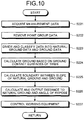
- FIG. 10 is a flowchart illustrating a control method of the wheel loader 1 according to the present embodiment and illustrates a method for a process based on the measurement data of the laser radar 21 regarding the natural ground DS.
- the laser light emitted from the laser radar 21 is applied not only to the natural ground DS but also to the ground RS or an object around the natural ground DS.
- the target calculation unit 86 removes, based on the distance to each of the irradiation points PJ, the point group data regarding the working equipment 10 and the point group data regarding the outliers (step S222).
- the target calculation unit 86 divides the point group data regarding the irradiation points PJ indicating the measurement target into groups. In addition, as described with reference to FIG. 9(B) , the target calculation unit 86 determines, for each divided group, the ground RS and the natural ground DS based on at least one of the angle of inclination K of the group with respect to the ground RS and the height of gravitational center H of the group with respect to the ground RS.
- the target calculation unit 86 divides and classifies the point group data regarding the irradiation points PJ into a natural-ground group and a ground group (step S223).
- the target calculation unit 86 calculates the position of the ground RS based on the ground contact surfaces of the tires 6 (step S224).
- the target calculation unit 86 may calculate the position of the ground RS based on the point group data regarding the irradiation points PJ of the ground group classified in step S223.
- the ridgeline of the natural ground DS can be calculated. After the position of the ridgeline of the natural ground DS and the position of the ground RS are calculated, the target calculation unit 86 calculates the position of the boundary DP between the ridgeline of the natural ground DS and the ground RS (step S225).
- the working equipment 10 is controlled based on the three-dimensional data regarding the natural ground DS, and the working equipment 10 can thereby move to the boundary DP which is the excavation start point.
- the three-dimensional-shape data regarding the natural ground DS includes the angle of repose of the natural ground DS. Depending on the angle of repose ⁇ , the traction force after the working equipment 10 plunges in the natural ground DS, the rising speed of the working equipment 10, and the like can be controlled.
- the distance to the boundary DP of the natural ground DS is calculated using the stereo camera 22 and the laser radar 21, the distance can be accurately calculated from a position where the wheel loader 1 is away from the natural ground DS while the wheel loader 1 is approaching the natural ground DS.
- the working equipment 10 can be controlled to a desired position before the wheel loader 1 reaches the natural ground DS, the working equipment 10 can be controlled with enough time.
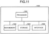
- the computer system 1000 including the control device 80 is capable of acquiring measurement data of the three-dimensional measurement device 20 that is mounted on the excavating machine 1 including the working equipment 10 and measures a three-dimensional shape of an excavation target to be excavated by the working equipment 10, determining a ridgeline of the excavation target, and calculating and outputting, based on the measurement data regarding the ridgeline, the distance from the excavating machine to the excavation target or the angle of repose of the excavation target.
- the ridgeline of the natural ground DS has been determined with the stereo camera 22 that uses point group data or the laser radar 21 that performs groupings, but determination of the ridgeline is not limited thereto.
- the ridgeline of the natural ground DS may be determined by, for example, an image recognition technology, a method using artificial intelligence based on the arrangement of the point group data, or other algorithms.
- the ground data may be determined and removed from the point group data based on some algorithm, and the remaining data may be determined to be the ground data.
- the target calculation unit 86 has calculated the distance from the wheel loader 1 to the natural ground DS and the angle of repose of the natural ground DS as the parameters of the natural ground DS, but is not limited thereto, and may calculate and output other parameters of the natural ground DS.
- the working-equipment control unit 87 has been controlled the working equipment 10 based on the data regarding the distance from the wheel loader 1 to the boundary DP.
- the target calculation unit 86 is capable of calculating the angle data indicating the angle of repose ⁇ of the natural ground DS based on the measurement data of the three-dimensional measurement device 20.
- the working-equipment control unit 87 may control the working equipment 10 based on the angle data.
- the measurement device mounted on the wheel loader 1 has been the three-dimensional measurement device 20, and the measurement data acquired by the measurement-data acquisition unit 81 has been three-dimensional data indicating the three-dimensional shape of the work target, but they are not limited thereto.
- the measurement device in addition to the three-dimensional measurement device 20 that measures the work target, the camera, which is a photographic measurement device for photographing the work target, and a position measurement device for measuring the position of the work target may be mounted on the wheel loader 1.
- the measurement device may include an excavated-object determination sensor.
- the measurement data acquired by the measurement-data acquisition unit 81 includes, in addition to the three-dimensional data of the work target, at least one of the image data of the work target captured by the camera, the position data of the work target measured by the position measurement device, and the detection data of the excavated-object determination sensor.
- the target calculation unit 86 may determine the position of the boundary DP between the excavation target and the ground and calculate the distance between the wheel loader 1 and the boundary DP by an image recognition technology using the image data obtained by imaging the excavation target.
- an image recognition technology a known image recognition technology can be used to determine the position of the boundary DP between the excavation target and the ground.
- the distance from the distal end 12B of the bucket 12 has been exemplified as the distance from the wheel loader 1 to the work target, but the distance from the wheel loader 1 to the work target is not limited thereto and may be the distance from another part of the bucket 12 or from any part of the wheel loader 1.
- the working-equipment control unit 87 may consider the traveling speed of the wheel loader 1 in addition to the distance to the natural ground DS.
- the transmission device 30 and the traveling device 4 have been operated by the driver operating the traveling operation device 40, but the transmission control unit 88 and the traveling control unit 89 may automatically control, based on the distance to the natural ground DS and the angle of repose ⁇ , the transmission device 30 and the traveling device 4.
- the distance to the natural ground DS and the angle of repose ⁇ may be displayed on a display device.
- the display device may be provided on the cab 3.
- data indicating the distance to the natural ground DS and the angle of repose ⁇ may be transmitted to a server outside the wheel loader 1.
- both the laser radar 21 and the stereo camera 22 have been provided in the wheel loader 1 as the three-dimensional measurement device 20.
- One of the laser radar 21 and the stereo camera 22 may be provided in the wheel loader 1.
- the three-dimensional measurement device 20 is only required to measure the three-dimensional shape of the work target and the relative position with the work target and is not limited to the laser radar 21 and the stereo camera 22.
- the distance to the natural ground DS and the angle of repose ⁇ have been calculated, but either one of the distance to the natural ground DS and the angle of repose ⁇ may be calculated, and the working equipment 10 may be controlled based on the calculation result.
- the work target is not limited to the excavation target and may include, for example, an embankment target, a land leveling target, and an earth removal target.
- the work site where the wheel loader 1 works may be a mining site, a construction site, or a building site.
- the wheel loader 1 may be used for snow removal work, work in the agriculture and livestock industry, or work in the forestry industry.
- the bucket 12 may have a plurality of blades or may have a straight blade edge.
- the working member coupled to the distal end of the boom 11 may not be the bucket 12 and may be a snow plow or a snow bucket used for snow removal work, a bale glove or a fork used for work in the agriculture and livestock industry, or a fork or a bucket used for work in the forestry industry.
- the work machine is not limited to the wheel loader and also includes an excavating machine including work equipment, such as an excavator or a bulldozer.
- An excavating machine including work equipment, such as an excavator or a bulldozer.
Landscapes
- Engineering & Computer Science (AREA)
- General Engineering & Computer Science (AREA)
- Structural Engineering (AREA)
- Mining & Mineral Resources (AREA)
- Civil Engineering (AREA)
- Physics & Mathematics (AREA)
- General Physics & Mathematics (AREA)
- Mechanical Engineering (AREA)
- Radar, Positioning & Navigation (AREA)
- Computer Networks & Wireless Communication (AREA)
- Electromagnetism (AREA)
- Remote Sensing (AREA)
- Theoretical Computer Science (AREA)
- Computer Vision & Pattern Recognition (AREA)
- Operation Control Of Excavators (AREA)
- Length Measuring Devices By Optical Means (AREA)
- Optical Radar Systems And Details Thereof (AREA)
Abstract
Description
- The present invention relates to a work machine control device, an excavating machine control device, and a work machine control method.
- Work machines are used at work sites.
Patent Literature 1 discloses an example of an automatic excavator equipped with a measurement device for measuring distances to an excavation target and a loading target. - Patent Literature 1:
JP H10-088625 A - In order to automate work of a work machine, it is desired to acquire a parameter regarding a work target.
- An aspect of the present invention is to acquire a parameter regarding a work target.
- According to an aspect of the present invention, a work machine control device comprises: a measurement-data acquisition unit configured to acquire measurement data of a three-dimensional measurement device configured to measure a three-dimensional shape including a ridgeline of a work target on which work equipment performs work, the three-dimensional measurement device being mounted on a work machine including the working equipment; and a target calculation unit configured to calculate and output, based on the measurement data regarding the ridgeline of the work target, a distance from the work machine to the work target or an angle of repose of the work target.
- According to an aspect of the present invention, it is possible to acquire a parameter regarding a work target.
-
-
FIG. 1 is a side view illustrating an excavating machine according to a first embodiment. -
FIG. 2 is a front view illustrating the excavating machine according to the first embodiment. -
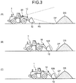
FIG. 3 is a diagram schematically illustrating an operation of the excavating machine according to the first embodiment. -
FIG. 4 is a diagram schematically illustrating an excavation work mode of the excavating machine according to the first embodiment. -
FIG. 5 is a functional block diagram illustrating an excavating machine control device according to the first embodiment. -
FIG. 6 is a flowchart illustrating an excavating machine control method the according to the first embodiment. -
FIG. 7 is a diagram schematically illustrating the excavating machine control method according to the first embodiment. -
FIG. 8 is a diagram schematically illustrating the excavating machine control method according to the first embodiment. -
FIG. 9 is a diagram schematically illustrating an excavating machine control method according to a second embodiment. -
FIG. 10 is a diagram schematically illustrating the excavating machine control method according to the second embodiment. -
FIG. 11 is a flowchart illustrating the excavating machine control method according to the second embodiment. Description of Embodiments - Hereinafter, embodiments of the present invention are described with reference to the drawings, but the present invention is not limited thereto. The constituent elements of the embodiment described below can be appropriately combined. In addition, some constituent elements cannot be used.
-
FIG. 1 is a side view illustrating an example of anexcavating machine 1 according to the present embodiment. Theexcavating machine 1 performs predetermined work on a work target at a work site. In the present embodiment, theexcavating machine 1 is assumed to be awheel loader 1, which is one of articulate excavating machines. The predetermined work includes excavation work and loading work. The work target includes an excavation target and a loading target. Thewheel loader 1 performs excavation work for excavating an excavation target and loading work for loading an excavated object excavated by the excavation work on a loading target. The loading work is a concept including discharging work for discharging the excavated object to a discharging target. The excavation target is, for example, at least one of natural ground, a rock pile, coal, and a wall surface. The natural ground is a mountain formed of earth and sand, and the rock pile is a mountain formed of rock or stone. The excavation target may be a mountain formed of at least one of crushed stone, ore, and coal. The loading target is, for example, at least one of a transport vehicle, a predetermined area of a work site, a hopper, a belt conveyor, and a crusher. - As illustrated in
FIG. 1 , thewheel loader 1 includes avehicle body 2, acab 3 provided with a driver's seat, a traveling device 4 supporting thevehicle body 2,work equipment 10 supported by thevehicle body 2, atransmission device 30, a three-dimensional measurement device 20 that measures a measurement target in front of thevehicle body 2, and acontrol device 80. - The
vehicle body 2 includes afront vehicle body 2F and arear vehicle body 2R. Thefront vehicle body 2F and therear vehicle body 2R are coupled via a joint mechanism 9 so as to be bendable. - The
cab 3 is supported by thevehicle body 2. At least a part of thewheel loader 1 is operated by a driver on thecab 3. - The traveling device 4 supports the
vehicle body 2. The traveling device 4 includeswheels 5. Thewheels 5 are rotated by driving force generated by an engine mounted on thevehicle body 2. Thewheels 5 are mounted withtires 6. Thewheels 5 include twofront wheels 5F mounted on thefront vehicle body 2F and tworear wheels 5R mounted on therear vehicle body 2R. Thetires 6 includefront tires 6F mounted on thefront wheels 5F andrear tires 6R mounted on therear wheels 5R. The traveling device 4 is capable of traveling on the ground RS. - In the following description, the direction parallel to the rotation axis FX of the
front wheels 5F is appropriately referred to as a vehicle width direction, the direction orthogonal to the ground contact surfaces of thefront tires 6F in contact with the ground RS is appropriately referred to as a vertical direction, and the direction orthogonal to both the vehicle width direction and the vertical direction is appropriately referred to as a front-rear direction. When thevehicle body 2 of thewheel loader 1 travels straight, the rotation axis FX and the rotation axis RX are parallel to each other. - In addition, in the following description, a position or a direction close to the center line of the
vehicle body 2 in the vehicle width direction is appropriately referred to as an inside or an inward side of the vehicle width direction, and a position or a direction far from the center line of thevehicle body 2 is appropriately referred to as an outside or an outward side of the vehicle width direction. In addition, in the vehicle width direction, one side of the center line of thevehicle body 2 is appropriately referred to as a right side or a rightward side, and the opposite side or the opposite direction of the right side or the rightward side is appropriately referred to as a left side or a leftward side. In addition, in the front-rear direction, a position or a direction close to theworking equipment 10 with respect to the driver's seat of thecab 3 is appropriately referred to as a front side or a forward side, and the opposite side or the opposite direction of the front side or the forward side is appropriately referred to as a rear side or a backward side. In addition, a position or a direction close to the ground contact surfaces of thefront tires 6F in the vertical direction is appropriately referred to as a lower side or a downward side, and the opposite side or the opposite direction of the lower side or the downward side is appropriately referred to as an upper side or an upward side. - The
front vehicle body 2F is disposed on the front side of therear vehicle body 2R. Thefront wheels 5F and thefront tires 6F are disposed on the front side of therear wheels 5R and therear tires 6R. Thefront wheels 5F and thefront tires 6F are disposed on both sides of thevehicle body 2 in the vehicle width direction. Therear wheels 5R and therear tires 6R are disposed on both sides of thevehicle body 2 in the vehicle width direction. Thefront vehicle body 2F bends left and right with respect to therear vehicle body 2R. - The traveling device 4 includes a driving device 4A, a
braking device 4B, and asteering device 4C. The driving device 4A generates driving force for accelerating thewheel loader 1. The driving device 4A includes an internal combustion engine, such as a diesel engine. The driving force generated by the driving device 4A is transmitted to thewheels 5 via thetransmission device 30 to rotate thewheels 5. - The
braking device 4B generates braking force for decelerating or stopping thewheel loader 1. - The
steering device 4C is capable of adjusting the traveling direction of thewheel loader 1. The traveling direction of thewheel loader 1 includes the facing direction of thefront vehicle body 2F. Thesteering device 4C bends thefront vehicle body 2F with a hydraulic cylinder to adjust the traveling direction of thewheel loader 1. - In the present embodiment, the traveling device 4 is operated by a driver on the
cab 3. The workingequipment 10 is controlled by acontrol device 80. A travelingoperation device 40 that operates the traveling device 4 is disposed on thecab 3. The driver operates the travelingoperation device 40 to operate the traveling device 4. The travelingoperation device 40 includes an accelerator pedal, a brake pedal, a steering lever, and a shift lever for switching moving forward and backward. By operating the accelerator pedal, the traveling speed of thewheel loader 1 is increased. By operating the brake pedal, the traveling speed of thewheel loader 1 is reduced, or traveling is stopped. By operating the steering lever, thewheel loader 1 is swung. By operating the shift lever, moving forward/backward of thewheel loader 1 is switched. - The
transmission device 30 transmits the driving force generated by the driving device 4A to thewheels 5. - The working
equipment 10 includes aboom 11 rotatably coupled to thefront vehicle body 2F, abucket 12 rotatably coupled to theboom 11, abell crank 15, and alink 16. - The
boom 11 is operated by power generated by aboom cylinder 13. Theboom cylinder 13 expands and retracts, and theboom 11 is thereby raised or lowered. - The
bucket 12 is a working member including adistal end 12B with a cutting edge. Thebucket 12 is disposed on the front side of thefront wheels 5F. Thebucket 12 is coupled to the distal end of theboom 11. Thebucket 12 is operated by power generated by abucket cylinder 14. Thebucket cylinder 14 expands and retracts, and thebucket 12 thereby performs a dumping operation or a tilt operation. - The
bucket 12 performs the dumping operation, and the excavated object scooped up by thebucket 12 is thereby discharged from thebucket 12. Thebucket 12 performs the tilt operation, and thebucket 12 thereby scoops the excavated object. - The three-
dimensional measurement device 20 is mounted on thewheel loader 1. The three-dimensional measurement device 20 is supported by a housing 17. The three-dimensional measurement device 20 measures a measurement target in front of thefront vehicle body 2F. The measurement target includes an excavation target of the workingequipment 10. In addition, the measurement target includes a loading target on which an excavated object excavated by the workingequipment 10 is loaded. The three-dimensional measurement device 20 measures a relative position from the three-dimensional measurement device 20 to each of a plurality of measurement points on the surface of the work target. That is, the three-dimensional measurement device 20 measures the three-dimensional shape of the measurement target. In addition, thecontrol device 80 to be described later calculates, based on the measured three-dimensional shape of the work target, the distance between thedistal end 12B of the working equipment of thewheel loader 1 and the work target. - The measurement data of the three-
dimensional measurement device 20 is three-dimensional data indicating the three-dimensional shape of the work target. The three-dimensional data includes point group data regarding the measurement points. The measurement data of the three-dimensional measurement device 20 may include image data. - The three-
dimensional measurement device 20 includes alaser radar 21, which is one of laser measurement devices, and astereo camera 22, which is one of photographic measurement devices. -
FIG. 2 is a diagram schematically illustrating an operation of thewheel loader 1 according to the present embodiment. Thewheel loader 1 works in a plurality of work modes. The work modes include an excavation work mode in which thebucket 12 excavates an excavation target, and a loading work mode in which the excavated object scooped by thebucket 12 in the excavation work mode is loaded onto a loading target. The excavation target is, for example, natural ground DS on the ground RS. The loading target is, for example, a vessel BE (dump body) of a transport vehicle LS capable of traveling on the ground. The transport vehicle LS is, for example, a dump truck. - In the excavation work mode, the
wheel loader 1 moves forward toward the natural ground DS to excavate the natural ground DS with thebucket 12, while no excavated object is held in thebucket 12. The driver of thewheel loader 1 operates the travelingoperation device 40 to move thewheel loader 1 forward to approach the natural ground DS, as indicated by the arrow M1 inFIG. 2 . The three-dimensional measurement device 20 mounted on thewheel loader 1 measures the three-dimensional shape of the natural ground DS. Thecontrol device 80 calculates, based on the measurement data of the three-dimensional measurement device 20, the distance from thewheel loader 1 to the natural ground DS and controls the workingequipment 10 so that thebucket 12 excavates the natural ground DS. That is, thecontrol device 80 controls the workingequipment 10 so that thedistal end 12B and the bottom surface of thebucket 12 are brought into contact with the ground RS, while thewheel loader 1 is moving forward to approach the natural ground DS. - After the
bucket 12 plunges into the natural ground DS, excavates the natural ground DS, and scoops the excavated object, thewheel loader 1 moves backward to be separated from the natural ground DS, while the excavated object is held in thebucket 12. The driver of thewheel loader 1 operates the travelingoperation device 40 to move thewheel loader 1 backward to be separated from the natural ground DS, as indicated by the arrow M2 inFIG. 2 . - Next, the loading work mode is performed. In the loading work mode, the
wheel loader 1 moves forward toward the transport vehicle LS to load the excavated object excavated by thebucket 12, while the excavated object is held in thebucket 12. The driver of thewheel loader 1 operates the travelingoperation device 40 to approach the transport vehicle LS by swinging and moving forward thewheel loader 1, as indicated by the arrow M3 inFIG. 2 .
The three-dimensional measurement device 20 mounted on thewheel loader 1 measures the three-dimensional shape of the transport vehicle LS. Thecontrol device 80 calculates, based on the measurement data of the three-dimensional measurement device 20, the distance from thewheel loader 1 to the transport vehicle LS and controls the workingequipment 10 so that the excavated object held in thebucket 12 is loaded onto the vessel BE of the transport vehicle LS. That is, thecontrol device 80 controls the workingequipment 10 so that theboom 11 is raised, while thewheel loader 1 is moving forward to approach the transport vehicle LS. After theboom 11 is raised to position thebucket 12 above the vessel BE, thecontrol device 80 controls the workingequipment 10 so that thebucket 12 performs the tilt operation. The excavated object is thereby discharged from thebucket 12 and loaded on the vessel BE. - After the excavated object is discharged from the
bucket 12 and loaded on the vessel BE, thewheel loader 1 moves backward to be separated from the transport vehicle LS, while no excavated object is held in thebucket 12. The driver operates the travelingoperation device 40 to move thewheel loader 1 backward to be separated from the transport vehicle LS, as indicated by the arrow M4 inFIG. 2 . - The driver and the
control device 80 repeat the above operation until the vessel BE is filled with the excavated objects. -
FIG. 3 is a diagram schematically illustrating the excavation work mode of thewheel loader 1 according to the present embodiment. The driver of thewheel loader 1 operates the travelingoperation device 40 to move thewheel loader 1 forward to approach the natural ground DS. - As illustrated in
FIG. 3(A) , the three-dimensional measurement device 20 mounted on thewheel loader 1 measures the three-dimensional shape of the natural ground DS. Thecontrol device 80 determines, based on the measurement data of the three-dimensional measurement device 20, the position of a boundary DP between the ground RS and the natural ground DS. - As illustrated in
FIG. 3(B) , thecontrol device 80 calculates, based on the measurement data of the three-dimensional measurement device 20, the distance between thedistal end 12B of thebucket 12 and the boundary DP, lowers theboom 11, and controls the angle of thebucket 12 so that thedistal end 12B of thebucket 12 approaches the boundary DP, while thewheel loader 1 is moving forward to approach the natural ground DS. - As illustrated in
FIG. 3(C) , thewheel loader 1 further moves forward, and thedistal end 12B of thebucket 12 is thereby inserted from the boundary DP into the natural ground DS. The natural ground DS is thereby excavated by thebucket 12, and thebucket 12 can scoop the excavated object. -
FIG. 4 is a functional block diagram illustrating thecontrol device 80 of thewheel loader 1 according to the present embodiment. Thecontrol device 80 includes a computer system. - The
control device 80 is connected to the workingequipment 10, the three-dimensional measurement device 20, and anangle sensor 50. - The
control device 80 includes a measurement-data acquisition unit 81, astorage unit 82, atarget calculation unit 86, and a working-equipment control unit 87. - The measurement-data acquisition unit 81 acquires measurement data from the three-
dimensional measurement device 20. - The
storage unit 82 stores algorithms for processing the measurement data acquired by the measurement-data acquisition unit 81. Thestorage unit 82 stores an algorithm for processing the measurement data regarding the natural ground DS measured by thestereo camera 22 and an algorithm for processing the measurement data regarding the natural ground DS measured by thelaser radar 21. The algorithms are a procedure, a flowchart, a method, or a program for outputting predetermined data using the measurement data acquired by the measurement-data acquisition unit 81. Depending on the algorithms, the procedure, the method, or the program may be different, or the number of pieces of or types of output data may be different. - The
target calculation unit 86 calculates, based on the measurement data acquired by the measurement-data acquisition unit 81, the distance from thewheel loader 1 to the work target. Thetarget calculation unit 86 may calculate, in addition to the data regarding the distance from thewheel loader 1 to the natural ground DS, the angle data regarding the angle of repose of the natural ground DS, and other parameters regarding the natural ground DS. The parameters regarding the natural ground DS include the data regarding the distance from thewheel loader 1 to the natural ground, the angle data regarding the angle of repose of the natural ground DS, the quality of the rock and soil of the natural ground DS, the grain size of the rock and soil forming the natural ground DS, the height of the natural ground DS, the distance to the top of the natural ground DS, the shape of the natural ground DS, and the volume of the natural ground DS. - The working-
equipment control unit 87 controls, based on the data regarding the distance between thewheel loader 1 and the boundary DP calculated by thetarget calculation unit 86, the workingequipment 10 that excavates the natural ground DS. In addition, the working-equipment control unit 87 controls, based on the angle data indicating the angle of repose of the natural ground DS calculated by thetarget calculation unit 86, the workingequipment 10 that excavates the natural ground DS. - The control of the operation of working
equipment 10 includes the control of the operation of at least one of theboom cylinder 13 and thebucket cylinder 14. Thewheel loader 1 includes a hydraulic pump (not illustrated), a boom control valve (not illustrated) that controls the flow rate and direction of the hydraulic oil supplied from the hydraulic pump to theboom cylinder 13, and a bucket control valve (not illustrated) that controls the flow rate and direction of the hydraulic oil supplied from the hydraulic pump to thebucket cylinder 14. The working-equipment control unit 87 outputs a control signal to the boom control valve to control the flow rate and direction of the hydraulic oil supplied to theboom cylinder 13, thereby controlling raising and lowering of theboom 11, and the speed of the raising and lowering. The working-equipment control unit 87 further outputs a control signal to the bucket control valve to control the flow rate and direction of the hydraulic oil supplied to thebucket cylinder 14, thereby controlling the dumping operation and the tilt operation of thebucket 12, and the operation speed. - In the present embodiment, the
wheel loader 1 includes atransmission control unit 88 and a travelingcontrol unit 89. - The
transmission control unit 88 controls, based on the operation of the travelingoperation device 40 by the driver of thewheel loader 1, the operation of thetransmission device 30, that is, shift change. - The traveling
control unit 89 controls, based on the operation of the travelingoperation device 40 by the driver of thewheel loader 1, the operation of the traveling device 4. The travelingcontrol unit 89 outputs operation commands including an accelerator command for operating the driving device 4A, a brake command for operating thebraking device 4B, and a steering command for operating thesteering device 4C. -
FIG. 5 is a flowchart illustrating a control method of thewheel loader 1 according to the present embodiment and illustrates excavation work based on the measurement data of thestereo camera 22 regarding the transport vehicle LS. - In the excavation work mode in which the
wheel loader 1 moves forward toward the natural ground DS to excavate the natural ground DS with the workingequipment 10, thestereo camera 22 measures a measurement target including at least the natural ground DS. In the imaging range of the stereo camera 22 (the field of view of the optical system of the stereo camera 22), the ground RS or an object around the natural ground DS are disposed as the measurement target in addition to the natural ground DS. The measurement-data acquisition unit 81 acquires measurement data from the stereo camera 22 (step S10). - The measurement data of the
stereo camera 22 includes the image data regarding the measurement target. The image data is constituted by a plurality of pixels. The image data regarding the measurement target includes first image data acquired by a first camera 22A and second image data acquired by a second camera 22B. Thestereo camera 22 performs a stereo process on the image data (the first image data and the second image data) to calculate three-dimensional-shape data. - The measurement-data acquisition unit 81 acquires, from the
stereo camera 22, the three-dimensional-shape data that is the measurement data of the stereo camera 22 (step S10) . - The three-dimensional-shape data includes point group data, which is a set of point data calculated for each pixel of the image data of the
stereo camera 22. The point group data is, for example, data regarding the distance from the stereo camera. - In the present embodiment, the
target calculation unit 86 determines the ridgeline of the natural ground DS and calculates, based on the three-dimensional-shape data regarding the ridgeline, and outputs the distance from thewheel loader 1 to the natural ground DS or the angle of repose of the natural ground DS. - Since the
stereo camera 22 can acquire a wide range of point group data and measure the topography of a wide area of the natural ground DS, it is difficult to determine which point group data is the data regarding the ridgeline, and the cross section of the natural ground as illustrated inFIG. 7 to be described later cannot be determined. For this reason, in order to determine the ridgeline, thetarget calculation unit 86 divides the three-dimensional-shape data acquired by thestereo camera 22 into a plurality of areas DA (step S30). -
FIG. 6 is a diagram illustrating an example of image data acquired by thestereo camera 22 according to the present embodiment. - The
target calculation unit 86 divides the image data into a plurality of areas DA. In the present embodiment, thetarget calculation unit 86 divides the image data in the vertical direction to generate a plurality of areas DA. In the following description, the point group data of each of the areas DA generated by dividing the image data is appropriately referred to as divided point group data. - The
target calculation unit 86 divides the image data in the vertical direction to generate a plurality of areas DA. Each of the areas DA is long in the left-right direction. Each of the areas DA includes divided point group data indicating the distance from the wheel loader 1 (the stereo camera 22) to the natural ground DS. - Then, the
target calculation unit 86 determines, based on the divided point group data, a ridgeline RD of the natural ground DS in each of the areas DA. The ridgeline RD is a line connecting an arbitrary natural ground from a top DT of the natural ground DS to the boundary DP of the ground, and an approximate ridgeline RD can be derived by, for example, extracting several points near the midpoint in each of the areas DA. - As illustrated in
FIG. 6 , in the present embodiment, thetarget calculation unit 86 can determine a diagonal ridgeline RD1 when several points near the midpoint are extracted in each of the areas DA. The ridgeline RD may be a front ridgeline RD2 or a side ridgeline RD3. In addition, in order to determine the front ridgeline RD2, extraction is possible by using several points that are not near the midpoint but have the closest distance in the point group data. - The
initial value 1 is set to the counter n (step S40). Thetarget calculation unit 86 determines the point data corresponding to the ridgeline RD in each of the first area DA1 to the N-th area DAN. - The
target calculation unit 86 calculates the distance indicated by each of the pixels in one area DA and determines the intermediate value RP of the distances in the area DA (step S50). The intermediate value RP may be one or more. If there are a plurality of intermediate values RP, several points near the intermediate values RP are determined. The intermediate value RP is the data at the center of the sorted data in the area DA and is also called a median value or a middle value. - As described above, the intermediate value RP is calculated for each of the areas DA. The
target calculation unit 86 performs the process in step S50 described above on each of the areas DA. That is, thetarget calculation unit 86 determines whether the process for calculating the intermediate value RP has been completed for all the areas DA (step S60). When it is determined that the process for calculating the intermediate value RP has not been completed for all the areas DA (step S60: No), the counter n is incremented (step S70), and the process returns to step S50. - When it is determined that the process for calculating the intermediate value RP has been completed for all the areas DA (step S60: Yes), the
target calculation unit 86 integrates the areas DA and performs linear fitting on the intermediate values RP calculated for the areas DA. Thetarget calculation unit 86 determines an approximate ridgeline RD by a straight line fitting process. -
FIG. 7 illustrates an example of performing the linear fitting process on a plurality of intermediate values RP according to the present embodiment. As illustrated inFIG. 8 , thetarget calculation unit 86 performs a linear fitting process on a plurality of intermediate values RP and calculates an approximate ridgeline RE based on the intermediate values RP (step S80). - The ridgeline RE indicates the shape of the slope of the natural ground DS. In addition, the ridgeline RE indicates the angle of repose θ of the slope of the natural ground DS with respect to the ground RS. The
target calculation unit 86 calculates the angle of repose θ of the natural ground DS based on the ridgeline RE (step S85). - The position of the slope of the natural ground DS is defined in the vehicle body coordinate system of the
wheel loader 1. The installation position of thestereo camera 22 in the vehicle body coordinate system is known data derived from the design data of thewheel loader 1. - The
target calculation unit 86 calculates the position of the ground RS based on the ground contact surfaces of the tires 6 (step S90). The positions of the contact surfaces of thetires 6 in the vehicle body coordinate system are known data derived from the design data of thewheel loader 1. The position of the ground RS in the vehicle body coordinate system is determined by the ground contact surfaces of at least threetires 6 of the fourtires 6. - When the ground RS is in the imaging range of the
stereo camera 22, the position of the ground RS may be calculated based on the image data of thestereo camera 22. In addition, when the ground RS is in the imaging range of thestereo camera 22, and when the position of the ground RS can be determined based on the contact surfaces of thetires 6, the point group data regarding the ground RS measured by thestereo camera 22 may be removed. - After the position of the slope of the natural ground DS and the position of the ground RS are calculated, the
target calculation unit 86 calculates the position of the boundary DP between the ridgeline RD of the natural ground DS and the ground RS (step S100). - The
target calculation unit 86 calculates and outputs the distance from thewheel loader 1 to the natural ground DS and the angle of repose θ of the natural ground DS (step S110). The distance from thewheel loader 1 to the natural ground DS may be the distance from thedistal end 12B of thebucket 12 to the boundary DP. The distance from thedistal end 12B of the workingequipment 10 to the boundary DP is calculated using, in addition to the distance from thestereo camera 22 to the boundary DP, the installation position of thestereo camera 22, the installation position of the workingequipment 10, and the size and angle of the workingequipment 10 in the vehicle body coordinate system. - The working-
equipment control unit 87 controls the workingequipment 10 based on the distance to the boundary DP or the angle of repose θ of the natural ground DS calculated by the target calculation unit 86 (step S120). - That is, as described with reference to
FIG. 3 , based on the distance to the boundary DP calculated by thetarget calculation unit 86, the working-equipment control unit 87 lowers theboom 11 and controls the angle of thebucket 12 so that thedistal end 12B of thebucket 12 approaches the boundary DP, while thewheel loader 1 is moving forward to approach the natural ground DS. Thewheel loader 1 further moves forward, and thedistal end 12B of thebucket 12 is thereby inserted from the boundary DP into the natural ground DS. The natural ground DS is thereby excavated by thebucket 12, and thebucket 12 can scoop the excavated object. - As described above, the working
equipment 10 is controlled based on the three-dimensional-shape data regarding the natural ground DS, and the workingequipment 10 of thewheel loader 1 can thereby move to an excavation start point of the natural ground DS defined by the boundary DP. Thus, thewheel loader 1 can properly excavate the natural ground DS. - The three-dimensional-shape data regarding the natural ground DS includes the angle of repose of the natural ground DS. Depending on the angle of repose θ, the traction force after plunging in the natural ground DS, the rising speed of the working
equipment 10, and the like can be controlled. - In the present embodiment, the image data (point group data) has been divided to determine the ridgeline, but the same process without dividing may be performed to determine the ridgeline.
- A second embodiment is described. In the following description, constituent elements that are the same as or equivalent to those in the above embodiment are denoted by the same reference signs, and the description thereof is simplified or omitted.
- In the above embodiment, the excavation work based on the measurement data of the
stereo camera 22 has been described. In the present embodiment, excavation work based on the measurement data of thelaser radar 21 is described. -
FIG. 8 is a diagram schematically illustrating a control method of thewheel loader 1 according to the present embodiment and is a diagram illustrating the operation of thelaser radar 21. As illustrated inFIG. 8 , thelaser radar 21 irradiates each of a plurality of irradiation points PJ on the surface of a measurement target with laser light to measure the distance to each of the irradiation points PJ. - In the present embodiment, the
target calculation unit 86 classifies, based on the distance from the wheel loader 1 (laser radar 21) to each of the irradiation points PJ, the irradiation points PJ into a plurality of groups and determines, based on at least one of the inclination K (angle of inclination) of each of the groups with respect to the ground RS and the height of gravitational center H of each of the groups, the measurement target. - For example, the measurement target in the excavation work mode includes at least one of the ground RS, the natural ground DS, and an object around the natural ground DS. The
target calculation unit 86 determines, based on at least one of the angle of inclination K of each of the groups and the height of gravitational center H of each of the groups, whether the measurement target is the ground RS or the natural ground DS. - The
target calculation unit 86 groups a plurality of irradiation points PJ based on the distance to each of the irradiation points PJ. Grouping means, for example, grouping a plurality of irradiation points PJ each having the difference in distance to its adjacent irradiation point PJ equal to or less than a predetermined threshold as one group. In the example illustrated inFIG. 8 , for example, the difference in the distance between an irradiation point PJa defined by irradiating the surface of the measurement target and an irradiation point PJb defined by irradiating a part of the workingequipment 10 is large. Thus, irradiation points PJa defined on the surface of the measurement target are grouped as one group, and irradiation points PJb defined on the surface of the workingequipment 10 are grouped as another group. - The
target calculation unit 86 removes the group of the irradiation points PJb indicating the workingequipment 10, divides the group of the irradiation points PJa indicating the measurement target into groups, and classifies the irradiation points PJ into a first group and a second group. -
FIG. 9 is a diagram schematically illustrating a control method of thewheel loader 1 according to the present embodiment and is a diagram schematically explaining group division. Group division means, as illustrated in, for example,FIG. 9(A) , that the irradiation points PJ at both ends among a plurality of irradiation points PJ are connected by a virtual straight line IM, the irradiation point PJ having the longest vertical distance from the straight line IM is defined as a division point PJK, and the division point PJK is used as a reference to divide the irradiation points PJ into two groups. - The division point PJK is an irradiation point PJ that is an inflection point on a virtual line connecting a plurality of irradiation points PJ constituting one group. Thus, by using the division point PJK as a reference, the irradiation points PJ can be divided into two groups each arranged in a straight line as illustrated in
FIG. 9(B) .
In this manner, thetarget calculation unit 86 can divide and classify the irradiation points PJ into the first group and the second group. The grouping method is not limited to the method in the present embodiment, and other algorithms may be used for grouping. - The
target calculation unit 86 performs a fitting process on the irradiation points PJ of each of the first group and the second group. After performing the fitting process, thetarget calculation unit 86 calculates the inclination K of each of the groups with respect to the ground RS and the height of gravitational center H of each of the groups. In the example illustrated inFIG. 9 , thetarget calculation unit 86 calculates the inclination K1 and the height of gravitational center H1 of the first group, and the inclination K2 and the height of gravitational center H2 of the second group. - The
target calculation unit 86 determines, based on at least one of the angle of inclination K of each of the groups and the height of gravitational center H of each of the groups, whether the measurement target is the ground RS or the natural ground DS. - The
target calculation unit 86 determines that the measurement target is the ground RS when, for example, the angle of inclination K of a group is equal to or less than an angle threshold. Thetarget calculation unit 86 determines that the measurement target is the natural ground RS when the angle of inclination K of a group is equal to or larger than the angle threshold. - Since the ground RS is generally substantially parallel to the horizontal plane, when the angle of inclination K of a group is small and is equal to or less than the angle threshold, the group can be determined to be the ground RS. Since the surface of the natural ground DS is inclined with respect to the ground RS, when the angle of inclination K of a group is equal to or larger than the angle threshold, the group can be determined to be the natural ground DS.
- Note that, when the height of gravitational center H of a group is equal to or greater than a height threshold, the
target calculation unit 86 may determine that the group is the natural ground DS. When the height of gravitational center H of a group is less than the height threshold, thetarget calculation unit 86 may determine that the group is the ground RS. -
FIG. 10 is a flowchart illustrating a control method of thewheel loader 1 according to the present embodiment and illustrates a method for a process based on the measurement data of thelaser radar 21 regarding the natural ground DS. - In the excavation work mode in which the
wheel loader 1 moves forward toward the natural ground DS to excavate the natural ground DS with the workingequipment 10, thelaser radar 21 measures the natural ground DS. The measurement data of thelaser radar 21 regarding the natural ground DS includes the distance from thelaser radar 21 to each of the irradiation points PJ on the surface of the natural ground DS irradiated with the laser light. The measurement data of thelaser radar 21 regarding the natural ground DS is output to thecontrol device 80. The measurement-data acquisition unit 81 acquires the measurement data regarding the natural ground DS from the laser radar 21 (step S221). - The laser light emitted from the
laser radar 21 is applied not only to the natural ground DS but also to the ground RS or an object around the natural ground DS. As described with reference toFIG. 8 , thetarget calculation unit 86 removes, based on the distance to each of the irradiation points PJ, the point group data regarding the workingequipment 10 and the point group data regarding the outliers (step S222). - In addition, as described with reference to
FIG. 9(A) , thetarget calculation unit 86 divides the point group data regarding the irradiation points PJ indicating the measurement target into groups. In addition, as described with reference toFIG. 9(B) , thetarget calculation unit 86 determines, for each divided group, the ground RS and the natural ground DS based on at least one of the angle of inclination K of the group with respect to the ground RS and the height of gravitational center H of the group with respect to the ground RS. - That is, the
target calculation unit 86 divides and classifies the point group data regarding the irradiation points PJ into a natural-ground group and a ground group (step S223). - The
target calculation unit 86 calculates the position of the ground RS based on the ground contact surfaces of the tires 6 (step S224). - The
target calculation unit 86 may calculate the position of the ground RS based on the point group data regarding the irradiation points PJ of the ground group classified in step S223. - By performing straight line fitting on the point group data regarding the natural-ground group, the ridgeline of the natural ground DS can be calculated. After the position of the ridgeline of the natural ground DS and the position of the ground RS are calculated, the
target calculation unit 86 calculates the position of the boundary DP between the ridgeline of the natural ground DS and the ground RS (step S225). - The
target calculation unit 86 calculates and outputs the distance from thewheel loader 1 to the natural ground DS and the angle of repose θ (step S226). The distance from thewheel loader 1 to the natural ground DS may be the distance from thedistal end 12B of thebucket 12 to the boundary DP. - The working-
equipment control unit 87 controls the workingequipment 10 based on the distance to the boundary DP or the angle of repose θ of the natural ground DS calculated by the target calculation unit 86 (step S227). - As described above, also in the present embodiment, the working
equipment 10 is controlled based on the three-dimensional data regarding the natural ground DS, and the workingequipment 10 can thereby move to the boundary DP which is the excavation start point. - The three-dimensional-shape data regarding the natural ground DS includes the angle of repose of the natural ground DS. Depending on the angle of repose θ, the traction force after the working
equipment 10 plunges in the natural ground DS, the rising speed of the workingequipment 10, and the like can be controlled. - In the above embodiment, since the distance to the boundary DP of the natural ground DS is calculated using the
stereo camera 22 and thelaser radar 21, the distance can be accurately calculated from a position where thewheel loader 1 is away from the natural ground DS while thewheel loader 1 is approaching the natural ground DS. Thus, since the workingequipment 10 can be controlled to a desired position before thewheel loader 1 reaches the natural ground DS, the workingequipment 10 can be controlled with enough time. - FIG. 12 is a block diagram illustrating an example of a
computer system 1000. Thecontrol device 80 includes thecomputer system 1000. Thecomputer system 1000 includes aprocessor 1001, such as a central processing unit (CPU), amain memory 1002 including a nonvolatile memory, such as a read only memory (ROM), and a volatile memory, such as a random access memory (RAM), astorage 1003, and aninterface 1004 including an input/output circuit. The function of thecontrol device 80 is stored in thestorage 1003 as a program. Theprocessor 1001 reads the program from thestorage 1003, loads the program in themain memory 1002, and executes the above processing according to the program. Note that, the program may be distributed to thecomputer system 1000 via a network. - The
computer system 1000 including thecontrol device 80 is capable of acquiring measurement data of the three-dimensional measurement device 20 that is mounted on the excavatingmachine 1 including the workingequipment 10 and measures a three-dimensional shape of an excavation target to be excavated by the workingequipment 10, determining a ridgeline of the excavation target, and calculating and outputting, based on the measurement data regarding the ridgeline, the distance from the excavating machine to the excavation target or the angle of repose of the excavation target. - In the above embodiment, the ridgeline of the natural ground DS has been determined with the
stereo camera 22 that uses point group data or thelaser radar 21 that performs groupings, but determination of the ridgeline is not limited thereto. The ridgeline of the natural ground DS may be determined by, for example, an image recognition technology, a method using artificial intelligence based on the arrangement of the point group data, or other algorithms. For example, the ground data may be determined and removed from the point group data based on some algorithm, and the remaining data may be determined to be the ground data. - In the above embodiments, the
target calculation unit 86 has calculated the distance from thewheel loader 1 to the natural ground DS and the angle of repose of the natural ground DS as the parameters of the natural ground DS, but is not limited thereto, and may calculate and output other parameters of the natural ground DS. - In the above embodiment, the working-
equipment control unit 87 has been controlled the workingequipment 10 based on the data regarding the distance from thewheel loader 1 to the boundary DP. Thetarget calculation unit 86 is capable of calculating the angle data indicating the angle of repose θ of the natural ground DS based on the measurement data of the three-dimensional measurement device 20. The working-equipment control unit 87 may control the workingequipment 10 based on the angle data. For example, the working-equipment control unit 87 may plunge thedistal end 12B of thebucket 12 into the natural ground DS from the boundary DP when the angle of repose θ of the natural ground DP is small or plunge thedistal end 12B of thebucket 12 into the natural ground DS from a position on the slope of the natural ground DS above the boundary DP when the angle of repose θ of the natural ground DP is large. - In the above embodiment, the measurement device mounted on the
wheel loader 1 has been the three-dimensional measurement device 20, and the measurement data acquired by the measurement-data acquisition unit 81 has been three-dimensional data indicating the three-dimensional shape of the work target, but they are not limited thereto. As the measurement device, in addition to the three-dimensional measurement device 20 that measures the work target, the camera, which is a photographic measurement device for photographing the work target, and a position measurement device for measuring the position of the work target may be mounted on thewheel loader 1. Alternatively, the measurement device may include an excavated-object determination sensor. In this case, the measurement data acquired by the measurement-data acquisition unit 81 includes, in addition to the three-dimensional data of the work target, at least one of the image data of the work target captured by the camera, the position data of the work target measured by the position measurement device, and the detection data of the excavated-object determination sensor. - For example, when a camera that images the work target is used as the measurement device, the
target calculation unit 86 may determine the position of the boundary DP between the excavation target and the ground and calculate the distance between thewheel loader 1 and the boundary DP by an image recognition technology using the image data obtained by imaging the excavation target. As the image recognition technology, a known image recognition technology can be used to determine the position of the boundary DP between the excavation target and the ground. - In the above embodiment, the distance from the
distal end 12B of thebucket 12 has been exemplified as the distance from thewheel loader 1 to the work target, but the distance from thewheel loader 1 to the work target is not limited thereto and may be the distance from another part of thebucket 12 or from any part of thewheel loader 1. - In addition, in order to control the working
equipment 10, the working-equipment control unit 87 may consider the traveling speed of thewheel loader 1 in addition to the distance to the natural ground DS. - In the above embodiment, the
transmission device 30 and the traveling device 4 have been operated by the driver operating the travelingoperation device 40, but thetransmission control unit 88 and the travelingcontrol unit 89 may automatically control, based on the distance to the natural ground DS and the angle of repose θ, thetransmission device 30 and the traveling device 4. - In the above embodiment, the distance to the natural ground DS and the angle of repose θ may be displayed on a display device. The display device may be provided on the
cab 3. Alternatively, data indicating the distance to the natural ground DS and the angle of repose θ may be transmitted to a server outside thewheel loader 1. - In the above embodiment, both the
laser radar 21 and thestereo camera 22 have been provided in thewheel loader 1 as the three-dimensional measurement device 20. One of thelaser radar 21 and thestereo camera 22 may be provided in thewheel loader 1. The three-dimensional measurement device 20 is only required to measure the three-dimensional shape of the work target and the relative position with the work target and is not limited to thelaser radar 21 and thestereo camera 22. - In the above embodiment, the distance to the natural ground DS and the angle of repose θ have been calculated, but either one of the distance to the natural ground DS and the angle of repose θ may be calculated, and the working
equipment 10 may be controlled based on the calculation result. - In the above embodiments, the work target is not limited to the excavation target and may include, for example, an embankment target, a land leveling target, and an earth removal target.
- In the above embodiments, the work site where the
wheel loader 1 works may be a mining site, a construction site, or a building site. - The
wheel loader 1 may be used for snow removal work, work in the agriculture and livestock industry, or work in the forestry industry. - In the above embodiment, the
bucket 12 may have a plurality of blades or may have a straight blade edge. - The working member coupled to the distal end of the
boom 11 may not be thebucket 12 and may be a snow plow or a snow bucket used for snow removal work, a bale glove or a fork used for work in the agriculture and livestock industry, or a fork or a bucket used for work in the forestry industry. - The work machine is not limited to the wheel loader and also includes an excavating machine including work equipment, such as an excavator or a bulldozer. Reference Signs List
-
- 1
- WHEEL LOADER (EXCAVATING MACHINE)
- 2
- VEHICLE BODY
- 2F
- FRONT VEHICLE BODY
- 2R
- REAR VEHICLE BODY
- 3
- CAB
- 4
- TRAVELING DEVICE
- 4A
- DRIVING DEVICE
- 4B
- BRAKING DEVICE
- 4C
- STEERING DEVICE
- 5
- WHEEL
- 5F
- FRONT WHEEL
- 5R
- REAR WHEEL
- 6
- TIRE
- 6F
- FRONT TIRE
- 6R
- REAR TIRE
- 9
- JOINT MECHANISM
- 10
- WORKING EQUIPMENT
- 11
- BOOM
- 12
- BUCKET
- 12B
- DISTAL END
- 13
- BOOM CYLINDER
- 14
- BUCKET CYLINDER
- 15
- BELL CRANK
- 16
- LINK
- 20
- THREE-DIMENSIONAL MEASUREMENT DEVICE
- 21
- LASER RADAR
- 22
- STEREO CAMERA
- 22A
- FIRST CAMERA
- 22B
- SECOND CAMERA
- 30
- TRANSMISSION DEVICE
- 40
- TRAVELING OPERATION DEVICE
- 50
- ANGLE SENSOR
- 80
- CONTROL DEVICE
- 81
- MEASUREMENT-DATA ACQUISITION UNIT
- 82
- STORAGE UNIT
- 86
- TARGET CALCULATION UNIT
- 87
- WORKING-EQUIPMENT CONTROL UNIT
- 88
- TRANSMISSION CONTROL UNIT
- 89
- TRAVELING CONTROL UNIT
- BE
- VESSEL (LOADING TARGET)
- DS
- NATURAL GROUND (EXCAVATION TARGET)
- FX
- ROTATION AXIS
- LS
- TRANSPORT VEHICLE
- PJ
- IRRADIATION POINT
- RX
- ROTATION AXIS
- RS
- GROUND
Claims (7)
- A work machine control device comprising:a measurement-data acquisition unit configured to acquire measurement data of a three-dimensional measurement device configured to measure a three-dimensional shape including a ridgeline of a work target on which work equipment performs work, the three-dimensional measurement device being mounted on a work machine including the working equipment; anda target calculation unit configured to calculate and output, based on the measurement data regarding the ridgeline of the work target, a distance from the work machine to the work target or an angle of repose of the work target.
- The work machine control device according to claim 1, further comprising
a working-equipment control unit configured to control, based on the output distance from the work machine to the work target or the output angle of repose of the work target, the working equipment. - The work machine control device according to claim 1 or 2, wherein
the target calculation unit is configured to calculate, based on the measurement data regarding the ridgeline on which a fitting process has been performed and position data regarding a ground, a distance from the work machine to a boundary between the work target and the ground or the angle of repose of the work target. - The work machine control device according to any one of claims 1 to 3, wherein
the target calculation unit is configured to group the measurement data and determine, based on at least one of an angle of inclination of the group with respect to the ground and a height of gravitational center of the group with respect to the ground, the measurement data regarding the ridgeline of the work target. - An excavating machine control device comprising:a measurement-data acquisition unit configured to acquire measurement data of a measurement device configured to measure a natural ground to be excavated by work equipment, the measurement device being mounted on an excavating machine including the working equipment;a target calculation unit configured to calculate, based on the measurement data, a distance from the excavating machine to a boundary between the natural ground and a ground; anda working-equipment control unit configured to control the working equipment based on the distance.
- The excavating machine control device according to claim 5, wherein
the measurement-data acquisition unit is configured to acquire image data obtained by an imaging device imaging the natural ground, and
the target calculation unit is configured to calculate the distance from the excavating machine to the boundary between the natural ground and the ground based on an image recognition technology. - A work machine control method comprising:acquiring measurement data of a three-dimensional measurement device configured to measure a three-dimensional shape including a ridgeline of a work target on which work equipment of a work machine performs work; andcalculating and outputting, based on the measurement data regarding the ridgeline of the work target, a distance from the work machine to the work target or an angle of repose of the work target.
Applications Claiming Priority (2)
| Application Number | Priority Date | Filing Date | Title |
|---|---|---|---|
| JP2018070208A JP7154026B2 (en) | 2018-03-30 | 2018-03-30 | Working machine control device, excavating machine control device, and working machine control method |
| PCT/JP2019/009800 WO2019188222A1 (en) | 2018-03-30 | 2019-03-11 | Control device of working machine, control device of excavating machine, and control method of working machine |
Publications (3)
| Publication Number | Publication Date |
|---|---|
| EP3744909A1 true EP3744909A1 (en) | 2020-12-02 |
| EP3744909A4 EP3744909A4 (en) | 2021-11-10 |
| EP3744909B1 EP3744909B1 (en) | 2024-06-12 |
Family
ID=68058864
Family Applications (1)
| Application Number | Title | Priority Date | Filing Date |
|---|---|---|---|
| EP19777375.7A Active EP3744909B1 (en) | 2018-03-30 | 2019-03-11 | Control device of working machine, control device of excavating machine, and control method of working machine |
Country Status (5)
| Country | Link |
|---|---|
| US (1) | US11959255B2 (en) |
| EP (1) | EP3744909B1 (en) |
| JP (1) | JP7154026B2 (en) |
| CN (1) | CN111771032B (en) |
| WO (1) | WO2019188222A1 (en) |
Cited By (1)
| Publication number | Priority date | Publication date | Assignee | Title |
|---|---|---|---|---|
| EP4407101A4 (en) * | 2021-12-15 | 2025-09-17 | Komatsu Mfg Co Ltd | Method for calculating the angle of repose of excavated soil held in a bucket, system for calculating the angle of repose of excavated soil held in a bucket, and loading machine |
Families Citing this family (8)
| Publication number | Priority date | Publication date | Assignee | Title |
|---|---|---|---|---|
| US12655613B2 (en) | 2020-09-28 | 2026-06-16 | Kobelco Construction Machinery Co., Ltd. | Working area setting system and operation target detection system |
| JP7739019B2 (en) * | 2021-03-19 | 2025-09-16 | 株式会社小松製作所 | Work machine control system and work machine control method |
| JP2022188455A (en) * | 2021-06-09 | 2022-12-21 | シンフォニアテクノロジー株式会社 | Palette carrying system |
| CN113565163B (en) * | 2021-08-11 | 2022-06-03 | 吉林大学 | Intelligent control system and method for pit operation of hydraulic excavator |
| JP2023116909A (en) | 2022-02-10 | 2023-08-23 | コベルコ建機株式会社 | Work area setting system |
| CN115110598B (en) * | 2022-08-10 | 2023-11-28 | 安徽建工集团股份有限公司总承包分公司 | Three-dimensional fitting field excavating and crushing device |
| CN115506431B (en) * | 2022-09-16 | 2024-09-10 | 福建晋工新能源科技有限公司 | Automatic shoveling system and automatic shoveling control method thereof |
| CN117331093B (en) * | 2023-11-30 | 2024-01-26 | 江苏智能无人装备产业创新中心有限公司 | Unmanned loader obstacle sensing method based on bucket position rejection |
Family Cites Families (17)
| Publication number | Priority date | Publication date | Assignee | Title |
|---|---|---|---|---|
| JPH1088625A (en) * | 1996-09-13 | 1998-04-07 | Komatsu Ltd | Automatic excavator, automatic excavation method and automatic loading method |
| JP4671317B2 (en) * | 2001-05-02 | 2011-04-13 | 株式会社小松製作所 | Terrain shape measuring device and guidance device |
| US7532967B2 (en) * | 2002-09-17 | 2009-05-12 | Hitachi Construction Machinery Co., Ltd. | Excavation teaching apparatus for construction machine |
| US20070010925A1 (en) | 2003-09-02 | 2007-01-11 | Komatsu Ltd. | Construction target indicator device |
| US7509198B2 (en) * | 2006-06-23 | 2009-03-24 | Caterpillar Inc. | System for automated excavation entry point selection |
| JP2008133657A (en) | 2006-11-28 | 2008-06-12 | Hitachi Constr Mach Co Ltd | Excavation / loading machine and automatic excavation method |
| JP2010075798A (en) | 2008-09-24 | 2010-04-08 | Hitachi Constr Mach Co Ltd | Self-travelling processing machine |
| JP2012225806A (en) | 2011-04-20 | 2012-11-15 | Toyota Central R&D Labs Inc | Road gradient estimation device and program |
| JP5285805B1 (en) | 2012-10-26 | 2013-09-11 | 株式会社小松製作所 | Blade control device, work machine, and blade control method |
| US9014922B2 (en) | 2012-12-20 | 2015-04-21 | Caterpillar Inc. | System and method for optimizing a cut location |
| US9580883B2 (en) * | 2014-08-25 | 2017-02-28 | Cnh Industrial America Llc | System and method for automatically controlling a lift assembly of a work vehicle |
| JP6522441B2 (en) * | 2015-06-29 | 2019-05-29 | 日立建機株式会社 | Work support system for work machine |
| JP2017043885A (en) | 2015-08-24 | 2017-03-02 | 株式会社小松製作所 | Wheel loader |
| JP6529463B2 (en) | 2016-06-14 | 2019-06-12 | 日本電信電話株式会社 | Road structuring device, road structuring method, and road structuring program |
| JP6529058B1 (en) * | 2018-12-12 | 2019-06-12 | J Think株式会社 | Construction machine management system, construction machine management program, construction machine management method, construction machine and external management device for construction machine |
| US11678599B2 (en) * | 2020-03-12 | 2023-06-20 | Deere & Company | Method and system for estimating surface roughness of ground for an off-road vehicle to control steering |
| US20230186191A1 (en) * | 2021-12-13 | 2023-06-15 | Caterpillar Global Mining Equipment Llc | Machine Management Based on Battery Status |
-
2018
- 2018-03-30 JP JP2018070208A patent/JP7154026B2/en active Active
-
2019
- 2019-03-11 US US16/971,707 patent/US11959255B2/en active Active
- 2019-03-11 WO PCT/JP2019/009800 patent/WO2019188222A1/en not_active Ceased
- 2019-03-11 CN CN201980015520.0A patent/CN111771032B/en active Active
- 2019-03-11 EP EP19777375.7A patent/EP3744909B1/en active Active
Cited By (2)
| Publication number | Priority date | Publication date | Assignee | Title |
|---|---|---|---|---|
| EP4407101A4 (en) * | 2021-12-15 | 2025-09-17 | Komatsu Mfg Co Ltd | Method for calculating the angle of repose of excavated soil held in a bucket, system for calculating the angle of repose of excavated soil held in a bucket, and loading machine |
| US12655615B2 (en) | 2021-12-15 | 2026-06-16 | Komatsu Ltd. | Method for calculating angle of repose of excavated object held by bucket, system for calculating angle of repose of excavated object held by bucket, and loading machine |
Also Published As
| Publication number | Publication date |
|---|---|
| WO2019188222A1 (en) | 2019-10-03 |
| CN111771032B (en) | 2022-11-18 |
| JP7154026B2 (en) | 2022-10-17 |
| US11959255B2 (en) | 2024-04-16 |
| JP2019178599A (en) | 2019-10-17 |
| US20200385958A1 (en) | 2020-12-10 |
| EP3744909B1 (en) | 2024-06-12 |
| CN111771032A (en) | 2020-10-13 |
| EP3744909A4 (en) | 2021-11-10 |
Similar Documents
| Publication | Publication Date | Title |
|---|---|---|
| EP3744909B1 (en) | Control device of working machine, control device of excavating machine, and control method of working machine | |
| EP3733981B1 (en) | Control device of working machine and control method of working machine | |
| EP3751058B1 (en) | Loading machine control device and loading machine control method | |
| JP7731403B2 (en) | Work machinery | |
| US11885096B2 (en) | Loading machine control device and loading machine control method | |
| EP4283052A1 (en) | Working machine control system, and working machine control method | |
| EP4286605A1 (en) | Abnormality determination system for work machine and abnormality determination method for work machine |
Legal Events
| Date | Code | Title | Description |
|---|---|---|---|
| STAA | Information on the status of an ep patent application or granted ep patent |
Free format text: STATUS: THE INTERNATIONAL PUBLICATION HAS BEEN MADE |
|
| PUAI | Public reference made under article 153(3) epc to a published international application that has entered the european phase |
Free format text: ORIGINAL CODE: 0009012 |
|
| STAA | Information on the status of an ep patent application or granted ep patent |
Free format text: STATUS: REQUEST FOR EXAMINATION WAS MADE |
|
| 17P | Request for examination filed |
Effective date: 20200824 |
|
| AK | Designated contracting states |
Kind code of ref document: A1 Designated state(s): AL AT BE BG CH CY CZ DE DK EE ES FI FR GB GR HR HU IE IS IT LI LT LU LV MC MK MT NL NO PL PT RO RS SE SI SK SM TR |
|
| AX | Request for extension of the european patent |
Extension state: BA ME |
|
| DAV | Request for validation of the european patent (deleted) | ||
| DAX | Request for extension of the european patent (deleted) | ||
| A4 | Supplementary search report drawn up and despatched |
Effective date: 20211008 |
|
| RIC1 | Information provided on ipc code assigned before grant |
Ipc: G06T 7/70 20170101ALI20211004BHEP Ipc: E02F 3/43 20060101ALI20211004BHEP Ipc: G01S 17/89 20200101ALI20211004BHEP Ipc: G01B 11/245 20060101ALI20211004BHEP Ipc: E02F 9/20 20060101AFI20211004BHEP |
|
| RIC1 | Information provided on ipc code assigned before grant |
Ipc: G06T 7/70 20170101ALI20231211BHEP Ipc: E02F 3/43 20060101ALI20231211BHEP Ipc: G01S 17/89 20200101ALI20231211BHEP Ipc: G01B 11/245 20060101ALI20231211BHEP Ipc: E02F 9/20 20060101AFI20231211BHEP |
|
| GRAP | Despatch of communication of intention to grant a patent |
Free format text: ORIGINAL CODE: EPIDOSNIGR1 |
|
| STAA | Information on the status of an ep patent application or granted ep patent |
Free format text: STATUS: GRANT OF PATENT IS INTENDED |
|
| INTG | Intention to grant announced |
Effective date: 20240122 |
|
| GRAS | Grant fee paid |
Free format text: ORIGINAL CODE: EPIDOSNIGR3 |
|
| GRAA | (expected) grant |
Free format text: ORIGINAL CODE: 0009210 |
|
| STAA | Information on the status of an ep patent application or granted ep patent |
Free format text: STATUS: THE PATENT HAS BEEN GRANTED |
|
| AK | Designated contracting states |
Kind code of ref document: B1 Designated state(s): AL AT BE BG CH CY CZ DE DK EE ES FI FR GB GR HR HU IE IS IT LI LT LU LV MC MK MT NL NO PL PT RO RS SE SI SK SM TR |
|
| REG | Reference to a national code |
Ref country code: GB Ref legal event code: FG4D |
|
| REG | Reference to a national code |
Ref country code: CH Ref legal event code: EP |
|
| REG | Reference to a national code |
Ref country code: DE Ref legal event code: R096 Ref document number: 602019053601 Country of ref document: DE |
|
| REG | Reference to a national code |
Ref country code: IE Ref legal event code: FG4D |
|
| REG | Reference to a national code |
Ref country code: SE Ref legal event code: TRGR |
|
| PG25 | Lapsed in a contracting state [announced via postgrant information from national office to epo] |
Ref country code: BG Free format text: LAPSE BECAUSE OF FAILURE TO SUBMIT A TRANSLATION OF THE DESCRIPTION OR TO PAY THE FEE WITHIN THE PRESCRIBED TIME-LIMIT Effective date: 20240612 |
|
| PG25 | Lapsed in a contracting state [announced via postgrant information from national office to epo] |
Ref country code: FI Free format text: LAPSE BECAUSE OF FAILURE TO SUBMIT A TRANSLATION OF THE DESCRIPTION OR TO PAY THE FEE WITHIN THE PRESCRIBED TIME-LIMIT Effective date: 20240612 Ref country code: HR Free format text: LAPSE BECAUSE OF FAILURE TO SUBMIT A TRANSLATION OF THE DESCRIPTION OR TO PAY THE FEE WITHIN THE PRESCRIBED TIME-LIMIT Effective date: 20240612 |
|
| REG | Reference to a national code |
Ref country code: LT Ref legal event code: MG9D |
|
| PG25 | Lapsed in a contracting state [announced via postgrant information from national office to epo] |
Ref country code: GR Free format text: LAPSE BECAUSE OF FAILURE TO SUBMIT A TRANSLATION OF THE DESCRIPTION OR TO PAY THE FEE WITHIN THE PRESCRIBED TIME-LIMIT Effective date: 20240913 |
|
| REG | Reference to a national code |
Ref country code: NL Ref legal event code: MP Effective date: 20240612 |
|
| PG25 | Lapsed in a contracting state [announced via postgrant information from national office to epo] |
Ref country code: ES Free format text: LAPSE BECAUSE OF FAILURE TO SUBMIT A TRANSLATION OF THE DESCRIPTION OR TO PAY THE FEE WITHIN THE PRESCRIBED TIME-LIMIT Effective date: 20240612 |
|
| PG25 | Lapsed in a contracting state [announced via postgrant information from national office to epo] |
Ref country code: LV Free format text: LAPSE BECAUSE OF FAILURE TO SUBMIT A TRANSLATION OF THE DESCRIPTION OR TO PAY THE FEE WITHIN THE PRESCRIBED TIME-LIMIT Effective date: 20240612 |
|
| PG25 | Lapsed in a contracting state [announced via postgrant information from national office to epo] |
Ref country code: NO Free format text: LAPSE BECAUSE OF FAILURE TO SUBMIT A TRANSLATION OF THE DESCRIPTION OR TO PAY THE FEE WITHIN THE PRESCRIBED TIME-LIMIT Effective date: 20240912 Ref country code: LV Free format text: LAPSE BECAUSE OF FAILURE TO SUBMIT A TRANSLATION OF THE DESCRIPTION OR TO PAY THE FEE WITHIN THE PRESCRIBED TIME-LIMIT Effective date: 20240612 Ref country code: HR Free format text: LAPSE BECAUSE OF FAILURE TO SUBMIT A TRANSLATION OF THE DESCRIPTION OR TO PAY THE FEE WITHIN THE PRESCRIBED TIME-LIMIT Effective date: 20240612 Ref country code: GR Free format text: LAPSE BECAUSE OF FAILURE TO SUBMIT A TRANSLATION OF THE DESCRIPTION OR TO PAY THE FEE WITHIN THE PRESCRIBED TIME-LIMIT Effective date: 20240913 Ref country code: FI Free format text: LAPSE BECAUSE OF FAILURE TO SUBMIT A TRANSLATION OF THE DESCRIPTION OR TO PAY THE FEE WITHIN THE PRESCRIBED TIME-LIMIT Effective date: 20240612 Ref country code: ES Free format text: LAPSE BECAUSE OF FAILURE TO SUBMIT A TRANSLATION OF THE DESCRIPTION OR TO PAY THE FEE WITHIN THE PRESCRIBED TIME-LIMIT Effective date: 20240612 Ref country code: BG Free format text: LAPSE BECAUSE OF FAILURE TO SUBMIT A TRANSLATION OF THE DESCRIPTION OR TO PAY THE FEE WITHIN THE PRESCRIBED TIME-LIMIT Effective date: 20240612 Ref country code: RS Free format text: LAPSE BECAUSE OF FAILURE TO SUBMIT A TRANSLATION OF THE DESCRIPTION OR TO PAY THE FEE WITHIN THE PRESCRIBED TIME-LIMIT Effective date: 20240912 |
|
| PG25 | Lapsed in a contracting state [announced via postgrant information from national office to epo] |
Ref country code: NL Free format text: LAPSE BECAUSE OF FAILURE TO SUBMIT A TRANSLATION OF THE DESCRIPTION OR TO PAY THE FEE WITHIN THE PRESCRIBED TIME-LIMIT Effective date: 20240612 |
|
| REG | Reference to a national code |
Ref country code: AT Ref legal event code: MK05 Ref document number: 1694346 Country of ref document: AT Kind code of ref document: T Effective date: 20240612 |
|
| PG25 | Lapsed in a contracting state [announced via postgrant information from national office to epo] |
Ref country code: NL Free format text: LAPSE BECAUSE OF FAILURE TO SUBMIT A TRANSLATION OF THE DESCRIPTION OR TO PAY THE FEE WITHIN THE PRESCRIBED TIME-LIMIT Effective date: 20240612 |
|
| PG25 | Lapsed in a contracting state [announced via postgrant information from national office to epo] |
Ref country code: PT Free format text: LAPSE BECAUSE OF FAILURE TO SUBMIT A TRANSLATION OF THE DESCRIPTION OR TO PAY THE FEE WITHIN THE PRESCRIBED TIME-LIMIT Effective date: 20241014 |
|
| PG25 | Lapsed in a contracting state [announced via postgrant information from national office to epo] |
Ref country code: PT Free format text: LAPSE BECAUSE OF FAILURE TO SUBMIT A TRANSLATION OF THE DESCRIPTION OR TO PAY THE FEE WITHIN THE PRESCRIBED TIME-LIMIT Effective date: 20241014 |
|
| PG25 | Lapsed in a contracting state [announced via postgrant information from national office to epo] |
Ref country code: PL Free format text: LAPSE BECAUSE OF FAILURE TO SUBMIT A TRANSLATION OF THE DESCRIPTION OR TO PAY THE FEE WITHIN THE PRESCRIBED TIME-LIMIT Effective date: 20240612 |
|
| PG25 | Lapsed in a contracting state [announced via postgrant information from national office to epo] |
Ref country code: EE Free format text: LAPSE BECAUSE OF FAILURE TO SUBMIT A TRANSLATION OF THE DESCRIPTION OR TO PAY THE FEE WITHIN THE PRESCRIBED TIME-LIMIT Effective date: 20240612 |
|
| PG25 | Lapsed in a contracting state [announced via postgrant information from national office to epo] |
Ref country code: AT Free format text: LAPSE BECAUSE OF FAILURE TO SUBMIT A TRANSLATION OF THE DESCRIPTION OR TO PAY THE FEE WITHIN THE PRESCRIBED TIME-LIMIT Effective date: 20240612 Ref country code: IS Free format text: LAPSE BECAUSE OF FAILURE TO SUBMIT A TRANSLATION OF THE DESCRIPTION OR TO PAY THE FEE WITHIN THE PRESCRIBED TIME-LIMIT Effective date: 20241012 |
|
| PG25 | Lapsed in a contracting state [announced via postgrant information from national office to epo] |
Ref country code: CZ Free format text: LAPSE BECAUSE OF FAILURE TO SUBMIT A TRANSLATION OF THE DESCRIPTION OR TO PAY THE FEE WITHIN THE PRESCRIBED TIME-LIMIT Effective date: 20240612 |
|
| PG25 | Lapsed in a contracting state [announced via postgrant information from national office to epo] |
Ref country code: RO Free format text: LAPSE BECAUSE OF FAILURE TO SUBMIT A TRANSLATION OF THE DESCRIPTION OR TO PAY THE FEE WITHIN THE PRESCRIBED TIME-LIMIT Effective date: 20240612 Ref country code: SK Free format text: LAPSE BECAUSE OF FAILURE TO SUBMIT A TRANSLATION OF THE DESCRIPTION OR TO PAY THE FEE WITHIN THE PRESCRIBED TIME-LIMIT Effective date: 20240612 |
|
| PG25 | Lapsed in a contracting state [announced via postgrant information from national office to epo] |
Ref country code: SM Free format text: LAPSE BECAUSE OF FAILURE TO SUBMIT A TRANSLATION OF THE DESCRIPTION OR TO PAY THE FEE WITHIN THE PRESCRIBED TIME-LIMIT Effective date: 20240612 |
|
| PG25 | Lapsed in a contracting state [announced via postgrant information from national office to epo] |
Ref country code: SM Free format text: LAPSE BECAUSE OF FAILURE TO SUBMIT A TRANSLATION OF THE DESCRIPTION OR TO PAY THE FEE WITHIN THE PRESCRIBED TIME-LIMIT Effective date: 20240612 Ref country code: SK Free format text: LAPSE BECAUSE OF FAILURE TO SUBMIT A TRANSLATION OF THE DESCRIPTION OR TO PAY THE FEE WITHIN THE PRESCRIBED TIME-LIMIT Effective date: 20240612 Ref country code: RO Free format text: LAPSE BECAUSE OF FAILURE TO SUBMIT A TRANSLATION OF THE DESCRIPTION OR TO PAY THE FEE WITHIN THE PRESCRIBED TIME-LIMIT Effective date: 20240612 Ref country code: PL Free format text: LAPSE BECAUSE OF FAILURE TO SUBMIT A TRANSLATION OF THE DESCRIPTION OR TO PAY THE FEE WITHIN THE PRESCRIBED TIME-LIMIT Effective date: 20240612 Ref country code: IS Free format text: LAPSE BECAUSE OF FAILURE TO SUBMIT A TRANSLATION OF THE DESCRIPTION OR TO PAY THE FEE WITHIN THE PRESCRIBED TIME-LIMIT Effective date: 20241012 Ref country code: EE Free format text: LAPSE BECAUSE OF FAILURE TO SUBMIT A TRANSLATION OF THE DESCRIPTION OR TO PAY THE FEE WITHIN THE PRESCRIBED TIME-LIMIT Effective date: 20240612 Ref country code: CZ Free format text: LAPSE BECAUSE OF FAILURE TO SUBMIT A TRANSLATION OF THE DESCRIPTION OR TO PAY THE FEE WITHIN THE PRESCRIBED TIME-LIMIT Effective date: 20240612 Ref country code: AT Free format text: LAPSE BECAUSE OF FAILURE TO SUBMIT A TRANSLATION OF THE DESCRIPTION OR TO PAY THE FEE WITHIN THE PRESCRIBED TIME-LIMIT Effective date: 20240612 |
|
| PG25 | Lapsed in a contracting state [announced via postgrant information from national office to epo] |
Ref country code: IT Free format text: LAPSE BECAUSE OF FAILURE TO SUBMIT A TRANSLATION OF THE DESCRIPTION OR TO PAY THE FEE WITHIN THE PRESCRIBED TIME-LIMIT Effective date: 20240612 |
|
| REG | Reference to a national code |
Ref country code: DE Ref legal event code: R097 Ref document number: 602019053601 Country of ref document: DE |
|
| PG25 | Lapsed in a contracting state [announced via postgrant information from national office to epo] |
Ref country code: DK Free format text: LAPSE BECAUSE OF FAILURE TO SUBMIT A TRANSLATION OF THE DESCRIPTION OR TO PAY THE FEE WITHIN THE PRESCRIBED TIME-LIMIT Effective date: 20240612 |
|
| PLBE | No opposition filed within time limit |
Free format text: ORIGINAL CODE: 0009261 |
|
| STAA | Information on the status of an ep patent application or granted ep patent |
Free format text: STATUS: NO OPPOSITION FILED WITHIN TIME LIMIT |
|
| 26N | No opposition filed |
Effective date: 20250313 |
|
| PG25 | Lapsed in a contracting state [announced via postgrant information from national office to epo] |
Ref country code: MC Free format text: LAPSE BECAUSE OF FAILURE TO SUBMIT A TRANSLATION OF THE DESCRIPTION OR TO PAY THE FEE WITHIN THE PRESCRIBED TIME-LIMIT Effective date: 20240612 |
|
| REG | Reference to a national code |
Ref country code: CH Ref legal event code: H13 Free format text: ST27 STATUS EVENT CODE: U-0-0-H10-H13 (AS PROVIDED BY THE NATIONAL OFFICE) Effective date: 20251023 |
|
| PG25 | Lapsed in a contracting state [announced via postgrant information from national office to epo] |
Ref country code: LU Free format text: LAPSE BECAUSE OF NON-PAYMENT OF DUE FEES Effective date: 20250311 |
|
| GBPC | Gb: european patent ceased through non-payment of renewal fee |
Effective date: 20250311 |
|
| REG | Reference to a national code |
Ref country code: BE Ref legal event code: MM Effective date: 20250331 |
|
| PG25 | Lapsed in a contracting state [announced via postgrant information from national office to epo] |
Ref country code: GB Free format text: LAPSE BECAUSE OF NON-PAYMENT OF DUE FEES Effective date: 20250311 |
|
| PG25 | Lapsed in a contracting state [announced via postgrant information from national office to epo] |
Ref country code: FR Free format text: LAPSE BECAUSE OF NON-PAYMENT OF DUE FEES Effective date: 20250331 |
|
| PG25 | Lapsed in a contracting state [announced via postgrant information from national office to epo] |
Ref country code: BE Free format text: LAPSE BECAUSE OF NON-PAYMENT OF DUE FEES Effective date: 20250331 |
|
| PG25 | Lapsed in a contracting state [announced via postgrant information from national office to epo] |
Ref country code: CH Free format text: LAPSE BECAUSE OF NON-PAYMENT OF DUE FEES Effective date: 20250331 |
|
| PG25 | Lapsed in a contracting state [announced via postgrant information from national office to epo] |
Ref country code: IE Free format text: LAPSE BECAUSE OF NON-PAYMENT OF DUE FEES Effective date: 20250311 |
|
| PGFP | Annual fee paid to national office [announced via postgrant information from national office to epo] |
Ref country code: SE Payment date: 20260211 Year of fee payment: 8 |
|
| PGFP | Annual fee paid to national office [announced via postgrant information from national office to epo] |
Ref country code: DE Payment date: 20260128 Year of fee payment: 8 |
|
| PG25 | Lapsed in a contracting state [announced via postgrant information from national office to epo] |
Ref country code: CY Free format text: LAPSE BECAUSE OF FAILURE TO SUBMIT A TRANSLATION OF THE DESCRIPTION OR TO PAY THE FEE WITHIN THE PRESCRIBED TIME-LIMIT Effective date: 20240612 |
|
| PG25 | Lapsed in a contracting state [announced via postgrant information from national office to epo] |
Ref country code: LT Free format text: LAPSE BECAUSE OF FAILURE TO SUBMIT A TRANSLATION OF THE DESCRIPTION OR TO PAY THE FEE WITHIN THE PRESCRIBED TIME-LIMIT Effective date: 20240612 |
|
| PG25 | Lapsed in a contracting state [announced via postgrant information from national office to epo] |
Ref country code: TR Free format text: LAPSE BECAUSE OF FAILURE TO SUBMIT A TRANSLATION OF THE DESCRIPTION OR TO PAY THE FEE WITHIN THE PRESCRIBED TIME-LIMIT Effective date: 20240612 |