EP3744669A1 - Money handling apparatus and money handling method - Google Patents
Money handling apparatus and money handling method Download PDFInfo
- Publication number
- EP3744669A1 EP3744669A1 EP20177003.9A EP20177003A EP3744669A1 EP 3744669 A1 EP3744669 A1 EP 3744669A1 EP 20177003 A EP20177003 A EP 20177003A EP 3744669 A1 EP3744669 A1 EP 3744669A1
- Authority
- EP
- European Patent Office
- Prior art keywords
- money
- gate member
- gate
- handling apparatus
- closed position
- Prior art date
- Legal status (The legal status is an assumption and is not a legal conclusion. Google has not performed a legal analysis and makes no representation as to the accuracy of the status listed.)
- Pending
Links
Images






Classifications
-
- B—PERFORMING OPERATIONS; TRANSPORTING
- B65—CONVEYING; PACKING; STORING; HANDLING THIN OR FILAMENTARY MATERIAL
- B65H—HANDLING THIN OR FILAMENTARY MATERIAL, e.g. SHEETS, WEBS, CABLES
- B65H29/00—Delivering or advancing articles from machines; Advancing articles to or into piles
- B65H29/26—Delivering or advancing articles from machines; Advancing articles to or into piles by dropping the articles
- B65H29/34—Delivering or advancing articles from machines; Advancing articles to or into piles by dropping the articles from supports slid from under the articles
-
- B—PERFORMING OPERATIONS; TRANSPORTING
- B65—CONVEYING; PACKING; STORING; HANDLING THIN OR FILAMENTARY MATERIAL
- B65H—HANDLING THIN OR FILAMENTARY MATERIAL, e.g. SHEETS, WEBS, CABLES
- B65H29/00—Delivering or advancing articles from machines; Advancing articles to or into piles
- B65H29/38—Delivering or advancing articles from machines; Advancing articles to or into piles by movable piling or advancing arms, frames, plates, or like members with which the articles are maintained in face contact
- B65H29/46—Members reciprocated in rectilinear path
-
- B—PERFORMING OPERATIONS; TRANSPORTING
- B65—CONVEYING; PACKING; STORING; HANDLING THIN OR FILAMENTARY MATERIAL
- B65H—HANDLING THIN OR FILAMENTARY MATERIAL, e.g. SHEETS, WEBS, CABLES
- B65H31/00—Pile receivers
- B65H31/02—Pile receivers with stationary end support against which pile accumulates
-
- B—PERFORMING OPERATIONS; TRANSPORTING
- B65—CONVEYING; PACKING; STORING; HANDLING THIN OR FILAMENTARY MATERIAL
- B65H—HANDLING THIN OR FILAMENTARY MATERIAL, e.g. SHEETS, WEBS, CABLES
- B65H31/00—Pile receivers
- B65H31/30—Arrangements for removing completed piles
- B65H31/3009—Arrangements for removing completed piles by dropping, e.g. removing the pile support from under the pile
- B65H31/3018—Arrangements for removing completed piles by dropping, e.g. removing the pile support from under the pile from opposite part-support elements, e.g. operated simultaneously
-
- B—PERFORMING OPERATIONS; TRANSPORTING
- B65—CONVEYING; PACKING; STORING; HANDLING THIN OR FILAMENTARY MATERIAL
- B65H—HANDLING THIN OR FILAMENTARY MATERIAL, e.g. SHEETS, WEBS, CABLES
- B65H43/00—Use of control, checking, or safety devices, e.g. automatic devices comprising an element for sensing a variable
- B65H43/08—Photoelectric devices
-
- B—PERFORMING OPERATIONS; TRANSPORTING
- B65—CONVEYING; PACKING; STORING; HANDLING THIN OR FILAMENTARY MATERIAL
- B65H—HANDLING THIN OR FILAMENTARY MATERIAL, e.g. SHEETS, WEBS, CABLES
- B65H2220/00—Function indicators
- B65H2220/01—Function indicators indicating an entity as a function of which control, adjustment or change is performed, i.e. input
-
- B—PERFORMING OPERATIONS; TRANSPORTING
- B65—CONVEYING; PACKING; STORING; HANDLING THIN OR FILAMENTARY MATERIAL
- B65H—HANDLING THIN OR FILAMENTARY MATERIAL, e.g. SHEETS, WEBS, CABLES
- B65H2220/00—Function indicators
- B65H2220/03—Function indicators indicating an entity which is measured, estimated, evaluated, calculated or determined but which does not constitute an entity which is adjusted or changed by the control process per se
-
- B—PERFORMING OPERATIONS; TRANSPORTING
- B65—CONVEYING; PACKING; STORING; HANDLING THIN OR FILAMENTARY MATERIAL
- B65H—HANDLING THIN OR FILAMENTARY MATERIAL, e.g. SHEETS, WEBS, CABLES
- B65H2220/00—Function indicators
- B65H2220/11—Function indicators indicating that the input or output entities exclusively relate to machine elements
-
- B—PERFORMING OPERATIONS; TRANSPORTING
- B65—CONVEYING; PACKING; STORING; HANDLING THIN OR FILAMENTARY MATERIAL
- B65H—HANDLING THIN OR FILAMENTARY MATERIAL, e.g. SHEETS, WEBS, CABLES
- B65H2301/00—Handling processes for sheets or webs
- B65H2301/40—Type of handling process
- B65H2301/42—Piling, depiling, handling piles
- B65H2301/421—Forming a pile
- B65H2301/4212—Forming a pile of articles substantially horizontal
-
- B—PERFORMING OPERATIONS; TRANSPORTING
- B65—CONVEYING; PACKING; STORING; HANDLING THIN OR FILAMENTARY MATERIAL
- B65H—HANDLING THIN OR FILAMENTARY MATERIAL, e.g. SHEETS, WEBS, CABLES
- B65H2511/00—Dimensions; Position; Numbers; Identification; Occurrences
- B65H2511/20—Location in space
-
- B—PERFORMING OPERATIONS; TRANSPORTING
- B65—CONVEYING; PACKING; STORING; HANDLING THIN OR FILAMENTARY MATERIAL
- B65H—HANDLING THIN OR FILAMENTARY MATERIAL, e.g. SHEETS, WEBS, CABLES
- B65H2511/00—Dimensions; Position; Numbers; Identification; Occurrences
- B65H2511/50—Occurence
- B65H2511/51—Presence
-
- B—PERFORMING OPERATIONS; TRANSPORTING
- B65—CONVEYING; PACKING; STORING; HANDLING THIN OR FILAMENTARY MATERIAL
- B65H—HANDLING THIN OR FILAMENTARY MATERIAL, e.g. SHEETS, WEBS, CABLES
- B65H2511/00—Dimensions; Position; Numbers; Identification; Occurrences
- B65H2511/50—Occurence
- B65H2511/515—Absence
-
- B—PERFORMING OPERATIONS; TRANSPORTING
- B65—CONVEYING; PACKING; STORING; HANDLING THIN OR FILAMENTARY MATERIAL
- B65H—HANDLING THIN OR FILAMENTARY MATERIAL, e.g. SHEETS, WEBS, CABLES
- B65H2511/00—Dimensions; Position; Numbers; Identification; Occurrences
- B65H2511/50—Occurence
- B65H2511/52—Defective operating conditions
- B65H2511/528—Jam
-
- B—PERFORMING OPERATIONS; TRANSPORTING
- B65—CONVEYING; PACKING; STORING; HANDLING THIN OR FILAMENTARY MATERIAL
- B65H—HANDLING THIN OR FILAMENTARY MATERIAL, e.g. SHEETS, WEBS, CABLES
- B65H2515/00—Physical entities not provided for in groups B65H2511/00 or B65H2513/00
- B65H2515/60—Optical characteristics, e.g. colour, light
-
- B—PERFORMING OPERATIONS; TRANSPORTING
- B65—CONVEYING; PACKING; STORING; HANDLING THIN OR FILAMENTARY MATERIAL
- B65H—HANDLING THIN OR FILAMENTARY MATERIAL, e.g. SHEETS, WEBS, CABLES
- B65H2553/00—Sensing or detecting means
- B65H2553/40—Sensing or detecting means using optical, e.g. photographic, elements
- B65H2553/41—Photoelectric detectors
- B65H2553/414—Photoelectric detectors involving receptor receiving light reflected by a reflecting surface and emitted by a separate emitter
-
- B—PERFORMING OPERATIONS; TRANSPORTING
- B65—CONVEYING; PACKING; STORING; HANDLING THIN OR FILAMENTARY MATERIAL
- B65H—HANDLING THIN OR FILAMENTARY MATERIAL, e.g. SHEETS, WEBS, CABLES
- B65H2701/00—Handled material; Storage means
- B65H2701/10—Handled articles or webs
- B65H2701/19—Specific article or web
- B65H2701/1912—Banknotes, bills and cheques or the like
Definitions
- the present invention relates to a money handling apparatus and a money handling method for detecting money that is to be moved but cannot move and remains in the apparatus.
- money handling apparatuses that store money therein have been used.
- Such a money handling apparatus transports money inside the apparatus.
- money moves in the apparatus and is stored in a storage unit fixed in the apparatus or a storage container detachably mounted to the apparatus.
- a cassette or a bag is used as the storage container for money. It is necessary to reliably transport all money to be moved in order to strictly manage all the money in the money handling apparatus.
- the money handling apparatus performs detection of money that cannot move and remains, by a sensor, in order to confirm that all money has moved.
- Japanese Laid-Open Patent Publication No. 2016-162435 discloses an example in which a cassette detachably mounted to a money handling apparatus has a sensor for detecting remaining banknotes.
- the sensor includes a light emitting element and a light receiving element. Detection light for detecting remaining banknotes is emitted and received between the light emitting element and the light receiving element. When there is any banknote in the cassette, the banknote blocks the detection light.
- the money handling apparatus detects presence/absence of any banknote that cannot move and remains in the cassette, on the basis of a change in the detection light.
- the present invention has been made in view of the problem of the conventional art, and an object of the present invention is to provide a money handling apparatus and a money handling method that enable detection of money that is to be moved but cannot move and remains in the apparatus.
- a money handling apparatus includes: a storage configured to store money therein; a gate member configured to open and close a passage leading to the storage by moving between a closed position to restrict movement of money along the passage and an opened position to allow the money to move along the passage; and a detection unit configured to detect presence/absence of money caught by the gate member.
- the money handling apparatus includes a passage for moving money, and a gate member configured to open and close the passage. If there is money that cannot pass through the position at which the gate member is disposed and that is caught by the gate member, the detection unit detects the caught money. Accordingly, the money handling apparatus can detect money that cannot move and remains when money moves in the path.
- FIG. 1 shows the outer appearance of a money handling apparatus 1 according to the present embodiment.
- three axes of X, Y, and Z orthogonal to each other are shown such that the relationship between the parts shown in each drawing can be understood.
- the X axis indicates the width direction of the money handling apparatus 1 (right-left direction)
- the Y axis indicates the depth direction of the money handling apparatus 1 (front-rear direction)
- the Z axis indicates the up-down direction.
- the money handling apparatus 1 includes a coin handling unit 10 and a banknote handling unit 20.
- the coin handling unit 10 performs coin handling including depositing and dispensing of coins.
- the banknote handling unit 20 performs banknote handling including depositing and dispensing of banknotes.
- depositing coins are deposited from a depositing unit 11 of the coin handling unit 10, and banknotes are deposited from a depositing unit 21 of the banknote handling unit 20.
- coins that cannot be deposited in the apparatus 1 are returned from an external reject unit 17, and banknotes that cannot be deposited in the apparatus 1 are returned from an external reject unit 27.
- dispensing coins are dispensed from a dispensing unit 12 of the coin handling unit 10, and banknotes are dispensed from a dispensing unit 22 of the banknote handling unit 20.
- the money handling apparatus 1 includes an operation/display unit 29.
- the operation/display unit 29 is, for example, a touch panel type liquid crystal display device.
- the operation/display unit 29 serves as a display unit that displays information of coins handled by the coin handling unit 10 and information of banknotes handled by the banknote handling unit 20.
- the operation/display unit 29 also serves as an operation unit for an operator of the money handling apparatus 1 to input various kinds of information to the apparatus 1.
- the configurations of the money handling apparatus 1, the coin handling unit 10, and the banknote handling unit 20 and processes performed by the respective apparatus and units are disclosed, for example, in Japanese Laid-Open Patent Publication No. 2018-181137 . Handling of banknotes and handling of coins are performed in a similar manner, and thus the description will be continued with banknotes as an example.
- FIG. 2 schematically shows the internal configuration of the banknote handling unit 20.
- the banknote handling unit 20 includes the depositing unit 21, the dispensing unit 22, the external reject unit 27, an internal reject unit 28, a transport unit 23, a recognition unit 24, and a plurality of storage units 25.
- the banknote handling unit 20 further includes a storage bag 34 that is detachably mounted to the banknote handling unit 20, and a storage mechanism 32 that stores banknotes into the storage bag 34.
- the depositing unit 21 receives banknotes to be deposited, and feeds the banknotes into the unit one by one.
- the transport unit 23 transports the banknotes fed by the depositing unit 21, along a transport path.
- the recognition unit 24 recognizes and counts the banknotes transported on the transport path. For example, the recognition unit 24 recognizes denomination, fitness, and authenticity of each banknote and counts the number of banknotes for each denomination and the total monetary amount of all the banknotes.
- the transport unit 23 transports the banknotes to any of the storage units 25, the external reject unit 27, and the storage mechanism 32 on the basis of the result of recognition by the recognition unit 24.
- a kind of banknote to be stored can be set for each storage unit 25. For example, the denomination of banknotes to be stored in each storage unit 25 is set.
- Banknotes that are determined not to be able to be deposited as a result of recognition by the recognition unit 24 are discharged as reject banknotes from the external reject unit 27.
- banknotes that cannot be recognized by the recognition unit 24, and banknotes that are recognized as counterfeit banknotes by the recognition unit 24 are discharged from the external reject unit 27.
- banknotes that can be deposited are stored in the storage unit 25 corresponding to the kind of the banknotes, on the basis of the result of recognition.
- banknotes are stored in the storage units 25 for each denomination.
- the banknote is transported to the storage mechanism 32 and stored in the storage bag 34.
- a kind of banknote that can be deposited but is not set for any storage unit 25 is also transported to the storage mechanism 32 and stored in the storage bag 34.
- the storage bag 34 is also used for collection in which banknotes being stored in the storage units 25 are collected to take out to the outside of the unit 20. Specifically, banknotes to be collected are fed out from the storage units 25, transported to the storage mechanism 32, and stored in the storage bag 34.
- the storage mechanism 32 is configured such that the storage bag 34 is mountable and dismountable with respect to the storage mechanism 32. A person in charge of the collection can dismount the storage bag 34 from the storage mechanism 32 and collect banknotes being stored in the storage bag 34, together with the bag 34.
- banknotes to be dispensed are fed out from the storage units 25.
- the transport unit 23 transports the fed-out banknotes along the transport path.
- a sensor for detecting a banknote transport state is disposed on the transport path. When the sensor detects that a plurality of banknotes are transported while overlapping each other (double feed), if these banknotes are dispensed, the number of dispensed banknotes cannot be determined. Thus, banknotes for which overlapping has been detected are determined not to be able to be dispensed and are stored in the internal reject unit 28. Banknotes that can be dispensed are dispensed from the dispensing unit 22.
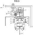
- FIG. 3 schematically shows the configuration of the storage mechanism 32.
- Banknotes transported along the transport path by the transport unit 23 are stored in the storage bag 34 by the storage mechanism 32.
- the storage bag 34 is mounted to the storage mechanism 32 in a state where an opening of the storage bag 34 is opened.
- Banknotes 100a that are sent into the storage bag 34 through the opening are stored in the storage bag 34 in a stacked state.
- rollers 72 and 74 are disposed opposed to each other at an inlet of the storage mechanism 32 through which banknotes are received from the transport unit 23.
- a banknote passes between the rollers 72 and 74.
- the storage mechanism 32 includes a sending unit 43 including a plurality of rollers and a plurality of belts.
- the sending unit 43 sends a banknote that has passed between the rollers 72 and 74, onto a gate member 44 (44L, 44R) as indicated by a dashed arrow.
- a plurality of banknotes 100b are accumulated on the gate member 44 in a stacked state.
- the gate member 44 serves as a partition member that separates the banknotes 100a that have already been stored in the storage bag 34, and the banknotes 100b that have not been stored in the storage bag 34, from each other.
- the gate member 44 serves as a temporary storage unit that temporarily stores the banknotes 100b before the banknotes 100b are stored in the storage bag 34.
- the gate member 44 includes a plurality of plate-shaped members 44L and 44R opposed to each other.
- the member shown at the left side in FIG. 3 is referred to as left member 44L
- the member shown at the right side in FIG. 3 is referred to as right member 44R.
- the left member 44L and the right member 44R are each supported at one end portion thereof by a shaft 44a. When the shafts 44a are rotated, the left member 44L and the right member 44R rotate.
- the left member 44L and the right member 44R each rotate about the shaft 44a, as indicated by an arrow, between a position indicated by solid lines and a position indicated by dashed lines as shown in FIG. 3 .
- the gate member 44 closes a passage leading to the storage bag 34 such that banknotes to be sent to the storage bag 34 cannot pass through the passage.
- the left member 44L and the right member 44R are normally biased by a spring member, which is not shown, so as to be located at the closed position where movement of banknotes along the passage is restricted.
- the upper surface of the left member 44L and the upper surface of the right member 44R form a flat surface that is a substantially horizontal plane.
- the gate member 44 When the gate member 44 is at the closed position, movement of banknotes moving toward the storage bag 34 is blocked, so that the banknotes cannot move along the passage leading to the storage bag 34 and are stacked on the gate member 44. That is, the upper surface of the gate member 44 serves as a stacking surface for banknotes.
- the gate member 44 opens the passage leading to the storage bag 34 such that banknotes to be sent to the storage bag 34 can pass through the passage.
- the opened position is a position where the left member 44L has rotated by substantially 90 degrees clockwise from the closed position and the right member 44R has rotated by substantially 90 degrees counterclockwise from the closed position.
- banknotes blocked from moving to the storage bag 34 by the gate member 44 can move toward the storage bag 34 again.
- the banknotes 100b stacked on the gate member 44 drop and are stored in the storage bag 34 located at the lower side of the gate member 44.
- Rotation of the left member 44L and the right member 44R to open the gate member 44 is performed by a gate member drive unit that is not shown.
- the left member 44L and the right member 44R move in conjunction with each other and open at the same time.
- the left member 44L and the right member 44R are connected by a connection mechanism that is not shown.
- the gate member drive unit drives the connection mechanism
- the left member 44L and the right member 44R open at the same time.
- the left member 44L and the right member 44R rotate by the same angles by the connection mechanism.
- the connection mechanism for moving the left member 44L and the right member 44R in conjunction with each other is configured, for example, by using a rack and a pinion.
- connection mechanism is configured by a plurality of members including at least one of a gear, a belt, and an arm.
- the connection mechanism for moving the members in conjunction with each other is a conventional technique, and thus the detailed description thereof is omitted.
- a pair of holding members 36 are disposed so as to be opposed to and spaced apart from each other.
- Each holding member 36 holds the vicinity of the opening of the storage bag 34. Whereas a position of the holding member 36 at the left side in FIG. 3 is fixed, the holding member 36 at the right side in FIG. 3 can move between a position shown in FIG. 3 and a position at which the holding member 36 at the right side is in contact with the holding member 36 at the left side.
- a heating member 37 for sealing the opening of the storage bag 34 is disposed at each of the left and right holding members 36. After a predetermined number of banknotes are stored in the storage bag 34 held by the holding members 36, one of the holding members 36 moves to a position at which the holding member 36 is in contact with the other holding member 36 with the opening of the storage bag 34 therebetween. In a state where the storage bag 34 is interposed between the two holding members 36, the heating members 37 apply heat to the storage bag 34 to thermally seal the opening.
- the storage mechanism 32 includes a pair of stages 40 for supporting the storage bag 34 held by the holding members 36, from below.
- the stages 40 are disposed so as to be movable in the up-down direction.
- the left and right stages 40 are connected by a hinge structure so as to be able to open and close. Opening/closing and up/down movement of the stages 40 are performed by a stage drive unit that is not shown.
- FIG. 3 shows a state where the left and right stages 40 are closed with the storage bag 34 interposed in the gap therebetween.
- the storage bag 34 held by the holding members 36 is brought into a state where a lower part thereof extends downward through the gap between the stages 40.
- a heating member 42 for thermally bonding the storage bag 34 is disposed at each of the left and right stages 40. After a predetermined number of banknotes are stored in the storage bag 34 held by the holding members 36, the left and right stages 40 move from positions where a gap is formed therebetween to closed positions where the stages 40 are in contact with each other with the storage bag 34 therebetween. In a state where the storage bag 34 is interposed between the two stages 40, the heating members 42 apply heat to a portion that is to be a bottom portion of the storage bag 34 having the banknotes stored therein, thereby thermally bonding the portion. The position where thermal bonding is performed by each heating member 42 is adjusted in accordance with the number of banknotes stored in the storage bag 34, by moving the stages 40 up or down.
- a pushing member 46 for pushing the banknotes 100b stacked on the gate member 44, into the storage bag 34, is disposed above the gate member 44.
- the pushing member 46 and the storage mechanism 32 are connected by a pantograph type link mechanism 47.
- the pushing member 46 moves in the up-down direction as indicated by an arrow in FIG. 3 , by the link mechanism 47. Movement of the pushing member 46 is performed by a pushing member drive unit that is not shown.
- a plurality of sensors 48 are disposed above the gate member 44.
- a sensor 48 including a light emitter and a light receiver is disposed so as to correspond to the left member 44L.
- the sensor 48 applies detection light from the light emitter to the left member 44L and receives the detection light reflected by the left member 44L, by the light receiver.
- another sensor 48 including a light emitter and a light receiver is disposed so as to correspond to the right member 44R.
- the sensor 48 applies detection light from the light emitter to the right member 44R and receives the detection light reflected by the right member 44R, by the light receiver.
- the money handling apparatus 1 detects presence/absence of the banknotes 100b stacked on the gate member 44, on the basis of a change in the detection light emitted and received by each sensor 48.
- the amount of the detection light received by each sensor 48 changes during the gate member 44 opens and closes in a state where there is no banknote thereon. It is because the direction of the detection light reflected by each of the left member 44L and the right member 44R is changed in accordance with the rotation position of each member 44L and 44R.
- the money handling apparatus 1 detects the positions of the left member 44L and the right member 44R, which open and close, on the basis of a change in the detection light emitted and received by each sensor 48.
- the money handling apparatus 1 detects whether or not the left member 44L and the right member 44R that have moved from the closed position to the opened position have returned to the closed position again when opening and closing the gate member 44. The detection method will be described in detail later.
- FIG. 4A and 4B illustrate a method for storing the banknotes 100b stacked on the gate member 44, into the storage bag 34.
- the banknotes 100b to be stored in the storage bag 34 are stacked on the gate member 44 that is at the closed position.
- the money handling apparatus 1 suspends stacking of banknotes onto the gate member 44 and opens the gate member 44 as indicated by arrows in FIG. 4A .
- the passage leading to the storage bag 34 is opened, so that the banknotes 100b can pass through the passage.
- the banknotes 100b stacked on the gate member 44 drop between the left member 44L and the right member 44R that have rotated to the opened position, due to the weights of the banknotes 100b, and are stored in the storage bag 34.
- the dropped banknotes 100b are stacked on the banknotes 100a as shown in FIG. 4A .
- the money handling apparatus 1 further pushes the banknotes 100b that have dropped into the storage bag 34, from above by the pushing member 46 to store the banknotes 100b into the storage bag 34.
- the pushing member drive unit that is not shown drives the link mechanism 47 having an upper end connected to the storage mechanism 32 to stretch in the up-down direction. Accordingly, the pushing member 46 connected to the lower end of the link mechanism 47 moves downward to push the banknotes 100b into the storage bag 34.
- the pushing member 46 moves downward to push the banknotes 100b into the storage bag 34 as shown in FIG. 4A , the pushing member 46 moves upward and returns to the original position as indicated by an arrow in FIG. 4B . After the pushing member 46 returns to the original position, the drive by the gate member drive unit is released, and the left member 44L and the right member 44R return to the closed position as indicated by arrows in FIG. 4B , by the bias force of the spring member.
- the money handling apparatus 1 stores the banknotes 100b stacked on the gate member 44, into the storage bag 34. After the money handling apparatus 1 stores the banknotes 100b into the storage bag 34, the money handling apparatus 1 detects whether or not there is any banknote that is not stored in the storage bag 34 and remains, by using the sensors 48.
- the money handling apparatus 1 restarts stacking of banknotes onto the gate member 44. Each time a predetermined number of banknotes are stacked on the gate member 44, the money handling apparatus 1 opens the gate member 44 and stores the banknotes into the storage bag 34 by the pushing member 46.
- the money handling apparatus 1 performs a retry process.
- a retry process an operation of opening the gate member 44 and pushing the banknote into the storage bag 34 by the pushing member 46 is performed.
- the money handling apparatus 1 confirms whether the remaining banknote has disappeared, by using the sensors 48. If it is confirmed that the remaining banknote has disappeared, the money handling apparatus 1 restarts stacking of banknotes onto the gate member 44. If it is confirmed that the remaining banknote is still there, the money handling apparatus 1 performs the retry process again. If the remaining banknote is repeatedly detected even when the retry process is performed a predetermined number of times that is set in advance, the money handling apparatus 1 determines that an error has occurred, and notifies the operator of the money handling apparatus 1 that the error has occurred. For example, the money handling apparatus 1 displays information indicating the occurrence of the error and information indicating that there is a remaining banknote, on the operation/display unit 29. The operator confirms the information displayed on the operation/display unit 29, removes the remaining banknote, and then restarts handling of banknotes.
- the money handling apparatus 1 changes the notification content on the basis of the number of banknotes stored in the storage bag 34.
- an uppermost banknote 100c among the banknotes 100b stored in the storage bag 34 may be in a standing state and caught between the left member 44L and the right member 44R returning from the opened position to the closed position, as indicated by a dashed arrow in FIG. 4B .
- a state where the banknote 100c is caught by the gate member 44 as described above is likely to occur.
- the number of banknotes that is close to the maximum number of banknotes that can be stored in the storage bag 34 is set as a threshold in advance. If the number of banknotes being stored in the storage bag 34 is smaller than the threshold when the sensors 48 detect any remaining banknote, the money handling apparatus 1 determines that the sensors 48 have detected a banknote on the gate member 44. In this case, the money handling apparatus 1 displays information indicating that there is a remaining banknote on the gate member 44, on the operation/display unit 29. If the number of banknotes being stored in the storage bag 34 is equal to or larger than the threshold when the sensors 48 detect any remaining banknote, the money handling apparatus 1 determines that the sensors 48 have detected a banknote caught between the left member 44L and the right member 44R.
- the money handling apparatus 1 displays information indicating that there is a remaining banknote caught by the gate member 44, on the operation/display unit 29.
- the operator can search for and remove the remaining banknote on the basis of the content displayed on the operation/display unit 29.
- the money handling apparatus 1 has one feature that, when there is the banknote 100c caught by the gate member 44 as shown in FIG. 4B , the banknote 100c can be accurately detected.
- the sensors 48 which are disposed above the gate member 44 as shown in FIG. 3 , detect any remaining banknote on the basis of a change in the amount of the detection light when the detection light applied to and reflected by the gate member 44 is blocked by the remaining banknote. For example, when a remaining banknote is caught by the gate member 44 in a state where a banknote surface thereof is almost vertical, there is a possibility that the detection light is not sufficiently blocked by the remaining banknote. Even in such a case, the money handling apparatus 1 can detect the remaining banknote on the basis of the positions of the left member 44L and the right member 44R.
- the gate member 44 has a structure in which, when a remaining banknote is caught between the left member 44L and the right member 44R, at least either one of the left member 44L and the right member 44R cannot return to the closed position. That is, when a remaining banknote is caught by the gate member 44, the remaining banknote blocks at least either one of the left member 44L and the right member 44R from returning to the closed position. Even when a remaining banknote caught by the gate member 44 is not directly detected by the sensors 48, any of the sensors 48 detects that at least either one of the left member 44L and the right member 44R has not returned to the closed position due to the presence of the remaining banknote.
- the money handling apparatus 1 can detect that there is a remaining banknote, on the basis of a detection result of the sensors 48.
- the structure of the gate member 44 and a method for detecting the position of the gate member 44 by the sensors 48 will be described.
- FIG. 5 illustrates the gate member 44.
- the gate member 44 includes the two members 44L and 44R each having a substantially rectangular plate shape. Irregularities are formed on the side surface of the members 44L and 44R.
- a banknote 100 sent from the transport unit 23 is stacked on the gate member 44 as indicated by a dotted line in FIG. 5 .
- the gate member 44 is configured to allow a banknote having a maximum length in the short edge direction thereof (Y axis direction), among a plurality of kinds of banknotes to be handled by the money handling apparatus 1, to be stacked on the gate member 44 in a flat shape without being bent.
- the gate member 44 is configured to allow a banknote having a maximum length in the long edge direction thereof (X axis direction), among the plurality of kinds of banknotes to be handled by the money handling apparatus 1, to be stacked on the gate member 44 in a flat shape without being bent.
- a plurality of projections 44d are formed in a comb shape over the entirety of one long edge side surface of each of the left member 44L and the right member 44R.
- a plurality of projected portions 44e each having a through hole for inserting the shaft 44a are formed on the other long edge side surface of each of the left member 44L and the right member 44R.
- Each projection 44d has a substantially rectangular parallelepiped shape projecting outward from the side surface of the member 44L or 44R.
- the left member 44L and the right member 44R are disposed opposed to each other.
- a plurality of projections 44d are formed on the long edge side surface, of the left member 44L, opposing the right member 44R, so as to project from the long edge side surface toward the right member 44R.
- a plurality of projections 44d are formed on the long edge side surface, of the right member 44R, opposing the left member 44L, so as to project from the long edge side surface toward the left member 44L.
- the projections 44d having the same shape are formed on the side surface of each of the members 44L and 44R at equal intervals in a row in the long edge direction.
- the projections 44d of the left member 44L and the projections 44d of the right member 44R have the same shape.
- the projections 44d of the left member 44L are formed at the same intervals as the projections 44d of the right member 44R.
- the projections 44d of the left member 44L and the projections 44d of the right member 44R are formed at different positions in the long edge direction so as to be shifted relative to each other as shown in FIG. 5 , when the left member 44L and the right member 44R are at the closed position.
- the projections 44d of the left member 44L and the projections 44d of the right member 44R do not overlap each other and are engaged in mesh with each other as shown in FIG. 5 , when the left member 44L and the right member 44R are at the closed position.
- the projections 44d formed in a comb shape on the long edge side surface of the left member 44L are arranged so as to fill the recessed spaces between the respective projections 44d formed in a comb shape on the long edge side surface of the right member 44R.
- the tips of the projections 44d of the left member 44L are located at the base side with respect to the tips of the projections 44d of the right member 44R.
- the positions of the tip ends of the projections 44d projecting in the Y axis negative direction from the long edge side surface of the left member 44L are at the Y axis negative direction side with respect to the positions of the tip ends of the projections 44d projecting in the Y axis positive direction from the long edge side surface of the right member 44R.
- each projection 44d of the left member 44L is located between two adjacent projections 44d of the right member 44R.
- a substantially horizontal flat surface having no step is formed by the upper surface of the left member 44L and the upper surface of the right member 44R, so that banknotes can be stacked on this flat surface.
- the projections 44d of the left member 44L and the projections 44d of the right member 44R which are arranged alternately in the long edge direction, are brought into mesh with each other, so that the gap between the left member 44L and the right member 44R is not linear but has a zigzag shape. Accordingly, a banknote sent from the transport unit 23 is prevented from dropping through the gap between the left member 44L and the right member 44R into the storage bag 34 located at the lower side (in the Z axis negative direction) of these members 44L and 44R.
- Each shaft 44a having an axis along the X axis direction is supported at both ends thereof by a side wall of the storage mechanism 32.
- the shaft 44a at the left member 44L and the shaft 44a at the right member 44R are connected by a connection mechanism such that the left member 44L and the right member 44R open in conjunction with each other.
- each shaft 44a is inserted through both through holes formed in a plurality of projected portions 32a of the side wall of the storage mechanism 32 and through holes formed in the projected portions 44e formed on the long edge side surface of the gate member 44.
- the projected portions 44e of the gate member 44 are inserted between the projected portions 32a of the storage mechanism 32, so that the gap between the long edge side surface of the gate member 44 and the storage mechanism 32 is not linear. Accordingly, a banknote sent from the transport unit 23 is prevented from dropping downward through the gap between the gate member 44 and the storage mechanism 32.
- a plurality of projected portions 44c for closing the gap between the storage mechanism 32 and the gate member 44 are formed on short edge side surfaces of the gate member 44.
- the projected portions 44c are formed on both the short edge side surface at the upper side shown in FIG. 5 and the short edge side surface at the lower side shown in FIG. 5 . Accordingly, a banknote sent from the transport unit 23 is prevented from dropping downward through the gap between each short edge side surface of the gate member 44 and the storage mechanism 32.
- a plurality of detection areas 44b are formed on the upper surface of the gate member 44. Specifically, a plurality of detection areas 44b are formed on the upper surface of the left member 44L, and a plurality of detection areas 44b are also formed on the upper surface of the right member 44R.
- the detection areas 44b reflect the detection light applied from the sensors 48.
- the detection areas 44b are each formed by attaching a mirror-finished flat member to the gate member 44.
- FIG. 6 illustrates the arrangement of the sensors 48.
- the sensors 48 include a light emitter and a light receiver
- the sensors 48 are disposed so as to correspond to the respective detection areas 44b formed on the gate member 44, respectively.
- Each sensor 48 is disposed such that detection light applied from the light emitter and reflected by the detection area 44b is received by the light receiver as indicated by a dotted line in FIG. 6 .
- Each detection area 44b is formed at a position that is covered by the banknote 100 when the banknote 100 is stacked on the upper surface of the gate member 44 as indicated by the dotted line in FIG. 5 .
- the money handling apparatus 1 detects presence/absence of the banknote 100 stacked on the gate member 44, on the basis of a change in the amount of detection light due to blocking of the detection light, which is emitted and received by the sensors 48, by the banknote 100.
- Some banknotes may include a transparent area that transmits light. When the transparent area of the banknote 100 stacked on the gate member 44 coincides with the detection areas 44b, there is a possibility that the detection light is not blocked by the banknote 100 and the banknote 100 cannot be detected on the basis of a change in the amount of detection light. Even when the detection light passes through the transparent area of the banknote 100 at some of the detection areas 44b, the money handling apparatus 1 can detect the banknote 100 by the detection light at the other detection areas 44b.
- the money handling apparatus 1 can detect the banknote 100c by the corresponding sensor 48. Depending on the state of the banknote 100c, there is a possibility that none of the detection areas 44b is covered. However, in such a case as well, the money handling apparatus 1 can detect that there is the banknote 100c, on the basis of the position of the gate member 44.
- FIGS. 7A to 7C illustrate a method for detecting a banknote caught by the gate member 44.
- the projections 44d of the left member 44L and the right member 44R that are at the closed position are engaged in mesh with each other, and the left member 44L and the right member 44R overlap each other by a width Wa in the lateral direction (Y axis direction) when being seen from the longitudinal direction (X axis direction).
- Y axis direction the lateral direction
- X axis direction longitudinal direction
- the right member 44R can return to the closed position, but the left member 44L cannot return to the closed position due to the presence of the caught banknote 100.
- the left member 44L stops at a position where the left member 44L slightly rotates from the closed position toward the opened position.
- the detection light applied from the sensors 48 to the detection areas 44b of the left member 44L is reflected at a position 82 shown in FIG. 7C .
- the gate member 44 is configured such that the amount of the detection light emitted and received by the sensors 48 changes between when the gate member 44 is at the closed position and when the gate member 44 is in the state shown in FIG. 7C .
- a distance d shown in FIG. 7C is set to a distance that allows the sensors 48 to detect a change in the amount of the detection light.
- An angle ⁇ is set on the basis of the distance d, and the overlap width Wa of the projections 44d and the thickness t of each projection 44d are set on the basis of the angle ⁇ .
- the angle ⁇ formed by the lower surface of the right member 44R and the upper surface of the left member 44L is determined by the overlap width Wa and the thickness t of the projections 44d of the left member 44L and the right member 44R.
- the distance d is determined by the angle ⁇ and the position 82 at which the detection light is reflected. If the distance d is too small, a change in the amount of the detection light emitted and received by the sensors 48 is too small, and it cannot be detected that the left member 44L has not returned to the closed position.
- the distance d is set to a distance that allows the sensors 48 to detect that the left member 44L has not returned to the closed position.
- the dimensions and the shapes of the left member 44L and the right member 44R including the overlap width Wa and the thickness t are set such that the distance d is realized.
- the sensors 48 detect that the left member 44L has not returned to the closed position, on the basis of a change in the amount of the detection light applied to and reflected by the gate member 44. Accordingly, the money handling apparatus 1 can detect that there is a banknote 100 caught by the gate member 44.
- FIG. 7C shows the case where the banknote 100 is caught between the upper surface of the left member 44L and the lower surface of the right member 44R, but the banknote 100 may be caught between the lower surface of the left member 44L and the upper surface of the right member 44R.
- the money handling apparatus 1 can detect that the right member 44R has not returned to the closed position, on the basis of a change in the detection light emitted and received by the sensors 48 with respect to the detection areas 44b of the right member 44R. Accordingly, the money handling apparatus 1 can detect that there is a banknote 100 caught by the gate member 44.
- a banknote may be caught with the left member 44L located at the lower side than the right member 44R, or a banknote may be caught with the right member 44R located at the lower side than the left member 44L. It is possible to configure the gate member 44 such that a banknote is caught with the same one member located at the lower side than the other member. A specific description will be given with the case where a banknote is caught with the right member 44R located at the lower side, as an example.
- FIGS. 8A to 8C show the configuration of the gate member 44 by which the banknote 100 is caught with the right member 44R located at the lower side.
- the length in the short edge direction of the right member 44R is longer than that of the left member 44L.
- a length La from the axis of the shaft 44a about which the right member 44R rotates to the tip end of the projection 44d of the right member 44R is longer than a length Lb from the axis of the shaft 44a about which the left member 44L rotates to the tip end of the projection 44d of the left member 44L (La > Lb).
- the left member 44L and the right member 44R rotate by the same angles at the same timings and return to the closed position by the bias force of the spring member.
- FIG. 8B when the left member 44L and the right member 44R return by the same angle from the closed position, the tips of the projections 44d of the right member 44R are located below the tips of the projections 44d of the left member 44L in the up-down direction.
- the banknote 100 between the left member 44L and the right member 44R is caught between the projections 44d of the left member 44L and the projections 44d of the right member 44R that are located below the projections 44d of the left member 44L.
- the gate member 44 is closed as shown in FIG. 8C , the banknote 100 is caught between the lower surface of the left member 44L that has returned to the closed position and the upper surface of the right member 44R that cannot return to the closed position.
- the one member 44R is always located at the lower side when the banknote 100 is caught between members 44L and 44R as described above, it is preferable to use sensors that detect with high accuracy the banknote 100 stacked on the member 44R and the position of the member 44R that cannot return to the closed position.
- the number of sensors for the right member 44R is increased as compared to the number of sensors for the left member 44L.
- sensors having higher performance than the sensors for the left member 44L are used for the right member 44R. Accordingly, the banknote 100 caught between the left member 44L and the right member 44R can be detected with higher accuracy.
- the overlap width Wa of the left member 44L and the right member 44R shown in FIGS. 7A to 7C and FIGS. 8A to 8C changes depending on the shapes of the projections 44d.
- FIG. 9 shows the structure of the projections 44d.
- the overlap width Wa of the projections 44d shown in FIG. 9 is set to about 6 mm
- a gap Wb in the short edge direction between the left member 44L and the right member 44R is set to about 2 mm.
- a length Lc in the long edge direction of each projection 44d is set to about 6 mm
- each gap Ld in the long edge direction between the projections 44d of the left member 44L and the projections 44d of the right member 44R is set to about 3 mm.
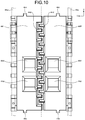
- FIG. 10 shows a specific structure example of the gate member 44.
- the projections 44d of the left member 44L and the projections 44d of the right member 44R shown in FIG. 10 are chamfered.
- the cross-sectional shape of each projection 44d seen from the short edge side (Y axis direction) is a trapezoidal shape in which the upper side is smaller than the lower side.
- the long edge side surface connecting two adjacent projections 44d is also chamfered similar to the projections 44d.
- FIG. 11 shows a side shape of the gate member 44 shown in FIG. 10 .
- the upper drawing of FIG. 11 is a view of the gate member 44 shown in FIG. 10 as seen from the long edge direction (X axis negative direction).
- the left member 44L and the right member 44R are disposed such that the tips of the projections 44d thereof overlap each other in the width direction (Y axis direction) when being seen from the long edge direction.
- Y axis direction width direction
- a length L1 from the axis of the shaft 44a of the right member 44R to the tip end of the projection 44d of the right member 44R is longer than a length L3 from the axis of the shaft 44a of the left member 44L to the tip end of the projection 44d of the left member 44L (L1 > L3).
- the length L1 of the right member 44R is longer than the length L3 of the left member 44L by a few millimeters.
- a length L2 from a center line between the axis of the shaft 44a of the right member 44R and the axis of the shaft 44a of the left member 44L to the tip end of the projection 44d of the right member 44R is longer than a length L4 from the center line to the tip end of the projection 44d of the left member 44L (L2 > L4).
- FIGS. 12A and 12B show a state where the banknote 100 is caught by the gate member 44 shown in FIG. 10 and FIG. 11 .
- FIG. 12A shows the case where the banknote 100 is caught with the left member 44L located at the lower side
- FIG. 12B shows the case where the banknote 100 is caught with the right member 44R located at the lower side.
- the length L1 shown in FIG. 11 is set to about 55.5 mm
- the length L3 shown in FIG. 11 is set to about 51.5 mm
- the length L2 shown in FIG. 11 is set to about 4.5 mm
- the length L4 shown in FIG. 11 is set to about 1.5 mm
- the thickness t of the projections 44d shown in FIG. 11 is set to about 7 mm.
- angles ⁇ 1 and ⁇ 2 shown in FIGS. 12A and 12B are each about 8 degrees, and can be detected by the sensors 48 when the banknote 100 is caught and the left member 44L or the right member 44R cannot return to the closed position.
- 12A and 12B respectively show the case where the banknote 100 is caught with the left member 44L located at the lower side and the case where the banknote 100 is caught with the right member 44R located at the lower side, since the length L1 of the right member 44R is longer than the length L3 of the left member 44L, the banknote 100 is normally caught with the right member 44R located at the lower side as shown in FIG. 12B .
- FIG. 6 shows the example in which whether or not the left member 44L and the right member 44R that have rotated to the opened position have returned to the closed position is detected by using the sensors 48 that is also used for detecting presence/absence of any banknote stacked on the gate member 44, but the usage of sensors is not limited thereto.
- a sensor for detecting any banknote caught by the gate member 44 may be disposed.
- FIG. 13 shows an example in which sensors 51 and 52 that emit and receive detection light in the short edge direction of the gate member 44 are disposed.
- FIG. 13 shows a state where a banknote is caught between the left member 44L and the right member 44R, although the caught banknote is not shown in FIG. 13 for easy explanation.
- the sensor 51 is disposed such that the detection light passes slightly above the upper surface of the gate member 44 at the closed position and passes substantially parallel to the upper surface. Accordingly, if a part of the banknote caught by the gate member 44 is located above the upper surface of the gate member 44 at the closed position, the money handling apparatus 1 can detect the caught banknote by the sensor 51.
- FIG. 13 shows one sensor 51, but, when a plurality of sensors 51 are disposed so as to be spaced apart from each other in the X axis direction, the detection accuracy is further improved.
- the sensor 52 is disposed such that the detection light passes slightly below the lower surfaces of the projections 44d at the closed position and passes substantially parallel to the upper surface of the gate member 44 at the closed position. Accordingly, if a part of the banknote caught by the gate member 44 is located below the lower surfaces of the projections 44d of the gate member 44 at the closed position, the money handling apparatus 1 can detect the caught banknote by the sensor 52.
- the projections 44d of the right member 44R that cannot return to the closed position due to the caught banknote block the detection light of the sensor 52 as shown in FIG. 13 , and therefore it enables the money handling apparatus 1 to detect that there is the banknote caught by the gate member 44.
- FIG. 13 shows one sensor 52, but, when a plurality of sensors 52 are disposed so as to be spaced apart from each other in the X axis direction, the detection accuracy is further improved.
- FIGS. 14A to 14C show an example in which sensors 53 and 54 that emit and receive detection light in the long edge direction of the gate member 44 are disposed.
- FIG. 14A shows the gate member 44 at the closed position.
- FIGS. 14B and 14C each show a state where a banknote is caught between the left member 44L and the right member 44R, although the caught banknote is not shown in FIGS. 14B and 14C for easy explanation.
- the sensors 53 and 54 are disposed such that the detection light passes slightly below the lower surfaces of the projections 44d and passes substantially parallel to the upper surface of the gate member 44 at the closed position.
- the detection light by the sensor 53 is emitted and received at a position overlapping the projections 44d of the left member 44L that cannot return to the closed position due to the caught banknote.
- the detection light by the sensor 54 is emitted and received at a position overlapping the projections 44d of the right member 44R that cannot return to the closed position due to the caught banknote.
- the money handling apparatus 1 can detect the caught banknote by the sensor 53 or 54.
- the projections 44d of the left member 44L or the right member 44R that cannot return to the closed position due to the caught banknote block the detection light of the sensor 53 or 54, and therefore it enables the money handling apparatus 1 to detect that there is the banknote caught by the gate member 44.
- FIG. 5 to FIG. 14C show examples in which the projections 44d having the same shape which is a substantially rectangular parallelepiped shape are formed in a comb shape in a row at equal intervals on each of the opposing side surfaces of the left member 44L and the right member 44R, but the configurations of the projections 44d are not limited thereto.
- the shapes of the projections 44d are not particularly limited, as long as: any banknote does not drop downward through the gap of the gate member 44 when the gate member 44 is at the closed position; and a component of the gate member 44 that cannot return to the closed position when a banknote is caught by the gate member 44 can be detected.
- FIGS. 15A to 15D each show an example of projections 144a and 144b having different shapes.
- the projections 144a and 144b are not limited to those all having the same length in the long edge direction. Some of the projections 144a and 144b may have different lengths in the long edge direction as shown in FIG. 15A .
- the projections 144a and 144b are not limited to those all having the same length in the short edge direction, and some of the projections 144a and 144b may have different lengths in the short edge direction.
- the projection 144a of a left member 144L and the projections 144b of the right member 144R are not limited to those all in mesh with each other at the closed position.
- the left member 144L and the right member 144R may include projections 144c that are not engaged in mesh with each other at the closed position as shown in FIG. 15B .
- each projection is not limited to a substantially rectangular parallelepiped shape.
- the shapes of the projections 144a and 144b as seen from above may include curved lines, for example, as shown in FIG. 15C .
- the shapes of the projections 144a and 144b as seen from the short edge side may include curved lines.
- the projections 144a of the left member 144L and the projections 144b of the right member 144R are not limited to those arranged alternately one by one in the long edge direction.
- a plurality of projections 144a of the left member 144L may be arranged consecutively, and then a plurality of projections 144b of the right member 144R may be arranged consecutively.
- FIG. 16 shows an example of a gate member 244 (244L, 244R) having different shapes.
- a length Wa in the short edge direction of each projection 244a may be longer than a length Wc in the short edge direction of a body portion 244b connecting the projections 244a formed in a comb shape.
- the method for opening and closing the gate member is also not limited to a method in which two members, a left member and a right member, disposed opposed to each other rotate to open and close the gate member.
- the gate member may be opened or closed by translating the two members, i.e., the left member and the right member, such that mesh of projections of the two members is released.
- FIGS. 17A to 17C show an example of the gate member 244 that is opened and closed by moving parallel in a horizontal direction.
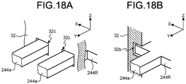
- FIGS. 18A and 18B show a part of the gate member 244 and a part of the storage mechanism 32 shown in FIGS. 17A to 17C .
- through holes 32c are formed in the side wall, which is parallel to the long edge direction (X axis direction), of the storage mechanism 32. Positions of the through holes 32c match with positions of projections 244a of the gate member 244, respectively.
- grooves 32b are formed on the side wall, which is parallel to the short edge direction (Y axis direction), of the storage mechanism 32. Positions of the grooves 32b match with positions of the short edge side surface of the gate member 244 such that the gate member 244 can move in the short edge direction.
- the gate member 244 In a state where the projections 244a are inserted into the through holes 32c of the long edge side wall of the storage mechanism 32, the gate member 244 is supported so as to be movable along the grooves 32b of the short edge side wall of the storage mechanism 32. Accordingly, a banknote is prevented from dropping downward through the gap between the gate member 244 and the storage mechanism 32.
- banknotes 100 sent by the transport unit 23 are stacked on the gate member 244 at a closed position where the projections 244a of the left member 244L and the projections 244a of the right member 244R are engaged in mesh with each other.
- the left member 244L and the right member 244R are biased to the closed position by a spring member that is not shown.
- a gate member drive unit which is not shown, drives the gate member 244 to slide and open as indicated by arrows in FIG. 17C .
- the left member 244L slides along the groove 32b to the left of the drawing
- the right member 244R slides along the groove 32b to the right of the drawing.
- a sensor 151 that emits and receives detection light in the long edge direction are disposed at the left side of the left member 244L.
- Another sensor 152 that emits and receives detection light in the long edge direction is disposed at the right side of the right member 244R.
- the detection light of the sensor 151 is blocked by the left member 244L.
- the detection light of the sensor 152 is blocked by the right member 244R.
- the left member 244L and the right member 244R return to the closed position by the bias force of the spring member after moving to the opened position, the detection light of the sensors 151 and 152 returns to the transmitted state.
- the money handling apparatus 1 can detect presence/absence of any banknote caught by the gate member 244, on the basis of a change between transmission and blocking of the detection light.
- the sensor arrangement is not limited to the example shown in FIG. 17A .
- sensors 153 and 154 that emit and receive detection light in the up-down direction may be used as shown in FIGS. 17B and 17C .
- the sensor 153 that emits and receives detection light in the up-down direction is disposed at the left side of the left member 244L so as to correspond to the position where the projections 244a of the left member 244L pass when opening and closing the gate member 244.
- the sensor 154 that emits and receives detection light in the up-down direction is disposed at the right side of the right member 244R so as to correspond to the position where the projections 244a of the right member 244R pass when opening and closing the gate member 244.
- the detection light of the sensors 153 and 154 are in a transmitted state.
- the detection light of the sensors 153 and 154 is blocked by the body portion 244b or the projections 244a to be brought into a blocked state.
- the detection light of the sensors 153 and 154 returns to the transmitted state again. If a banknote is caught between the left member 244L and the right member 244R, the left member 244L and the right member 244R cannot return to the closed position and therefore, the detection light of the sensors 153 and 154 is kept in the blocked state.
- the money handling apparatus 1 can detect presence/absence of any banknote caught by the gate member 244, on the basis of a change between transmission and blocking of the detection light.
- the positions of the members that form the gate member 44, 144, or 244 are detected by the optical sensors that emit and receive detection light.
- the types of the sensors are not particularly limited as long as whether or not the gate member 44, 144, or 244 has returned to the closed position can be detected.
- a sensor for mechanically detecting the position of each member may be used.
- the detection method is not limited to use of a single method, and a plurality of types of detection methods may be used in combination.
- the gate member 44, 144, or 244 opens and closes the banknote passage leading to the storage bag 34.
- the use of the gate member 44, 144, or 244 is not limited thereto.
- each process can be performed as described above.
- each process can be performed as described above.
- the gate member 44, 144, or 244 can be used as described above for performing a temporary storage process for temporarily storing banknotes before storing the banknotes into a storage unit or a storage container.
- the configurations of the money handling apparatus 1, the banknote handling unit 20, and the storage mechanism 32 described in the present embodiment are illustrative, and the configuration of each component is not particularly limited as long as a remaining banknote caught by the gate member 44, 144, or 244 can be detected as describe above.
- the configuration of the storage bag 34 is not particularly limited, and the components that hold, support, and seal the storage bag 34 may have configurations different from those shown in FIG. 3 .
- the money handling apparatus includes: a storage configured to store money therein; a gate member configured to open and close a passage leading to the storage by moving between a closed position to restrict movement of money along the passage, and an opened position to allow the money to move along the passage; and a detection unit configured to detect presence/absence of money caught by the gate member.
- the detection unit detects presence/absence of the money caught by the gate member, on the basis of a position of the gate member.
- the gate member rotates between the opened position and the closed position.
- movement of the gate member between the opened position and the closed position is parallel movement with respect to a horizontal direction.
- the gate member includes a first member and a second member disposed opposed to each other, the first member and the second member have shapes with which at least either one of the first member and the second member is blocked from returning to the closed position when money is caught between the first member and the second member while the first member and the second member are moving from the opened position to the closed position, and the detection unit detects that at least either one of the first member and the second member does not return to the closed position when the gate member moves from the opened position to the closed position.
- the first member has, on a side surface opposing the second member, a plurality of projections projecting from the side surface toward the second member
- the second member has, on a side surface opposing the first member, a plurality of projections projecting from the side surface toward the first member
- the projections of the first member and the projections of the second member are formed at positions that allow the projections of the first member and the projections of the second member to be engaged with each other at the closed position.
- a tip of at least one projection of the first member is located at a base side with respect to a tip of at least one projection of the second member when the gate member is at the closed position.
- the first member includes at least one set of two projections adjacent to each other between which at least one projection of the second member interposed therebetween in a state where the gate member is at the closed position.
- the gate member has a stacking surface on which money is stacked when the gate member is at the closed position, and the detection unit detects presence/absence of money stacked on the stacking surface.
- the gate member has a stacking surface on which money is stacked when the gate member is at the closed position, and, when the gate member moves to the opened position, money stacked on the stacking surface is stored in the storage located below the stacking surface.
- the detection unit includes a sensor configured to emit detection light to the gate member and receive the detection light reflected by the gate member.
- the detection unit includes a sensor configured to emit and receive detection light, and the sensor is disposed at a position that allows the detection light to be blocked by money caught by the gate member or the gate member when the gate member opens and closes.
- the detection unit includes a light emitter configured to emit the detection light and a light receiver configured to receive the detection light and the light receiver is disposed at a position at which, when money is caught by the gate member, the light receiver opposes the light emitter with the caught money therebetween.
- the detection unit includes a sensor configured to mechanically detect a change in a position of the gate member.
- the gate member rotates about a rotation shaft between the closed position and the opened position
- the detection unit includes a sensor configured to detect a rotation angle of the gate member
- the detection unit includes a camera configured to take an image of the gate member.
- the money handling method includes: closing by a gate member a passage leading to a storage configured to store money therein, such that movement of money is restricted; opening by the gate member the passage, such that money moves along the passage; and detecting by a detection unit presence/absence of money caught by the gate member, after opening and closing of the gate member.
- the money handling apparatus includes, on a passage through which money moves, a gate member that opens and closes the passage. After the gate member is opened to move money, money that cannot move and remains can be detected. For example, when money is caught by the gate member while the gate member is moving between the closed position and the opened position, the money handling apparatus can detect the remaining money by a sensor.
- the gate member includes a member that does not return to the closed position when money is caught by the gate member.
- the money handling apparatus can detect presence/absence of remaining money by detecting the member that does not return to the closed position with use of a sensor. That is, even when remaining money caught by the gate member cannot be directly detected, the money handling apparatus can indirectly detect the remaining money on the basis of the position of the gate member. Accordingly, the money handling apparatus can detect presence/absence of remaining money with higher accuracy than in the conventional art.
- the money handling apparatus and the money handling method according to the present embodiment are useful for detecting money that cannot move and remains upon moving money in the apparatus, with high accuracy.
Landscapes
- Engineering & Computer Science (AREA)
- Mechanical Engineering (AREA)
- Pile Receivers (AREA)
Abstract


Description
- The present invention relates to a money handling apparatus and a money handling method for detecting money that is to be moved but cannot move and remains in the apparatus.
- Conventionally, money handling apparatuses that store money therein have been used. Such a money handling apparatus transports money inside the apparatus. For example, money moves in the apparatus and is stored in a storage unit fixed in the apparatus or a storage container detachably mounted to the apparatus. For example, a cassette or a bag is used as the storage container for money. It is necessary to reliably transport all money to be moved in order to strictly manage all the money in the money handling apparatus. The money handling apparatus performs detection of money that cannot move and remains, by a sensor, in order to confirm that all money has moved.
- Japanese Laid-Open Patent Publication No.
2016-162435 - Even when the conventional art described above is used, however, remaining banknotes cannot be detected in some cases. For example, when banknotes are to be moved inside an apparatus, there are cases where any banknote becomes caught by a component of the apparatus, cannot move, and remains in the apparatus. In some cases, the remaining banknote blocks only a part of the detection light depending on the position or the shape of the banknote, and a change in the detection light cannot be detected in some cases.
- The present invention has been made in view of the problem of the conventional art, and an object of the present invention is to provide a money handling apparatus and a money handling method that enable detection of money that is to be moved but cannot move and remains in the apparatus.
- To solve the above-described problem and achieve the above-described object, a money handling apparatus according to one aspect of the present invention provides includes: a storage configured to store money therein; a gate member configured to open and close a passage leading to the storage by moving between a closed position to restrict movement of money along the passage and an opened position to allow the money to move along the passage; and a detection unit configured to detect presence/absence of money caught by the gate member.
- The money handling apparatus includes a passage for moving money, and a gate member configured to open and close the passage. If there is money that cannot pass through the position at which the gate member is disposed and that is caught by the gate member, the detection unit detects the caught money. Accordingly, the money handling apparatus can detect money that cannot move and remains when money moves in the path.
-
-
FIG. 1 shows the outer appearance of a money handling apparatus according to an embodiment; -
FIG. 2 schematically shows the internal configuration of a banknote handling unit; -
FIG. 3 schematically shows the configuration of a storage mechanism; -
FIG. 4A and 4B illustrate a method for storing banknotes stacked on a gate member, into a storage bag; -
FIG. 5 illustrates the gate member. -
FIG. 6 illustrates arrangement of sensors; -
FIGS. 7A to 7C illustrate a method for detecting a banknote caught by the gate member; -
FIGS. 8A to 8C show the configuration of the gate member by which a banknote is caught with a right member located at the lower side; -
FIG. 9 shows the structure of projections; -
FIG. 10 shows a specific structure example of the gate member; -
FIG. 11 shows a side surface shape of the gate member shown inFIG. 10 ; -
FIGS. 12A and 12B show a state where a banknote is caught by the gate member shown inFIG. 10 andFIG. 11 ; -
FIG. 13 shows an example in which sensors that emit and receive detection light in the short edge direction of the gate member are disposed; -
FIGS. 14A to 14C show an example in which sensors that emit and receive detection light in the long edge direction of the gate member are disposed; -
FIGS. 15A to 15D each show an example of projections having different shapes; -
FIG. 16 shows an example of a gate member having a different shape; -
FIGS. 17A to 17C show an example of a gate member that opens and closes by moving parallel to a horizontal direction; and -
FIGS. 18A and 18B show a part of the gate member and the storage mechanism shown inFIGS. 17A to 17C . - Hereinafter, an embodiment of the money handling apparatus and the money handling method according to the present invention will be described with reference to the accompanying drawings. First, the configuration of the money handling apparatus will be described.
FIG. 1 shows the outer appearance of a money handlingapparatus 1 according to the present embodiment. In the drawings showing the configuration of themoney handling apparatus 1 in the present embodiment, three axes of X, Y, and Z orthogonal to each other are shown such that the relationship between the parts shown in each drawing can be understood. The X axis indicates the width direction of the money handling apparatus 1 (right-left direction), the Y axis indicates the depth direction of the money handling apparatus 1 (front-rear direction), and the Z axis indicates the up-down direction. - The
money handling apparatus 1 includes acoin handling unit 10 and abanknote handling unit 20. Thecoin handling unit 10 performs coin handling including depositing and dispensing of coins. Thebanknote handling unit 20 performs banknote handling including depositing and dispensing of banknotes. In depositing, coins are deposited from a depositingunit 11 of thecoin handling unit 10, and banknotes are deposited from a depositingunit 21 of thebanknote handling unit 20. Coins that cannot be deposited in theapparatus 1 are returned from anexternal reject unit 17, and banknotes that cannot be deposited in theapparatus 1 are returned from anexternal reject unit 27. In dispensing, coins are dispensed from a dispensingunit 12 of thecoin handling unit 10, and banknotes are dispensed from a dispensingunit 22 of thebanknote handling unit 20. - The
money handling apparatus 1 includes an operation/display unit 29. The operation/display unit 29 is, for example, a touch panel type liquid crystal display device. The operation/display unit 29 serves as a display unit that displays information of coins handled by thecoin handling unit 10 and information of banknotes handled by thebanknote handling unit 20. The operation/display unit 29 also serves as an operation unit for an operator of themoney handling apparatus 1 to input various kinds of information to theapparatus 1. The configurations of themoney handling apparatus 1, thecoin handling unit 10, and thebanknote handling unit 20 and processes performed by the respective apparatus and units are disclosed, for example, in Japanese Laid-Open Patent Publication No.2018-181137 -
FIG. 2 schematically shows the internal configuration of thebanknote handling unit 20. As shown inFIG. 1 andFIG. 2 , thebanknote handling unit 20 includes the depositingunit 21, the dispensingunit 22, theexternal reject unit 27, aninternal reject unit 28, atransport unit 23, arecognition unit 24, and a plurality ofstorage units 25. Thebanknote handling unit 20 further includes astorage bag 34 that is detachably mounted to thebanknote handling unit 20, and astorage mechanism 32 that stores banknotes into thestorage bag 34. - In depositing, the depositing
unit 21 receives banknotes to be deposited, and feeds the banknotes into the unit one by one. Thetransport unit 23 transports the banknotes fed by the depositingunit 21, along a transport path. Therecognition unit 24 recognizes and counts the banknotes transported on the transport path. For example, therecognition unit 24 recognizes denomination, fitness, and authenticity of each banknote and counts the number of banknotes for each denomination and the total monetary amount of all the banknotes. Thetransport unit 23 transports the banknotes to any of thestorage units 25, theexternal reject unit 27, and thestorage mechanism 32 on the basis of the result of recognition by therecognition unit 24. A kind of banknote to be stored can be set for eachstorage unit 25. For example, the denomination of banknotes to be stored in eachstorage unit 25 is set. - Banknotes that are determined not to be able to be deposited as a result of recognition by the
recognition unit 24 are discharged as reject banknotes from theexternal reject unit 27. For example, banknotes that cannot be recognized by therecognition unit 24, and banknotes that are recognized as counterfeit banknotes by therecognition unit 24 are discharged from theexternal reject unit 27. On the other hand, banknotes that can be deposited are stored in thestorage unit 25 corresponding to the kind of the banknotes, on the basis of the result of recognition. For example, banknotes are stored in thestorage units 25 for each denomination. - When the
storage unit 25 is filled with banknotes to a full state and any other banknote cannot be stored thereinto, the banknote is transported to thestorage mechanism 32 and stored in thestorage bag 34. A kind of banknote that can be deposited but is not set for anystorage unit 25 is also transported to thestorage mechanism 32 and stored in thestorage bag 34. In addition, thestorage bag 34 is also used for collection in which banknotes being stored in thestorage units 25 are collected to take out to the outside of theunit 20. Specifically, banknotes to be collected are fed out from thestorage units 25, transported to thestorage mechanism 32, and stored in thestorage bag 34. Thestorage mechanism 32 is configured such that thestorage bag 34 is mountable and dismountable with respect to thestorage mechanism 32. A person in charge of the collection can dismount thestorage bag 34 from thestorage mechanism 32 and collect banknotes being stored in thestorage bag 34, together with thebag 34. - In dispensing, banknotes to be dispensed are fed out from the
storage units 25. Thetransport unit 23 transports the fed-out banknotes along the transport path. A sensor for detecting a banknote transport state is disposed on the transport path. When the sensor detects that a plurality of banknotes are transported while overlapping each other (double feed), if these banknotes are dispensed, the number of dispensed banknotes cannot be determined. Thus, banknotes for which overlapping has been detected are determined not to be able to be dispensed and are stored in theinternal reject unit 28. Banknotes that can be dispensed are dispensed from the dispensingunit 22. - Next, the
storage mechanism 32 that stores banknotes into thestorage bag 34 will be described.FIG. 3 schematically shows the configuration of thestorage mechanism 32. Banknotes transported along the transport path by thetransport unit 23 are stored in thestorage bag 34 by thestorage mechanism 32. As shown inFIG. 3 , thestorage bag 34 is mounted to thestorage mechanism 32 in a state where an opening of thestorage bag 34 is opened.Banknotes 100a that are sent into thestorage bag 34 through the opening are stored in thestorage bag 34 in a stacked state. - As shown in
FIG. 3 ,rollers storage mechanism 32 through which banknotes are received from thetransport unit 23. A banknote passes between therollers storage mechanism 32 includes a sendingunit 43 including a plurality of rollers and a plurality of belts. The sendingunit 43 sends a banknote that has passed between therollers banknotes 100b are accumulated on thegate member 44 in a stacked state. - The
gate member 44 serves as a partition member that separates thebanknotes 100a that have already been stored in thestorage bag 34, and thebanknotes 100b that have not been stored in thestorage bag 34, from each other. Thegate member 44 serves as a temporary storage unit that temporarily stores thebanknotes 100b before thebanknotes 100b are stored in thestorage bag 34. - The
gate member 44 includes a plurality of plate-shapedmembers FIG. 3 is referred to asleft member 44L, and the member shown at the right side inFIG. 3 is referred to asright member 44R. Theleft member 44L and theright member 44R are each supported at one end portion thereof by ashaft 44a. When theshafts 44a are rotated, theleft member 44L and theright member 44R rotate. Theleft member 44L and theright member 44R each rotate about theshaft 44a, as indicated by an arrow, between a position indicated by solid lines and a position indicated by dashed lines as shown inFIG. 3 . - In a closed position where the
left member 44L and theright member 44R are located at the positions indicated by the solid lines inFIG. 3 , thegate member 44 closes a passage leading to thestorage bag 34 such that banknotes to be sent to thestorage bag 34 cannot pass through the passage. Theleft member 44L and theright member 44R are normally biased by a spring member, which is not shown, so as to be located at the closed position where movement of banknotes along the passage is restricted. When theleft member 44L and theright member 44R are at the closed position, the upper surface of theleft member 44L and the upper surface of theright member 44R form a flat surface that is a substantially horizontal plane. When thegate member 44 is at the closed position, movement of banknotes moving toward thestorage bag 34 is blocked, so that the banknotes cannot move along the passage leading to thestorage bag 34 and are stacked on thegate member 44. That is, the upper surface of thegate member 44 serves as a stacking surface for banknotes. - In an opened position where the
left member 44L and theright member 44R are located at the positions indicated by the dashed lines inFIG. 3 , thegate member 44 opens the passage leading to thestorage bag 34 such that banknotes to be sent to thestorage bag 34 can pass through the passage. The opened position is a position where theleft member 44L has rotated by substantially 90 degrees clockwise from the closed position and theright member 44R has rotated by substantially 90 degrees counterclockwise from the closed position. When theleft member 44L and theright member 44R are at the opened position, the upper surfaces of theleft member 44L and theright member 44R, which are substantially horizontal when being at the closed position, are substantially vertical. - When the
gate member 44 has moved from the closed position to the opened position, banknotes blocked from moving to thestorage bag 34 by thegate member 44 can move toward thestorage bag 34 again. Specifically, when theleft member 44L and theright member 44R have rotated from the closed position to the opened position to open thegate member 44, thebanknotes 100b stacked on thegate member 44 drop and are stored in thestorage bag 34 located at the lower side of thegate member 44. - Rotation of the
left member 44L and theright member 44R to open thegate member 44 is performed by a gate member drive unit that is not shown. Theleft member 44L and theright member 44R move in conjunction with each other and open at the same time. For example, theleft member 44L and theright member 44R are connected by a connection mechanism that is not shown. When the gate member drive unit drives the connection mechanism, theleft member 44L and theright member 44R open at the same time. Theleft member 44L and theright member 44R rotate by the same angles by the connection mechanism. The connection mechanism for moving theleft member 44L and theright member 44R in conjunction with each other is configured, for example, by using a rack and a pinion. Alternatively, for example, the connection mechanism is configured by a plurality of members including at least one of a gear, a belt, and an arm. The connection mechanism for moving the members in conjunction with each other is a conventional technique, and thus the detailed description thereof is omitted. When the drive by the gate member drive unit is released, theleft member 44L and theright member 44R return from the opened position to the closed position by the bias force of the spring member. - In the
storage mechanism 32, a pair of holdingmembers 36 are disposed so as to be opposed to and spaced apart from each other. Each holdingmember 36 holds the vicinity of the opening of thestorage bag 34. Whereas a position of the holdingmember 36 at the left side inFIG. 3 is fixed, the holdingmember 36 at the right side inFIG. 3 can move between a position shown inFIG. 3 and a position at which the holdingmember 36 at the right side is in contact with the holdingmember 36 at the left side. - A
heating member 37 for sealing the opening of thestorage bag 34 is disposed at each of the left and right holdingmembers 36. After a predetermined number of banknotes are stored in thestorage bag 34 held by the holdingmembers 36, one of the holdingmembers 36 moves to a position at which the holdingmember 36 is in contact with the other holdingmember 36 with the opening of thestorage bag 34 therebetween. In a state where thestorage bag 34 is interposed between the two holdingmembers 36, theheating members 37 apply heat to thestorage bag 34 to thermally seal the opening. - The
storage mechanism 32 includes a pair ofstages 40 for supporting thestorage bag 34 held by the holdingmembers 36, from below. Thestages 40 are disposed so as to be movable in the up-down direction. The left andright stages 40 are connected by a hinge structure so as to be able to open and close. Opening/closing and up/down movement of thestages 40 are performed by a stage drive unit that is not shown.FIG. 3 shows a state where the left andright stages 40 are closed with thestorage bag 34 interposed in the gap therebetween. Thestorage bag 34 held by the holdingmembers 36 is brought into a state where a lower part thereof extends downward through the gap between thestages 40. - A
heating member 42 for thermally bonding thestorage bag 34 is disposed at each of the left and right stages 40. After a predetermined number of banknotes are stored in thestorage bag 34 held by the holdingmembers 36, the left andright stages 40 move from positions where a gap is formed therebetween to closed positions where thestages 40 are in contact with each other with thestorage bag 34 therebetween. In a state where thestorage bag 34 is interposed between the twostages 40, theheating members 42 apply heat to a portion that is to be a bottom portion of thestorage bag 34 having the banknotes stored therein, thereby thermally bonding the portion. The position where thermal bonding is performed by eachheating member 42 is adjusted in accordance with the number of banknotes stored in thestorage bag 34, by moving thestages 40 up or down. - A pushing
member 46 for pushing thebanknotes 100b stacked on thegate member 44, into thestorage bag 34, is disposed above thegate member 44. The pushingmember 46 and thestorage mechanism 32 are connected by a pantographtype link mechanism 47. The pushingmember 46 moves in the up-down direction as indicated by an arrow inFIG. 3 , by thelink mechanism 47. Movement of the pushingmember 46 is performed by a pushing member drive unit that is not shown. - A plurality of
sensors 48 are disposed above thegate member 44. Asensor 48 including a light emitter and a light receiver is disposed so as to correspond to theleft member 44L. Thesensor 48 applies detection light from the light emitter to theleft member 44L and receives the detection light reflected by theleft member 44L, by the light receiver. In addition, anothersensor 48 including a light emitter and a light receiver is disposed so as to correspond to theright member 44R. Thesensor 48 applies detection light from the light emitter to theright member 44R and receives the detection light reflected by theright member 44R, by the light receiver. - When there is any banknote on the
gate member 44, the amount of the detection light received by eachsensor 48 is changed. Themoney handling apparatus 1 detects presence/absence of thebanknotes 100b stacked on thegate member 44, on the basis of a change in the detection light emitted and received by eachsensor 48. - Also, the amount of the detection light received by each
sensor 48 changes during thegate member 44 opens and closes in a state where there is no banknote thereon. It is because the direction of the detection light reflected by each of theleft member 44L and theright member 44R is changed in accordance with the rotation position of eachmember money handling apparatus 1 detects the positions of theleft member 44L and theright member 44R, which open and close, on the basis of a change in the detection light emitted and received by eachsensor 48. Themoney handling apparatus 1 detects whether or not theleft member 44L and theright member 44R that have moved from the closed position to the opened position have returned to the closed position again when opening and closing thegate member 44. The detection method will be described in detail later. - Next, a method for storing banknotes in the
storage bag 34 will be described.FIG. 4A and 4B illustrate a method for storing thebanknotes 100b stacked on thegate member 44, into thestorage bag 34. As shown inFIG. 3 , thebanknotes 100b to be stored in thestorage bag 34 are stacked on thegate member 44 that is at the closed position. When the number of thebanknotes 100b stacked reaches a predetermined number (for example, 10), themoney handling apparatus 1 suspends stacking of banknotes onto thegate member 44 and opens thegate member 44 as indicated by arrows inFIG. 4A . - When the
left member 44L and theright member 44R have moved from the closed position to the opened position to open thegate member 44, the passage leading to thestorage bag 34 is opened, so that thebanknotes 100b can pass through the passage. Thebanknotes 100b stacked on thegate member 44 drop between theleft member 44L and theright member 44R that have rotated to the opened position, due to the weights of thebanknotes 100b, and are stored in thestorage bag 34. When there arebanknotes 100a already stored in thestorage bag 34, thedropped banknotes 100b are stacked on thebanknotes 100a as shown inFIG. 4A . - The
money handling apparatus 1 further pushes thebanknotes 100b that have dropped into thestorage bag 34, from above by the pushingmember 46 to store thebanknotes 100b into thestorage bag 34. Specifically, the pushing member drive unit that is not shown drives thelink mechanism 47 having an upper end connected to thestorage mechanism 32 to stretch in the up-down direction. Accordingly, the pushingmember 46 connected to the lower end of thelink mechanism 47 moves downward to push thebanknotes 100b into thestorage bag 34. - After the pushing
member 46 moves downward to push thebanknotes 100b into thestorage bag 34 as shown inFIG. 4A , the pushingmember 46 moves upward and returns to the original position as indicated by an arrow inFIG. 4B . After the pushingmember 46 returns to the original position, the drive by the gate member drive unit is released, and theleft member 44L and theright member 44R return to the closed position as indicated by arrows inFIG. 4B , by the bias force of the spring member. - As described above, by opening and closing the
gate member 44, themoney handling apparatus 1 stores thebanknotes 100b stacked on thegate member 44, into thestorage bag 34. After themoney handling apparatus 1 stores thebanknotes 100b into thestorage bag 34, themoney handling apparatus 1 detects whether or not there is any banknote that is not stored in thestorage bag 34 and remains, by using thesensors 48. - If it is confirmed that there is no remaining banknote, the
money handling apparatus 1 restarts stacking of banknotes onto thegate member 44. Each time a predetermined number of banknotes are stacked on thegate member 44, themoney handling apparatus 1 opens thegate member 44 and stores the banknotes into thestorage bag 34 by the pushingmember 46. - If it is confirmed that there is any remaining banknote, the
money handling apparatus 1 performs a retry process. In the retry process, an operation of opening thegate member 44 and pushing the banknote into thestorage bag 34 by the pushingmember 46 is performed. - After the retry process is ended, the
money handling apparatus 1 confirms whether the remaining banknote has disappeared, by using thesensors 48. If it is confirmed that the remaining banknote has disappeared, themoney handling apparatus 1 restarts stacking of banknotes onto thegate member 44. If it is confirmed that the remaining banknote is still there, themoney handling apparatus 1 performs the retry process again. If the remaining banknote is repeatedly detected even when the retry process is performed a predetermined number of times that is set in advance, themoney handling apparatus 1 determines that an error has occurred, and notifies the operator of themoney handling apparatus 1 that the error has occurred. For example, themoney handling apparatus 1 displays information indicating the occurrence of the error and information indicating that there is a remaining banknote, on the operation/display unit 29. The operator confirms the information displayed on the operation/display unit 29, removes the remaining banknote, and then restarts handling of banknotes. - Regarding the error notification, it is possible to set that the notified content is changed in accordance with the state of the
storage bag 34. In the case of such setting, when thesensors 48 detect any remaining banknote, themoney handling apparatus 1 changes the notification content on the basis of the number of banknotes stored in thestorage bag 34. - Upon opening and closing the
gate member 44, anuppermost banknote 100c among thebanknotes 100b stored in thestorage bag 34 may be in a standing state and caught between theleft member 44L and theright member 44R returning from the opened position to the closed position, as indicated by a dashed arrow inFIG. 4B . When the number of banknotes stored in thestorage bag 34 is close to the maximum number of banknotes that can be stored in thestorage bag 34, a state where thebanknote 100c is caught by thegate member 44 as described above is likely to occur. - The number of banknotes that is close to the maximum number of banknotes that can be stored in the
storage bag 34 is set as a threshold in advance. If the number of banknotes being stored in thestorage bag 34 is smaller than the threshold when thesensors 48 detect any remaining banknote, themoney handling apparatus 1 determines that thesensors 48 have detected a banknote on thegate member 44. In this case, themoney handling apparatus 1 displays information indicating that there is a remaining banknote on thegate member 44, on the operation/display unit 29. If the number of banknotes being stored in thestorage bag 34 is equal to or larger than the threshold when thesensors 48 detect any remaining banknote, themoney handling apparatus 1 determines that thesensors 48 have detected a banknote caught between theleft member 44L and theright member 44R. In this case, themoney handling apparatus 1 displays information indicating that there is a remaining banknote caught by thegate member 44, on the operation/display unit 29. The operator can search for and remove the remaining banknote on the basis of the content displayed on the operation/display unit 29. - The
money handling apparatus 1 has one feature that, when there is thebanknote 100c caught by thegate member 44 as shown inFIG. 4B , thebanknote 100c can be accurately detected. Thesensors 48, which are disposed above thegate member 44 as shown inFIG. 3 , detect any remaining banknote on the basis of a change in the amount of the detection light when the detection light applied to and reflected by thegate member 44 is blocked by the remaining banknote. For example, when a remaining banknote is caught by thegate member 44 in a state where a banknote surface thereof is almost vertical, there is a possibility that the detection light is not sufficiently blocked by the remaining banknote. Even in such a case, themoney handling apparatus 1 can detect the remaining banknote on the basis of the positions of theleft member 44L and theright member 44R. Specifically, thegate member 44 has a structure in which, when a remaining banknote is caught between theleft member 44L and theright member 44R, at least either one of theleft member 44L and theright member 44R cannot return to the closed position. That is, when a remaining banknote is caught by thegate member 44, the remaining banknote blocks at least either one of theleft member 44L and theright member 44R from returning to the closed position. Even when a remaining banknote caught by thegate member 44 is not directly detected by thesensors 48, any of thesensors 48 detects that at least either one of theleft member 44L and theright member 44R has not returned to the closed position due to the presence of the remaining banknote. Themoney handling apparatus 1 can detect that there is a remaining banknote, on the basis of a detection result of thesensors 48. Hereinafter, the structure of thegate member 44 and a method for detecting the position of thegate member 44 by thesensors 48 will be described. - The
gate member 44 will be described.FIG. 5 illustrates thegate member 44. Thegate member 44 includes the twomembers members banknote 100 sent from thetransport unit 23 is stacked on thegate member 44 as indicated by a dotted line inFIG. 5 . Thegate member 44 is configured to allow a banknote having a maximum length in the short edge direction thereof (Y axis direction), among a plurality of kinds of banknotes to be handled by themoney handling apparatus 1, to be stacked on thegate member 44 in a flat shape without being bent. In addition, thegate member 44 is configured to allow a banknote having a maximum length in the long edge direction thereof (X axis direction), among the plurality of kinds of banknotes to be handled by themoney handling apparatus 1, to be stacked on thegate member 44 in a flat shape without being bent. - A plurality of
projections 44d are formed in a comb shape over the entirety of one long edge side surface of each of theleft member 44L and theright member 44R. A plurality of projectedportions 44e each having a through hole for inserting theshaft 44a are formed on the other long edge side surface of each of theleft member 44L and theright member 44R. Eachprojection 44d has a substantially rectangular parallelepiped shape projecting outward from the side surface of themember - The
left member 44L and theright member 44R are disposed opposed to each other. A plurality ofprojections 44d are formed on the long edge side surface, of theleft member 44L, opposing theright member 44R, so as to project from the long edge side surface toward theright member 44R. Similarly, a plurality ofprojections 44d are formed on the long edge side surface, of theright member 44R, opposing theleft member 44L, so as to project from the long edge side surface toward theleft member 44L. - As shown in
FIG. 5 , theprojections 44d having the same shape are formed on the side surface of each of themembers projections 44d of theleft member 44L and theprojections 44d of theright member 44R have the same shape. Theprojections 44d of theleft member 44L are formed at the same intervals as theprojections 44d of theright member 44R. - The
projections 44d of theleft member 44L and theprojections 44d of theright member 44R are formed at different positions in the long edge direction so as to be shifted relative to each other as shown inFIG. 5 , when theleft member 44L and theright member 44R are at the closed position. Theprojections 44d of theleft member 44L and theprojections 44d of theright member 44R do not overlap each other and are engaged in mesh with each other as shown inFIG. 5 , when theleft member 44L and theright member 44R are at the closed position. Theprojections 44d formed in a comb shape on the long edge side surface of theleft member 44L are arranged so as to fill the recessed spaces between therespective projections 44d formed in a comb shape on the long edge side surface of theright member 44R. - In the short edge direction, when the
gate member 44 is at the closed position as shown inFIG. 5 , the tips of theprojections 44d of theleft member 44L are located at the base side with respect to the tips of theprojections 44d of theright member 44R. In other words, the positions of the tip ends of theprojections 44d projecting in the Y axis negative direction from the long edge side surface of theleft member 44L are at the Y axis negative direction side with respect to the positions of the tip ends of theprojections 44d projecting in the Y axis positive direction from the long edge side surface of theright member 44R. - As shown in
FIG. 5 , when thegate member 44 is at the closed position, eachprojection 44d of theleft member 44L is located between twoadjacent projections 44d of theright member 44R. When thegate member 44 is at the closed position, a substantially horizontal flat surface having no step is formed by the upper surface of theleft member 44L and the upper surface of theright member 44R, so that banknotes can be stacked on this flat surface. - When the
gate member 44 is at the closed position, theprojections 44d of theleft member 44L and theprojections 44d of theright member 44R, which are arranged alternately in the long edge direction, are brought into mesh with each other, so that the gap between theleft member 44L and theright member 44R is not linear but has a zigzag shape. Accordingly, a banknote sent from thetransport unit 23 is prevented from dropping through the gap between theleft member 44L and theright member 44R into thestorage bag 34 located at the lower side (in the Z axis negative direction) of thesemembers - Each
shaft 44a having an axis along the X axis direction is supported at both ends thereof by a side wall of thestorage mechanism 32. Although not shown inFIG. 5 , for example, theshaft 44a at theleft member 44L and theshaft 44a at theright member 44R are connected by a connection mechanism such that theleft member 44L and theright member 44R open in conjunction with each other. - As shown in
FIG. 5 , eachshaft 44a is inserted through both through holes formed in a plurality of projectedportions 32a of the side wall of thestorage mechanism 32 and through holes formed in the projectedportions 44e formed on the long edge side surface of thegate member 44. The projectedportions 44e of thegate member 44 are inserted between the projectedportions 32a of thestorage mechanism 32, so that the gap between the long edge side surface of thegate member 44 and thestorage mechanism 32 is not linear. Accordingly, a banknote sent from thetransport unit 23 is prevented from dropping downward through the gap between thegate member 44 and thestorage mechanism 32. - A plurality of projected
portions 44c for closing the gap between thestorage mechanism 32 and thegate member 44 are formed on short edge side surfaces of thegate member 44. The projectedportions 44c are formed on both the short edge side surface at the upper side shown inFIG. 5 and the short edge side surface at the lower side shown inFIG. 5 . Accordingly, a banknote sent from thetransport unit 23 is prevented from dropping downward through the gap between each short edge side surface of thegate member 44 and thestorage mechanism 32. - As shown in
FIG. 5 , a plurality ofdetection areas 44b are formed on the upper surface of thegate member 44. Specifically, a plurality ofdetection areas 44b are formed on the upper surface of theleft member 44L, and a plurality ofdetection areas 44b are also formed on the upper surface of theright member 44R. Thedetection areas 44b reflect the detection light applied from thesensors 48. For example, thedetection areas 44b are each formed by attaching a mirror-finished flat member to thegate member 44. -
FIG. 6 illustrates the arrangement of thesensors 48. The sensors 48include a light emitter and a light receiver Thesensors 48 are disposed so as to correspond to therespective detection areas 44b formed on thegate member 44, respectively. Eachsensor 48 is disposed such that detection light applied from the light emitter and reflected by thedetection area 44b is received by the light receiver as indicated by a dotted line inFIG. 6 . - Each
detection area 44b is formed at a position that is covered by thebanknote 100 when thebanknote 100 is stacked on the upper surface of thegate member 44 as indicated by the dotted line inFIG. 5 . Themoney handling apparatus 1 detects presence/absence of thebanknote 100 stacked on thegate member 44, on the basis of a change in the amount of detection light due to blocking of the detection light, which is emitted and received by thesensors 48, by thebanknote 100. Some banknotes may include a transparent area that transmits light. When the transparent area of thebanknote 100 stacked on thegate member 44 coincides with thedetection areas 44b, there is a possibility that the detection light is not blocked by thebanknote 100 and thebanknote 100 cannot be detected on the basis of a change in the amount of detection light. Even when the detection light passes through the transparent area of thebanknote 100 at some of thedetection areas 44b, themoney handling apparatus 1 can detect thebanknote 100 by the detection light at theother detection areas 44b. - When the
banknote 100c caught by thegate member 44 as shown inFIG. 4B covers at least either one of thedetection areas 44b, themoney handling apparatus 1 can detect thebanknote 100c by the correspondingsensor 48. Depending on the state of thebanknote 100c, there is a possibility that none of thedetection areas 44b is covered. However, in such a case as well, themoney handling apparatus 1 can detect that there is thebanknote 100c, on the basis of the position of thegate member 44. -
FIGS. 7A to 7C illustrate a method for detecting a banknote caught by thegate member 44. As shown inFIGS. 7A and 7B , theprojections 44d of theleft member 44L and theright member 44R that are at the closed position are engaged in mesh with each other, and theleft member 44L and theright member 44R overlap each other by a width Wa in the lateral direction (Y axis direction) when being seen from the longitudinal direction (X axis direction). Thus, when thebanknote 100c is caught by thegate member 44 as shown inFIG. 4B , at least either one of theleft member 44L and theright member 44R, which form thegate member 44, cannot return to the closed position. - For example, when the
banknote 100 is caught through aposition 81 between the lower surface of theright member 44R and the upper surface of theleft member 44L as shown inFIG. 7C , theright member 44R can return to the closed position, but theleft member 44L cannot return to the closed position due to the presence of the caughtbanknote 100. As shown inFIG. 7C , theleft member 44L stops at a position where theleft member 44L slightly rotates from the closed position toward the opened position. - The detection light applied from the
sensors 48 to thedetection areas 44b of theleft member 44L is reflected at aposition 82 shown inFIG. 7C . Thegate member 44 is configured such that the amount of the detection light emitted and received by thesensors 48 changes between when thegate member 44 is at the closed position and when thegate member 44 is in the state shown inFIG. 7C . Specifically, a distance d shown inFIG. 7C is set to a distance that allows thesensors 48 to detect a change in the amount of the detection light. An angle α is set on the basis of the distance d, and the overlap width Wa of theprojections 44d and the thickness t of eachprojection 44d are set on the basis of the angle α. - When the
banknote 100 is caught between theleft member 44L and theright member 44R as shown inFIG. 7C , the angle α formed by the lower surface of theright member 44R and the upper surface of theleft member 44L is determined by the overlap width Wa and the thickness t of theprojections 44d of theleft member 44L and theright member 44R. The distance d is determined by the angle α and theposition 82 at which the detection light is reflected. If the distance d is too small, a change in the amount of the detection light emitted and received by thesensors 48 is too small, and it cannot be detected that theleft member 44L has not returned to the closed position. Thus, the distance d is set to a distance that allows thesensors 48 to detect that theleft member 44L has not returned to the closed position. The dimensions and the shapes of theleft member 44L and theright member 44R including the overlap width Wa and the thickness t are set such that the distance d is realized. - For example, even when the
banknote 100 caught by thegate member 44 is in a standing state as shown inFIG. 7C and does not block the detection light, thesensors 48 detect that theleft member 44L has not returned to the closed position, on the basis of a change in the amount of the detection light applied to and reflected by thegate member 44. Accordingly, themoney handling apparatus 1 can detect that there is abanknote 100 caught by thegate member 44. -
FIG. 7C shows the case where thebanknote 100 is caught between the upper surface of theleft member 44L and the lower surface of theright member 44R, but thebanknote 100 may be caught between the lower surface of theleft member 44L and the upper surface of theright member 44R. In such a case as well, themoney handling apparatus 1 can detect that theright member 44R has not returned to the closed position, on the basis of a change in the detection light emitted and received by thesensors 48 with respect to thedetection areas 44b of theright member 44R. Accordingly, themoney handling apparatus 1 can detect that there is abanknote 100 caught by thegate member 44. - In the case where the
left member 44L and theright member 44R, which form thegate member 44, are disposed so as to be symmetric with respect to a center line in the short edge direction of thegate member 44, a banknote may be caught with theleft member 44L located at the lower side than theright member 44R, or a banknote may be caught with theright member 44R located at the lower side than theleft member 44L. It is possible to configure thegate member 44 such that a banknote is caught with the same one member located at the lower side than the other member. A specific description will be given with the case where a banknote is caught with theright member 44R located at the lower side, as an example. -
FIGS. 8A to 8C show the configuration of thegate member 44 by which thebanknote 100 is caught with theright member 44R located at the lower side. As shown inFIG. 8A , the length in the short edge direction of theright member 44R is longer than that of theleft member 44L. Specifically, a length La from the axis of theshaft 44a about which theright member 44R rotates to the tip end of theprojection 44d of theright member 44R is longer than a length Lb from the axis of theshaft 44a about which theleft member 44L rotates to the tip end of theprojection 44d of theleft member 44L (La > Lb). - After the
left member 44L and theright member 44R move from the closed position to the opened position, theleft member 44L and theright member 44R rotate by the same angles at the same timings and return to the closed position by the bias force of the spring member. As shown inFIG. 8B , when theleft member 44L and theright member 44R return by the same angle from the closed position, the tips of theprojections 44d of theright member 44R are located below the tips of theprojections 44d of theleft member 44L in the up-down direction. Thebanknote 100 between theleft member 44L and theright member 44R is caught between theprojections 44d of theleft member 44L and theprojections 44d of theright member 44R that are located below theprojections 44d of theleft member 44L. Thus, when thegate member 44 is closed as shown inFIG. 8C , thebanknote 100 is caught between the lower surface of theleft member 44L that has returned to the closed position and the upper surface of theright member 44R that cannot return to the closed position. - When using the configuration in which the one
member 44R is always located at the lower side when thebanknote 100 is caught betweenmembers banknote 100 stacked on themember 44R and the position of themember 44R that cannot return to the closed position. For example, the number of sensors for theright member 44R is increased as compared to the number of sensors for theleft member 44L. Alternatively, for example, sensors having higher performance than the sensors for theleft member 44L are used for theright member 44R. Accordingly, thebanknote 100 caught between theleft member 44L and theright member 44R can be detected with higher accuracy. - The overlap width Wa of the
left member 44L and theright member 44R shown inFIGS. 7A to 7C andFIGS. 8A to 8C changes depending on the shapes of theprojections 44d.FIG. 9 shows the structure of theprojections 44d. For example, the overlap width Wa of theprojections 44d shown inFIG. 9 is set to about 6 mm, and a gap Wb in the short edge direction between theleft member 44L and theright member 44R is set to about 2 mm. In addition, a length Lc in the long edge direction of eachprojection 44d is set to about 6 mm, and each gap Ld in the long edge direction between theprojections 44d of theleft member 44L and theprojections 44d of theright member 44R is set to about 3 mm. -
FIG. 10 shows a specific structure example of thegate member 44. Theprojections 44d of theleft member 44L and theprojections 44d of theright member 44R shown inFIG. 10 are chamfered. The cross-sectional shape of eachprojection 44d seen from the short edge side (Y axis direction) is a trapezoidal shape in which the upper side is smaller than the lower side. The long edge side surface connecting twoadjacent projections 44d is also chamfered similar to theprojections 44d. -
FIG. 11 shows a side shape of thegate member 44 shown inFIG. 10 . The upper drawing ofFIG. 11 is a view of thegate member 44 shown inFIG. 10 as seen from the long edge direction (X axis negative direction). Theleft member 44L and theright member 44R are disposed such that the tips of theprojections 44d thereof overlap each other in the width direction (Y axis direction) when being seen from the long edge direction. To show this overlap portion, only theright member 44R of thegate member 44 shown in the upper drawing ofFIG. 11 is shown in the middle drawing, and only theleft member 44L thereof is shown in the lower drawing. - A length L1 from the axis of the
shaft 44a of theright member 44R to the tip end of theprojection 44d of theright member 44R is longer than a length L3 from the axis of theshaft 44a of theleft member 44L to the tip end of theprojection 44d of theleft member 44L (L1 > L3). For example, the length L1 of theright member 44R is longer than the length L3 of theleft member 44L by a few millimeters. Thus, a length L2 from a center line between the axis of theshaft 44a of theright member 44R and the axis of theshaft 44a of theleft member 44L to the tip end of theprojection 44d of theright member 44R is longer than a length L4 from the center line to the tip end of theprojection 44d of theleft member 44L (L2 > L4). -
FIGS. 12A and 12B show a state where thebanknote 100 is caught by thegate member 44 shown inFIG. 10 andFIG. 11 .FIG. 12A shows the case where thebanknote 100 is caught with theleft member 44L located at the lower side, andFIG. 12B shows the case where thebanknote 100 is caught with theright member 44R located at the lower side. - For example, the length L1 shown in
FIG. 11 is set to about 55.5 mm, the length L3 shown inFIG. 11 is set to about 51.5 mm, the length L2 shown inFIG. 11 is set to about 4.5 mm, the length L4 shown inFIG. 11 is set to about 1.5 mm, and the thickness t of theprojections 44d shown inFIG. 11 is set to about 7 mm. In this case, angles β1 and β2 shown inFIGS. 12A and 12B are each about 8 degrees, and can be detected by thesensors 48 when thebanknote 100 is caught and theleft member 44L or theright member 44R cannot return to the closed position. AlthoughFIGS. 12A and 12B respectively show the case where thebanknote 100 is caught with theleft member 44L located at the lower side and the case where thebanknote 100 is caught with theright member 44R located at the lower side, since the length L1 of theright member 44R is longer than the length L3 of theleft member 44L, thebanknote 100 is normally caught with theright member 44R located at the lower side as shown inFIG. 12B . -
FIG. 6 shows the example in which whether or not theleft member 44L and theright member 44R that have rotated to the opened position have returned to the closed position is detected by using thesensors 48 that is also used for detecting presence/absence of any banknote stacked on thegate member 44, but the usage of sensors is not limited thereto. For example, in addition to thesensors 48 for detecting presence/absence of any banknote stacked on thegate member 44, a sensor for detecting any banknote caught by thegate member 44 may be disposed. -
FIG. 13 shows an example in whichsensors gate member 44 are disposed.FIG. 13 shows a state where a banknote is caught between theleft member 44L and theright member 44R, although the caught banknote is not shown inFIG. 13 for easy explanation. - As shown in
FIG. 13 , thesensor 51 is disposed such that the detection light passes slightly above the upper surface of thegate member 44 at the closed position and passes substantially parallel to the upper surface. Accordingly, if a part of the banknote caught by thegate member 44 is located above the upper surface of thegate member 44 at the closed position, themoney handling apparatus 1 can detect the caught banknote by thesensor 51.FIG. 13 shows onesensor 51, but, when a plurality ofsensors 51 are disposed so as to be spaced apart from each other in the X axis direction, the detection accuracy is further improved. - As shown in
FIG. 13 , thesensor 52 is disposed such that the detection light passes slightly below the lower surfaces of theprojections 44d at the closed position and passes substantially parallel to the upper surface of thegate member 44 at the closed position. Accordingly, if a part of the banknote caught by thegate member 44 is located below the lower surfaces of theprojections 44d of thegate member 44 at the closed position, themoney handling apparatus 1 can detect the caught banknote by thesensor 52. In addition, theprojections 44d of theright member 44R that cannot return to the closed position due to the caught banknote block the detection light of thesensor 52 as shown inFIG. 13 , and therefore it enables themoney handling apparatus 1 to detect that there is the banknote caught by thegate member 44.FIG. 13 shows onesensor 52, but, when a plurality ofsensors 52 are disposed so as to be spaced apart from each other in the X axis direction, the detection accuracy is further improved. -
FIGS. 14A to 14C show an example in whichsensors gate member 44 are disposed.FIG. 14A shows thegate member 44 at the closed position.FIGS. 14B and 14C each show a state where a banknote is caught between theleft member 44L and theright member 44R, although the caught banknote is not shown inFIGS. 14B and 14C for easy explanation. - As shown in
FIG. 14A , thesensors projections 44d and passes substantially parallel to the upper surface of thegate member 44 at the closed position. As shown inFIG. 14B , the detection light by thesensor 53 is emitted and received at a position overlapping theprojections 44d of theleft member 44L that cannot return to the closed position due to the caught banknote. As shown inFIG. 14C , the detection light by thesensor 54 is emitted and received at a position overlapping theprojections 44d of theright member 44R that cannot return to the closed position due to the caught banknote. If a part of a banknote caught by thegate member 44 is located below the lower surface of theleft member 44L or theright member 44R that has returned to the closed position, themoney handling apparatus 1 can detect the caught banknote by thesensor projections 44d of theleft member 44L or theright member 44R that cannot return to the closed position due to the caught banknote block the detection light of thesensor money handling apparatus 1 to detect that there is the banknote caught by thegate member 44. -
FIG. 5 to FIG. 14C show examples in which theprojections 44d having the same shape which is a substantially rectangular parallelepiped shape are formed in a comb shape in a row at equal intervals on each of the opposing side surfaces of theleft member 44L and theright member 44R, but the configurations of theprojections 44d are not limited thereto. - The shapes of the
projections 44d are not particularly limited, as long as: any banknote does not drop downward through the gap of thegate member 44 when thegate member 44 is at the closed position; and a component of thegate member 44 that cannot return to the closed position when a banknote is caught by thegate member 44 can be detected. -
FIGS. 15A to 15D each show an example ofprojections projections projections FIG. 15A . Similarly, theprojections projections - The
projection 144a of aleft member 144L and theprojections 144b of theright member 144R are not limited to those all in mesh with each other at the closed position. For example, theleft member 144L and theright member 144R may includeprojections 144c that are not engaged in mesh with each other at the closed position as shown inFIG. 15B . - The shape of each projection is not limited to a substantially rectangular parallelepiped shape. As long as the
gate member 44 can be opened and closed, the shapes of theprojections FIG. 15C . Similarly, the shapes of theprojections - The
projections 144a of theleft member 144L and theprojections 144b of theright member 144R are not limited to those arranged alternately one by one in the long edge direction. For example, as shown inFIG. 15D , a plurality ofprojections 144a of theleft member 144L may be arranged consecutively, and then a plurality ofprojections 144b of theright member 144R may be arranged consecutively. -
FIG. 16 shows an example of a gate member 244 (244L, 244R) having different shapes. As shown inFIG. 16 , a length Wa in the short edge direction of eachprojection 244a may be longer than a length Wc in the short edge direction of abody portion 244b connecting theprojections 244a formed in a comb shape. - The method for opening and closing the gate member is also not limited to a method in which two members, a left member and a right member, disposed opposed to each other rotate to open and close the gate member. For example, the gate member may be opened or closed by translating the two members, i.e., the left member and the right member, such that mesh of projections of the two members is released.
-
FIGS. 17A to 17C show an example of the gate member 244 that is opened and closed by moving parallel in a horizontal direction.FIGS. 18A and 18B show a part of the gate member 244 and a part of thestorage mechanism 32 shown inFIGS. 17A to 17C . - As shown in
FIG. 18A , throughholes 32c are formed in the side wall, which is parallel to the long edge direction (X axis direction), of thestorage mechanism 32. Positions of the throughholes 32c match with positions ofprojections 244a of the gate member 244, respectively. As shown inFIG. 18B ,grooves 32b are formed on the side wall, which is parallel to the short edge direction (Y axis direction), of thestorage mechanism 32. Positions of thegrooves 32b match with positions of the short edge side surface of the gate member 244 such that the gate member 244 can move in the short edge direction. In a state where theprojections 244a are inserted into the throughholes 32c of the long edge side wall of thestorage mechanism 32, the gate member 244 is supported so as to be movable along thegrooves 32b of the short edge side wall of thestorage mechanism 32. Accordingly, a banknote is prevented from dropping downward through the gap between the gate member 244 and thestorage mechanism 32. - As indicated by a dotted line in
FIG. 17B ,banknotes 100 sent by thetransport unit 23 are stacked on the gate member 244 at a closed position where theprojections 244a of theleft member 244L and theprojections 244a of theright member 244R are engaged in mesh with each other. - The
left member 244L and theright member 244R are biased to the closed position by a spring member that is not shown. A gate member drive unit, which is not shown, drives the gate member 244 to slide and open as indicated by arrows inFIG. 17C . Specifically, as indicated by the arrows inFIG. 17C , theleft member 244L slides along thegroove 32b to the left of the drawing, and theright member 244R slides along thegroove 32b to the right of the drawing. When theleft member 244L and theright member 244R further move from the position shown inFIG. 17C such that theprojections 244a are retracted to both outer sides, thebanknotes 100 stacked on the gate member 244 drop and are stored in thestorage bag 34 located at the lower side of the gate member 244. After storing of the banknotes into thestorage bag 34 is completed and the drive by the gate member drive unit is released, theleft member 244L and theright member 244R return to the closed position by the bias force of the spring member. - As shown in
FIG. 17A , asensor 151 that emits and receives detection light in the long edge direction (X axis direction) are disposed at the left side of theleft member 244L. Anothersensor 152 that emits and receives detection light in the long edge direction is disposed at the right side of theright member 244R. When theleft member 244L and theright member 244R are at the closed position as shown inFIG. 17A , the detection light of thesensors left member 244L and theright member 244R slide from the closed position shown inFIGS. 17A and 17B and move to the opened position shown inFIG. 17C . When theleft member 244L slides leftward from the closed position, the detection light of thesensor 151 is blocked by theleft member 244L. When theright member 244R slides rightward from the closed position, the detection light of thesensor 152 is blocked by theright member 244R. When theleft member 244L and theright member 244R return to the closed position by the bias force of the spring member after moving to the opened position, the detection light of thesensors left member 244L and theright member 244R, theleft member 244L and theright member 244R each having theprojections 244a in a comb shape cannot return to the closed position and therefore, the detection light of thesensors money handling apparatus 1 can detect presence/absence of any banknote caught by the gate member 244, on the basis of a change between transmission and blocking of the detection light. - The sensor arrangement is not limited to the example shown in
FIG. 17A . For example,sensors FIGS. 17B and 17C . Specifically, thesensor 153 that emits and receives detection light in the up-down direction is disposed at the left side of theleft member 244L so as to correspond to the position where theprojections 244a of theleft member 244L pass when opening and closing the gate member 244. Similarly, thesensor 154 that emits and receives detection light in the up-down direction is disposed at the right side of theright member 244R so as to correspond to the position where theprojections 244a of theright member 244R pass when opening and closing the gate member 244. When theleft member 244L and theright member 244R are at the closed position as shown inFIG. 17B , the detection light of thesensors left member 244L and theright member 244R are moving to the opened position as shown inFIG. 17C , the detection light of thesensors body portion 244b or theprojections 244a to be brought into a blocked state. When theleft member 244L and theright member 244R return to the closed position by the bias force of the spring member after moving to the opened position, the detection light of thesensors left member 244L and theright member 244R, theleft member 244L and theright member 244R cannot return to the closed position and therefore, the detection light of thesensors money handling apparatus 1 can detect presence/absence of any banknote caught by the gate member 244, on the basis of a change between transmission and blocking of the detection light. - In the present embodiment, the positions of the members that form the
gate member 44, 144, or 244 are detected by the optical sensors that emit and receive detection light. However, the types of the sensors are not particularly limited as long as whether or not thegate member 44, 144, or 244 has returned to the closed position can be detected. For example, a sensor for mechanically detecting the position of each member may be used. For example, it can be detected whether or not thegate member 44, 144, or 244 has returned to the closed position by arranging a switch type mechanical sensor having a position detection function such that the sensor is switched between ON and OFF depending on whether each member is at the closed position or not at the closed position. Alternatively, it may be detected whether or not thegate member 44, 144, or 244 has returned to the closed position, for example, by detecting a rotation angle of a rotary encoder connected to thegate member 44, 144, or 244 that is opened and closed by rotation. Still alternatively, it may be detected whether or not thegate member 44, 144, or 244 has returned to the closed position, for example, on the basis of an image captured by a camera for capturing an image of thegate member 44, 144, or 244. Still alternatively, the detection method is not limited to use of a single method, and a plurality of types of detection methods may be used in combination. - In the present embodiment, the
gate member 44, 144, or 244 opens and closes the banknote passage leading to thestorage bag 34. However, the use of thegate member 44, 144, or 244 is not limited thereto. For example, even in the case of using a cassette as a storage container instead of thestorage bag 34, each process can be performed as described above. In addition, for example, in the case of storing banknotes into each storage unit fixed within themoney handling apparatus 1, each process can be performed as described above. Additionally, thegate member 44, 144, or 244 can be used as described above for performing a temporary storage process for temporarily storing banknotes before storing the banknotes into a storage unit or a storage container. - The configurations of the
money handling apparatus 1, thebanknote handling unit 20, and thestorage mechanism 32 described in the present embodiment are illustrative, and the configuration of each component is not particularly limited as long as a remaining banknote caught by thegate member 44, 144, or 244 can be detected as describe above. For example, the configuration of thestorage bag 34 is not particularly limited, and the components that hold, support, and seal thestorage bag 34 may have configurations different from those shown inFIG. 3 . - The money handling apparatus according to the present embodiment includes: a storage configured to store money therein; a gate member configured to open and close a passage leading to the storage by moving between a closed position to restrict movement of money along the passage, and an opened position to allow the money to move along the passage; and a detection unit configured to detect presence/absence of money caught by the gate member.
- In the above configuration, the detection unit detects presence/absence of the money caught by the gate member, on the basis of a position of the gate member.
- In the above configuration, the gate member rotates between the opened position and the closed position.
- In the above configuration, movement of the gate member between the opened position and the closed position is parallel movement with respect to a horizontal direction.
- In the above configuration, the gate member includes a first member and a second member disposed opposed to each other, the first member and the second member have shapes with which at least either one of the first member and the second member is blocked from returning to the closed position when money is caught between the first member and the second member while the first member and the second member are moving from the opened position to the closed position, and the detection unit detects that at least either one of the first member and the second member does not return to the closed position when the gate member moves from the opened position to the closed position.
- In the above configuration, the first member has, on a side surface opposing the second member, a plurality of projections projecting from the side surface toward the second member, the second member has, on a side surface opposing the first member, a plurality of projections projecting from the side surface toward the first member, and the projections of the first member and the projections of the second member are formed at positions that allow the projections of the first member and the projections of the second member to be engaged with each other at the closed position.
- In the above configuration, a tip of at least one projection of the first member is located at a base side with respect to a tip of at least one projection of the second member when the gate member is at the closed position.
- In the above configuration, the first member includes at least one set of two projections adjacent to each other between which at least one projection of the second member interposed therebetween in a state where the gate member is at the closed position.
- In the above configuration, the gate member has a stacking surface on which money is stacked when the gate member is at the closed position, and the detection unit detects presence/absence of money stacked on the stacking surface.
- In the above configuration, the gate member has a stacking surface on which money is stacked when the gate member is at the closed position, and, when the gate member moves to the opened position, money stacked on the stacking surface is stored in the storage located below the stacking surface.
- In the above configuration, the detection unit includes a sensor configured to emit detection light to the gate member and receive the detection light reflected by the gate member.
- In the above configuration, the detection unit includes a sensor configured to emit and receive detection light, and the sensor is disposed at a position that allows the detection light to be blocked by money caught by the gate member or the gate member when the gate member opens and closes.
- In the above configuration, the detection unit includes a light emitter configured to emit the detection light and a light receiver configured to receive the detection light and the light receiver is disposed at a position at which, when money is caught by the gate member, the light receiver opposes the light emitter with the caught money therebetween.
- In the above configuration, the detection unit includes a sensor configured to mechanically detect a change in a position of the gate member.
- In the above configuration, the gate member rotates about a rotation shaft between the closed position and the opened position, and the detection unit includes a sensor configured to detect a rotation angle of the gate member.
- In the above configuration, the detection unit includes a camera configured to take an image of the gate member.
- The money handling method according to the present embodiment includes: closing by a gate member a passage leading to a storage configured to store money therein, such that movement of money is restricted; opening by the gate member the passage, such that money moves along the passage; and detecting by a detection unit presence/absence of money caught by the gate member, after opening and closing of the gate member.
- As described above, the money handling apparatus includes, on a passage through which money moves, a gate member that opens and closes the passage. After the gate member is opened to move money, money that cannot move and remains can be detected. For example, when money is caught by the gate member while the gate member is moving between the closed position and the opened position, the money handling apparatus can detect the remaining money by a sensor. The gate member includes a member that does not return to the closed position when money is caught by the gate member. The money handling apparatus can detect presence/absence of remaining money by detecting the member that does not return to the closed position with use of a sensor. That is, even when remaining money caught by the gate member cannot be directly detected, the money handling apparatus can indirectly detect the remaining money on the basis of the position of the gate member. Accordingly, the money handling apparatus can detect presence/absence of remaining money with higher accuracy than in the conventional art.
- As described above, the money handling apparatus and the money handling method according to the present embodiment are useful for detecting money that cannot move and remains upon moving money in the apparatus, with high accuracy.
Claims (17)
- A money handling apparatus (1) comprising:a storage (34) configured to store money;a gate member (44) configured to open and close a passage leading to the storage (34) by moving between a closed position to restrict movement of the money and an opened position to allow the money to move along the passage; anda detection unit (48) configured to detect presence/absence of money caught by the gate member (44).
- The money handling apparatus (1) according to claim 1, wherein the detection unit (48) detects presence/absence of the money caught by the gate member (44) based on a position of the gate member (44).
- The money handling apparatus (1) according to claim 1 or 2, wherein the gate member (44) rotates between the opened position and the closed position.
- The money handling apparatus (1) according to claim 1 or 2, wherein movement of the gate member (244) between the opened position and the closed position is parallel movement with respect to a horizontal direction.
- The money handling apparatus (1) according to any one of claims 1 to 4, wherein
the gate member (44) includes a first member (44L) and a second member (44R) that are opposed to each other,
the first member (44L) and the second member (44R) have shapes with which at least either the first member (44L) or the second member (44R) is blocked from returning to the closed position when money is caught between the first member (44L) and the second member (44R) while the first member (44L) and the second member (44R) are moving from the opened position to the closed position, and
the detection unit (48) detects that at least either the first member (44L) or the second member (44R) does not return to the closed position when the gate member (44) moves from the opened position to the closed position. - The money handling apparatus (1) according to claim 5, wherein
the first member (44L) has, on a side surface opposing the second member (44R), a plurality of projections projecting from the side surface toward the second member (44R),
the second member (44R) has, on a side surface opposing the first member (44L), a plurality of projections projecting from the side surface toward the first member (44L), and
the projections of the first member (44L) and the projections of the second member (44R) are formed at positions that allow the projections of the first member (44L) and the projections of the second member (44R) to be engaged with each other at the closed position. - The money handling apparatus (1) according to claim 6, wherein a tip of at least one projection of the first member (44L) is located at a base side with respect to a tip of at least one projection of the second member (44L) when the gate member (44) is at the closed position.
- The money handling apparatus (1) according to claim 6 or 7, wherein the first member (44L) includes at least one set of two projections adjacent to each other between which at least one projection of the second member (44R) interposed in a state where the gate member (44) is at the closed position.
- The money handling apparatus (1) according to any one of claims 1 to 8, wherein
the gate member (44) has a stacking surface on which money is stacked when the gate member (44) is at the closed position, and
the detection unit (48) detects presence/absence of money stacked on the stacking surface. - The money handling apparatus (1) according to any one of claims 1 to 9, wherein
the gate member (44) has a stacking surface on which money is stacked when the gate member (44) is at the closed position, and
when the gate member (44) moves to the opened position, money stacked on the stacking surface is stored in the storage (34) located below the stacking surface. - The money handling apparatus (1) according to any one of claims 1 to 10, wherein the detection unit (48) includes a sensor configured to emit detection light to the gate member (44) and receive the detection light reflected by the gate member (44).
- The money handling apparatus (1) according to any one of claims 1 to 11, wherein the detection unit (48) includes a sensor configured to emit and receive detection light, and the sensor is disposed at a position that allows the detection light to be blocked, while the gate member (44) opens and closes, by the gate member (44) and/or money caught by the gate member (44) .
- The money handling apparatus (1) according to claim 12, wherein the detection unit (51) includes a light emitter configured to emit the detection light and a light receiver configured to receive the detection light, and the light receiver is disposed at a position at which, when money is caught by the gate member (44), the light receiver opposes the light emitter with the caught money therebetween.
- The money handling apparatus (1) according to any one of claims 1 to 13, wherein the detection unit includes a sensor configured to mechanically detect a change in a position of the gate member (44).
- The money handling apparatus (1) according to any one of claims 1 to 14, wherein
the gate member (44) rotates about a rotation shaft (44a) between the closed position and the opened position, and
the detection unit includes a sensor configured to detect a rotation angle of the gate member (44). - The money handling apparatus (1) according to any one of claims 1 to 15, wherein the detection unit includes a camera configured to take an image of the gate member (44).
- A money handling method comprising:closing by a gate member (44) a passage leading to a storage (34) configured to store money therein, such that movement of the money is restricted;opening by the gate member (44) the passage, such that the money moves along the passage; anddetecting by a detection unit (48) presence/absence of money caught by the gate member (44), after opening and closing of the gate member (44).
Applications Claiming Priority (1)
| Application Number | Priority Date | Filing Date | Title |
|---|---|---|---|
| JP2019100005A JP2020194386A (en) | 2019-05-29 | 2019-05-29 | Money processor and money processing method |
Publications (1)
| Publication Number | Publication Date |
|---|---|
| EP3744669A1 true EP3744669A1 (en) | 2020-12-02 |
Family
ID=70918270
Family Applications (1)
| Application Number | Title | Priority Date | Filing Date |
|---|---|---|---|
| EP20177003.9A Pending EP3744669A1 (en) | 2019-05-29 | 2020-05-28 | Money handling apparatus and money handling method |
Country Status (2)
| Country | Link |
|---|---|
| EP (1) | EP3744669A1 (en) |
| JP (1) | JP2020194386A (en) |
Cited By (2)
| Publication number | Priority date | Publication date | Assignee | Title |
|---|---|---|---|---|
| US20210171309A1 (en) * | 2019-12-06 | 2021-06-10 | Glory Ltd. | Sheet handling apparatus and sheet handling method |
| US12330895B2 (en) | 2021-09-16 | 2025-06-17 | Glory Ltd. | Sheet storing device and sheet processing device |
Citations (9)
| Publication number | Priority date | Publication date | Assignee | Title |
|---|---|---|---|---|
| JPS5427169A (en) * | 1977-08-02 | 1979-03-01 | Glory Kogyo Kk | Device of stacking and receiving paper pieces |
| JPS5679388A (en) * | 1979-12-01 | 1981-06-29 | Omron Tateisi Electronics Co | Circulationntype money receiving and paying device |
| US4369360A (en) * | 1980-04-15 | 1983-01-18 | Laurel Bank Machine Co., Ltd. | Bank note depositing apparatus |
| JPS5940696Y2 (en) * | 1975-05-06 | 1984-11-19 | 株式会社東芝 | Paper sheet stacking device |
| JPS61291368A (en) * | 1985-06-19 | 1986-12-22 | Toshiba Corp | Paper sheet storage device |
| JPH0680118A (en) * | 1992-06-29 | 1994-03-22 | Laurel Bank Mach Co Ltd | Sorting and receiving device for paper money |
| JP2000259889A (en) * | 1999-03-09 | 2000-09-22 | Hitachi Electronics Eng Co Ltd | Paper storage device |
| JP2016162435A (en) | 2015-03-05 | 2016-09-05 | グローリー株式会社 | Banknote processing device and banknote inspection processing method |
| JP2018181137A (en) | 2017-04-19 | 2018-11-15 | グローリー株式会社 | Sheet processing apparatus and sheet processing method |
-
2019
- 2019-05-29 JP JP2019100005A patent/JP2020194386A/en active Pending
-
2020
- 2020-05-28 EP EP20177003.9A patent/EP3744669A1/en active Pending
Patent Citations (9)
| Publication number | Priority date | Publication date | Assignee | Title |
|---|---|---|---|---|
| JPS5940696Y2 (en) * | 1975-05-06 | 1984-11-19 | 株式会社東芝 | Paper sheet stacking device |
| JPS5427169A (en) * | 1977-08-02 | 1979-03-01 | Glory Kogyo Kk | Device of stacking and receiving paper pieces |
| JPS5679388A (en) * | 1979-12-01 | 1981-06-29 | Omron Tateisi Electronics Co | Circulationntype money receiving and paying device |
| US4369360A (en) * | 1980-04-15 | 1983-01-18 | Laurel Bank Machine Co., Ltd. | Bank note depositing apparatus |
| JPS61291368A (en) * | 1985-06-19 | 1986-12-22 | Toshiba Corp | Paper sheet storage device |
| JPH0680118A (en) * | 1992-06-29 | 1994-03-22 | Laurel Bank Mach Co Ltd | Sorting and receiving device for paper money |
| JP2000259889A (en) * | 1999-03-09 | 2000-09-22 | Hitachi Electronics Eng Co Ltd | Paper storage device |
| JP2016162435A (en) | 2015-03-05 | 2016-09-05 | グローリー株式会社 | Banknote processing device and banknote inspection processing method |
| JP2018181137A (en) | 2017-04-19 | 2018-11-15 | グローリー株式会社 | Sheet processing apparatus and sheet processing method |
Cited By (3)
| Publication number | Priority date | Publication date | Assignee | Title |
|---|---|---|---|---|
| US20210171309A1 (en) * | 2019-12-06 | 2021-06-10 | Glory Ltd. | Sheet handling apparatus and sheet handling method |
| US11459202B2 (en) * | 2019-12-06 | 2022-10-04 | Glory Ltd. | Sheet handling apparatus and sheet handling method |
| US12330895B2 (en) | 2021-09-16 | 2025-06-17 | Glory Ltd. | Sheet storing device and sheet processing device |
Also Published As
| Publication number | Publication date |
|---|---|
| JP2020194386A (en) | 2020-12-03 |
Similar Documents
| Publication | Publication Date | Title |
|---|---|---|
| EP2091026B1 (en) | Coin receiving and discharging device | |
| CN101201946B (en) | Paper money depositing and drawing port mechanism | |
| US8596444B2 (en) | Paper bill depositing/dispensing apparatus | |
| JP5821599B2 (en) | Foreign matter discharge device and paper sheet handling device | |
| US8556251B2 (en) | Paper sheet handling machine with moving plates and conveyor assemblies | |
| US20070007707A1 (en) | Paper sheet handling device | |
| EP3376477A1 (en) | Sheet handling apparatus | |
| CN101600638B (en) | Sheets pressing device | |
| JP2020194386A (en) | Money processor and money processing method | |
| US8196916B2 (en) | Banknote depositing unit and insert/return unit attachable to and detachable from banknote depositing unit | |
| US20190340863A1 (en) | Value Note Cassette | |
| US11011008B2 (en) | Sheet handling machine and sheet handling method | |
| US12444262B2 (en) | Paper sheet handling apparatus | |
| JP6227397B2 (en) | Banknote handling equipment | |
| US20220392292A1 (en) | Paper sheet handling apparatus | |
| JP5176325B2 (en) | Media processing device | |
| WO2016117191A1 (en) | Medium delivery device and shutter opening/closing mechanism | |
| WO2016143555A1 (en) | Paper sheet handling device and paper sheet handling method | |
| JP6722011B2 (en) | Coin handling equipment | |
| KR102312025B1 (en) | Paper currency processing device | |
| JP6303259B2 (en) | Medium accumulation apparatus and medium transaction apparatus | |
| JP2007179292A (en) | Banknote depositing/dispensing machine | |
| JP2026067231A (en) | Coin processing device and automated transaction device | |
| JP2019169062A (en) | Medium processing apparatus and medium transaction apparatus | |
| WO2024185683A1 (en) | Coin processing device |
Legal Events
| Date | Code | Title | Description |
|---|---|---|---|
| PUAI | Public reference made under article 153(3) epc to a published international application that has entered the european phase |
Free format text: ORIGINAL CODE: 0009012 |
|
| STAA | Information on the status of an ep patent application or granted ep patent |
Free format text: STATUS: REQUEST FOR EXAMINATION WAS MADE |
|
| 17P | Request for examination filed |
Effective date: 20200528 |
|
| AK | Designated contracting states |
Kind code of ref document: A1 Designated state(s): AL AT BE BG CH CY CZ DE DK EE ES FI FR GB GR HR HU IE IS IT LI LT LU LV MC MK MT NL NO PL PT RO RS SE SI SK SM TR |
|
| AX | Request for extension of the european patent |
Extension state: BA ME |
|
| RBV | Designated contracting states (corrected) |
Designated state(s): AL AT BE BG CH CY CZ DE DK EE ES FI FR GB GR HR HU IE IS IT LI LT LU LV MC MK MT NL NO PL PT RO RS SE SI SK SM TR |
|
| STAA | Information on the status of an ep patent application or granted ep patent |
Free format text: STATUS: EXAMINATION IS IN PROGRESS |
|
| 17Q | First examination report despatched |
Effective date: 20230213 |
|
| P01 | Opt-out of the competence of the unified patent court (upc) registered |
Effective date: 20230531 |
|
| GRAP | Despatch of communication of intention to grant a patent |
Free format text: ORIGINAL CODE: EPIDOSNIGR1 |
|
| STAA | Information on the status of an ep patent application or granted ep patent |
Free format text: STATUS: GRANT OF PATENT IS INTENDED |