EP3744604A1 - Motor train unit and sanding lubrication system therefor - Google Patents
Motor train unit and sanding lubrication system therefor Download PDFInfo
- Publication number
- EP3744604A1 EP3744604A1 EP20756740.5A EP20756740A EP3744604A1 EP 3744604 A1 EP3744604 A1 EP 3744604A1 EP 20756740 A EP20756740 A EP 20756740A EP 3744604 A1 EP3744604 A1 EP 3744604A1
- Authority
- EP
- European Patent Office
- Prior art keywords
- sand
- pipe
- lubricating
- chassis
- lubrication system
- Prior art date
- Legal status (The legal status is an assumption and is not a legal conclusion. Google has not performed a legal analysis and makes no representation as to the accuracy of the status listed.)
- Withdrawn
Links
- 238000005461 lubrication Methods 0.000 title claims abstract description 51
- 239000004576 sand Substances 0.000 claims abstract description 136
- 230000001050 lubricating effect Effects 0.000 claims abstract description 84
- 239000007921 spray Substances 0.000 claims abstract description 53
- 239000000314 lubricant Substances 0.000 claims abstract description 34
- 239000000446 fuel Substances 0.000 claims abstract description 28
- 244000035744 Hura crepitans Species 0.000 claims abstract description 25
- 239000000463 material Substances 0.000 claims abstract description 6
- 238000004891 communication Methods 0.000 claims description 39
- 238000005192 partition Methods 0.000 claims description 6
- 239000002184 metal Substances 0.000 claims description 4
- 238000012423 maintenance Methods 0.000 abstract description 4
- 239000000853 adhesive Substances 0.000 abstract description 3
- 230000001070 adhesive effect Effects 0.000 abstract description 3
- 230000009286 beneficial effect Effects 0.000 description 2
- 238000005516 engineering process Methods 0.000 description 2
- 238000005299 abrasion Methods 0.000 description 1
- 229910021538 borax Inorganic materials 0.000 description 1
- 238000001035 drying Methods 0.000 description 1
- 238000000034 method Methods 0.000 description 1
- 238000012986 modification Methods 0.000 description 1
- 230000004048 modification Effects 0.000 description 1
- 238000007665 sagging Methods 0.000 description 1
- 239000004328 sodium tetraborate Substances 0.000 description 1
- 235000010339 sodium tetraborate Nutrition 0.000 description 1
- 238000012360 testing method Methods 0.000 description 1
Images



Classifications
-
- B—PERFORMING OPERATIONS; TRANSPORTING
- B61—RAILWAYS
- B61K—AUXILIARY EQUIPMENT SPECIALLY ADAPTED FOR RAILWAYS, NOT OTHERWISE PROVIDED FOR
- B61K3/00—Wetting or lubricating rails or wheel flanges
- B61K3/02—Apparatus therefor combined with vehicles
-
- B—PERFORMING OPERATIONS; TRANSPORTING
- B61—RAILWAYS
- B61C—LOCOMOTIVES; MOTOR RAILCARS
- B61C15/00—Maintaining or augmenting the starting or braking power by auxiliary devices and measures; Preventing wheel slippage; Controlling distribution of tractive effort between driving wheels
- B61C15/08—Preventing wheel slippage
- B61C15/10—Preventing wheel slippage by depositing sand or like friction increasing materials
Definitions
- the present application relates to the technical field of railway transportation, and in particular to an ELECTRIC MULTIPLE UNIT and a sand lubrication system thereof.
- EMU electric multiple unit
- the wear of rims of its wheels will be intensified, which will increase the times and maintenance costs for maintaining and grinding the wheels, and at the same time, increase the noise of the EMU in bends and tunnels, and greatly increase the risk of the wheels going off the rail.
- the braking process of the EMU the problem of wheel slipping is inevitable. With the increase of the vehicle speed, the probability of wheel slipping increases.
- a first object of the present application is to provide a sand lubrication system, which can reduce the wear of the wheels of the EMU and reduce the slipping probability of the EMU during braking.
- a second object of the present application is to provide an EMU.
- a sand lubrication system which is used for the EMU, includes:
- the lubricant supply device includes a drive pump, an oil-gas mixing module and a distributor; the drive pump is configured to pump the lubricant into the oil-gas mixing module; and the distributor is mounted on the lubricating pipe and is in communication with an outlet of the oil-gas mixing module through the lubricating pipe, and two outlets of the distributor are respectively in communication with the fuel spray nozzles at two sides through the lubricating pipe.
- the distributor includes a vertical distribution valve and a horizontal distribution valve; and the vertical distribution valve and the horizontal distribution valve are vertically arranged, an inlet of the vertical distribution valve is in communication with the oil-gas mixing module through the lubricating pipe, an inlet of the horizontal distribution valve is in communication with an outlet of the vertical distribution valve, and two outlets of the horizontal distribution valve are in communication with the fuel spray nozzle.
- the lubricating pipe includes a lubricating hard pipe and a lubricating soft pipe; and the distributor is arranged on the lubricating hard pipe, one end of the lubricating soft pipe is in communication with the lubricating hard pipe, and another end of the lubricating soft pipe is in communication with the fuel spray nozzle; and/or the sand pipe includes a sand soft pipe and a sand hard pipe; one end of the sand hard pipe is in communication with the sand box; and another end of the sand hard pipe is in communication with the sand soft pipe through a partition straight joint mounted on the baffle.
- the lubricating soft pipe is arranged in a U shape.
- the sand lubrication system includes multiple connecting plates; and the connecting plates are mounted on the chassis, and the lubricating pipe and the sand pipe are both fixed on the connecting plates.
- the sand lubrication system further includes tensioning devices and pipe clamps; the pipe clamps are respectively fixed on the sand soft pipe and the lubricating soft pipe, and each of the tensioning devices has one end connected with the corresponding pipe clamp, and another end connected with the chassis.
- the tensioning device includes a lifting socket, a lug, a wire rope and a rope puller; the lifting socket is fixed on the chassis; one end of the lug is fixed on the lifting socket, and another end of the lug is connected with the wire rope; one end of the rope puller is connected with the wire rope, and another end of the rope puller is connected with the pipe clamp, and/or each of the pipe clamps is an adjustable metal buckle.
- the sand lubrication system further includes a sand dry-air pipe; the sand dry-air pipe is fixed together with the sand pipe; and/or the sand lubrication system further includes a felt strip; and the felt strip is configured to cover the lubricating soft pipe.
- the materials in the sand box are delivered to the sand spray nozzle through the sand pipe, and are sprayed to the wheels through the sand spray nozzle to improve the adhesive coefficient between the wheels and rails.
- the lubricant is delivered by the lubricant supply device to the fuel spray nozzle through the lubricating pipe, and is sprayed to the rims of the wheels through the fuel spray nozzle, which reduces the wear of the rims of the wheels, thus reducing the times and maintenance costs for maintaining and grinding the wheels, reducing the noise of the EMU in bends and tunnels, and reducing the risk of the wheels going off the rail.
- the sand box is integrated with the chassis of the EMU. Therefore, the reliable mounting of the sand lubrication system can be realized even if the baffle is mounted between the bogie and the dynamic front end of the chassis of the EMU, and the space for mounting the sand lubrication system is narrow.
- An EMU includes a chassis, a bogie and the sand lubrication system as described in any one of the above; and the bogie is rotatably mounted on the chassis, a baffle is arranged between the bogie and the dynamic front end of the chassis, and multiple guide grooves are opened on the baffle.
- the EMU according to the present application includes any one of the above-mentioned sand lubrication systems, the beneficial effects of the above-mentioned sand lubrication system are all included in the EMU according to the present application.
- the present application discloses a sand lubrication system used for an EMU. Since the braking and lubrication of the EMU are mainly on the head vehicle of the EMU, the sand lubrication system disclosed by the present application is often used on the head vehicle of the EMU, and it should be noted that it may also be mounted on other vehicle bodies that require lubrication and braking.
- the sand lubrication system includes a sand box 1, a sand pipe 5, a sand spray nozzle, a lubricant supply device, a lubricating pipe 7 and a fuel spray nozzle.
- the EMU includes a chassis 2 and a bogie 3, the bogie 3 is rotatably mounted on the chassis 2, and a baffle 4 is arranged between the bogie 3 and the dynamic front end of the chassis 2 to improve the dynamic performance of the EMU and reduce the running resistance of the EMU.
- the sand box 1 is arranged between the bogie 3 and the dynamic front end of the chassis 2, and the sand box 1 is integrated with the chassis 2.
- the sand box 1 may be welded with the chassis 2 or integrally formed, which avoids the shaking of the sand box along with the vibration of the EMU, further avoids the shaking of the sand pipe 5, and improves the service life of the sand pipe 5.
- One end of the sand pipe 5 is in communication with the outlet at the bottom of the sand box 1, and another end of the sand pipe 5 is in communication with the sand spray nozzle by passing through the baffle 4, and the sand spray nozzle may spray the materials delivered by the sand pipe 5 to the wheels 6 on the bogie 3.
- the present application further discloses that the height of the sand spray pipe is higher than that of the sand spray nozzle.
- the lubricant supply device is arranged between the bogie 3 and the dynamic front end of the chassis 2, and the lubricant supply device is mounted on the chassis 2.
- the lubricant supply device may be any structure capable of supplying lubricant to the fuel spray nozzle.
- One end of the lubricating pipe 7 is in communication with the outlet of the lubricant supply device, and another end of the lubricating pipe 7 is in communication with the fuel spray nozzle by bypassing the baffle 4, and the fuel spray nozzle may spray the lubricant delivered by the lubricating pipe 7 on the rims of the wheels 6.
- the materials in the sand box 1 are delivered to the sand spray nozzle through the sand pipe 5, and are sprayed to the wheels 6 through the sand spray nozzle to improve the adhesive coefficient between the wheels and rails.
- the lubricant is delivered by the lubricant supply device to the fuel spray nozzle through the lubricating pipe 7, and is sprayed to the rims of the wheels 6 through the fuel spray nozzle, which reduces the wear of the rims of the wheels 6, thus reducing the times and maintenance costs for maintaining and grinding the wheel 6, reducing the noise of the EMU in bends and tunnels, and reducing the risk of the wheels 6 going off the rail.
- the sand box 1 of the present application is integrated with the chassis 2 of the EMU. Therefore, the reliable mounting of the sand lubrication system can be realized even if the baffle 4 is mounted between the bogie 3 and the dynamic front end of the chassis 2 of the EMU, and the space for mounting the sand lubrication system is narrow.
- the structure of the sand lubrication system in this embodiment is similar to that in the first embodiment, so the similarities will not be described again, and only the differences will be introduced.
- the application specifically discloses that the lubricant supply device includes a drive pump, an oil-gas mixing module and a distributor 8.
- the drive pump can pump lubricant into the oil-gas mixing module.
- the distributor 8 is mounted on the lubricating pipe 7, and is in communication with the outlet of the oil-gas mixing module through the lubricating pipe 7.
- the two outlets of the distributor 8 are respectively in communication with the fuel spray nozzles on both sides through the lubricating pipe 7, so as to spray lubricant on the wheels 6 on both sides of the EMU.
- the drive pump may be a pneumatic plunger pump. It should be noted that it may also be other types of pumps.
- the drive pump is a pneumatic plunger pump as an example.
- the lubricant is pumped into the oil-gas mixing module by the pneumatic plunger pump, and the lubricant and air are mixed in the oil-gas mixing module. Under the action of compressed air, the lubricant is delivered along the inner wall of the lubricating pipe 7, distributed by the distributor 8 and then supplied to the fuel spray nozzle, from which the lubricant is sprayed onto the rims of the wheels 6.
- the distributor 8 includes a vertical distribution valve 801 and a horizontal distribution valve 802.
- the vertical distribution valve 801 and the horizontal distribution valve 802 are vertically arranged to realize the steering of the lubricating pipe 7.
- the inlet of the vertical distribution valve 801 is in communication with the oil-gas mixing module through the lubricating pipe 7
- the inlet of the horizontal distribution valve 802 is in communication with the outlet of the vertical distribution valve 801
- the two outlets of the horizontal distribution valve 802 are in communication with the fuel spray nozzle.
- the lubricating pipe 7 includes a lubricating hard pipe 701 and a lubricating soft pipe 702.
- the distributor 8 is mounted on the lubricating hard pipe 701.
- One end of the lubricating soft pipe 702 is in communication with the lubricating hard pipe 701, and another end of the lubricating soft pipe 702 is in communication with the fuel spray nozzle.
- the lubricating soft pipe 702 is arranged in a U shape.
- the sand pipe 5 includes a sand soft pipe 501 and a sand hard pipe 502.
- One end of the sand hard pipe 502 is in communication with the sand box 1, and another end of the sand hard pipe 502 is in communication with the sand soft pipe 501 through a partition straight joint 14 mounted on the baffle 4.
- the present application discloses that the sand lubrication system includes multiple connecting plates 9.
- the connecting plates 9 are mounted on the chassis 2, and both the lubricating pipe 7 and the sand pipe 5 are fixed on the connecting plates 9.
- Each of the connecting plates 9 is specifically a strip-shaped plate, through which both the lubricating pipe 7 and the sand pipe 5 are fixed on the chassis 2, thus realizing the compact connection between the lubricating pipe 7 and the sand pipe 5.
- the sand lubrication system includes tensioning devices 10 and pipe clamps 11.
- the pipe clamps 11 are respectively fixed on the sand soft pipe 501 and the lubricating soft pipe 702.
- Each of the tensioning devices 10 has one end connected with the corresponding pipe clamp 11, and another end connected with the chassis 2.
- each of the pipe clamps 11 is a metal pipe clamp.
- each of the tensioning devices 10 includes a lifting socket, a lug, a wire rope and a rope puller.
- the lifting socket is fixed on the chassis 2.
- the lifting socket is welded on the chassis 2 which improves the mounting strength of the lifting socket and the chassis 2.
- the lifting socket may be detachably connected to the chassis 2 by screws or the like.
- One end of the lug is fixed on the lifting socket, and another end of the lug is connected with the wire rope.
- One end of the rope puller is connected with the wire rope, and another end of the rope puller is connected with the metal pipe clamp 11.
- the sand soft pipe 501 and the lubricating soft pipe 702 are easy to shake with the vibration of the EMU. With the tightening action of the tightening device 10, on the one hand, the sagging of the sand soft pipe 501 and the lubricating soft pipe 702 is avoided, and on another hand, the shaking amplitude of the sand soft pipe 501 and the lubricating pipe 702 is reduced.
- a lifting socket is provided with multiple lifting rings for fixing lugs, and the multiple lifting rings are uniformly distributed to realize the connection and adjustment of the pipe clamps 11 at different positions.
- the sand lubrication system includes a sand dry-air pipe 12.
- the sand dry-air pipe 12 and the sand pipe 5 are fixed together to realize the drying of the borax in the sand pipe 5.
- the sand lubrication system includes a felt strip 13.
- the felt strip 13 covers the lubricating soft pipe 702 to reduce wear on the lubricating soft pipe 702.
- the felt strip 13 can also cover the sand soft pipe 501 to reduce wear on the sand soft pipe 501.
- a baffle 4 is added between the lower part of the dynamic front end and the bogie 3 of the EMU.
- the sand pipe 5 is connected to the sand box 1 and is fastened.
- the baffle 4 is mounted, and then the tensioning device 10 is assembled.
- the pipe clamp 11 and a hanger plate are mounted on the tensioning device 10.
- a suitable distance is chosen to cover the lubricating soft pipe 702 with a felt strip 13 for protection, and then the pipe clamp 11 and the hanger plate are connected to the wire rope of the sand soft pipe 501 through the tensioning device 10.
- a suitable distance is further chosen and a set of such tensioning device 10 is added, and the tensioning device 10 is finally connected to the gas path port of the fuel spray nozzle of the bogie 3. If the distance is not suitable, it will be determined after the vehicle completes the small curve test. In this manner, the lubricating soft pipe 702 will swing along with the bogie 3 and the sand soft pipe 501 to avoid interference. Under the condition of limited space, the reasonable arrangement of the sand pipe 5 and the lubricating pipe 7 is realized, and the sand and rim lubrication functions of the head vehicle are realized.
- the sand box 1 is directly integrated on the vehicle body and is integrated with the dynamic front end of the vehicle body, and a baffle 4 is added between the dynamic front end and the bogie 3, so that the rim lubrication and the sand pipe 5 respectively go through two pipelines, and a fixed point (the connection point between the tensioning device 10 and the lubricating pipe 7) is added to the lubricating pipe 7. Due to the limited space between the bogie 3 and the baffle 4, the lubricating soft pipe 702 is connected in U shape.
- both the lubricating hard pipe 701 and the sand hard pipe 502 are connected to the chassis 2 through the connecting plate 9 to make the horizontal straight section of the lubricating hard pipe 701 as close as possible to the baffle 4.
- the lubricating soft pipe 702 is covered with the felt strip 13 for protection, and two sets of fixing devices are added to connect with the wire rope, thus a consistent swing can be maintained as the bogie 3 swings, thereby effectively avoiding the interference of abrasion and collision.
- the sand pipe 5 is connected by the partition straight joint 14 on a vertical partition of the baffle 4, passes between the dynamic front end and the baffle 4, and is fixed by a bracket welded below the dynamic front end.
- the assembly error is effectively reduced because the sand box 1 and the chassis 2 are integrated.
- the reliability of the connection between the lubricating pipe 7 and the bogie 3 is solved, and the reliable work of the sand lubrication system can be ensured when the EMU goes through turnouts and bends.
- the present application provides an EMU, including a chassis 2, a bogie 3 and the sand lubrication system according to any one of the above embodiments.
- the bogie 3 may be rotatably mounted on the chassis 2, and a baffle 4 is arranged between the bogie 3 and the dynamic front end of the chassis 2. Multiple guide grooves are opened on the baffle 4 to improve the dynamic performance of the EMU and reduce the running resistance of the EMU
- the EMU according to the present application includes the sand lubrication system according to any one of the above embodiments, the beneficial effects of the sand lubrication system are all included in the EMU according to the present application.
Landscapes
- Engineering & Computer Science (AREA)
- Mechanical Engineering (AREA)
- Transportation (AREA)
- Nozzles (AREA)
- Braking Arrangements (AREA)
Abstract
Description
- The present application claims the priority to Chinese Patent Application No.
201910141731.0 201920243124.0 - The present application relates to the technical field of railway transportation, and in particular to an ELECTRIC MULTIPLE UNIT and a sand lubrication system thereof.
- With the use of an electric multiple unit (EMU), the wear of rims of its wheels will be intensified, which will increase the times and maintenance costs for maintaining and grinding the wheels, and at the same time, increase the noise of the EMU in bends and tunnels, and greatly increase the risk of the wheels going off the rail. In addition, in the braking process of the EMU, the problem of wheel slipping is inevitable. With the increase of the vehicle speed, the probability of wheel slipping increases.
- Therefore, how to reduce the wear of the wheels of the EMU and reduce the slipping probability of the EMU during braking is a technical problem to be solved urgently by those skilled in the art.
- In view of this, a first object of the present application is to provide a sand lubrication system, which can reduce the wear of the wheels of the EMU and reduce the slipping probability of the EMU during braking.
- A second object of the present application is to provide an EMU.
- In order to achieve the first object mentioned above, the present application provides the following solutions.
- A sand lubrication system, which is used for the EMU, includes:
- a sand box, where the EMU includes a chassis and a bogie, and the bogie is rotatably mounted on the chassis, a baffle is provided between the bogie and the dynamic front end of the chassis, and the sand box is arranged between the bogie and the dynamic front end of the chassis, and is integrated with the chassis;
- a sand pipe and a sand spray nozzle, where one end of the sand pipe is in communication with an outlet of a bottom end of the sand box, and another end of the sand pipe is in communication with the sand spray nozzle by passing through the baffle, and the sand spray nozzle is configured to spray materials delivered by the sand pipe to wheels on the bogie;
- a lubricant supply device, where the lubricant supply device is arranged between the bogie and the dynamic front end of the chassis, and is mounted on the chassis; and
- a lubricating pipe and a fuel spray nozzle, where one end of the lubricating pipe is in communication with an outlet of the lubricant supply device, and another end of the lubricating pipe is in communication with the fuel spray nozzle by bypassing the baffle, the fuel spray nozzle is configured to spray the lubricant delivered by the lubricating pipe to rims of the wheels.
- In a specific embodiment, the lubricant supply device includes a drive pump, an oil-gas mixing module and a distributor;
the drive pump is configured to pump the lubricant into the oil-gas mixing module; and
the distributor is mounted on the lubricating pipe and is in communication with an outlet of the oil-gas mixing module through the lubricating pipe, and two outlets of the distributor are respectively in communication with the fuel spray nozzles at two sides through the lubricating pipe. - In another specific embodiment, the distributor includes a vertical distribution valve and a horizontal distribution valve; and
the vertical distribution valve and the horizontal distribution valve are vertically arranged, an inlet of the vertical distribution valve is in communication with the oil-gas mixing module through the lubricating pipe, an inlet of the horizontal distribution valve is in communication with an outlet of the vertical distribution valve, and two outlets of the horizontal distribution valve are in communication with the fuel spray nozzle. - In another specific embodiment, the lubricating pipe includes a lubricating hard pipe and a lubricating soft pipe; and
the distributor is arranged on the lubricating hard pipe, one end of the lubricating soft pipe is in communication with the lubricating hard pipe, and another end of the lubricating soft pipe is in communication with the fuel spray nozzle; and/or
the sand pipe includes a sand soft pipe and a sand hard pipe;
one end of the sand hard pipe is in communication with the sand box; and
another end of the sand hard pipe is in communication with the sand soft pipe through a partition straight joint mounted on the baffle. - In another specific embodiment, the lubricating soft pipe is arranged in a U shape.
- In another specific embodiment, the sand lubrication system includes multiple connecting plates; and
the connecting plates are mounted on the chassis, and the lubricating pipe and the sand pipe are both fixed on the connecting plates. - In another specific embodiment, the sand lubrication system further includes tensioning devices and pipe clamps;
the pipe clamps are respectively fixed on the sand soft pipe and the lubricating soft pipe, and each of the tensioning devices has one end connected with the corresponding pipe clamp, and another end connected with the chassis. - In another specific embodiment, the tensioning device includes a lifting socket, a lug, a wire rope and a rope puller;
the lifting socket is fixed on the chassis;
one end of the lug is fixed on the lifting socket, and another end of the lug is connected with the wire rope;
one end of the rope puller is connected with the wire rope, and another end of the rope puller is connected with the pipe clamp, and/or
each of the pipe clamps is an adjustable metal buckle. - In another specific embodiment, the sand lubrication system further includes a sand dry-air pipe;
the sand dry-air pipe is fixed together with the sand pipe; and/or
the sand lubrication system further includes a felt strip; and
the felt strip is configured to cover the lubricating soft pipe. - The various embodiments according to the present application can be combined arbitrarily as required, and the embodiments obtained after these combinations are also within the scope of the present application and are a part of the specific embodiments of the present application.
- Not limited to any theory, it can be seen from the above disclosure that according to the sand lubrication system of the present application, when the EMU needs braking, the materials in the sand box are delivered to the sand spray nozzle through the sand pipe, and are sprayed to the wheels through the sand spray nozzle to improve the adhesive coefficient between the wheels and rails. When it is necessary to reduce the wear of the rims of the wheels, the lubricant is delivered by the lubricant supply device to the fuel spray nozzle through the lubricating pipe, and is sprayed to the rims of the wheels through the fuel spray nozzle, which reduces the wear of the rims of the wheels, thus reducing the times and maintenance costs for maintaining and grinding the wheels, reducing the noise of the EMU in bends and tunnels, and reducing the risk of the wheels going off the rail.
- In addition, according to the present application, the sand box is integrated with the chassis of the EMU. Therefore, the reliable mounting of the sand lubrication system can be realized even if the baffle is mounted between the bogie and the dynamic front end of the chassis of the EMU, and the space for mounting the sand lubrication system is narrow.
- In summary, the wear of the wheels of the EMU and the slipping probability of the EMU during braking are reduced according to the present application.
- In order to achieve the second object mentioned above, the present application provides the following solutions.
- An EMU includes a chassis, a bogie and the sand lubrication system as described in any one of the above; and
the bogie is rotatably mounted on the chassis, a baffle is arranged between the bogie and the dynamic front end of the chassis, and multiple guide grooves are opened on the baffle. - Since the EMU according to the present application includes any one of the above-mentioned sand lubrication systems, the beneficial effects of the above-mentioned sand lubrication system are all included in the EMU according to the present application.
- For more clearly illustrating embodiments of the present application or technical solutions in the conventional technology, the drawing referred to describe the embodiments or the conventional technology will be briefly described hereinafter. Apparently, the drawing in the following description is only an example of the present application, and for those skilled in the art, other drawings may be obtained based on the provided drawing without any creative efforts.
-
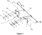
Figure 1 is a three-dimensional structural view of a sand lubrication system according to the present application; -
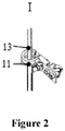
Figure 2 is a partially enlarged schematic view showing the structure ofFigure 1 ; -
Figure 3 is a schematic front view showing the structure of the sand lubrication system mounted on the EMU according to the present application ; -
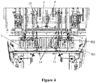
Figure 4 is a schematic bottom view showing the structure ofFigure 3 ; -
Figure 5 is a schematic left view showing the structure ofFigure 3 ; and -
Figure 6 is a structural view of the distributor of the sand lubrication system according to the present application. - In order to provide those skilled in the art a better understanding of the solutions of the present application, the present application is described hereinafter in further detail in conjunction with the drawings and embodiments.
- As shown in
Figures 1 to 6 , the present application discloses a sand lubrication system used for an EMU. Since the braking and lubrication of the EMU are mainly on the head vehicle of the EMU, the sand lubrication system disclosed by the present application is often used on the head vehicle of the EMU, and it should be noted that it may also be mounted on other vehicle bodies that require lubrication and braking. - The sand lubrication system includes a
sand box 1, asand pipe 5, a sand spray nozzle, a lubricant supply device, alubricating pipe 7 and a fuel spray nozzle. - The EMU includes a
chassis 2 and abogie 3, thebogie 3 is rotatably mounted on thechassis 2, and a baffle 4 is arranged between thebogie 3 and the dynamic front end of thechassis 2 to improve the dynamic performance of the EMU and reduce the running resistance of the EMU. Thesand box 1 is arranged between thebogie 3 and the dynamic front end of thechassis 2, and thesand box 1 is integrated with thechassis 2. Specifically, thesand box 1 may be welded with thechassis 2 or integrally formed, which avoids the shaking of the sand box along with the vibration of the EMU, further avoids the shaking of thesand pipe 5, and improves the service life of thesand pipe 5. - One end of the
sand pipe 5 is in communication with the outlet at the bottom of thesand box 1, and another end of thesand pipe 5 is in communication with the sand spray nozzle by passing through the baffle 4, and the sand spray nozzle may spray the materials delivered by thesand pipe 5 to the wheels 6 on thebogie 3. In order to facilitate sand discharge, the present application further discloses that the height of the sand spray pipe is higher than that of the sand spray nozzle. - The lubricant supply device is arranged between the
bogie 3 and the dynamic front end of thechassis 2, and the lubricant supply device is mounted on thechassis 2. Specifically, the lubricant supply device may be any structure capable of supplying lubricant to the fuel spray nozzle. - One end of the
lubricating pipe 7 is in communication with the outlet of the lubricant supply device, and another end of thelubricating pipe 7 is in communication with the fuel spray nozzle by bypassing the baffle 4, and the fuel spray nozzle may spray the lubricant delivered by thelubricating pipe 7 on the rims of the wheels 6. - For the sand lubrication system disclosed by the present application, when the EMU needs braking, the materials in the
sand box 1 are delivered to the sand spray nozzle through thesand pipe 5, and are sprayed to the wheels 6 through the sand spray nozzle to improve the adhesive coefficient between the wheels and rails. When it is necessary to reduce the wear of the rims of the wheels 6, the lubricant is delivered by the lubricant supply device to the fuel spray nozzle through thelubricating pipe 7, and is sprayed to the rims of the wheels 6 through the fuel spray nozzle, which reduces the wear of the rims of the wheels 6, thus reducing the times and maintenance costs for maintaining and grinding the wheel 6, reducing the noise of the EMU in bends and tunnels, and reducing the risk of the wheels 6 going off the rail. - In addition, the
sand box 1 of the present application is integrated with thechassis 2 of the EMU. Therefore, the reliable mounting of the sand lubrication system can be realized even if the baffle 4 is mounted between thebogie 3 and the dynamic front end of thechassis 2 of the EMU, and the space for mounting the sand lubrication system is narrow. - In summary, the wear of the wheels 6 of the EMU and the slipping probability of the EMU during braking are reduced according to the present application.
- In the second embodiment according to the present application, the structure of the sand lubrication system in this embodiment is similar to that in the first embodiment, so the similarities will not be described again, and only the differences will be introduced.
- In this embodiment, the application specifically discloses that the lubricant supply device includes a drive pump, an oil-gas mixing module and a
distributor 8. - The drive pump can pump lubricant into the oil-gas mixing module. The
distributor 8 is mounted on thelubricating pipe 7, and is in communication with the outlet of the oil-gas mixing module through thelubricating pipe 7. The two outlets of thedistributor 8 are respectively in communication with the fuel spray nozzles on both sides through thelubricating pipe 7, so as to spray lubricant on the wheels 6 on both sides of the EMU. - Specifically, the drive pump may be a pneumatic plunger pump. It should be noted that it may also be other types of pumps. In this embodiment, the drive pump is a pneumatic plunger pump as an example. In use, the lubricant is pumped into the oil-gas mixing module by the pneumatic plunger pump, and the lubricant and air are mixed in the oil-gas mixing module. Under the action of compressed air, the lubricant is delivered along the inner wall of the
lubricating pipe 7, distributed by thedistributor 8 and then supplied to the fuel spray nozzle, from which the lubricant is sprayed onto the rims of the wheels 6. - Further, the present application discloses that the
distributor 8 includes avertical distribution valve 801 and ahorizontal distribution valve 802. Thevertical distribution valve 801 and thehorizontal distribution valve 802 are vertically arranged to realize the steering of thelubricating pipe 7. The inlet of thevertical distribution valve 801 is in communication with the oil-gas mixing module through thelubricating pipe 7, the inlet of thehorizontal distribution valve 802 is in communication with the outlet of thevertical distribution valve 801, and the two outlets of thehorizontal distribution valve 802 are in communication with the fuel spray nozzle. - Further, the present application discloses that the
lubricating pipe 7 includes a lubricatinghard pipe 701 and a lubricatingsoft pipe 702. Thedistributor 8 is mounted on the lubricatinghard pipe 701. One end of the lubricatingsoft pipe 702 is in communication with the lubricatinghard pipe 701, and another end of the lubricatingsoft pipe 702 is in communication with the fuel spray nozzle. Specifically, In order to avoid the baffle 4, the lubricatingsoft pipe 702 is arranged in a U shape. - Further, the present application discloses that the
sand pipe 5 includes a sandsoft pipe 501 and a sandhard pipe 502. One end of the sandhard pipe 502 is in communication with thesand box 1, and another end of the sandhard pipe 502 is in communication with the sandsoft pipe 501 through a partition straight joint 14 mounted on the baffle 4. - Further, the present application discloses that the sand lubrication system includes multiple connecting
plates 9. The connectingplates 9 are mounted on thechassis 2, and both thelubricating pipe 7 and thesand pipe 5 are fixed on the connectingplates 9. Each of the connectingplates 9 is specifically a strip-shaped plate, through which both thelubricating pipe 7 and thesand pipe 5 are fixed on thechassis 2, thus realizing the compact connection between thelubricating pipe 7 and thesand pipe 5. - Further, the present application discloses that the sand lubrication system includes
tensioning devices 10 and pipe clamps 11. The pipe clamps 11 are respectively fixed on the sandsoft pipe 501 and the lubricatingsoft pipe 702. Each of thetensioning devices 10 has one end connected with the correspondingpipe clamp 11, and another end connected with thechassis 2. - In order to improve the fatigue resistance of the pipe clamps 11, the present application discloses that each of the pipe clamps 11 is a metal pipe clamp.
- Further, the present application specifically discloses that each of the
tensioning devices 10 includes a lifting socket, a lug, a wire rope and a rope puller. The lifting socket is fixed on thechassis 2. Specifically, the lifting socket is welded on thechassis 2 which improves the mounting strength of the lifting socket and thechassis 2. It should be noted that the lifting socket may be detachably connected to thechassis 2 by screws or the like. - One end of the lug is fixed on the lifting socket, and another end of the lug is connected with the wire rope. One end of the rope puller is connected with the wire rope, and another end of the rope puller is connected with the
metal pipe clamp 11. - Since the sand
soft pipe 501 and the lubricatingsoft pipe 702 are easy to shake with the vibration of the EMU. With the tightening action of the tighteningdevice 10, on the one hand, the sagging of the sandsoft pipe 501 and the lubricatingsoft pipe 702 is avoided, and on another hand, the shaking amplitude of the sandsoft pipe 501 and thelubricating pipe 702 is reduced. - Further, the present application discloses that a lifting socket is provided with multiple lifting rings for fixing lugs, and the multiple lifting rings are uniformly distributed to realize the connection and adjustment of the pipe clamps 11 at different positions.
- Further, the present application discloses that the sand lubrication system includes a sand dry-
air pipe 12. The sand dry-air pipe 12 and thesand pipe 5 are fixed together to realize the drying of the borax in thesand pipe 5. - Further, the present application discloses that the sand lubrication system includes a felt
strip 13. The feltstrip 13 covers the lubricatingsoft pipe 702 to reduce wear on the lubricatingsoft pipe 702. - Further, the felt
strip 13 can also cover the sandsoft pipe 501 to reduce wear on the sandsoft pipe 501. - When the present application is used, a baffle 4 is added between the lower part of the dynamic front end and the
bogie 3 of the EMU. First, thesand pipe 5 is connected to thesand box 1 and is fastened. Then, the baffle 4 is mounted, and then thetensioning device 10 is assembled. Finally, thepipe clamp 11 and a hanger plate are mounted on thetensioning device 10. A suitable distance is chosen to cover the lubricatingsoft pipe 702 with a feltstrip 13 for protection, and then thepipe clamp 11 and the hanger plate are connected to the wire rope of the sandsoft pipe 501 through thetensioning device 10. A suitable distance is further chosen and a set ofsuch tensioning device 10 is added, and thetensioning device 10 is finally connected to the gas path port of the fuel spray nozzle of thebogie 3. If the distance is not suitable, it will be determined after the vehicle completes the small curve test. In this manner, the lubricatingsoft pipe 702 will swing along with thebogie 3 and the sandsoft pipe 501 to avoid interference. Under the condition of limited space, the reasonable arrangement of thesand pipe 5 and thelubricating pipe 7 is realized, and the sand and rim lubrication functions of the head vehicle are realized. - In the present application, the
sand box 1 is directly integrated on the vehicle body and is integrated with the dynamic front end of the vehicle body, and a baffle 4 is added between the dynamic front end and thebogie 3, so that the rim lubrication and thesand pipe 5 respectively go through two pipelines, and a fixed point (the connection point between thetensioning device 10 and the lubricating pipe 7) is added to thelubricating pipe 7. Due to the limited space between thebogie 3 and the baffle 4, the lubricatingsoft pipe 702 is connected in U shape. When thebogie 3 swings within 7 degrees left and right from the longitudinal center of the vehicle body, in order to prevent interference with the lubricatingsoft pipe 702, both the lubricatinghard pipe 701 and the sandhard pipe 502 are connected to thechassis 2 through the connectingplate 9 to make the horizontal straight section of the lubricatinghard pipe 701 as close as possible to the baffle 4. In order to prevent the lubricatingsoft pipe 702 from rubbing against the wire rope directly, the lubricatingsoft pipe 702 is covered with the feltstrip 13 for protection, and two sets of fixing devices are added to connect with the wire rope, thus a consistent swing can be maintained as thebogie 3 swings, thereby effectively avoiding the interference of abrasion and collision. Thesand pipe 5 is connected by the partition straight joint 14 on a vertical partition of the baffle 4, passes between the dynamic front end and the baffle 4, and is fixed by a bracket welded below the dynamic front end. The assembly error is effectively reduced because thesand box 1 and thechassis 2 are integrated. Under the limited space condition between thebogie 3 and the baffle 4 of the head vehicle of the EMU, the reliability of the connection between thelubricating pipe 7 and thebogie 3 is solved, and the reliable work of the sand lubrication system can be ensured when the EMU goes through turnouts and bends. - The present application provides an EMU, including a
chassis 2, abogie 3 and the sand lubrication system according to any one of the above embodiments. - The
bogie 3 may be rotatably mounted on thechassis 2, and a baffle 4 is arranged between thebogie 3 and the dynamic front end of thechassis 2. Multiple guide grooves are opened on the baffle 4 to improve the dynamic performance of the EMU and reduce the running resistance of the EMU - Since the EMU according to the present application includes the sand lubrication system according to any one of the above embodiments, the beneficial effects of the sand lubrication system are all included in the EMU according to the present application.
- In the present application, "first" and "second" are different in description and have no other special meanings.
- In the description of the present application, it is to be understood that the orientation or positional relationships indicated by terms "horizontal", "vertical", "bottom" and the like are based on the orientation or positional relationships shown in the drawings, and are merely for the convenience of describing the present application and the simplification of the description, and do not indicate or imply that the device or element referred to must be in a particular orientation, or be constructed and operated in a particular orientation, and therefore should not be construed as a limit to the scope of the present application.
- The description of the embodiments herein enables the person skilled in the art to implement or use the present application. Various modifications to the embodiments are apparent to the person skilled in the art, and the general principle defined herein can be implemented in other embodiments without departing from the spirit or scope of the present application. Therefore, the present application is not limited to the embodiments described herein, but should be in accordance with the broadest scope consistent with the principle and novel features disclosed herein.
| 1 | | 2 | |
| 3 | bogie | 4 | |
| 5 | sand pipe | 6 | |
| 7 | | 8 | |
| 801 | | 802 | |
| 701 | lubricating | 702 | lubricating |
| 501 | sand | 502 | sand |
| 9 | connecting | 10 | |
| 11 | | 12 | sand dry- |
| 13 | | 14 | partition straight joint |
Claims (10)
- A sand lubrication system, which is used for an electric multiple unit (EMU), comprising:a sand box (1), wherein the EMU comprises a chassis (2) and a bogie (3), and the bogie (3) is rotatably mounted on the chassis (2), a baffle (4) is provided between the bogie (3) and a dynamic front end of the chassis (2), and the sand box (1) is arranged between the bogie (3) and the dynamic front end of the chassis (2), and is integrated with the chassis (2);a sand pipe (5) and a sand spray nozzle, wherein one end of the sand pipe (5) is in communication with an outlet of a bottom end of the sand box (1), and another end of the sand pipe (5) is in communication with the sand spray nozzle by passing through the baffle (4), and the sand spray nozzle is configured to spray materials delivered by the sand pipe (5) to wheels (6) on the bogie;a lubricant supply device, wherein the lubricant supply device is arranged between the bogie (3) and the dynamic front end of the chassis (2), and is mounted on the chassis (2); anda lubricating pipe (7) and a fuel spray nozzle, wherein one end of the lubricating pipe (7) is in communication with an outlet of the lubricant supply device, and another end of the lubricating pipe (7) is in communication with the fuel spray nozzle by bypassing the baffle (4), and the fuel spray nozzle is configured to spray the lubricant delivered by the lubricating pipe (7) to rims of the wheels (6).
- The sand lubrication system according to claim 1, wherein, the lubricant supply device comprises a drive pump, an oil-gas mixing module and a distributor (8);
the drive pump is configured to pump the lubricant into the oil-gas mixing module; and
the distributor (8) is mounted on the lubricating pipe (7) and is in communication with an outlet of the oil-gas mixing module through the lubricating pipe (7), and two outlets of the distributor (8) are respectively in communication with the fuel spray nozzles at two sides through the lubricating pipe (7). - The sand lubrication system according to claim 2, wherein, the distributor (8) comprises a vertical distribution valve (801) and a horizontal distribution valve (802); and
the vertical distribution valve (801) and the horizontal distribution valve (802) are vertically arranged, an inlet of the vertical distribution valve (801) is in communication with the oil-gas mixing module through the lubricating pipe (7), an inlet of the horizontal distribution valve (802) is in communication with an outlet of the vertical distribution valve (801), and two outlets of the horizontal distribution valve (802) are in communication with the fuel spray nozzle. - The sand lubrication system according to claim 2, wherein, the lubricating pipe (7) comprises a lubricating hard pipe (701) and a lubricating soft pipe (702);
the distributor (8) is arranged on the lubricating hard pipe (701), one end of the lubricating soft pipe (702) is in communication with the lubricating hard pipe (701), and another end of the lubricating soft pipe (702) is in communication with the fuel spray nozzle; and/or
the sand pipe (5) comprises a sand soft pipe (501) and a sand hard pipe (502);
one end of the sand hard pipe (502) is in communication with the sand box (1); and
another end of the sand hard pipe (502) is in communication with the sand soft pipe (501) through a partition straight joint (14) mounted on the baffle (4). - The sand lubrication system according to claim 4, wherein, the lubricating soft pipe (702) is arranged in a U shape.
- The sand lubrication system according to any one of claims 1 to 5, further comprising a plurality of connecting plates (9);
wherein the connecting plates (9) are mounted on the chassis (2), and the lubricating pipe (7) and the sand pipe (5) are both fixed on the connecting plates (9). - The sand lubrication system according to claim 4, further comprising tensioning devices (10) and pipe clamps (11);
wherein the pipe clamps (11) are respectively fixed on the sand soft pipe (501) and the lubricating soft pipe (702), and each of the tensioning devices (10) has one end connected with corresponding the pipe clamp (11), and another end connected with the chassis (2). - The sand lubrication system according to claim 7, wherein, each of the tensioning devices (10) comprises a lifting socket, a lug, a wire rope and a rope puller;
the lifting socket is fixed on the chassis (2);
one end of the lug is fixed on the lifting socket, and another end of the lug is connected with the wire rope;
one end of the rope puller is connected with the wire rope, and another end of the rope puller is connected with the corresponding pipe clamp (11); and/or
each of the pipe clamps (11) is an adjustable metal buckle. - The sand lubrication system according to claim 4, further comprising a sand dry-air pipe (12);
the sand dry-air pipe (12) is fixed together with the sand pipe (5); and/or
the sand lubrication system further comprises a felt strip (13); and
the felt strip (13) is configured to cover the lubricating soft pipe (702). - An EMU, comprising a chassis (2), a bogie (3) and the sand lubrication system according to any one of claims 1 to 9; and
wherein the bogie (3) is rotatably mounted on the chassis (2), a baffle (4) is arranged between the bogie (3) and a dynamic front end of the chassis (2), and a plurality of guide grooves are opened on the baffle (4).
Applications Claiming Priority (3)
| Application Number | Priority Date | Filing Date | Title |
|---|---|---|---|
| CN201920243124.0U CN209700688U (en) | 2019-02-26 | 2019-02-26 | A kind of EMU and its stucco lubricating system |
| CN201910141731.0A CN109849962B (en) | 2019-02-26 | 2019-02-26 | Motor train unit and sanding lubrication system thereof |
| PCT/CN2020/072390 WO2020173239A1 (en) | 2019-02-26 | 2020-01-16 | Motor train unit and sanding lubrication system therefor |
Publications (2)
| Publication Number | Publication Date |
|---|---|
| EP3744604A1 true EP3744604A1 (en) | 2020-12-02 |
| EP3744604A4 EP3744604A4 (en) | 2022-02-09 |
Family
ID=72239128
Family Applications (1)
| Application Number | Title | Priority Date | Filing Date |
|---|---|---|---|
| EP20756740.5A Withdrawn EP3744604A4 (en) | 2019-02-26 | 2020-01-16 | Motor train unit and sanding lubrication system therefor |
Country Status (4)
| Country | Link |
|---|---|
| EP (1) | EP3744604A4 (en) |
| MY (1) | MY203656A (en) |
| SG (1) | SG11202007938UA (en) |
| WO (1) | WO2020173239A1 (en) |
Family Cites Families (11)
| Publication number | Priority date | Publication date | Assignee | Title |
|---|---|---|---|---|
| JPS5934550B2 (en) * | 1979-09-12 | 1984-08-23 | 稔 神谷 | Energy-saving running method using adhesive drive |
| US5477941A (en) * | 1994-03-15 | 1995-12-26 | Tranergy Corporation | On-board lubrication system for direct application to curved and tangent railroad track |
| US6893058B2 (en) * | 2002-10-18 | 2005-05-17 | General Electric Company | Railway train friction management and control system and method |
| CN203888791U (en) * | 2014-05-05 | 2014-10-22 | 南车株洲电力机车有限公司 | Railway vehicle, bogie and sand spreading and wheel rim lubricating installing assembly thereof |
| CN203888826U (en) * | 2014-05-27 | 2014-10-22 | 绍兴柯桥江滨水处理有限公司 | Rail lubricator for reciprocating suction dredger |
| CN205890880U (en) * | 2016-08-26 | 2017-01-18 | 成都市新筑路桥机械股份有限公司 | Lubricated integrated system of 100% low -floor train stucco and rim |
| CN106882198A (en) * | 2017-03-22 | 2017-06-23 | 中车太原机车车辆有限公司 | A kind of engineering truck hydraulic-driven meter gauge bogie |
| CN107415964B (en) * | 2017-05-18 | 2024-01-30 | 中车青岛四方机车车辆股份有限公司 | Installation device of rail vehicle sanding barrier |
| CN108189856A (en) * | 2018-01-22 | 2018-06-22 | 中车长春轨道客车股份有限公司 | Quick big axis heavy load car power truck |
| CN109849962B (en) * | 2019-02-26 | 2024-07-30 | 中车长春轨道客车股份有限公司 | Motor train unit and sanding lubrication system thereof |
| CN209700688U (en) * | 2019-02-26 | 2019-11-29 | 中车长春轨道客车股份有限公司 | A kind of EMU and its stucco lubricating system |
-
2020
- 2020-01-16 WO PCT/CN2020/072390 patent/WO2020173239A1/en not_active Ceased
- 2020-01-16 MY MYUI2020004217A patent/MY203656A/en unknown
- 2020-01-16 SG SG11202007938UA patent/SG11202007938UA/en unknown
- 2020-01-16 EP EP20756740.5A patent/EP3744604A4/en not_active Withdrawn
Also Published As
| Publication number | Publication date |
|---|---|
| SG11202007938UA (en) | 2020-10-29 |
| EP3744604A4 (en) | 2022-02-09 |
| MY203656A (en) | 2024-07-11 |
| WO2020173239A1 (en) | 2020-09-03 |
Similar Documents
| Publication | Publication Date | Title |
|---|---|---|
| CN109849962B (en) | Motor train unit and sanding lubrication system thereof | |
| CA2748953A1 (en) | Sand spreading system | |
| CN104554307A (en) | Motor train unit body and inner windshield mounting structure thereof | |
| CN105109501B (en) | A kind of accessory mounting device used for rail vehicle and its installation method | |
| CN209700688U (en) | A kind of EMU and its stucco lubricating system | |
| CN207173603U (en) | A kind of rail vehicle truck and its stucco and wheel spray common support device | |
| CN203032694U (en) | Conveying device for shot blasting and machining for railway truck bodies | |
| CN109625004B (en) | Sand spreading device, intermediate car and motor train unit | |
| WO2020173239A1 (en) | Motor train unit and sanding lubrication system therefor | |
| CN210793197U (en) | railway tractor | |
| CN107054099B (en) | Three-rail current-receiving transition device and vehicle with same | |
| CN204915690U (en) | Accessory installation device for rail vehicle | |
| CN216943095U (en) | Rim lubricating device and rail vehicle | |
| CN210912183U (en) | Aviation clear water supply vehicle-mounted water tank | |
| CN204984555U (en) | Heavy truck's urea tank support | |
| CN212820598U (en) | Make things convenient for frame-type spraying device for container of multi-angle regulation | |
| CN208196464U (en) | A kind of flow-guiding board of vehicle grinding device of multi-directionally operation | |
| CN222331320U (en) | Frame for integrally hoisting auxiliary air compressor of high-speed motor train unit and high-speed motor train unit | |
| CN209667087U (en) | Mounting structure of rail vehicle and its roof hinged seat | |
| CN205086935U (en) | Air suspension device | |
| CN209519954U (en) | An auxiliary device for spraying train wheels | |
| CN111576314A (en) | Dust collecting equipment is used in road engineering construction | |
| CN105665189A (en) | Glue spraying equipment of large spraying system | |
| CN120886877A (en) | Methods for transporting bogies and cross-gauge locomotives of broad gauge locomotives | |
| CN205381144U (en) | Mining tractor |
Legal Events
| Date | Code | Title | Description |
|---|---|---|---|
| STAA | Information on the status of an ep patent application or granted ep patent |
Free format text: STATUS: UNKNOWN |
|
| STAA | Information on the status of an ep patent application or granted ep patent |
Free format text: STATUS: THE INTERNATIONAL PUBLICATION HAS BEEN MADE |
|
| PUAI | Public reference made under article 153(3) epc to a published international application that has entered the european phase |
Free format text: ORIGINAL CODE: 0009012 |
|
| STAA | Information on the status of an ep patent application or granted ep patent |
Free format text: STATUS: REQUEST FOR EXAMINATION WAS MADE |
|
| 17P | Request for examination filed |
Effective date: 20200824 |
|
| AK | Designated contracting states |
Kind code of ref document: A1 Designated state(s): AL AT BE BG CH CY CZ DE DK EE ES FI FR GB GR HR HU IE IS IT LI LT LU LV MC MK MT NL NO PL PT RO RS SE SI SK SM TR |
|
| AX | Request for extension of the european patent |
Extension state: BA ME |
|
| A4 | Supplementary search report drawn up and despatched |
Effective date: 20220110 |
|
| RIC1 | Information provided on ipc code assigned before grant |
Ipc: B61K 3/02 20060101ALI20220103BHEP Ipc: B61C 15/10 20060101AFI20220103BHEP |
|
| DAV | Request for validation of the european patent (deleted) | ||
| DAX | Request for extension of the european patent (deleted) | ||
| STAA | Information on the status of an ep patent application or granted ep patent |
Free format text: STATUS: THE APPLICATION IS DEEMED TO BE WITHDRAWN |
|
| 18D | Application deemed to be withdrawn |
Effective date: 20220809 |