EP3744567A1 - A vehicule for transporting a wind turbine blade - Google Patents
A vehicule for transporting a wind turbine blade Download PDFInfo
- Publication number
- EP3744567A1 EP3744567A1 EP19380010.9A EP19380010A EP3744567A1 EP 3744567 A1 EP3744567 A1 EP 3744567A1 EP 19380010 A EP19380010 A EP 19380010A EP 3744567 A1 EP3744567 A1 EP 3744567A1
- Authority
- EP
- European Patent Office
- Prior art keywords
- vehicle
- semi
- rotatory table
- steering
- blade
- Prior art date
- Legal status (The legal status is an assumption and is not a legal conclusion. Google has not performed a legal analysis and makes no representation as to the accuracy of the status listed.)
- Granted
Links
Images




Classifications
-
- B—PERFORMING OPERATIONS; TRANSPORTING
- B60—VEHICLES IN GENERAL
- B60P—VEHICLES ADAPTED FOR LOAD TRANSPORTATION OR TO TRANSPORT, TO CARRY, OR TO COMPRISE SPECIAL LOADS OR OBJECTS
- B60P3/00—Vehicles adapted to transport, to carry or to comprise special loads or objects
- B60P3/40—Vehicles adapted to transport, to carry or to comprise special loads or objects for carrying long loads, e.g. with separate wheeled load supporting elements
-
- F—MECHANICAL ENGINEERING; LIGHTING; HEATING; WEAPONS; BLASTING
- F03—MACHINES OR ENGINES FOR LIQUIDS; WIND, SPRING, OR WEIGHT MOTORS; PRODUCING MECHANICAL POWER OR A REACTIVE PROPULSIVE THRUST, NOT OTHERWISE PROVIDED FOR
- F03D—WIND MOTORS
- F03D13/00—Assembly, mounting or commissioning of wind motors; Arrangements specially adapted for transporting wind motor components
- F03D13/40—Arrangements or methods specially adapted for transporting wind motor components
-
- Y—GENERAL TAGGING OF NEW TECHNOLOGICAL DEVELOPMENTS; GENERAL TAGGING OF CROSS-SECTIONAL TECHNOLOGIES SPANNING OVER SEVERAL SECTIONS OF THE IPC; TECHNICAL SUBJECTS COVERED BY FORMER USPC CROSS-REFERENCE ART COLLECTIONS [XRACs] AND DIGESTS
- Y02—TECHNOLOGIES OR APPLICATIONS FOR MITIGATION OR ADAPTATION AGAINST CLIMATE CHANGE
- Y02E—REDUCTION OF GREENHOUSE GAS [GHG] EMISSIONS, RELATED TO ENERGY GENERATION, TRANSMISSION OR DISTRIBUTION
- Y02E10/00—Energy generation through renewable energy sources
- Y02E10/70—Wind energy
- Y02E10/72—Wind turbines with rotation axis in wind direction
Definitions
- the present invention is included in the technical field of vehicles for transportation of wind turbine blades. It relates in particular to a vehicle for the transportation of a blade for a wind turbine which incorporate traction, steering and suspension systems, capable of lifting the tip of the blade and tilting it for passing over obstacles encountered during transportation, and further capable of varying the overhang thereof according to national restrictions.
- Document EP 1 644 271 B1 discloses a system to stretch a curved blade by different means during transportation.
- Document EP 1 659 026 B1 describes a system to pivot a blade from a horizontal position to an inclined position during transportation and to change the distance between ends of supporting means of the blade when the blade is pivoted.
- Document EP 1 465 789 B1 and US2006/0285937 discloses a system to rotate a blade 90° about its own axis prior to transporting the blade under a bridge. Thereby, collision between the bridge and the blade can be prevented at the expense that horizontal dimension of the transport increases during transportation under the bridge.
- a vehicle for transporting a wind turbine blade is disclosed herein with which it has been found that at least the above disadvantages relating to the prior art solutions are mitigated.
- a vehicle intended to be towed by a truck for transporting a wind turbine blade comprising a rear portion and a front portion, the front portion configured to be firmly attached to a front rotatory table able to rotate freely on longitudinal axis and vertical axis thereof and operatively mounted on the truck and the rear portion configured to be firmly attached to a rear rotatory table operatively mounted on the vehicle, wherein the vehicle further comprises:
- the vehicle further comprises a sliding system comprising a structure intended to be securely attached to the rear portion of the blade and sliding guides configured to slide through the rear rotatory table allowing to vary overhang of the blade.
- a sliding system comprising a structure intended to be securely attached to the rear portion of the blade and sliding guides configured to slide through the rear rotatory table allowing to vary overhang of the blade.
- the sliding guide may have a number of holes machined to lock the rear rotatory table according to the required overhang.
- the adjustment of the overhang should be done with the lifting system folded or "not lifted", in order to have access to the sliding the guide and the rear rotatory table locks.
- the steering system may comprise steering rods, a system of levers and actuators able to provide movement to the steering system up to substantially 60° in relation to the truck.
- the steering system may comprise an actuator mounted directly on each semi-axle able to provide movement ⁇ 90° (180°) in relation to the truck. I.e. 90° in one direction and 90° in the other direction, achieving a total breadth of 180°.
- the vehicle may have a manual steering system, which activates and deactivates the automatic steering mode, allowing ⁇ 90° (180°) steering angles, depending on steering system selection.
- the vehicle When the steering is on automatic mode, the vehicle follows the path of the truck by means of the rear rotatory table configured to transmit steering to the semi-axles proportionally to the front rotatory table rotation.
- the traction system comprises a variable flow hydraulic pump in the centre of at least one semi-axle for transmitting the movement to the wheels. More preferably, each semi-axle comprises a traction system comprising a variable flow hydraulic pump.
- the hydraulic pump may be electronically controlled by the control system to modify the rotation speed at will and configured to automatically disconnect at a certain speed of the vehicle, in such a way that the semi-axles are dragged by the truck with minimum friction.
- the vehicle is therefore capable of trajectories at an angle of 90° relative to the truck's trajectory, supported by a powerful traction system capable of manoeuvrability with the blade elevated to a certain height to avoid obstacles near the truck.
- control system which comprises a triple system comprising a manual, an electric and a radio frequency system which take the necessary energy from the power system of the vehicle.
- the suspension comprises actuators on the semi-axles, a hydraulic system and solenoid valves.
- the suspension system may comprise a first suspension actuator in an upper part of each semi-axle fixed to the main frame and a second movable actuator fixed to the wheel by an arm and an oscillating axle.
- the actuator of the rear rotatory table is a hydraulic actuator able to transmit steering to the semi-axles proportionally to the front rotatory table rotation to allow the vehicle to follow the same path as the towing truck.
- Said rear rotatory table may further comprise rotation sensors intended to limit the maximum rotation when the rear rotatory table is lifted or "unfolded".
- each semi-axle may be connected by hoses to other actuators, which depending on the load of the blade and the type of transport can form a suspension in triangular or rectangle mode intended for balancing the load and distributing the weight among all the semi-axles, giving great stability to the transport.
- actuators Preferably, by joining actuators with each other in a closed circuit, the fluid leaving one must enter another, which greatly facilitates being able to circulate in any type of road with minimal variations in the levelling of the load.
- the lifting system comprises a platform, a base and a cross profile structure intended to fold and unfold maintaining the lifting platform parallel to the base.
- the main frame is formed by an electrowelded and mechanized metal structure of adequate strength, in which the axles are housed with their suspension and traction system, in addition to the steering system.
- the power system and the control centre are housed in an adjoining cabin, which includes all the installations, commands and safety elements necessary for the work of the vehicle within the strictest safety margins.
- the power system comprises a combustion engine capable of generating enough energy to run the hydraulic traction system and at the same time provide enough energy to charge batteries for the operation of solenoid valves, sensors and other devices previously mentioned.
- control system comprises an electronic panel connected thereof for controlling any one of the steering systems, the lifting system or the traction system. More preferable, capable of controlling all described systems.
- control system comprises a radio control system comprising strategically placed transmitters and receivers for controlling any one of the steering systems, the lifting system or the traction system. More preferable, capable of controlling all described systems.
- Figure 1 illustrates a vehicle (1) intended to be towed by a truck (2) for transporting a wind turbine blade (34) comprising a rear portion (4) and a front portion (3), the front portion (3) configured to be firmly attached to a front rotatory table (6) able to rotate freely on the longitudinal axis and the vertical axis thereof and operatively mounted on the truck (2) and the rear portion (4) of the blade configured to be firmly attached to a rear rotatory table (5) operatively mounted on the vehicle (1).
- FIG. 2 illustrates an upper view of the vehicle (1), comprising an electro welded and mechanized metal mainframe (15).
- Each semi-axle (8) in a preferred embodiment is independent, more in particular in said embodiment, the vehicle (1) comprises ten semi-axles (8), with five on each side, in which the semi-axles (8) are each housed with a suspension system (9).
- Each semi-axle (8) can be connected to the steering system (10) in a preferred embodiment or alternatively some of them can be fixed.
- each semi-axle (8) are provided with traction systems (11) in a preferred embodiment, or alternatively at least some of the semi-axle (8) are provided with traction (11) thereof.
- FIG. 3 illustrates a lifting system (7) comprising a hydraulic actuator (not shown) intended to lift the rear rotatory table (5) with the rear portion (4) of the blade securely mounted thereof.
- the lifting system further comprises a platform (71), a base (72) and a cross profile structure (73) intended to fold and unfold maintaining the lifting platform (71) parallel to the base as shown in Figure 3 .
- Figure 4 illustrates the rear rotatory table (5) in a preferred embodiment, wherein the horizontal and vertical angles of rotation are illustrated, approximately 45° and 10° respectively.
- Figure 4a illustrates the rear rotatory table (5) comprising a tilt system (51) for enabling vertical rotation configured to tilt the blade on longitudinal axis thereof.
- Figure 5 illustrates the front rotatory table (6) in a preferred embodiment, wherein the horizontal and vertical angles of rotation are illustrated, approximately 45° and 10° respectively.
- Figure 5a shows the front rotatory table (6) comprising a tilt system (61) for enabling vertical rotation configured to tilt the blade (34) on longitudinal axis thereof.
- Figure 5b shows an embodiment of the horizontal angle of rotation of the front rotatory table (6).
- Figure 5b shows an embodiment of the horizontal angles of rotation of the rear rotatory table (5).
- the displacement actuators are provided in the rear rotatory table (5), which at rotating, transmit the steering to the semi-axles (8).
- the vehicle is configured so that when the rear table (5) turns to one side by the action of the load, the displacement of actuators causes the vehicle to turn to that same side, providing the proper rotation to the semi-axles (8) so that the vehicle (1) turns at the proper angle for the dolly to pass where the truck (2) has passed.
- the load must be firmly attached to the front rotary table (6) and to the vehicle rear rotary table (5), so that when the truck takes a curve or a slope, the load turns freely and takes the angle corresponding to the layout and the slope of the route where the convoy is driving.
- the front rotatory table (6) must absorb this rotation.
- the vehicle (1) comprises a control system (not shown) comprising an electronic panel connected thereof for controlling any one of the steering systems (10), the lifting system and the traction system (11).
- the control system (not shown) further comprises a remote radio control system comprising strategically placed transmitters and receivers for controlling the steering system (10), the lifting system (7) and the traction system (11).
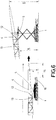
- Figure 6 illustrates the vehicle (1) incorporating a sliding system (12) comprising a structure (13) intended to be securely attached to the rear portion (4) of the blade (34) and sliding guides (121) configured to slide through the rear rotatory table (5) allowing to vary overhang (14) of the blade (34).
- a sliding system (12) comprising a structure (13) intended to be securely attached to the rear portion (4) of the blade (34) and sliding guides (121) configured to slide through the rear rotatory table (5) allowing to vary overhang (14) of the blade (34).
- Figure 7 illustrates how the overhang of the blade can be reduced or increased at will, thus meeting the local traffic restrictions. Where a change of the overhang is needed to overcome the obstacles in the route, it is required that the rear potion of the blade (34) is anchored to the structure (13) with a length equal to or greater than the variation of the required overhang (14).
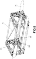
- FIG 8 illustrates the structure (13) of the sliding system (12) wherein the sliding guides (121) are shown in detail.
- Said sliding guides (121) have a number of holes (122) machined to lock the rear rotatory table (5) according to the required overhang (14).
- the adjustment of the overhang (14) should be done with the lifting system (7) folded or "not lifted", in order to have access to the sliding the guide and the rear rotatory table (5) locks.
- Figure 8 clearly shows a mechanism (123) according to a preferred embodiment, configured to firmly attached the blade to the structure (13) and hence to the rear rotatory table (5).
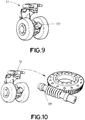
- Figure 9 illustrates the traction system (11) comprising a variable flow hydraulic pump (111) in the centre of the two semi-axles (8) for transmitting the movement to the wheels.
- said hydraulic pump (111) is electronically controlled by the control system to be able to modify the rotation speed at will and configured to automatically disconnect at a certain speed, in such a way that the semi-axles (8) are dragged by the truck (2) with minimum friction.
- FIG. 10 illustrates the steering system (10) for a preferred embodiment described above. More in particular, Fig.10 shows a steering system (10) comprising an actuator (101) directly mounted in each semi-axle (8) intended for providing movement ⁇ 90° (180°) in relation to the truck (2). I.e. 90° in one direction and 90° in the other direction, achieving a total breadth of 180°.
- the suspension system (9) is a direct thrust steering, so the system operates by means of software that commands the actuators (101) and can make the semi-axes (8) rotate in any direction according to the established programming.
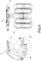
- FIG 11 illustrates an exemplary suspension system (9), in the preferred embodiment being described.
- the suspension system (9) comprises comprises actuators (91) on the semi-axles (8), a hydraulic system (92) and solenoid valves (93).
- the actuators (91) comprising a first suspension actuator (94) in an upper part of each semi-axle (8) fixed to the main frame (15) and a second actuator (95) fixed to the wheel by an arm (96) and an oscillating axle (97) as shown in Figure 8 .
- the vehicle (1) further comprises a power system (16) and batteries (not shown), wherein the power system (16) consists of a combustion engine capable of generating enough energy to run the hydraulic system and at the same time provide enough energy to charge the batteries for the operation of all systems and devices above described.
- the power system (16) consists of a combustion engine capable of generating enough energy to run the hydraulic system and at the same time provide enough energy to charge the batteries for the operation of all systems and devices above described.
- Figure 12 illustrates some of the possibilities of manoeuvrability for the vehicle to pass over possible obstacles. It clearly shows how the vehicle (1) can adjust elevation at the rear portion (4) of the blade (34), change direction with manual steering at up to 90° angles with respect to the truck (2), adjust overhang (14) to required national restrictions and to provide traction for difficult terrain and slopes, being able to successfully transport new generation longer and heavier blades (34) to remote wind farms.
Landscapes
- Engineering & Computer Science (AREA)
- Mechanical Engineering (AREA)
- Sustainable Energy (AREA)
- Life Sciences & Earth Sciences (AREA)
- Chemical & Material Sciences (AREA)
- Combustion & Propulsion (AREA)
- Sustainable Development (AREA)
- General Engineering & Computer Science (AREA)
- Health & Medical Sciences (AREA)
- Public Health (AREA)
- Transportation (AREA)
- Vehicle Body Suspensions (AREA)
- Wind Motors (AREA)
Abstract
Description
- The present invention is included in the technical field of vehicles for transportation of wind turbine blades. It relates in particular to a vehicle for the transportation of a blade for a wind turbine which incorporate traction, steering and suspension systems, capable of lifting the tip of the blade and tilting it for passing over obstacles encountered during transportation, and further capable of varying the overhang thereof according to national restrictions.
- The new generations of wind turbine blades are extremely difficult to transport because of the lengths of over 70 m long and heavier weights. Due to that it is very difficult, and sometimes impossible, to access to harbours, to cross towns and cities, to take intersections, to take curves and to eventually reach remote wind farms.
- Some vehicles are known in the state of art for transporting blades for a wind turbine. However, said vehicles that in the beginning were able to transport longer blades are becoming obsolete and do not have the manoeuvrability required for new dimensions of new generation blades.
-
Document EP 1 644 271 B1 discloses a system to stretch a curved blade by different means during transportation. -
Document EP 1 659 026 B1 describes a system to pivot a blade from a horizontal position to an inclined position during transportation and to change the distance between ends of supporting means of the blade when the blade is pivoted. -
Document EP 1 465 789 B1 andUS2006/0285937 discloses a system to rotate a blade 90° about its own axis prior to transporting the blade under a bridge. Thereby, collision between the bridge and the blade can be prevented at the expense that horizontal dimension of the transport increases during transportation under the bridge. - Nonetheless, the documents mentioned encounter multiple problems for transporting new generation longer and heavier blades. These vehicles may not have the manoeuvrability required in terms of traction, steering, required overhang by national standards, capacity to pass over different obstacles along the roads, technical features which are necessary and essential to work simultaneously on the same vehicle for proper transportation of blades nowadays.
- A vehicle for transporting a wind turbine blade is disclosed herein with which it has been found that at least the above disadvantages relating to the prior art solutions are mitigated.
- More in particular, according to a first aspect of the invention, there is provided a vehicle intended to be towed by a truck for transporting a wind turbine blade comprising a rear portion and a front portion, the front portion configured to be firmly attached to a front rotatory table able to rotate freely on longitudinal axis and vertical axis thereof and operatively mounted on the truck and the rear portion configured to be firmly attached to a rear rotatory table operatively mounted on the vehicle, wherein the vehicle further comprises:
- a main frame comprising at least two semi-axles, each semi-axle comprising at least two wheels, a suspension system, a steering system and a traction system,
- a lifting system comprising a lift actuator intended to lift the rear rotatory table with the rear part of the blade securely mounted thereof, wherein said rear rotatory table comprises an actuator able to transmit steering to the semi-axles proportionally to the front rotatory table rotation and further comprising a tilting system configured to tilt the blade on longitudinal axis thereof,
- a power system and a control system able to manually and remotely control at least any one of: the steering systems, the traction system, the lifting system or the suspension system.
- Preferably, the vehicle further comprises a sliding system comprising a structure intended to be securely attached to the rear portion of the blade and sliding guides configured to slide through the rear rotatory table allowing to vary overhang of the blade.
- Note that the overhang of the load can be reduced or increased at will, thus meeting the local traffic restrictions.
- Where a change of the overhang is needed to overcome the obstacles in the route, that the rear part of the blade should be anchored to the structure with a length equal to or greater than the variation of the required overhang.
- The sliding guide may have a number of holes machined to lock the rear rotatory table according to the required overhang. The adjustment of the overhang should be done with the lifting system folded or "not lifted", in order to have access to the sliding the guide and the rear rotatory table locks.
- In some embodiments, the steering system may comprise steering rods, a system of levers and actuators able to provide movement to the steering system up to substantially 60° in relation to the truck.
- The steering system may comprise an actuator mounted directly on each semi-axle able to provide movement ± 90° (180°) in relation to the truck. I.e. 90° in one direction and 90° in the other direction, achieving a total breadth of 180°.
- Note that for those cases where great manoeuvrability is required, the vehicle may have a manual steering system, which activates and deactivates the automatic steering mode, allowing ± 90° (180°) steering angles, depending on steering system selection.
- When the steering is on automatic mode, the vehicle follows the path of the truck by means of the rear rotatory table configured to transmit steering to the semi-axles proportionally to the front rotatory table rotation.
- Preferably, the traction system comprises a variable flow hydraulic pump in the centre of at least one semi-axle for transmitting the movement to the wheels. More preferably, each semi-axle comprises a traction system comprising a variable flow hydraulic pump.
- The hydraulic pump may be electronically controlled by the control system to modify the rotation speed at will and configured to automatically disconnect at a certain speed of the vehicle, in such a way that the semi-axles are dragged by the truck with minimum friction.
- The vehicle is therefore capable of trajectories at an angle of 90° relative to the truck's trajectory, supported by a powerful traction system capable of manoeuvrability with the blade elevated to a certain height to avoid obstacles near the truck.
- Preferably, all systems mentioned, in addition to the suspension, lights, brakes, can be controlled at will by the control system which comprises a triple system comprising a manual, an electric and a radio frequency system which take the necessary energy from the power system of the vehicle.
- Preferably, the suspension comprises actuators on the semi-axles, a hydraulic system and solenoid valves.
- The suspension system may comprise a first suspension actuator in an upper part of each semi-axle fixed to the main frame and a second movable actuator fixed to the wheel by an arm and an oscillating axle.
- Preferably, the actuator of the rear rotatory table is a hydraulic actuator able to transmit steering to the semi-axles proportionally to the front rotatory table rotation to allow the vehicle to follow the same path as the towing truck. Said rear rotatory table may further comprise rotation sensors intended to limit the maximum rotation when the rear rotatory table is lifted or "unfolded".
- The actuators of each semi-axle may be connected by hoses to other actuators, which depending on the load of the blade and the type of transport can form a suspension in triangular or rectangle mode intended for balancing the load and distributing the weight among all the semi-axles, giving great stability to the transport. Preferably, by joining actuators with each other in a closed circuit, the fluid leaving one must enter another, which greatly facilitates being able to circulate in any type of road with minimal variations in the levelling of the load.
- Preferably, the lifting system comprises a platform, a base and a cross profile structure intended to fold and unfold maintaining the lifting platform parallel to the base.
- Preferably, the main frame is formed by an electrowelded and mechanized metal structure of adequate strength, in which the axles are housed with their suspension and traction system, in addition to the steering system.
- Preferably, the power system and the control centre are housed in an adjoining cabin, which includes all the installations, commands and safety elements necessary for the work of the vehicle within the strictest safety margins.
- Preferably, the power system comprises a combustion engine capable of generating enough energy to run the hydraulic traction system and at the same time provide enough energy to charge batteries for the operation of solenoid valves, sensors and other devices previously mentioned.
- Preferably, the control system comprises an electronic panel connected thereof for controlling any one of the steering systems, the lifting system or the traction system. More preferable, capable of controlling all described systems.
- Preferably, the control system comprises a radio control system comprising strategically placed transmitters and receivers for controlling any one of the steering systems, the lifting system or the traction system. More preferable, capable of controlling all described systems.
- To complement the description being made and in order to aid towards a better understanding of the characteristics of the invention, in accordance with a preferred example of practical embodiment thereof, a set of drawings is attached as an integral part of said description wherein, with illustrative and non-limiting character, the following has been represented:
-
Figure 1 .- illustrates the blade firmly attached to the front rotatory table operatively attached to the truck and to the rear rotatory table operatively attached on the vehicle. -
Figure 2 .- illustrates an upper view of the vehicle for transporting blades, clearly showing the semi-axles and the rear rotatory table. -
Figure 3 .- illustrates the lifting system "folded" and "unfolded" and the rear rotatory table. -
Figure 4 .- Illustrates the rear rotatory table in a preferred embodiment, whereinfigure 4a shows the vertical angle of rotation of the rear rotatory table and 5b shows the horizontal angle of rotation of the rear rotatory table. -
Figure 5 .- Illustrates the front rotatory table in a preferred embodiment, whereinfigure 5a shows the vertical angle of rotation of the front rotatory table and 5b the horizontal angle of rotation of the front rotatory table. -
Figure 6 .- Illustrates the sliding system, where it can be clearly seen the structure configured to slide on the rear rotatory table and securely attached to the rear part of the blade. -
Figure 7 .- Illustrates the sliding system configured to vary the required overhang at will. -
Figure 8 .- lillustrates a view in perspective of the structure of the sliding system wherein the sliding guides and attach mechanism are showed in detail. -
Figure 9 .- Illustrates the traction system comprising a hydraulic pump. -
Figure 10 .- Illustrates the steering system comprising an actuator directly mounted on the semi-axle according to a preferred embodiment of the invention. -
Figure 11 .- Illustrates the suspension system according to a preferred embodiment of the invention. -
Figure 12 .- illustrates some of the possibilities of manoeuvrability for the vehicle to pass over possible obstacles - A detailed explanation of an example of preferred embodiment of the object of the present invention is provided below, with the aid of the aforementioned figures.
-
Figure 1 illustrates a vehicle (1) intended to be towed by a truck (2) for transporting a wind turbine blade (34) comprising a rear portion (4) and a front portion (3), the front portion (3) configured to be firmly attached to a front rotatory table (6) able to rotate freely on the longitudinal axis and the vertical axis thereof and operatively mounted on the truck (2) and the rear portion (4) of the blade configured to be firmly attached to a rear rotatory table (5) operatively mounted on the vehicle (1). -
Figure 2 illustrates an upper view of the vehicle (1), comprising an electro welded and mechanized metal mainframe (15). Each semi-axle (8) in a preferred embodiment is independent, more in particular in said embodiment, the vehicle (1) comprises ten semi-axles (8), with five on each side, in which the semi-axles (8) are each housed with a suspension system (9). Each semi-axle (8) can be connected to the steering system (10) in a preferred embodiment or alternatively some of them can be fixed. Alike, each semi-axle (8) are provided with traction systems (11) in a preferred embodiment, or alternatively at least some of the semi-axle (8) are provided with traction (11) thereof. -
Figure 3 illustrates a lifting system (7) comprising a hydraulic actuator (not shown) intended to lift the rear rotatory table (5) with the rear portion (4) of the blade securely mounted thereof. - The lifting system further comprises a platform (71), a base (72) and a cross profile structure (73) intended to fold and unfold maintaining the lifting platform (71) parallel to the base as shown in
Figure 3 . -
Figure 4 illustrates the rear rotatory table (5) in a preferred embodiment, wherein the horizontal and vertical angles of rotation are illustrated, approximately 45° and 10° respectively.Figure 4a illustrates the rear rotatory table (5) comprising a tilt system (51) for enabling vertical rotation configured to tilt the blade on longitudinal axis thereof. -
Figure 5 illustrates the front rotatory table (6) in a preferred embodiment, wherein the horizontal and vertical angles of rotation are illustrated, approximately 45° and 10° respectively.Figure 5a shows the front rotatory table (6) comprising a tilt system (61) for enabling vertical rotation configured to tilt the blade (34) on longitudinal axis thereof.Figure 5b shows an embodiment of the horizontal angle of rotation of the front rotatory table (6). -
Figure 5b shows an embodiment of the horizontal angles of rotation of the rear rotatory table (5). The displacement actuators are provided in the rear rotatory table (5), which at rotating, transmit the steering to the semi-axles (8). - The vehicle is configured so that when the rear table (5) turns to one side by the action of the load, the displacement of actuators causes the vehicle to turn to that same side, providing the proper rotation to the semi-axles (8) so that the vehicle (1) turns at the proper angle for the dolly to pass where the truck (2) has passed.
- The load must be firmly attached to the front rotary table (6) and to the vehicle rear rotary table (5), so that when the truck takes a curve or a slope, the load turns freely and takes the angle corresponding to the layout and the slope of the route where the convoy is driving. In addition, when the load is lifted at the rear by the lift, the front rotatory table (6) must absorb this rotation.
- The vehicle (1) comprises a control system (not shown) comprising an electronic panel connected thereof for controlling any one of the steering systems (10), the lifting system and the traction system (11). The control system (not shown) further comprises a remote radio control system comprising strategically placed transmitters and receivers for controlling the steering system (10), the lifting system (7) and the traction system (11).
-
Figure 6 illustrates the vehicle (1) incorporating a sliding system (12) comprising a structure (13) intended to be securely attached to the rear portion (4) of the blade (34) and sliding guides (121) configured to slide through the rear rotatory table (5) allowing to vary overhang (14) of the blade (34). -
Figure 7 illustrates how the overhang of the blade can be reduced or increased at will, thus meeting the local traffic restrictions. Where a change of the overhang is needed to overcome the obstacles in the route, it is required that the rear potion of the blade (34) is anchored to the structure (13) with a length equal to or greater than the variation of the required overhang (14). -
Figure 8 illustrates the structure (13) of the sliding system (12) wherein the sliding guides (121) are shown in detail. Said sliding guides (121) have a number of holes (122) machined to lock the rear rotatory table (5) according to the required overhang (14). The adjustment of the overhang (14) should be done with the lifting system (7) folded or "not lifted", in order to have access to the sliding the guide and the rear rotatory table (5) locks. - Furthermore,
Figure 8 clearly shows a mechanism (123) according to a preferred embodiment, configured to firmly attached the blade to the structure (13) and hence to the rear rotatory table (5). -
Figure 9 illustrates the traction system (11) comprising a variable flow hydraulic pump (111) in the centre of the two semi-axles (8) for transmitting the movement to the wheels. Wherein said hydraulic pump (111) is electronically controlled by the control system to be able to modify the rotation speed at will and configured to automatically disconnect at a certain speed, in such a way that the semi-axles (8) are dragged by the truck (2) with minimum friction. -
Figure 10 illustrates the steering system (10) for a preferred embodiment described above. More in particular,Fig.10 shows a steering system (10) comprising an actuator (101) directly mounted in each semi-axle (8) intended for providing movement ± 90° (180°) in relation to the truck (2). I.e. 90° in one direction and 90° in the other direction, achieving a total breadth of 180°. - In the preferred embodiment above mentioned, the suspension system (9) is a direct thrust steering, so the system operates by means of software that commands the actuators (101) and can make the semi-axes (8) rotate in any direction according to the established programming.
-
Figure 11 illustrates an exemplary suspension system (9), in the preferred embodiment being described. The suspension system (9) comprises comprises actuators (91) on the semi-axles (8), a hydraulic system (92) and solenoid valves (93). The actuators (91) comprising a first suspension actuator (94) in an upper part of each semi-axle (8) fixed to the main frame (15) and a second actuator (95) fixed to the wheel by an arm (96) and an oscillating axle (97) as shown inFigure 8 . - The vehicle (1) further comprises a power system (16) and batteries (not shown), wherein the power system (16) consists of a combustion engine capable of generating enough energy to run the hydraulic system and at the same time provide enough energy to charge the batteries for the operation of all systems and devices above described.
-
Figure 12 illustrates some of the possibilities of manoeuvrability for the vehicle to pass over possible obstacles. It clearly shows how the vehicle (1) can adjust elevation at the rear portion (4) of the blade (34), change direction with manual steering at up to 90° angles with respect to the truck (2), adjust overhang (14) to required national restrictions and to provide traction for difficult terrain and slopes, being able to successfully transport new generation longer and heavier blades (34) to remote wind farms.
Claims (14)
- A vehicle (1) intended to be towed by a truck (2) for transporting a wind turbine blade (34) comprising a rear portion (4) and a front portion (3), the front portion (3) configured to be firmly attached to a front rotatory table (6) able to rotate freely on longitudinal axis and vertical axis thereof and operatively mounted on the truck (2) and the rear portion (4) configured to be firmly attached to a rear rotatory table (5) operatively mounted on the vehicle (1), characterized in that the vehicle (1) further comprises:- a main frame (15) comprising at least two semi-axles (8), each semi-axle (8) comprising at least two wheels, a suspension system (9), a steering system (10) and a traction system (11),- a lifting system comprising (7) a lift actuator intended to lift the rear rotatory table (5) with the rear portion (4) of the blade (34) securely mounted thereof, wherein said rear rotatory table (5) comprises an actuator able to transmit steering to the semi-axles proportionally to the front rotatory table (6) rotation and further comprising a tilting system (51,61) configured to tilt the blade (34) on longitudinal axis thereof,- a power system (16) and a control system able to manually and remotely control any one of the steering systems (10), the traction system (11), the lifting system (7) or the suspension system (9).
- Vehicle (1) according to claim 1, characterized in that it further comprises a sliding system (7) comprising a structure (13) intended to be securely attached to the rear portion (4) of the blade and sliding guides (121) configured to slide through the rear rotatory table (5) allowing to vary overhang (14) of the blade (34).
- Vehicle (1) according to claim 1, characterized in that the steering system (10) comprises steering rods, a system of levers and actuators able to provide movement up to substantially 60° in relation to the truck (2).
- Vehicle (1) according to claim 1, characterized in that the steering system (10) comprises an actuator (101) mounted directly on each semi-axle (8) able to provide movement of ± 90° (180°) in relation to the truck (2).
- Vehicle (1) according to claim 1, characterized in that the traction system (11) comprises a variable flow hydraulic pump (111) in the centre of at least one semi-axle (8) for transmitting movement to the wheels.
- Vehicle (1) according to claim 5, characterized in that the hydraulic pump (111) is electronically controlled by the control system able to modify the rotation speed and configured to automatically disconnect at a certain speed.
- Vehicle (1) according to claim 1, characterized in that the suspension system (9) comprises actuators on the semi-axles (8), a hydraulic system and solenoid valves.
- Vehicle (1) according to claim 7, characterized in that comprises a first suspension actuator (91) in an upper part of each semi-axle (8) fixed to the main frame (15) and a second actuator (95) fixed to the wheel by an arm (96) and an oscillating axle (97).
- Vehicle (1) according to claim 1, characterized in that the actuator of the rear rotatory table (5) is a hydraulic actuator able to transmit steering to the semi-axles (8) proportionally to the front rotatory table (6) rotation to allow the vehicle (1) to follow the same path as the towing truck (2).
- Vehicle (1) according to claim 7, characterized in that the rear rotatory table (5) further comprises rotation sensors intended to limit the maximum rotation when the rear rotatory table (5) is lifted.
- Vehicle according to claim 8, characterized in the lifting system (7) comprises a platform (72), a base (72) and a cross profile structure (73) intended to fold and unfold maintaining the platform (72) parallel to the base (72).
- Vehicle according to claim 1, characterized in that the control system comprises an electronic panel connected thereof for controlling any one of the steering systems (10), the lifting system (7) or the traction system (11).
- Vehicle according to claim 1, characterized in the control system comprises a radio control system comprising strategically placed transmitters and receivers for controlling any one of the steering systems (10), the lifting system (7) or the traction system (11).
- Vehicle according to claim 1, characterized in the power system (16) comprises a combustion engine.
Priority Applications (4)
| Application Number | Priority Date | Filing Date | Title |
|---|---|---|---|
| EP19380010.9A EP3744567B1 (en) | 2019-05-30 | 2019-05-30 | A vehicule for transporting a wind turbine blade |
| ES19380010T ES2941271T3 (en) | 2019-05-30 | 2019-05-30 | A vehicle for transporting a wind turbine blade |
| FIEP19380010.9T FI3744567T3 (en) | 2019-05-30 | 2019-05-30 | A vehicule for transporting a wind turbine blade |
| PT193800109T PT3744567T (en) | 2019-05-30 | 2019-05-30 | A vehicule for transporting a wind turbine blade |
Applications Claiming Priority (1)
| Application Number | Priority Date | Filing Date | Title |
|---|---|---|---|
| EP19380010.9A EP3744567B1 (en) | 2019-05-30 | 2019-05-30 | A vehicule for transporting a wind turbine blade |
Publications (2)
| Publication Number | Publication Date |
|---|---|
| EP3744567A1 true EP3744567A1 (en) | 2020-12-02 |
| EP3744567B1 EP3744567B1 (en) | 2023-01-11 |
Family
ID=66821142
Family Applications (1)
| Application Number | Title | Priority Date | Filing Date |
|---|---|---|---|
| EP19380010.9A Active EP3744567B1 (en) | 2019-05-30 | 2019-05-30 | A vehicule for transporting a wind turbine blade |
Country Status (4)
| Country | Link |
|---|---|
| EP (1) | EP3744567B1 (en) |
| ES (1) | ES2941271T3 (en) |
| FI (1) | FI3744567T3 (en) |
| PT (1) | PT3744567T (en) |
Cited By (4)
| Publication number | Priority date | Publication date | Assignee | Title |
|---|---|---|---|---|
| CN114683999A (en) * | 2020-12-29 | 2022-07-01 | 新疆金风科技股份有限公司 | Tower drum transportation tool, control method thereof and tower drum transfer device |
| CN115324837A (en) * | 2022-09-08 | 2022-11-11 | 山东京九重工股份有限公司 | Special transport vehicle for large-scale wind power generation blades |
| CN116080514A (en) * | 2023-01-17 | 2023-05-09 | 中铁广州工程局集团有限公司 | Super-long pipe pile transfer trolley |
| CN119898272A (en) * | 2025-01-16 | 2025-04-29 | 菏泽京九特种汽车有限公司 | A wind turbine blade transport and carrying device |
Citations (9)
| Publication number | Priority date | Publication date | Assignee | Title |
|---|---|---|---|---|
| US4505347A (en) * | 1981-11-04 | 1985-03-19 | Willy Scheuerle Fahrzeugfabrik Gmbh & Co. | Heavy-duty vehicle system |
| US6024184A (en) * | 1997-02-14 | 2000-02-15 | Itrec B.V. | Transport vehicle for large, heavy loads |
| EP1465789A1 (en) | 2002-01-08 | 2004-10-13 | Aloys Wobben | Transport vehicle for a rotor blade of a wind-energy turbine |
| EP1644271A1 (en) | 2003-07-10 | 2006-04-12 | Lm Glasfiber A/S | Transporting and storing curved wind turbine blades |
| EP1659026A1 (en) | 2004-11-18 | 2006-05-24 | General Electric Company | Transport device for an elongate object such as a rotor blade for a wind turbine or the like |
| KR100934204B1 (en) * | 2007-12-20 | 2009-12-29 | 주식회사 효성 | Trailer transport vehicle |
| DE102012021613A1 (en) * | 2012-11-06 | 2014-05-08 | Scheuerle Fahrzeugfabrik Gmbh | Heavy load-transport vehicle for transporting elongated object i.e. rotor blade, of wind-power plant, has towing machine and support rotated with respect to each other around vertical axis of vehicle |
| US20150321596A1 (en) * | 2011-12-29 | 2015-11-12 | Vestas Wind Systems A/S | Method for transporting a curved wind turbine blade and associated transportation device |
| US20150337799A1 (en) * | 2014-05-23 | 2015-11-26 | Siemens Aktiengesellschaft | Blade tip clamp arrangement |
-
2019
- 2019-05-30 FI FIEP19380010.9T patent/FI3744567T3/en active
- 2019-05-30 PT PT193800109T patent/PT3744567T/en unknown
- 2019-05-30 EP EP19380010.9A patent/EP3744567B1/en active Active
- 2019-05-30 ES ES19380010T patent/ES2941271T3/en active Active
Patent Citations (10)
| Publication number | Priority date | Publication date | Assignee | Title |
|---|---|---|---|---|
| US4505347A (en) * | 1981-11-04 | 1985-03-19 | Willy Scheuerle Fahrzeugfabrik Gmbh & Co. | Heavy-duty vehicle system |
| US6024184A (en) * | 1997-02-14 | 2000-02-15 | Itrec B.V. | Transport vehicle for large, heavy loads |
| EP1465789A1 (en) | 2002-01-08 | 2004-10-13 | Aloys Wobben | Transport vehicle for a rotor blade of a wind-energy turbine |
| US20060285937A1 (en) | 2002-01-08 | 2006-12-21 | Aloys Wobben | Transport vehicle for a rotor blade of a wind-energy turbine |
| EP1644271A1 (en) | 2003-07-10 | 2006-04-12 | Lm Glasfiber A/S | Transporting and storing curved wind turbine blades |
| EP1659026A1 (en) | 2004-11-18 | 2006-05-24 | General Electric Company | Transport device for an elongate object such as a rotor blade for a wind turbine or the like |
| KR100934204B1 (en) * | 2007-12-20 | 2009-12-29 | 주식회사 효성 | Trailer transport vehicle |
| US20150321596A1 (en) * | 2011-12-29 | 2015-11-12 | Vestas Wind Systems A/S | Method for transporting a curved wind turbine blade and associated transportation device |
| DE102012021613A1 (en) * | 2012-11-06 | 2014-05-08 | Scheuerle Fahrzeugfabrik Gmbh | Heavy load-transport vehicle for transporting elongated object i.e. rotor blade, of wind-power plant, has towing machine and support rotated with respect to each other around vertical axis of vehicle |
| US20150337799A1 (en) * | 2014-05-23 | 2015-11-26 | Siemens Aktiengesellschaft | Blade tip clamp arrangement |
Cited By (4)
| Publication number | Priority date | Publication date | Assignee | Title |
|---|---|---|---|---|
| CN114683999A (en) * | 2020-12-29 | 2022-07-01 | 新疆金风科技股份有限公司 | Tower drum transportation tool, control method thereof and tower drum transfer device |
| CN115324837A (en) * | 2022-09-08 | 2022-11-11 | 山东京九重工股份有限公司 | Special transport vehicle for large-scale wind power generation blades |
| CN116080514A (en) * | 2023-01-17 | 2023-05-09 | 中铁广州工程局集团有限公司 | Super-long pipe pile transfer trolley |
| CN119898272A (en) * | 2025-01-16 | 2025-04-29 | 菏泽京九特种汽车有限公司 | A wind turbine blade transport and carrying device |
Also Published As
| Publication number | Publication date |
|---|---|
| ES2941271T3 (en) | 2023-05-19 |
| PT3744567T (en) | 2023-03-20 |
| EP3744567B1 (en) | 2023-01-11 |
| FI3744567T3 (en) | 2023-03-23 |
Similar Documents
| Publication | Publication Date | Title |
|---|---|---|
| EP3744567B1 (en) | A vehicule for transporting a wind turbine blade | |
| EP2035257B1 (en) | A vehicle for transporting a wind turbine blade, a control system and a method for transporting a wind turbine blade | |
| AU2023219896B2 (en) | Crane counterweight and suspension | |
| CN104114440B (en) | The method of the air drag of air guide device and minimizing ground vehicle | |
| CN102490644B (en) | Super-long object transporting device | |
| CN104045028A (en) | Hydraulic regeneration system and method for a material handling vehicle | |
| CN102627085A (en) | Transportation device for a wind turbine component and method of using same | |
| EP1798104B1 (en) | Vehicle, carrier assembly and method for transporting large scale components with excess length | |
| JP2023060320A (en) | vehicle | |
| US4492389A (en) | High-lift hydraulic axle | |
| KR102250313B1 (en) | Cart having electric steering function | |
| EP1314634A2 (en) | Lift truck and lift truck operating method | |
| US20040221673A1 (en) | Traveling mechanism for an overhanging working device, especially for a building crane | |
| US10279638B2 (en) | Transfer dump truck safety light | |
| EP2660102B1 (en) | Equipment for recovering broken-down vehicles and system provided with such equipment | |
| CN219564897U (en) | Transport vehicle | |
| CN116635591B (en) | Operating machinery | |
| DE19850902C2 (en) | Quick assembly assembly for a tower crane | |
| US11479453B1 (en) | Lift attachment apparatus | |
| WO2015164914A1 (en) | A steerable trailer or dolly for a multi-combination road vehicle | |
| EP4479257A1 (en) | Rail vehicle, in particular road-rail vehicle, which is designed to change tracks, and corresponding system and method | |
| KR101858145B1 (en) | A trailer-type ladder equipped with a variable axle unit | |
| JPH03129088A (en) | Vehicle with crane boring | |
| US12404152B1 (en) | Lift attachment apparatus | |
| KR101776468B1 (en) | Apparatus for controlling balance of a blade transport vehicle |
Legal Events
| Date | Code | Title | Description |
|---|---|---|---|
| PUAI | Public reference made under article 153(3) epc to a published international application that has entered the european phase |
Free format text: ORIGINAL CODE: 0009012 |
|
| STAA | Information on the status of an ep patent application or granted ep patent |
Free format text: STATUS: THE APPLICATION HAS BEEN PUBLISHED |
|
| AK | Designated contracting states |
Kind code of ref document: A1 Designated state(s): AL AT BE BG CH CY CZ DE DK EE ES FI FR GB GR HR HU IE IS IT LI LT LU LV MC MK MT NL NO PL PT RO RS SE SI SK SM TR |
|
| AX | Request for extension of the european patent |
Extension state: BA ME |
|
| STAA | Information on the status of an ep patent application or granted ep patent |
Free format text: STATUS: REQUEST FOR EXAMINATION WAS MADE |
|
| 17P | Request for examination filed |
Effective date: 20210602 |
|
| RBV | Designated contracting states (corrected) |
Designated state(s): AL AT BE BG CH CY CZ DE DK EE ES FI FR GB GR HR HU IE IS IT LI LT LU LV MC MK MT NL NO PL PT RO RS SE SI SK SM TR |
|
| GRAP | Despatch of communication of intention to grant a patent |
Free format text: ORIGINAL CODE: EPIDOSNIGR1 |
|
| STAA | Information on the status of an ep patent application or granted ep patent |
Free format text: STATUS: GRANT OF PATENT IS INTENDED |
|
| INTG | Intention to grant announced |
Effective date: 20220819 |
|
| GRAS | Grant fee paid |
Free format text: ORIGINAL CODE: EPIDOSNIGR3 |
|
| GRAA | (expected) grant |
Free format text: ORIGINAL CODE: 0009210 |
|
| STAA | Information on the status of an ep patent application or granted ep patent |
Free format text: STATUS: THE PATENT HAS BEEN GRANTED |
|
| AK | Designated contracting states |
Kind code of ref document: B1 Designated state(s): AL AT BE BG CH CY CZ DE DK EE ES FI FR GB GR HR HU IE IS IT LI LT LU LV MC MK MT NL NO PL PT RO RS SE SI SK SM TR |
|
| REG | Reference to a national code |
Ref country code: GB Ref legal event code: FG4D |
|
| REG | Reference to a national code |
Ref country code: CH Ref legal event code: EP |
|
| REG | Reference to a national code |
Ref country code: DE Ref legal event code: R096 Ref document number: 602019024261 Country of ref document: DE |
|
| REG | Reference to a national code |
Ref country code: IE Ref legal event code: FG4D |
|
| REG | Reference to a national code |
Ref country code: AT Ref legal event code: REF Ref document number: 1543230 Country of ref document: AT Kind code of ref document: T Effective date: 20230215 |
|
| REG | Reference to a national code |
Ref country code: PT Ref legal event code: SC4A Ref document number: 3744567 Country of ref document: PT Date of ref document: 20230320 Kind code of ref document: T Free format text: AVAILABILITY OF NATIONAL TRANSLATION Effective date: 20230315 |
|
| REG | Reference to a national code |
Ref country code: LT Ref legal event code: MG9D |
|
| REG | Reference to a national code |
Ref country code: NL Ref legal event code: MP Effective date: 20230111 |
|
| REG | Reference to a national code |
Ref country code: ES Ref legal event code: FG2A Ref document number: 2941271 Country of ref document: ES Kind code of ref document: T3 Effective date: 20230519 |
|
| REG | Reference to a national code |
Ref country code: AT Ref legal event code: MK05 Ref document number: 1543230 Country of ref document: AT Kind code of ref document: T Effective date: 20230111 |
|
| PG25 | Lapsed in a contracting state [announced via postgrant information from national office to epo] |
Ref country code: NL Free format text: LAPSE BECAUSE OF FAILURE TO SUBMIT A TRANSLATION OF THE DESCRIPTION OR TO PAY THE FEE WITHIN THE PRESCRIBED TIME-LIMIT Effective date: 20230111 |
|
| PG25 | Lapsed in a contracting state [announced via postgrant information from national office to epo] |
Ref country code: RS Free format text: LAPSE BECAUSE OF FAILURE TO SUBMIT A TRANSLATION OF THE DESCRIPTION OR TO PAY THE FEE WITHIN THE PRESCRIBED TIME-LIMIT Effective date: 20230111 Ref country code: NO Free format text: LAPSE BECAUSE OF FAILURE TO SUBMIT A TRANSLATION OF THE DESCRIPTION OR TO PAY THE FEE WITHIN THE PRESCRIBED TIME-LIMIT Effective date: 20230411 Ref country code: LV Free format text: LAPSE BECAUSE OF FAILURE TO SUBMIT A TRANSLATION OF THE DESCRIPTION OR TO PAY THE FEE WITHIN THE PRESCRIBED TIME-LIMIT Effective date: 20230111 Ref country code: LT Free format text: LAPSE BECAUSE OF FAILURE TO SUBMIT A TRANSLATION OF THE DESCRIPTION OR TO PAY THE FEE WITHIN THE PRESCRIBED TIME-LIMIT Effective date: 20230111 Ref country code: HR Free format text: LAPSE BECAUSE OF FAILURE TO SUBMIT A TRANSLATION OF THE DESCRIPTION OR TO PAY THE FEE WITHIN THE PRESCRIBED TIME-LIMIT Effective date: 20230111 Ref country code: AT Free format text: LAPSE BECAUSE OF FAILURE TO SUBMIT A TRANSLATION OF THE DESCRIPTION OR TO PAY THE FEE WITHIN THE PRESCRIBED TIME-LIMIT Effective date: 20230111 |
|
| PG25 | Lapsed in a contracting state [announced via postgrant information from national office to epo] |
Ref country code: SE Free format text: LAPSE BECAUSE OF FAILURE TO SUBMIT A TRANSLATION OF THE DESCRIPTION OR TO PAY THE FEE WITHIN THE PRESCRIBED TIME-LIMIT Effective date: 20230111 Ref country code: PL Free format text: LAPSE BECAUSE OF FAILURE TO SUBMIT A TRANSLATION OF THE DESCRIPTION OR TO PAY THE FEE WITHIN THE PRESCRIBED TIME-LIMIT Effective date: 20230111 Ref country code: IS Free format text: LAPSE BECAUSE OF FAILURE TO SUBMIT A TRANSLATION OF THE DESCRIPTION OR TO PAY THE FEE WITHIN THE PRESCRIBED TIME-LIMIT Effective date: 20230511 Ref country code: GR Free format text: LAPSE BECAUSE OF FAILURE TO SUBMIT A TRANSLATION OF THE DESCRIPTION OR TO PAY THE FEE WITHIN THE PRESCRIBED TIME-LIMIT Effective date: 20230412 |
|
| REG | Reference to a national code |
Ref country code: DE Ref legal event code: R097 Ref document number: 602019024261 Country of ref document: DE |
|
| PG25 | Lapsed in a contracting state [announced via postgrant information from national office to epo] |
Ref country code: SM Free format text: LAPSE BECAUSE OF FAILURE TO SUBMIT A TRANSLATION OF THE DESCRIPTION OR TO PAY THE FEE WITHIN THE PRESCRIBED TIME-LIMIT Effective date: 20230111 Ref country code: RO Free format text: LAPSE BECAUSE OF FAILURE TO SUBMIT A TRANSLATION OF THE DESCRIPTION OR TO PAY THE FEE WITHIN THE PRESCRIBED TIME-LIMIT Effective date: 20230111 Ref country code: EE Free format text: LAPSE BECAUSE OF FAILURE TO SUBMIT A TRANSLATION OF THE DESCRIPTION OR TO PAY THE FEE WITHIN THE PRESCRIBED TIME-LIMIT Effective date: 20230111 Ref country code: DK Free format text: LAPSE BECAUSE OF FAILURE TO SUBMIT A TRANSLATION OF THE DESCRIPTION OR TO PAY THE FEE WITHIN THE PRESCRIBED TIME-LIMIT Effective date: 20230111 Ref country code: CZ Free format text: LAPSE BECAUSE OF FAILURE TO SUBMIT A TRANSLATION OF THE DESCRIPTION OR TO PAY THE FEE WITHIN THE PRESCRIBED TIME-LIMIT Effective date: 20230111 |
|
| PLBE | No opposition filed within time limit |
Free format text: ORIGINAL CODE: 0009261 |
|
| STAA | Information on the status of an ep patent application or granted ep patent |
Free format text: STATUS: NO OPPOSITION FILED WITHIN TIME LIMIT |
|
| PG25 | Lapsed in a contracting state [announced via postgrant information from national office to epo] |
Ref country code: SK Free format text: LAPSE BECAUSE OF FAILURE TO SUBMIT A TRANSLATION OF THE DESCRIPTION OR TO PAY THE FEE WITHIN THE PRESCRIBED TIME-LIMIT Effective date: 20230111 |
|
| 26N | No opposition filed |
Effective date: 20231012 |
|
| REG | Reference to a national code |
Ref country code: CH Ref legal event code: PL |
|
| PG25 | Lapsed in a contracting state [announced via postgrant information from national office to epo] |
Ref country code: MC Free format text: LAPSE BECAUSE OF FAILURE TO SUBMIT A TRANSLATION OF THE DESCRIPTION OR TO PAY THE FEE WITHIN THE PRESCRIBED TIME-LIMIT Effective date: 20230111 |
|
| GBPC | Gb: european patent ceased through non-payment of renewal fee |
Effective date: 20230530 |
|
| REG | Reference to a national code |
Ref country code: BE Ref legal event code: MM Effective date: 20230531 |
|
| PG25 | Lapsed in a contracting state [announced via postgrant information from national office to epo] |
Ref country code: SI Free format text: LAPSE BECAUSE OF FAILURE TO SUBMIT A TRANSLATION OF THE DESCRIPTION OR TO PAY THE FEE WITHIN THE PRESCRIBED TIME-LIMIT Effective date: 20230111 Ref country code: MC Free format text: LAPSE BECAUSE OF FAILURE TO SUBMIT A TRANSLATION OF THE DESCRIPTION OR TO PAY THE FEE WITHIN THE PRESCRIBED TIME-LIMIT Effective date: 20230111 Ref country code: LU Free format text: LAPSE BECAUSE OF NON-PAYMENT OF DUE FEES Effective date: 20230530 Ref country code: LI Free format text: LAPSE BECAUSE OF NON-PAYMENT OF DUE FEES Effective date: 20230531 Ref country code: CH Free format text: LAPSE BECAUSE OF NON-PAYMENT OF DUE FEES Effective date: 20230531 |
|
| REG | Reference to a national code |
Ref country code: IE Ref legal event code: MM4A |
|
| PG25 | Lapsed in a contracting state [announced via postgrant information from national office to epo] |
Ref country code: IE Free format text: LAPSE BECAUSE OF NON-PAYMENT OF DUE FEES Effective date: 20230530 |
|
| PG25 | Lapsed in a contracting state [announced via postgrant information from national office to epo] |
Ref country code: IE Free format text: LAPSE BECAUSE OF NON-PAYMENT OF DUE FEES Effective date: 20230530 Ref country code: GB Free format text: LAPSE BECAUSE OF NON-PAYMENT OF DUE FEES Effective date: 20230530 |
|
| PG25 | Lapsed in a contracting state [announced via postgrant information from national office to epo] |
Ref country code: BE Free format text: LAPSE BECAUSE OF NON-PAYMENT OF DUE FEES Effective date: 20230531 |
|
| PG25 | Lapsed in a contracting state [announced via postgrant information from national office to epo] |
Ref country code: BG Free format text: LAPSE BECAUSE OF FAILURE TO SUBMIT A TRANSLATION OF THE DESCRIPTION OR TO PAY THE FEE WITHIN THE PRESCRIBED TIME-LIMIT Effective date: 20230111 |
|
| PG25 | Lapsed in a contracting state [announced via postgrant information from national office to epo] |
Ref country code: BG Free format text: LAPSE BECAUSE OF FAILURE TO SUBMIT A TRANSLATION OF THE DESCRIPTION OR TO PAY THE FEE WITHIN THE PRESCRIBED TIME-LIMIT Effective date: 20230111 |
|
| PGFP | Annual fee paid to national office [announced via postgrant information from national office to epo] |
Ref country code: FI Payment date: 20250526 Year of fee payment: 7 |
|
| PGFP | Annual fee paid to national office [announced via postgrant information from national office to epo] |
Ref country code: DE Payment date: 20250528 Year of fee payment: 7 |
|
| PGFP | Annual fee paid to national office [announced via postgrant information from national office to epo] |
Ref country code: ES Payment date: 20250612 Year of fee payment: 7 |
|
| PGFP | Annual fee paid to national office [announced via postgrant information from national office to epo] |
Ref country code: IT Payment date: 20250522 Year of fee payment: 7 |
|
| PGFP | Annual fee paid to national office [announced via postgrant information from national office to epo] |
Ref country code: PT Payment date: 20250509 Year of fee payment: 7 |
|
| PGFP | Annual fee paid to national office [announced via postgrant information from national office to epo] |
Ref country code: FR Payment date: 20250526 Year of fee payment: 7 |
|
| PG25 | Lapsed in a contracting state [announced via postgrant information from national office to epo] |
Ref country code: CY Free format text: LAPSE BECAUSE OF FAILURE TO SUBMIT A TRANSLATION OF THE DESCRIPTION OR TO PAY THE FEE WITHIN THE PRESCRIBED TIME-LIMIT; INVALID AB INITIO Effective date: 20190530 |
|
| PG25 | Lapsed in a contracting state [announced via postgrant information from national office to epo] |
Ref country code: HU Free format text: LAPSE BECAUSE OF FAILURE TO SUBMIT A TRANSLATION OF THE DESCRIPTION OR TO PAY THE FEE WITHIN THE PRESCRIBED TIME-LIMIT; INVALID AB INITIO Effective date: 20190530 |
|
| PG25 | Lapsed in a contracting state [announced via postgrant information from national office to epo] |
Ref country code: TR Free format text: LAPSE BECAUSE OF FAILURE TO SUBMIT A TRANSLATION OF THE DESCRIPTION OR TO PAY THE FEE WITHIN THE PRESCRIBED TIME-LIMIT Effective date: 20230111 |