EP3744430B1 - Centrifuge - Google Patents
Centrifuge Download PDFInfo
- Publication number
- EP3744430B1 EP3744430B1 EP19743823.7A EP19743823A EP3744430B1 EP 3744430 B1 EP3744430 B1 EP 3744430B1 EP 19743823 A EP19743823 A EP 19743823A EP 3744430 B1 EP3744430 B1 EP 3744430B1
- Authority
- EP
- European Patent Office
- Prior art keywords
- value
- acceleration
- rotor
- displacement
- range
- Prior art date
- Legal status (The legal status is an assumption and is not a legal conclusion. Google has not performed a legal analysis and makes no representation as to the accuracy of the status listed.)
- Active
Links
Images



Classifications
-
- B—PERFORMING OPERATIONS; TRANSPORTING
- B04—CENTRIFUGAL APPARATUS OR MACHINES FOR CARRYING-OUT PHYSICAL OR CHEMICAL PROCESSES
- B04B—CENTRIFUGES
- B04B9/00—Drives specially designed for centrifuges; Arrangement or disposition of transmission gearing; Suspending or balancing rotary bowls
- B04B9/14—Balancing rotary bowls ; Schrappers
- B04B9/146—Imbalance detection devices
-
- B—PERFORMING OPERATIONS; TRANSPORTING
- B04—CENTRIFUGAL APPARATUS OR MACHINES FOR CARRYING-OUT PHYSICAL OR CHEMICAL PROCESSES
- B04B—CENTRIFUGES
- B04B9/00—Drives specially designed for centrifuges; Arrangement or disposition of transmission gearing; Suspending or balancing rotary bowls
- B04B9/10—Control of the drive; Speed regulating
-
- B—PERFORMING OPERATIONS; TRANSPORTING
- B04—CENTRIFUGAL APPARATUS OR MACHINES FOR CARRYING-OUT PHYSICAL OR CHEMICAL PROCESSES
- B04B—CENTRIFUGES
- B04B13/00—Control arrangements specially designed for centrifuges; Program control of centrifuges
-
- B—PERFORMING OPERATIONS; TRANSPORTING
- B04—CENTRIFUGAL APPARATUS OR MACHINES FOR CARRYING-OUT PHYSICAL OR CHEMICAL PROCESSES
- B04B—CENTRIFUGES
- B04B5/00—Other centrifuges
- B04B5/04—Radial chamber apparatus for separating predominantly liquid mixtures, e.g. butyrometers
- B04B5/0407—Radial chamber apparatus for separating predominantly liquid mixtures, e.g. butyrometers for liquids contained in receptacles
- B04B5/0414—Radial chamber apparatus for separating predominantly liquid mixtures, e.g. butyrometers for liquids contained in receptacles comprising test tubes
-
- B—PERFORMING OPERATIONS; TRANSPORTING
- B04—CENTRIFUGAL APPARATUS OR MACHINES FOR CARRYING-OUT PHYSICAL OR CHEMICAL PROCESSES
- B04B—CENTRIFUGES
- B04B7/00—Elements of centrifuges
- B04B7/02—Casings; Lids
- B04B7/06—Safety devices ; Regulating
Definitions
- the present invention relates to a centrifuge that detects an imbalanced state and controls rotation.
- Patent Literature 1 is known as a technique for detecting swing caused by such imbalance. Specifically, Patent Literature 1 seeks to accurately measure acceleration caused by an imbalance of a balance of a rotor even when rotating at a high speed, by using an acceleration sensor and a control part having a processing speed determined when rotating at a low speed.
- a centrifugal separator that comprises a rotor, a driving source for rotating the rotor, a rotary shaft for joining the rotor and the driving source, an acceleration sensor and a control part.
- the acceleration sensor outputs a value of indicating acceleration in two different directions vertical to the axial direction of the rotary shaft.
- the control part determines an acceleration corresponding value being a value corresponding to the acceleration in the vertical direction to the axial direction of the rotary shaft from a value of indicating the acceleration in the two different directions, and stops rotation of the rotor when the acceleration corresponding value satisfies a criterion of indicating that predetermined acceleration is large.
- Patent Literature 1 Japanese Patent Application Laid Open No. 2017-87178
- the centrifuge of Patent Literature 1 includes an acceleration sensor that outputs a value indicating acceleration in two different directions orthogonal to an axial direction of a rotating shaft of a rotor. Further, an acceleration corresponding value being a value corresponding to the acceleration in the direction orthogonal to the axial direction of the rotating shaft is obtained from the value indicating the acceleration in the two different directions, and rotation of the rotor is stopped when the acceleration corresponding value satisfies a predetermined determination criterion indicating that acceleration is large.
- the centrifuge of Patent Literature 1 stops rotation of the rotor based on force applied to, for example, a vibration isolating unit of the centrifuge, so that damage caused by stress can be prevented.
- acceleration is proportional to a radius of vibration and is proportional to the square of an angular velocity
- influence of an angular velocity is greater than influence of a radius. Therefore, it is difficult to prevent damage that is caused by a rotor, a bucket, a rotating shaft, or the like coming into contact with a chamber or the like, and that occurs when the rotation speed (angular velocity) is low but displacement of the rotating shaft (a radius of vibration) is large.
- displacement can be also detected if a centrifuge further includes a displacement sensor.
- the centrifuge is to have both of an acceleration sensor and a displacement sensor and to perform processing of signals of these sensors. Accordingly, the centrifuge becomes expensive.
- the present invention has been made in view of such a situation, and an object of the present invention is to prevent damage caused by displacement of a rotating shaft by using an acceleration sensor.
- the present invention provides centrifuges having the features of the appended claims.
- a centrifuge includes a rotor, a driving source that rotates the rotor, a rotating shaft that links the rotor with the driving source, an acceleration sensor, and a control unit.
- the acceleration sensor outputs a value indicating acceleration in at least two different directions which are orthogonal to an axial direction of the rotating shaft.
- the control unit obtains a displacement conversion value corresponding to a value, which is obtained by dividing a value which is proportional to acceleration based on a value indicating acceleration and outputted by the acceleration sensor, by a value which is proportional to a square of an angular velocity of the rotor, and stops rotation of the rotor when the displacement conversion value satisfies a displacement determination criterion which is predetermined and indicates that displacement is large.
- vibration caused by imbalance can be detected with a value converted into displacement without using a displacement sensor. Accordingly, a rotor, a bucket, a rotating shaft, or the like can be prevented from coming into contact with a chamber or the like.
- FIG. 1 illustrates a configuration example of a centrifuge according to a first embodiment.
- a centrifuge 100 includes a casing 190, a chamber 192, an openable and closable chamber lid 191, a rotor 110 which is housed in the chamber 192, a driving source 120 which rotates the rotor 110, a rotating shaft 130 which links the rotor 110 with the driving source 120, an acceleration sensor 140, a control unit 150, and a vibration isolating unit 160.
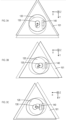
- Fig. 2 is a diagram illustrating the driving source 120, the rotating shaft 130, the acceleration sensor 140, and the vibration isolating unit 160 taken along the A-A line of Fig. 1 .
- Figs. 3A to 3C are diagrams illustrating a state that the driving source 120, the rotating shaft 130, the acceleration sensor 140, and the vibration isolating unit 160 vibrate. Positions indicated by dotted lines in Figs. 3A to 3C are original positions and Figs. 3A to 3C illustrate states shifted in mutually-different directions.
- the vibration isolating unit 160 has a role of attenuating vibration caused by imbalance of the rotor 110.
- the vibration isolating unit 160 may be composed of a supporting plate 161 which grips the driving source 120 and a plurality of vibration isolating springs 162, one ends of which are fixed on the casing 190 and the other ends of which are fixed on the supporting plate 161, as illustrated in Figs. 1 and 2 .
- an elastic body such as rubber may be used instead of the vibration isolating spring.
- the acceleration sensor 140 outputs values indicating acceleration in at least two different directions which are orthogonal to the axial direction of the rotating shaft. More specifically, the acceleration sensor 140 is attached to the driving source 120 or the supporting plate 161 and measures acceleration of vibration of the driving source 120 which is generated along with rotation of the rotor 110.
- the acceleration sensor 140 may be attached to the upper surface of the driving source 120 as illustrated in Figs. 1 and 2 or may be attached on the lower part of the driving source 120, for example.
- the two directions are orthogonal to each other, in which one is referred to as the X axis direction and the other is referred to as the Y axis direction.
- the axial direction of the rotating shaft 130 is referred to as the Z axis direction.
- a value indicating acceleration in the X axis direction is denoted by a X and a value indicating acceleration in the Y axis direction is denoted by a Y .
- a "value indicating acceleration” is not only a value accorded with acceleration but also a value proportional to acceleration and a value discretely indicating a value proportional to acceleration such as a digital signal.
- R is a value indicating a magnitude of shift (amplitude) and indicating displacement of the rotating shaft 130, the vibration isolating unit 160, and the like, from stationary states thereof.
- ⁇ denotes an angular velocity of the rotating shaft 130.
- Fig. 4 illustrates a relation between a rotation speed and acceleration for each imbalance in a certain centrifuge.
- the horizontal axis indicates a rotation speed (rpm) and the vertical axis indicates an acceleration corresponding value (bit), and the cases of rotor imbalance of 0 g, 12 g, 24 g, and 36 g are shown.
- the acceleration corresponding value (bit) in the vertical axis is a value obtained by calculating (a Z 2 +a Y 2 +a Z 2 ) 1/2 with outputs (a X , a Y , a Z ) from the acceleration sensor in three orthogonal axial directions.
- 256 bits correspond to 1 G (approximately 9.8 m/s 2 ).
- acceleration Since acceleration is proportional to a square of an angular velocity, the acceleration corresponding value increases as the rotation speed increases in the example of Fig. 4 . Further, there is a range having large acceleration corresponding values around 1000 rpm of rotation speed in the example of Fig. 4 .
- This range is a range of a state in which vibration of the rotor 110 is resonated, and the range is referred to as a "resonance range" in the present specification.
- the "resonance range” is a range corresponding to a specific angular velocity at which displacement of the rotating shaft of the rotor 110 increases and the "resonance range” is determined depending on a configuration of the vibration isolating unit 160, mass of the rotor 110, and the like.
- an angular velocity at which a resonance point is obtained varies every time in a certain range because of an influence of mass of a sample to be housed in the rotor 110.
- a range corresponding to an angular velocity at which a resonance point can be obtained in consideration of an influence of mass of a sample may be referred to as a resonance range.
- a range also including a range corresponding to an angular velocity at which a half of a displacement conversion value on a resonance point can be obtained may be referred to as a resonance range.
- a resonance range is often a part of a range from 500 to 1500 rpm.
- Corresponding to an angular velocity indicates that a value may be an angular velocity itself or another certain parameter having a certain relation with an angular velocity. Since a rotation speed is proportional to an angular velocity, a rotation speed is one of values corresponding to an angular velocity, for example.
- a "range corresponding to an angular velocity” may be a range defined by an angular velocity or may be a range defined by a value corresponding to an angular velocity such as a rotation speed.
- Fig. 5 illustrates a relation between a rotation speed and displacement for each imbalance in a certain centrifuge.
- This drawing shows a value obtained by converting the vertical axis in the example of Fig. 4 into displacement (displacement conversion value).
- a displacement conversion value is a value obtained by dividing measured acceleration by the square of the measured acceleration.
- Fig. 5 shows a unit of a displacement conversion value as ⁇ m, but a value obtained by multiplying a unit of a length by a coefficient may be employed instead of a unit of actual length as is the case with Fig. 4 .
- Figs. 4 and 5 show, acceleration increases when a rotation speed is high and displacement increases in the resonance range.
- Fig. 6 is a diagram illustrating a processing flow of the control unit 150.
- the control unit 150 acquires values indicating acceleration and outputted by the acceleration sensor 140 (S10).
- the control unit 150 obtains a displacement conversion value (S20).
- the "displacement conversion value” is a value corresponding to a value, which is obtained by dividing a value which is proportional to acceleration based on a value indicating acceleration and outputted by the acceleration sensor 140, by a value which is proportional to the square of an angular velocity of the rotor 110.
- the control unit 150 stops rotation of the rotor (S40).
- the displacement determination criterion there is a criterion for making determination depending on whether or not to excess a threshold value which is determined as the dotted line (A) shown in Fig. 5 , for example.
- the displacement determination criterion can prevent the rotor, the bucket, the rotating shaft, or the like from coming into contact with the chamber or the like irrespective of an angular velocity (rotation speed).
- a method for setting a displacement determination criterion in a predetermined range, below a resonance range, of a value corresponding to an angular velocity as (B) shown in Fig. 5 there is a method for setting a displacement determination criterion in a predetermined range, below a resonance range, of a value corresponding to an angular velocity as (B) shown in Fig. 5 .
- the "value corresponding to an angular velocity” includes an angular velocity itself and a rotation speed, for example.
- the "value corresponding to an angular velocity” is not limited to these but includes a value obtained by multiplying an angular velocity by an arbitrary constant.
- the "predetermined range, below a resonance range, of a value corresponding to an angular velocity” is a range which is defined for each centrifuge and a range which is below a value corresponding to the lowest angular velocity in the resonance range obtained in consideration of a sample which can be housed as well.
- the displacement determination criterion is set in a range from 400 to 600 rpm of rotation speed.
- the control unit 150 obtains a displacement conversion value and confirms whether or not the displacement conversion value satisfies a displacement determination criterion. If the range is set as from 400 to 600 rpm, vibration caused by imbalance can be appropriately detected even when the resonance range is changed because of deterioration of the vibration isolating spring 162 or an elastic body such as rubber used instead of the vibration isolating spring 162 or use environments such as a temperature.
- the determination can be made when displacement is small, easily preventing the rotor, the bucket, the rotating shaft, or the like from coming into contact with the chamber or the like.
- a displacement conversion value which is smaller than the maximum value of a displacement conversion value in a resonance range in the allowable maximum imbalance is included in a range satisfying the displacement determination criterion, rotation of the rotor 110 can be stopped before the displacement becomes large, being able to further prevent the contact.
- imbalance less than 24 g is defined as allowable imbalance.
- a displacement conversion value changes depending on the difference in mass of an entire sample and the like. Therefore, a displacement determination criterion may be defined in consideration of this change.
- a threshold value is set as 900 ⁇ m in the range from 400 to 600 rpm so that the displacement determination criterion is satisfied as long as imbalance is 24 g or greater irrespective of mass of an entire sample.
- This threshold value is smaller than the maximum value (approximately 2700 ⁇ m) of a displacement conversion value in the resonance range for the case of 12 g imbalance which is smaller imbalance than the allowable maximum imbalance. That is, if a displacement determination criterion is set in a predetermined range, below a resonance range, of a value corresponding to an angular velocity, rotation of the rotor can be stopped when a displacement conversion value which is smaller than the maximum value of an allowable displacement conversion value is obtained.
- a range satisfying a displacement determination criterion includes a displacement conversion value which is smaller than the maximum value of a displacement conversion value in a resonance range in the allowable maximum imbalance
- a load on the vibration isolating spring 162 or an elastic body such as rubber used instead of the vibration isolating spring 162 can be put within a range of a using condition assumed in designing even when there is imbalance, providing an advantageous effect that damage and deterioration can be prevented.
- vibration caused by imbalance can be detected with a value converted into displacement without using a displacement sensor. Accordingly, the rotor, the bucket, the rotating shaft, or the like can be prevented from coming into contact with the chamber or the like.
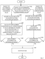
- Fig. 7 illustrates an example of a processing flow using both of a displacement determination criterion and an acceleration determination criterion.
- the control unit 150 confirms whether a value corresponding to an angular velocity is in a range for performing determination based on a displacement conversion value or a range for performing determination based on an acceleration corresponding value (S100).
- the range from 400 to 600 rpm is the range for performing determination based on a displacement conversion value.
- 1500 rpm or greater may be defined as the range for performing determination based on an acceleration corresponding value.
- step S100 the control unit 150 repeats step S100 during operation of the centrifuge 100 when the value is neither in the range for performing determination based on a displacement conversion value nor in the range for performing determination based on an acceleration corresponding value.
- the control unit 150 determines that the value is in the range for performing determination based on a displacement conversion value in step S100, the control unit 150 performs the same processing as those in steps S10 to S40 illustrated in Fig. 6 .
- the control unit 150 determines that the value is in the range for performing determination based on an acceleration corresponding value in step S100, acquires values indicating acceleration from the acceleration sensor 140 (S110).
- Values indicating acceleration may be values indicating acceleration in two different directions orthogonal to the axial direction of the rotating shaft 130 or may also include acceleration in the axial direction of the rotating shaft 130.
- the control unit 150 calculates an acceleration corresponding value which is a value corresponding to acceleration (S120). Specifically, the calculation may be performed with formula (1) or formula (2). Further, a displacement conversion value is not calculated in step S120, so that calculation of square root may be omitted as a X 2 +a Y 2 or a X 2 +a Y 2 +a Z 2 , for example.
- the control unit 150 compares the obtained acceleration corresponding value with the acceleration determination criterion (S130), and the control unit 150 stops rotation of the rotor when the acceleration determination criterion is satisfied (S40).
- the acceleration determination criterion is satisfied when an acceleration corresponding value based on a X 2 +a Y 2 or a X 2 +a Y 2 +a Z 2 exceeds a criterion expressed by a curved line or a straight line at an angular velocity above a resonance range. More specifically, an acceleration corresponding value is set to be a value proportional to (a X 2 +a Y 2 ) 1/2 or (a X 2 +a Y 2 +a Z 2 ) 1/2 .
- the acceleration determination criterion is satisfied when an acceleration corresponding value exceeds a criterion (b ⁇ 2 +c ⁇ +d+offset value), which is expressed by a quadratic function of an angular velocity of the rotating shaft 130, at an angular velocity above the resonance range (for example, 1500 rpm or greater) as described in Patent Literature 1.
- a criterion (b ⁇ 2 +c ⁇ +d+offset value)
- an acceleration corresponding value may be set to a value proportional to a X 2 +a Y 2 or a X 2 +a Y 2 +a Z 2 and a criterion may be expressed by a quartic function.
- an acceleration corresponding value may be set to a value proportional to (a X 2 +a Y 2 ) 1/4 or (a X 2 +a Y 2 +a Z 2 ) 1/4 and a criterion may be expressed by a linear function.
- the acceleration corresponding value obtained with formula (1) or formula (2) may be used.
- a range of a value corresponding to all acceleration may be defined as a range for performing determination based on an acceleration corresponding value
- an acceleration corresponding value of 1200 bits in Fig. 4 may be set to a threshold value, and it may be determined that an acceleration corresponding value satisfies the acceleration determination criterion when the acceleration corresponding value is equal to or greater than the threshold value, for example.
- the acceleration sensor 140 can singly prevent contact caused by large vibration and also prevent damage by stress caused by large acceleration. Further, as described above, a displacement determination criterion which is a fixed value is used at an angular velocity which is below a resonance range and an acceleration determination criterion which is an approximate curve is used at an angular velocity which is above the resonance range. Accordingly, damage of the centrifuge can be prevented, further, imbalance can be detected at an earlier stage than prior art after start of rotation, and advantageous effects such as deterioration prevention can be expected.
Landscapes
- Centrifugal Separators (AREA)
Description
- The present invention relates to a centrifuge that detects an imbalanced state and controls rotation.
- Imbalance is generated on a rotor in which a sample is placed (a state that the center of gravity of the entire rotor including the sample is not on a rotating shaft). If this imbalance becomes too large, the rotor, the rotating shaft, or the like swings excessively, causing a failure of a centrifuge.
Patent Literature 1, for example, is known as a technique for detecting swing caused by such imbalance. Specifically,Patent Literature 1 seeks to accurately measure acceleration caused by an imbalance of a balance of a rotor even when rotating at a high speed, by using an acceleration sensor and a control part having a processing speed determined when rotating at a low speed. To this end, a centrifugal separator is disclosed that comprises a rotor, a driving source for rotating the rotor, a rotary shaft for joining the rotor and the driving source, an acceleration sensor and a control part. The acceleration sensor outputs a value of indicating acceleration in two different directions vertical to the axial direction of the rotary shaft. The control part determines an acceleration corresponding value being a value corresponding to the acceleration in the vertical direction to the axial direction of the rotary shaft from a value of indicating the acceleration in the two different directions, and stops rotation of the rotor when the acceleration corresponding value satisfies a criterion of indicating that predetermined acceleration is large. - Patent Literature 1:
Japanese Patent Application Laid Open No. 2017-87178 - The centrifuge of
Patent Literature 1 includes an acceleration sensor that outputs a value indicating acceleration in two different directions orthogonal to an axial direction of a rotating shaft of a rotor. Further, an acceleration corresponding value being a value corresponding to the acceleration in the direction orthogonal to the axial direction of the rotating shaft is obtained from the value indicating the acceleration in the two different directions, and rotation of the rotor is stopped when the acceleration corresponding value satisfies a predetermined determination criterion indicating that acceleration is large. - The centrifuge of
Patent Literature 1 stops rotation of the rotor based on force applied to, for example, a vibration isolating unit of the centrifuge, so that damage caused by stress can be prevented. However, since acceleration is proportional to a radius of vibration and is proportional to the square of an angular velocity, influence of an angular velocity is greater than influence of a radius. Therefore, it is difficult to prevent damage that is caused by a rotor, a bucket, a rotating shaft, or the like coming into contact with a chamber or the like, and that occurs when the rotation speed (angular velocity) is low but displacement of the rotating shaft (a radius of vibration) is large. - In addition, displacement can be also detected if a centrifuge further includes a displacement sensor. However, the centrifuge is to have both of an acceleration sensor and a displacement sensor and to perform processing of signals of these sensors. Accordingly, the centrifuge becomes expensive.
- The present invention has been made in view of such a situation, and an object of the present invention is to prevent damage caused by displacement of a rotating shaft by using an acceleration sensor.
- The present invention provides centrifuges having the features of the appended claims.
- According to an example that is not encompassed by the claims but useful for understanding the present invention, a centrifuge includes a rotor, a driving source that rotates the rotor, a rotating shaft that links the rotor with the driving source, an acceleration sensor, and a control unit. The acceleration sensor outputs a value indicating acceleration in at least two different directions which are orthogonal to an axial direction of the rotating shaft. The control unit obtains a displacement conversion value corresponding to a value, which is obtained by dividing a value which is proportional to acceleration based on a value indicating acceleration and outputted by the acceleration sensor, by a value which is proportional to a square of an angular velocity of the rotor, and stops rotation of the rotor when the displacement conversion value satisfies a displacement determination criterion which is predetermined and indicates that displacement is large.
- According to the centrifuge of the present invention, vibration caused by imbalance can be detected with a value converted into displacement without using a displacement sensor. Accordingly, a rotor, a bucket, a rotating shaft, or the like can be prevented from coming into contact with a chamber or the like.
-
-
Fig. 1 is a diagram illustrating a configuration example of a centrifuge according to the present invention. -
Fig. 2 is a diagram illustrating adriving source 120, arotating shaft 130, anacceleration sensor 140, and avibration isolating unit 160 taken along the A-A line ofFig. 1 . -
Fig. 3A is a first diagram illustrating a state that thedriving source 120, therotating shaft 130, theacceleration sensor 140, and thevibration isolating unit 160 vibrate. -
Fig. 3B is a second diagram illustrating the state that thedriving source 120, therotating shaft 130, theacceleration sensor 140, and thevibration isolating unit 160 vibrate. -
Fig. 3C is a third diagram illustrating the state that thedriving source 120, therotating shaft 130, theacceleration sensor 140, and thevibration isolating unit 160 vibrate. -
Fig. 4 is a diagram illustrating a relation between a rotation speed and acceleration for each imbalance in a certain centrifuge. -
Fig. 5 is a diagram illustrating a relation between a rotation speed and displacement for each imbalance in a certain centrifuge. -
Fig. 6 is a diagram illustrating a processing flow of a control unit. -
Fig. 7 is a diagram illustrating a processing flow using both of a displacement determination criterion and an acceleration determination criterion. - An embodiment according to the present invention is described in detail below. Components having the mutually same functions are provided with the same reference characters and duplicate description thereof is omitted.
-
Fig. 1 illustrates a configuration example of a centrifuge according to a first embodiment. Acentrifuge 100 includes acasing 190, achamber 192, an openable andclosable chamber lid 191, arotor 110 which is housed in thechamber 192, adriving source 120 which rotates therotor 110, arotating shaft 130 which links therotor 110 with thedriving source 120, anacceleration sensor 140, acontrol unit 150, and avibration isolating unit 160. -
Fig. 2 is a diagram illustrating thedriving source 120, therotating shaft 130, theacceleration sensor 140, and thevibration isolating unit 160 taken along the A-A line ofFig. 1 .Figs. 3A to 3C are diagrams illustrating a state that thedriving source 120, therotating shaft 130, theacceleration sensor 140, and thevibration isolating unit 160 vibrate. Positions indicated by dotted lines inFigs. 3A to 3C are original positions andFigs. 3A to 3C illustrate states shifted in mutually-different directions. - There are some types of rotors as the
rotor 110 such as a type provided with a hole for housing a test tube or the like and a type for attaching a bucket for housing a tube rack, in which samples are to be put, to therotor 110. However, the present invention is applicable irrespective of a type of therotor 110, so that the type of therotor 110 is not limited. Thevibration isolating unit 160 has a role of attenuating vibration caused by imbalance of therotor 110. For example, thevibration isolating unit 160 may be composed of a supportingplate 161 which grips thedriving source 120 and a plurality ofvibration isolating springs 162, one ends of which are fixed on thecasing 190 and the other ends of which are fixed on the supportingplate 161, as illustrated inFigs. 1 and 2 . Further, an elastic body such as rubber may be used instead of the vibration isolating spring. - The
acceleration sensor 140 outputs values indicating acceleration in at least two different directions which are orthogonal to the axial direction of the rotating shaft. More specifically, theacceleration sensor 140 is attached to thedriving source 120 or the supportingplate 161 and measures acceleration of vibration of thedriving source 120 which is generated along with rotation of therotor 110. Theacceleration sensor 140 may be attached to the upper surface of thedriving source 120 as illustrated inFigs. 1 and 2 or may be attached on the lower part of thedriving source 120, for example. In the first embodiment, the two directions are orthogonal to each other, in which one is referred to as the X axis direction and the other is referred to as the Y axis direction. Further, the axial direction of the rotatingshaft 130 is referred to as the Z axis direction. Furthermore, a value indicating acceleration in the X axis direction is denoted by aX and a value indicating acceleration in the Y axis direction is denoted by aY. Here, a "value indicating acceleration" is not only a value accorded with acceleration but also a value proportional to acceleration and a value discretely indicating a value proportional to acceleration such as a digital signal. - aX and aY which are outputs from the
acceleration sensor 140 of the first embodiment are values indicating acceleration in the directions which are mutually orthogonal, and when inclination of therotating shaft 130 is ignorable,
rotating shaft 130, thevibration isolating unit 160, and the like, from stationary states thereof. ω denotes an angular velocity of therotating shaft 130. - When displacement R is increased, inclination of the
rotating shaft 130 is increased, and vibration in the Z direction accordingly becomes unignorable. In the case where vibration in the Z direction is not ignorable either, when a value indicating acceleration in the Z axis direction is denoted by aZ,
acceleration sensor 140 also outputs the value aZ indicating acceleration in the Z direction of vibration of the driving source 120 (in the axial direction of the rotating shaft 130) caused by rotation of therotor 110. -
Fig. 4 illustrates a relation between a rotation speed and acceleration for each imbalance in a certain centrifuge. The horizontal axis indicates a rotation speed (rpm) and the vertical axis indicates an acceleration corresponding value (bit), and the cases of rotor imbalance of 0 g, 12 g, 24 g, and 36 g are shown. The acceleration corresponding value (bit) in the vertical axis is a value obtained by calculating (aZ 2+aY 2+aZ 2)1/2 with outputs (aX, aY, aZ) from the acceleration sensor in three orthogonal axial directions. 256 bits correspond to 1 G (approximately 9.8 m/s2). Since acceleration is proportional to a square of an angular velocity, the acceleration corresponding value increases as the rotation speed increases in the example ofFig. 4 . Further, there is a range having large acceleration corresponding values around 1000 rpm of rotation speed in the example ofFig. 4 . This range is a range of a state in which vibration of therotor 110 is resonated, and the range is referred to as a "resonance range" in the present specification. The "resonance range" is a range corresponding to a specific angular velocity at which displacement of the rotating shaft of therotor 110 increases and the "resonance range" is determined depending on a configuration of thevibration isolating unit 160, mass of therotor 110, and the like. However, an angular velocity at which a resonance point is obtained varies every time in a certain range because of an influence of mass of a sample to be housed in therotor 110. For example, a range corresponding to an angular velocity at which a resonance point can be obtained in consideration of an influence of mass of a sample may be referred to as a resonance range. Further, a range also including a range corresponding to an angular velocity at which a half of a displacement conversion value on a resonance point can be obtained may be referred to as a resonance range. In the case of a general centrifuge, a resonance range is often a part of a range from 500 to 1500 rpm. "Corresponding to an angular velocity" indicates that a value may be an angular velocity itself or another certain parameter having a certain relation with an angular velocity. Since a rotation speed is proportional to an angular velocity, a rotation speed is one of values corresponding to an angular velocity, for example. A "range corresponding to an angular velocity" may be a range defined by an angular velocity or may be a range defined by a value corresponding to an angular velocity such as a rotation speed. -
Fig. 5 illustrates a relation between a rotation speed and displacement for each imbalance in a certain centrifuge. This drawing shows a value obtained by converting the vertical axis in the example ofFig. 4 into displacement (displacement conversion value). A displacement conversion value is a value obtained by dividing measured acceleration by the square of the measured acceleration.Fig. 5 shows a unit of a displacement conversion value as µm, but a value obtained by multiplying a unit of a length by a coefficient may be employed instead of a unit of actual length as is the case withFig. 4 . AsFigs. 4 and 5 show, acceleration increases when a rotation speed is high and displacement increases in the resonance range. -
Fig. 6 is a diagram illustrating a processing flow of thecontrol unit 150. Thecontrol unit 150 acquires values indicating acceleration and outputted by the acceleration sensor 140 (S10). Thecontrol unit 150 obtains a displacement conversion value (S20). The "displacement conversion value" is a value corresponding to a value, which is obtained by dividing a value which is proportional to acceleration based on a value indicating acceleration and outputted by theacceleration sensor 140, by a value which is proportional to the square of an angular velocity of therotor 110. When the displacement conversion value satisfies a predetermined displacement determination criterion indicating large displacement (S30), thecontrol unit 150 stops rotation of the rotor (S40). - As the displacement determination criterion, there is a criterion for making determination depending on whether or not to excess a threshold value which is determined as the dotted line (A) shown in
Fig. 5 , for example. The displacement determination criterion can prevent the rotor, the bucket, the rotating shaft, or the like from coming into contact with the chamber or the like irrespective of an angular velocity (rotation speed). - As another example, there is a method for setting a displacement determination criterion in a predetermined range, below a resonance range, of a value corresponding to an angular velocity as (B) shown in
Fig. 5 . The "value corresponding to an angular velocity" includes an angular velocity itself and a rotation speed, for example. However, the "value corresponding to an angular velocity" is not limited to these but includes a value obtained by multiplying an angular velocity by an arbitrary constant. The "predetermined range, below a resonance range, of a value corresponding to an angular velocity" is a range which is defined for each centrifuge and a range which is below a value corresponding to the lowest angular velocity in the resonance range obtained in consideration of a sample which can be housed as well. In the example of (B) inFig. 5 , the displacement determination criterion is set in a range from 400 to 600 rpm of rotation speed. That is, when a value corresponding to an angular velocity of therotor 110 is in the predetermined range, below a resonance range, of a value corresponding to an angular velocity (for example, 400 to 600 rpm), thecontrol unit 150 obtains a displacement conversion value and confirms whether or not the displacement conversion value satisfies a displacement determination criterion. If the range is set as from 400 to 600 rpm, vibration caused by imbalance can be appropriately detected even when the resonance range is changed because of deterioration of thevibration isolating spring 162 or an elastic body such as rubber used instead of thevibration isolating spring 162 or use environments such as a temperature. - If determination is made at an angular velocity below the resonance range, the determination can be made when displacement is small, easily preventing the rotor, the bucket, the rotating shaft, or the like from coming into contact with the chamber or the like. Especially, if a displacement conversion value which is smaller than the maximum value of a displacement conversion value in a resonance range in the allowable maximum imbalance is included in a range satisfying the displacement determination criterion, rotation of the
rotor 110 can be stopped before the displacement becomes large, being able to further prevent the contact. For example, imbalance less than 24 g is defined as allowable imbalance. Here, even with the same imbalance, a displacement conversion value changes depending on the difference in mass of an entire sample and the like. Therefore, a displacement determination criterion may be defined in consideration of this change. In the example of (B) inFig. 5 , a threshold value is set as 900 µm in the range from 400 to 600 rpm so that the displacement determination criterion is satisfied as long as imbalance is 24 g or greater irrespective of mass of an entire sample. This threshold value is smaller than the maximum value (approximately 2700 µm) of a displacement conversion value in the resonance range for the case of 12 g imbalance which is smaller imbalance than the allowable maximum imbalance. That is, if a displacement determination criterion is set in a predetermined range, below a resonance range, of a value corresponding to an angular velocity, rotation of the rotor can be stopped when a displacement conversion value which is smaller than the maximum value of an allowable displacement conversion value is obtained. - Further, if imbalance determination based on a displacement conversion value is performed in a predetermined range, below a resonance range, of a value corresponding to an angular velocity, rotation of the centrifuge can be stopped at lower rotation. That is, time from start to end of rotation of the centrifuge with imbalance can be shortened, also providing an advantageous effect that waiting time of a user can be shortened. Further, if a range satisfying a displacement determination criterion includes a displacement conversion value which is smaller than the maximum value of a displacement conversion value in a resonance range in the allowable maximum imbalance, a load on the
vibration isolating spring 162 or an elastic body such as rubber used instead of thevibration isolating spring 162 can be put within a range of a using condition assumed in designing even when there is imbalance, providing an advantageous effect that damage and deterioration can be prevented. - According to the
centrifuge 100, vibration caused by imbalance can be detected with a value converted into displacement without using a displacement sensor. Accordingly, the rotor, the bucket, the rotating shaft, or the like can be prevented from coming into contact with the chamber or the like. - Further, if stop control based on an acceleration corresponding value is performed, damage caused by stress applied to the
vibration isolating unit 160 or the like can be also prevented.Fig. 7 illustrates an example of a processing flow using both of a displacement determination criterion and an acceleration determination criterion. Thecontrol unit 150 confirms whether a value corresponding to an angular velocity is in a range for performing determination based on a displacement conversion value or a range for performing determination based on an acceleration corresponding value (S100). In the example of (B) inFig. 5 , the range from 400 to 600 rpm is the range for performing determination based on a displacement conversion value. Further, 1500 rpm or greater may be defined as the range for performing determination based on an acceleration corresponding value. If a range for performing determination based on a displacement conversion value and a range for performing determination based on an acceleration corresponding value are thus set, determination based on a displacement conversion value can be performed when a value corresponding to an angular velocity is below a resonance range, while determination based on an acceleration corresponding value can be performed when the value corresponding to an angular velocity is above the resonance range. Thecontrol unit 150 repeats step S100 during operation of thecentrifuge 100 when the value is neither in the range for performing determination based on a displacement conversion value nor in the range for performing determination based on an acceleration corresponding value. When thecontrol unit 150 determines that the value is in the range for performing determination based on a displacement conversion value in step S100, thecontrol unit 150 performs the same processing as those in steps S10 to S40 illustrated inFig. 6 . - When the
control unit 150 determines that the value is in the range for performing determination based on an acceleration corresponding value in step S100, thecontrol unit 150 acquires values indicating acceleration from the acceleration sensor 140 (S110). Values indicating acceleration may be values indicating acceleration in two different directions orthogonal to the axial direction of therotating shaft 130 or may also include acceleration in the axial direction of therotating shaft 130. Thecontrol unit 150 calculates an acceleration corresponding value which is a value corresponding to acceleration (S120). Specifically, the calculation may be performed with formula (1) or formula (2). Further, a displacement conversion value is not calculated in step S120, so that calculation of square root may be omitted as aX 2+aY 2 or aX 2+aY 2+aZ 2, for example. Thecontrol unit 150 compares the obtained acceleration corresponding value with the acceleration determination criterion (S130), and thecontrol unit 150 stops rotation of the rotor when the acceleration determination criterion is satisfied (S40). For example, it may be defined that the acceleration determination criterion is satisfied when an acceleration corresponding value based on aX 2+aY 2 or aX 2+aY 2+aZ 2 exceeds a criterion expressed by a curved line or a straight line at an angular velocity above a resonance range. More specifically, an acceleration corresponding value is set to be a value proportional to (aX 2+aY 2)1/2 or (aX 2+aY 2+aZ 2)1/2. Then, it may be defined that the acceleration determination criterion is satisfied when an acceleration corresponding value exceeds a criterion (bω2+cω+d+offset value), which is expressed by a quadratic function of an angular velocity of therotating shaft 130, at an angular velocity above the resonance range (for example, 1500 rpm or greater) as described inPatent Literature 1. Here, as is the case withPatent Literature 1, an acceleration corresponding value may be set to a value proportional to aX 2+aY 2 or aX 2+aY 2+aZ 2 and a criterion may be expressed by a quartic function. Further, an acceleration corresponding value may be set to a value proportional to (aX 2+aY 2)1/4 or (aX 2+aY 2+aZ 2)1/4 and a criterion may be expressed by a linear function. Furthermore, the acceleration corresponding value obtained with formula (1) or formula (2) may be used. In this case, a range of a value corresponding to all acceleration may be defined as a range for performing determination based on an acceleration corresponding value, an acceleration corresponding value of 1200 bits inFig. 4 may be set to a threshold value, and it may be determined that an acceleration corresponding value satisfies the acceleration determination criterion when the acceleration corresponding value is equal to or greater than the threshold value, for example. - In the processing flow illustrated in
Fig. 7 , theacceleration sensor 140 can singly prevent contact caused by large vibration and also prevent damage by stress caused by large acceleration. Further, as described above, a displacement determination criterion which is a fixed value is used at an angular velocity which is below a resonance range and an acceleration determination criterion which is an approximate curve is used at an angular velocity which is above the resonance range. Accordingly, damage of the centrifuge can be prevented, further, imbalance can be detected at an earlier stage than prior art after start of rotation, and advantageous effects such as deterioration prevention can be expected. -
- 100
- centrifuge
- 110
- rotor
- 120
- driving source
- 130
- rotating shaft
- 140
- acceleration sensor
- 150
- control unit
- 160
- vibration isolating unit
- 161
- supporting plate
- 162
- vibration isolating spring
- 190
- casing
- 191
- chamber lid
- 192
- chamber
Claims (5)
- A centrifuge (100) comprising:a rotor (110);a driving source (120) that rotates the rotor (110);a rotating shaft (130) that links the rotor (110) with the driving source (120);an acceleration sensor (140) that outputs a value indicating acceleration in at least two different directions which are orthogonal to an axial direction of the rotating shaft (130); anda control unit (150) that obtains a displacement conversion value corresponding to a value, the value being obtained by dividing a value which is proportional to acceleration based on a value indicating acceleration and outputted by the acceleration sensor (140), by a value which is proportional to a square of an angular velocity of the rotor (110), and that stops rotation of the rotor (110) when the displacement conversion value satisfies a displacement determination criterion which is predetermined and indicates that displacement is large,whereina range of a value that corresponds to an angular velocity at which displacement of the rotating shaft (130) of the rotor (110) increases due to resonance is defined to be a resonance range,the control unit (150) obtains a displacement conversion value when a value corresponding to an angular velocity of the rotor (110) is in a predetermined range of a value corresponding to an angular velocity, the range being below the resonance range, so as to confirm whether the displacement conversion value satisfies the displacement determination criterion, anda case of a displacement conversion value, the displacement conversion value being smaller than a maximum value of a displacement conversion value in the resonance range in allowable maximum imbalance, is included in a range satisfying the displacement determination criterion.
- The centrifuge according to Claim 1, wherein the control unit (150) obtains an acceleration corresponding value, the acceleration corresponding value being a value corresponding to acceleration based on a value indicating acceleration and outputted by the acceleration sensor (140), and stops rotation of the rotor (110) when the acceleration corresponding value satisfies an acceleration determination criterion which is predetermined and indicates that acceleration is large.
- The centrifuge according to Claim 2, wherein the control unit (150) confirms whether the acceleration corresponding value satisfies the acceleration determination criterion when a value corresponding to an angular velocity of the rotor (110) is above the resonance range.
- A centrifuge (100) comprising:a rotor (110);a driving source (120) that rotates the rotor (110);a rotating shaft (130) that links the rotor (110) with the driving source (120);an acceleration sensor (140) that outputs a value indicating acceleration in at least two different directions which are orthogonal to an axial direction of the rotating shaft (130); anda control unit (150) that obtains a displacement conversion value corresponding to a value, the value being obtained by dividing a value which is proportional to acceleration based on a value indicating acceleration and outputted by the acceleration sensor (140), by a value which is proportional to a square of an angular velocity of the rotor (110), and that stops rotation of the rotor (110) when the displacement conversion value satisfies a displacement determination criterion which is predetermined and indicates that displacement is large,whereina range of a value that corresponds to an angular velocity at which displacement of the rotating shaft (130) of the rotor (110) increases due to resonance is defined to be a resonance range,the control unit (150) obtains a displacement conversion value when a value corresponding to an angular velocity of the rotor (110) is in a predetermined range of a value corresponding to an angular velocity, the range being below the resonance range, so as to confirm whether the displacement conversion value satisfies the displacement determination criterion,the control unit (150) obtains an acceleration corresponding value, the acceleration corresponding value being a value corresponding to acceleration based on a value indicating acceleration and outputted by the acceleration sensor (140), and stops rotation of the rotor (110) when the acceleration corresponding value satisfies an acceleration determination criterion which is predetermined and indicates that acceleration is large, andthe control unit (150) confirms whether the acceleration corresponding value satisfies the acceleration determination criterion when a value corresponding to an angular velocity of the rotor (110) is above the resonance range.
- The centrifuge according to any one of Claims 1 to 4, wherein the acceleration sensor (140) also outputs a value indicating acceleration in an axial direction of the rotating shaft (130).
Applications Claiming Priority (2)
| Application Number | Priority Date | Filing Date | Title |
|---|---|---|---|
| JP2018010201A JP7089884B2 (en) | 2018-01-25 | 2018-01-25 | centrifuge |
| PCT/JP2019/000519 WO2019146415A1 (en) | 2018-01-25 | 2019-01-10 | Centrifugal separator |
Publications (4)
| Publication Number | Publication Date |
|---|---|
| EP3744430A1 EP3744430A1 (en) | 2020-12-02 |
| EP3744430A4 EP3744430A4 (en) | 2021-11-24 |
| EP3744430B1 true EP3744430B1 (en) | 2025-06-04 |
| EP3744430B8 EP3744430B8 (en) | 2025-07-09 |
Family
ID=67394949
Family Applications (1)
| Application Number | Title | Priority Date | Filing Date |
|---|---|---|---|
| EP19743823.7A Active EP3744430B8 (en) | 2018-01-25 | 2019-01-10 | Centrifuge |
Country Status (5)
| Country | Link |
|---|---|
| US (1) | US11958063B2 (en) |
| EP (1) | EP3744430B8 (en) |
| JP (1) | JP7089884B2 (en) |
| CN (1) | CN111629833B (en) |
| WO (1) | WO2019146415A1 (en) |
Families Citing this family (2)
| Publication number | Priority date | Publication date | Assignee | Title |
|---|---|---|---|---|
| CN110702347A (en) * | 2019-11-12 | 2020-01-17 | 苏州苏试试验集团股份有限公司 | A kind of vibration centrifugal composite test equipment and its control method |
| CN114733655B (en) * | 2022-06-13 | 2022-08-19 | 江苏省计量科学研究院(江苏省能源计量数据中心) | Detection device and detection method for centrifugal blood component separator |
Family Cites Families (13)
| Publication number | Priority date | Publication date | Assignee | Title |
|---|---|---|---|---|
| JPH0634749U (en) * | 1992-10-16 | 1994-05-10 | 日立工機株式会社 | centrifuge |
| US6635007B2 (en) * | 2000-07-17 | 2003-10-21 | Thermo Iec, Inc. | Method and apparatus for detecting and controlling imbalance conditions in a centrifuge system |
| JP4593822B2 (en) * | 2001-04-13 | 2010-12-08 | 日立工機株式会社 | Centrifuge |
| JP4352844B2 (en) * | 2003-10-09 | 2009-10-28 | 日立工機株式会社 | Centrifuge |
| JP4260097B2 (en) * | 2004-10-27 | 2009-04-30 | シャープ株式会社 | Washing machine |
| KR101042771B1 (en) * | 2008-09-16 | 2011-06-20 | 주식회사 한랩 | Control Method of Automatic Balance Centrifuge with Balancer |
| CN201510945U (en) * | 2009-10-23 | 2010-06-23 | 湖南湘仪实验室仪器开发有限公司 | Centrifuge imbalance protection device of angle deviation sensor |
| CN202962688U (en) * | 2012-11-23 | 2013-06-05 | 湖南吉尔森科技发展有限公司 | Protective equipment of centrifugal machine |
| CN102921567B (en) * | 2012-11-23 | 2015-05-20 | 湖南吉尔森科技发展有限公司 | Protection method and protection equipment for centrifugal machine |
| DE102014116527B4 (en) * | 2014-11-12 | 2020-01-23 | Andreas Hettich Gmbh & Co. Kg | Centrifuge and method for detecting unbalance in the centrifuge |
| CN204535723U (en) * | 2015-04-21 | 2015-08-05 | 中国工程物理研究院总体工程研究所 | A kind of dynamic precision hydro-extractor system |
| JP6640536B2 (en) * | 2015-11-16 | 2020-02-05 | 株式会社久保田製作所 | centrifuge |
| JP6192860B1 (en) | 2016-07-13 | 2017-09-06 | 株式会社久保田製作所 | Rotor mounting structure and centrifuge |
-
2018
- 2018-01-25 JP JP2018010201A patent/JP7089884B2/en active Active
-
2019
- 2019-01-10 US US16/961,838 patent/US11958063B2/en active Active
- 2019-01-10 EP EP19743823.7A patent/EP3744430B8/en active Active
- 2019-01-10 WO PCT/JP2019/000519 patent/WO2019146415A1/en not_active Ceased
- 2019-01-10 CN CN201980008556.6A patent/CN111629833B/en active Active
Also Published As
| Publication number | Publication date |
|---|---|
| EP3744430A4 (en) | 2021-11-24 |
| WO2019146415A1 (en) | 2019-08-01 |
| JP7089884B2 (en) | 2022-06-23 |
| CN111629833A (en) | 2020-09-04 |
| EP3744430A1 (en) | 2020-12-02 |
| US11958063B2 (en) | 2024-04-16 |
| JP2019126777A (en) | 2019-08-01 |
| CN111629833B (en) | 2021-12-07 |
| US20200384483A1 (en) | 2020-12-10 |
| EP3744430B8 (en) | 2025-07-09 |
Similar Documents
| Publication | Publication Date | Title |
|---|---|---|
| KR100986744B1 (en) | Automatic Balancing Centrifuge and its Control Method | |
| KR100470068B1 (en) | automatic balance adjusting centrifuge apparatus | |
| EP3839468B1 (en) | Method for balancing a rotor | |
| EP3378566B1 (en) | Centrifuge | |
| US7055368B2 (en) | Automatic calibration of an imbalance detector | |
| KR101042771B1 (en) | Control Method of Automatic Balance Centrifuge with Balancer | |
| US12181367B2 (en) | Method and drivetrain test bench for detecting an imbalance and/or a misalignment | |
| EP3744430A1 (en) | Centrifugal separator | |
| CN100333837C (en) | Centrifuge | |
| CN109540390A (en) | The method and dynamic balancing mandrel of high speed rotor removal amount of unbalance | |
| JP5489697B2 (en) | Dynamic balance inspection system for tires | |
| CN101368866B (en) | Method for balancing a vehicle wheel | |
| KR101086313B1 (en) | Diagnosis Device and Diagnosis Method of Vibration Screen | |
| JP4593822B2 (en) | Centrifuge | |
| EP3839469B1 (en) | Rotor balancer | |
| KR100343336B1 (en) | automatic balance adjusting centrifuge apparatus | |
| JPH04122655U (en) | centrifuge | |
| JPH0750012B2 (en) | Portable balancing device | |
| Mohamad et al. | Analytical and experimental study on balancing using influence coefficient method | |
| KR20180045692A (en) | apparatus and method for removing unbalance of rotator | |
| JP4926525B2 (en) | Chassis dynamometer | |
| GB2323932A (en) | Wheel balancing apparatus using positive feedback to cause torsional instability | |
| JPH11304686A (en) | Dispersibility evaluating device for suspension | |
| JPH0724362A (en) | centrifuge |
Legal Events
| Date | Code | Title | Description |
|---|---|---|---|
| STAA | Information on the status of an ep patent application or granted ep patent |
Free format text: STATUS: THE INTERNATIONAL PUBLICATION HAS BEEN MADE |
|
| PUAI | Public reference made under article 153(3) epc to a published international application that has entered the european phase |
Free format text: ORIGINAL CODE: 0009012 |
|
| STAA | Information on the status of an ep patent application or granted ep patent |
Free format text: STATUS: REQUEST FOR EXAMINATION WAS MADE |
|
| 17P | Request for examination filed |
Effective date: 20200825 |
|
| AK | Designated contracting states |
Kind code of ref document: A1 Designated state(s): AL AT BE BG CH CY CZ DE DK EE ES FI FR GB GR HR HU IE IS IT LI LT LU LV MC MK MT NL NO PL PT RO RS SE SI SK SM TR |
|
| AX | Request for extension of the european patent |
Extension state: BA ME |
|
| DAV | Request for validation of the european patent (deleted) | ||
| DAX | Request for extension of the european patent (deleted) | ||
| A4 | Supplementary search report drawn up and despatched |
Effective date: 20211021 |
|
| RIC1 | Information provided on ipc code assigned before grant |
Ipc: B04B 9/14 20060101ALI20211015BHEP Ipc: B04B 13/00 20060101ALI20211015BHEP Ipc: B04B 9/10 20060101ALI20211015BHEP Ipc: B04B 7/06 20060101AFI20211015BHEP |
|
| GRAP | Despatch of communication of intention to grant a patent |
Free format text: ORIGINAL CODE: EPIDOSNIGR1 |
|
| STAA | Information on the status of an ep patent application or granted ep patent |
Free format text: STATUS: GRANT OF PATENT IS INTENDED |
|
| INTG | Intention to grant announced |
Effective date: 20250205 |
|
| GRAS | Grant fee paid |
Free format text: ORIGINAL CODE: EPIDOSNIGR3 |
|
| GRAA | (expected) grant |
Free format text: ORIGINAL CODE: 0009210 |
|
| STAA | Information on the status of an ep patent application or granted ep patent |
Free format text: STATUS: THE PATENT HAS BEEN GRANTED |
|
| AK | Designated contracting states |
Kind code of ref document: B1 Designated state(s): AL AT BE BG CH CY CZ DE DK EE ES FI FR GB GR HR HU IE IS IT LI LT LU LV MC MK MT NL NO PL PT RO RS SE SI SK SM TR |
|
| REG | Reference to a national code |
Ref country code: GB Ref legal event code: FG4D |
|
| REG | Reference to a national code |
Ref country code: CH Ref legal event code: PK Free format text: BERICHTIGUNG B8 Ref country code: CH Ref legal event code: EP |
|
| REG | Reference to a national code |
Ref country code: DE Ref legal event code: R096 Ref document number: 602019070753 Country of ref document: DE |
|
| RAP4 | Party data changed (patent owner data changed or rights of a patent transferred) |
Owner name: KUBOTA MANUFACTURING CORPORATION |
|
| RIN2 | Information on inventor provided after grant (corrected) |
Inventor name: MIKI, CHITOSHI |
|
| REG | Reference to a national code |
Ref country code: IE Ref legal event code: FG4D |
|
| REG | Reference to a national code |
Ref country code: NL Ref legal event code: MP Effective date: 20250604 |
|
| PG25 | Lapsed in a contracting state [announced via postgrant information from national office to epo] |
Ref country code: FI Free format text: LAPSE BECAUSE OF FAILURE TO SUBMIT A TRANSLATION OF THE DESCRIPTION OR TO PAY THE FEE WITHIN THE PRESCRIBED TIME-LIMIT Effective date: 20250604 Ref country code: ES Free format text: LAPSE BECAUSE OF FAILURE TO SUBMIT A TRANSLATION OF THE DESCRIPTION OR TO PAY THE FEE WITHIN THE PRESCRIBED TIME-LIMIT Effective date: 20250604 |
|
| REG | Reference to a national code |
Ref country code: LT Ref legal event code: MG9D |
|
| PG25 | Lapsed in a contracting state [announced via postgrant information from national office to epo] |
Ref country code: NO Free format text: LAPSE BECAUSE OF FAILURE TO SUBMIT A TRANSLATION OF THE DESCRIPTION OR TO PAY THE FEE WITHIN THE PRESCRIBED TIME-LIMIT Effective date: 20250904 Ref country code: GR Free format text: LAPSE BECAUSE OF FAILURE TO SUBMIT A TRANSLATION OF THE DESCRIPTION OR TO PAY THE FEE WITHIN THE PRESCRIBED TIME-LIMIT Effective date: 20250905 |
|
| PG25 | Lapsed in a contracting state [announced via postgrant information from national office to epo] |
Ref country code: PL Free format text: LAPSE BECAUSE OF FAILURE TO SUBMIT A TRANSLATION OF THE DESCRIPTION OR TO PAY THE FEE WITHIN THE PRESCRIBED TIME-LIMIT Effective date: 20250604 |
|
| PG25 | Lapsed in a contracting state [announced via postgrant information from national office to epo] |
Ref country code: BG Free format text: LAPSE BECAUSE OF FAILURE TO SUBMIT A TRANSLATION OF THE DESCRIPTION OR TO PAY THE FEE WITHIN THE PRESCRIBED TIME-LIMIT Effective date: 20250604 |
|
| PG25 | Lapsed in a contracting state [announced via postgrant information from national office to epo] |
Ref country code: HR Free format text: LAPSE BECAUSE OF FAILURE TO SUBMIT A TRANSLATION OF THE DESCRIPTION OR TO PAY THE FEE WITHIN THE PRESCRIBED TIME-LIMIT Effective date: 20250604 |
|
| PG25 | Lapsed in a contracting state [announced via postgrant information from national office to epo] |
Ref country code: RS Free format text: LAPSE BECAUSE OF FAILURE TO SUBMIT A TRANSLATION OF THE DESCRIPTION OR TO PAY THE FEE WITHIN THE PRESCRIBED TIME-LIMIT Effective date: 20250904 |
|
| PG25 | Lapsed in a contracting state [announced via postgrant information from national office to epo] |
Ref country code: LV Free format text: LAPSE BECAUSE OF FAILURE TO SUBMIT A TRANSLATION OF THE DESCRIPTION OR TO PAY THE FEE WITHIN THE PRESCRIBED TIME-LIMIT Effective date: 20250604 |
|
| PG25 | Lapsed in a contracting state [announced via postgrant information from national office to epo] |
Ref country code: NL Free format text: LAPSE BECAUSE OF FAILURE TO SUBMIT A TRANSLATION OF THE DESCRIPTION OR TO PAY THE FEE WITHIN THE PRESCRIBED TIME-LIMIT Effective date: 20250604 |
|
| PG25 | Lapsed in a contracting state [announced via postgrant information from national office to epo] |
Ref country code: PT Free format text: LAPSE BECAUSE OF FAILURE TO SUBMIT A TRANSLATION OF THE DESCRIPTION OR TO PAY THE FEE WITHIN THE PRESCRIBED TIME-LIMIT Effective date: 20251006 |
|
| REG | Reference to a national code |
Ref country code: AT Ref legal event code: MK05 Ref document number: 1799874 Country of ref document: AT Kind code of ref document: T Effective date: 20250604 |
|
| PG25 | Lapsed in a contracting state [announced via postgrant information from national office to epo] |
Ref country code: IS Free format text: LAPSE BECAUSE OF FAILURE TO SUBMIT A TRANSLATION OF THE DESCRIPTION OR TO PAY THE FEE WITHIN THE PRESCRIBED TIME-LIMIT Effective date: 20251004 |
|
| PGFP | Annual fee paid to national office [announced via postgrant information from national office to epo] |
Ref country code: GB Payment date: 20251120 Year of fee payment: 8 |
|
| PG25 | Lapsed in a contracting state [announced via postgrant information from national office to epo] |
Ref country code: SM Free format text: LAPSE BECAUSE OF FAILURE TO SUBMIT A TRANSLATION OF THE DESCRIPTION OR TO PAY THE FEE WITHIN THE PRESCRIBED TIME-LIMIT Effective date: 20250604 Ref country code: AT Free format text: LAPSE BECAUSE OF FAILURE TO SUBMIT A TRANSLATION OF THE DESCRIPTION OR TO PAY THE FEE WITHIN THE PRESCRIBED TIME-LIMIT Effective date: 20250604 |
|
| PG25 | Lapsed in a contracting state [announced via postgrant information from national office to epo] |
Ref country code: CZ Free format text: LAPSE BECAUSE OF FAILURE TO SUBMIT A TRANSLATION OF THE DESCRIPTION OR TO PAY THE FEE WITHIN THE PRESCRIBED TIME-LIMIT Effective date: 20250604 |
|
| PG25 | Lapsed in a contracting state [announced via postgrant information from national office to epo] |
Ref country code: SK Free format text: LAPSE BECAUSE OF FAILURE TO SUBMIT A TRANSLATION OF THE DESCRIPTION OR TO PAY THE FEE WITHIN THE PRESCRIBED TIME-LIMIT Effective date: 20250604 Ref country code: RO Free format text: LAPSE BECAUSE OF FAILURE TO SUBMIT A TRANSLATION OF THE DESCRIPTION OR TO PAY THE FEE WITHIN THE PRESCRIBED TIME-LIMIT Effective date: 20250604 |
|
| PG25 | Lapsed in a contracting state [announced via postgrant information from national office to epo] |
Ref country code: IT Free format text: LAPSE BECAUSE OF FAILURE TO SUBMIT A TRANSLATION OF THE DESCRIPTION OR TO PAY THE FEE WITHIN THE PRESCRIBED TIME-LIMIT Effective date: 20250604 |
|
| REG | Reference to a national code |
Ref country code: DE Ref legal event code: R097 Ref document number: 602019070753 Country of ref document: DE |
|
| PLBE | No opposition filed within time limit |
Free format text: ORIGINAL CODE: 0009261 |
|
| STAA | Information on the status of an ep patent application or granted ep patent |
Free format text: STATUS: NO OPPOSITION FILED WITHIN TIME LIMIT |
|
| PG25 | Lapsed in a contracting state [announced via postgrant information from national office to epo] |
Ref country code: DK Free format text: LAPSE BECAUSE OF FAILURE TO SUBMIT A TRANSLATION OF THE DESCRIPTION OR TO PAY THE FEE WITHIN THE PRESCRIBED TIME-LIMIT Effective date: 20250604 |
|
| PGFP | Annual fee paid to national office [announced via postgrant information from national office to epo] |
Ref country code: DE Payment date: 20260131 Year of fee payment: 8 |
|
| REG | Reference to a national code |
Ref country code: CH Ref legal event code: L10 Free format text: ST27 STATUS EVENT CODE: U-0-0-L10-L00 (AS PROVIDED BY THE NATIONAL OFFICE) Effective date: 20260416 |
|
| PGFP | Annual fee paid to national office [announced via postgrant information from national office to epo] |
Ref country code: FR Payment date: 20260127 Year of fee payment: 8 |
|
| 26N | No opposition filed |
Effective date: 20260305 |