EP3744304A1 - Percussion therapy apparatus and methods thereof - Google Patents
Percussion therapy apparatus and methods thereof Download PDFInfo
- Publication number
- EP3744304A1 EP3744304A1 EP20185497.3A EP20185497A EP3744304A1 EP 3744304 A1 EP3744304 A1 EP 3744304A1 EP 20185497 A EP20185497 A EP 20185497A EP 3744304 A1 EP3744304 A1 EP 3744304A1
- Authority
- EP
- European Patent Office
- Prior art keywords
- illustratively
- percussion
- percussive
- percussor
- therapy apparatus
- Prior art date
- Legal status (The legal status is an assumption and is not a legal conclusion. Google has not performed a legal analysis and makes no representation as to the accuracy of the status listed.)
- Granted
Links
Images






























Classifications
-
- A—HUMAN NECESSITIES
- A61—MEDICAL OR VETERINARY SCIENCE; HYGIENE
- A61H—PHYSICAL THERAPY APPARATUS, e.g. DEVICES FOR LOCATING OR STIMULATING REFLEX POINTS IN THE BODY; ARTIFICIAL RESPIRATION; MASSAGE; BATHING DEVICES FOR SPECIAL THERAPEUTIC OR HYGIENIC PURPOSES OR SPECIFIC PARTS OF THE BODY
- A61H9/00—Pneumatic or hydraulic massage
- A61H9/005—Pneumatic massage
-
- A—HUMAN NECESSITIES
- A61—MEDICAL OR VETERINARY SCIENCE; HYGIENE
- A61H—PHYSICAL THERAPY APPARATUS, e.g. DEVICES FOR LOCATING OR STIMULATING REFLEX POINTS IN THE BODY; ARTIFICIAL RESPIRATION; MASSAGE; BATHING DEVICES FOR SPECIAL THERAPEUTIC OR HYGIENIC PURPOSES OR SPECIFIC PARTS OF THE BODY
- A61H23/00—Percussion or vibration massage, e.g. using supersonic vibration; Suction-vibration massage; Massage with moving diaphragms
- A61H23/02—Percussion or vibration massage, e.g. using supersonic vibration; Suction-vibration massage; Massage with moving diaphragms with electric or magnetic drive
- A61H23/0218—Percussion or vibration massage, e.g. using supersonic vibration; Suction-vibration massage; Massage with moving diaphragms with electric or magnetic drive with alternating magnetic fields producing a translating or oscillating movement
-
- A—HUMAN NECESSITIES
- A61—MEDICAL OR VETERINARY SCIENCE; HYGIENE
- A61H—PHYSICAL THERAPY APPARATUS, e.g. DEVICES FOR LOCATING OR STIMULATING REFLEX POINTS IN THE BODY; ARTIFICIAL RESPIRATION; MASSAGE; BATHING DEVICES FOR SPECIAL THERAPEUTIC OR HYGIENIC PURPOSES OR SPECIFIC PARTS OF THE BODY
- A61H23/00—Percussion or vibration massage, e.g. using supersonic vibration; Suction-vibration massage; Massage with moving diaphragms
- A61H23/006—Percussion or tapping massage
-
- A—HUMAN NECESSITIES
- A61—MEDICAL OR VETERINARY SCIENCE; HYGIENE
- A61H—PHYSICAL THERAPY APPARATUS, e.g. DEVICES FOR LOCATING OR STIMULATING REFLEX POINTS IN THE BODY; ARTIFICIAL RESPIRATION; MASSAGE; BATHING DEVICES FOR SPECIAL THERAPEUTIC OR HYGIENIC PURPOSES OR SPECIFIC PARTS OF THE BODY
- A61H7/00—Devices for suction-kneading massage; Devices for massaging the skin by rubbing or brushing not otherwise provided for
- A61H7/002—Devices for suction-kneading massage; Devices for massaging the skin by rubbing or brushing not otherwise provided for by rubbing or brushing
- A61H7/004—Devices for suction-kneading massage; Devices for massaging the skin by rubbing or brushing not otherwise provided for by rubbing or brushing power-driven, e.g. electrical
-
- A—HUMAN NECESSITIES
- A61—MEDICAL OR VETERINARY SCIENCE; HYGIENE
- A61H—PHYSICAL THERAPY APPARATUS, e.g. DEVICES FOR LOCATING OR STIMULATING REFLEX POINTS IN THE BODY; ARTIFICIAL RESPIRATION; MASSAGE; BATHING DEVICES FOR SPECIAL THERAPEUTIC OR HYGIENIC PURPOSES OR SPECIFIC PARTS OF THE BODY
- A61H23/00—Percussion or vibration massage, e.g. using supersonic vibration; Suction-vibration massage; Massage with moving diaphragms
- A61H2023/002—Percussion or vibration massage, e.g. using supersonic vibration; Suction-vibration massage; Massage with moving diaphragms having a percussion element combined with a passive spacer element for bearing against the skin
-
- A—HUMAN NECESSITIES
- A61—MEDICAL OR VETERINARY SCIENCE; HYGIENE
- A61H—PHYSICAL THERAPY APPARATUS, e.g. DEVICES FOR LOCATING OR STIMULATING REFLEX POINTS IN THE BODY; ARTIFICIAL RESPIRATION; MASSAGE; BATHING DEVICES FOR SPECIAL THERAPEUTIC OR HYGIENIC PURPOSES OR SPECIFIC PARTS OF THE BODY
- A61H2201/00—Characteristics of apparatus not provided for in the preceding codes
- A61H2201/01—Constructive details
- A61H2201/0119—Support for the device
- A61H2201/0134—Cushion or similar support
-
- A—HUMAN NECESSITIES
- A61—MEDICAL OR VETERINARY SCIENCE; HYGIENE
- A61H—PHYSICAL THERAPY APPARATUS, e.g. DEVICES FOR LOCATING OR STIMULATING REFLEX POINTS IN THE BODY; ARTIFICIAL RESPIRATION; MASSAGE; BATHING DEVICES FOR SPECIAL THERAPEUTIC OR HYGIENIC PURPOSES OR SPECIFIC PARTS OF THE BODY
- A61H2201/00—Characteristics of apparatus not provided for in the preceding codes
- A61H2201/12—Driving means
- A61H2201/1207—Driving means with electric or magnetic drive
- A61H2201/123—Linear drive
-
- A—HUMAN NECESSITIES
- A61—MEDICAL OR VETERINARY SCIENCE; HYGIENE
- A61H—PHYSICAL THERAPY APPARATUS, e.g. DEVICES FOR LOCATING OR STIMULATING REFLEX POINTS IN THE BODY; ARTIFICIAL RESPIRATION; MASSAGE; BATHING DEVICES FOR SPECIAL THERAPEUTIC OR HYGIENIC PURPOSES OR SPECIFIC PARTS OF THE BODY
- A61H2201/00—Characteristics of apparatus not provided for in the preceding codes
- A61H2201/16—Physical interface with patient
- A61H2201/1602—Physical interface with patient kind of interface, e.g. head rest, knee support or lumbar support
- A61H2201/165—Wearable interfaces
-
- A—HUMAN NECESSITIES
- A61—MEDICAL OR VETERINARY SCIENCE; HYGIENE
- A61H—PHYSICAL THERAPY APPARATUS, e.g. DEVICES FOR LOCATING OR STIMULATING REFLEX POINTS IN THE BODY; ARTIFICIAL RESPIRATION; MASSAGE; BATHING DEVICES FOR SPECIAL THERAPEUTIC OR HYGIENIC PURPOSES OR SPECIFIC PARTS OF THE BODY
- A61H2201/00—Characteristics of apparatus not provided for in the preceding codes
- A61H2201/16—Physical interface with patient
- A61H2201/1657—Movement of interface, i.e. force application means
- A61H2201/1664—Movement of interface, i.e. force application means linear
Definitions
- the present disclosure relates to devices, systems, and methods for percussion therapy. More specifically, the present disclosure relates to devices, systems, and methods for percussion therapy for a patient's torso.
- Patient respiratory systems can experience build-up of phlegm, mucous, and similar substances. Typically, healthy patients can expectorate such build-ups naturally. Certain respiratory ailments and other conditions affecting respiratory function can create excessive build-up and/or make expectoration more difficult. Chronic suffers of excessive build-up and/or reduced expectoration ability, such as, for example, those with cystic fibrosis, may require assistance to remove such build-up.
- Percussive therapy can assist in dislodging mucous and other build up from respiratory systems.
- proper manual percussive therapy generally requires a trained practitioner to perform the therapy on the patient.
- manual percussive therapy can be time consuming and physically demanding for the practitioner, as well as uncomfortable and ineffective for the patient-recipient.
- a percussion therapy apparatus for thoracic percussion therapy may include a torso covering for securing to a patient's torso, the torso covering including a front panel having an interior side for engaging the patient's chest and a rear panel having an interior side for engaging the patient's back, a number of percussive devices coupled to the torso covering to provide percussive force to the patient's torso, and an attachment assembly for supporting the torso covering, the attachment assembly including a number of straps each having a first end connected to one of the front and the rear panels and a second end connected to the other of the front and the rear panels, at least one of the number of straps defines a cavity therein that extends between the respective first and second ends for receiving at least one cable therethrough to electrically communicate between the front and rear panels of the torso covering.
- the front panel of the torso covering may include a first section and a second section releasably coupled to each other at a medial intersection.
- first and second sections may be releasably coupled at the medial intersection by a zipper assembly having first and second zipper portions attached to the first and second sections, respectively, the first and second zipper portions each having a top end and bottom end and each being angled between its respective top and bottom ends within the range of about 1 to about 5 degrees from the sagittal plane in opposite lateral directions.
- the percussion therapy apparatus may further include a user interface configured to receive user input for adjusting percussive force of the percussive devices and a power source for providing power to the percussive devices, the control interface being releasably coupled to the front panel and the power source being releasably coupled to the rear panel.
- adjusting the percussive force includes at least one of adjusting an intensity of percussive force, a frequency of percussive force, and a duration of a percussion cycle.
- the percussion therapy apparatus may further include a break button for pausing a percussion cycle of the number of percussive devices.
- the break button may be coupled to the front panel and in communication with the number of percussive devices.
- the number of straps ay include a number of shoulder straps for arrangement over a patient's shoulders in a direction from back to chest and the attachment assembly may include a number of side straps each having a first end connected to one of the front and the rear panels and a second end connected to the other of the front and the rear panels and disposed on opposite lateral sides of the torso covering.
- the front panel may include an inner pane, an outer pane, and a frame pane disposed between the inner and outer panes, at least one of the inner, outer, and frame panes including a groove defined therein for receiving cabling between adjacent panes.
- the inner and outer panes may include compression foam and the frame pane may include semi-rigid plastic.
- the rear panel may include an inner pane, an outer pane, and a frame pane disposed between the inner and outer panes.
- the inner and outer pane comprise a compression foam and the frame pane comprises a semi-rigid plastic.
- At least one of the inner, outer, and frame panes including a groove defined therein for receiving cabling between adjacent panes.
- the apparatus may include a control pack coupled with the rear panel to provide power and communication to the percussive devices.
- control pack may be coupled with the rear panel at location near a center of the control pack and a center of the rear panel.
- control pack may be attached to the frame pane through an opening in the outer pane.
- the rear panel may include a receiver assembly for housing the control pack, and the receiver assembly may include a flange extending along an exterior side of the rear panel to define a receiver space and receiver trim connected with the flange and defining a lip.
- the receiver assembly may include a pack cover configured to engage with the lip of the receiver trim to couple the pack cover with the rear panel and enclose the receiver space.
- the lip may include at least two outwardly extending sections and the outer cover includes a skirt adapted to extend over the at least two outwardly extending sections and to cinch about the lip to secure the pack cover thereto.
- the rear panel may include a number of openings defined therethrough for receiving the percussive devices to provide percussive force to the patient's back.
- the number of openings may include four openings arranged in a trapezoidal shape.
- the number of percussive devices may each include a housing defining a cavity therein, a percussion assembly arranged within the cavity to produce percussive force, and an actuator arranged for selective actuation of the percussion assembly.
- the housing may include a basin and a cap coupled to the basin to enclose the cavity.
- the basin may include an outer circumferential wall extending about a central axis, an end wall arranged to close an end of the cavity defined by the basin, and a mount wall arranged within the cavity and extending from the end wall about the central axis to a support end thereof for supporting the actuator.
- the basin may include a buss duct for receiving cabling therethrough for electrical connection of the actuator.
- the mount wall may include reinforcement ribs arranged circumferentially about the central axis.
- the percussion assembly may include a percussion frame for supporting percussive force, a percussor for controlled movement between a first end position and a second end position, and a number of resilient members for assisting controlled movement of the percussor.
- the percussion frame may include an annular base strut formed about a central axis and a number of anchors arranged about the central axis and each having a fastener hole defined therethrough for securing the frame to the housing.
- the annular base strut may be arranged around the percussive device.
- the percussor may include a percussor body extending about the central axis and defining an interior space, a magnet secured within the interior space, and a percussor cap attached to the percurssor body at one end to secure the magnet within the interior space.
- the percussor body may include a circumferential wall that extends around the central axis, an end wall extending orthogonally from the circumferential wall on one axial end of the percussor body, and a central hub extending axially from the end wall within the interior space.
- the central hub and the end wall may collectively define a hub passage extending axially therethrough.
- the number of resilient members may include a first resilient member attached to the percussor cap and a second resilient member attached to the percussor body on a side opposite the percussor cap.
- the number of resilient members may each include a plate spring including a plurality of coplanar hoops arranged concentrically about the central axis and each having a diameter that successively increases from an innermost hoop to an outermost hoop of the plurality.
- each hoop of the plurality may be attached to at least one radially adjacent-hoop of the plurality at connection points distributed about the central axis, the connection points of radially adjacent-hoops of the plurality being angularly offset from the connection points of the successively next pair of radially adjacent-hoops of the plurality to permit flexible extension of the plurality of hoops along the central axis.
- the outermost hoop may be attached to the percussion frame and the innermost hoop is attached to the percussor.
- the number of resilient members may each include a plate spring having an inner ring and a number of fingers extending from connection with the inner ring with curvature equal to each other in the same direction about the central axis to an outer end to provide flexible extension along the central axis.
- each finger may be coupled with the percussor near its connection with the inner ring and is coupled with the percussion frame at its outer end.
- the attachment system may include a number of side strap assemblies each including a cam buckle coupled to the front panel having a base and a cam lever pivotably coupled to the base and operable between an open position to loosen the side strap assembly and a closed position to tighten the side strap assembly.
- the cam lever may include a cam arranged to contact the base when the cam lever is in the closed position to maintain the cam lever in the closed position and out of contact with the base when the cam lever is in the open position.
- the side strap assemblies may each include a D-ring and a cam strap coupled at each end to the cam buckle and threaded through an opening in the D-ring.
- the side strap assemblies may each include a main strap coupled to the rear panel, the main straps each including a number of loops arranged for selectively receiving an arm of the D-ring therethrough to couple the front and rear panels together.
- the side strap assemblies may each include a main strap and a cam strap, each extending from one of the front and rear panels, and at least one of the cam strap and main strap is substantially stretchable.
- the number of straps may include at least one shoulder strap that is substantially stretchable and defines the cavity for receiving cabling therethrough.
- the cabling may extend through the cavity with a serpentine path.
- the at least one shoulder strap may overlie a hook-and-loop connection formed between shoulder portions of the front and rear panels.
- a percussion therapy apparatus for providing percussion therapy to a patient's body may include a torso covering for securing to a patient's torso, the torso covering including a front panel having an interior side for engaging the patient's chest and a rear panel having an interior side for engaging the patient's back and a number of percussive devices coupled to the torso covering to provide percussive force to the patient's torso.
- the percussion therapy apparatus may include a user interface releasably coupled to the torso covering and in communication with the number of percussive devices and configured to receive user input for adjusting percussive force of the number of percussive devices.
- the front panel of the torso covering may include a first section and a second section coupled to each other at a medial intersection.
- the first and second sections may be releasably coupled at the medial intersection by a zipper assembly having first and second zipper portions attached to the first and second sections, respectively.
- the first and second zipper portions may each have a top end and bottom end and may each be angled between its respective top and bottom ends within the range of about 1 to about 5 degrees from the sagittal plane in opposite lateral directions.
- the user interface may be releasably coupled to the front panel.
- the percussion therapy apparatus may include a power source releasably coupled to the rear panel.
- the user interface may be releasably coupled to the first section.
- a break button for pausing a percussion cycle of the number of percussive devices may be coupled to the second section.
- a power port may be coupled to the second section.
- the percussion therapy apparatus may include a break button for pausing a percussion cycle of the number of percussive devices.
- the break button may be coupled to the front panel and in communication with the number of percussive devices.
- At least one of the front panel and the rear panel may include an inner pane, an outer pane, and a frame pane disposed between the inner and outer panes.
- the inner and outer pane may include compression foam and the frame pane may include semi-rigid plastic.
- at least one of the inner, outer, and frame panes may include a groove defined therein for receiving cabling between adjacent panes.
- a percussion therapy apparatus for providing percussion therapy to a patient's body may include a torso covering for securing to a patient's torso, the torso covering including a front panel having an interior side for engaging the patient's chest and a rear panel having an interior side for engaging the patient's back and a number of percussive devices coupled to the torso covering to provide percussive force to the patient's torso.
- the percussion therapy apparatus may include a break button in communication with the number of percussive devices to pause percussive force.
- the break button may be coupled to the chest panel.
- the chest panel may include first and second sections connected at the medial intersection.
- the break button may be coupled to the second section.
- a power port may be coupled to the second section.
- the power port may receive connection to provide electric power to a control pack coupled to the rear panel.
- the power port may be a recharging port for receiving electric connection for recharging a battery of the percussion therapy apparatus.
- a user interface may be releasably coupled to the first section.
- the first and second sections are releasably coupled at the medial intersection by a fastener assembly having first and second fastener portions attached to the first and second sections, respectively.
- the fastener assembly may be a zipper assembly having first and second zipper portions attached to the first and second sections, respectively.
- a percussion therapy apparatus for providing percussion therapy to a patient's body may include a torso covering for securing to a patient's torso, the torso covering including a front panel having an interior side for engaging the patient's chest and a rear panel having an interior side for engaging the patient's back and a number of percussive devices coupled to the torso covering to provide percussive force to the patient's torso.
- the percussion therapy apparatus may include a power port for receiving connection of electric power, the power port coupled to the front panel.
- the front panel may include first and second sections connected at the medial intersection and the power port is coupled to one of the first and second sections of the front panel.
- the power port may be a recharging port for receiving electric connection for recharging a battery of the percussion therapy apparatus.
- the percussion therapy apparatus may include a user interface configured to receive user input for adjusting percussive force of the number of percussive devices, the user interface coupled to one of the first and second sections of the front panel.
- the power port may be coupled to an opposite one of the first and second sections from the user interface.
- first and second sections may be releasably coupled at the medial intersection by a fastener assembly having first and second fastener portions attached to the first and second sections, respectively.
- the fastener assembly may be a zipper assembly having first and second zipper portions attached to the first and second sections, respectively.
- the power port may receive connection to provide electric power to a control pack coupled to the rear panel.
- the power port may be a recharging port for receiving electric connection for recharging a battery of the percussion therapy apparatus.
- a percussion therapy apparatus for providing percussion therapy to a patient's body may include a torso covering for securing to a patient's torso, the torso covering including a front panel having an interior side for engaging the patient's chest and a rear panel having an interior side for engaging the patient's back and a number of percussive devices coupled to the torso covering to provide percussive force to the patient's torso.
- the percussion therapy apparatus may include a control pack having a control housing and circuitry arranged within the control housing and in communication to provide power and communication to the percussive devices.
- the control pack may be coupled with the rear panel at location near a center of the control pack and a center of the rear panel. At least one of a user interface, a break button, and a power port may be coupled to the chest panel.
- the rear panel may include an inner pane, an outer pane, and a frame pane disposed between the inner and outer panes, and the control pack is attached to a frame pane of the rear panel through an opening in the outer pane.
- the rear panel may include a receiver assembly for housing the control pack.
- the receiver assembly may include a flange extending along an exterior side of the rear panel to define a receiver space and receiver trim connected with the flange and defining a lip.
- the receiver assembly may include a pack cover configured to engage with the lip of the receiver trim to couple the pack cover with the rear panel and enclose the receiver space.
- the lip may include at least two outwardly extending sections and the pack cover may include a skirt adapted to extend over the at least two outwardly extending sections and to cinch about the lip to secure the pack cover thereto.
- the pack cover may be generally triangular.
- the rear panel may include a number of openings defined therethrough for receiving the percussive devices to provide percussive force to the patient's back.
- the number of openings may include four openings arranged in a trapezoidal shape.
- at least two of the openings are arranged within the receiver space. In some embodiments, at least two of the openings are arranged outside of the receiver space.
- a percussive device for generating percussive force for administration of percussion therapy to a patient's body to assist expectoration may include a housing defining a cavity therein, a percussion assembly including a percussion frame secured to the housing, a percussor arranged for actuated movement, and a magnet, each arranged within the cavity for producing percussive force to encourage expectoration, and an actuator arranged for selective actuation of the percussion assembly.
- the housing may include a basin and a cap coupled to the basin to enclose the cavity.
- the basin may include an outer circumferential wall extending about a central axis, an end wall arranged to close an end of the cavity defined by the basin, and a mount wall arranged within the cavity and extending from the end wall about the central axis to a support end thereof for supporting the actuator.
- the basin may include a buss duct for receiving cabling therethrough for electrical connection of the actuator.
- the mount wall may include reinforcement ribs arranged circumferentially about the central axis.
- the percussion assembly may include a percussion frame for supporting percussive force and a percussor for controlled movement between a first end position and a second end position.
- the percussion frame may include an annular base strut formed about a central axis and a number of anchors arranged about a central axis and each having a fastener hole defined therethrough for securing the frame to the housing.
- the annular base strut may be arranged around the percussor.
- the percussor may include a percussor body extending about a central axis and defining an interior space, a magnet secured within the interior space, and a percussor cap attached to the percussor body at one end to secure the magnet within the interior space.
- the percussor body may include a circumferential wall that extends around the central axis, an end wall extending orthogonally from the circumferential wall on one axial end of the percussor body, and a central hub extending axially from the end wall within the interior space.
- the central hub and the end wall may collectively define a hub passage extending axially therethrough.
- the percussion assembly may include a number of resilient members including a first resilient member attached to the percussor cap and a second resilient member attached to the percussor body on a side opposite the percussor cap.
- the percussion assembly may include a number of resilient members each comprising a plate spring including a plurality of coplanar hoops arranged concentrically about a central axis and each having a diameter that successively increases from an innermost hoop to an outermost hoop of the plurality.
- each hoop of the plurality may be attached to at least one radially adjacent-hoop of the plurality at connection points distributed about the central axis.
- the connection points of radially adjacent-hoops of the plurality may be angularly offset from the connection points of the successively next pair of radially adjacent-hoops of the plurality to permit flexible extension of the plurality of hoops along the central axis.
- the outermost hoop of each of the number of resilient members may be attached to the percussion frame and the innermost hoop of each of the number of resilient members may be attached to the percussor.
- the percussion assembly may include a number of resilient members each comprising a plate spring including an inner ring and a number of fingers extending from connection with the inner ring with curvature equal to each other in the same direction about a central axis to an outer end to provide flexible extension along the central axis.
- each finger may be coupled with the percussor near its connection with the inner ring and may be coupled with the percussion frame at its outer end.
- a percussive device for generating percussive force for administration of percussion therapy on a patient's body to assist expectoration may include a housing defining a cavity therein, a percussion assembly arranged within the cavity to produce percussive force to encourage expectoration, the percussion assembly including a percussion frame secured with the housing and a percussor supported by the percussion frame for controlled movement between a first end position and a second end position relative to the percussion frame, and an actuator arranged for selective actuation of the percussion assembly.
- the housing may include a basin and a cap coupled to the basin to enclose the cavity, the basin including an outer circumferential wall extending about a central axis, an end wall arranged to close an end of the cavity defined by the basin, and a mount wall arranged within the cavity and extending from the end wall about the central axis to a support end thereof for supporting the actuator.
- the basin may include a buss duct for receiving cabling therethrough for electrical connection of the actuator.
- the mount wall may include reinforcement ribs arranged circumferentially about the central axis.
- the percussion frame may include an annular base strut formed about a central axis and a number of anchors arranged about the central axis and each having a fastener hole defined therethrough for securing the frame to the housing.
- the annular base strut may be arranged around the percussor.
- the percussor may include a percussor body extending about a central axis and defining an interior space, a magnet secured within the interior space, and a percussor cap attached to the percussor body at one end to secure the magnet within the interior space.
- the percussor body may include a circumferential wall that extends around the central axis, an end wall extending orthogonally from the circumferential wall on one axial end of the percussor body, and a central hub extending axially from the end wall within the interior space.
- the central hub and the end wall may collectively define a hub passage extending axially therethrough.
- the percussion assembly may include a number of resilient members including a first resilient member attached to the percussor cap and a second resilient member attached to the percussor body on a side opposite the percussor cap.
- the percussive device may include a number of resilient members each including a plate spring including a plurality of coplanar hoops arranged concentrically about a central axis and each having a diameter that successively increases from an innermost hoop to an outermost hoop of the plurality.
- each hoop of the plurality may be attached to at least one radially adjacent-hoop of the plurality at connection points distributed about the central axis.
- the connection points of radially adjacent-hoops of the plurality may be angularly offset from the connection points of the successively next pair of radially adjacent-hoops of the plurality to permit flexible extension of the plurality of hoops along the central axis.
- the outermost hoop may be attached to the percussion frame and the innermost hoop may be attached to the percussor.
- the percussion assembly may include a number of resilient members each including a plate spring having an inner ring and a number of fingers extending from connection with the inner ring.
- the number of fingers may each extend coplanar with the inner ring with curvature equal to each other in the same direction about a central axis to an outer end to provide flexible extension along the central axis.
- each of the number of fingers may be coupled with the percussor near its connection with the inner ring and is coupled with the percussion frame at its outer end.
- a percussion therapy apparatus for providing percussion therapy to a patient's body may include a torso covering for securing to a patient's torso, the torso covering including a front panel having an interior side for engaging the patient's chest and a rear panel having an interior side for engaging the patient's back, and a number of percussive devices coupled to the torso covering to provide percussive force to the patient's torso.
- the percussion therapy assembly may include a control pack arranged in communication with the number of percussive devices to govern operation of the percussive devices in providing percussion therapy, and a receiver assembly for housing the control pack, the receiver assembly including a flange extending from the rear panel and a pack cover secured with the flange.
- the flange may extend along an exterior side of the rear panel to define at least a portion of a receiver space and the receiver assembly includes receiver trim connected with the flange and defining a lip.
- the pack cover may engage with the lip of the receiver trim coupling the pack cover with the rear panel to enclose the receiver space.
- the lip may include at least two outwardly extending sections.
- the pack cover may include a skirt adapted to extend over the at least two outwardly extending sections and to cinch about the lip to secure the pack cover thereto.
- the rear panel may include a number of openings defined therethrough for receiving the percussive devices to provide percussive force to the patient's back.
- the number of openings may include four openings arranged in a trapezoidal shape.
- the rear panel may include a number of openings defined therethrough for receiving the percussive devices to provide percussive force to the patient's back.
- the number of openings may include at least one opening positioned with the receiver space and at least one opening positioned outside the receiver space.
- the number of openings may include at least four openings arranged in a trapezoidal shape.
- a percussion therapy apparatus for providing percussion therapy to a patient's body may include a torso covering for securing to a patient's torso, the torso covering including a front panel having an interior side for engaging the patient's chest and a rear panel having an interior side for engaging the patient's back, and a number of percussive devices coupled to the torso covering to provide percussive force to the patient's torso.
- the percussion therapy apparatus may include an attachment system including a number of side strap assemblies each including a cam buckle coupled to the front panel and having a base and a cam lever pivotably coupled to the base.
- the cam lever may be operable between an open position to loosen the side strap assembly and a closed position to tighten the side strap assembly.
- the cam lever illustratively includes a cam arranged to contact the base when the cam lever is in the closed position to maintain the cam lever in the closed position and out of contact with the base when the cam lever is in the open position.
- the side strap assemblies may each include a D-ring and a cam strap coupled at each end to the cam buckle and threaded through an opening in the D-ring.
- the side strap assemblies may each include a main strap coupled to the rear panel, the main straps each including a number of loops arranged for selectively receiving an arm of the D-ring therethrough to couple the front and rear panels together.
- At least one of the main strap and the cam strap may be substantially stretchable.
- the number of side strap assemblies may be attached to the front and rear panels and extend therebetween beneath a patient's arm.
- a percussion therapy apparatus for providing percussion therapy to a patient's body may include a torso covering for securing to a patient's torso, the torso covering including a front panel having an interior side for engaging the patient's chest and a rear panel having an interior side for engaging the patient's back, and a number of percussive devices coupled to the torso covering to provide percussive force to the patient's torso.
- the percussion therapy device may include an outer liner releasably attached to the torso covering for protection against contaminants.
- the outer liner may be shaped complimentary to the front panel. In some embodiments, the outer liner may include snaps for releasable attachment to the torso covering. In some embodiments, the outer liner may include leashes for wrapping around the torso covering and/or portions attached with the torso covering to secure the outer liner thereto.
- the outer liner may be attached to an outer surface of the front panel to enclose at least one of the number of percussive devices.
- a user interface may couple with the front panel on an outer side of the outer liner.
- the outer liner may include at least one hole defined therein for receiving extension of a coupler therethrough to couple the user interface with the front panel on the outer side of the outer liner.
- the outer liner may enclose a break button coupled to the front panel and operable through the outer liner to pause percussive impact of the number of percussive devices.
- the front panel of the torso covering may include a first section and a second section releasably coupled to each other and the outer liner includes corresponding first and second sections releasably coupled to the corresponding first and second sections of the front panel.
- a percussion therapy apparatus for providing percussion therapy to a patient's body may include a torso covering for securing to a patient's torso, the torso covering including a front panel having an interior side for engaging the patient's chest and a rear panel having an interior side for engaging the patient's back, and a number of percussive devices adapted to provide percussive force to the patient's torso.
- the percussion therapy apparatus may include a mounting assembly for coupling the number of percussive devices with the torso covering.
- the mounting assembly may include a number of mounting brackets attached to the torso covering, each mounting bracket defining an opening for receiving one of the number of percussive devices.
- each mounting bracket may include a number of fairings each having a stopper surface adapted for engagement with a housing of a respective one of the number of percussive devices, the number of fairings defining receptacles therebetween.
- each fairing may include an inclined section and a rest section, the inclined section forming a ramp between one of the receptacles and the rest section.
- the housing of the respective one of the number of percussive devices may include at least one wing adapted for insertion within the one of the receptacles such that rotation of the housing engages the wing to be wedged by the ramped section into seated contact with the rest section.
- the percussion therapy apparatus may include a number of contact pads for engagement between the number of percussive devices and the patient's body.
- Each of the number of contact pads including a head arranged on a contact side and a collar extending from the head for connection with the torso covering.
- the percussion therapy device may include a number of retainers each attached to the torso covering for engagement with the collar of one of the number contact pads.
- each retainer may include a tab and each collar may include a groove adapted to receive the tab of the corresponding retainer for connection of the number of contact pads to the torso covering.
- a percussion therapy apparatus for thoracic percussion therapy may include a torso covering for securing to a patient's torso, the torso covering including a front panel having an interior side for engaging the patient's chest and a rear panel having an interior side for engaging the patient's back, and a number of percussion devices coupled to the torso covering to provide percussive force to the patient's torso.
- At least one of the front panel and rear panels may include a groove defined therein for receiving cabling for connection with the number of percussive devices.
- the front panel may include an inner pane, an outer pane, and a frame pane disposed between the inner and outer panes, and the inner and outer pane comprise compression foam and the frame pane comprises semi-rigid plastic.
- the rear panel may include an inner pane, an outer pane, and a frame pane disposed between the inner and outer panes, and the inner and outer pane comprise compression foam and the frame pane comprises semi-rigid plastic.
- the groove may be defined in at least one of the inner and outer panes.
- the percussion therapy apparatus may include a control pack coupled with the rear panel to provide power and communication to the percussive devices.
- control pack may be coupled with the rear panel at location near a center of the control pack and a center of the rear panel.
- control pack may be attached to the frame pane through an opening in the outer pane.
- the rear panel may include a receiver assembly for housing the control pack, the receiver assembly comprising a flange extending along an exterior side of the rear panel to define a receiver space and receiver trim connected with the flange and defining a lip.
- the receiver assembly may include a pack cover configured to engage with the lip of the receiver trim to couple the pack cover with the rear panel and enclose the receiver space.
- the lip may include at least two outwardly extending sections and the outer cover may include a skirt adapted to extend over the at least two outwardly extending sections and to cinch about the lip to secure the pack cover thereto.
- the rear panel may include a number of openings defined therethrough for receiving the percussion devices to provide percussive force to the patient's back.
- the number of openings may include four openings arranged in a trapezoidal shape. In some embodiments, at least two of the number of openings may be arranged within the receiver space. In some embodiments, at least two the openings may be arranged outside of the receiver space.
- the front panel may include an exterior side opposite the interior side, and a number of slider pipings secured with the front panel on the exterior side for connecting accessories with the front panel.
- the number of slider pipings may be configured for connection with an outer covering as an accessory for protecting the chest panel.
- a percussion therapy apparatus for providing percussion therapy to a patient's body may include a torso covering for securing to a patient's torso, the torso covering including a front panel having an interior side for engaging the patient's chest and a rear panel having an interior side for engaging the patient's back, and a number of percussive devices secured to the torso covering and adapted to provide percussive force to the patient's torso.
- the percussion therapy device may include a number of contact pads for engagement between the number of percussive devices and the patient's body. Each of the number of contact pads may include a head arranged on a contact side and a collar extending from the head for connection with the torso covering.
- the percussion therapy apparatus may include a number of retainers each attached to the torso covering for engagement with the collar of one of the number contact pads.
- each retainer may include a tab and each collar may include a groove adapted to receive the tab of the corresponding retainer for connection of the number of contact pads to the torso covering.
- each retainer may receive the collar of a corresponding one of the contact pads arranged to have the head projecting from the interior side of one of the chest and rear panels.
- a percussion apparatus for thoracic percussion therapy may include a torso covering for securing to a patient's torso.
- the torso covering may include a front panel that may have an interior side for engaging the patient's chest and a rear panel that may have an interior side for engaging the patient's back.
- a number of percussion devices may be coupled to the torso covering to provide percussive force to the patient's torso.
- the number of percussion devices may comprise at least one voice coil. Circuitry may be provided to control the percussion devices to provide percussion therapy to a person that may be wear the percussion therapy apparatus and to play music through the at least one voice coil.
- the music may be transmitted by an electronic device that may communicate wirelessly with the circuitry or that may communicate with the circuitry via a wired connection.
- a user interface of the percussion therapy apparatus may store one or more music files that are playable through the one or more of the number of percussion devices. Such music files may be played, under the user's selective control. For example, the music may be played when percussion devices are not being used to perform percussion therapy.
- the user interface may include volume controls, song selection controls, forward and reverse controls, pause controls, and start and stop controls.
- one or more other electronic devices may link with the circuitry of the percussion therapy apparatus to play music files through the one or more of the percussion devices.
- Such other electronic devices may link wirelessly with the circuitry of the percussion therapy apparatus in some embodiments.
- such other electronic devices may link with the circuitry of the percussion therapy apparatus via a wired connection.
- the other electronic devices may include, for example, smart phones, iPods, tablet computers, smart watches, and MP3 players.
- healthy persons can expectorate their normal build-up of mucous, phlegm, and/or the like within their respiratory systems. Suffers of excessive respiratory build-up and/or reduce expectoration capacity can require assistance in properly freeing such build-up from respiratory systems. Physically freeing, dislodging, and/or loosening the build-up can assist in proper expectoration.
- Percussive therapy can effectively assist proper expectoration in an efficient and comfortable manner.
- Percussive therapy includes repeated percussive force to the patient to physically assist dislodging of the build-up.
- Manual percussive force should be performed only by a trained practitioner and can be physical demanding to the practitioner.
- percussive force can be tiring and/or uncomfortable to the patient.
- Efficient and precise administration of percussive force can improve the patient's comfort and endurance in receiving percussion therapy and can improve the effectiveness of percussion therapy to dislodge build-up.
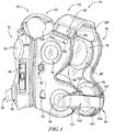
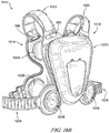
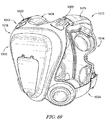
- a percussion therapy apparatus 10 is shown.
- the percussion therapy apparatus 10 illustratively includes a covering 12 having a chest panel 14 and a back panel 16, and percussive devices 18 that are attachable to the covering 12 to engage with the patient's torso to provide thoracic percussion therapy.
- the percussion therapy apparatus 10 illustratively includes an attachment assembly 20 comprising shoulder straps 22 and side strap assemblies 24 for securing the covering 12 to the patient's torso.
- the percussion therapy apparatus 10 is formed as a sleeveless garment, or vest, to be worn by the patient for receiving percussion therapy.
- the chest panel 14 and the back panel 16 are illustratively embodied include and adapt for curvature to conform generally to the form of a patient's torso. Properly fitting the percussion therapy apparatus 10 to the patient provides more efficient application of percussive therapy and reduces the negative effects to the patient.
- the percussion therapy apparatus 10 illustratively includes contact padding 26, 28 arranged inside of the chest and back panels 14, 16 as an interface between the respective panel 14, 16 and the patient's torso.
- the chest and back panels 14, 16 each illustratively includes openings 30 defined therethrough for receiving the percussive devices 18 for providing the percussive force to the patient.
- the contact padding 26, 28 is illustratively arranged between the percussive devices 18 and the patient's torso to provide comfort in application of the percussive force of the percussive devices 18.
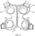
- the chest panel 14 illustratively includes a right section 32 and a left section 34 each respectively arranged on the right and left side of the patient's chest when the apparatus 10 is worn.
- the right and left sections 32, 34 illustratively form an hour glass-shape, each defining one half thereof and each generally having an outline that is a mirror image of the other.
- the right and left sections 32, 34 each illustratively include a straight edge 36 on a medial side thereof for releasably coupling to one another as explained herein.
- the right section 32 illustratively includes a user interface 38.
- the user interface 38 illustratively provides a communication interface for the user to operate the percussive devices 18 as described in more detail below.
- the left section 34 illustratively includes a break button 40 for user controlled impromptu pausing of the percussive operation of the percussive devices 18 during a percussion therapy cycle.
- the left section 34 illustratively includes a power port 42 for connection with a power cord to receive electric power for charging and/or operation.
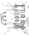
- the right section 32 of the chest panel 14 illustratively includes an inner pane 44, an outer pane 46, and a frame pane 48 arranged between the inner and outer panes 44, 46.
- Each of the panes 44, 46, 48 illustratively includes openings 30 defined therein to receive the percussive devices 18.
- the inner pane 44 illustratively includes a groove 50 defined in a front side 52 thereof.
- the groove 52 illustratively extends vertically with curvature to accept cabling 45 therein for positioning between the inner pane 44 and the frame pane 48.
- the groove 50 illustratively connects with a space 54 of the inner pane 44 located near the top end 56 thereof.
- the inner pane 44 illustratively includes a shoulder portion 58 extending from the top end 56 thereof for connection with the back panel 16.
- the shoulder portion 58 illustratively includes an attachment device 60 embodied as one portion of hook and unbreakable loop fasteners attached to a rear side 62 thereof for connection with the back panel 16.
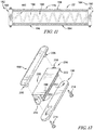
- the outer pane 46 illustratively includes a user interface mount 64 and percussion mounts 66 (comprising raised sections for ergonomics) and slider piping 67 for attachment on an outer surface 68 thereof as shown in Fig. 4 .
- the slider piping 67 illustratively receives complimentary slider receivers for attachment of accessories to the outer pane 46, for example but without limitation, an outer liner for protection and aesthetics.
- the user interface mount 64 illustratively includes a depression 70 formed in the outer surface 68 that receives a pendant 72 for coupling with the user interface 38 to the right section 32.
- the pendant 72 illustratively includes a number of arms 75 for releasably securing about the user interface 38.
- the pendant 72 illustratively extends through an opening 74 defined through the outer pane 46 and the depression 70 for attachment with the frame pane 48 as discussed below.
- the outer pane 46 illustratively includes the straight edge 36 formed on the medial side thereof.
- the straight edge 36 includes a zipper portion 76 of a zipper assembly 76, 78 attached thereto for releasable coupling between the right and left sections 32, 34.
- the zipper portion 76 illustratively includes a top end 80 and a bottom end 82 and is attached to the straight edge 36 along its entire length between its ends 80, 82.
- the zipper portion 76 is illustratively attached to the outer pane 46 and is angled between its top and bottom ends 80, 82 such that its bottom end 82 is positioned farther from the sagittal plane (of the patient when wearing the percussion therapy apparatus) than its top end 80.
- the zipper portion 76 is arranged at an angle ⁇ relative to the sagittal plane within the range of about 1 degree to about 5 degrees, for example but without limitation, about 1.8 degrees, or about 3 degrees.
- the frame pane 48 illustratively provides a substructure for the right section 32 as shown in Fig. 4 .
- the frame pane 48 is illustratively embodied as a sheet of material including rings 84 that define the openings 30 and a stem 86 extending between the rings 84.
- the frame pane 48 illustratively includes a side tab 90 extending from the (lower) ring 84 for connection with the respective side strap assembly 24.
- the left section 34 of the chest panel 14 illustratively includes an inner pane 92, an outer pane 94, and a frame pane 96 arranged between the inner and outer panes 92, 94.
- the panes 92, 94, 96 each illustratively include openings 30 defined therein to receive the percussive devices 18.
- the inner pane 92 illustratively includes a groove 98 defined in a front side 100 thereof.
- the groove 98 illustratively extends vertically with curvature to accept cabling 47 therein for positioning between the inner pane 92 and the frame pane 96.
- the groove 98 illustratively connects with a space 102 of the inner pane 92 located near the top end 56 thereof.
- the inner pane 92 illustratively includes a shoulder portion 58 extending from the top end 56 of the inner pane 92 for connection with the back panel 16.
- the shoulder portion 58 of the inner pane 92 illustratively includes an attachment device 60 embodied as one portion of hook and loop material attached to a rear side 62 thereof for connection with the back panel 16.
- the outer pane 94 illustratively includes the break button 40 for pausing operation of the percussive devices 18 and the power port 42 for connection with a power cord as shown in Fig. 5 .
- the break button 40 illustratively includes a button assembly 104 including an actuator button 106 and housing 108 for receiving the actuator button 106.
- a raised section 110 is disposed on the front side 112 of the outer pane 94 and defines a hole 114 therethrough for receiving the button assembly 104.
- the cabling 47 illustratively connects with the actuator button 106 to provide communication with the percussive devices 18.
- a user can depress the actuator button 106 to operate the break button 40 to pause operation of the percussive devices 18 to allow the patient to cough without experiencing the percussive force.
- the actuator button 106 is embodied as a linear actuator, but in some embodiments may be any suitable style of actuator to operate the break button 40 for pausing.
- the power port 42 illustratively includes a power terminal 116 housed within a port housing 118 for connecting a power cord to receive electric power to charge and/or operate the apparatus 10 as shown in Fig. 5 .
- the port housing 118 illustratively connects with the frame pane 96 through the outer pane 94 for structural support.
- the power terminal 116 is illustratively received within an interior of the port housing 118 and is embodied as a 5-pin connector accessible through an opening 120 in a lower face of the port housing 118.
- the power terminal 116 illustratively includes wiring 122 that extends from a rear side of the port housing 118 for connection with the cabling 47.
- the power terminal 116 may include an suitable type and/or arrangement of connector for receiving power for charging and/or operating the apparatus 10.
- the outer pane 94 illustratively includes slider piping 67 attached to the outer surface 112 thereof.
- the slider piping 67 illustratively receives complimentary slider receivers for attachment of accessories to the outer pane 94, for example but without limitation, an outer liner for protection and aesthetics.
- the outer pane 94 illustratively includes the straight edge 36 formed on a medial side thereof.
- the straight edge 36 includes a zipper portion 78 of a zipper assembly 76, 78 attached thereto for releasable coupling with the zipper portion 76 of the right section 32.
- the zipper portion 78 illustratively includes a top end 80 and a bottom end 82 and is attached to the straight edge 36 of the outer pane 94 along its entire length between its ends 80, 82.
- the zipper portion 78 is illustratively attached to the outer pane 94 and is angled between its top and bottom ends 80, 82 such that its bottom end 82 is positioned farther from the sagittal plane (of the patient when wearing the percussion therapy apparatus) than its top end 80, in the opposite direction of the zipper portion 76 of the right section 32.
- the zipper portion 78 is arranged at an angle ⁇ relative to the sagittal plane, in the opposite direction of the zipper portion 76 of the right section 32, within the range of about 1 degree to about 5 degrees, for example but without limitation, about 1.8 degrees, or about 3 degrees. Angling the zipper assembly 76, 78 as described provides a conforming fit to the patient upon coupling with the right section 32, reducing slack and improving engaging with the patient's torso.
- the frame pane 96 illustratively provides a substructure for the left section 34 as shown in Fig. 5 .
- the frame pane 96 is illustratively embodied as a sheet of material including rings 84 that define the openings 30 and a stem 86 extending between the rings 84.
- the frame pane 96 illustratively includes a side tab 90 extending from the (lower) ring 84 for connection with the side strap assembly 24.
- the inner panes 44, 92 and outer panes 46, 94 of each of the chest panel 14 and back panel 16, respectively, are formed of a relatively soft but firm material such as compression foam, and the frame panes 48, 96 are formed of a semi-rigid polymer that flexes more easily in certain directions to provide support to the panels 14, 16 while permitting snug contact of the percussive devices 18 with the patient's torso and generally allowing movement of the patient while wearing the percussive therapy apparatus 10.
- any number of suitable materials may be used for each of the panes 44, 46, 48, 92, 94, 96.
- the back panel 16 includes a single section having an interior side 124 for engagement with the patient's back and an exterior side 126 opposite the interior side 124.
- the back panel 16 illustratively includes shoulder portions 128 extending therefrom for connection with the chest panel 14.
- the back panel 16 on the exterior side 126, includes depressions 204 for connection of the shoulder straps 22 and a receiver 129 disposed for receiving a control pack for control and power of the percussive devices 18.
- the back panel 16 illustratively includes an inner pane 130, an outer pane 132, and a frame pane 134 arranged between the inner and outer panes 130, 132.
- Each of the panes 130, 132, 134 illustratively include openings 30 defined therein to receive the percussive devices 18.
- the outer pane 132 illustratively includes spaces 136 for receiving couplers 180 of the shoulder straps 22 (as discussed below), and grooves 138 extending between the spaces 136 and the openings 30 for receiving cabling 140 between the inner pane 130 and the frame pane 134.
- the outer pane 132 illustratively includes the receiver 129 comprising a ridge 131 extending outward and a rim 133 attached to the ridge 131 to provide a ledge 135 that faces radially outward to receive a cover of the control pack.
- the cover can illustratively extend over the ledge 135 to releasably affix the control pack thereto.
- the frame pane 134 provides a sub-structure for the back panel 16.
- the frame pane 134 is illustratively connected with each of a handle 142, the side strap assemblies 24, and a mounting bracket 144.
- the frame pane 134 is illustratively embodied as a sheet of material including rings 146 that define the openings 30 and a stem 148 extending between the rings 146.
- the frame pane 134 illustratively includes a side tab 152 extending from each (lower) ring 146 for connection with the respective side strap assembly 24 and a handle tab 154 extending from each (upper) ring 146 for connection with the handle 142.
- the handle 142 illustratively includes a strap body 156 and plates 158 pivotably attached at opposite ends of the strap body 156.
- the strap body 156 illustratively attaches to the center of each plate 158.
- the handle tabs 154 each illustratively includes a slot 160 extending therethrough to receive the handle 142.
- the plates 158 are each passed through a respective slot 160 and pivoted on the strap body 156 to prevent removal from the slots 160.
- the strap body 156 is thus coupled to the frame pane 134 through the slots 160 of the handle tabs 154 which can only pass through the slots 160 in certain (flat) orientation.
- the strap body 156 illustratively includes padding 162 disposed therein for comfortable handling. Upon supporting the apparatus 10 using the handle 142, the loading is generally directed to the frame pane 134 reducing stress concentration on the less rigid components.
- each side strap assembly 24 illustratively includes a cam buckle 151 attached to the respective side tab 152, a cam strap 153 coupled to the cam buckle 151, a D-ring 155 coupled to the cam strap 153 and having a hook arm 157, and a main strap 161 attached to the side tab 152 of the back panel 16 for coupling with the D-ring to secure the chest and back panels 14, 16 together with adjustable fit of the covering 12 to the patient's torso.
- the side tabs 152 extend from their respective rings 146 in opposite directions for connection with the respective side strap assembly 24.
- the main strap 161 of each side strap assembly 24 illustratively includes an end 164 attached to the respective side tab 152 of the frame pane 134 of the back panel 16.
- the main straps 161 illustratively extend from the respective side tab 152 of the frame pane 134 out from between the inner and outer panes 130, 132 to couple with the chest panel 14.
- the main straps 161 each illustratively includes a strap body 166 comprising sheets 168, 170 arranged to overlap each other and illustratively stitched together at seams 172.
- the seams 172 are illustratively arranged at spaced apart intervals to define loops 174 with open ends 149 between the seams 172.
- the loops 174 each illustratively comprise pockets for selectively receiving the hook arm 157 of the D-ring therethrough as shown in Fig. 8A .
- the sheet 170 wraps around the sheet 168 and is stitched to the sheet 168 on a side 178 of the main strap 161 opposite the loops 174 as best shown in Fig. 8B .
- the D-ring 155 illustratively includes a body 159 from which the hook arm 157 extends.
- the body 159 illustratively includes a slot 163 defined therein for receiving the cam strap 153.
- the cam strap 153 is illustratively threaded through the slot 163 to couple with the D-ring 155 and is attached at each of its ends 165 to the cam buckle 151.
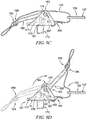
- the cam buckle 151 illustratively includes a base 167 and a cam lever 169 pivotably attached to the base 167 between a closed position (as shown in Figs. 9A and 9C , and in dashed line in Fig. 9D ) and an open position (as shown in solid line in Fig. 9D ).
- the base 167 illustratively includes a plate 171 having fastener mounts 173 extending therefrom for receiving fasteners (illustratively portions of connectors 180 discussed hereafter) to connect the base 167 to the respective side tab 152 as best shown in Figs. 9A-9C .
- the base 167 illustratively includes a pair of wings 175 extending from opposite ends of the plate 171 in a direction opposite to the fastener mounts 173. Each wing 175 illustratively includes a pivot hole 177 penetrating therethrough to receive a respective pivot arm 179 of the cam lever 169.
- the plate 171 illustratively includes a slot 187 defined therethrough for receiving connection of one end 165 the cam strap 153 and a stem 191 extends with resilience from the plate 171 for engagement with the cam lever 169 in the closed position.
- the cam lever 169 illustratively includes a body 181 formed as a plate having ergonomic curvature and the pair of pivot arms 179 that extend from opposite lateral sides of the body 181 near a pivot end 183 for rotatable connection within the pivot hole 177 of the respective wing 175.
- the body 181 illustratively includes a slot 189 defined therethough on an end opposite the pivot end 183 for connection of the other end 165 of the cam strap 153.
- a cam 185 extends along the body 181 near the pivot end 183 and protrudes from the body 181 in a direction perpendicular to the extension of the pivot arms 179. The cam 185 engages the plate 171 when the cam lever 169 is in the closed position to discourage unintended release from the closed position.
- the cam 185 illustratively contacts the stem 191 of the plate 171 of the base 167 in the closed position to maintain the closed position as shown in Fig. 9C .
- a user can remove the cam 185 from contact with the stem 191 of the base 167 by rotating the cam lever 169 from the closed position (broken line) and towards the open position (solid line).
- the stem 191 resiliently flexes under the force of the cam movement to allow the cam lever 169 to release from the closed position.
- Rotating the cam lever 169 out of the closed position moves the ends 165 of the cam strap 153 closer together releasing slack to the D-ring 155 for fit adjustment of the side strap assembly 24.
- Rotating the cam lever 169 into the closed position distances the ends 165 of the cam strap 153 from each other tightening the cam strap 153 and retracting the D-ring 155.
- a user can adjust the side strap assemblies 24 to fit the patient's torso.
- the cam lever 169 With the cam lever 169 in the open position, the user can insert the hook arm 157 of the D-ring into one of the loops 174 of the main strap 161 and rotate the cam lever 189 into the closed position. If the fit is correct, no further adjustment is necessary. If the fit is too lose or too tight, the user can place the cam lever 189 in the open position, place the hook arm 157 into a different loop 174 of the main strap 161, and return the cam lever 189 into the closed position, repeating as necessary.
- the cam strap 153 and main strap 161 are generally not stretchable, but some embodiments, at least one of the cam strap 153 and main strap 161 may include some limited elasticity to provide comfort in adjustment.
- the inner pane 130 illustratively includes shoulder portions 128 extending from a top end 56 thereof.
- the shoulder portions 128 each illustratively include an attachment device 60 (embodied as another portion of hook and loop material complimentary that of the shoulder portions 58 of the chest panel 14) attached to a rear side 62 thereof for connection with the chest panel 14.
- the shoulder portions 128 overlap with the shoulder portions 58 to fasten their attachment devices 60 together, illustratively as hook and loop joining.
- the attachment devices 60 may include any suitable fastening system.
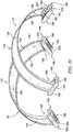
- the shoulder straps 22 extend between opposite ends 182, 184 thereof and define a cavity 186 therethrough for receiving cabling 188 for communication between the chest and back panels 14, 16.
- Each shoulder strap 22 illustratively includes a strap body 178 and couplers 180 disposed at each opposite end 182, 184 for attachment to the chest and rear panels 14, 16.
- Each strap body illustratively includes an upper sheet 190 and a lower sheet 192 attached together along seams 194 near their outer edges to create a portion of the cavity 186 therebetween.
- the shoulder straps 22 are illustratively formed of fabric and the couplers 180 are illustratively formed of plastic, but in some embodiments each may comprise any suitable materials.
- the cabling 188 illustratively extends through the cavity 186 in a serpentine arrangement to permit extension between the ends 182, 184 to relieve stress on the cabling 188 upon movement of the shoulder straps 22.
- the couplers 180 each includes an inner plate 196, an outer plate 198, and a connector 200 arranged between the inner and outer plates 196, 198.
- Each connector 200 is illustratively attached to the respective strap body 178 and is arranged with the spaces 54, 102, 136 of the respective inner pane 44, 130.
- the inner plate 196 is illustratively arranged in the depressions 202 formed in the outer surface 68, 112 of the right and left sections 32, 34 of the chest panel 14 and the depressions 204 formed in the back panel 16.
- the outer plate 198 illustratively includes mount fingers 206 that comprise fastener nuts (having internal threads) that extend through holes 208 in the respective depressions 202 for connection with the connector 200 and the inner plate 196 through fasteners holes 212.
- the inner plates 196 are illustratively arranged on the inner sides of the chest and back panels 14, 16 and extend through each of the respective inner panes 44, 92, 132 and the strap bodies 178 to connect with the outer plate 198 and connector 200 to clamp the strap bodies 178 and secure the straps 22 to the panel 14, 16.
- Fasteners 214 are inserted through the outer plates 198, back panel 16, and connectors 200, into connection with the mount fingers 206 as fastener nuts to attach the shoulder straps 22 to each of the chest and back panels 14, 16.
- the sandwiched attachment of the straps 22 to each of the chest and back panels 14, 16 distributes force broadly across the connections to reduce stress concentration.
- the connector 200 illustratively includes a body 216 including supports 218 disposed on opposite sides each having a fastener hole 212 therethrough for receiving fasteners 214 as shown in Fig. 12 .
- An extension plate 220 illustratively extends from a top side 222 of the body 216 between the supports 218 on an end near the connection with the outer plate 198 for attachment with the respective strap body 178.
- the body 216 illustratively extends between the inner and outer plates 196, 198 and defines another portion of the cavity 186 therethrough for passage of the cabling 188.
- the coupler 180 protects the cabling 188 against undesirable bending, crushing, and the like under movement of the straps 22.
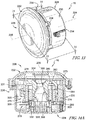
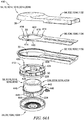
- the percussive device 18 includes an engagement end 224 for providing percussive force to the patient's torso and an outer end 226 opposite the engagement end 224.
- the percussive device 18 illustratively includes a housing 228 having a basin 230 and a cap 232 coupled to the basin 230.
- the housing 228 is illustratively cylindrical extending along an axis 235 between the engagement and outer ends 224, 226.
- the basin 230 is illustratively arranged near the engagement end 224 and includes a slot 234 for receiving an electrical connector 310 extending for connection with respective cabling 45, 47, 140.
- the cap 232 is illustratively arranged near the outer end 226 and is attached to the basin 230 with fasteners 236 to enclose the housing 228.
- a seal 231 is illustratively disposed between the connection of the basin 230 and the cap 232, embodied as an o-ring, to fluidly seal the housing 228 against incursion.
- the housing 228 is illustratively embodied to be formed of plastic, for example but without limitation, polycarbonate.
- Tthe fasteners 236 for joining the basin 230 and the cap 232 are illustratively plastic screws, for example but without limitation, Delta® fasteners as marketed by EJOT Gmbh & Co. Kg.
- the housing 228 and fasteners 236 may each me formed of any suitable materials.
- the percussive device 18 illustratively includes a percussion assembly 268 and an actuator 272 arranged for selective actuation of the percussion assembly 268 to provide percussive force.
- the percussion assembly 268 along with the actuator 272 is illustratively embodied as a voice coil, or voice coil linear motor, arranged within a cavity 270 of the housing 228.
- the percussion assembly 268 illustratively includes a percussion frame 274, a percussor 276 arranged for controlled movement to produce percussive force, and resilient members 278 for assisting movement of the percussor 276.
- the actuator 272 illustratively comprises an electromagnet selectively operable to drive movement of the percussor 276.
- the percussion assembly 268 selectively generates percussive force for application to the patient's torso through the housing 228.
- the percussor 276 illustratively includes a percussor body 280 defining an interior space 282, a magnet 284 arranged within the interior space 282, and a percussor cap 286 attached to the percussor body 280 to secure the magnet 284 within the interior space 282.
- the actuator 272 drives movement of the percussor 276 along the axis 235.
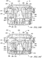
- the percussor 276 illustratively moves under force of the actuator 272 along the axis 235 between end positions as shown in Figs. 14B and 14C .
- the movement of the percussor 276 imposes percussive force that is transmitted through the percussion frame 274 to the housing 228 for application to the patient's torso.
- An illustrative example of an acceptable percussive force includes a force within the range of about 4 N to about 25 N. In some embodiments, the force may range from about 3 N to about 30 N.
- the percussive device 18 is generally cylindrical about the axis 235.
- the percussion frame 274 illustratively includes a base strut 288 extending about the axis 235 and anchors 290 connected to the base strut 288.
- the base strut 288 is illustratively embodied as an annular ring defining an inner void 292 therein for receiving the percussor 276.
- the anchors 290 are illustratively embodied as legs extending parallel with the axis 235 between opposite ends 294, 296 thereof.
- Each of the ends 294, 296 include fastener holes 298 defined therein for receiving fasteners for attachment of the resilient members 278.
- the anchors 290 are illustratively embodied as a set of three arranged with equal circumferential spacing around the axis 235, but in some embodiments, the anchors 290 may include any suitable number and/or arrangement to support the percussion assembly 268.
- the percussion frame 274 is illustratively formed by die-cast aluminum, but in some embodiments, may be formed of any suitable materials and/or process.
- the percussor cap 286 is illustratively embodied to have a ring shaped body 300 having and feet 303 extending axially from a side 302 the body 300 towards the outer end 226 for connection with one of the resilient members 278.
- Each foot 303 illustratively includes an alignment stub 305 extending axially therefrom for engagement with alignment notches 279 of one of the resilient members 278 (discussed below).
- the body 300 of the percussor cap 286 illustratively includes another side 304 opposite the side 302 for engagement with the percussor body 280 and an assembly stub 307 extending from the side 304 in an opposite direction from the alignment stubs 305 for engagement within an alignment groove 343 of the percussor body 280 as discussed below.
- the percussor cap 286 illustratively includes flanges 306 extending radially outward from the body 300 for a length and parallel to the axis for another length to form a corner 301.
- the flanges 306 illustratively wrap around the outside of the percussor body 280 (as best shown in Figs. 14A-14C ).
- the percussor cap 286 is illustratively formed by die-cast aluminum but in some embodiments may be formed of any suitable materials and/or process.
- the actuator 272 is illustratively embodied as an electromagnetic coil winding including leads 308 arranged for connection with the electrical connector 310.
- the actuator 272 illustratively creates magnetic field to move the percussor 276 by passing electric current through the coil.
- the actuator 272 may include any suitable actuation device for moving the percussor 276 to create percussive force.
- the magnet 284 is illustratively embodied to have a ring shape.
- the magnet 284 illustratively includes arc segments 312 arranged successively about the axis 235 and being radially magnetized (with respect to axis 235).
- the arc segments 312 are illustratively arranged to form the ring shape and are mounted within the interior space 282 of the percussor body 280.
- a non-limiting example of an appropriate magnet include N84 high temperature magnets.
- the percussor cap 286 illustratively abuts the magnet 284 along an axial end of each arc segment 312 to secure the magnet 284 within the interior space 282 of the percussor body 280 (as best shown in Figs. 14A-14C ).
- the resilient members 278 comprise plate springs forming a spiral shape.
- the resilient members 278 illustratively include a ring 314 formed about the axis 235 and having tabs 316 extending therefrom.
- the resilient members 278 illustratively include fingers 318 connected to the tabs 316 of the ring 314 and extending therefrom with curvature in the counter-clockwise direction (in the orientation shown in Fig. 15B ) to ends 319 thereof.
- the resilient members 278 illustratively include alignment notches 279 defined between the tabs 316 and inner attachment points 320 (discussed below).
- the fingers 318 have equal curvature to each other and define a close spacing with the next interior component (ring 314 and/or another finger 318) along its curved extension.
- the fingers 318 illustratively include inner attachment points 320 disposed near the connection with the tabs 316 of the ring 314 and outer attachment points 322 disposed near the ends 318.
- the inner attachment points 320 are illustratively arranged for connection with the percussor cap 286, namely with the feet 303.
- the outer attachment points 322 are illustratively arranged for connection with the percussion frame 274, namely with the ends 294, 296 of the anchors 290.
- the fingers 318 are illustratively flexible along their curvature between the inner and outer attachment points 320, 322 to extend axially to allow the ring 314 to move along with the percussor 276 and to assist movement back towards the opposite end position as shown in Figs. 14B and 14C .
- the reciprocation of the percussor 276 creates the percussive force with assistance from the resilient members 276.
- the inner and outer attachment points 320, 322 are embodied as fastener holes for receiving fasteners therethrough for attachment to their respective connections, but in some embodiments, the attachment points 320, 322 may include any suitable manner of attachment to their respective connections.
- the resilient members 278 are formed of 14310 steel by chemical etching, but in some embodiments, may be formed of any suitable material and/or any suitable process (for example, but without limitation, laser cutting and/or electroforming).
- the basin 230 of the housing 228 is illustratively embodied to have a cylindrical shape extending between an open end 324 for connection with the cap 232 and a closed end 326 opposite the open end 324.
- the basin 230 illustratively includes a circumferential wall 328 that extends about the axis 235 to define a portion of the cavity 270 of the housing 228 and an end wall 330 arranged at the closed end 326 to close the diameter of the circumferential wall 328 to enclose the cavity 270 within the basin 230.
- the basin 230 illustratively includes a mount wall 332 extending from the end wall 330 to a support end 334 to engage the actuator 272 (as best seen in Figs. 14A-14C ).
- the actuator 272 is secured to the mount wall 332 with adhesive, but in some embodiments may be secured in any suitable manner.
- the mount wall 332 is illustratively embodied to extend circumferentially about the axis 235.
- the mount wall 332 illustratively includes ribs 336 arranged circumferentially along the mount wall 332 in spaced apart relation to each other.
- the ribs 336 are illustratively embodied as enlarged sections for reinforcing the mount wall 332 to support the actuator 272.
- a buss duct 338 is illustratively formed in the basin 230 as shown in Fig. 15E .
- the buss duct 338 illustratively defines a space 340 therein to receive the connector 310 for connection with the cabling 45, 47, 140 to provide electrical communication with the actuator 272.
- the buss duct 338 illustratively extends axially along a portion of the circumferential wall 328, radially along the end wall 330, and axially along the mount wall 332 to provide the support end 334 to provide connection from outside the basin 230 to the actuator 272.
- the percussor body 280 is embodied to have a generally cylindrical shape formed about the axis 235.
- the percussor body 280 illustratively includes a circumferential wall 342 that extends about the axis 235 to define the interior space 282.
- the percussor body illustratively includes an open end 344 (as best shown in Fig. 15G ) and a closed end 346 that is at least partially closed by an end wall 348. As shown in Fig.
- an alignment groove 343 is defined in the circumferential wall 342 at the open at 344 complimentary to the assembly stub 307 of the percussor cap 286 for receiving the same for assembly alignment.
- the percussor body 280 is illustrative formed by high-speed turning operation and includes radial end stop surfaces 281 formed thereon.
- the percussor body 280 is illustratively formed with a balance of desirable weight and magnetic properties for creating percussive force for percussion therapy.
- the end wall 348 of the percussor body 280 illustratively includes an outer face 360.
- the outer face 360 illustratively includes attachment points 362 embodied as fastener holes for receiving fasteners therethrough for attachment of the inner attachment points 320 of one of the resilient members 278.
- the outer face 360 illustratively includes depressions 364 formed therein and ridge walls 366 extending axially from the outer face 360 and circumferentially about the axis 235 with circumferentially spaced apart arrangement for engagement with an inner diameter of the ring 314 of the resilient member 278.
- the percussor body 280 illustratively includes a hub 350 formed of a hub wall 351 that extends axially from the end wall 348 and circumferentially about the axis 235 within the interior space 282.
- the hub 350 and the end wall 348 collectively define a hub passage 352 that extends axially therethrough.
- the magnet 284 is positioned with the interior space 282 radially outside of the hub 248.
- the hub passage 352 is illustratively defined to include a sections 354, 355, 356, 358 defined by the interior of the hub wall 351.
- the sections 354, 355, 358 are illustratively have tapered diameters.
- the section 358 illustratively tapers inwardly from a larger diameter near an outer side of the end wall 348 to connect with the section 356 that illustratively has a constant diameter.
- the section 356 illustratively connects with the section 355 opposite the section 358.
- the section 355 illustratively tapers outwardly from the diameter of the section 356 and connects with the section 354.
- the section 354 illustratively tapers outwardly from the section 355 with a different angle of taper from the section 355 to an end of the hub 350 opposite the end wall 348.
- the percussive device 18 are illustratively arranged with their respective panels 14, 16 to form a isosceles trapezoidal shape on each of the patient's chest and back.
- the number of percussive devices 18 and their positioning is strategically selected.
- the position of the percussive devices 18 relative to the sternum and the spine should preferably not change significantly with patients ranging from the 5th percentile to the 95th percentile of bodily dimensions, and as such a single size of covering 12 can be used by a large portion of the patient demographic.
- the location of the percussive devices 18 may be locally adjustable relative to the respective panel 14, 16.
- the percussion therapy apparatus 1010 illustratively includes a covering 1012 having a chest panel 1014 and a back panel 1016, and percussive devices 1018 that are attachable to the covering 1012 to engage with the patient's torso to provide thoracic percussion therapy.
- the percussion therapy apparatus 1010 illustratively includes an attachment assembly 1020 comprising shoulder straps 1022 and side strap assembly 1024 for securing the covering 1012 to the patient's torso.
- the percussion therapy apparatus 1010 is similar to the percussion therapy apparatus 10 and is embodied include any of the features of the percussion therapy apparatus 10 except where conflicting with the specific description and illustration of the percussion therapy apparatus 1010.
- the percussion therapy apparatus 1010 is formed as a sleeveless garment, or vest, to be worn by the patient for receiving percussion therapy.
- the chest panel 1014 and back panel 1016 illustratively include curvature to conform generally to the form of a patient's torso. Properly fitting the percussion therapy apparatus 1010 can provide more efficient application of percussive therapy and reduce the negative effects to the patient.
- the percussion therapy apparatus 1010 illustratively includes contact padding 1026, 1028 arranged inside of the chest and back panels 1014, 1016 as an interface between the respective panel 1014, 1016 and the patient's torso.
- the contact padding 1026, 1028 is illustratively arranged between the percussive devices 1018 and the patient's torso to provide additional cushion in application of the percussive force of the percussive devices 1018.
- the chest panel 1014 illustratively includes a right section 1032 and a left section 1034 each respectively arranged on the right and left side of the patient's chest when the apparatus 1010 is worn.
- the right and left sections 1032, 1034 illustratively form an hour glass-shape, each defining one half thereof and each generally having an outline that is a mirror image of the other.
- the chest panel 1014 illustratively includes shoulder portions 1058 and side tabs 1090 for connection with the side straps assemblies 1024 of the attachment assembly 1020 to secure the apparatus 1010 to a patient's torso.
- the right and left sections 1032, 1034 each illustratively include a straight edge 1036 on a medial side thereof for releasably coupling to one another as explained herein.
- the right section 1032 illustratively includes the user interface 38 mounted thereto as shown in Fig. 17 .
- the user interface 38 illustratively provides a communication interface for the user to operate the percussive devices 1018 as described in more below.
- the left section 1034 illustratively includes the break button 40 for pausing operation of the percussive devices 1018 and the power port 42 for connection with a power cord to receive electric power.
- the right section 1032 of the chest panel 1014 illustratively includes an inner pane 1044, an outer pane 1046, and a frame pane 1048 arranged between the inner and outer panes 1044, 1046.
- Each of the panes 1044, 1046, 1048 illustratively include openings 1030 defined therein to receive the percussive devices 1018.
- the inner pane 1044 illustratively includes grooves 1050 defined in a front side 1052 thereof.
- the grooves 1050 illustratively extend vertically with curvature to accept cabling 1045 therein for positioning between the inner pane 1044 and the frame pane 1048.
- Retainer rings 464 are illustratively arranged within the openings 1030 of the inner pane 1044 for attachment of the contact padding 1026 as discussed below.
- the grooves 1050 illustratively connect with a space 1054 of the inner pane 1044 located near the top end 1056 thereof.
- the inner pane 1044 illustratively includes the shoulder portion 1058 extending from the top end 1056 thereof for connection with the back panel 1016.
- the shoulder portion 1058 illustratively includes an attachment device 60 embodied as one portion of hook and unbreakable loop fasteners attached to a rear side 1062 thereof for connection with the back panel 1016.
- the outer pane 1046 illustratively includes an interface mount 1064, percussion mounts 1066 (comprising raised sections for ergonomics), and snaps 1067 each attached to an outer surface 1068 thereof as shown in Fig. 19 .
- the snaps 1067 illustratively receive complimentary snap portions 1069 of accessories for attachment to the outer pane 1046, for example, an outer liner 1472 discussed herein.
- the interface mount 1064 illustratively includes a mount body 1070 including wings 1072 arranged on opposite lateral sides of the mount body 1070 with curvature to flexibly wrap (snap fit) around the user interface 38 for coupling to the chest panel 1014.
- the interface mount 1064 illustratively includes a mount plate 1065 for attaching to the mount body 1070 through a hole 1071 in the outer pane 1046 and for attaching to the inner pane 1048 to secure the interface mount 1064 to the chest panel 1014.
- the interface mount 1064 illustratively includes a mount base 1074 coupled to the chest panel 1014 and having a step 1076 for supporting the user interface 38 in attachment to the right section1032.
- the mount base 1074 illustratively attaches to the frame pane 1048 through a hole 1075 in each of the outer pane 1046 and includes a connection jack 1080 for receiving a connection end 1082 of cabling 1085 of the user interface 38 providing communication and power to and from the user interface 38.
- the mount base 1074 is illustratively connected to the power and control circuitry 1412 through the cabling 1045 to operate the percussion therapy apparatus as discussed below.
- the outer pane 1046 illustratively includes the straight edge 1036 formed on a medial side thereof.
- the straight edge 1036 includes a zipper portion 76 of a zipper assembly 76, 78 attached thereto for releasable coupling between the right and left sections 1032, 1034.
- the zipper portion 76 illustratively includes a top end 80 and a bottom end 82 and is attached to the straight edge 36 along its entire length between its ends 80, 82.
- the zipper portion 76 is illustratively attached to the outer pane 1046 and is angled between its top and bottom ends 80, 82 such that its bottom end 82 is positioned farther from the sagittal plane (of the patient when wearing the percussion therapy apparatus) than its top end 80.
- the zipper portion 76 is arranged at an angle ⁇ relative to the sagittal plane (indicated in broken line) within the range of about 1 degree to about 5 degrees, for example, about 1.8 degrees, or about 3 degrees.
- the frame pane 1048 illustratively provides a substructure for the right section 1032.
- the frame pane 1048 is illustratively embodied as a sheet of material including rings 1084 that define the openings 30 and a stem 1086 extending between the rings 1084.
- the frame pane 1048 illustratively includes a side tab 1090 extending from the (lower) ring 1084 for connection with the side strap assembly 1024.
- the left section 1034 of the chest panel 1014 illustratively includes an inner pane 1092, an outer pane 1094, and a frame pane 1096 arranged between the inner and outer panes 1092, 1094.
- Each of the panes 1092, 1094, 1096 illustratively include openings 1030 defined therein to receive the percussive devices 1018.
- the inner pane 1092 illustratively includes grooves 1098 defined in a front side 100 thereof.
- the grooves 1098 illustratively extends vertically with curvature to accept cabling 1047 therein for positioning between the inner pane 1092 and the frame pane 1096.
- the grooves 1098 illustratively connect with a space 1102 of the inner pane 1092 located near the top end 1056 thereof.
- the inner pane 1092 illustratively includes a shoulder portion 1058 extending from the top end 1056 of the inner pane 1092 for connection with the back panel 1016.
- the shoulder portion 1058 of the inner pane 1092 illustratively includes an attachment device 60 embodied as one portion of hook and unbreakable loop fasteners attached to a rear side 1062 thereof for connection with the back panel 1016.
- the outer pane 1094 illustratively includes the break button 40 for pausing operation of the percussive devices 18 and the power port 42 for connection with a power cord as shown in Fig. 20 .
- the break button 40 illustratively includes a button assembly 1104 having an actuator button 106 and housing 108 for receiving the actuator button 106.
- a raised section 1110 is disposed on the front side 1112 of the outer pane 1094 and defines a hole 1114 therethrough for receiving the button assembly 1104.
- the cabling 1047 illustratively connects with the actuator button 1106 to provide communication with the percussive devices 1018.
- a user can depress the actuator button 1106 to operate the break button 40 to pause operation of the percussive devices 1018.
- the actuator button 1106 is embodied as a linear actuation button, but in some embodiments may be any suitable style of actuator button to operate the break button 40 for pausing.
- the power port 42 illustratively includes a power terminal 116 housed within a port housing 118 as shown in Fig. 20 .
- the port housing 118 illustratively connects with the frame pane 1096 and is positioned with complimentary depressions 1097 of the inner and outer panes 1092, 1094.
- the power terminal 116 is illustratively received within an interior of the port housing 118 and is embodied as a 5-pin connector accessible through an opening 120 in a lower face of the port housing 118.
- the power terminal 116 illustratively includes wiring 122 that extends from a top side of the port housing 118 to a connector 125 for connection with the cabling 1047.
- the power terminal 116 may include an suitable type and/or arrangement of connector for receiving power for charging and/or operating the apparatus 10.
- the outer pane 1094 illustratively includes snaps 1067 on the outer surface 1112 thereof.
- the snaps 1067 illustratively receive complimentary snap portions 1069 of accessories for attachment to the outer pane 1046, for example, an outer liner 1472 discussed herein.
- the outer pane 1094 illustratively includes the straight edge 1036 formed on a medial side thereof.
- the straight edge 1036 includes a zipper portion 78 of a zipper assembly 76, 78 attached thereto for releasable coupling between the right and left sections 1032, 1034.
- the zipper portion 78 illustratively includes a top end 80 and a bottom end 82 and is attached to the straight edge 1036 of the outer pane 1094 along its entire length between its ends 80, 82.
- the zipper portion 78 is illustratively attached to the outer pane 1094 and angled between its top and bottom ends 80, 82 such that its bottom end 82 is positioned farther from the sagittal plane (of the patient when wearing the percussion therapy apparatus) than its top end 80, in the opposite direction of the zipper portion 76 of the right section 1032.
- the zipper portion 78 is arranged at an angle ⁇ relative to the sagittal plane, in the opposite direction of the zipper portion 76 of the right section 1032, within the range of about 1 degree to about 5 degrees, for example, 1.8 degrees, or 3 degrees. Angling the zipper assembly 76, 78 as described provides a conforming fit to the patient upon coupling with the right section 1032, reducing slack and improving engagement with the patient's torso.
- the frame pane 1096 illustratively provides a substructure for the left section 1034 as shown in Fig. 20 .
- the frame pane 1096 is illustratively embodied as a sheet of material including rings 1084 that define the openings 1030 and a stem 1086 extending between the rings 1084.
- the frame pane 1096 illustratively includes a side tab 1090 extending from the (lower) ring 1084 for connection with the side strap assembly 1024.
- the inner panes 1044, 1092 and outer panes 1046, 1094 of each of the chest panel 1014 and back panel 1016, respectively, are formed of a relatively soft but firm material such as compression foam, and the frame panes 1048, 1096 are formed of a semi-rigid polymer and are shaped to flex more easily in certain directions to provide support to the panels 1014, 1016 while permitting snug contact of the percussive devices 1018 with the patient's torso and generally allowing movement of the patient while wearing the percussive therapy apparatus 1010.
- any number of suitable materials may be used for each of the panes 1044, 1046, 1048, 1092, 1094, 1096.
- the back panel 1016 includes a single section having an interior side 1124 for engagement with the patient's back and an exterior side 1126 opposite the interior side 1124.
- the back panel 1016 illustratively includes a pack housing 1370 comprising an outer cover 1372 and a receiver 1374 of the back panel 1016 collectively defining a control cavity 1376 therein for housing a control pack 1378.
- the control pack 1378 illustratively provides power and control to the percussion therapy apparatus 1010 as discussed in more detail below.
- the back panel includes an inner pane 1130, an outer pane 1132, and a frame pane 1134 arranged between the inner and outer panes 1130, 1132.
- Each of the panes 1130, 1132, 1134 illustratively include openings 1030 defined therein to receive the percussive devices 1018.
- the inner pane 1130 illustratively includes spaces 1136 for receiving couplers 180 of the shoulder straps 1022, and grooves 1138 extending between the spaces 1136 and the openings 1030 thereof for receiving cabling 1140 between the inner pane 1130 and the frame pane 1134.
- the frame pane 1134 provides a sub-structure for the back panel 1016.
- the frame pane 1134 is illustratively connected with each of the handle 142, the side strap assemblies 24, and the control pack 1378.
- the frame pane 1134 is illustratively embodied as a sheet of material including rings 1146 that define the openings 30 and a stem 1148 extending between the rings 1146.
- the frame pane 1134 illustratively includes a side tab 1152 extending from each (lower) ring 1146 for connection with the respective side strap assembly 1024 and a handle tab 1154 attached to each (upper) ring 1146 for connection with the handle 142.
- the handle tabs 1154 each illustratively includes a slot 1160 extending therethrough to receive the handle 142.
- the plates 158 of the handle 142 are each passed through a respective slot 1160 and pivoted on the strap body 156 to prevent removal from the slots 1160.
- the strap body 156 is thus coupled to the frame pane 1134 through the slots 1160 of the handle tabs 1154 which can only pass through the slots 1160 in certain (flat) orientation.
- the loading is generally directed to the frame pane 1134.
- the side tabs 1152 extend from their respective rings 1146 in opposite directions for connection with the respective side strap assemblies 1024.
- the side strap assemblies 1024 are illustratively embodied to be similar to the side strap assemblies 24 discussed above and include all the features of side strap assemblies 24 unless contradicting the specific disclosure of side strap assemblies 1024.
- the end 164 of each respective main strap 161 of the side strap assembly 1024 is illustratively attached to the respective side tab 1152.
- the main straps 161 extend from the frame pane 1134 between the inner and outer panes 1130, 1132 to couple with the chest panel 1014 through the D-rings 155 and cam buckles 151 as described above.
- the inner pane 1130 of the back panel 1016 illustratively includes shoulder portions 1128 extending from a top end 1056 thereof.
- the shoulder portions 1128 each illustratively include an attachment device 60 (embodied as another portion of hook and unbreakable loop fasteners complimentary to that of the shoulder portions 1058 of the chest panel 1014) attached to a rear side 62 thereof for connection with the chest panel 1014.
- the back panel 1016 on the exterior side 1126, includes depressions 204 for connection of the shoulder straps 22 and a receiver 1129 disposed for receiving a control pack for control and power of the percussive devices 18.
- each shoulder portion 1128 overlaps with the respective shoulder portion 1058 to releasably fasten their attachment devices 60 together, illustratively as hook and unbreakable loop joining.
- the attachment devices 60 may include any suitable fastening system.
- the shoulder straps 1022 are attached with each of the chest and back panels 1014, 1016 with the shoulder portions 1058, 1128 arranged underneath for padding.
- the shoulder straps 22 extend between opposite ends 182, 184 thereof and define a cavity 186 therethrough for receiving cabling 188 for communication between the chest and back panels 14, 16.
- Each shoulder strap 1022 illustratively includes a strap body 178 and couplers 180 disposed at each opposite end 182, 184 for attachment to the chest and back panels 1014, 1016.
- Each strap body 178 illustratively includes an upper sheet 190 and a lower sheet 192 attached together along seams 194 near their outer edges to create a portion of the cavity 186.
- the shoulder straps 1022 are illustratively formed of fabric and the couplers 180 are illustratively formed of plastic, but in some embodiments each may comprise any suitable materials.
- the cabling 188 illustratively extends through the cavity 186 in a serpentine arrangement to relief stress on the cabling 188 upon movement of the shoulder straps 1022.
- the outer pane 1132 illustratively includes the receiver 1374.
- the receiver 1374 is illustratively similar to the receiver 129 and includes the ridge 131 extending outward and the rim 133 attached to the ridge 131 to provide the ledge 135 that faces radially outward to engage the outer cover 1372.
- the outer cover 1372 can illustratively extend over and cinch around the ledge 135 to releasably affix to the back panel 1016.
- the outer cover 1372 of the pack housing 1370 is shown in isolation from the receiver 1374.
- the outer cover 1372 illustratively forms a generally triangular-shaped outline and includes a body 1380 and a skirt 1382 attached to the body 1380 to secure the outer cover 1372 to the receiver 1374.
- the body 1380 is illustratively formed as a shallow foam dish having a central section 1384 extending generally flat (at least with little or limited curvature) in a plane and a transition section 1386 attached to and circumferentially surrounding the central section 1384 and curving away from the plane of the central section 1384 in a direction towards the receiver 1374 to form an outer edge 1388 of the body 1380.
- the central section 1384 illustratively includes an access door 1389 pivotably attached thereto for providing access to a power source 1402 discussed below.
- the skirt 1382 is illustratively attached to the outer edge 1388 of the body 1380.
- the skirt 1382 is illustratively attached to the outer edge 1388 about its entire length around the outer cover 1372 to form an annular shape having an axial edge 1389 attached to the outer edge 1388.
- the skirt 1382 is illustratively formed of a resilient fabric, for example, elastane, but in some embodiments may include any suitable material.
- the other axial edge 1390 of the skirt 1382 illustratively includes a stretch band 1392 attached thereto to elastically cinch the axial edge 1390 to a reduced radial size for attachment over the ledge 135 of the rim 133 of the receiver 1374.
- the stretch band 1392 extends along the entire axial edge 1390 of the skirt 1382, but in some embodiments, may extend along any suitable portion of the skirt to attach the outer cover 1372 to the receiver 1374.
- the skirt 1382 may cover the body 1380 including the central section 1384 while extending from the outer edge 1388 to its axial edge 1390.
- the generally sturdy but flexible construction of the outer cover 1372 and its elastic connection to the receiver 1374 provides the pack housing 1370 without overly restricting movement of the patient wearing the covering 1012.
- the skirt 1382 may be formed with resilient rigidity to form a snapfit with the receiver 1374.
- the outer cover 1372 illustratively defines a portion of the control cavity 1376 therein.
- the control pack 1378 is received at least partly within the portion of the control cavity 1376 defined by the outer cover 1372 with attachment points 1381, 1383 exposed for connection with the frame pane 1134 of the back panel 1016.
- the access door 1389 illustratively includes a triangular battery panel 1394 having two pivot arms 1396 extending from a top edge thereof for pivotably connection with the control pack 1378.
- the outer cover 1372 illustratively includes a space 1398 shaped complimentary to the access door 1389 to provide a continuous outer surface when the access door 1389 is closed.
- a portion of a battery cavity 1400 extends through the outer cover 1372 and the space 1398 to permit a power source, illustratively a battery 1402, to be inserted into the control pack 1378.
- control pack 1378 illustratively forms a power and control processing unit for operation of the percussion therapy apparatus 1010.
- the control pack 1378 illustratively includes a control casing 1404 having inner and outer sections 1406, 1408 attached to each other and collectively defining an interior space 1410 and a communications receptacle 1411.
- the control pack 1378 illustratively includes power and control circuitry 1412 arranged within the interior space 1410 for operation of the percussive devices 1018.
- the outer section 1408 of the control casing 1404 illustratively includes tabs 1413 for pivotable connection of the battery panel 1394 and a communications panel 1414 pivotably attached thereto for providing access to the communications receptacle 1411.
- the communications receptacle 1411 is adapted to house communications circuitry embodied as Bluetooth® circuitry arranged in communication with the circuitry 1412 to provide communication with other devices.
- the communications circuitry is illustratively adapted to provide communication between the power and control circuitry 1412 and other devices such as personal mobile devices (e.g., mobile phones, PDAs, tablet computers, etc.) and care facility devices (such as dedicated terminals, caretaker-assigned mobile devices, workflow systems, etc.).
- the communications circuitry may include any number and/or type of wireless communications circuitry, for example, Zigbee®, Wi-Fi®, WiMAX, 3G and/or 4G technology, radio frequency (RF), infrared (IR), sonar, including different versions thereof (e.g., classic Bluetooth® and Bluetooth 4.0/low energy). and/or wired communications circuitry, for example, parallel ports for any of standard 37 pin connections used by Hill-Rom Services, Inc., serial ports, coaxials, universal serial bus (USB), SPI, 12C, UART, fiber optics, ethernet, other general pin input/output (GPIO), other analogue and/or digital ports, etc.
- wireless communications circuitry for example, Zigbee®, Wi-Fi®, WiMAX, 3G and/or 4G technology, radio frequency (RF), infrared (IR), sonar, including different versions thereof (e.g., classic Bluetooth® and Bluetooth 4.0/low energy).
- wired communications circuitry for example, parallel ports for any of standard 37
- the communications circuitry may comprise a portion of the power and control circuitry 1412.
- the communications panel 1414 provides access to the communications circuitry and the power and control circuitry 1412 without requiring disassembly of the control pack 1378 to permit maintenance such as configuration, debugging, diagnosing, monitoring, customizing, and/or updating of control operations.
- the outer section 1408 illustratively includes a portion of the battery cavity 1400 defined there through for receiving the power source 1402.
- the inner section 1406 of the control casing 1404 illustratively includes a base wall 1416 and a side wall 1418 extending from the outer edge of the base wall 1416 and generally perpendicular to the base wall 1416 to define a portion of the interior space 1410.
- the base wall 1416 illustratively includes circuitry mounts 1422 extending from the base wall 1416 into the interior space 1410 for attachment of the power and control circuitry 1412 within the interior space 1410.
- the base wall 1416 illustratively includes tiered sections 1424, 1426, the tiered section 1426 being arranged closer to the outer section 1408 of the control casing 1404 than the tiered section 1426 as shown in Figs. 24 and 25 .
- the tiered section 1424 illustratively defines a portion of the battery cavity 1400 therethrough and includes a power connector 1428 for electrically connecting the battery with the power and control circuitry 1412 when the power source 1402 is received within the battery cavity 1400.
- the tiered section 1424 illustratively includes a section wall 1432 and a battery receptacle 1430 that defines the portion of the battery cavity 1400 provided by the base wall 1416.
- the battery receptacle 1430 illustratively includes a rear wall 1434 and side walls 1436 extending between the rear wall 1434 and the section wall 1432.
- the attachment points 1381, 1383 are illustratively attached to the rear wall 1434 of the base wall 1416 to connect with the frame pane 1134 of the back panel 1016.
- the attachment points 1381 and the frame pane 1134 each include fasteners holes 1438 for receiving fasteners to connect the control pack 1378 with the frame pane 1134.
- Each fastener hole 1438 of the frame pane 1134 is illustratively aligned with a corresponding fastener hole 1438 the attachment points 1381.
- the corresponding fasteners holes 1438 are illustratively arranged in a square pattern, but in some embodiments may be arranged in any suitable pattern.
- the attachment point 1383 is illustratively embodied as a cylinder extending axially from the base wall 1416 thorough an attachment hole 1385 defined through the frame pane 1134 (as best shown in Fig. 22 ) to be complimentary with the attachment point 1383.
- the attachment points 1381, 1383 and the fastener holes 1438 are illustratively centrally positioned with respect to the back panel 1016.
- the attachment points 1381, 1383 and the fastener holes 1438 illustratively form the only fixed connection of between the control pack 1378 and the back panel 1016.
- the control pack 1378 is illustratively rigid in comparison to the more forgiving compression foam of the chest and back panels 1014, 1016, the localized and centralized attachment between the control pack 1378 and the back panel 1016 provides ease of movement to the patient wearing the covering 1012 by permitting chest and back panels 1014, 1016 to flex while the control pack 1378 remains rigid to protect the circuitry within.
- the control pack 1378 can incur limited movement within the control cavity 1376 of the pack housing 1370 resultant from flexing of the panels 1014, 1016.
- control pack 1378 is illustratively formed of a rigid plastic, generally with a triangular shape having rounded corners, generally complimentary to the shape of the pack housing 1370.
- control pack 1378 may include any suitable materials and have any suitable shape for forming a power and control processing unit.
- another illustrative percussion therapy apparatus 2010 illustratively includes a covering 2012 for securing to a patient's torso having percussive devices 2018 coupled to the covering 2012 to provide high frequency percussive force to the patient to assist in expectoration.
- the percussion therapy apparatus 2010 illustratively includes a chest panel 2014 and a back panel 2016 each defining openings 2030 therethrough for receiving the percussive devices 2018 for attachment.
- the percussion therapy apparatus 2010 illustratively includes an attachment assembly 2020 including should straps 2022 and side strap assemblies 2024 to secure the covering 2012 to the patient's torso.
- the chest panel 2014 illustratively includes a right section 2032 and a left section 2034 (according to patient's right and left) each joined at a medial edge 2036 thereof.
- the right and left sections 2032, 2034 each illustratively include an adjustment knob 2050 of the respective side strap assembly 2024 for adjusting the effective length of the side strap assemblies 2024.
- the right and left sections 2032, 2034 each illustratively receive two percussive devices 2018 therethrough for engagement with the patient's torso to provide percussive force.
- the covering 2012 illustratively forms a generally continuous surface across the chest panel 2014.
- the chest panel 2014 illustratively includes an access panel 2025 attached to the right section 2032 and selectively attachable to the left section 2034 to enclose a user interface 38 as discussed in detail below.
- the back panel 2016 illustratively includes a power source 2042, illustratively embodied as a battery, received within a battery cavity 2400.
- the power source 2042 is illustratively connected to the power and control circuitry 1412 located within the covering 2012 to provide power and control to the percussive devices 2018.
- the chest panel 2014 is shown with the access panel 2025 opened.
- the chest panel 2014 illustratively includes a break button 2040 positioned on the upper percussive device 2018 of the left section 2034.
- a user can depress the break button 2040 to pause operation of the percussive devices 2018, for example, but without limitation, to cough and/or expectorate.
- the break button 2040 is similar to the break button 40, but is ergonomically positioned on the percussive device 2018 for ease of access, reduction in spatial requirements and structural components.
- the chest panel 2014 illustratively includes a depression 2060 formed therein collectively by portions of the right and left sections 2032, 2034 at the medial interface.
- the depression 2060 illustratively includes an interface receptacle 2062 for receiving the user interface 38 for storage.
- the interface receptacle 2062 is illustratively formed complimentary to the user interface 38 and its cabling 2084 to permit a user to store the user interface 38 within the interface receptacle 2062.
- the user interface 38 is posistionable within the interface receptacle 2062 and illustratively includes the cabling 2084 extending from a bottom end thereof and extending to a connector 2086 positioned within the interface receptacle 2062.
- the connector 2086 is illustratively in communication with the power and control circuitry 2412 to provide power and communication therebetween.
- a display 39 of the user interface 38 is illustratively arranged to face the chest panel 2014.
- the cabling 2084 is illustratively arranged to permit the user interface 38 to be removed from the interface receptacle 2062 and operated by a user.
- the user interface 38 is adapted to be operated by a patient wearing the covering 2012 and/or by another user.
- the cabling 2084 and display 39 are illustratively configured to allow a patient wearing the covering 2012 to bring the display 39 within viewing range (distance and angle) relative to the patient, for example, about 40 cm from the patient's eye and within an angle of about 0 to about 90 degrees from the horizontal relative to the patient's eye.
- the chest and back panels 2014, 2016 illustratively include similar construction to those of panels 14, 16, 1014, 1016 including inner and outer panes, and a frame pane 2048 disposed between the respective inner and outer panes.
- the frame pane 2048 of the chest panel 2014 illustratively includes right and left portions 2054, 2056 each defining openings 2030 for receiving the percussive devices 2018 therethrough.
- a retractable leash assembly 2070 of the side strap assemblies 2024 illustratively extends from each of the left and right portions 2054, 2056 for connection with the back panel 2016.
- each retractable leash assembly 2070 illustratively includes the adjustable knob 2050 having a ratcheting device therein, a leash 2072 connected to the knob 2050 and arranged for slack adjustment thereby, and a mooring 2074 attached to the back panel 2016 and having a track 2076 defined therethrough for receiving the leash 2072 slidingly threaded through the mooring 2074 to couple the leash 2072 with the back panel 2016.
- the knobs 2050 having their ratcheting devices are illustratively attached to their respective right and left portions 2054, 2056 (the knobs 2050 illustratively protrude through other panes of the chest panel 2014 as needed for access by users) as shown in Fig. 34 .
- the leash 2072 illustratively connects to the knob 2050 at a first end, loops through the mooring 2074, and connects to the knob 2050 also at its opposite end to form a continuous loop.
- the leash assembly 2070 illustratively includes additional moorings 2078 attached to the chest panel 2014 and receiving the leash 2072 through respective track 2076 therein for guiding the leash 2072 between the chest and back panels 2016.
- the ratcheting device of the knob 2050 is released by pulling outward on the knob 2050. Operation of the knob 2050 to retract or extend the length of the leash 2072 reduces or extends the allowable separation between the knob 2050 and the mooring 2074 enabling adjustment of the fit of the covering 2012 to the patient.
- the mooring 2074 is illustratively attached to the back panel 2016 with a main strap 2161a.
- the main straps 2161 illustratively extends between and connect at opposite ends with the mooring 2074 and the back panel 2016 to couple the chest and back panels 2014, 2016 together.
- the main straps 2161a are illustratively interchangeable with main straps 2161b, 2161c which have successively longer length as shown in Fig. 35B to accommodate differently sized patients.
- the moorings 2074 can be selectively attached to any of the main straps 2161a, 2161b, 2161c to accommodate interchange.
- the leash 2072 illustratively extends through a sock 2088 to shield the patient from contact with the leash 2072.
- the sock 2088 is illustratively connected to an end 2090 of the chest panel 2014 at one end and at an opposite end to the main strap 2161a near the mooring 2074.
- the sock 2088 illustratively defines an interior passage through which the leash 2072 is threaded.
- Fig. 37 shows the battery cavity 2400 is illustratively defined in the back panel 2016.
- the battery cavity 2400 is illustrative arranged generally centrally within the back panel 2016 between the percussive devices 2018 mounted to the back panel 2016 and is formed complimentary to the power source 2402.
- the power source 2402 illustratively includes an outer face 2404 which remains exposed when the power source 2402 is received within the battery cavity 2400 (as shown in Fig. 29 ).
- a storage housing 2406 is illustratively included in the back panel 2016.
- the storage housing 2406 illustratively comprises a receptacle 2408 and a cover 2410 that together forms a cavity 2414 for housing control and power circuitry for operation of the percussive therapy apparatus 2010.
- the storage housing 2406 is illustratively u-shaped and is arrange in close proximity to the battery cavity 2400 to provide ease of connection between the power source 2402 and the control and power circuitry.
- FIG. 39 another illustrative embodiment of a percussive device 3018 for use with the percussion therapy apparatuses 10, 1010, 2010 is shown with a portion of its housing 3228 removed.
- the percussive device 3018 illustratively includes a percussion assembly 3268 and an actuator 3272 (best shown in Fig. 39 ) arranged for selective actuation of the percussion assembly 3268.
- the percussion assembly 3268 along with the actuator 3272 is illustratively embodied as a voice coil, or voice coil linear motor.
- the percussion assembly 3268 illustratively includes a percussion frame 3274, a percussor 3276 arranged for controlled movement to produce percussive force, and resilient members 3278 for assisting movement of the percussor 3276.
- the actuator 3272 illustratively comprises an electromagnet selectively operable to drive movement of the percussor 3276.
- the percussion assembly 3268 selectively generates percussive force for application to the patient's torso through the housing 3228 (shown partially transparent in Fig. 40 ).
- the percussor 3276 illustratively includes a percussor body 3280 defining an interior space 3282, a magnet 3284 arranged within the interior space 3282, and a percussor cap 3286 attached to the percussor body 3280 to secure the magnet 3284 within the interior space 3282.
- the actuator 3272 drives movement of the percussor 3276 along the axis 3235.
- the percussor 3276 moves along axis 3235 between end positions as shown in Figs. 46A-46C .
- the movement of the percussor 3276 imposes percussive force that is transmitted through the percussion frame 3274 to the housing 3228 for application to the patient's torso.
- the percussor body 3280 is embodied to have a generally cylindrical shape formed about the axis 3235 including a basin 3230 and cap 3232 attached to the basin 3230 and collectively defining an cavity 3270 therein.
- the percussor body 3280 illustratively includes a circumferential wall 3342 that extends about the axis 3235 to define the interior space 3282 form an open end 3344 and a closed end 3346 that is at least partially closed by an end wall 3348 (as best shown in Fig. 43 ).
- the percussor body 3280 illustratively includes a hub 3350 formed of a hub wall 3351 the extends from the end wall 3348 circumferentially about the axis 3235 within the interior space 3282.
- the hub 3350 and the end wall 3348 collectively define a hub passage 3352 that extends axially therethrough.
- the magnet 3284 is positioned with the interior space 3282 radially outside of the hub 3350.
- the hub passage 3352 is illustratively defined to include a sections 3354, 3355, 3356, 3358 defined by the interior of the hub wall 3351 as shown in Fig. 40 .
- the sections 3354, 3358 illustratively have tapered diameters.
- the section 3358 illustratively tapers inwardly from a larger diameter near an outer side of the end wall 3348 to connect with the section 3356 that illustratively has a constant diameter.
- the section 3356 illustratively connects with the section 3355 opposite the section 3358.
- the section 3355 illustratively tapers outwardly from the diameter of the section 3356 and connects with the section 3354 that illustratively has a constant diameter.
- the percussive device 3018 illustratively includes a central shaft 3360 that extends between and connects to each of the basin 3230 and cap 3232 of the housing 3228.
- the central shaft 3360 illustratively extends through the hub passage 3248 engaging with the section 3356 of the hub passage 3248 as a bearing to guide the movement of the percussor 3276.
- the magnet 3284 is illustratively embodied to have a ring shape.
- the magnet 3284 illustratively includes arc segments 3312 arranged successively about the axis 3235 and being radially magnetized with respect to axis 3235.
- the arc segments 3312 are illustratively arranged to form the ring shape and are mounted within the interior space 3282 of the percussor body 3280.
- a non-limiting example of an appropriate magnet includes N84 high temperature magnets.
- the percussor cap 3286 illustratively abuts the magnet 3284 along an axial end of each arc segment 3312 to secure the magnet 3284 within the interior space 3282 of the percussor body 3280 (as best shown in Fig. 42 ).
- the resilient members 3278 are illustratively embodied as plate springs.
- the resilient members 3278 illustratively include coplanar hoops 3370, 3372, 3374, 3376.
- the hoops 3370, 3372, 3374, 3376 are illustratively arranged concentrically about the axis 3235 and with successively larger size from the innermost hoop 3370 to the outermost hoop 3376.
- Each of the hoops 3370, 3372, 3374, 3376 are closely spaced apart from immediately adjacent hoops 3370, 3372, 3374, 3376 but are connected thereto at connections points 3378, 3380.
- the (innermost) hoop 3370 is illustratively connected to the adjacent hoop 3372 at connection points 3378 which are positioned at 12 o'clock and 6 o'clock in the orientation of Fig. 43 .
- Hoop 3372 is illustratively connected to adjacent hoop 3374 at connection points 3380 which are positioned at 3 o'clock and 9 o'clock in the orientation of Fig. 43 .
- Hoop 3374 is illustratively connected to the adjacent (outermost) hoop 3376 at connection points 3378 which are positioned at 12 o'clock and 6 o'clock in the orientation of Fig. 43 .
- connection points 3378 are illustratively arranged angularly offset from the connection points 3380.
- the connection points 3378, 3380 between the same to hoops 3370, 3372, 3374, 3376 are arranged opposite each other.
- the disclosed arrangement of hoops 3370, 3372, 3374, 3376 and their connection points 3378 3380 permits the hoops 3370, 3372, 3374, 3376 to be resiliently displaced from each other along the axis 3235 as shown in Figs. 44 and 45 .
- the outermost hoop 3376 illustratively includes attachment holes 3382 formed therethrough on opposite sides for receiving fasteners for connection to the percussion frame 3274 (as best shown in Fig. 39 ).
- the innermost hoop 3370 illustratively includes attachment tabs 3384 extending radially therefrom and including attachment holes 3386 for receiving fasteners for connection to the percussor body 3280 (as best shown in Fig. 39 and 41 ).
- the resilient members 3278 assist movement of the percussor 3276 along the axis 3235.
- the percussive devices 3018 illustratively generate percussive force through the percussion assembly 3268 by movement of the percussor 3276 (including the percussor body 3280, magnet 3284, and percussor cap 3286) along the axis 3235.
- the percussor 3276 is illustratively shown as located in an elevated position (in the displayed orientation of Fig. 46A ) relative to the actuator 3272, shaft 3360, and housing 3228.
- the percussor 3276 is illustratively shown as located in a generally middle position (in the displayed orientation of Fig. 46B ) relative to the actuator 3272, the shaft 3360, and the housing 3228.
- the percussor 3276 is illustratively shown as located in a lowered position (in the displayed orientation of Fig. 46C ) relative to the actuator 3272, the shaft 3360, and the housing 3228. Reciprocation of the percussor 3276 between the elevated position and the lowered position as end positions produces the percussive force.
- the percussive devices 3018 are configured to operate to provide high frequency percussive force.
- the cap 3232 of the housing 3228 illustratively includes an end wall 3390 embodied as a plate and a circumferential wall 3392 extending from the end wall 3390 about the axis 3235.
- a mount wall 3394 extends from the end wall 3390 about the axis 3235 radially inward of the circumferential wall 3392 to a support end 3396 for supporting the actuator 3272.
- a stub 3398 illustratively extends axially from the end wall 3390 radially inward of the mount wall 3394.
- the stub 3398 illustratively includes a recess 3402 defined therein for receiving the shaft 3360.
- the cap 3232 is illustratively secured to the basin 3230 to define a cavity 3270 of the housing 3228.
- the basin 3230 illustratively includes a circumferential wall 3404 that extends about the axis 3235 and an end wall 3406 enclosing the circumferential wall 3404.
- the circumferential wall 3404 illustratively defines a rim 3400 opposite the end wall 3406 and extending about the axis 3235.
- the circumferential wall 3404 illustratively includes mounts 3408 extending radially from an exterior side 3410 thereof.
- the mounts 3408 illustratively extend axially along the exterior side 3410 between the rim 3400 and a flange 3412.
- the flange 3412 illustratively extends radially from the exterior side 3410 of the circumferential wall 3404.
- the rim 3400 engages with the cap 3232 to secure the housing 3228 and define the cavity 3270.
- FIG. 49 another illustrative embodiment of a percussive device 4018 for use in the percussion therapy apparatuses 10, 1010, 2010 is shown.
- the percussive device 4018 illustratively includes a housing 4228 defining a cavity 4270 therein and a percussion assembly 4268 arranged within the cavity 4270 to generate percussive force.
- the percussion assembly 4268 illustratively includes a percussor 4276 arranged for linear motion along the axis 4235 and an actuator 4272 for driving motion of the percussor 4276.
- the percussor 4276 illustratively comprises a magnet and the actuator 4272 comprises an coil-wound electromagnetic in electrical communication with a power source.
- the central shaft 4360 is illustratively orientated along the axis 4235 and extends through the actuator 4272 for guiding movement thereof.
- the shaft 4360 illustratively cantilevers from the actuator 4272.
- the percussor 4276 illustratively includes hardstops 4362 disposed on opposite axially ends and resilient member 4278 engaged with the hardstops 4362.
- the resilient members 4278 are illustratively embodied as linear springs each arranged in contact at one end with a respective hardstops 4362 and fixed relative to the housing 4228 at the other end.
- the resilient member 4278 arranged near the actuator 4272 is illustratively fixed at its other end to the actuator 4272 and the other resilient member 4278 is illustratively fixed at its other end to the cantilevered end of the shaft 4360.
- the end stops 4362 are illustratively circular shaped about the axis 4235.
- the end stops 4362 each illustratively include a base 4364 and a cylindrical tier 4366 that extends from the base 4364 to an end surface 4365 for engagement with other components at extreme ends of movement of the percussor 4276.
- the tier 4366 illustratively includes a cavity 4368 defined therethrough along the axis 4235 for receiving the respective resilient member 4278 and the base 4364 includes a hole 4370 defined therethrough along the axis 4235 for receiving the shaft 4360 and connecting with the cavity 4368.
- the tier 4366 illustratively includes an interior surface 4371 that defines the cavity 4368 having a slanted section 4372 extending from the end surface 4365 along the axis 4235 and a straight section 4374 extending from the slanted section 4372 along the axis 4235 to an interior portion 4376 of the base 4364.
- the interior portion 4376 of the base 4364 illustratively extends radially between the straight section 4374 and the hole 4370 for engaging an end of the respective resilient member 4278.
- the straight section 4374 illustratively engages sides of the respective resilient member 4278 to maintain its position along the axis 4235.
- the end stops 4362 are illustratively coupled to opposite ends of the percussor 4276 (magnet).
- the end stops 4362 illustratively receive the resilient members 4278 within their respective cavities 4368 to protect the resilient members 4278 during a bottom-out situation in which the end stops 4362 contact the housing 4228 or other components during actuation.
- the resilient members 4278 as linear springs may comprise conical springs as shown in Fig. 51 .
- graphical depictions of the movement of the percussor 4276 is shown as represented by position along the axis 4235 as a function of time.
- a generally sinusoidal wave form 4280 is created by the movement of the percussor 4276.
- the movement of the percussor 4276 between end positions A, B includes an acceleration region 4282 and a deceleration period 4284 as shown in Fig. 52 .
- the acceleration region 4282 includes all area between the end point A and a midpoint 4285 and the deceleration region 4284 includes all area between the midpoint 4285 and the end point B.
- the percussor 4276 accelerates from end point A to the midpoint 4285 and decelerates from the midpoint 4285 to the end point B.
- a non-sinusoidal waveform 4286 is created by movement of the percussor 4276 between the end positions A, B.
- the non-sinusoidal waveform 4286 illustratively includes acceleration regions 4290, 4292 and a deceleration region 4294, and illustratively defines zones 4296, 4298, 4300.
- the deceleration region 4294 illustratively extends along a shorter time interval than the deceleration region 4284 of the sinusoidal waveform 4280.
- the acceleration region 4290 includes the area between the end point A and the midpoint 4285, but also includes some of the area between the midpoint 4285 and the end point B.
- the acceleration region 4290 illustratively defines a ramping zone 4296 embodied between the end points A, B.
- the deceleration region 4294 illustratively includes the area between the ramping zone 4296 and the end point B.
- the acceleration region 4292 illustratively includes a portion of the area from the end point B to a midpoint 4287.
- the deceleration region 4294 and the acceleration region 4292 collectively define an impact zone 4298.
- the area between the impact zone 4298 and the proceeding end point A illustratively defines a power saving zone 4300.
- the ramping zone 4296 illustratively includes extended acceleration to maximize the force generated at end point B.
- the impact zone 4298 includes constant current to the actuator 4272 such that the movement of the percussor 4276 is through momentum alone, although in some embodiment some force from the actuator 4272 may be applied.
- the power saving zone 4300 is illustratively embodied as a zone of reduced power consumption represented by the area under the waveform 4286.
- the waveform 4286 is described based on operation of the percussive device 4018, but is equally applicable to the percussive devices 18, 1018, 2018, 3018 to maximize percussive force.
- the user interface 38 illustratively includes the display 39 and a number of buttons 41 for navigating the control operations shown on the display 39.
- the buttons 41 illustratively include a power button 368, a return button 370, directional buttons (up 372a, down 372b, left 372c, right 372d) 372, and a select button 374.
- the display 39 illustratively shows screens 5001-5170 and the buttons 41 can be depressed to interact with the screens 5001-5170 to operate the percussion therapy apparatuses 10, 1010, 2010 as discussed below.
- FIGs. 55-63 flow diagrams depict the operational sequences of the user interface 38.
- a manual operational sequence and preset therapy sequences are shown.
- Figs. 57A and 57B an adjustment sequence of the therapy sequences is shown.
- Figs. 58A-60C a device adjustment sequence is shown.
- Figs. 61A and 61B a service sequence is shown.
- Fig. 62 a battery status representation is shown.
- Fig. 63 a service tool sequence is shown.
- the user interface 38 is illustratively embodied to be in communication with the power and control circuitry 1412 to perform the disclosed operations.
- hardware and/or software for generating screens 5000-5170 (discussed below) on the display 39 of the user interface 38 is provided by the power and control circuitry 1412, but in some embodiments, operations user interface 38 may utilize any suitable arrangement of shared and/or dedicated software and/or hardware.
- a screen 5001 illustratively shows a splash screen indicating the "Monarch" product name and basic information such as total therapy hours and software specifications for a brief moment on startup, for example, 3 seconds before proceeding to screen 5002.
- Screen 5002 illustratively includes a number of options, shown as bars 5512, 5514, 5516, 5518.
- bar 5512 is currently active (indicating that depressing the select button 374 selects the active option 5512), as indicated by the expanded height of the bar 5512 compared to the other bars 5514, 5516, 5518.
- the bar 5512 is illustratively embodied as the Manual Sequence that permits direct (or “manual") manipulation of the percussion therapy apparatus operation.
- the Manual mode is embodied as an operation of the percussive devices 18, 1018, 2018, 3018, 4018 illustratively including a default 25 minute cycle duration illustrated by the stopwatch 376 on screen 5014.
- the stopwatch 376 illustratively includes a digital time display 376a and countdown bar 376b. Also illustratively shown on a top status bar 380 of screen 5014 is the screen title 382, a connectivity indicator 384, and a current battery life indicator 386.
- a user can illustratively depress the select button 374 to begin the Manual mode percussion therapy, which responsive begins operation of the percussive devices 18, 1018, 2018, 3018, 4018 and advances to screen 5015 as shown in Fig. 55 .
- the display 39 illustratively returns to screen 5012.
- Screen 5015 illustratively depicts the Manual mode having been operated for about 11 minutes and 13 seconds as indicated by both the time display and countdown bar.
- operation of the select button 374 illustratively pauses the Manual mode and advances to screen 5016 which starts a timer for the amount of time paused (illustratively shown as 1 minute 32 seconds).
- the display 39 automatically advances to screen 5017 to prompt a selection of either resume or stop (to end the Manual Sequence).
- a user can depress the up button 372a to respectively advance to screens 5011, 5012 to adjust the Manual mode.
- Depressing the down button 372b returns to the respective screen 5011, 5012.
- depressing the select button 374 advances to screen 5007 to adjust the Manual mode.
- a frequency parameter 388 is active (indicating that depressing the select button 374 selects the frequency parameter 388) as shown by the tab 390 which extends into the frequency parameter 388 and the up and down arrows shown above and below the current frequency parameter setting illustratively shown as 12 Hz.
- being active may be indicated by any visual distinction, for example but without limitation, color, font, form, etc.
- depressing up or down buttons 372a, 372b illustratively increases or decreases the value of the frequency parameter 388.
- depressing the right button 372d illustratively selects an intensity parameter 392 and advances to screen 5008.
- screen 5008 illustratively indicates that the intensity parameter 392 is active as illustrated by the tab 390 now being focused (extending) thereon.
- Selection of the intensity parameter 392 illustratively permits adjustment of the current intensity parameter value, shown as level 6, by using the up or down buttons 372a, 372b.
- Using the left or right buttons 372c, 372d illustratively toggles between screens 5007, 5009 respectively.
- screen 5009 illustratively indicates that a duration parameter 394 is active as the tab 390 has now been focused thereon.
- Selection of the duration parameter 394 illustratively permits adjustment of the current duration parameter setting, illustratively shown as 25 minutes, by using the up or down buttons 372a, 372b.
- Using the left button 372c illustratively returns to screen 5007.
- a user can illustratively stop the present therapy mode which returns to screen 5002, for example, on screen 5006.
- a user can illustratively operate the up and down buttons 372a, 372b to navigate between the bars 5512, 5514, 5516, 5518 (as shown in screens 5003, 5004, 5005 on Fig. 57A ).
- a user can illustratively navigate to bar 5514 as indicated by the expanded height of the bar 5514 on screen 5003 as compared to the other bars 5512, 5516, 5518.
- bar 5514 e.g., illustratively depressing the selection button while the bar 5514 is active
- a user can illustratively manipulate the Therapy mode 1 which advances to screen 5028 on Fig. 56 .
- user selection of bar 5514 illustratively advances to screen 5028 to permit manipulation of the predetermined initial parameters for the Therapy mode 1.
- a user can illustratively operate the user interface to start/stop, pause/resume, and adjust the current frequency, intensity, and duration parameters 388, 392, 394 in similar manner to that discussed above regarding the Manual mode.
- the Therapy mode 1 and the Therapy mode 2 each illustratively include up to eight distinct therapy intervals which can each have distinct values for any of the frequency, intensity, and/or duration parameters 388, 392, 394.
- an indictor 376c illustratively displays the current therapy interval as the first of eight (1/8).
- each therapy interval of the Therapy modes 1 and 2 can be individually manipulated for any of the frequency, intensity, and/or duration parameters 388, 392, 394 as discussed below.
- the stopwatch 376 illustratively displays the total time duration for all therapy intervals of the Therapy mode 1 and displays the current therapy interval (shown as 376c) and digital time display 376a within the countdown bar 376b.
- a user can begin the Therapy mode 1 and advance to screen 5029.
- the duration parameter 394 displayed on screens 5020-5022 and 5028-5032 illustratively shows the remaining duration of the therapy intervals (illustratively 3 minutes). Adjustment of the duration parameter 394 on screen 5022 illustratively sets the current duration parameter 394 for each therapy interval of the Therapy mode 1.
- user selection of the bar 5516 for the Therapy mode 2 illustratively performs the same behavior as Therapy mode 1 but according to its own predetermined initial settings. However, unlike the Manual mode, a user can illustratively select the bar 5518 to manipulate the predetermined initial parameters of each of the Therapy mode 1 and Therapy mode 2 to provide predetermined customized therapy regimes.
- a user can illustratively select the bar 5518 (Menu) to manipulate various therapy settings, device (percussion therapy apparatus 10, 1010, 2010) settings, to view device (percussion therapy apparatus 10, 1010, 2010) information, and/or to conduct service.
- Selection of the Menu (bar 5518) illustratively advances to screen 5034 ("menu screen" 5034), which presents the options 5520, 5522, 5524, 5526 respectively embodied as Therapy settings, Device Settings, Device Information, and Service.
- selection of Therapy Settings 5520 illustratively advances to screen 5035 which presents options 5528, 5530, 5532 respectively embodied as Edit Therapy 1, Edit Therapy 2, Isolate PODs (percussive devices 18, 1018, 2018, 3018, 4018).
- a user can illustratively toggle between the options 5528, 5530, 5532 as shown in screens 5035, 5045, 5053 using the up and down buttons 372a, 372b.
- Selection of Edit Therapy 1 5035 illustratively advances to screen 5036.
- screen 5036 illustratively displays as options for user selection a cough interval option 5534 (active), a cough duration option 5536 (inactive), and an eighth therapy interval option 5546 (inactive).
- the cough interval option 5534 is illustratively active as indicated by the bold script while the cough duration option 5536 and eighth therapy interval option 5546 are illustratively inactive as indicated in non-bold script.
- the cough interval option 5534 is illustratively embodied as a predetermined period of time between cough pauses in the operation of the percussive devices 18, 1018, 2018, 3018, 4018 (illustratively shown as 2 minutes on screen 5046) during the Therapy modes 1 and 2.
- the cough interval option 5534 is illustratively embodied as a predetermined duration of the cough pause in the operation of the percussive devices 18, 1018, 2018, 3018, 4018 (illustratively shown as 6 seconds on screen 5047) during the Therapy modes 1 and 2.
- the cough pauses are illustratively embodied as a controlled cessation of the movement of the percussor of the percussive devices by deactivation of the actuators to assist the patient in expectoration.
- the cough pauses are independent of any manual pause provided by activate of the break button 40.
- a user can alter the value of the cough interval option 5534 and the cough duration option 5536 respectively by operation of the up and down buttons 372a, 372b.
- depressing the down button 372b illustratively makes active a first therapy interval option 5538 and advances to screen 5038.
- a currently active therapy interval bar 398 is displayed on screen 5038 to identify the therapy interval (illustratively the first therapy interval option 5538 on screen 5038).
- depressing the down button 372b makes active a second therapy interval option 5540 and advances to screen 5039 on Fig. 57B .
- the second therapy interval option 5540 is illustratively active (as shown in bold script) and the currently active therapy interval bar 398 indicates the same by displaying "2/8".
- a third therapy interval option 5542 is illustratively shown on screen 5039 as inactive (as shown in non-bold script) and can be made active by depressing the down button 372b.
- an eighth therapy interval option 5546 is active (as shown in bold script) and a seven therapy interval option 5544 is inactive (as shown in non-bold script).
- the cough interval option 5534 is illustrative shown (inactive) beneath the either therapy interval option 5546 to illustrate that the list of options of (under) Edit Therapy 1 5528 are arranged in a continuous loop upon successive toggling either upward or downward such that additional pressing of the down button 372b (once) would return the display 39 to screen 5036.
- a user can depress the down button 372b to make active a "yes” option 5548 and advances to screen 5042.
- Selection of either the "yes” option 5548 or (the “no” option) respectively saves or does not save the settings as new parameters for execution of Therapy mode 1, and advances to screen 5040, momentarily displaying a message indicating whether the settings were saved or not.
- screen 5043 is displayed including a new therapy interval option 5550 as discussed below and the therapy interval option that is set to zero and all therapy interval option following are removed from the list on screens 5036-5040.
- saving the sixth therapy interval option with the value of the duration parameter 394 set to zero illustratively removes the sixth, seventh, and eighth therapy interval options from the list on screens 5036-5040 leaving only the first through fifth therapy interval options displayed.
- Screen 5043 thus, includes the list contents of screens 5036-5040 without those removed therapy interval options and with the new therapy interval option 5550.
- Screen 5043 can be toggled down (or up) to activation other list content and to advance to screen 5044 which illustratively shows a seventh interval option 5554 (active) and a sixth interval option 5552 (inactive).
- a new interval can be added and the sequence advances to screen 5052.
- Screen 5052 is illustratively embodied to add an additional (new) eighth therapy interval 5546a with values presently set to zero for all parameters 388, 392, 394.
- the values for parameters 388, 392, 394 of the (new) eighth therapy interval 5546a can illustratively be set and adjusted by similar operation to that shown and described for screens 5048-5051.
- selecting the eighth interval option 5546 advances to screen 5048 to permit manipulation of the parameters 388, 392, 394.
- the value of the frequency parameter 388 of the eighth interval option 5546 is selected (as shown by indicator 376c) and can be increased or decreased by toggling the up or down buttons 372a, 372b accordingly.
- depressing the right button 372d makes active the intensity parameter 392 of the eighth interval option 5546 and advances to screen 5049 to permit increase or decrease of the value thereof.
- depressing the right button 372d makes active the duration parameter 394 of the eighth interval option 5546 and advances to screen 5050 to permit increase or decrease (adjustment) of the value thereof.
- Adjustment of the value of the duration parameter 394 of the eighth interval option 5546 is illustratively shown by comparison of screen 5050 and screen 5051, respectively from a value of 3 minutes to 0 minutes (after each use of the down button 372b, the value drops by 1 minute).
- the adjustment of the frequency and intensity parameters 388, 392 can illustratively be performed similarly to that for the duration parameter 388 and thus is exemplified by the comparison of screens 5050, 5051.
- selecting an active one of any of the therapy interval options operates in a similar manner to screens 5048-5052 to permit adjustment of the values of the parameters 388, 392, 394.
- the Edit Therapy 2 option 5530 can be made active by navigating downward to advance to screen 5045.
- the Edit Therapy 2 option 5530 can be selected to permit adjustment of any of the cough interval option 5534, the cough duration option 5536, and the values of the parameters 388, 392, 394 of any of the therapy interval options, for the Therapy mode 2.
- the Therapy modes 1 and 2 provide independently customizable predetermined settings for operation of the percussive devices 18, 1018, 2018, 3018, 4018.
- the customizable predetermined settings create customized therapy regimes which can be arranged in advance and be made readily available without requiring specific programing with each therapy session. This can reduce the need for the patient to perform programming tasks and can provide direct caregiver involvement in preparing the apparatus for use without requiring the caregiver to be present during therapy sessions.
- the Isolate PODs option 5532 be made active by navigating downward to advance to screen 5053.
- selecting the Isolate PODs option 5532 illustratively advances to screen 5054 which displays a front diagram 5556 and back diagram 5558 each including POD markers 5560, 5562 representing the respective percussive devices 18, 1018, 2018, 3018, 4018 of chest and back panels in their relative positions.
- a first POD markers 5560a is active as shown in bold (front upper left POD marker corresponding to patients upper right chest), while second through fourth POD markers 5560b-5560d of the front diagram 5556 and first through forth POD markers 5562a-5562d of the back diagram 5558 are inactive as shown in non-bold.
- a user can make active the other (inactive) POD markers 5560b-d, 5062a-d by appropriate directional navigation, such as, for example but without limitation, depressing the right button 372d to make active the second POD marker 5560b and to advance to screen 5055.
- the second POD marker 5560b of the front diagram 5556 is active.
- toggling the directional buttons 372 makes active the other POD markers 5560, 5562.
- Illustratively selecting the second POD marker 5560b isolates the corresponding percussive device (illustratively, the percussive device proximate to the patient's upper left chest) and advances to screen 5056.
- a user can make active another POD marker 5560, 5562 by appropriate navigation and may isolate other POD markers 5560, 5562 as desired (as shown in Fig.
- a user can make active the device settings bar 5522 by depressing the down button 372b, advancing to screen 5059 as shown on Fig. 58A .
- Selecting the device setting bar 5522 illustratively advances to screen 5060 to display a device list 5564 including a wireless option 5564, a language option 5568, and a color themes option 5570 as shown in Fig. 58A .
- Selecting the wireless option 5564 illustratively advances to screen 5061 and presents a Bluetooth option 5572, Wi-Fi_33 option 5574, and LTE option 5576 each including a toggle switch 400 for each of Bluetooth, Wi-Fi_33, and LTE (4G) communications for selectively turning each communications protocol on or off.
- the user interface 38 is illustratively operable to permit operation and/or control of the percussion therapy apparatus 10, 1010, 2010 through a remote device, for example but without limitation, a smartphone, laptop, and/or tablet computer, and in such instance, the screens 5000-5170 are illustratively embodied to be presented on the remote device and including icons representing the buttons 41 for touch screen devices and compatible button operation for non-touch screen devices.
- selecting the Bluetooth option 5572 advances to screen 5062 and displays a devices list option 5578 and a status option 5580.
- Selection of the device list option 5578 illustratively advances to either screen 5063 or screen 5074 and presents a list of paired and other (unpaired) devices in range of the apparatus 10, 1010, 2010 and a scan devices option 5582. If upon selection of the Bluetooth option 5580, there exists a paired device (illustratively "FS901_0000006C”) which is already connected to the apparatus 10, 1010, 2010 advancement is to the screen 5074 which indicates the existing Bluetooth connection by the indicator dot 5584 as shown in Fig. 58A .
- selecting of the delete option 5588 terminates the paired state of that device which illustratively advances to screen 5083 for 2 seconds before advancing to screen 5084 which now does not show the device "FS901_0000006C". If instead, no existing connection exists, the advancement is to screen 5063 to accept requests for pairing.
- each of the devices from the list of paired and unpaired devices can be made active and can be selected by appropriate navigation, for example, toggling downward illustratively makes active the unpaired device "BLUESNAPSP-B76," and advances to screen 5064.
- selection of a paired device as illustrated by paired device "FS901_0000006C" advances to screen 5075 and permits selection of a connect option 5586 to initiate connection with the paired device and a delete option 5588 to initiate deletion of the paired device.
- toggling to the delete option 5588 advances to screen 5076 and permits selection of the delete option 5588 to terminate the paired state of that device which illustratively advances to screen 5083 for 2 seconds before advancing to screen 5084 which now does not show the device "FS901_0000006C".
- selection of the connect option 5586 illustratively connects the apparatus 10, 1010, 2010 with the paired device through Bluetooth connection and advances to screen 5074.
- BLUESNAPSP-B76 performs a pairing operation for that device and advances to screen 5085.
- screen 5085 a pairing code is provided for entry onto the device ("BLUESNAPSP-B76"). If the pairing code is improperly entered (or pairing fails for another reason), the screen advances to the appropriate one of screens 5079, 5080, 5081 for incorrect pairing code, incorrect serial number, and time out respectively, and on to screen 5084 with selection of the okay option 5590.
- the display 39 illustratively advances to screen 5085.1 and indicates that the device "BLUESNAPSP-B76" is now paired as indicated by the indicator dot 5584.
- screen 5085.1 a user can make active other devices by toggling, for example, to advance to screen 5085.2.
- a user can make active the scan devices option 5582 and advance to screen 5077.
- Selection of the scan devices option 5582 performs a Bluetooth scanning operation and advances to screen 5078.
- Screen 5078 illustratively shows a time bar (circle) 402 which decreases to show progress of the scanning operation, and displays information as to whether all or less than all devices were scanned before advancing to screen 5077.
- Screen 5078 illustratively includes a stop option 5592 for terminating the scan operation.
- a user can select one of the other (unpaired) devices, illustratively device "AGV-2725_IP", to advance to screen 5067 and display a pairing code for entry into the other device. Correct entry of the pairing code into the other device advances to the appropriate one of screens 5079, 5080, 5081. Because a device (“FS901_0000006C”) is already paired, confirmation of the correct pairing code advances to screen 5068 to confirm that the previously paired device (“FS901_0000006C”) should be replaced with the selected device (“AGV-2725_IP").
- toggling downward illustratively makes active the Wi-Fi option 5574 and advance to screen 5088.
- Selection of the Wi-Fi_33 option 5574 illustratively advances to screen 5089 and permits selection of an available networks option 5594, a settings option 5596, and a status option 5598.
- Section of the available network option 5594 illustratively prevents a list of networks 5600 for selection to connect thereto.
- the "NETWORK 1" is illustratively connected and toggling to other networks (e.g., "NETWORK 1 ... 6"; as shown in screens 5091-5093) illustratively permits selection of the same to perform a connection operation.
- a password can be entered as suggested in screens 5096, 5097-5106 in Figs. 59A-59C .
- Toggling to the bottom of the list 5600 illustratively permits selection of a search option 5602 for finding Wi-Fi_33 networks within range of the apparatus 10, 1010, 2010 as shown on screen 5094 in Fig. 59B .
- selection of the search option 5602 illustratively executes the search operation and advances to screen 5095 to indicate progress of the search operation and to present a stop option 5604 for terminating the search operation, the selection of which illustratively returns to screen 5090.
- toggling downward illustratively make active the settings option 5596 and advances to screen 5107 (as shown in Fig. 59D ).
- Selection of the settings option 5596 illustratively presents security list 5606 including Items 1, 2, 3
- Item 1 is currently set as indicated by the corresponding indicator dot 5608 being filled in while the indicator dots 5608 for Items 2 and 3 remain unfilled (inactive).
- toggling downward makes active Item 2 as indicated in bold script and advances to screen 5108.
- selection of Item 2 advances to screen 5117 and makes the corresponding indicator dot 5608 filled in while making the indicator dots 5608 of Items 1 and 3 unfilled.
- toggling upward makes active Item 1 and subsequent selection advances to screen 5108 as shown in Fig. 59D .
- toggling downward makes active Item 3 and advances to screen 5110.
- a number of security options 5610-5618 are available for each Item 1, 2, 3.
- toggling downward makes active an IP address option 5610 as indicated in bold script and advances to screen 5111.
- Item 1 remains selected as indicated by the indicator dot 5608 being filled in and selection of the active IP address option 5610 advances to screen 5118 to permit entry and/or alteration of the IP address value corresponding to Item 1.
- the currently entered IP address value for Item 1 is illustratively shown as 192.168.1.2.
- a user can illustratively alter the current IP address value for Item 1 into the text field 5620 by navigating text entry options 5622. Acceptance of the IP address value for Item 1 as entered is illustratively achieved by selection of the Okay option 5624 which stores the IP address of Item 1 and advances to screen 5111.
- toggling down makes active the subnet mask option 5612 and advances to screen 5112 as shown on Fig 59E .
- Item 1 remains selected as indicated by the indicator dot 5608 being filled in and selection of the subnet mask option 5612 advances to screen 5119 to permit entry and/or alteration of the subnet mask value for Item 1, illustratively shown as "255.255.240.0" within the text field 5620.
- the subnet mask value is illustratively entered and/or altered in similar manner to the IP address value using the text entry options 5622.
- toggling down makes active the DNS option 5614 and advances to screen 5113 as shown on Fig 59E .
- Item 1 remains selected as indicated by the indicator dot 5608 being filled in and selection of the DNS option 5614 advances to screen 5120 to permit entry and/or alteration of the DNS value for Item 1, illustratively shown as "10.13.1.33" within the text field 5620.
- the DNS value is illustratively entered and/or altered in similar manner to the IP address and subnet mask values using the text entry options 5622.
- toggling down makes active the Domain option 5616 and advances to screen 5114 as shown on Fig 59E .
- Item 1 remains selected as indicated by the indicator dot 5608 being filled in and selection of the Domain option 5616 advances to screen 5121 to permit entry and/or alteration of the Domain value for Item 1, illustratively shown as "HRC.CROP.ORG" within the text field 5620.
- the Domain value is illustratively entered and/or altered in similar manner to the IP address, subnet mask, and DNS values using the text entry options 5622.
- toggling down makes active the Client ID option 5618 and advances to screen 5114 as shown on Fig 59E .
- Item 1 remains selected as indicated by the indicator dot 5608 being filled in and selection of the Client ID option 5618 advances to screen 5121 to permit entry and/or alteration of the Client ID value for Item 1, illustratively shown as "1OP6W7" within the text field 5620.
- the Client ID value is illustratively entered and/or altered in similar manner to the IP address, subnet mask, DNS, and Domain values using the text entry options 5622.
- Wi-Fi_33 status information illustratively includes an indication of the applicable Wi-Fi_33 link speed, security/encryption type, the media access card (MAC) ID for the percussion therapy apparatus (Monarch), router/access point (AP), router/AP IP Address, router/AP MAC ID, but in some embodiments, may include any number and/or type of wireless communications information.
- MAC media access card
- toggling down illustratively makes active the LTE(4G) option and advances to screen 5125.
- the LTE(4G) option 5576 is active and the respective switch 400 is on.
- Selection of the LTE(4G) option 5576 advances to screen 5126 and presents various wireless information, for example but without limitation, a carrier name, an APN username, a mobile equipment identifier (MEID), and/or a sim card ID as shown in Fig. 59D .
- screen 5126 may include any number and/or type of wireless communications information.
- toggling downward makes active the language option and advances to screen 5127 (as shown on Fig. 60A ).
- selection of language option 5568 permits selection of the language for use on the display and advances to screen 5128 as shown in Fig. 60A .
- the language is currently set to English as indicated by indicator dot 5626 being filled in while the indicator dots 5626 corresponding to other languages (Duetsch, Espanol, Francias) are unfilled.
- the Duetsch language is active and other languages can be made active by appropriate toggling (as suggested on screens 5128-5135).
- the Spanish language is active and selection thereof illustratively changes the display language to Espanol and advances to screen 5131.
- the Spanish ("Espanol") language is active and selected and toggling upward makes active the English language and advances to screen 5132.
- selection of the English language changes the display language to English and advances to screen 5133 as shown in Fig. 60B .
- further downward toggling makes active the Spanish and French languages and advances to screens 5134 and 5135, in turn.
- toggling downward illustratively makes active the device information option 5524 and advances to screen 5142 as shown in Fig. 61A .
- Selection of the device information option 5524 illustratively presents a general option 5628, an errors option 5630, and a support option 5632.
- Selection of the general option 5628 illustratively present general device information and advances to screen 5144.
- General device information illustratively includes software revision no, total therapy hours, and FCC ID, but in some embodiments may include any number and/or type of general information about the apparatus 10, 1010, 2010.
- toggling downward makes active the errors option 5630 and advances to screen 5145 as shown in Fig. 60C .
- Fig. 60C on screen 5145 selection of the error option 5630 illustratively presents a list of errors 5634 and advances to screen 5146.
- the list of error 5634 is illustratively shown including the last 10 errors.
- a reset button 5636 is selectable to clear the list of errors 5634, the selection of which advances to screen 5149 for confirmation to clear the list of errors 5634.
- Confirmation to clear the list of error 5634 illustratively clears the list of errors 5634 and advances to screen 5151.
- a new list of errors 5638 preceding the list of errors 5634 is presented.
- the support option 5632 may include support instructions, support functions (e.g., diagnosis operations), and/or support request operations.
- toggling downward illustratively makes active the service option 5526.
- Selection of the service option 5526 prompts the user for a password for access and advances to screen 5155.
- a user can enter a password into the text field 5635 (illustratively shown on screen 5156) using the text entry options 5637 and can submit the entered password by selecting the Okay button 5639. If the submitted password is incorrect, a message is display as shown on screen 5161 in Fig. 61B . If the submitted password is correct, the service options 5640 are presented on screen 5157.
- the service options 5640 illustratively include a system reset option 5642, a set clock option 5644, a set date option 5646, and a service + option 5648.
- Selecting the system reset option 5642 advances to screen 5158 and presents a confirmation message.
- the user is prompted to confirm that system reset is desired by toggling appropriately to either yes or no as shown on screens 5158, 5159.
- Confirmation of system reset performs a system reset to default settings and advances to screen 5160.
- Screen 5160 illustratively presented a completion message and selection of the Okay button 5650 illustratively returns to screen 5157.
- appropriately toggling downward makes active either of the set clock option 5644 and the set date option 5646 and advances corresponding through screens 5162 and 5163.
- the top status bar 380 illustratively includes the battery life indicator 386 which communicates a battery status as shown on screens 5000A-5000A7.
- the battery life indicator 386 is shown as empty and includes an electrical symbol therein to indicate that charging is taking place.
- the screens 5000A2-5000A5 each indicate a corresponding amount of battery life, for example, about 75% to about 100% (screen 5000A2), about 50% to about 75% (screen 5000A3), about 25% to about 50% (screen 5000A4), and about 20% to about 25% (screen 5000A5), respectively.
- the top status bar 380 illustratively includes a Wi-Fi_33 indicator 402 to indicate that a Wi-Fi_33 connection is enabled.
- the top status bar 380 illustratively includes an LTE indicator 404 to indicate that an LTE connection is enabled.
- the presence of the indicators 384, 402, 404 indicate the specific connection type is enabled but not connected, however, upon connection the respective indicator illustratively changes color, illustratively from gray (enabled, not connected) to white (paired and/or connected).
- disabled, enabled (not connected), and connected wireless connectivity may be indicated by any suitable visual distinction.
- a number of service screens 5000E-5000E7 provide interaction when a service tool is connected to the power and control circuitry 1412. If a therapy session is operating, and a service tool is subsequently attached to the power and control circuitry 1412, on screen 5000E a warning message is shown indicating that the service tool cannot presently operate.
- screen 5000E1 is presented to request confirmation of connecting the service tool.
- a service password is requested on screen 5000E3.
- a user can enter a service password into the text field 5652 on screens 5000E3 and 5000E4 and submit for validation.
- active and/or selected is described as being indicated by one or more of allocating a tab, designated indicators, and/or bold script, but in some embodiments active and/or selected subject matter may be indicated by any visual distinction, for example but without limitation, color, font, form, etc.
- an attachment assembly 410 for securing the percussive devices 18, 1018, 2018, 3018, 4018 with the coverings 12, 1012, 2012 illustratively includes the panel 14, 16, 1014, 1016, 2014, 2016, a mounting bracket 412, the percussive device 18, 1018, 2018, 3018, 4018, and contact padding 26, 28, 1026, 1028.
- the mounting bracket 412 is rigidly attached to the panel 14, 16, 1014, 1016, 2014, 2016 and the percussive device 18, 1018, 2018, 3018, 4018 is secured to the mounting bracket 412.
- the panel 14, 16, 1014, 1016, 2014, 2016 illustratively includes the panes 92, 94, 96, 130, 132, 134, 1092, 1094, 1096, 1130, 1132, 1134 disclosed above.
- the frame pane 96, 134, 1096, 1134 illustratively includes a number of holes 414 for receiving stems 416 of the mounting bracket 412 for attachment therebetween.
- the holes 414 are illustratively formed on a ring 422 of the frame pane 96, 134, 1096, 1134 that defines the opening 30.
- the holes illustratively extend through the ring 422 between opposite surfaces 418, 420 thereof.
- the mounting bracket 412 illustratively includes a mount surface 424 and the stems 426 extend from the mount surface 424 for insertion within the holes 414 of the frame pane 96, 134, 1096, 1134 as shown in Fig. 64A .
- the stems 426 are each illustratively arranged complimentary to one of the holes 414 for reception therein.
- the mount surface 424 illustratively engages the surface 420 of the ring 422 of the frame pane 96, 134, 1096, 1134 through the inner pane 92, 130, 1092, 1130 and the stems 426 are inserted through the holes 414.
- the stems 426 receive fasteners from the opposite side of the frame pane 96, 134, 1096, 1134 to attach the mounting bracket 412 with the panel 14, 16, 1014, 1016, 2014, 2016.
- the percussive device 18, 1018, 2018, 3018, 4018 illustratively fastens to the mounting bracket 412.
- the percussive device 18, 1018, 2018, 3018, 4018 illustratively includes the housing 228, 2228, 3228, 4228 and wings 446 extending radially from the housing 228, 2228, 3228, 4228 for engagement with the mounting bracket 412 as shown in Fig. 64A .
- the wings 446 are illustratively arranged circumferentially about the housing 228, 2228, 3228, 4228 and each include a gap 448 defined therethrough for receiving a fastener.
- the mounting bracket 412 illustratively defines an opening 30 therethrough for receiving one of the percussive devices 18, 1018, 2018, 3018, 4018.
- the mounting bracket 412 illustratively includes wall 428 having an inner surface 430 that at least partially defines the opening 30.
- the wall 428 illustratively extends circumferentially about a central axis 432 to form fairings 434 having the inner surface 430 positioned at radial distance from the axis 432.
- the fairings 434 illustratively engage with the wings 446 of the percussive device 18, 1018, 2018, 3018, 4018 to secure the mounting bracket 412 with the percussive device 18, 1018, 2018, 3018, 4018.
- the wall 428 illustratively defines receptacles 436 located between adjacent fairings 434.
- the receptacles 436 are illustratively formed as sections of the wall 428 that have increased radial distance from the axis 432 relative to the inner surface 430 as shown in Figs. 64B and 64C .
- the receptacles 436 are illustratively arranged complimentary to the wings 446 of the percussive device 18, 1018, 2018, 3018, 4018 to receive the wings 446 therein.
- the fairings 434 each illustratively include a stopper surface 438 that faces axially towards the stems 426.
- the stopper surface 438 illustratively includes a rest section 440 positioned angularly offset from the adjacent receptacle 436 and a ramped section 442.
- the ramped section 442 illustratively has an incline along the axial direction and extends from the receptacle 436 to the rest section 440 with increasing proximity to the stems 426 to form a ramp between the adjacent receptacle 436 and the rest section 440.
- the percussive device 18, 1018, 2018, 3018, 4018 is inserted into the opening 30 of the mounting bracket 412 and rotated such that the wings 446 engage the stopper surface 438 to secure the percussive device 18, 1018, 2018, 3018, 4018 to the mounting bracket 412.
- the wings 434 are illustratively positioned within the receptacles 436 and a user can rotate the housing 228, 2228, 3228, 4228 to engage the wings 446 with the ramped sections 442 of the stopper surface 438. Under rotation, the wings 446 are wedged by the ramped sections 442 to the axial position of the rest section 440 and into a seated position in contact with the rest section 440.
- each wing 446 In the seated position, as shown in Fig. 64D , the gap 448 of each wing 446 is aligned with holes 450 of each of the wall 428 and the corresponding stem 426. Moreover, in the seated position, the gap 448 of each wing 446 is aligned with the corresponding holes 250 of the mounting bracket 412 to receive a fastener therethrough to prevent disengagement (untwisting) of the wings 446 and the fairings 434, and thereby securing the percussive device 18, 1018, 2018, 3018, 4018 with the mounting bracket 412.
- the contact padding 26, 28, 1026, 1028 illustratively attaches to the covering 12, 1012, 2012 over the percussive device 18, 1018, 2018, 3018, 4018 for interface with the patient's torso.
- the contact padding 26, 28, 1026, 1028 illustratively includes a contact side 452 for engagement with the patient's torso and a connection side 454 for attachment about the percussive device 18, 1018, 2018, 3018, 4018 to the covering 12, 1012, 2012.
- the contact padding 26, 28, 1026, 1028 illustratively comprises a soft but firm, resilient material (for example but without limitation, foam) for easing the imposition of percussive force of the percussive devices 18, 1018, 2018, 3018, 4018 onto the patient's body.
- a set of contact paddings 26, 28, 1026, 1028 having different firmness and/or other properties can be used to permit customizable cushioning, for example but without limitation, to apply less firm contact padding to a sensitive area of the patient's body.
- the contact padding 26, 28, 1026, 1028 illustratively defines a cavity 455 therein for receiving the engagement end 224 of the percussive device 18, 1018, 2018, 3018, 4018.
- the contact padding 26, 28, 1026, 1028 illustratively includes a head 456 arranged on the contact side 452 and a collar 458 extending from the head 456 on the connection side 454 for connection with the panel 14, 16, 1014, 1016, 2014, 2016.
- the collar 458 is illustratively embodied as a circular flange having an outer surface 460 and includes a groove 462 defined therein.
- the collar 458 illustratively engages the panel 14, 16, 1014, 1016, 2014, 2016 to secure itself about the percussive device 18, 1018, 2018, 3018, 4018.
- a retainer 464 is disposed within the opening 30 of the inner pane 92, 130, 1092, 1130 of the panel 14, 16, 1014, 1016, 2014, 2016 as shown in Fig. 65A .
- the retainer 464 is illustratively embodied as a ring that is attached to the frame pane 96, 134, 1096, 1134 and that defines an opening 30 for receiving the percussive device 18, 1018, 2018, 3018, 4018 therethrough.
- the retainer 464 illustratively engages with the collar 458 of the contact padding 26, 28, 1026, 1028 to secure the contact padding 26, 28, 1026, 1028 with the covering 12, 1012, 2012.
- the retainer 464 illustratively includes a base wall 466 and a frame wall 468 extending perpendicularly from a radially outer end the base wall 466.
- the frame wall 468 illustratively includes a number of tabs 470 extending radially inward from the frame wall 468 and spaced apart axially from the base wall 466.
- the tabs 470 are illustratively inserted into the groove 462 of the collar 458 of the contact padding 26, 28, 1026, 1028 to secure the collar 458 to the panel 14, 16, 1014, 1016, 2014, 2016 with snap-fit connection.
- a percussion therapy apparatus 1010 is shown with high resolution graphics and illustratively including appropriate curvature.
- the percussion therapy apparatus 1010 illustratively includes the outer liner 1472 attached to the covering 1012 to provide style, comfort, and protection.
- the outer liner 1472 is attached to the chest panel 1014 to protect the chest panel 1014 from foreign substances and to provide style and comfort to the outside of the covering 1012.
- the user interface 38 illustratively attaches to the covering 1012 outside of the outer liner 1472 while the break button 40 is operable from outside of the outer liner 1472.
- the percussion therapy apparatus 1010 is shown with the outer liner 1472 removed to reveal that the percussion therapy apparatus 1010 illustratively includes shoulder socks 1474 that wrap around the shoulder straps 1022 and shoulder portions 1058, 1128.
- the percussion therapy apparatus 1010 is shown with the outer liner 1472 removed as worn by a patient.
- the percussion therapy apparatus 1010 is shown in rear perspective view to show the pack housing 1370.
- the percussion therapy apparatus 1010 is shown in the rear perspective view as worn by a patient.
- the chest panel 1014 is shown from a rear (interior) view showing the contact padding 1026 covering the percussive devices 1018 on each of the right and left sections 1032, 1034.
- a power port 1040 is shown to illustratively protrude to the interior of the chest panel 1014.
- the back panel 1016 is shown from a front (interior) view showing the contact padding 1026 covering the percussive devices 1018.
- the percussion therapy device 1010 is shown in a front view with the outer liner 1472 attached to the chest panel 1014 and the outer cover 1372 attached to the back panel 1016.
- the percussion therapy device 1010 is shown in a rear view with the outer liner 1472 attached to the chest panel 1014 and the outer cover 1372 attached to the back panel 1016.
- the percussion therapy device 1010 is shown in a left side view with the outer liner 1472 attached to the chest panel 1014 and the outer cover 1372 attached to the back panel 1016.
- Fig. 73 the percussion therapy device 1010 is shown in a front view with the outer liner 1472 attached to the chest panel 1014 and the outer cover 1372 attached to the back panel 1016.
- the percussion therapy device 1010 is shown in a rear view with the outer liner 1472 attached to the chest panel 1014 and the outer cover 1372 attached to the back panel 1016.
- the percussion therapy device 1010 is shown in a left side view with the outer liner 1472 attached to the chest panel 10
- the percussion therapy device 1010 is shown in a right side view with the outer liner 1472 attached to the chest panel 1014 and the outer cover 1372 attached to the back panel 1016.
- the percussion therapy device 1010 is shown in a top view with the outer liner 1472 attached to the chest panel 1014 and the outer cover 1372 attached to the back panel 1016.
- the percussion therapy device 1010 is shown in a bottom view with the outer liner 1472 attached to the chest panel 1014 and the outer cover 1372 attached to the back panel 1016.
- the percussion therapy device 1010 is shown in a front view without the outer liner 1472 and without the outer cover 1372.
- the percussion therapy device 1010 is shown in a rear view without the outer liner 1472 and without the outer cover 1372.
- the percussion therapy device 1010 is shown in a left side view without the outer liner 1472 and without the outer cover 1372.
- the percussion therapy device 1010 is shown in a right side view without the outer liner 1472 and without the outer cover 1372.
- the percussion therapy device 1010 is shown in a top view without the outer liner 1472 and without the outer cover 1372.
- the percussion therapy device 1010 is shown in a bottom view without the outer liner 1472 and without the outer cover 1372.
- the outer liner 1472 illustratively includes a right section 1476 and a left section 1478 respectively attachable to the right and left sections 1032, 1034 of the chest panel 1014.
- Each of the right and left sections 1476, 1478 illustratively include a panel section 1480 formed complimentary to the respective right and left sections 1032, 1034 of the chest panel 1014, a connection strap 1482 for securing to a portion of the respective left and right sections 1032, 1034, and a shoulder section 1484 for covering at least a portion of the shoulder straps 1022.
- the outer liner 1472 illustratively provide a protective covering to keep the chest panel 1014 clean from foreign substances, for example but without limitation medication from a nebulizer and/or expectorant mucous.
- the outer liner 1472 illustratively provides a removable substrate for customizable graphic design for pleasing visual and/or texture profiles.
- the right section 1476 illustratively includes a set of holes 1486 for extension of the interface mount 1064 and cabling 1085 therethrough for mounting of the user interface 38.
- Each of the right and left sections 1476, 1478 illustratively include snap portions 1069 for engagement with the snaps 1067 of the chest panel 1014 to secure the outer liner 1472 thereto.
- a number of snap portions 1069 are positioned near the medial intersection of the right and left sections 1476, 1478 respectively at the top, middle, and bottom of the panel section 1480 of each of the right and left sections 1476, 1478.
- a snap portion 1069 is illustratively positioned on the connection strap 1482 of each of the right and left sections 1476, 1478.
- each of the left and right sections 1476, 1478 include a stretchable binding 1488 disposed on an outer edge thereof.
- the stretchable binding 1488 illustratively provides a resilient edging for easy securing of the outer liner 1472 to the covering 1012 with close fit.
- the panel section 1480 of the right and left sections 1476, 1478 illustratively includes side leashes 1490, 1492 at lower sides corresponding to the location of the side straps assemblies 1024.
- the side leashes 1490, 1492 illustratively comprise complimentary hook and unbreakable loop portions for releasably securing to each other around the respective side strap assembly 1024.
- the shoulder section 1484 illustratively include hook and 60able loop portions 1489 positioned at outer ends thereof for securing to the shoulder socks 1474.
- the shoulder socks 1474 each illustratively include complimentary hook and unbreakable loop fasteners 1494 for wrapping and securing around the shoulder straps 1022 and shoulder portions 1058, 1128.
- Each shoulder sock 1474 illustratively has a rectangular shape and is formed of fabric, and has an inner side 1496 and an outer side 1498.
- One of the complimentary hook and unbreakable loop fasteners 1494 is illustratively positioned on each of the inner and outer side 1496, 1498 at opposite ends 1500 of the shoulder sock 1474 such that wrapping and overlapping the opposite ends 1500 arranges the complimentary unbreakable loop fasteners 1494 into engagement with each other for releasable fastening.
- the shoulder socks 1474 each illustratively include hook and unbreakable loop fasteners portions 1502 for engagement with respective complimentary hook and unbreakable loop fasteners portions 1489 of the outer liner 1472.
- the shoulder socks 1474 each illustratively include a shoulder pad 1504 positioned beneath the shoulder straps 1022 and shoulder portions 1058, 1128 as the shoulder socks 1474 are secured thereon.
- the shoulder pad 1504 illustratively includes a padding 1506, illustratively formed of viscoelastic foam, enclosed within a pad housing 1508, embodied as fabric.
- the percussive devices 18 comprise magnets which move with the percussors and stationary actuators, but in some embodiments may include moving actuators and stationary magnets.
- the cabling 45, 47, 140, 188, 1045, 1047, 1085, 1140, 2084 illustratively provides electrical communications between the power and control circuitry 1412 and each of the respective percussive devices 18, 1018, 2018, 3018, 4018, the user interface 38, and the break button 40, 2040.
- the cabling 45, 47, 140, 188, 1045, 1047, 1085, 1140, 2084 as mentioned herein is distinguished numerically but in some embodiments each numerical designation may comprise some or all of the same cables and/or interconnected wiring as that of differently enumerated cabling.
- Disclosed hardware and/or software for computational communications and electrical power includes any style, number, and/or arrangement for performing the disclosed process.
- the percussive devices disclosed herein can be applied without attachment to the coverings in a hand-held fashion and may be equipped with local battery power and/or power cable.
- user interface 38 of percussion therapy apparatuses 10, 1010, 2010 stores one or more music files that are playable through the respective percussive devices 18, 1018, 2018, 3018, 4018, which comprise voice coils in some embodiments. Such music files are played, under the user's selective control, when devices 18, 1018, 2018, 3018, 4018 are not being used to perform percussion therapy, for example.
- user interface 38 includes volume controls, song selection controls, forward and reverse controls, pause controls, start and stop controls, and so forth.
- one or more other electronic devices link with the circuitry of apparatuses 10, 1010, 2010 to play music files through devices 18, 1018, 2018, 3018, 4018.
- Such other electronic devices link wirelessly with the circuitry of apparatuses 10, 1010, 2010 in some embodiments. Alternatively or additionally, such other electronic devices link with the circuitry of apparatuses 10, 1010, 2010 via a wired connection.
- the other electronic devices include, for example, smart phones, an iPods, tablet computers, smart watches, and MP3 players, just to name a few.
Landscapes
- Health & Medical Sciences (AREA)
- Epidemiology (AREA)
- Pain & Pain Management (AREA)
- Physical Education & Sports Medicine (AREA)
- Rehabilitation Therapy (AREA)
- Life Sciences & Earth Sciences (AREA)
- Animal Behavior & Ethology (AREA)
- General Health & Medical Sciences (AREA)
- Public Health (AREA)
- Veterinary Medicine (AREA)
- Dermatology (AREA)
- Percussion Or Vibration Massage (AREA)
Abstract
Description
- The present disclosure relates to devices, systems, and methods for percussion therapy. More specifically, the present disclosure relates to devices, systems, and methods for percussion therapy for a patient's torso.
- Patient respiratory systems can experience build-up of phlegm, mucous, and similar substances. Typically, healthy patients can expectorate such build-ups naturally. Certain respiratory ailments and other conditions affecting respiratory function can create excessive build-up and/or make expectoration more difficult. Chronic suffers of excessive build-up and/or reduced expectoration ability, such as, for example, those with cystic fibrosis, may require assistance to remove such build-up.
- Percussive therapy can assist in dislodging mucous and other build up from respiratory systems. However, proper manual percussive therapy generally requires a trained practitioner to perform the therapy on the patient. Moreover, manual percussive therapy can be time consuming and physically demanding for the practitioner, as well as uncomfortable and ineffective for the patient-recipient.
- The present application discloses one or more of the following features alone or in any combination.
- According to an aspect of the disclosure, a percussion therapy apparatus for thoracic percussion therapy may include a torso covering for securing to a patient's torso, the torso covering including a front panel having an interior side for engaging the patient's chest and a rear panel having an interior side for engaging the patient's back, a number of percussive devices coupled to the torso covering to provide percussive force to the patient's torso, and an attachment assembly for supporting the torso covering, the attachment assembly including a number of straps each having a first end connected to one of the front and the rear panels and a second end connected to the other of the front and the rear panels, at least one of the number of straps defines a cavity therein that extends between the respective first and second ends for receiving at least one cable therethrough to electrically communicate between the front and rear panels of the torso covering.
- In some embodiments, the front panel of the torso covering may include a first section and a second section releasably coupled to each other at a medial intersection.
- In some embodiments, the first and second sections may be releasably coupled at the medial intersection by a zipper assembly having first and second zipper portions attached to the first and second sections, respectively, the first and second zipper portions each having a top end and bottom end and each being angled between its respective top and bottom ends within the range of about 1 to about 5 degrees from the sagittal plane in opposite lateral directions.
- In some embodiments, the percussion therapy apparatus may further include a user interface configured to receive user input for adjusting percussive force of the percussive devices and a power source for providing power to the percussive devices, the control interface being releasably coupled to the front panel and the power source being releasably coupled to the rear panel.
- In some embodiments, adjusting the percussive force includes at least one of adjusting an intensity of percussive force, a frequency of percussive force, and a duration of a percussion cycle.
- In some embodiments, the percussion therapy apparatus may further include a break button for pausing a percussion cycle of the number of percussive devices. In some embodiments, the break button may be coupled to the front panel and in communication with the number of percussive devices.
- In some embodiments, the number of straps ay include a number of shoulder straps for arrangement over a patient's shoulders in a direction from back to chest and the attachment assembly may include a number of side straps each having a first end connected to one of the front and the rear panels and a second end connected to the other of the front and the rear panels and disposed on opposite lateral sides of the torso covering.
- In some embodiments, the front panel may include an inner pane, an outer pane, and a frame pane disposed between the inner and outer panes, at least one of the inner, outer, and frame panes including a groove defined therein for receiving cabling between adjacent panes. In some embodiments, the inner and outer panes may include compression foam and the frame pane may include semi-rigid plastic.
- In some embodiments, the rear panel may include an inner pane, an outer pane, and a frame pane disposed between the inner and outer panes. In some embodiments, the inner and outer pane comprise a compression foam and the frame pane comprises a semi-rigid plastic.
- In some embodiments, at least one of the inner, outer, and frame panes including a groove defined therein for receiving cabling between adjacent panes.
- In some embodiments, the apparatus may include a control pack coupled with the rear panel to provide power and communication to the percussive devices.
- In some embodiments, the control pack may be coupled with the rear panel at location near a center of the control pack and a center of the rear panel.
- In some embodiments, the control pack may be attached to the frame pane through an opening in the outer pane.
- In some embodiments, the rear panel may include a receiver assembly for housing the control pack, and the receiver assembly may include a flange extending along an exterior side of the rear panel to define a receiver space and receiver trim connected with the flange and defining a lip.
- In some embodiments, the receiver assembly may include a pack cover configured to engage with the lip of the receiver trim to couple the pack cover with the rear panel and enclose the receiver space.
- In some embodiments, the lip may include at least two outwardly extending sections and the outer cover includes a skirt adapted to extend over the at least two outwardly extending sections and to cinch about the lip to secure the pack cover thereto.
- In some embodiments, the rear panel may include a number of openings defined therethrough for receiving the percussive devices to provide percussive force to the patient's back. In some embodiments, the number of openings may include four openings arranged in a trapezoidal shape.
- In some embodiments, the number of percussive devices may each include a housing defining a cavity therein, a percussion assembly arranged within the cavity to produce percussive force, and an actuator arranged for selective actuation of the percussion assembly.
- In some embodiments, the housing may include a basin and a cap coupled to the basin to enclose the cavity.
- In some embodiments, the basin may include an outer circumferential wall extending about a central axis, an end wall arranged to close an end of the cavity defined by the basin, and a mount wall arranged within the cavity and extending from the end wall about the central axis to a support end thereof for supporting the actuator.
- In some embodiments, the basin may include a buss duct for receiving cabling therethrough for electrical connection of the actuator. In some embodiments, the mount wall may include reinforcement ribs arranged circumferentially about the central axis.
- In some embodiments, the percussion assembly may include a percussion frame for supporting percussive force, a percussor for controlled movement between a first end position and a second end position, and a number of resilient members for assisting controlled movement of the percussor.
- In some embodiments, the percussion frame may include an annular base strut formed about a central axis and a number of anchors arranged about the central axis and each having a fastener hole defined therethrough for securing the frame to the housing. In some embodiments, the annular base strut may be arranged around the percussive device.
- In some embodiments, the percussor may include a percussor body extending about the central axis and defining an interior space, a magnet secured within the interior space, and a percussor cap attached to the percurssor body at one end to secure the magnet within the interior space.
- In some embodiments, the percussor body may include a circumferential wall that extends around the central axis, an end wall extending orthogonally from the circumferential wall on one axial end of the percussor body, and a central hub extending axially from the end wall within the interior space.
- In some embodiments, the central hub and the end wall may collectively define a hub passage extending axially therethrough.
- In some embodiments, the number of resilient members may include a first resilient member attached to the percussor cap and a second resilient member attached to the percussor body on a side opposite the percussor cap.
- In some embodiments, the number of resilient members may each include a plate spring including a plurality of coplanar hoops arranged concentrically about the central axis and each having a diameter that successively increases from an innermost hoop to an outermost hoop of the plurality.
- In some embodiments, each hoop of the plurality may be attached to at least one radially adjacent-hoop of the plurality at connection points distributed about the central axis, the connection points of radially adjacent-hoops of the plurality being angularly offset from the connection points of the successively next pair of radially adjacent-hoops of the plurality to permit flexible extension of the plurality of hoops along the central axis.
- In some embodiments, the outermost hoop may be attached to the percussion frame and the innermost hoop is attached to the percussor.
- In some embodiments, the number of resilient members may each include a plate spring having an inner ring and a number of fingers extending from connection with the inner ring with curvature equal to each other in the same direction about the central axis to an outer end to provide flexible extension along the central axis.
- In some embodiments, each finger may be coupled with the percussor near its connection with the inner ring and is coupled with the percussion frame at its outer end.
- In some embodiments, the attachment system may include a number of side strap assemblies each including a cam buckle coupled to the front panel having a base and a cam lever pivotably coupled to the base and operable between an open position to loosen the side strap assembly and a closed position to tighten the side strap assembly.
- In some embodiments, the cam lever may include a cam arranged to contact the base when the cam lever is in the closed position to maintain the cam lever in the closed position and out of contact with the base when the cam lever is in the open position.
- In some embodiments, the side strap assemblies may each include a D-ring and a cam strap coupled at each end to the cam buckle and threaded through an opening in the D-ring.
- In some embodiments, the side strap assemblies may each include a main strap coupled to the rear panel, the main straps each including a number of loops arranged for selectively receiving an arm of the D-ring therethrough to couple the front and rear panels together.
- In some embodiments, the side strap assemblies may each include a main strap and a cam strap, each extending from one of the front and rear panels, and at least one of the cam strap and main strap is substantially stretchable.
- In some embodiments, the number of straps may include at least one shoulder strap that is substantially stretchable and defines the cavity for receiving cabling therethrough. In some embodiments, the cabling may extend through the cavity with a serpentine path. In some embodiments, the at least one shoulder strap may overlie a hook-and-loop connection formed between shoulder portions of the front and rear panels.
- According to another aspect of the present disclosure, a percussion therapy apparatus for providing percussion therapy to a patient's body may include a torso covering for securing to a patient's torso, the torso covering including a front panel having an interior side for engaging the patient's chest and a rear panel having an interior side for engaging the patient's back and a number of percussive devices coupled to the torso covering to provide percussive force to the patient's torso. The percussion therapy apparatus may include a user interface releasably coupled to the torso covering and in communication with the number of percussive devices and configured to receive user input for adjusting percussive force of the number of percussive devices.
- In some embodiments, the front panel of the torso covering may include a first section and a second section coupled to each other at a medial intersection. In some embodiments, the first and second sections may be releasably coupled at the medial intersection by a zipper assembly having first and second zipper portions attached to the first and second sections, respectively. In some embodiments, the first and second zipper portions may each have a top end and bottom end and may each be angled between its respective top and bottom ends within the range of about 1 to about 5 degrees from the sagittal plane in opposite lateral directions.
- In some embodiments, the user interface may be releasably coupled to the front panel. In some embodiments, the percussion therapy apparatus may include a power source releasably coupled to the rear panel. In some embodiments, the user interface may be releasably coupled to the first section.
- In some embodiments, a break button for pausing a percussion cycle of the number of percussive devices may be coupled to the second section. In some embodiments, a power port may be coupled to the second section.
- In some embodiments, the percussion therapy apparatus may include a break button for pausing a percussion cycle of the number of percussive devices. In some embodiments, the break button may be coupled to the front panel and in communication with the number of percussive devices.
- In some embodiments, at least one of the front panel and the rear panel may include an inner pane, an outer pane, and a frame pane disposed between the inner and outer panes. In some embodiments, the inner and outer pane may include compression foam and the frame pane may include semi-rigid plastic. In some embodiments, at least one of the inner, outer, and frame panes may include a groove defined therein for receiving cabling between adjacent panes.
- According to another aspect of the present disclosure, a percussion therapy apparatus for providing percussion therapy to a patient's body may include a torso covering for securing to a patient's torso, the torso covering including a front panel having an interior side for engaging the patient's chest and a rear panel having an interior side for engaging the patient's back and a number of percussive devices coupled to the torso covering to provide percussive force to the patient's torso. The percussion therapy apparatus may include a break button in communication with the number of percussive devices to pause percussive force.
- In some embodiments, the break button may be coupled to the chest panel. In some embodiments, the chest panel may include first and second sections connected at the medial intersection. In some embodiments, the break buttonmay be coupled to the second section. In some embodiments, a power port may be coupled to the second section. In some embodiments, the power port may receive connection to provide electric power to a control pack coupled to the rear panel. In some embodiments, the power port may be a recharging port for receiving electric connection for recharging a battery of the percussion therapy apparatus.
- In some embodiments, a user interface may be releasably coupled to the first section.
- In some embodiments, the first and second sections are releasably coupled at the medial intersection by a fastener assembly having first and second fastener portions attached to the first and second sections, respectively. In some embodiments, the fastener assembly may be a zipper assembly having first and second zipper portions attached to the first and second sections, respectively.
- According to another aspect of the present disclosure, a percussion therapy apparatus for providing percussion therapy to a patient's body may include a torso covering for securing to a patient's torso, the torso covering including a front panel having an interior side for engaging the patient's chest and a rear panel having an interior side for engaging the patient's back and a number of percussive devices coupled to the torso covering to provide percussive force to the patient's torso. The percussion therapy apparatus may include a power port for receiving connection of electric power, the power port coupled to the front panel.
- In some embodiments, the front panel may include first and second sections connected at the medial intersection and the power port is coupled to one of the first and second sections of the front panel.
- In some embodiments, the power port may be a recharging port for receiving electric connection for recharging a battery of the percussion therapy apparatus.
- In some embodiments, the percussion therapy apparatus may include a user interface configured to receive user input for adjusting percussive force of the number of percussive devices, the user interface coupled to one of the first and second sections of the front panel.
- In some embodiments, the power port may be coupled to an opposite one of the first and second sections from the user interface.
- In some embodiments, the first and second sections may be releasably coupled at the medial intersection by a fastener assembly having first and second fastener portions attached to the first and second sections, respectively. In some embodiments, the fastener assembly may be a zipper assembly having first and second zipper portions attached to the first and second sections, respectively.
- In some embodiments, the power port may receive connection to provide electric power to a control pack coupled to the rear panel.
- In some embodiments, the power port may be a recharging port for receiving electric connection for recharging a battery of the percussion therapy apparatus.
- According to another aspect of the present disclosure, a percussion therapy apparatus for providing percussion therapy to a patient's body may include a torso covering for securing to a patient's torso, the torso covering including a front panel having an interior side for engaging the patient's chest and a rear panel having an interior side for engaging the patient's back and a number of percussive devices coupled to the torso covering to provide percussive force to the patient's torso. The percussion therapy apparatus may include a control pack having a control housing and circuitry arranged within the control housing and in communication to provide power and communication to the percussive devices. The control pack may be coupled with the rear panel at location near a center of the control pack and a center of the rear panel. At least one of a user interface, a break button, and a power port may be coupled to the chest panel.
- In some embodiments, the rear panel may include an inner pane, an outer pane, and a frame pane disposed between the inner and outer panes, and the control pack is attached to a frame pane of the rear panel through an opening in the outer pane.
- In some embodiments, the rear panel may include a receiver assembly for housing the control pack. The receiver assembly may include a flange extending along an exterior side of the rear panel to define a receiver space and receiver trim connected with the flange and defining a lip. In some embodiments, the receiver assembly may include a pack cover configured to engage with the lip of the receiver trim to couple the pack cover with the rear panel and enclose the receiver space.
- In some embodiments, the lip may include at least two outwardly extending sections and the pack cover may include a skirt adapted to extend over the at least two outwardly extending sections and to cinch about the lip to secure the pack cover thereto. In some embodiments, the pack cover may be generally triangular.
- In some embodiments, the rear panel may include a number of openings defined therethrough for receiving the percussive devices to provide percussive force to the patient's back. In some embodiments, the number of openings may include four openings arranged in a trapezoidal shape. In some embodiments, at least two of the openings are arranged within the receiver space. In some embodiments, at least two of the openings are arranged outside of the receiver space.
- According to another aspect of the present disclosure, a percussive device for generating percussive force for administration of percussion therapy to a patient's body to assist expectoration may include a housing defining a cavity therein, a percussion assembly including a percussion frame secured to the housing, a percussor arranged for actuated movement, and a magnet, each arranged within the cavity for producing percussive force to encourage expectoration, and an actuator arranged for selective actuation of the percussion assembly.
- In some embodiments, the housing may include a basin and a cap coupled to the basin to enclose the cavity. The basin may include an outer circumferential wall extending about a central axis, an end wall arranged to close an end of the cavity defined by the basin, and a mount wall arranged within the cavity and extending from the end wall about the central axis to a support end thereof for supporting the actuator.
- In some embodiments, the basin may include a buss duct for receiving cabling therethrough for electrical connection of the actuator.
- In some embodiments, the mount wall may include reinforcement ribs arranged circumferentially about the central axis.
- In some embodiments, the percussion assembly may include a percussion frame for supporting percussive force and a percussor for controlled movement between a first end position and a second end position.
- In some embodiments, the percussion frame may include an annular base strut formed about a central axis and a number of anchors arranged about a central axis and each having a fastener hole defined therethrough for securing the frame to the housing. In some embodiments, the annular base strut may be arranged around the percussor.
- In some embodiments, the percussor may include a percussor body extending about a central axis and defining an interior space, a magnet secured within the interior space, and a percussor cap attached to the percussor body at one end to secure the magnet within the interior space.
- In some embodiments, the percussor body may include a circumferential wall that extends around the central axis, an end wall extending orthogonally from the circumferential wall on one axial end of the percussor body, and a central hub extending axially from the end wall within the interior space.
- In some embodiments, the central hub and the end wall may collectively define a hub passage extending axially therethrough.
- In some embodiments, the percussion assembly may include a number of resilient members including a first resilient member attached to the percussor cap and a second resilient member attached to the percussor body on a side opposite the percussor cap.
- In some embodiments, the percussion assembly may include a number of resilient members each comprising a plate spring including a plurality of coplanar hoops arranged concentrically about a central axis and each having a diameter that successively increases from an innermost hoop to an outermost hoop of the plurality. In some embodiments, each hoop of the plurality may be attached to at least one radially adjacent-hoop of the plurality at connection points distributed about the central axis. In some embodiments, the connection points of radially adjacent-hoops of the plurality may be angularly offset from the connection points of the successively next pair of radially adjacent-hoops of the plurality to permit flexible extension of the plurality of hoops along the central axis.
- In some embodiments, the outermost hoop of each of the number of resilient members may be attached to the percussion frame and the innermost hoop of each of the number of resilient members may be attached to the percussor.
- In some embodiments, the percussion assembly may include a number of resilient members each comprising a plate spring including an inner ring and a number of fingers extending from connection with the inner ring with curvature equal to each other in the same direction about a central axis to an outer end to provide flexible extension along the central axis.
- In some embodiments, each finger may be coupled with the percussor near its connection with the inner ring and may be coupled with the percussion frame at its outer end.
- According to another aspect of the present disclosure, a percussive device for generating percussive force for administration of percussion therapy on a patient's body to assist expectoration may include a housing defining a cavity therein, a percussion assembly arranged within the cavity to produce percussive force to encourage expectoration, the percussion assembly including a percussion frame secured with the housing and a percussor supported by the percussion frame for controlled movement between a first end position and a second end position relative to the percussion frame, and an actuator arranged for selective actuation of the percussion assembly.
- In some embodiments, the housing may include a basin and a cap coupled to the basin to enclose the cavity, the basin including an outer circumferential wall extending about a central axis, an end wall arranged to close an end of the cavity defined by the basin, and a mount wall arranged within the cavity and extending from the end wall about the central axis to a support end thereof for supporting the actuator.
- In some embodiments, the basin may include a buss duct for receiving cabling therethrough for electrical connection of the actuator.
- In some embodiments, the mount wall may include reinforcement ribs arranged circumferentially about the central axis.
- In some embodiments, the percussion frame may include an annular base strut formed about a central axis and a number of anchors arranged about the central axis and each having a fastener hole defined therethrough for securing the frame to the housing. In some embodiments, the annular base strut may be arranged around the percussor.
- In some embodiments, the percussor may include a percussor body extending about a central axis and defining an interior space, a magnet secured within the interior space, and a percussor cap attached to the percussor body at one end to secure the magnet within the interior space.
- In some embodiments, the percussor body may include a circumferential wall that extends around the central axis, an end wall extending orthogonally from the circumferential wall on one axial end of the percussor body, and a central hub extending axially from the end wall within the interior space.
- In some embodiments, the central hub and the end wall may collectively define a hub passage extending axially therethrough.
- In some embodiments, the percussion assembly may include a number of resilient members including a first resilient member attached to the percussor cap and a second resilient member attached to the percussor body on a side opposite the percussor cap.
- In some embodiments, the percussive device may include a number of resilient members each including a plate spring including a plurality of coplanar hoops arranged concentrically about a central axis and each having a diameter that successively increases from an innermost hoop to an outermost hoop of the plurality.
- In some embodiments, each hoop of the plurality may be attached to at least one radially adjacent-hoop of the plurality at connection points distributed about the central axis. The connection points of radially adjacent-hoops of the plurality may be angularly offset from the connection points of the successively next pair of radially adjacent-hoops of the plurality to permit flexible extension of the plurality of hoops along the central axis.
- In some embodiments, the outermost hoop may be attached to the percussion frame and the innermost hoop may be attached to the percussor.
- In some embodiments, the percussion assembly may include a number of resilient members each including a plate spring having an inner ring and a number of fingers extending from connection with the inner ring.
- In some embodiments, the number of fingers may each extend coplanar with the inner ring with curvature equal to each other in the same direction about a central axis to an outer end to provide flexible extension along the central axis.
- In some embodiments, each of the number of fingers may be coupled with the percussor near its connection with the inner ring and is coupled with the percussion frame at its outer end.
- According to another aspect of the present disclosure, a percussion therapy apparatus for providing percussion therapy to a patient's body may include a torso covering for securing to a patient's torso, the torso covering including a front panel having an interior side for engaging the patient's chest and a rear panel having an interior side for engaging the patient's back, and a number of percussive devices coupled to the torso covering to provide percussive force to the patient's torso. The percussion therapy assembly may include a control pack arranged in communication with the number of percussive devices to govern operation of the percussive devices in providing percussion therapy, and a receiver assembly for housing the control pack, the receiver assembly including a flange extending from the rear panel and a pack cover secured with the flange.
- In some embodiments, the flange may extend along an exterior side of the rear panel to define at least a portion of a receiver space and the receiver assembly includes receiver trim connected with the flange and defining a lip.
- In some embodiments, the pack cover may engage with the lip of the receiver trim coupling the pack cover with the rear panel to enclose the receiver space.
In some embodiments, the lip may include at least two outwardly extending sections. - In some embodiments, the pack cover may include a skirt adapted to extend over the at least two outwardly extending sections and to cinch about the lip to secure the pack cover thereto.
- In some embodiments, the rear panel may include a number of openings defined therethrough for receiving the percussive devices to provide percussive force to the patient's back. In some embodiments, the number of openings may include four openings arranged in a trapezoidal shape.
- In some embodiments, the rear panel may include a number of openings defined therethrough for receiving the percussive devices to provide percussive force to the patient's back. The number of openings may include at least one opening positioned with the receiver space and at least one opening positioned outside the receiver space.
- In some embodiments, the number of openings may include at least four openings arranged in a trapezoidal shape.
- According to another aspect of the present disclosure, a percussion therapy apparatus for providing percussion therapy to a patient's body may include a torso covering for securing to a patient's torso, the torso covering including a front panel having an interior side for engaging the patient's chest and a rear panel having an interior side for engaging the patient's back, and a number of percussive devices coupled to the torso covering to provide percussive force to the patient's torso. The percussion therapy apparatus may include an attachment system including a number of side strap assemblies each including a cam buckle coupled to the front panel and having a base and a cam lever pivotably coupled to the base.
- In some embodiments, the cam lever may be operable between an open position to loosen the side strap assembly and a closed position to tighten the side strap assembly.
- In some embodiments, the cam lever illustratively includes a cam arranged to contact the base when the cam lever is in the closed position to maintain the cam lever in the closed position and out of contact with the base when the cam lever is in the open position.
- In some embodiments, the side strap assemblies may each include a D-ring and a cam strap coupled at each end to the cam buckle and threaded through an opening in the D-ring.
- In some embodiments, the side strap assemblies may each include a main strap coupled to the rear panel, the main straps each including a number of loops arranged for selectively receiving an arm of the D-ring therethrough to couple the front and rear panels together.
- In some embodiments, at least one of the main strap and the cam strap may be substantially stretchable.
- In some embodiments, the number of side strap assemblies may be attached to the front and rear panels and extend therebetween beneath a patient's arm.
- According to another aspect of the present disclosure, a percussion therapy apparatus for providing percussion therapy to a patient's body may include a torso covering for securing to a patient's torso, the torso covering including a front panel having an interior side for engaging the patient's chest and a rear panel having an interior side for engaging the patient's back, and a number of percussive devices coupled to the torso covering to provide percussive force to the patient's torso. The percussion therapy device may include an outer liner releasably attached to the torso covering for protection against contaminants.
- In some embodiments, the outer liner may be shaped complimentary to the front panel. In some embodiments, the outer liner may include snaps for releasable attachment to the torso covering. In some embodiments, the outer liner may include leashes for wrapping around the torso covering and/or portions attached with the torso covering to secure the outer liner thereto.
- In some embodiments, the outer liner may be attached to an outer surface of the front panel to enclose at least one of the number of percussive devices. In some embodiments, a user interface may couple with the front panel on an outer side of the outer liner. In some embodiments, the outer liner may include at least one hole defined therein for receiving extension of a coupler therethrough to couple the user interface with the front panel on the outer side of the outer liner.
- In some embodiments, the outer liner may enclose a break button coupled to the front panel and operable through the outer liner to pause percussive impact of the number of percussive devices.
- In some embodiments, the front panel of the torso covering may include a first section and a second section releasably coupled to each other and the outer liner includes corresponding first and second sections releasably coupled to the corresponding first and second sections of the front panel.
- According to another aspect of the present disclosure, a percussion therapy apparatus for providing percussion therapy to a patient's body may include a torso covering for securing to a patient's torso, the torso covering including a front panel having an interior side for engaging the patient's chest and a rear panel having an interior side for engaging the patient's back, and a number of percussive devices adapted to provide percussive force to the patient's torso. The percussion therapy apparatus may include a mounting assembly for coupling the number of percussive devices with the torso covering. The mounting assembly may include a number of mounting brackets attached to the torso covering, each mounting bracket defining an opening for receiving one of the number of percussive devices.
- In some embodiments, each mounting bracket may include a number of fairings each having a stopper surface adapted for engagement with a housing of a respective one of the number of percussive devices, the number of fairings defining receptacles therebetween.
- In some embodiments, the stopper surface of each fairing may include an inclined section and a rest section, the inclined section forming a ramp between one of the receptacles and the rest section.
- In some embodiments, the housing of the respective one of the number of percussive devices may include at least one wing adapted for insertion within the one of the receptacles such that rotation of the housing engages the wing to be wedged by the ramped section into seated contact with the rest section.
- In some embodiments, the percussion therapy apparatus may include a number of contact pads for engagement between the number of percussive devices and the patient's body. Each of the number of contact pads including a head arranged on a contact side and a collar extending from the head for connection with the torso covering.
- In some embodiments, the percussion therapy device may include a number of retainers each attached to the torso covering for engagement with the collar of one of the number contact pads.
- In some embodiments, each retainer may include a tab and each collar may include a groove adapted to receive the tab of the corresponding retainer for connection of the number of contact pads to the torso covering.
- According to another aspect of the present disclosure, a percussion therapy apparatus for thoracic percussion therapy may include a torso covering for securing to a patient's torso, the torso covering including a front panel having an interior side for engaging the patient's chest and a rear panel having an interior side for engaging the patient's back, and a number of percussion devices coupled to the torso covering to provide percussive force to the patient's torso. At least one of the front panel and rear panels may include a groove defined therein for receiving cabling for connection with the number of percussive devices.
- In some embodiments, the front panel may include an inner pane, an outer pane, and a frame pane disposed between the inner and outer panes, and the inner and outer pane comprise compression foam and the frame pane comprises semi-rigid plastic.
- In some embodiments, the rear panel may include an inner pane, an outer pane, and a frame pane disposed between the inner and outer panes, and the inner and outer pane comprise compression foam and the frame pane comprises semi-rigid plastic.
- In some embodiments, the groove may be defined in at least one of the inner and outer panes.
- In some embodiments, the percussion therapy apparatus may include a control pack coupled with the rear panel to provide power and communication to the percussive devices.
- In some embodiments, the control pack may be coupled with the rear panel at location near a center of the control pack and a center of the rear panel.
- In some embodiments, the control pack may be attached to the frame pane through an opening in the outer pane.
- In some embodiments, the rear panel may include a receiver assembly for housing the control pack, the receiver assembly comprising a flange extending along an exterior side of the rear panel to define a receiver space and receiver trim connected with the flange and defining a lip.
- In some embodiments, the receiver assembly may include a pack cover configured to engage with the lip of the receiver trim to couple the pack cover with the rear panel and enclose the receiver space.
- In some embodiments, the lip may include at least two outwardly extending sections and the outer cover may include a skirt adapted to extend over the at least two outwardly extending sections and to cinch about the lip to secure the pack cover thereto.
- In some embodiments, the rear panel may include a number of openings defined therethrough for receiving the percussion devices to provide percussive force to the patient's back.
- In some embodiments, the number of openings may include four openings arranged in a trapezoidal shape. In some embodiments, at least two of the number of openings may be arranged within the receiver space. In some embodiments, at least two the openings may be arranged outside of the receiver space.
- In some embodiments, the front panel may include an exterior side opposite the interior side, and a number of slider pipings secured with the front panel on the exterior side for connecting accessories with the front panel. In some embodiments, the number of slider pipings may be configured for connection with an outer covering as an accessory for protecting the chest panel.
- According to another aspect of the present disclosure, a percussion therapy apparatus for providing percussion therapy to a patient's body may include a torso covering for securing to a patient's torso, the torso covering including a front panel having an interior side for engaging the patient's chest and a rear panel having an interior side for engaging the patient's back, and a number of percussive devices secured to the torso covering and adapted to provide percussive force to the patient's torso. The percussion therapy device may include a number of contact pads for engagement between the number of percussive devices and the patient's body. Each of the number of contact pads may include a head arranged on a contact side and a collar extending from the head for connection with the torso covering.
- In some embodiments, the percussion therapy apparatus may include a number of retainers each attached to the torso covering for engagement with the collar of one of the number contact pads.
- In some embodiments, each retainer may include a tab and each collar may include a groove adapted to receive the tab of the corresponding retainer for connection of the number of contact pads to the torso covering.
- In some embodiments, each retainer may receive the collar of a corresponding one of the contact pads arranged to have the head projecting from the interior side of one of the chest and rear panels.
- According to another aspect of the present disclosure, a percussion apparatus for thoracic percussion therapy may include a torso covering for securing to a patient's torso. The torso covering may include a front panel that may have an interior side for engaging the patient's chest and a rear panel that may have an interior side for engaging the patient's back. A number of percussion devices may be coupled to the torso covering to provide percussive force to the patient's torso. The number of percussion devices may comprise at least one voice coil. Circuitry may be provided to control the percussion devices to provide percussion therapy to a person that may be wear the percussion therapy apparatus and to play music through the at least one voice coil.
- In some embodiments, the music may be transmitted by an electronic device that may communicate wirelessly with the circuitry or that may communicate with the circuitry via a wired connection. Optionally, a user interface of the percussion therapy apparatus may store one or more music files that are playable through the one or more of the number of percussion devices. Such music files may be played, under the user's selective control. For example, the music may be played when percussion devices are not being used to perform percussion therapy.
- In some embodiments, the user interface may include volume controls, song selection controls, forward and reverse controls, pause controls, and start and stop controls. Alternatively or additionally, one or more other electronic devices may link with the circuitry of the percussion therapy apparatus to play music files through the one or more of the percussion devices. Such other electronic devices may link wirelessly with the circuitry of the percussion therapy apparatus in some embodiments. Alternatively or additionally, such other electronic devices may link with the circuitry of the percussion therapy apparatus via a wired connection. The other electronic devices may include, for example, smart phones, iPods, tablet computers, smart watches, and MP3 players.
- The invention will now be further described by way of example with reference to the accompanying drawings, in which:
-
Fig. 1 is a perspective view of a percussion therapy apparatus for percussion therapy showing that the apparatus includes a covering for a patient's torso having chest panel with left and right sections (according to the patient's perspective, respectively, right and left sides ofFig. 1 ), and a back panel, a number of percussive devices for providing percussive force attached to each of the chest and back panels, and an attachment system including shoulder straps and side strap assemblies for securing the covering to a patient's torso; -
Fig. 2 is an exploded perspective view of the percussion therapy apparatus ofFig. 1 showing that the chest and back panels each includes interior padding for engagement with the patient's torso, and showing that the shoulder straps include a cavity for receiving cabling to communicate between the chest and back panels; -
Fig. 3 is a perspective view of the chest panel of the percussion therapy apparatus ofFigs. 1 and2 showing that the (patient) right section includes a user interface controller mounted on a front side for receiving user input to adjust the percussive force of the percussive devices, and showing that the (patient) left section includes a break button for pausing operation of the percussive devices to allowing cough and/or other break time; -
Fig. 4 is an exploded perspective view of the (patient) right section of the percussion therapy apparatus ofFigs 1-3 showing that the section includes inner and outer panes and a frame pane disposed between the inner and outer panes, and showing that the inner pane includes a groove defined therein for receiving cabling between itself and the frame pane; -
Fig. 5 is an exploded perspective view of the (patient) left section of the percussion therapy apparatus ofFigs 1-3 showing that the left section includes inner and outer panes and a frame pane disposed between the inner and outer panes, and showing that the inner pane includes a groove defined therein for receiving cabling between itself and the frame pane, and further showing that the left section includes a power port for receiving electrical power; -
Fig. 6 is a perspective view of the back panel of the percussion therapy apparatus ofFigs. 1-5 from a rear side showing that the back panel includes a receiver assembly for coupling a control pack (having a control device and a power source) with the back panel; -
Fig. 7 is an exploded perspective view of the back panel of the percussion therapy apparatus ofFigs. 1-6 showing that the back panel includes an inner pane, an outer pane, and a frame pane disposed between the inner and outer panes, and showing that the outer pane includes a groove defined in an interior side to receive cabling between itself and the frame pane; -
Fig. 8A is an elevation view of the side strap of the attachment system of the percussion therapy apparatus ofFigs. 1-7 showing that the side strap includes pockets (loops) formed at intervals for receiving a D-ring; -
Fig. 8B is an bottom view of the side strap ofFig. 8A showing that the side strap includes two sheets stitched together at intervals to form the pockets (loops); -
Fig. 9A is a perspective view of the side strap assembly of the percussion therapy apparatus ofFigs. 1-7 showing that the side strap assembly includes a cam buckle and a cam strap connected to the cam buckle and threaded through the D-ring; -
Fig. 9B is an exploded perspective view of the side strap assembly ofFig. 9A that provides adjustable fit of the percussion therapy apparatus to the patient's torso; -
Fig. 9C is an elevation view of the side strap assembly ofFigs. 9A and 9B showing that the cam buckle includes a base and a cam lever pivotably connected to the base, and showing that the cam lever is positioned in a closed position to tighten the cam strap; -
Fig. 9D is an elevation view of the side strap assembly ofFigs. 9A-9C showing that the cam lever is positioned in an open position (as shown in solid line) to loosen the cam strap; -
Fig. 10 is a perspective view of the shoulder straps of the percussion therapy apparatus ofFigs. 1-7 showing that each shoulder strap includes a strap body extending between opposites ends and a coupler arranged at each end for attachment to each of the chest and back panels, and showing that cabling extends through the couplers and the strap body to provide communication between the chest and back panels; -
Fig. 11 is an overhead view plan of one of the shoulder straps ofFig. 10 showing that the cabling extends through a cavity within the strap body in a serpentine pattern between the couplers; -
Fig. 12 is an exploded perspective view of one of the couplers of the shoulder straps ofFigs. 10 and11 showing that the coupler includes a base and inner and outer connectors for attachment to the torso covering; -
Fig. 13 is a perspective view of the percussive device of the percussion therapy apparatus ofFigs. 1-7 showing that the percussive device includes a housing having a basin and a cap, the cap having a contact face for engagement with the patient's torso; -
Fig. 14A is an elevation view of the percussive device ofFig. 13 in cross-section taken along the cross-sectional plane 14-14 to show that the percussive device includes a percussion assembly arranged within cavity of the housing for producing percussive force and an actuator arranged to selectively actuate the percussion assembly, and showing that the percussion assembly includes a percussion frame for supporting percussion force, a percussor for controlled movement between end positions to impose percussive force, and springs positioned on opposite sides of the percussor for assisting controlled movement of the percussor; -
Fig. 14B is an elevation view of the percussive device ofFig. 13 in cross-section taken along the cross-sectional plane 14-14 showing that the percussor assembly is located at an end position (elevated) and that the (upper) resilient member (as shown in broken line) flexes to assist movement of the percussor assembly; -
Fig. 14A is an elevation view of the percussive device ofFig. 13 in cross-section taken along the cross-sectional plane 14-14 showing that the percussor assembly is located at an end position (lowered) and that the (lower) resilient member (as shown in broken line) flexes to assist movement of the percussor assembly; -
Fig. 15A is an exploded perspective view of the percussive device ofFigs. 13 and14 showing that the percussor includes a percussor body that has an interior space, a magnet for positioning within the interior space, and a percussor cap for attachment with one end of the percussor body to secure the magnet within the interior space; -
Fig. 15B is an overhead plan view of one of the resilient members of the percussion assembly of the percussive device ofFigs. 13-15A showing that the spring is a plate spring including an inner ring and fingers extending from the inner ring and curving about the inner ring in a counter-clockwise direction to outer ends to allow flexible extension along a central axis; -
Fig. 15C is a top perspective view of the percussion cap of the percussion assembly of the percussive device ofFigs. 13-15A showing that the percussion cap includes feet for engagement with the percussor body and alignment stubs for engagement with the resilient members; -
Fig. 15D is a bottom perspective view of the percussion cap ofFig. 15C showing that the percussion cap includes flanges extending therefrom for engagement with the percussor body; -
Fig. 15E is a perspective view of the basin of the housing of the percussive device ofFigs. 13-15 showing that the basin includes an outer circumferential wall encircling the central axis, an end wall enclosing one end of the circumferential wall and defining a cavity within the basin, and a mount wall extending from the end wall within the cavity to support the actuator of the percussive device; -
Fig. 15F is a perspective view of the percussor body ofFig. 15E from an opposite end showing that the percussor body includes a circumferential wall that extends around the central axis to define the interior, an end wall partially enclosing one end of the interior, and a central hub extending axially from the end wall within the interior space -
Fig. 15G is a perspective view of the percussor body of the percussive device ofFigs. 13-15A showing that an outer side of the end wall is configured to connect with one of the springs and includes ridge walls extending from the therefrom to encircle the inner ring; -
Fig. 16A is a front perspective view of another percussion therapy apparatus for percussion therapy showing that the apparatus includes a covering for a patient's torso having chest panel with left and right sections (according to the patient's perspective, respectively, right and left sides), and a back panel, a number of percussive devices for providing percussive force attached to each of the chest and back panels, and an attachment system including shoulder straps and side straps for securing the covering to a patient's torso; -
Fig. 16B is a rear perspective view of the percussion therapy apparatus ofFig. 16A showing that the back panel includes a power source received in a power source compartment that is positioned generally centrally in the back panel; -
Fig. 17 is a front perspective view of the chest panel of the percussion therapy apparatus ofFigs. 16A and16B showing that a percussive devices are mounted to the chest panel and showing that a user interface is coupled to the right section and a break button and a power port are attached to the left section; -
Fig. 18 is a rear perspective view of the chest panel ofFig. 17 showing that each percussive device includes a pad attached to an engagement end of the percussive device on the interior side of the chest panel for contact with a patient's torso to provide percussive force; -
Fig. 19 is an exploded perspective view of the right section of the chest panel ofFigs. 17 and 18 showing that the right section includes inner and outer panes and a frame pane arranged between the inner and outer panes; -
Fig. 20 is an exploded perspective view of the left section of the chest panel ofFigs. 17 and 18 showing that the left section includes inner and outer panes and a frame pane arranged between the inner and outer panes; -
Fig. 21A is a perspective rear view of the back panel of the percussion therapy apparatus ofFig. 16 showing that the back panel includes a receiver assembly for housing a control pack for power and communication of the percussion therapy apparatus; -
Fig. 21B is a perspective rear view of the bank panel ofFig. 21A with an outer cover of the receiver assembly removed to show that the control pack is mounted to the back panel; -
Fig. 21B is a perspective view of the back panel of 21B with the control pack removed to show that the receiver assembly includes a rim mounted to a flange of the back panel to provide a ledge to allow a skirt of the outer cover to be cinched about the ledge to couple the outer cover to the back panel; -
Fig. 22 is an exploded perspective view of the back panel of the percussion therapy apparatus ofFig. 16 showing that the back panel includes an inner pane, an outer pane, and a frame pane arranged between the inner and outer panes; -
Fig. 23 is a perspective view of the outer cover of the percussion therapy apparatus ofFig. 16 showing that the outer cover includes the skirt for connection with the back panel; -
Fig. 24 is a perspective view of the outer cover ofFig. 23 from an opposite direction showing that the control pack is surrounded by the outer cover and includes a pack casing; -
Fig. 25 is an exploded perspective view of the outer cover and control pack ofFigs. 23 and 24 showing that the pack casing includes inner and outer portions that together define an interior cavity for housing the control system of the percussion therapy apparatus; -
Fig. 26 is a perspective view of another percussion therapy apparatus showing that the percussion therapy apparatus includes chest and back panels each having percussive devices mounted thereto and showing that the front panel includes a control flap for covering a user interface; -
Fig. 27 is another perspective view of the percussion therapy apparatus ofFig. 26 showing that the percussion therapy apparatus includes an attachment system for securing the apparatus to a patient torso; -
Fig. 28 is a front elevation view of the percussion therapy apparatus ofFigs. 26 and 27 showing that the control flap extends across a center of the front panel; -
Fig. 29 is a rear elevation view of the percussion therapy apparatus ofFigs. 26-28 showing that the apparatus includes a battery pack coupled within the back panel to provide power to the percussive devices; -
Fig. 30 is a front elevation view of the percussion therapy apparatus similar toFig. 28 showing that the control flap has been peeled open to show the user interface coupled to the chest panel; -
Fig. 31 is a side elevation view of a portion of the percussion therapy apparatus ofFig. 30 in cross-section taken along the line 31-31 showing that chest panel includes a depression for receiving the user interface such that a display face of the user interface faces the chest panel and showing that the chest panel includes a connector for connection of cabling between the chest panel and the user interface; -
Fig. 32 is a side elevation view similar toFig. 31 showing that the user interface has been removed from the depression for use and the cabling is arranged to permit the user interface to be oriented for viewing the display face by the patient wearing the percussion therapy apparatus; -
Fig. 33 is a front elevation view of a frame pane of the chest panel of the percussion therapy apparatus ofFigs. 26-30 showing that the frame pane includes a left section and a right section releasably coupled at a medial intersection therebetween and showing that the attachment assembly includes line assemblies disposed at lateral side thereof; -
Fig. 34 is a closer front elevation view of a portion of the frame pane ofFig. 33 showing that each leash assembly includes a leash line coupled to a retraction reel on the chest panel for adjusting the length of the leash line and a leash end for attachment to the back panel and through which the leash line is slidingly threaded to allowing sliding length adjustment of the leash line; -
Fig. 35 is a side elevation view of a portion of the attachment assembly of the percussion therapy apparatus ofFigs. 26-30 showing that the leash line extends through a leash covering and the leash end is coupled to back panel by a side strap to allow adjustable securing of the percussion therapy device to the patient's torso by operating the retraction reel to adjust the length of the leash line; -
Fig. 36 is a side elevation view of a number of side straps having successively longer length for selective use in the attachment assembly to provide gross length adjustment of the attachment assembly at lateral sides of the percussion therapy apparatus; -
Fig. 37 is a rear perspective view of the percussion therapy apparatus ofFigs. 26-30 from the showing that a battery cover and the battery have been removed to show that the battery is received within a battery compartment defined within the back panel; -
Fig. 38 is another perspective view of the battery compartment ofFig. 36 in relative isolation showing that the battery compartment includes a control compartment formed in the back panel with a U-shape for housing a controller of the percussion therapy apparatus; -
Fig. 39 is a perspective view of a percussive device adapted for use in the percussion therapy apparatuses ofFigs. 1-7 ,16A and 16B , and26-30 with a housing removed to show that the percussive device includes a percussion frame and a percussion assembly for providing percussive force; -
Fig. 40 is a perspective view of the percussive device ofFig. 39 in cross-section taken along the line 40-40 and showing the housing as transparent to illustrate that it defines an cavity for receiving the percussion assembly; -
Fig. 41 is a perspective view of the percussive device ofFigs. 39 and41 in cross-section taken along the plane 41-41 with the housing as transparent to show that the percussor includes a magnet including arc segments arranged about a central axis; -
Fig. 42 is a perspective view of the percussive device ofFigs. 39-41 in cross-section taken along the line 40-40 with the housing removed to show that the percussor includes a percussor body including a hub having a hub passage defined therethrough; -
Fig. 43 is an overhead plan view one of the resilient members of the percussive device ofFigs. 39-42 showing that the resilient member includes a number of concentric hoops having increase diameters and showing that adjacent hoops are attached to each other at connection points that are angularly offset from the connection points of the next set of adjacent hoops in the radial direction; -
Fig. 44 is an elevation view of the resilient member ofFig. 43 showing that the resilient member is arranged in an elongated state such as when the percussor moves between end positions showing that the hoops are flexible to permit movement in the axial direction; -
Fig. 45 is an perspective view of the resilient member ofFigs. 43 and 44 in the elongated state showing that the resilient member includes inner attachment points and outer attachment points that are displaced from each other when the resilient member is in the elongated state; -
Figs. 46A-46C are perspective views of the percussive device ofFigs. 39-42 in cross-section taken along the line 40-40 with the housing removed to show a variety of respective positions of the percussor in motion including a top end position, a central position, and a bottom end position; -
Fig. 47 is perspective view of a cap of the housing of the percussive device ofFigs. 39-42 showing that the cap includes a rim for connection with a basin of the housing; -
Fig. 48 is a perspective view of the basin of the housing of the percussive device ofFigs. 39-42 showing that the basin is generally cylindrical about a central axis; -
Fig. 49 is an elevation view of another percussive device adapted for use in the percussion therapy apparatuses ofFigs. 1-7 ,16A and 16B , and26-28 in cross-section showing that the resilient members are embodied as coiled springs mounted in spring mounts; -
Fig. 50 is a perspective of one of the spring mounts of the percussive device ofFig. 49 ; -
Fig. 51 is an elevation view of one of the coiled springs of the percussive device ofFig. 49 showing that the coiled spring is a conical coiled spring; -
Fig. 52 is a graphical depiction of the position of the percussor of the percussive devices ofFigs. 13 ,38 , and49 over time operating in a standard sinusoidal control arrangement and illustrating periods of acceleration and deceleration; -
Fig. 53 is a graphical depiction of the position of the percussor of the percussive devices ofFigs. 13 ,38 , and49 over time operating in a non-sinusoidal control arrangement and illustrating periods of acceleration and deceleration; and -
Fig. 54 is a perspective view of the user interface of the percussion therapy apparatus ofFigs. 1 ,16A and16B , and26 showing that the user interface includes a display and navigational buttons for interacting with the display; -
Figs. 55-63 is a user interface map showing a series of screen shots from the display of the user interface ofFig. 54 and depicting operational sequences of the user interface to illustrate the control and operation of the user interface; -
Fig. 64A is an exploded perspective view of the percussive device ofFigs. 1 ,16A and16B , and26 showing an attachment system for securing the percussive devices to the covering and showing that the attachment system includes an attachment ring that is secured to the inner pane of the covering, and showing that the housing of the percussive device inserts into the attachment ring and twists to secure the housing with the attachment ring; -
Fig. 64B is a perspective view of the attachment ring ofFig. 64A showing that the attachment ring includes stems for engagement with the frame pane; -
Fig. 64C is a bottom perspective view of the attachment ring ofFig. 64B showing that the attachment ring includes stop surfaces enabling a twist securing of the percussive device with the attachment ring; -
Fig. 64D is a perspective view of the attachment system ofFig. 64A in cross-section showing that the percussive device is engaged with the stop surfaces and received within an opening in the panel. -
Fig. 65A is a perspective view of one of the percussive devices of the percussion therapy apparatuses ofFigs. 1 ,16A and16B , and26 in cross-section to show that contact padding (exploded) is secured over an engagement end of the percussive device; -
Fig. 65B is a perspective view of the one of the percussive devices ofFig. 64A showing that a retainer is engaged with the contact padding to secure the contact padding to the panel; -
Fig. 65C is a closer view of a portion of the one of the percussive devicesFig. 64B showing that the retainer includes tabs engaged with a groove of the contact padding; -
Fig. 66 is a front perspective view of the percussion therapy apparatus ofFig. 16A in high resolution and showing that an outer liner is attached to the front panel; -
Fig. 67 is a front perspective view of the percussion therapy apparatus ofFig. 66 in high resolution and showing that the outer liner has been removed from the front panel; -
Fig. 68 is a front perspective view of the percussion therapy apparatus ofFigs. 67 in high resolution showing the percussion therapy apparatus secured to a patient's torso; -
Fig. 69 is a rear perspective view of the percussion therapy apparatus ofFig. 66 in high resolution and showing that the outer cover is attached to the back panel; -
Fig. 70 is a rear perspective view of the percussion therapy apparatus ofFig. 69 in high resolution showing the percussion therapy apparatus secured to a patient's torso; -
Fig. 71 is a rear view of the chest panel of the percussion therapy apparatus ofFig. 66 from an interior, in high resolution and showing the contact padding secured about the percussive devices; -
Fig. 72 is a rear view of the back panel of the percussion therapy apparatus ofFig. 66 from an interior, in high resolution and showing the contact padding secured about the percussive devices; -
Fig. 73 is a front view of the percussion therapy device ofFig. 67 ; -
Fig. 74 is a rear view of the percussion therapy device ofFig. 73 showing that the outer cover has been removed; -
Fig. 75 is a left side view of the percussion therapy device ofFigs. 73 and74 ; -
Fig. 76 is a right side view of the percussion therapy device ofFigs. 73-75 ; -
Fig. 77 is a top view of the percussion therapy device ofFigs. 73-76 ; -
Fig. 78 is a bottom view of the percussion therapy device ofFigs. 73-77 ; -
Fig. 79 is a front view of the percussion therapy device ofFigs. 73-78 ; -
Fig. 80 is a rear view of the percussion therapy device ofFigs. 73-79 ; -
Fig. 81 is a left side view of the percussion therapy device ofFigs. 73-80 ; -
Fig. 82 is a right side view of the percussion therapy device ofFigs. 73-81 ; -
Fig. 83 is a top view of the percussion therapy device ofFigs. 73-82 ; -
Fig. 84 is a bottom view of the percussion therapy device ofFigs. 73-83 ; -
Fig. 85 is a front view of the outer liner of the percussion therapy device ofFig. 66 showing that the outer liner includes left and right sections and snaps for attachment to the front panel; -
Fig. 86 is a rear view of the outer liner ofFig. 66 showing that the outer liner includes side leashes for coupling about the side strap assemblies; -
Fig. 87 is a top view of a shoulder sleeve of the percussion therapy apparatus ofFig. 67 showing that the sleeve includes hook and unbreakable loops portions on the top and bottom ends; -
Fig. 88 is a bottom view of the shoulder sleeve ofFig. 87 showing that the sleeve includes a hook and unbreakable loops portion on the bottom end for joining with the hook and unbreakable loop portion on the top end of the other side of the sleeve; and -
Fig. 89 is a cross sectional view of the shoulder sleeve ofFig. 88 taken through a centerline oriented along the long dimension of the shoulder sleeve. - For the purposes of promoting an understanding of the principles of the disclosure, reference will now be made to a number of illustrative embodiments illustrated in the drawings and specific language will be used to describe the same.
- Generally, healthy persons can expectorate their normal build-up of mucous, phlegm, and/or the like within their respiratory systems. Suffers of excessive respiratory build-up and/or reduce expectoration capacity can require assistance in properly freeing such build-up from respiratory systems. Physically freeing, dislodging, and/or loosening the build-up can assist in proper expectoration.
- Percussive therapy can effectively assist proper expectoration in an efficient and comfortable manner. Percussive therapy includes repeated percussive force to the patient to physically assist dislodging of the build-up. Manual percussive force should be performed only by a trained practitioner and can be physical demanding to the practitioner. Moreover, percussive force can be tiring and/or uncomfortable to the patient. Efficient and precise administration of percussive force can improve the patient's comfort and endurance in receiving percussion therapy and can improve the effectiveness of percussion therapy to dislodge build-up.
- In the illustrative embodiment of
Fig. 1 , apercussion therapy apparatus 10 is shown. Thepercussion therapy apparatus 10 illustratively includes a covering 12 having achest panel 14 and aback panel 16, andpercussive devices 18 that are attachable to the covering 12 to engage with the patient's torso to provide thoracic percussion therapy. Thepercussion therapy apparatus 10 illustratively includes anattachment assembly 20 comprisingshoulder straps 22 andside strap assemblies 24 for securing the covering 12 to the patient's torso. - In the illustrative embodiment of
Fig. 1 , thepercussion therapy apparatus 10 is formed as a sleeveless garment, or vest, to be worn by the patient for receiving percussion therapy. Thechest panel 14 and theback panel 16 are illustratively embodied include and adapt for curvature to conform generally to the form of a patient's torso. Properly fitting thepercussion therapy apparatus 10 to the patient provides more efficient application of percussive therapy and reduces the negative effects to the patient. - As shown in
Fig. 2 , thepercussion therapy apparatus 10 illustratively includescontact padding back panels respective panel back panels openings 30 defined therethrough for receiving thepercussive devices 18 for providing the percussive force to the patient. Thecontact padding percussive devices 18 and the patient's torso to provide comfort in application of the percussive force of thepercussive devices 18. - As shown in
Figs. 3-5 , thechest panel 14 illustratively includes aright section 32 and aleft section 34 each respectively arranged on the right and left side of the patient's chest when theapparatus 10 is worn. The right and leftsections sections straight edge 36 on a medial side thereof for releasably coupling to one another as explained herein. - As shown in
Fig. 3 , theright section 32 illustratively includes auser interface 38. Theuser interface 38 illustratively provides a communication interface for the user to operate thepercussive devices 18 as described in more detail below. Theleft section 34 illustratively includes abreak button 40 for user controlled impromptu pausing of the percussive operation of thepercussive devices 18 during a percussion therapy cycle. Theleft section 34 illustratively includes apower port 42 for connection with a power cord to receive electric power for charging and/or operation. - Referring to
Fig. 4 , theright section 32 of thechest panel 14 illustratively includes aninner pane 44, anouter pane 46, and aframe pane 48 arranged between the inner andouter panes panes openings 30 defined therein to receive thepercussive devices 18. Theinner pane 44 illustratively includes agroove 50 defined in afront side 52 thereof. Thegroove 52 illustratively extends vertically with curvature to acceptcabling 45 therein for positioning between theinner pane 44 and theframe pane 48. - As shown in
Fig. 4 , thegroove 50 illustratively connects with aspace 54 of theinner pane 44 located near thetop end 56 thereof. Theinner pane 44 illustratively includes ashoulder portion 58 extending from thetop end 56 thereof for connection with theback panel 16. Theshoulder portion 58 illustratively includes anattachment device 60 embodied as one portion of hook and unbreakable loop fasteners attached to arear side 62 thereof for connection with theback panel 16. - The
outer pane 46 illustratively includes auser interface mount 64 and percussion mounts 66 (comprising raised sections for ergonomics) and slider piping 67 for attachment on anouter surface 68 thereof as shown inFig. 4 . The slider piping 67 illustratively receives complimentary slider receivers for attachment of accessories to theouter pane 46, for example but without limitation, an outer liner for protection and aesthetics. Theuser interface mount 64 illustratively includes adepression 70 formed in theouter surface 68 that receives apendant 72 for coupling with theuser interface 38 to theright section 32. Thependant 72 illustratively includes a number ofarms 75 for releasably securing about theuser interface 38. Thependant 72 illustratively extends through anopening 74 defined through theouter pane 46 and thedepression 70 for attachment with theframe pane 48 as discussed below. - As shown in
Fig. 4 , theouter pane 46 illustratively includes thestraight edge 36 formed on the medial side thereof. Thestraight edge 36 includes azipper portion 76 of azipper assembly sections zipper portion 76 illustratively includes atop end 80 and abottom end 82 and is attached to thestraight edge 36 along its entire length between itsends zipper portion 76 is illustratively attached to theouter pane 46 and is angled between its top and bottom ends 80, 82 such that itsbottom end 82 is positioned farther from the sagittal plane (of the patient when wearing the percussion therapy apparatus) than itstop end 80. In the illustrative embodiment, thezipper portion 76 is arranged at an angle α relative to the sagittal plane within the range of about 1 degree to about 5 degrees, for example but without limitation, about 1.8 degrees, or about 3 degrees. - The
frame pane 48 illustratively provides a substructure for theright section 32 as shown inFig. 4 . Theframe pane 48 is illustratively embodied as a sheet ofmaterial including rings 84 that define theopenings 30 and astem 86 extending between therings 84. Theframe pane 48 illustratively includes aside tab 90 extending from the (lower)ring 84 for connection with the respectiveside strap assembly 24. - Referring to
Fig. 5 , theleft section 34 of thechest panel 14 illustratively includes aninner pane 92, anouter pane 94, and aframe pane 96 arranged between the inner andouter panes panes openings 30 defined therein to receive thepercussive devices 18. Theinner pane 92 illustratively includes agroove 98 defined in afront side 100 thereof. Thegroove 98 illustratively extends vertically with curvature to acceptcabling 47 therein for positioning between theinner pane 92 and theframe pane 96. - As shown in
Fig. 5 , thegroove 98 illustratively connects with aspace 102 of theinner pane 92 located near thetop end 56 thereof. Theinner pane 92 illustratively includes ashoulder portion 58 extending from thetop end 56 of theinner pane 92 for connection with theback panel 16. Theshoulder portion 58 of theinner pane 92 illustratively includes anattachment device 60 embodied as one portion of hook and loop material attached to arear side 62 thereof for connection with theback panel 16. - As mentioned above, the
outer pane 94 illustratively includes thebreak button 40 for pausing operation of thepercussive devices 18 and thepower port 42 for connection with a power cord as shown inFig. 5 . Thebreak button 40 illustratively includes abutton assembly 104 including anactuator button 106 andhousing 108 for receiving theactuator button 106. A raisedsection 110 is disposed on thefront side 112 of theouter pane 94 and defines a hole 114 therethrough for receiving thebutton assembly 104. Thecabling 47 illustratively connects with theactuator button 106 to provide communication with thepercussive devices 18. A user can depress theactuator button 106 to operate thebreak button 40 to pause operation of thepercussive devices 18 to allow the patient to cough without experiencing the percussive force. In the illustrative embodiment, theactuator button 106 is embodied as a linear actuator, but in some embodiments may be any suitable style of actuator to operate thebreak button 40 for pausing. - In the illustratively embodiment, the
power port 42 illustratively includes apower terminal 116 housed within aport housing 118 for connecting a power cord to receive electric power to charge and/or operate theapparatus 10 as shown inFig. 5 . Theport housing 118 illustratively connects with theframe pane 96 through theouter pane 94 for structural support. Thepower terminal 116 is illustratively received within an interior of theport housing 118 and is embodied as a 5-pin connector accessible through anopening 120 in a lower face of theport housing 118. Thepower terminal 116 illustratively includeswiring 122 that extends from a rear side of theport housing 118 for connection with thecabling 47. In some embodiments, thepower terminal 116 may include an suitable type and/or arrangement of connector for receiving power for charging and/or operating theapparatus 10. - As shown in
Fig. 5 , theouter pane 94 illustratively includes slider piping 67 attached to theouter surface 112 thereof. The slider piping 67 illustratively receives complimentary slider receivers for attachment of accessories to theouter pane 94, for example but without limitation, an outer liner for protection and aesthetics. - As shown in
Fig. 5 , theouter pane 94 illustratively includes thestraight edge 36 formed on a medial side thereof. Thestraight edge 36 includes azipper portion 78 of azipper assembly zipper portion 76 of theright section 32. In the illustrative embodiment, thezipper portion 78 illustratively includes atop end 80 and abottom end 82 and is attached to thestraight edge 36 of theouter pane 94 along its entire length between itsends zipper portion 78 is illustratively attached to theouter pane 94 and is angled between its top and bottom ends 80, 82 such that itsbottom end 82 is positioned farther from the sagittal plane (of the patient when wearing the percussion therapy apparatus) than itstop end 80, in the opposite direction of thezipper portion 76 of theright section 32. In the illustrative embodiment, thezipper portion 78 is arranged at an angle α relative to the sagittal plane, in the opposite direction of thezipper portion 76 of theright section 32, within the range of about 1 degree to about 5 degrees, for example but without limitation, about 1.8 degrees, or about 3 degrees. Angling thezipper assembly right section 32, reducing slack and improving engaging with the patient's torso. - The
frame pane 96 illustratively provides a substructure for theleft section 34 as shown inFig. 5 . Theframe pane 96 is illustratively embodied as a sheet ofmaterial including rings 84 that define theopenings 30 and astem 86 extending between therings 84. Theframe pane 96 illustratively includes aside tab 90 extending from the (lower)ring 84 for connection with theside strap assembly 24. - In the illustrative embodiments of
Figs. 3-5 , theinner panes outer panes chest panel 14 and backpanel 16, respectively, are formed of a relatively soft but firm material such as compression foam, and theframe panes panels percussive devices 18 with the patient's torso and generally allowing movement of the patient while wearing thepercussive therapy apparatus 10. In some embodiments, any number of suitable materials may be used for each of thepanes - In the illustrative embodiment of
Fig. 6 , theback panel 16 includes a single section having aninterior side 124 for engagement with the patient's back and anexterior side 126 opposite theinterior side 124. Theback panel 16 illustratively includesshoulder portions 128 extending therefrom for connection with thechest panel 14. In the illustrative embodiment as shown inFig. 6 , on theexterior side 126, theback panel 16 includesdepressions 204 for connection of the shoulder straps 22 and areceiver 129 disposed for receiving a control pack for control and power of thepercussive devices 18. - As shown in the illustrative embodiment of
Fig. 7 , theback panel 16 illustratively includes aninner pane 130, anouter pane 132, and aframe pane 134 arranged between the inner andouter panes panes openings 30 defined therein to receive thepercussive devices 18. Theouter pane 132 illustratively includesspaces 136 for receivingcouplers 180 of the shoulder straps 22 (as discussed below), andgrooves 138 extending between thespaces 136 and theopenings 30 for receivingcabling 140 between theinner pane 130 and theframe pane 134. Theouter pane 132 illustratively includes thereceiver 129 comprising aridge 131 extending outward and arim 133 attached to theridge 131 to provide aledge 135 that faces radially outward to receive a cover of the control pack. The cover can illustratively extend over theledge 135 to releasably affix the control pack thereto. - As shown in
Fig. 7 , theframe pane 134 provides a sub-structure for theback panel 16. Theframe pane 134 is illustratively connected with each of ahandle 142, theside strap assemblies 24, and a mountingbracket 144. Theframe pane 134 is illustratively embodied as a sheet ofmaterial including rings 146 that define theopenings 30 and astem 148 extending between therings 146. Theframe pane 134 illustratively includes aside tab 152 extending from each (lower)ring 146 for connection with the respectiveside strap assembly 24 and ahandle tab 154 extending from each (upper)ring 146 for connection with thehandle 142. - As shown in
Fig. 7 , thehandle 142 illustratively includes astrap body 156 andplates 158 pivotably attached at opposite ends of thestrap body 156. Thestrap body 156 illustratively attaches to the center of eachplate 158. Thehandle tabs 154 each illustratively includes aslot 160 extending therethrough to receive thehandle 142. Theplates 158 are each passed through arespective slot 160 and pivoted on thestrap body 156 to prevent removal from theslots 160. Thestrap body 156 is thus coupled to theframe pane 134 through theslots 160 of thehandle tabs 154 which can only pass through theslots 160 in certain (flat) orientation. Thestrap body 156 illustratively includespadding 162 disposed therein for comfortable handling. Upon supporting theapparatus 10 using thehandle 142, the loading is generally directed to theframe pane 134 reducing stress concentration on the less rigid components. - Returning briefly to
Fig. 1 , eachside strap assembly 24 illustratively includes acam buckle 151 attached to therespective side tab 152, acam strap 153 coupled to thecam buckle 151, a D-ring 155 coupled to thecam strap 153 and having ahook arm 157, and amain strap 161 attached to theside tab 152 of theback panel 16 for coupling with the D-ring to secure the chest andback panels Fig. 7 , theside tabs 152 extend from theirrespective rings 146 in opposite directions for connection with the respectiveside strap assembly 24. Themain strap 161 of eachside strap assembly 24 illustratively includes anend 164 attached to therespective side tab 152 of theframe pane 134 of theback panel 16. Themain straps 161 illustratively extend from therespective side tab 152 of theframe pane 134 out from between the inner andouter panes chest panel 14. - As shown in
Figs. 8A and 8B , themain straps 161 each illustratively includes astrap body 166 comprisingsheets seams 172 are illustratively arranged at spaced apart intervals to defineloops 174 withopen ends 149 between theseams 172. Theloops 174 each illustratively comprise pockets for selectively receiving thehook arm 157 of the D-ring therethrough as shown inFig. 8A . At anend 176 of themain strap 161 opposite to theend 164, thesheet 170 wraps around thesheet 168 and is stitched to thesheet 168 on aside 178 of themain strap 161 opposite theloops 174 as best shown inFig. 8B . - As best shown in
Figs. 9A and 9B , the D-ring 155 illustratively includes abody 159 from which thehook arm 157 extends. Thebody 159 illustratively includes aslot 163 defined therein for receiving thecam strap 153. Thecam strap 153 is illustratively threaded through theslot 163 to couple with the D-ring 155 and is attached at each of itsends 165 to thecam buckle 151. Thecam buckle 151 illustratively includes abase 167 and acam lever 169 pivotably attached to the base 167 between a closed position (as shown inFigs. 9A and9C , and in dashed line inFig. 9D ) and an open position (as shown in solid line inFig. 9D ). - The base 167 illustratively includes a
plate 171 having fastener mounts 173 extending therefrom for receiving fasteners (illustratively portions ofconnectors 180 discussed hereafter) to connect the base 167 to therespective side tab 152 as best shown inFigs. 9A-9C . The base 167 illustratively includes a pair ofwings 175 extending from opposite ends of theplate 171 in a direction opposite to the fastener mounts 173. Eachwing 175 illustratively includes apivot hole 177 penetrating therethrough to receive arespective pivot arm 179 of thecam lever 169. Theplate 171 illustratively includes aslot 187 defined therethrough for receiving connection of oneend 165 thecam strap 153 and astem 191 extends with resilience from theplate 171 for engagement with thecam lever 169 in the closed position. - As shown in
Figs. 9A-9D , thecam lever 169 illustratively includes abody 181 formed as a plate having ergonomic curvature and the pair ofpivot arms 179 that extend from opposite lateral sides of thebody 181 near apivot end 183 for rotatable connection within thepivot hole 177 of therespective wing 175. Thebody 181 illustratively includes aslot 189 defined therethough on an end opposite thepivot end 183 for connection of theother end 165 of thecam strap 153. Acam 185 extends along thebody 181 near thepivot end 183 and protrudes from thebody 181 in a direction perpendicular to the extension of thepivot arms 179. Thecam 185 engages theplate 171 when thecam lever 169 is in the closed position to discourage unintended release from the closed position. - The
cam 185 illustratively contacts thestem 191 of theplate 171 of the base 167 in the closed position to maintain the closed position as shown inFig. 9C . As shown inFig. 9D , a user can remove thecam 185 from contact with thestem 191 of the base 167 by rotating thecam lever 169 from the closed position (broken line) and towards the open position (solid line). Thestem 191 resiliently flexes under the force of the cam movement to allow thecam lever 169 to release from the closed position. Rotating thecam lever 169 out of the closed position moves theends 165 of thecam strap 153 closer together releasing slack to the D-ring 155 for fit adjustment of theside strap assembly 24. Rotating thecam lever 169 into the closed position distances theends 165 of thecam strap 153 from each other tightening thecam strap 153 and retracting the D-ring 155. - With reference to
Figs. 8A-9D , in the illustrative embodiment, a user can adjust theside strap assemblies 24 to fit the patient's torso. With thecam lever 169 in the open position, the user can insert thehook arm 157 of the D-ring into one of theloops 174 of themain strap 161 and rotate thecam lever 189 into the closed position. If the fit is correct, no further adjustment is necessary. If the fit is too lose or too tight, the user can place thecam lever 189 in the open position, place thehook arm 157 into adifferent loop 174 of themain strap 161, and return thecam lever 189 into the closed position, repeating as necessary. In the illustrative embodiment, thecam strap 153 andmain strap 161 are generally not stretchable, but some embodiments, at least one of thecam strap 153 andmain strap 161 may include some limited elasticity to provide comfort in adjustment. - Returning now to
Fig. 7 , theinner pane 130 illustratively includesshoulder portions 128 extending from atop end 56 thereof. Theshoulder portions 128 each illustratively include an attachment device 60 (embodied as another portion of hook and loop material complimentary that of theshoulder portions 58 of the chest panel 14) attached to arear side 62 thereof for connection with thechest panel 14. As shown inFig. 1 , theshoulder portions 128 overlap with theshoulder portions 58 to fasten theirattachment devices 60 together, illustratively as hook and loop joining. In some embodiments, theattachment devices 60 may include any suitable fastening system. - In the illustrative embodiment as shown in
Figs. 10 and11 , the shoulder straps 22 extend between opposite ends 182, 184 thereof and define acavity 186 therethrough for receivingcabling 188 for communication between the chest andback panels shoulder strap 22 illustratively includes astrap body 178 andcouplers 180 disposed at eachopposite end rear panels upper sheet 190 and alower sheet 192 attached together alongseams 194 near their outer edges to create a portion of thecavity 186 therebetween. The shoulder straps 22 are illustratively formed of fabric and thecouplers 180 are illustratively formed of plastic, but in some embodiments each may comprise any suitable materials. As shown inFig. 11 , thecabling 188 illustratively extends through thecavity 186 in a serpentine arrangement to permit extension between theends cabling 188 upon movement of the shoulder straps 22. - As shown in
Fig. 12 , thecouplers 180 each includes aninner plate 196, anouter plate 198, and aconnector 200 arranged between the inner andouter plates connector 200 is illustratively attached to therespective strap body 178 and is arranged with thespaces inner pane inner plate 196 is illustratively arranged in thedepressions 202 formed in theouter surface sections chest panel 14 and thedepressions 204 formed in theback panel 16. Theouter plate 198 illustratively includes mountfingers 206 that comprise fastener nuts (having internal threads) that extend throughholes 208 in therespective depressions 202 for connection with theconnector 200 and theinner plate 196 through fasteners holes 212. Theinner plates 196 are illustratively arranged on the inner sides of the chest andback panels inner panes strap bodies 178 to connect with theouter plate 198 andconnector 200 to clamp thestrap bodies 178 and secure thestraps 22 to thepanel Fasteners 214 are inserted through theouter plates 198,back panel 16, andconnectors 200, into connection with themount fingers 206 as fastener nuts to attach theshoulder straps 22 to each of the chest andback panels straps 22 to each of the chest andback panels - The
connector 200 illustratively includes abody 216 includingsupports 218 disposed on opposite sides each having afastener hole 212 therethrough for receivingfasteners 214 as shown inFig. 12 . Anextension plate 220 illustratively extends from atop side 222 of thebody 216 between thesupports 218 on an end near the connection with theouter plate 198 for attachment with therespective strap body 178. Thebody 216 illustratively extends between the inner andouter plates cavity 186 therethrough for passage of thecabling 188. Thecoupler 180 protects thecabling 188 against undesirable bending, crushing, and the like under movement of thestraps 22. - Referring now to the illustrative embodiment of
Fig. 13 , thepercussive device 18 includes anengagement end 224 for providing percussive force to the patient's torso and anouter end 226 opposite theengagement end 224. Thepercussive device 18 illustratively includes ahousing 228 having abasin 230 and acap 232 coupled to thebasin 230. Thehousing 228 is illustratively cylindrical extending along anaxis 235 between the engagement and outer ends 224, 226. - As shown in
Fig. 13 , thebasin 230 is illustratively arranged near theengagement end 224 and includes aslot 234 for receiving anelectrical connector 310 extending for connection withrespective cabling cap 232 is illustratively arranged near theouter end 226 and is attached to thebasin 230 withfasteners 236 to enclose thehousing 228. In the illustrative embodiment, aseal 231 is illustratively disposed between the connection of thebasin 230 and thecap 232, embodied as an o-ring, to fluidly seal thehousing 228 against incursion. Thehousing 228 is illustratively embodied to be formed of plastic, for example but without limitation, polycarbonate.Tthe fasteners 236 for joining thebasin 230 and thecap 232 are illustratively plastic screws, for example but without limitation, Delta® fasteners as marketed by EJOT Gmbh & Co. Kg. In some embodiments, thehousing 228 andfasteners 236 may each me formed of any suitable materials. - As shown in
Fig. 14A , thepercussive device 18 illustratively includes apercussion assembly 268 and anactuator 272 arranged for selective actuation of thepercussion assembly 268 to provide percussive force. Thepercussion assembly 268 along with theactuator 272 is illustratively embodied as a voice coil, or voice coil linear motor, arranged within acavity 270 of thehousing 228. Thepercussion assembly 268 illustratively includes apercussion frame 274, apercussor 276 arranged for controlled movement to produce percussive force, andresilient members 278 for assisting movement of thepercussor 276. Theactuator 272 illustratively comprises an electromagnet selectively operable to drive movement of thepercussor 276. Thepercussion assembly 268 selectively generates percussive force for application to the patient's torso through thehousing 228. - In the illustrative embodiment as shown in
Fig. 14A , thepercussor 276 illustratively includes apercussor body 280 defining aninterior space 282, amagnet 284 arranged within theinterior space 282, and apercussor cap 286 attached to thepercussor body 280 to secure themagnet 284 within theinterior space 282. Theactuator 272 drives movement of thepercussor 276 along theaxis 235. Thepercussor 276 illustratively moves under force of theactuator 272 along theaxis 235 between end positions as shown inFigs. 14B and 14C . The movement of thepercussor 276 imposes percussive force that is transmitted through thepercussion frame 274 to thehousing 228 for application to the patient's torso. An illustrative example of an acceptable percussive force includes a force within the range of about 4 N to about 25 N. In some embodiments, the force may range from about 3 N to about 30 N. - As shown in the exploded view of the illustrative embodiment of
Fig. 15A , thepercussive device 18 is generally cylindrical about theaxis 235. Thepercussion frame 274 illustratively includes abase strut 288 extending about theaxis 235 and anchors 290 connected to thebase strut 288. Thebase strut 288 is illustratively embodied as an annular ring defining aninner void 292 therein for receiving thepercussor 276. Theanchors 290 are illustratively embodied as legs extending parallel with theaxis 235 between opposite ends 294, 296 thereof. Each of theends resilient members 278. Theanchors 290 are illustratively embodied as a set of three arranged with equal circumferential spacing around theaxis 235, but in some embodiments, theanchors 290 may include any suitable number and/or arrangement to support thepercussion assembly 268. Thepercussion frame 274 is illustratively formed by die-cast aluminum, but in some embodiments, may be formed of any suitable materials and/or process. - As best shown in illustrative embodiment of
Fig. 15C , thepercussor cap 286 is illustratively embodied to have a ring shapedbody 300 having andfeet 303 extending axially from aside 302 thebody 300 towards theouter end 226 for connection with one of theresilient members 278. Eachfoot 303 illustratively includes analignment stub 305 extending axially therefrom for engagement withalignment notches 279 of one of the resilient members 278 (discussed below). - As shown in
Fig. 15D , thebody 300 of thepercussor cap 286 illustratively includes anotherside 304 opposite theside 302 for engagement with thepercussor body 280 and anassembly stub 307 extending from theside 304 in an opposite direction from thealignment stubs 305 for engagement within analignment groove 343 of thepercussor body 280 as discussed below. Thepercussor cap 286 illustratively includesflanges 306 extending radially outward from thebody 300 for a length and parallel to the axis for another length to form acorner 301. Theflanges 306 illustratively wrap around the outside of the percussor body 280 (as best shown inFigs. 14A-14C ). Thepercussor cap 286 is illustratively formed by die-cast aluminum but in some embodiments may be formed of any suitable materials and/or process. - As shown in
Fig. 15A , theactuator 272 is illustratively embodied as an electromagnetic coil winding including leads 308 arranged for connection with theelectrical connector 310. Theactuator 272 illustratively creates magnetic field to move thepercussor 276 by passing electric current through the coil. In some embodiments, theactuator 272 may include any suitable actuation device for moving thepercussor 276 to create percussive force. - As shown in
Fig. 15A , themagnet 284 is illustratively embodied to have a ring shape. Themagnet 284 illustratively includesarc segments 312 arranged successively about theaxis 235 and being radially magnetized (with respect to axis 235). Thearc segments 312 are illustratively arranged to form the ring shape and are mounted within theinterior space 282 of thepercussor body 280. A non-limiting example of an appropriate magnet include N84 high temperature magnets. Thepercussor cap 286 illustratively abuts themagnet 284 along an axial end of eacharc segment 312 to secure themagnet 284 within theinterior space 282 of the percussor body 280 (as best shown inFigs. 14A-14C ). - In the illustrative embodiment as shown in
Fig. 15B , theresilient members 278 comprise plate springs forming a spiral shape. Theresilient members 278 illustratively include aring 314 formed about theaxis 235 and havingtabs 316 extending therefrom. Theresilient members 278 illustratively includefingers 318 connected to thetabs 316 of thering 314 and extending therefrom with curvature in the counter-clockwise direction (in the orientation shown inFig. 15B ) to ends 319 thereof. Theresilient members 278 illustratively includealignment notches 279 defined between thetabs 316 and inner attachment points 320 (discussed below). In the illustrative embodiment, thefingers 318 have equal curvature to each other and define a close spacing with the next interior component (ring 314 and/or another finger 318) along its curved extension. - In the illustrative embodiment as shown in
Fig. 15B , thefingers 318 illustratively include inner attachment points 320 disposed near the connection with thetabs 316 of thering 314 and outer attachment points 322 disposed near the ends 318. The inner attachment points 320 are illustratively arranged for connection with thepercussor cap 286, namely with thefeet 303. The outer attachment points 322 are illustratively arranged for connection with thepercussion frame 274, namely with theends anchors 290. - As shown in
Fig. 15B , thefingers 318 are illustratively flexible along their curvature between the inner and outer attachment points 320, 322 to extend axially to allow thering 314 to move along with thepercussor 276 and to assist movement back towards the opposite end position as shown inFigs. 14B and 14C . The reciprocation of thepercussor 276 creates the percussive force with assistance from theresilient members 276. In the illustrative embodiment, the inner and outer attachment points 320, 322 are embodied as fastener holes for receiving fasteners therethrough for attachment to their respective connections, but in some embodiments, the attachment points 320, 322 may include any suitable manner of attachment to their respective connections. In the illustrative embodiment, theresilient members 278 are formed of 14310 steel by chemical etching, but in some embodiments, may be formed of any suitable material and/or any suitable process (for example, but without limitation, laser cutting and/or electroforming). - As shown in
Fig. 15E , thebasin 230 of thehousing 228 is illustratively embodied to have a cylindrical shape extending between anopen end 324 for connection with thecap 232 and aclosed end 326 opposite theopen end 324. Thebasin 230 illustratively includes acircumferential wall 328 that extends about theaxis 235 to define a portion of thecavity 270 of thehousing 228 and anend wall 330 arranged at theclosed end 326 to close the diameter of thecircumferential wall 328 to enclose thecavity 270 within thebasin 230. Thebasin 230 illustratively includes amount wall 332 extending from theend wall 330 to asupport end 334 to engage the actuator 272 (as best seen inFigs. 14A-14C ). In the illustrative embodiment, theactuator 272 is secured to themount wall 332 with adhesive, but in some embodiments may be secured in any suitable manner. - In the illustrative embodiment as shown in
Fig. 15E , themount wall 332 is illustratively embodied to extend circumferentially about theaxis 235. Themount wall 332 illustratively includesribs 336 arranged circumferentially along themount wall 332 in spaced apart relation to each other. Theribs 336 are illustratively embodied as enlarged sections for reinforcing themount wall 332 to support theactuator 272. - A
buss duct 338 is illustratively formed in thebasin 230 as shown inFig. 15E . Thebuss duct 338 illustratively defines aspace 340 therein to receive theconnector 310 for connection with thecabling actuator 272. As shown inFig. 15E , thebuss duct 338 illustratively extends axially along a portion of thecircumferential wall 328, radially along theend wall 330, and axially along themount wall 332 to provide thesupport end 334 to provide connection from outside thebasin 230 to theactuator 272. - As shown in the illustrative embodiment of
Figs. 15F and 15G , thepercussor body 280 is embodied to have a generally cylindrical shape formed about theaxis 235. Thepercussor body 280 illustratively includes acircumferential wall 342 that extends about theaxis 235 to define theinterior space 282. The percussor body illustratively includes an open end 344 (as best shown inFig. 15G ) and aclosed end 346 that is at least partially closed by anend wall 348. As shown inFig. 15G , analignment groove 343 is defined in thecircumferential wall 342 at the open at 344 complimentary to theassembly stub 307 of thepercussor cap 286 for receiving the same for assembly alignment. Thepercussor body 280 is illustrative formed by high-speed turning operation and includes radial end stop surfaces 281 formed thereon. Thepercussor body 280 is illustratively formed with a balance of desirable weight and magnetic properties for creating percussive force for percussion therapy. - As shown in
Fig. 15F , theend wall 348 of thepercussor body 280 illustratively includes anouter face 360. Theouter face 360 illustratively includes attachment points 362 embodied as fastener holes for receiving fasteners therethrough for attachment of the inner attachment points 320 of one of theresilient members 278. Theouter face 360 illustratively includesdepressions 364 formed therein andridge walls 366 extending axially from theouter face 360 and circumferentially about theaxis 235 with circumferentially spaced apart arrangement for engagement with an inner diameter of thering 314 of theresilient member 278. - As best shown in
Fig. 15G , thepercussor body 280 illustratively includes ahub 350 formed of ahub wall 351 that extends axially from theend wall 348 and circumferentially about theaxis 235 within theinterior space 282. Thehub 350 and theend wall 348 collectively define ahub passage 352 that extends axially therethrough. Referring toFigs. 14A-14C , themagnet 284 is positioned with theinterior space 282 radially outside of the hub 248. - As shown in
Figs. 14A , thehub passage 352 is illustratively defined to include asections hub wall 351. Thesections section 358 illustratively tapers inwardly from a larger diameter near an outer side of theend wall 348 to connect with thesection 356 that illustratively has a constant diameter. Thesection 356 illustratively connects with thesection 355 opposite thesection 358. Thesection 355 illustratively tapers outwardly from the diameter of thesection 356 and connects with thesection 354. Thesection 354 illustratively tapers outwardly from thesection 355 with a different angle of taper from thesection 355 to an end of thehub 350 opposite theend wall 348. - Returning briefly to
Figs. 1-7 , thepercussive device 18 are illustratively arranged with theirrespective panels percussive devices 18 and their positioning is strategically selected. In general, the position of thepercussive devices 18 relative to the sternum and the spine should preferably not change significantly with patients ranging from the 5th percentile to the 95th percentile of bodily dimensions, and as such a single size of covering 12 can be used by a large portion of the patient demographic. In some embodiments, the location of thepercussive devices 18 may be locally adjustable relative to therespective panel - Referring now to
Fig. 16A , another illustrative embodiment of apercussion therapy apparatus 1010 is shown. Thepercussion therapy apparatus 1010 illustratively includes a covering 1012 having achest panel 1014 and aback panel 1016, andpercussive devices 1018 that are attachable to the covering 1012 to engage with the patient's torso to provide thoracic percussion therapy. Thepercussion therapy apparatus 1010 illustratively includes an attachment assembly 1020 comprisingshoulder straps 1022 andside strap assembly 1024 for securing the covering 1012 to the patient's torso. Thepercussion therapy apparatus 1010 is similar to thepercussion therapy apparatus 10 and is embodied include any of the features of thepercussion therapy apparatus 10 except where conflicting with the specific description and illustration of thepercussion therapy apparatus 1010. - In the illustrative embodiment of
Fig. 16A , thepercussion therapy apparatus 1010 is formed as a sleeveless garment, or vest, to be worn by the patient for receiving percussion therapy. Thechest panel 1014 andback panel 1016 illustratively include curvature to conform generally to the form of a patient's torso. Properly fitting thepercussion therapy apparatus 1010 can provide more efficient application of percussive therapy and reduce the negative effects to the patient. - As shown in
Figs. 16A and16B , thepercussion therapy apparatus 1010 illustratively includescontact padding back panels respective panel contact padding percussive devices 1018 and the patient's torso to provide additional cushion in application of the percussive force of thepercussive devices 1018. - As shown in
Figs. 17 and 18 , thechest panel 1014 illustratively includes aright section 1032 and aleft section 1034 each respectively arranged on the right and left side of the patient's chest when theapparatus 1010 is worn. The right and leftsections - As shown in
Fig. 18 , thechest panel 1014 illustratively includesshoulder portions 1058 andside tabs 1090 for connection with theside straps assemblies 1024 of the attachment assembly 1020 to secure theapparatus 1010 to a patient's torso. The right and leftsections straight edge 1036 on a medial side thereof for releasably coupling to one another as explained herein. - The
right section 1032 illustratively includes theuser interface 38 mounted thereto as shown inFig. 17 . Theuser interface 38 illustratively provides a communication interface for the user to operate thepercussive devices 1018 as described in more below. Theleft section 1034 illustratively includes thebreak button 40 for pausing operation of thepercussive devices 1018 and thepower port 42 for connection with a power cord to receive electric power. - Referring to
Fig. 19 , theright section 1032 of thechest panel 1014 illustratively includes aninner pane 1044, anouter pane 1046, and aframe pane 1048 arranged between the inner andouter panes panes openings 1030 defined therein to receive thepercussive devices 1018. Theinner pane 1044 illustratively includesgrooves 1050 defined in afront side 1052 thereof. Thegrooves 1050 illustratively extend vertically with curvature to acceptcabling 1045 therein for positioning between theinner pane 1044 and theframe pane 1048. Retainer rings 464 are illustratively arranged within theopenings 1030 of theinner pane 1044 for attachment of thecontact padding 1026 as discussed below. - As shown in
Fig. 19 , thegrooves 1050 illustratively connect with aspace 1054 of theinner pane 1044 located near thetop end 1056 thereof. Theinner pane 1044 illustratively includes theshoulder portion 1058 extending from thetop end 1056 thereof for connection with theback panel 1016. Theshoulder portion 1058 illustratively includes anattachment device 60 embodied as one portion of hook and unbreakable loop fasteners attached to arear side 1062 thereof for connection with theback panel 1016. - The
outer pane 1046 illustratively includes aninterface mount 1064, percussion mounts 1066 (comprising raised sections for ergonomics), and snaps 1067 each attached to an outer surface 1068 thereof as shown inFig. 19 . Thesnaps 1067 illustratively receivecomplimentary snap portions 1069 of accessories for attachment to theouter pane 1046, for example, anouter liner 1472 discussed herein. Theinterface mount 1064 illustratively includes amount body 1070 includingwings 1072 arranged on opposite lateral sides of themount body 1070 with curvature to flexibly wrap (snap fit) around theuser interface 38 for coupling to thechest panel 1014. - As shown in
Fig. 19 , theinterface mount 1064 illustratively includes amount plate 1065 for attaching to themount body 1070 through ahole 1071 in theouter pane 1046 and for attaching to theinner pane 1048 to secure theinterface mount 1064 to thechest panel 1014. Theinterface mount 1064 illustratively includes amount base 1074 coupled to thechest panel 1014 and having astep 1076 for supporting theuser interface 38 in attachment to the right section1032. Themount base 1074 illustratively attaches to theframe pane 1048 through ahole 1075 in each of theouter pane 1046 and includes aconnection jack 1080 for receiving aconnection end 1082 of cabling 1085 of theuser interface 38 providing communication and power to and from theuser interface 38. Themount base 1074 is illustratively connected to the power andcontrol circuitry 1412 through thecabling 1045 to operate the percussion therapy apparatus as discussed below. - As shown in
Fig. 19 , theouter pane 1046 illustratively includes thestraight edge 1036 formed on a medial side thereof. Thestraight edge 1036 includes azipper portion 76 of azipper assembly sections zipper portion 76 illustratively includes atop end 80 and abottom end 82 and is attached to thestraight edge 36 along its entire length between itsends zipper portion 76 is illustratively attached to theouter pane 1046 and is angled between its top and bottom ends 80, 82 such that itsbottom end 82 is positioned farther from the sagittal plane (of the patient when wearing the percussion therapy apparatus) than itstop end 80. In the illustrative embodiment, thezipper portion 76 is arranged at an angle α relative to the sagittal plane (indicated in broken line) within the range of about 1 degree to about 5 degrees, for example, about 1.8 degrees, or about 3 degrees. - As shown in
Fig. 19 , theframe pane 1048 illustratively provides a substructure for theright section 1032. Theframe pane 1048 is illustratively embodied as a sheet ofmaterial including rings 1084 that define theopenings 30 and astem 1086 extending between therings 1084. Theframe pane 1048 illustratively includes aside tab 1090 extending from the (lower)ring 1084 for connection with theside strap assembly 1024. - Referring to
Fig. 20 , theleft section 1034 of thechest panel 1014 illustratively includes aninner pane 1092, anouter pane 1094, and aframe pane 1096 arranged between the inner andouter panes panes openings 1030 defined therein to receive thepercussive devices 1018. Theinner pane 1092 illustratively includesgrooves 1098 defined in afront side 100 thereof. Thegrooves 1098 illustratively extends vertically with curvature to acceptcabling 1047 therein for positioning between theinner pane 1092 and theframe pane 1096. - As shown in
Fig. 20 , thegrooves 1098 illustratively connect with aspace 1102 of theinner pane 1092 located near thetop end 1056 thereof. Theinner pane 1092 illustratively includes ashoulder portion 1058 extending from thetop end 1056 of theinner pane 1092 for connection with theback panel 1016. Theshoulder portion 1058 of theinner pane 1092 illustratively includes anattachment device 60 embodied as one portion of hook and unbreakable loop fasteners attached to arear side 1062 thereof for connection with theback panel 1016. - As mentioned above, the
outer pane 1094 illustratively includes thebreak button 40 for pausing operation of thepercussive devices 18 and thepower port 42 for connection with a power cord as shown inFig. 20 . Thebreak button 40 illustratively includes a button assembly 1104 having anactuator button 106 andhousing 108 for receiving theactuator button 106. A raisedsection 1110 is disposed on thefront side 1112 of theouter pane 1094 and defines ahole 1114 therethrough for receiving the button assembly 1104. Thecabling 1047 illustratively connects with the actuator button 1106 to provide communication with thepercussive devices 1018. A user can depress the actuator button 1106 to operate thebreak button 40 to pause operation of thepercussive devices 1018. In the illustrative embodiment, the actuator button 1106 is embodied as a linear actuation button, but in some embodiments may be any suitable style of actuator button to operate thebreak button 40 for pausing. - In the illustratively embodiment, the
power port 42 illustratively includes apower terminal 116 housed within aport housing 118 as shown inFig. 20 . Theport housing 118 illustratively connects with theframe pane 1096 and is positioned with complimentary depressions 1097 of the inner andouter panes power terminal 116 is illustratively received within an interior of theport housing 118 and is embodied as a 5-pin connector accessible through anopening 120 in a lower face of theport housing 118. Thepower terminal 116 illustratively includeswiring 122 that extends from a top side of theport housing 118 to aconnector 125 for connection with thecabling 1047. In some embodiments, thepower terminal 116 may include an suitable type and/or arrangement of connector for receiving power for charging and/or operating theapparatus 10. - As shown in
Fig. 20 , theouter pane 1094 illustratively includessnaps 1067 on theouter surface 1112 thereof. Thesnaps 1067 illustratively receivecomplimentary snap portions 1069 of accessories for attachment to theouter pane 1046, for example, anouter liner 1472 discussed herein. Theouter pane 1094 illustratively includes thestraight edge 1036 formed on a medial side thereof. Thestraight edge 1036 includes azipper portion 78 of azipper assembly sections zipper portion 78 illustratively includes atop end 80 and abottom end 82 and is attached to thestraight edge 1036 of theouter pane 1094 along its entire length between itsends zipper portion 78 is illustratively attached to theouter pane 1094 and angled between its top and bottom ends 80, 82 such that itsbottom end 82 is positioned farther from the sagittal plane (of the patient when wearing the percussion therapy apparatus) than itstop end 80, in the opposite direction of thezipper portion 76 of theright section 1032. In the illustrative embodiment, thezipper portion 78 is arranged at an angle α relative to the sagittal plane, in the opposite direction of thezipper portion 76 of theright section 1032, within the range of about 1 degree to about 5 degrees, for example, 1.8 degrees, or 3 degrees. Angling thezipper assembly right section 1032, reducing slack and improving engagement with the patient's torso. - The
frame pane 1096 illustratively provides a substructure for theleft section 1034 as shown inFig. 20 . Theframe pane 1096 is illustratively embodied as a sheet ofmaterial including rings 1084 that define theopenings 1030 and astem 1086 extending between therings 1084. Theframe pane 1096 illustratively includes aside tab 1090 extending from the (lower)ring 1084 for connection with theside strap assembly 1024. - In the illustrative embodiment, the
inner panes outer panes chest panel 1014 andback panel 1016, respectively, are formed of a relatively soft but firm material such as compression foam, and theframe panes panels percussive devices 1018 with the patient's torso and generally allowing movement of the patient while wearing thepercussive therapy apparatus 1010. In some embodiment, any number of suitable materials may be used for each of thepanes - In the illustrative embodiment of
Figs. 21A and 21B , theback panel 1016 includes a single section having aninterior side 1124 for engagement with the patient's back and anexterior side 1126 opposite theinterior side 1124. Theback panel 1016 illustratively includes apack housing 1370 comprising anouter cover 1372 and areceiver 1374 of theback panel 1016 collectively defining acontrol cavity 1376 therein for housing acontrol pack 1378. Thecontrol pack 1378 illustratively provides power and control to thepercussion therapy apparatus 1010 as discussed in more detail below. - As shown in the illustrative embodiment of
Fig. 22 , the back panel includes aninner pane 1130, anouter pane 1132, and aframe pane 1134 arranged between the inner andouter panes panes openings 1030 defined therein to receive thepercussive devices 1018. Theinner pane 1130 illustratively includesspaces 1136 for receivingcouplers 180 of theshoulder straps 1022, andgrooves 1138 extending between thespaces 1136 and theopenings 1030 thereof for receivingcabling 1140 between theinner pane 1130 and theframe pane 1134. - As shown in
Fig. 22 , theframe pane 1134 provides a sub-structure for theback panel 1016. Theframe pane 1134 is illustratively connected with each of thehandle 142, theside strap assemblies 24, and thecontrol pack 1378. Theframe pane 1134 is illustratively embodied as a sheet ofmaterial including rings 1146 that define theopenings 30 and astem 1148 extending between therings 1146. Theframe pane 1134 illustratively includes aside tab 1152 extending from each (lower)ring 1146 for connection with the respectiveside strap assembly 1024 and ahandle tab 1154 attached to each (upper)ring 1146 for connection with thehandle 142. - The
handle tabs 1154 each illustratively includes aslot 1160 extending therethrough to receive thehandle 142. Theplates 158 of thehandle 142 are each passed through arespective slot 1160 and pivoted on thestrap body 156 to prevent removal from theslots 1160. Thestrap body 156 is thus coupled to theframe pane 1134 through theslots 1160 of thehandle tabs 1154 which can only pass through theslots 1160 in certain (flat) orientation. Upon supporting theapparatus 1010 using thehandle 142, the loading is generally directed to theframe pane 1134. - As shown in
Fig. 22 , theside tabs 1152 extend from theirrespective rings 1146 in opposite directions for connection with the respectiveside strap assemblies 1024. Theside strap assemblies 1024 are illustratively embodied to be similar to theside strap assemblies 24 discussed above and include all the features ofside strap assemblies 24 unless contradicting the specific disclosure ofside strap assemblies 1024. Theend 164 of each respectivemain strap 161 of theside strap assembly 1024 is illustratively attached to therespective side tab 1152. Themain straps 161 extend from theframe pane 1134 between the inner andouter panes chest panel 1014 through the D-rings 155 and cam buckles 151 as described above. - As shown in
Fig. 22 , theinner pane 1130 of theback panel 1016 illustratively includesshoulder portions 1128 extending from atop end 1056 thereof. Theshoulder portions 1128 each illustratively include an attachment device 60 (embodied as another portion of hook and unbreakable loop fasteners complimentary to that of theshoulder portions 1058 of the chest panel 1014) attached to arear side 62 thereof for connection with thechest panel 1014. In the illustrative embodiment, on theexterior side 1126, theback panel 1016 includesdepressions 204 for connection of the shoulder straps 22 and a receiver 1129 disposed for receiving a control pack for control and power of thepercussive devices 18. - As shown in
Fig. 16 , eachshoulder portion 1128 overlaps with therespective shoulder portion 1058 to releasably fasten theirattachment devices 60 together, illustratively as hook and unbreakable loop joining. In some embodiments, theattachment devices 60 may include any suitable fastening system. - In the illustrative embodiment as shown in
Fig. 16 , theshoulder straps 1022 are attached with each of the chest andback panels shoulder portions Figs. 10-12 , the shoulder straps 22 extend between opposite ends 182, 184 thereof and define acavity 186 therethrough for receivingcabling 188 for communication between the chest andback panels shoulder strap 1022 illustratively includes astrap body 178 andcouplers 180 disposed at eachopposite end back panels strap body 178 illustratively includes anupper sheet 190 and alower sheet 192 attached together alongseams 194 near their outer edges to create a portion of thecavity 186. Theshoulder straps 1022 are illustratively formed of fabric and thecouplers 180 are illustratively formed of plastic, but in some embodiments each may comprise any suitable materials. As mentioned above regardingFig. 11 , thecabling 188 illustratively extends through thecavity 186 in a serpentine arrangement to relief stress on thecabling 188 upon movement of the shoulder straps 1022. - Returning to
Fig. 22 , theouter pane 1132 illustratively includes thereceiver 1374. Thereceiver 1374 is illustratively similar to thereceiver 129 and includes theridge 131 extending outward and therim 133 attached to theridge 131 to provide theledge 135 that faces radially outward to engage theouter cover 1372. Theouter cover 1372 can illustratively extend over and cinch around theledge 135 to releasably affix to theback panel 1016. - In the illustrative embodiment as shown in
Fig. 23 , theouter cover 1372 of thepack housing 1370 is shown in isolation from thereceiver 1374. Theouter cover 1372 illustratively forms a generally triangular-shaped outline and includes abody 1380 and askirt 1382 attached to thebody 1380 to secure theouter cover 1372 to thereceiver 1374. Thebody 1380 is illustratively formed as a shallow foam dish having acentral section 1384 extending generally flat (at least with little or limited curvature) in a plane and atransition section 1386 attached to and circumferentially surrounding thecentral section 1384 and curving away from the plane of thecentral section 1384 in a direction towards thereceiver 1374 to form anouter edge 1388 of thebody 1380. Thecentral section 1384 illustratively includes anaccess door 1389 pivotably attached thereto for providing access to apower source 1402 discussed below. - As shown in
Fig. 23 , theskirt 1382 is illustratively attached to theouter edge 1388 of thebody 1380. In the illustrative embodiment, theskirt 1382 is illustratively attached to theouter edge 1388 about its entire length around theouter cover 1372 to form an annular shape having anaxial edge 1389 attached to theouter edge 1388. Theskirt 1382 is illustratively formed of a resilient fabric, for example, elastane, but in some embodiments may include any suitable material. The otheraxial edge 1390 of theskirt 1382 illustratively includes astretch band 1392 attached thereto to elastically cinch theaxial edge 1390 to a reduced radial size for attachment over theledge 135 of therim 133 of thereceiver 1374. In the illustrative embodiment, thestretch band 1392 extends along the entireaxial edge 1390 of theskirt 1382, but in some embodiments, may extend along any suitable portion of the skirt to attach theouter cover 1372 to thereceiver 1374. In some embodiments, theskirt 1382 may cover thebody 1380 including thecentral section 1384 while extending from theouter edge 1388 to itsaxial edge 1390. The generally sturdy but flexible construction of theouter cover 1372 and its elastic connection to thereceiver 1374 provides thepack housing 1370 without overly restricting movement of the patient wearing thecovering 1012. In some embodiments, theskirt 1382 may be formed with resilient rigidity to form a snapfit with thereceiver 1374. - As shown in
Fig. 24 , theouter cover 1372 illustratively defines a portion of thecontrol cavity 1376 therein. Thecontrol pack 1378 is received at least partly within the portion of thecontrol cavity 1376 defined by theouter cover 1372 withattachment points frame pane 1134 of theback panel 1016. - As shown in
Fig. 25 , theaccess door 1389 illustratively includes atriangular battery panel 1394 having twopivot arms 1396 extending from a top edge thereof for pivotably connection with thecontrol pack 1378. Theouter cover 1372 illustratively includes aspace 1398 shaped complimentary to theaccess door 1389 to provide a continuous outer surface when theaccess door 1389 is closed. A portion of abattery cavity 1400 extends through theouter cover 1372 and thespace 1398 to permit a power source, illustratively abattery 1402, to be inserted into thecontrol pack 1378. - As shown in
Fig. 25 thecontrol pack 1378 illustratively forms a power and control processing unit for operation of thepercussion therapy apparatus 1010. Thecontrol pack 1378 illustratively includes acontrol casing 1404 having inner andouter sections interior space 1410 and acommunications receptacle 1411. Thecontrol pack 1378 illustratively includes power andcontrol circuitry 1412 arranged within theinterior space 1410 for operation of thepercussive devices 1018. - As shown in
Fig. 25 , theouter section 1408 of thecontrol casing 1404 illustratively includestabs 1413 for pivotable connection of thebattery panel 1394 and acommunications panel 1414 pivotably attached thereto for providing access to thecommunications receptacle 1411. The communications receptacle 1411 is adapted to house communications circuitry embodied as Bluetooth® circuitry arranged in communication with thecircuitry 1412 to provide communication with other devices. The communications circuitry is illustratively adapted to provide communication between the power andcontrol circuitry 1412 and other devices such as personal mobile devices (e.g., mobile phones, PDAs, tablet computers, etc.) and care facility devices (such as dedicated terminals, caretaker-assigned mobile devices, workflow systems, etc.). In some embodiments, the communications circuitry may include any number and/or type of wireless communications circuitry, for example, Zigbee®, Wi-Fi®, WiMAX, 3G and/or 4G technology, radio frequency (RF), infrared (IR), sonar, including different versions thereof (e.g., classic Bluetooth® and Bluetooth 4.0/low energy). and/or wired communications circuitry, for example, parallel ports for any of standard 37 pin connections used by Hill-Rom Services, Inc., serial ports, coaxials, universal serial bus (USB), SPI, 12C, UART, fiber optics, ethernet, other general pin input/output (GPIO), other analogue and/or digital ports, etc. In some embodiments, the communications circuitry may comprise a portion of the power andcontrol circuitry 1412. Thecommunications panel 1414 provides access to the communications circuitry and the power andcontrol circuitry 1412 without requiring disassembly of thecontrol pack 1378 to permit maintenance such as configuration, debugging, diagnosing, monitoring, customizing, and/or updating of control operations. Theouter section 1408 illustratively includes a portion of thebattery cavity 1400 defined there through for receiving thepower source 1402. - As shown in
Fig. 25 , theinner section 1406 of thecontrol casing 1404 illustratively includes abase wall 1416 and aside wall 1418 extending from the outer edge of thebase wall 1416 and generally perpendicular to thebase wall 1416 to define a portion of theinterior space 1410. Thebase wall 1416 illustratively includes circuitry mounts 1422 extending from thebase wall 1416 into theinterior space 1410 for attachment of the power andcontrol circuitry 1412 within theinterior space 1410. - The
base wall 1416 illustratively includestiered sections tiered section 1426 being arranged closer to theouter section 1408 of thecontrol casing 1404 than thetiered section 1426 as shown inFigs. 24 and25 . Thetiered section 1424 illustratively defines a portion of thebattery cavity 1400 therethrough and includes a power connector 1428 for electrically connecting the battery with the power andcontrol circuitry 1412 when thepower source 1402 is received within thebattery cavity 1400. - Returning to
Fig. 24 , thetiered section 1424 illustratively includes asection wall 1432 and abattery receptacle 1430 that defines the portion of thebattery cavity 1400 provided by thebase wall 1416. Thebattery receptacle 1430 illustratively includes arear wall 1434 andside walls 1436 extending between therear wall 1434 and thesection wall 1432. In the illustrative embodiment shown inFig. 24 , the attachment points 1381, 1383 are illustratively attached to therear wall 1434 of thebase wall 1416 to connect with theframe pane 1134 of theback panel 1016. - In the illustrative embodiment, the attachment points 1381 and the
frame pane 1134 each includefasteners holes 1438 for receiving fasteners to connect thecontrol pack 1378 with theframe pane 1134. Eachfastener hole 1438 of theframe pane 1134 is illustratively aligned with a correspondingfastener hole 1438 the attachment points 1381. The corresponding fasteners holes 1438 are illustratively arranged in a square pattern, but in some embodiments may be arranged in any suitable pattern. Theattachment point 1383 is illustratively embodied as a cylinder extending axially from thebase wall 1416 thorough anattachment hole 1385 defined through the frame pane 1134 (as best shown inFig. 22 ) to be complimentary with theattachment point 1383. - As best shown in
Figs. 21A ,22 , and24 , the attachment points 1381, 1383 and the fastener holes 1438 are illustratively centrally positioned with respect to theback panel 1016. The attachment points 1381, 1383 and the fastener holes 1438 illustratively form the only fixed connection of between thecontrol pack 1378 and theback panel 1016. Thecontrol pack 1378 is illustratively rigid in comparison to the more forgiving compression foam of the chest andback panels control pack 1378 and theback panel 1016 provides ease of movement to the patient wearing the covering 1012 by permitting chest andback panels control pack 1378 remains rigid to protect the circuitry within. Thecontrol pack 1378 can incur limited movement within thecontrol cavity 1376 of thepack housing 1370 resultant from flexing of thepanels - In the illustrative embodiment as shown in
Fig. 25 , thecontrol pack 1378 is illustratively formed of a rigid plastic, generally with a triangular shape having rounded corners, generally complimentary to the shape of thepack housing 1370. In some embodiments, thecontrol pack 1378 may include any suitable materials and have any suitable shape for forming a power and control processing unit. - As shown in
Fig. 26 , another illustrativepercussion therapy apparatus 2010 illustratively includes a covering 2012 for securing to a patient's torso havingpercussive devices 2018 coupled to the covering 2012 to provide high frequency percussive force to the patient to assist in expectoration. Thepercussion therapy apparatus 2010 illustratively includes achest panel 2014 and aback panel 2016 each definingopenings 2030 therethrough for receiving thepercussive devices 2018 for attachment. Thepercussion therapy apparatus 2010 illustratively includes anattachment assembly 2020 including shouldstraps 2022 andside strap assemblies 2024 to secure the covering 2012 to the patient's torso. - As shown in
Fig. 26 , thechest panel 2014 illustratively includes aright section 2032 and a left section 2034 (according to patient's right and left) each joined at amedial edge 2036 thereof. As shown inFig. 27 , the right and leftsections adjustment knob 2050 of the respectiveside strap assembly 2024 for adjusting the effective length of theside strap assemblies 2024. The right and leftsections percussive devices 2018 therethrough for engagement with the patient's torso to provide percussive force. As shown inFig. 26 , the covering 2012 illustratively forms a generally continuous surface across thechest panel 2014. - As shown in
Fig. 28 , thechest panel 2014 illustratively includes anaccess panel 2025 attached to theright section 2032 and selectively attachable to theleft section 2034 to enclose auser interface 38 as discussed in detail below. As shown inFig. 29 , theback panel 2016 illustratively includes a power source 2042, illustratively embodied as a battery, received within abattery cavity 2400. The power source 2042 is illustratively connected to the power andcontrol circuitry 1412 located within the covering 2012 to provide power and control to thepercussive devices 2018. - As shown in
Fig. 30 , thechest panel 2014 is shown with theaccess panel 2025 opened. Thechest panel 2014 illustratively includes abreak button 2040 positioned on the upperpercussive device 2018 of theleft section 2034. A user can depress thebreak button 2040 to pause operation of thepercussive devices 2018, for example, but without limitation, to cough and/or expectorate. Thebreak button 2040 is similar to thebreak button 40, but is ergonomically positioned on thepercussive device 2018 for ease of access, reduction in spatial requirements and structural components. - As shown in
Fig. 30 , thechest panel 2014 illustratively includes adepression 2060 formed therein collectively by portions of the right and leftsections depression 2060 illustratively includes aninterface receptacle 2062 for receiving theuser interface 38 for storage. Theinterface receptacle 2062 is illustratively formed complimentary to theuser interface 38 and itscabling 2084 to permit a user to store theuser interface 38 within theinterface receptacle 2062. - As shown in
Figs. 31 and 32 , theuser interface 38 is posistionable within theinterface receptacle 2062 and illustratively includes thecabling 2084 extending from a bottom end thereof and extending to aconnector 2086 positioned within theinterface receptacle 2062. Theconnector 2086 is illustratively in communication with the power and control circuitry 2412 to provide power and communication therebetween. - As shown in
Fig. 32 , adisplay 39 of theuser interface 38 is illustratively arranged to face thechest panel 2014. Thecabling 2084 is illustratively arranged to permit theuser interface 38 to be removed from theinterface receptacle 2062 and operated by a user. In the illustrative embodiment, theuser interface 38 is adapted to be operated by a patient wearing thecovering 2012 and/or by another user. Thecabling 2084 anddisplay 39 are illustratively configured to allow a patient wearing the covering 2012 to bring thedisplay 39 within viewing range (distance and angle) relative to the patient, for example, about 40 cm from the patient's eye and within an angle of about 0 to about 90 degrees from the horizontal relative to the patient's eye. - Referring now to
Fig. 33 , the chest andback panels panels frame pane 2048 disposed between the respective inner and outer panes. As shown inFig. 33 , theframe pane 2048 of thechest panel 2014 illustratively includes right and leftportions openings 2030 for receiving thepercussive devices 2018 therethrough. Aretractable leash assembly 2070 of theside strap assemblies 2024 illustratively extends from each of the left andright portions back panel 2016. - As shown in
Fig. 34 , eachretractable leash assembly 2070 illustratively includes theadjustable knob 2050 having a ratcheting device therein, aleash 2072 connected to theknob 2050 and arranged for slack adjustment thereby, and amooring 2074 attached to theback panel 2016 and having atrack 2076 defined therethrough for receiving theleash 2072 slidingly threaded through themooring 2074 to couple theleash 2072 with theback panel 2016. - The
knobs 2050 having their ratcheting devices are illustratively attached to their respective right and leftportions 2054, 2056 (theknobs 2050 illustratively protrude through other panes of thechest panel 2014 as needed for access by users) as shown inFig. 34 . Theleash 2072 illustratively connects to theknob 2050 at a first end, loops through themooring 2074, and connects to theknob 2050 also at its opposite end to form a continuous loop. Theleash assembly 2070 illustratively includesadditional moorings 2078 attached to thechest panel 2014 and receiving theleash 2072 throughrespective track 2076 therein for guiding theleash 2072 between the chest andback panels 2016. In the illustrative embodiment, the ratcheting device of theknob 2050 is released by pulling outward on theknob 2050. Operation of theknob 2050 to retract or extend the length of theleash 2072 reduces or extends the allowable separation between theknob 2050 and themooring 2074 enabling adjustment of the fit of the covering 2012 to the patient. - As shown in
Figs. 35 and 36 , themooring 2074 is illustratively attached to theback panel 2016 with amain strap 2161a. The main straps 2161 illustratively extends between and connect at opposite ends with themooring 2074 and theback panel 2016 to couple the chest andback panels main straps 2161a are illustratively interchangeable withmain straps Fig. 35B to accommodate differently sized patients. Themoorings 2074 can be selectively attached to any of themain straps - As shown in
Fig. 35 , theleash 2072 illustratively extends through asock 2088 to shield the patient from contact with theleash 2072. Thesock 2088 is illustratively connected to anend 2090 of thechest panel 2014 at one end and at an opposite end to themain strap 2161a near themooring 2074. Thesock 2088 illustratively defines an interior passage through which theleash 2072 is threaded. - As mentioned above,
Fig. 37 shows thebattery cavity 2400 is illustratively defined in theback panel 2016. Thebattery cavity 2400 is illustrative arranged generally centrally within theback panel 2016 between thepercussive devices 2018 mounted to theback panel 2016 and is formed complimentary to thepower source 2402. Thepower source 2402 illustratively includes anouter face 2404 which remains exposed when thepower source 2402 is received within the battery cavity 2400 (as shown inFig. 29 ). - As shown in
Fig. 38 , astorage housing 2406 is illustratively included in theback panel 2016. Thestorage housing 2406 illustratively comprises areceptacle 2408 and acover 2410 that together forms acavity 2414 for housing control and power circuitry for operation of thepercussive therapy apparatus 2010. Thestorage housing 2406 is illustratively u-shaped and is arrange in close proximity to thebattery cavity 2400 to provide ease of connection between thepower source 2402 and the control and power circuitry. - In
Fig. 39 , another illustrative embodiment of apercussive device 3018 for use with thepercussion therapy apparatuses housing 3228 removed. Thepercussive device 3018 illustratively includes apercussion assembly 3268 and an actuator 3272 (best shown inFig. 39 ) arranged for selective actuation of thepercussion assembly 3268. Thepercussion assembly 3268 along with theactuator 3272 is illustratively embodied as a voice coil, or voice coil linear motor. - As best shown in
Fig. 40 , thepercussion assembly 3268 illustratively includes apercussion frame 3274, apercussor 3276 arranged for controlled movement to produce percussive force, andresilient members 3278 for assisting movement of thepercussor 3276. Theactuator 3272 illustratively comprises an electromagnet selectively operable to drive movement of thepercussor 3276. Thepercussion assembly 3268 selectively generates percussive force for application to the patient's torso through the housing 3228 (shown partially transparent inFig. 40 ). - In the illustrative embodiment as shown in
Fig. 40 , thepercussor 3276 illustratively includes apercussor body 3280 defining aninterior space 3282, amagnet 3284 arranged within theinterior space 3282, and apercussor cap 3286 attached to thepercussor body 3280 to secure themagnet 3284 within theinterior space 3282. Theactuator 3272 drives movement of thepercussor 3276 along theaxis 3235. Thepercussor 3276 moves alongaxis 3235 between end positions as shown inFigs. 46A-46C . The movement of thepercussor 3276 imposes percussive force that is transmitted through thepercussion frame 3274 to thehousing 3228 for application to the patient's torso. - As shown in the illustrative embodiment of
Fig. 40 , thepercussor body 3280 is embodied to have a generally cylindrical shape formed about theaxis 3235 including abasin 3230 andcap 3232 attached to thebasin 3230 and collectively defining ancavity 3270 therein. Thepercussor body 3280 illustratively includes acircumferential wall 3342 that extends about theaxis 3235 to define theinterior space 3282 form anopen end 3344 and a closed end 3346 that is at least partially closed by an end wall 3348 (as best shown inFig. 43 ). - As best shown in
Fig. 40 , thepercussor body 3280 illustratively includes ahub 3350 formed of ahub wall 3351 the extends from the end wall 3348 circumferentially about theaxis 3235 within theinterior space 3282. Thehub 3350 and the end wall 3348 collectively define ahub passage 3352 that extends axially therethrough. Themagnet 3284 is positioned with theinterior space 3282 radially outside of thehub 3350. - The
hub passage 3352 is illustratively defined to include asections hub wall 3351 as shown inFig. 40 . Thesections section 3358 illustratively tapers inwardly from a larger diameter near an outer side of the end wall 3348 to connect with thesection 3356 that illustratively has a constant diameter. Thesection 3356 illustratively connects with thesection 3355 opposite thesection 3358. Thesection 3355 illustratively tapers outwardly from the diameter of thesection 3356 and connects with thesection 3354 that illustratively has a constant diameter. - As shown in
Fig. 40 , thepercussive device 3018 illustratively includes acentral shaft 3360 that extends between and connects to each of thebasin 3230 andcap 3232 of thehousing 3228. Thecentral shaft 3360 illustratively extends through the hub passage 3248 engaging with thesection 3356 of the hub passage 3248 as a bearing to guide the movement of thepercussor 3276. - As shown in
Figs. 41 and 42 , themagnet 3284 is illustratively embodied to have a ring shape. Themagnet 3284 illustratively includesarc segments 3312 arranged successively about theaxis 3235 and being radially magnetized with respect toaxis 3235. Thearc segments 3312 are illustratively arranged to form the ring shape and are mounted within theinterior space 3282 of thepercussor body 3280. A non-limiting example of an appropriate magnet includes N84 high temperature magnets. Thepercussor cap 3286 illustratively abuts themagnet 3284 along an axial end of eacharc segment 3312 to secure themagnet 3284 within theinterior space 3282 of the percussor body 3280 (as best shown inFig. 42 ). - As shown in
Figs. 43-45 , theresilient members 3278 are illustratively embodied as plate springs. Theresilient members 3278 illustratively includecoplanar hoops hoops axis 3235 and with successively larger size from theinnermost hoop 3370 to theoutermost hoop 3376. Each of thehoops adjacent hoops - As shown in
Fig. 43 , the (innermost)hoop 3370 is illustratively connected to theadjacent hoop 3372 atconnection points 3378 which are positioned at 12 o'clock and 6 o'clock in the orientation ofFig. 43 .Hoop 3372 is illustratively connected toadjacent hoop 3374 atconnection points 3380 which are positioned at 3 o'clock and 9 o'clock in the orientation ofFig. 43 .Hoop 3374 is illustratively connected to the adjacent (outermost)hoop 3376 atconnection points 3378 which are positioned at 12 o'clock and 6 o'clock in the orientation ofFig. 43 . The connection points 3378 are illustratively arranged angularly offset from the connection points 3380. In the illustrative embodiment, the connection points 3378, 3380 between the same tohoops hoops connection points 3378 3380 permits thehoops axis 3235 as shown inFigs. 44 and 45 . - The
outermost hoop 3376 illustratively includes attachment holes 3382 formed therethrough on opposite sides for receiving fasteners for connection to the percussion frame 3274 (as best shown inFig. 39 ). Theinnermost hoop 3370 illustratively includesattachment tabs 3384 extending radially therefrom and includingattachment holes 3386 for receiving fasteners for connection to the percussor body 3280 (as best shown inFig. 39 and41 ). Theresilient members 3278 assist movement of thepercussor 3276 along theaxis 3235. - As shown in
Figs. 46A-46C , thepercussive devices 3018 illustratively generate percussive force through thepercussion assembly 3268 by movement of the percussor 3276 (including thepercussor body 3280,magnet 3284, and percussor cap 3286) along theaxis 3235. InFig. 46A , thepercussor 3276 is illustratively shown as located in an elevated position (in the displayed orientation ofFig. 46A ) relative to theactuator 3272,shaft 3360, andhousing 3228. InFig. 46B , thepercussor 3276 is illustratively shown as located in a generally middle position (in the displayed orientation ofFig. 46B ) relative to theactuator 3272, theshaft 3360, and thehousing 3228. - In
Fig. 46C , thepercussor 3276 is illustratively shown as located in a lowered position (in the displayed orientation ofFig. 46C ) relative to theactuator 3272, theshaft 3360, and thehousing 3228. Reciprocation of thepercussor 3276 between the elevated position and the lowered position as end positions produces the percussive force. In the illustrative embodiment, thepercussive devices 3018 are configured to operate to provide high frequency percussive force. - As shown in
Fig. 47 , thecap 3232 of thehousing 3228 illustratively includes anend wall 3390 embodied as a plate and acircumferential wall 3392 extending from theend wall 3390 about theaxis 3235. Amount wall 3394 extends from theend wall 3390 about theaxis 3235 radially inward of thecircumferential wall 3392 to asupport end 3396 for supporting theactuator 3272. - As shown in
Fig. 47 , astub 3398 illustratively extends axially from theend wall 3390 radially inward of themount wall 3394. Thestub 3398 illustratively includes arecess 3402 defined therein for receiving theshaft 3360. Thecap 3232 is illustratively secured to thebasin 3230 to define acavity 3270 of thehousing 3228. - As shown in
Fig. 48 , thebasin 3230 illustratively includes acircumferential wall 3404 that extends about theaxis 3235 and anend wall 3406 enclosing thecircumferential wall 3404. Thecircumferential wall 3404 illustratively defines arim 3400 opposite theend wall 3406 and extending about theaxis 3235. Thecircumferential wall 3404 illustratively includesmounts 3408 extending radially from anexterior side 3410 thereof. Themounts 3408 illustratively extend axially along theexterior side 3410 between therim 3400 and a flange 3412. The flange 3412 illustratively extends radially from theexterior side 3410 of thecircumferential wall 3404. Therim 3400 engages with thecap 3232 to secure thehousing 3228 and define thecavity 3270. - In
Fig. 49 , another illustrative embodiment of apercussive device 4018 for use in thepercussion therapy apparatuses percussive device 4018 illustratively includes ahousing 4228 defining acavity 4270 therein and apercussion assembly 4268 arranged within thecavity 4270 to generate percussive force. Thepercussion assembly 4268 illustratively includes apercussor 4276 arranged for linear motion along theaxis 4235 and anactuator 4272 for driving motion of thepercussor 4276. Thepercussor 4276 illustratively comprises a magnet and theactuator 4272 comprises an coil-wound electromagnetic in electrical communication with a power source. - As shown in
Fig. 49 , thecentral shaft 4360 is illustratively orientated along theaxis 4235 and extends through theactuator 4272 for guiding movement thereof. Theshaft 4360 illustratively cantilevers from theactuator 4272. Thepercussor 4276 illustratively includeshardstops 4362 disposed on opposite axially ends andresilient member 4278 engaged with thehardstops 4362. As shown inFig. 49 , theresilient members 4278 are illustratively embodied as linear springs each arranged in contact at one end with arespective hardstops 4362 and fixed relative to thehousing 4228 at the other end. In the illustrative embodiment as shown inFig. 49 , theresilient member 4278 arranged near theactuator 4272 is illustratively fixed at its other end to theactuator 4272 and the otherresilient member 4278 is illustratively fixed at its other end to the cantilevered end of theshaft 4360. - As shown in
Fig. 50 , the end stops 4362 are illustratively circular shaped about theaxis 4235. The end stops 4362 each illustratively include abase 4364 and acylindrical tier 4366 that extends from thebase 4364 to anend surface 4365 for engagement with other components at extreme ends of movement of thepercussor 4276. Thetier 4366 illustratively includes acavity 4368 defined therethrough along theaxis 4235 for receiving the respectiveresilient member 4278 and thebase 4364 includes ahole 4370 defined therethrough along theaxis 4235 for receiving theshaft 4360 and connecting with thecavity 4368. - As shown in
Fig. 50 , thetier 4366 illustratively includes aninterior surface 4371 that defines thecavity 4368 having a slantedsection 4372 extending from theend surface 4365 along theaxis 4235 and astraight section 4374 extending from the slantedsection 4372 along theaxis 4235 to aninterior portion 4376 of thebase 4364. Theinterior portion 4376 of the base 4364 illustratively extends radially between thestraight section 4374 and thehole 4370 for engaging an end of the respectiveresilient member 4278. Thestraight section 4374 illustratively engages sides of the respectiveresilient member 4278 to maintain its position along theaxis 4235. - Referring to
Fig. 49 , the end stops 4362 are illustratively coupled to opposite ends of the percussor 4276 (magnet). The end stops 4362 illustratively receive theresilient members 4278 within theirrespective cavities 4368 to protect theresilient members 4278 during a bottom-out situation in which the end stops 4362 contact thehousing 4228 or other components during actuation. In the illustrative embodiment ofFig. 49 , but in some embodiments, theresilient members 4278 as linear springs may comprise conical springs as shown inFig. 51 . - As shown in
Figs. 52 and 53 , graphical depictions of the movement of thepercussor 4276 is shown as represented by position along theaxis 4235 as a function of time. As shown inFig. 52 , a generallysinusoidal wave form 4280 is created by the movement of thepercussor 4276. The movement of thepercussor 4276 between end positions A, B includes anacceleration region 4282 and adeceleration period 4284 as shown inFig. 52 . As shown inFig. 52 , theacceleration region 4282 includes all area between the end point A and amidpoint 4285 and thedeceleration region 4284 includes all area between themidpoint 4285 and the end point B. Thus, thepercussor 4276 accelerates from end point A to themidpoint 4285 and decelerates from themidpoint 4285 to the end point B. - As shown in
Fig. 53 , anon-sinusoidal waveform 4286 is created by movement of thepercussor 4276 between the end positions A, B. Thenon-sinusoidal waveform 4286 illustratively includesacceleration regions deceleration region 4294, and illustratively defineszones Fig. 53 , thedeceleration region 4294 illustratively extends along a shorter time interval than thedeceleration region 4284 of thesinusoidal waveform 4280. As compared toFig. 52 , theacceleration region 4290 includes the area between the end point A and themidpoint 4285, but also includes some of the area between themidpoint 4285 and the end point B. Theacceleration region 4290 illustratively defines a rampingzone 4296 embodied between the end points A, B. - As shown in
Fig. 53 , thedeceleration region 4294 illustratively includes the area between the rampingzone 4296 and the end point B. Theacceleration region 4292 illustratively includes a portion of the area from the end point B to amidpoint 4287. Thedeceleration region 4294 and theacceleration region 4292 collectively define animpact zone 4298. The area between theimpact zone 4298 and the proceeding end point A illustratively defines apower saving zone 4300. - As shown in
Fig. 53 , the rampingzone 4296 illustratively includes extended acceleration to maximize the force generated at end point B. Theimpact zone 4298 includes constant current to theactuator 4272 such that the movement of thepercussor 4276 is through momentum alone, although in some embodiment some force from theactuator 4272 may be applied. Thepower saving zone 4300 is illustratively embodied as a zone of reduced power consumption represented by the area under thewaveform 4286. In the illustratively embodiment, thewaveform 4286 is described based on operation of thepercussive device 4018, but is equally applicable to thepercussive devices - In the illustrative embodiment as shown in
Fig. 54 , theuser interface 38 illustratively includes thedisplay 39 and a number ofbuttons 41 for navigating the control operations shown on thedisplay 39. Thebuttons 41 illustratively include apower button 368, areturn button 370, directional buttons (up 372a, down 372b, left 372c, right 372d) 372, and aselect button 374. Thedisplay 39 illustratively shows screens 5001-5170 and thebuttons 41 can be depressed to interact with the screens 5001-5170 to operate thepercussion therapy apparatuses - In the illustrative embodiment as shown in
Figs. 55-63 , flow diagrams depict the operational sequences of theuser interface 38. InFigs. 55 and56 , a manual operational sequence and preset therapy sequences are shown. InFigs. 57A and57B , an adjustment sequence of the therapy sequences is shown. InFigs. 58A-60C , a device adjustment sequence is shown. InFigs. 61A and61B , a service sequence is shown. InFig. 62 , a battery status representation is shown. InFig. 63 , a service tool sequence is shown. Theuser interface 38 is illustratively embodied to be in communication with the power andcontrol circuitry 1412 to perform the disclosed operations. In the illustratively embodiment, hardware and/or software for generating screens 5000-5170 (discussed below) on thedisplay 39 of theuser interface 38 is provided by the power andcontrol circuitry 1412, but in some embodiments,operations user interface 38 may utilize any suitable arrangement of shared and/or dedicated software and/or hardware. - Referring to
Fig. 55 , ascreen 5001 illustratively shows a splash screen indicating the "Monarch" product name and basic information such as total therapy hours and software specifications for a brief moment on startup, for example, 3 seconds before proceeding toscreen 5002.Screen 5002 illustratively includes a number of options, shown asbars Fig. 55 ,bar 5512 is currently active (indicating that depressing theselect button 374 selects the active option 5512), as indicated by the expanded height of thebar 5512 compared to theother bars bar 5512 is illustratively embodied as the Manual Sequence that permits direct (or "manual") manipulation of the percussion therapy apparatus operation. Within the expanded height of thebar 5512 current information is illustratively shown (frequency "12", intensity "6", and cycle duration "25"). A user can select a Manual mode onscreen 5002 by pressing theselect button 374, and in response, the sequence illustratively advances toscreen 5014. - As shown in
Fig. 55 , the Manual mode is embodied as an operation of thepercussive devices default 25 minute cycle duration illustrated by thestopwatch 376 onscreen 5014. Thestopwatch 376 illustratively includes adigital time display 376a andcountdown bar 376b. Also illustratively shown on atop status bar 380 ofscreen 5014 is thescreen title 382, aconnectivity indicator 384, and a currentbattery life indicator 386. - On
screen 5014, a user can illustratively depress theselect button 374 to begin the Manual mode percussion therapy, which responsive begins operation of thepercussive devices Fig. 55 . Onscreen 5014, if thereturn button 370 is instead depressed, thedisplay 39 illustratively returns toscreen 5012.Screen 5015 illustratively depicts the Manual mode having been operated for about 11 minutes and 13 seconds as indicated by both the time display and countdown bar. Onscreen 5015, operation of theselect button 374 illustratively pauses the Manual mode and advances to screen 5016 which starts a timer for the amount of time paused (illustratively shown as 1minute 32 seconds). In the illustrative embodiment, after 8 minutes of uninterrupted pausing of the Manual mode, thedisplay 39 automatically advances toscreen 5017 to prompt a selection of either resume or stop (to end the Manual Sequence). - As shown in
Fig. 55 , from either ofscreens button 372a to respectively advance toscreens down button 372b returns to therespective screen screens select button 374 advances to screen 5007 to adjust the Manual mode. Onscreen 5007, afrequency parameter 388 is active (indicating that depressing theselect button 374 selects the frequency parameter 388) as shown by thetab 390 which extends into thefrequency parameter 388 and the up and down arrows shown above and below the current frequency parameter setting illustratively shown as 12 Hz. In some embodiments, being active may be indicated by any visual distinction, for example but without limitation, color, font, form, etc. Onscreen 5007, depressing up or downbuttons frequency parameter 388. Onscreen 5007, depressing theright button 372d illustratively selects anintensity parameter 392 and advances toscreen 5008. - As shown in
Fig. 55 ,screen 5008 illustratively indicates that theintensity parameter 392 is active as illustrated by thetab 390 now being focused (extending) thereon. Selection of theintensity parameter 392 illustratively permits adjustment of the current intensity parameter value, shown aslevel 6, by using the up or downbuttons right buttons screens 5007, 5009 respectively. - As shown in
Fig. 55 , screen 5009 illustratively indicates that aduration parameter 394 is active as thetab 390 has now been focused thereon. Selection of theduration parameter 394 illustratively permits adjustment of the current duration parameter setting, illustratively shown as 25 minutes, by using the up or downbuttons left button 372c illustratively returns toscreen 5007. - The specific operation and navigation of the
user interface 38 throughoutFigs. 55-63 is illustratively conducted generally as described above. As shown inFig. 55 , a user can illustratively stop the present therapy mode which returns toscreen 5002, for example, onscreen 5006. Onscreen 5002, a user can illustratively operate the up and downbuttons bars screens Fig. 57A ). Referring briefly toFig. 57A , a user can illustratively navigate to bar 5514 as indicated by the expanded height of thebar 5514 onscreen 5003 as compared to theother bars bar 5514 is active), a user can illustratively manipulate theTherapy mode 1 which advances toscreen 5028 onFig. 56 . - As shown in
Fig. 56 , user selection ofbar 5514 illustratively advances toscreen 5028 to permit manipulation of the predetermined initial parameters for theTherapy mode 1. As shown inFig. 56 , a user can illustratively operate the user interface to start/stop, pause/resume, and adjust the current frequency, intensity, andduration parameters Therapy mode 1 and theTherapy mode 2 each illustratively include up to eight distinct therapy intervals which can each have distinct values for any of the frequency, intensity, and/orduration parameters screens Therapy modes duration parameters - As shown in
Fig. 56 , onscreen 5028 thestopwatch 376 illustratively displays the total time duration for all therapy intervals of theTherapy mode 1 and displays the current therapy interval (shown as 376c) anddigital time display 376a within thecountdown bar 376b. A user can begin theTherapy mode 1 and advance toscreen 5029. Notably, theduration parameter 394 displayed on screens 5020-5022 and 5028-5032 illustratively shows the remaining duration of the therapy intervals (illustratively 3 minutes). Adjustment of theduration parameter 394 onscreen 5022 illustratively sets thecurrent duration parameter 394 for each therapy interval of theTherapy mode 1. - As shown in
Fig. 57A , user selection of thebar 5516 for theTherapy mode 2 illustratively performs the same behavior asTherapy mode 1 but according to its own predetermined initial settings. However, unlike the Manual mode, a user can illustratively select thebar 5518 to manipulate the predetermined initial parameters of each of theTherapy mode 1 andTherapy mode 2 to provide predetermined customized therapy regimes. - As shown in
Fig. 57A , a user can illustratively select the bar 5518 (Menu) to manipulate various therapy settings, device (percussion therapy apparatus percussion therapy apparatus options - As shown in
Fig. 57A , selection ofTherapy Settings 5520 illustratively advances toscreen 5035 which presentsoptions Edit Therapy 1,Edit Therapy 2, Isolate PODs (percussive devices options screens buttons Edit Therapy 1 5035 illustratively advances toscreen 5036. - As shown in
Fig. 57A ,screen 5036 illustratively displays as options for user selection a cough interval option 5534 (active), a cough duration option 5536 (inactive), and an eighth therapy interval option 5546 (inactive). Thecough interval option 5534 is illustratively active as indicated by the bold script while thecough duration option 5536 and eighththerapy interval option 5546 are illustratively inactive as indicated in non-bold script. Thecough interval option 5534 is illustratively embodied as a predetermined period of time between cough pauses in the operation of thepercussive devices Therapy modes - As shown in
Fig. 57A , thecough interval option 5534 is illustratively embodied as a predetermined duration of the cough pause in the operation of thepercussive devices Therapy modes break button 40. Onscreens cough interval option 5534 and thecough duration option 5536 respectively by operation of the up and downbuttons - As shown in
Fig. 57A , onscreen 5037, depressing thedown button 372b illustratively makes active a firsttherapy interval option 5538 and advances toscreen 5038. By making active the first therapy interval option 5538 (as illustrated by bold script on screen 5038) a currently activetherapy interval bar 398 is displayed onscreen 5038 to identify the therapy interval (illustratively the firsttherapy interval option 5538 on screen 5038). Onscreen 5037, depressing thedown button 372b makes active a secondtherapy interval option 5540 and advances to screen 5039 onFig. 57B . - As shown in
Fig. 57B , onscreen 5039, the secondtherapy interval option 5540 is illustratively active (as shown in bold script) and the currently activetherapy interval bar 398 indicates the same by displaying "2/8". A thirdtherapy interval option 5542 is illustratively shown onscreen 5039 as inactive (as shown in non-bold script) and can be made active by depressing thedown button 372b. Screens showing the third therapy interval as active and showing the therapy interval options four through seven have been omitted, but each is illustratively embodied to be made active through appropriate toggling of the up and downbuttons down button 372b beginning onscreen 5039 until reaching screen 5040) and would each be presented in bold script and would each indicate their respective therapy interval at the currenttherapy interval indicator 376c when active (i.e., 3/8, 4/8, 5/8, 6/8, 7/8). Navigation and operation of therapy interval options four through seven illustratively occurs in a similar manner to the othertherapy interval options - In the illustrative embodiment of
Fig. 57B , onscreen 5040 an eighththerapy interval option 5546 is active (as shown in bold script) and a seventherapy interval option 5544 is inactive (as shown in non-bold script). Thecough interval option 5534 is illustrative shown (inactive) beneath the eithertherapy interval option 5546 to illustrate that the list of options of (under)Edit Therapy 1 5528 are arranged in a continuous loop upon successive toggling either upward or downward such that additional pressing of thedown button 372b (once) would return thedisplay 39 toscreen 5036. - As shown in
Figs. 57A and57B , if no changes have been made to any parameter accessed through any of the screens 5036-5040 (and including screens for illustrative therapy interval options four through seven, not shown), on any of the those screens 5036-5040 (and including screens for illustrative therapy interval options four through six, not shown) depressing thereturn button 370 returns to screen 5035 (seereturn button 370 on arrow extending fromscreen 5036 to 5035 inFig. 57A ). However, if any such parameter has been changed, depressing thereturn button 370 on any of such screens advances to screen 5041 to require user confirmation to save the settings before storing the new parameters for execution asTherapy mode 1. On screen 5041, a user can depress thedown button 372b to make active a "yes"option 5548 and advances toscreen 5042. Selection of either the "yes"option 5548 or (the "no" option), respectively saves or does not save the settings as new parameters for execution ofTherapy mode 1, and advances toscreen 5040, momentarily displaying a message indicating whether the settings were saved or not. - In the illustrative embodiment, as shown in
Fig. 57B , onscreen 5042, when the "yes"option 5548 is selected, and theduration parameter 394 of any therapy interval option is set to zero,screen 5043 is displayed including a new therapy interval option 5550 as discussed below and the therapy interval option that is set to zero and all therapy interval option following are removed from the list on screens 5036-5040. For example but without limitation, saving the sixth therapy interval option with the value of theduration parameter 394 set to zero illustratively removes the sixth, seventh, and eighth therapy interval options from the list on screens 5036-5040 leaving only the first through fifth therapy interval options displayed.Screen 5043, thus, includes the list contents of screens 5036-5040 without those removed therapy interval options and with the new therapy interval option 5550.Screen 5043 can be toggled down (or up) to activation other list content and to advance toscreen 5044 which illustratively shows a seventh interval option 5554 (active) and a sixth interval option 5552 (inactive). - As shown in
Fig. 57B , by selecting the new interval option 5550 a new interval can be added and the sequence advances toscreen 5052.Screen 5052 is illustratively embodied to add an additional (new)eighth therapy interval 5546a with values presently set to zero for allparameters parameters eighth therapy interval 5546a can illustratively be set and adjusted by similar operation to that shown and described for screens 5048-5051. - As shown in
Fig. 57B , onscreen 5040, selecting theeighth interval option 5546 advances to screen 5048 to permit manipulation of theparameters screen 5048, the value of thefrequency parameter 388 of theeighth interval option 5546 is selected (as shown byindicator 376c) and can be increased or decreased by toggling the up or downbuttons screen 5048, depressing theright button 372d makes active theintensity parameter 392 of theeighth interval option 5546 and advances to screen 5049 to permit increase or decrease of the value thereof. Onscreen 5049, depressing theright button 372d makes active theduration parameter 394 of theeighth interval option 5546 and advances to screen 5050 to permit increase or decrease (adjustment) of the value thereof. Adjustment of the value of theduration parameter 394 of theeighth interval option 5546 is illustratively shown by comparison ofscreen 5050 andscreen 5051, respectively from a value of 3 minutes to 0 minutes (after each use of thedown button 372b, the value drops by 1 minute). The adjustment of the frequency andintensity parameters duration parameter 388 and thus is exemplified by the comparison ofscreens - On any of the
screens parameters - Returning to
Fig. 57A , onscreen 5035, theEdit Therapy 2option 5530 can be made active by navigating downward to advance toscreen 5045. Onscreen 5045 theEdit Therapy 2option 5530 can be selected to permit adjustment of any of thecough interval option 5534, thecough duration option 5536, and the values of theparameters Therapy mode 2. Thus, theTherapy modes percussive devices - As shown in
Fig. 57A , onscreen 5045, the IsolatePODs option 5532 be made active by navigating downward to advance toscreen 5053. Onscreen 5053, selecting the IsolatePODs option 5532 illustratively advances toscreen 5054 which displays a front diagram 5556 and back diagram 5558 each includingPOD markers percussive devices screen 5054, afirst POD markers 5560a is active as shown in bold (front upper left POD marker corresponding to patients upper right chest), while second throughfourth POD markers 5560b-5560d of the front diagram 5556 and first throughforth POD markers 5562a-5562d of the back diagram 5558 are inactive as shown in non-bold. A user can make active the other (inactive)POD markers 5560b-d, 5062a-d by appropriate directional navigation, such as, for example but without limitation, depressing theright button 372d to make active thesecond POD marker 5560b and to advance toscreen 5055. - As shown in
Fig. 57A , onscreen 5055 thesecond POD marker 5560b of the front diagram 5556 is active. Onscreen 5055 toggling thedirectional buttons 372 makes active theother POD markers second POD marker 5560b isolates the corresponding percussive device (illustratively, the percussive device proximate to the patient's upper left chest) and advances toscreen 5056. Havingisolated POD marker 5560b (indicated by cross-hatching), a user can make active anotherPOD marker other POD markers Fig. 57B on screen 5057), although an attempt to isolate allPOD markers Fig. 57B ). Isolation ofPOD markers - Returning briefly to the
menu screen 5034 as shown inFig. 57A , a user can make active the device settings bar 5522 by depressing thedown button 372b, advancing toscreen 5059 as shown onFig. 58A . Selecting thedevice setting bar 5522 illustratively advances toscreen 5060 to display adevice list 5564 including awireless option 5564, alanguage option 5568, and acolor themes option 5570 as shown inFig. 58A . Selecting thewireless option 5564 illustratively advances toscreen 5061 and presents aBluetooth option 5572, Wi-Fi_33 option 5574, andLTE option 5576 each including atoggle switch 400 for each of Bluetooth, Wi-Fi_33, and LTE (4G) communications for selectively turning each communications protocol on or off. Theuser interface 38 is illustratively operable to permit operation and/or control of thepercussion therapy apparatus buttons 41 for touch screen devices and compatible button operation for non-touch screen devices. - As shown on
Fig. 58A , selecting theBluetooth option 5572 advances to screen 5062 and displays a devices list option 5578 and a status option 5580. Selection of the device list option 5578 illustratively advances to eitherscreen 5063 or screen 5074 and presents a list of paired and other (unpaired) devices in range of theapparatus scan devices option 5582. If upon selection of the Bluetooth option 5580, there exists a paired device (illustratively "FS901_0000006C") which is already connected to theapparatus indicator dot 5584 as shown inFig. 58A . On screen 5074, selecting of thedelete option 5588 terminates the paired state of that device which illustratively advances toscreen 5083 for 2 seconds before advancing toscreen 5084 which now does not show the device "FS901_0000006C". If instead, no existing connection exists, the advancement is to screen 5063 to accept requests for pairing. - As shown in
Fig. 58A , onscreen 5063 each of the devices from the list of paired and unpaired devices can be made active and can be selected by appropriate navigation, for example, toggling downward illustratively makes active the unpaired device "BLUESNAPSP-B76," and advances toscreen 5064. Onscreen 5063, selection of a paired device, as illustrated by paired device "FS901_0000006C" advances toscreen 5075 and permits selection of aconnect option 5586 to initiate connection with the paired device and adelete option 5588 to initiate deletion of the paired device. Onscreen 5063, toggling to thedelete option 5588 advances to screen 5076 and permits selection of thedelete option 5588 to terminate the paired state of that device which illustratively advances toscreen 5083 for 2 seconds before advancing toscreen 5084 which now does not show the device "FS901_0000006C". Onscreen 5063, selection of theconnect option 5586 illustratively connects theapparatus - As shown in
Fig. 58B , onscreen 5083, making active and selecting another (unpaired device), illustratively "BLUESNAPSP-B76" performs a pairing operation for that device and advances toscreen 5085. Onscreen 5085, a pairing code is provided for entry onto the device ("BLUESNAPSP-B76"). If the pairing code is improperly entered (or pairing fails for another reason), the screen advances to the appropriate one ofscreens screen 5084 with selection of theokay option 5590. If the paring code is correctly entered (and pairing otherwise succeeds), thedisplay 39 illustratively advances to screen 5085.1 and indicates that the device "BLUESNAPSP-B76" is now paired as indicated by theindicator dot 5584. On screen 5085.1, a user can make active other devices by toggling, for example, to advance to screen 5085.2. - As shown on
Fig. 58B , on screen 5066 a user can make active thescan devices option 5582 and advance toscreen 5077. Selection of thescan devices option 5582 performs a Bluetooth scanning operation and advances toscreen 5078.Screen 5078 illustratively shows a time bar (circle) 402 which decreases to show progress of the scanning operation, and displays information as to whether all or less than all devices were scanned before advancing toscreen 5077.Screen 5078 illustratively includes astop option 5592 for terminating the scan operation. - As shown in
Fig. 58B , on screen 5066 a user can select one of the other (unpaired) devices, illustratively device "AGV-2725_IP"), to advance toscreen 5067 and display a pairing code for entry into the other device. Correct entry of the pairing code into the other device advances to the appropriate one ofscreens indicator dot 5584. Onscreen 5070, selection of the paired device "AGV-2725_IP" advances to screen 5071 onFig. 58C to permit section of thedelete option 5588 to perform deletion of the paired device. Selection of thedelete option 5588 executes the deletion operation and advances to screen 5072 for 2 second before advancing toscreen 5073. - Returning briefly to
screen 5061 as shown inFig. 58A , toggling downward illustratively makes active the Wi-Fi option 5574 and advance toscreen 5088. Selection of the Wi-Fi_33 option 5574 illustratively advances toscreen 5089 and permits selection of anavailable networks option 5594, asettings option 5596, and astatus option 5598. Section of theavailable network option 5594 illustratively prevents a list ofnetworks 5600 for selection to connect thereto. In the illustrative embodiment, the "NETWORK 1" is illustratively connected and toggling to other networks (e.g., "NETWORK 1 ... 6"; as shown in screens 5091-5093) illustratively permits selection of the same to perform a connection operation. On selection of another network, if required, a password can be entered as suggested inscreens 5096, 5097-5106 inFigs. 59A-59C . Toggling to the bottom of thelist 5600 illustratively permits selection of asearch option 5602 for finding Wi-Fi_33 networks within range of theapparatus screen 5094 inFig. 59B . Onscreen 5094, selection of thesearch option 5602 illustratively executes the search operation and advances toscreen 5095 to indicate progress of the search operation and to present astop option 5604 for terminating the search operation, the selection of which illustratively returns toscreen 5090. - As shown in
Fig. 59A , onscreen 5089, toggling downward illustratively make active thesettings option 5596 and advances to screen 5107 (as shown inFig. 59D ). Selection of thesettings option 5596 illustratively presentssecurity list 5606 includingItems screen 5108,Item 1 is currently set as indicated by thecorresponding indicator dot 5608 being filled in while theindicator dots 5608 forItems screen 5108, toggling downward makesactive Item 2 as indicated in bold script and advances toscreen 5108. Onscreen 5108, selection ofItem 2 advances to screen 5117 and makes thecorresponding indicator dot 5608 filled in while making theindicator dots 5608 ofItems screen 5117, toggling upward makesactive Item 1 and subsequent selection advances to screen 5108 as shown inFig. 59D . - As shown in
Fig. 59D , onscreen 5109, toggling downward makesactive Item 3 and advances toscreen 5110. A number of security options 5610-5618 are available for eachItem screen 5110, toggling downward makes active anIP address option 5610 as indicated in bold script and advances toscreen 5111. Onscreen 5111,Item 1 remains selected as indicated by theindicator dot 5608 being filled in and selection of the activeIP address option 5610 advances to screen 5118 to permit entry and/or alteration of the IP address value corresponding toItem 1. - As shown in
Fig. 59D , onscreen 5118, the currently entered IP address value forItem 1 is illustratively shown as 192.168.1.2. A user can illustratively alter the current IP address value forItem 1 into thetext field 5620 by navigatingtext entry options 5622. Acceptance of the IP address value forItem 1 as entered is illustratively achieved by selection of theOkay option 5624 which stores the IP address ofItem 1 and advances toscreen 5111. - On
screen 5111, toggling down makes active thesubnet mask option 5612 and advances to screen 5112 as shown onFig 59E . Onscreen 5112,Item 1 remains selected as indicated by theindicator dot 5608 being filled in and selection of thesubnet mask option 5612 advances to screen 5119 to permit entry and/or alteration of the subnet mask value forItem 1, illustratively shown as "255.255.240.0" within thetext field 5620. The subnet mask value is illustratively entered and/or altered in similar manner to the IP address value using thetext entry options 5622. - On
screen 5112, toggling down makes active theDNS option 5614 and advances to screen 5113 as shown onFig 59E . Onscreen 5113,Item 1 remains selected as indicated by theindicator dot 5608 being filled in and selection of theDNS option 5614 advances to screen 5120 to permit entry and/or alteration of the DNS value forItem 1, illustratively shown as "10.13.1.33" within thetext field 5620. The DNS value is illustratively entered and/or altered in similar manner to the IP address and subnet mask values using thetext entry options 5622. - On
screen 5113, toggling down makes active theDomain option 5616 and advances to screen 5114 as shown onFig 59E . Onscreen 5114,Item 1 remains selected as indicated by theindicator dot 5608 being filled in and selection of theDomain option 5616 advances to screen 5121 to permit entry and/or alteration of the Domain value forItem 1, illustratively shown as "HRC.CROP.ORG" within thetext field 5620. The Domain value is illustratively entered and/or altered in similar manner to the IP address, subnet mask, and DNS values using thetext entry options 5622. - On
screen 5114, toggling down makes active theClient ID option 5618 and advances to screen 5114 as shown onFig 59E . Onscreen 5114,Item 1 remains selected as indicated by theindicator dot 5608 being filled in and selection of theClient ID option 5618 advances to screen 5121 to permit entry and/or alteration of the Client ID value forItem 1, illustratively shown as "1OP6W7" within thetext field 5620. The Client ID value is illustratively entered and/or altered in similar manner to the IP address, subnet mask, DNS, and Domain values using thetext entry options 5622. - As shown in
Fig. 59D , onscreen 5107, toggling downward makesactive status option 5598 and advances toscreen 5123. Onscreen 5123, selection of thestatus option 5598 illustratively presents Wi-Fi_33 status information and advances toscreen 5124. Onscreen 5124, Wi-Fi_33 status information illustratively includes an indication of the applicable Wi-Fi_33 link speed, security/encryption type, the media access card (MAC) ID for the percussion therapy apparatus (Monarch), router/access point (AP), router/AP IP Address, router/AP MAC ID, but in some embodiments, may include any number and/or type of wireless communications information. - As shown in
Fig. 59A , onscreen 5088, toggling down illustratively makes active the LTE(4G) option and advances toscreen 5125. As shown inFig. 59D , onscreen 5125 the LTE(4G)option 5576 is active and therespective switch 400 is on. Selection of the LTE(4G)option 5576 advances to screen 5126 and presents various wireless information, for example but without limitation, a carrier name, an APN username, a mobile equipment identifier (MEID), and/or a sim card ID as shown inFig. 59D . In some embodiments,screen 5126 may include any number and/or type of wireless communications information. - Returning briefly to
Fig. 58A , onscreen 5060, toggling downward makes active the language option and advances to screen 5127 (as shown onFig. 60A ). Onscreen 5127, selection oflanguage option 5568 permits selection of the language for use on the display and advances to screen 5128 as shown inFig. 60A . Onscreen 5128, the language is currently set to English as indicated byindicator dot 5626 being filled in while theindicator dots 5626 corresponding to other languages (Duetsch, Espanol, Francias) are unfilled. Onscreen 5128, the Duetsch language is active and other languages can be made active by appropriate toggling (as suggested on screens 5128-5135). Onscreen 5130, the Spanish language is active and selection thereof illustratively changes the display language to Espanol and advances toscreen 5131. Onscreen 5131, the Spanish ("Espanol") language is active and selected and toggling upward makes active the English language and advances toscreen 5132. Onscreen 5132, selection of the English language changes the display language to English and advances toscreen 5133 as shown inFig. 60B . Onscreen 5133, further downward toggling makes active the Spanish and French languages and advances toscreens - As shown in
Fig. 60A , onscreen 5127, toggling downward makes active thecolor themes option 5570 and advances toscreen 5136. Selection of thecolor themes option 5570 permits selection of the general color pattern "skins" on thedisplay 39 and advances toscreen 5137. On screens 5137-5141, appropriate toggling and selection of the colors options (e.g, blue, orange, green, pink, red) sets thedisplay 39 accordingly. - Returning to
Fig. 58A , onscreen 5059, toggling downward illustratively makes active thedevice information option 5524 and advances to screen 5142 as shown inFig. 61A . Selection of thedevice information option 5524 illustratively presents ageneral option 5628, anerrors option 5630, and asupport option 5632. Selection of thegeneral option 5628 illustratively present general device information and advances toscreen 5144. General device information illustratively includes software revision no, total therapy hours, and FCC ID, but in some embodiments may include any number and/or type of general information about theapparatus screen 5142, toggling downward makes active theerrors option 5630 and advances to screen 5145 as shown inFig. 60C . - In
Fig. 60C , onscreen 5145 selection of theerror option 5630 illustratively presents a list oferrors 5634 and advances toscreen 5146. On screens 5146-5148, the list oferror 5634 is illustratively shown including the last 10 errors. Areset button 5636 is selectable to clear the list oferrors 5634, the selection of which advances toscreen 5149 for confirmation to clear the list oferrors 5634. Confirmation to clear the list oferror 5634 illustratively clears the list oferrors 5634 and advances toscreen 5151. Onscreen 5151, a new list of errors 5638 (preceding the list of errors 5634) is presented. - As shown in
Fig. 60C , onscreen 5145, toggling downward makes active thesupport option 5632 and advances toscreen 5152. In the illustrative embodiment, selection of thesupport option 5632 present support information including contact phone number and web address. In some embodiments, thesupport option 5632 may include support instructions, support functions (e.g., diagnosis operations), and/or support request operations. - Returning now to
Fig. 61A , onscreen 5142, toggling downward illustratively makes active theservice option 5526. Selection of theservice option 5526 prompts the user for a password for access and advances toscreen 5155. A user can enter a password into the text field 5635 (illustratively shown on screen 5156) using thetext entry options 5637 and can submit the entered password by selecting theOkay button 5639. If the submitted password is incorrect, a message is display as shown onscreen 5161 inFig. 61B . If the submitted password is correct, the service options 5640 are presented onscreen 5157. - As shown in
Fig. 61A , onscreen 5157, the service options 5640 illustratively include asystem reset option 5642, aset clock option 5644, aset date option 5646, and a service +option 5648. Selecting thesystem reset option 5642 advances to screen 5158 and presents a confirmation message. Onscreen 5158, the user is prompted to confirm that system reset is desired by toggling appropriately to either yes or no as shown onscreens screen 5160.Screen 5160 illustratively presented a completion message and selection of the Okay button 5650 illustratively returns toscreen 5157. Onscreen 5157, appropriately toggling downward makes active either of theset clock option 5644 and theset date option 5646 and advances corresponding throughscreens - As shown in
Fig. 61B , onscreens set clock option 5644 or theset date option 5646 permits adjustment of the current time and date respectively as shown on screens 5163-5168. Onscreen 5165, toggling downward illustratively makes active the service +option 5648 and advances toscreen 5169. Selecting the service +option 5648 illustratively presents power source information (battery) including battery capacity, battery level, and battery temperature, but in some embodiments, may include any number and/or type of information. - As shown in
Fig. 63 , thetop status bar 380 illustratively includes thebattery life indicator 386 which communicates a battery status as shown on screens 5000A-5000A7. On screen 5000A, thebattery life indicator 386 is shown as empty and includes an electrical symbol therein to indicate that charging is taking place. The screens 5000A2-5000A5 each indicate a corresponding amount of battery life, for example, about 75% to about 100% (screen 5000A2), about 50% to about 75% (screen 5000A3), about 25% to about 50% (screen 5000A4), and about 20% to about 25% (screen 5000A5), respectively. - As shown on screen 5000A6, the
top status bar 380 illustratively includes a Wi-Fi_33 indicator 402 to indicate that a Wi-Fi_33 connection is enabled. As shown on screen 5000A6, thetop status bar 380 illustratively includes anLTE indicator 404 to indicate that an LTE connection is enabled. In the illustrative embodiment, the presence of theindicators - As shown in
Fig. 63 , a number of service screens 5000E-5000E7 provide interaction when a service tool is connected to the power andcontrol circuitry 1412. If a therapy session is operating, and a service tool is subsequently attached to the power andcontrol circuitry 1412, on screen 5000E a warning message is shown indicating that the service tool cannot presently operate. Upon attachment of the service tool when no therapy is operating, screen 5000E1 is presented to request confirmation of connecting the service tool. Upon confirming (selection of yes on screen 5000E2), a service password is requested on screen 5000E3. A user can enter a service password into the text field 5652 on screens 5000E3 and 5000E4 and submit for validation. Upon correct submission of the service password, the service tool is connected and an indication message is shown on screen 5000E5. An incorrect password prompts screen 5000E6 indicating no connection of the service tool. Upon disconnection of the service tool, a message indicating the disconnection is presented on screen 5000E7. - In the illustrative embodiment, subject matter that is active and/or selected is described as being indicated by one or more of allocating a tab, designated indicators, and/or bold script, but in some embodiments active and/or selected subject matter may be indicated by any visual distinction, for example but without limitation, color, font, form, etc.
- In the illustrative embodiment as shown in
Fig. 64 , anattachment assembly 410 for securing thepercussive devices coverings panel bracket 412, thepercussive device contact padding bracket 412 is rigidly attached to thepanel percussive device bracket 412. - As shown in
Fig. 64A , thepanel panes frame pane holes 414 for receiving stems 416 of the mountingbracket 412 for attachment therebetween. Theholes 414 are illustratively formed on aring 422 of theframe pane opening 30. The holes illustratively extend through thering 422 betweenopposite surfaces - The mounting
bracket 412 illustratively includes amount surface 424 and thestems 426 extend from themount surface 424 for insertion within theholes 414 of theframe pane Fig. 64A . The stems 426 are each illustratively arranged complimentary to one of theholes 414 for reception therein. Themount surface 424 illustratively engages thesurface 420 of thering 422 of theframe pane inner pane stems 426 are inserted through theholes 414. In the illustratively embodiment, the stems 426 receive fasteners from the opposite side of theframe pane bracket 412 with thepanel percussive device bracket 412. - The
percussive device housing wings 446 extending radially from thehousing bracket 412 as shown inFig. 64A . In the illustratively embodiment, thewings 446 are illustratively arranged circumferentially about thehousing gap 448 defined therethrough for receiving a fastener. - As shown in
Figs. 64B and 64C , the mountingbracket 412 illustratively defines anopening 30 therethrough for receiving one of thepercussive devices bracket 412 illustratively includeswall 428 having aninner surface 430 that at least partially defines theopening 30. Thewall 428 illustratively extends circumferentially about acentral axis 432 to formfairings 434 having theinner surface 430 positioned at radial distance from theaxis 432. Thefairings 434 illustratively engage with thewings 446 of thepercussive device bracket 412 with thepercussive device - The
wall 428 illustratively definesreceptacles 436 located betweenadjacent fairings 434. Thereceptacles 436 are illustratively formed as sections of thewall 428 that have increased radial distance from theaxis 432 relative to theinner surface 430 as shown inFigs. 64B and 64C . Thereceptacles 436 are illustratively arranged complimentary to thewings 446 of thepercussive device wings 446 therein. - As shown in
Figs. 64B and 64C , thefairings 434 each illustratively include astopper surface 438 that faces axially towards the stems 426. Thestopper surface 438 illustratively includes arest section 440 positioned angularly offset from theadjacent receptacle 436 and a rampedsection 442. The rampedsection 442 illustratively has an incline along the axial direction and extends from thereceptacle 436 to therest section 440 with increasing proximity to thestems 426 to form a ramp between theadjacent receptacle 436 and therest section 440. - As shown in
Fig. 64D , thepercussive device opening 30 of the mountingbracket 412 and rotated such that thewings 446 engage thestopper surface 438 to secure thepercussive device bracket 412. Thewings 434 are illustratively positioned within thereceptacles 436 and a user can rotate thehousing wings 446 with the rampedsections 442 of thestopper surface 438. Under rotation, thewings 446 are wedged by the rampedsections 442 to the axial position of therest section 440 and into a seated position in contact with therest section 440. In the seated position, as shown inFig. 64D , thegap 448 of eachwing 446 is aligned withholes 450 of each of thewall 428 and thecorresponding stem 426. Moreover, in the seated position, thegap 448 of eachwing 446 is aligned with the corresponding holes 250 of the mountingbracket 412 to receive a fastener therethrough to prevent disengagement (untwisting) of thewings 446 and thefairings 434, and thereby securing thepercussive device bracket 412. Thecontact padding percussive device - As shown in
Figs. 65A-65C , thecontact padding contact side 452 for engagement with the patient's torso and aconnection side 454 for attachment about thepercussive device contact padding percussive devices contact paddings - As shown in
Figs. 65A-65C , thecontact padding cavity 455 therein for receiving theengagement end 224 of thepercussive device contact padding head 456 arranged on thecontact side 452 and acollar 458 extending from thehead 456 on theconnection side 454 for connection with thepanel collar 458 is illustratively embodied as a circular flange having anouter surface 460 and includes agroove 462 defined therein. Thecollar 458 illustratively engages thepanel percussive device - A
retainer 464 is disposed within theopening 30 of theinner pane panel Fig. 65A . Theretainer 464 is illustratively embodied as a ring that is attached to theframe pane opening 30 for receiving thepercussive device retainer 464 illustratively engages with thecollar 458 of thecontact padding contact padding - As best shown in
Fig. 65C , theretainer 464 illustratively includes a base wall 466 and a frame wall 468 extending perpendicularly from a radially outer end the base wall 466. The frame wall 468 illustratively includes a number oftabs 470 extending radially inward from the frame wall 468 and spaced apart axially from the base wall 466. Thetabs 470 are illustratively inserted into thegroove 462 of thecollar 458 of thecontact padding collar 458 to thepanel - As shown in
Figs. 66-84 , apercussion therapy apparatus 1010 is shown with high resolution graphics and illustratively including appropriate curvature. As shown inFig. 66 , thepercussion therapy apparatus 1010 illustratively includes theouter liner 1472 attached to the covering 1012 to provide style, comfort, and protection. In the illustrative embodiment, theouter liner 1472 is attached to thechest panel 1014 to protect thechest panel 1014 from foreign substances and to provide style and comfort to the outside of thecovering 1012. As shown inFig. 66 , theuser interface 38 illustratively attaches to the covering 1012 outside of theouter liner 1472 while thebreak button 40 is operable from outside of theouter liner 1472. - As shown in
Fig. 67 , thepercussion therapy apparatus 1010 is shown with theouter liner 1472 removed to reveal that thepercussion therapy apparatus 1010 illustratively includesshoulder socks 1474 that wrap around theshoulder straps 1022 andshoulder portions Fig. 68 , thepercussion therapy apparatus 1010 is shown with theouter liner 1472 removed as worn by a patient. As shown inFig. 69 , thepercussion therapy apparatus 1010 is shown in rear perspective view to show thepack housing 1370. As shown inFig. 70 , thepercussion therapy apparatus 1010 is shown in the rear perspective view as worn by a patient. - As shown in
Fig. 71 , thechest panel 1014 is shown from a rear (interior) view showing thecontact padding 1026 covering thepercussive devices 1018 on each of the right and leftsections chest panel 1014. As shown inFig. 72 , theback panel 1016 is shown from a front (interior) view showing thecontact padding 1026 covering thepercussive devices 1018. - As shown in
Fig. 73 , thepercussion therapy device 1010 is shown in a front view with theouter liner 1472 attached to thechest panel 1014 and theouter cover 1372 attached to theback panel 1016. InFig. 74 , thepercussion therapy device 1010 is shown in a rear view with theouter liner 1472 attached to thechest panel 1014 and theouter cover 1372 attached to theback panel 1016. InFig. 75 , thepercussion therapy device 1010 is shown in a left side view with theouter liner 1472 attached to thechest panel 1014 and theouter cover 1372 attached to theback panel 1016. InFig. 76 , thepercussion therapy device 1010 is shown in a right side view with theouter liner 1472 attached to thechest panel 1014 and theouter cover 1372 attached to theback panel 1016. InFig. 77 , thepercussion therapy device 1010 is shown in a top view with theouter liner 1472 attached to thechest panel 1014 and theouter cover 1372 attached to theback panel 1016. InFig. 78 , thepercussion therapy device 1010 is shown in a bottom view with theouter liner 1472 attached to thechest panel 1014 and theouter cover 1372 attached to theback panel 1016. - As shown in
Fig. 79 , thepercussion therapy device 1010 is shown in a front view without theouter liner 1472 and without theouter cover 1372. InFig. 80 , thepercussion therapy device 1010 is shown in a rear view without theouter liner 1472 and without theouter cover 1372. InFig. 81 , thepercussion therapy device 1010 is shown in a left side view without theouter liner 1472 and without theouter cover 1372. InFig. 82 , thepercussion therapy device 1010 is shown in a right side view without theouter liner 1472 and without theouter cover 1372. InFig. 83 , thepercussion therapy device 1010 is shown in a top view without theouter liner 1472 and without theouter cover 1372. InFig. 84 , thepercussion therapy device 1010 is shown in a bottom view without theouter liner 1472 and without theouter cover 1372. - As shown in
Figs. 85 and 86 , theouter liner 1472 illustratively includes aright section 1476 and aleft section 1478 respectively attachable to the right and leftsections chest panel 1014. Each of the right and leftsections panel section 1480 formed complimentary to the respective right and leftsections chest panel 1014, aconnection strap 1482 for securing to a portion of the respective left andright sections shoulder section 1484 for covering at least a portion of the shoulder straps 1022. Theouter liner 1472 illustratively provide a protective covering to keep thechest panel 1014 clean from foreign substances, for example but without limitation medication from a nebulizer and/or expectorant mucous. Theouter liner 1472 illustratively provides a removable substrate for customizable graphic design for pleasing visual and/or texture profiles. - As shown in
Figs. 85 and 86 , theright section 1476 illustratively includes a set ofholes 1486 for extension of theinterface mount 1064 and cabling 1085 therethrough for mounting of theuser interface 38. Each of the right and leftsections snap portions 1069 for engagement with thesnaps 1067 of thechest panel 1014 to secure theouter liner 1472 thereto. In the illustrative embodiment, a number ofsnap portions 1069 are positioned near the medial intersection of the right and leftsections panel section 1480 of each of the right and leftsections snap portion 1069 is illustratively positioned on theconnection strap 1482 of each of the right and leftsections - In the illustrative embodiment as shown in
Figs. 85 and 86 , each of the left andright sections outer liner 1472 to the covering 1012 with close fit. Thepanel section 1480 of the right and leftsections side leashes side straps assemblies 1024. Theside leashes side strap assembly 1024. As shown inFig. 86 , theshoulder section 1484 illustratively include hook and60able loop portions 1489 positioned at outer ends thereof for securing to theshoulder socks 1474. - As shown in
Figs. 87-89 , theshoulder socks 1474 each illustratively include complimentary hook andunbreakable loop fasteners 1494 for wrapping and securing around theshoulder straps 1022 andshoulder portions shoulder sock 1474 illustratively has a rectangular shape and is formed of fabric, and has aninner side 1496 and anouter side 1498. One of the complimentary hook andunbreakable loop fasteners 1494 is illustratively positioned on each of the inner andouter side opposite ends 1500 of theshoulder sock 1474 such that wrapping and overlapping the opposite ends 1500 arranges the complimentaryunbreakable loop fasteners 1494 into engagement with each other for releasable fastening. As shown inFig. 87 , theshoulder socks 1474 each illustratively include hook and unbreakableloop fasteners portions 1502 for engagement with respective complimentary hook and unbreakableloop fasteners portions 1489 of theouter liner 1472. - As best shown in
Fig. 89 , theshoulder socks 1474 each illustratively include ashoulder pad 1504 positioned beneath theshoulder straps 1022 andshoulder portions shoulder socks 1474 are secured thereon. Theshoulder pad 1504 illustratively includes apadding 1506, illustratively formed of viscoelastic foam, enclosed within apad housing 1508, embodied as fabric. - In the illustrative embodiments, the
percussive devices 18 comprise magnets which move with the percussors and stationary actuators, but in some embodiments may include moving actuators and stationary magnets. Thecabling control circuitry 1412 and each of the respectivepercussive devices user interface 38, and thebreak button cabling - According to this disclosure,
user interface 38 ofpercussion therapy apparatuses percussive devices devices user interface 38 includes volume controls, song selection controls, forward and reverse controls, pause controls, start and stop controls, and so forth. Alternatively or additionally, one or more other electronic devices link with the circuitry ofapparatuses devices apparatuses apparatuses - Although certain illustrative embodiments have been described in detail above, variations and modifications exist.
- Embodiments of the invention can be described with reference to the following numbered clauses, with preferred features laid out in the dependent clauses:
- 1. A percussion therapy apparatus for thoracic percussion therapy comprising:
- a torso covering for securing to a patient's torso, the torso covering including a front panel having an interior side for engaging the patient's chest and a rear panel having an interior side for engaging the patient's back,
- a number of percussion devices coupled to the torso covering to provide percussive force to the patient's torso, and
- an attachment assembly for supporting the torso covering, the attachment assembly including a number of straps each having a first end connected to one of the front and the rear panels and a second end connected to the other of the front and the rear panels, at least one of the number of straps defines a cavity therein that extends between the respective first and second ends for receiving at least one cable therethrough to electrically communicate between the front and rear panels of the torso covering.
- 2. The percussion therapy apparatus of
clause 1, wherein the front panel of the torso covering comprises a first section and a second section releasably coupled to each other at a medial intersection. - 3. The percussion therapy apparatus of
clause 2, wherein the first and second sections are releasably coupled at the medial intersection by a zipper assembly having first and second zipper portions attached to the first and second sections, respectively, the first and second zipper portions each having a top end and bottom end and each being angled between its respective top and bottom ends within the range of about 1 to about 5 degrees from the sagittal plane in opposite lateral directions. - 4. The percussion therapy apparatus of any preceding clause, further comprising a user interface configured to receive user input for adjusting percussive force of the percussion devices and a power source for providing power to the percussion devices, the control interface being releasably coupled to the front panel and the power source being releasably coupled to the rear panel.
- 5. The percussion therapy apparatus of
clause 4, wherein adjusting the percussive force includes at least one of adjusting an intensity of percussive force, a frequency of percussive force, and a duration of a percussion cycle. - 6. The percussion therapy apparatus of any preceding clause, further comprising a break button for pausing a percussion cycle of the number of percussion devices.
- 7. The percussion therapy apparatus of
clause 6, wherein the break button is coupled to the front panel and in communication with the number of percussion devices. - 8. The percussion therapy apparatus of any preceding clause, wherein the number of straps comprise a number of shoulder straps for arrangement over a patient's shoulders in a direction between back and chest and the attachment assembly includes a number of side straps each having a first end connected to one of the front and the rear panels and a second end connected to the other of the front and the rear panels and disposed on opposite lateral sides of the torso covering.
- 9. The percussion therapy apparatus of any preceding clause, wherein the front panel includes an inner pane, an outer pane, and a frame pane disposed between the inner and outer panes, at least one of the inner, outer, and frame panes including a groove defined therein for receiving cabling between adjacent panes.
- 10. The percussion therapy apparatus of
clause 9, wherein the inner and outer pane comprise compression foam and the frame pane comprises semi-rigid plastic. - 11. The percussion therapy apparatus of any preceding clause, wherein the rear panel includes an inner pane, an outer pane, and a frame pane disposed between the inner and outer panes.
- 12. The percussion therapy apparatus of
clause 11, wherein the inner and outer pane comprise a compression foam and the frame pane comprises a semi-rigid plastic. - 13. The percussion therapy apparatus of either
clause 11 orclause 12, wherein at least one of the inner, outer, and frame panes including a groove defined therein for receiving cabling between adjacent panes. - 14. The percussion therapy apparatus of any preceding clause, further comprising a control pack coupled with the rear panel to provide power and communication to the percussive devices.
- 15. The percussion therapy apparatus of
clause 14, wherein the control pack is coupled with the rear panel at location near a center of the control pack and a center of the rear panel. - 16. The percussion therapy apparatus of
clause 14 as dependent on any one ofclauses 11 to 13, wherein the control pack is attached to the frame pane through an opening in the outer pane. - 17. The percussion therapy apparatus of any one of
clauses 14 to 16, wherein the rear panel includes a receiver assembly for housing the control pack, the receiver assembly comprising a flange extending along an exterior side of the rear panel to define a receiver space and receiver trim connected with the flange and defining a lip. - 18. The percussion therapy apparatus of clause 17, wherein the receiver assembly further comprises a pack cover configured to engage with the lip of the receiver trim to couple the pack cover with the rear panel and enclose the receiver space.
- 19. The percussion therapy apparatus of
clause 18, wherein the lip includes at least two outwardly extending sections and the outer cover includes a skirt adapted to extend over the at least two outwardly extending sections and to cinch about the lip to secure the pack cover thereto. - 20. The percussion therapy apparatus of any preceding clause, wherein the rear panel includes a number of openings defined therethrough for receiving the percussion devices to provide percussive force to the patient's back.
- 21. The percussion therapy apparatus of
clause 1, wherein the number of openings comprise four openings arranged in a trapezoidal shape. - 22. The percussion therapy apparatus of any preceding clause, wherein the number of percussion devices each includes a housing defining a cavity therein, a percussion assembly arranged within the cavity to produce percussive force, and an actuator arranged for selective actuation of the percussion assembly, wherein the housing includes a basin and a cap coupled to the basin to enclose the cavity.
- 23. The percussion therapy apparatus of
clause 22, wherein the basin includes an outer circumferential wall extending about a central axis, an end wall arranged to close an end of the cavity defined by the basin, and a mount wall arranged within the cavity and extending from the end wall about the central axis to a support end thereof for supporting the actuator. - 24. The percussion therapy apparatus of either
clause 22 orclause 23, wherein the basin includes a buss duct for receiving cabling therethrough for electrical connection of the actuator and the mount wall includes reinforcement ribs arranged circumferentially about the central axis. - 25. The percussion therapy apparatus of any one of
clauses 22 to 24, wherein the percussion assembly includes a percussion frame for supporting percussive force, a percussor for controlled movement between a first end position and a second end position, and a number of resilient members for assisting controlled movement of the percussor. - 26. The percussion therapy apparatus of
clause 25, wherein the percussion frame includes an annular base strut formed about a central axis and a number of anchors arranged about the central axis and each having a fastener hole defined therethrough for securing the frame to the housing. - 27. The percussion therapy apparatus of
clause 26, wherein the annular base strut is arranged around the percussion device. - 28. The percussion therapy apparatus of any one of
clauses 25 to 27, wherein the percussor includes a percussor body extending about the central axis and defining an interior space, a magnet secured within the interior space, and a percussor cap attached to the percussor body at one end to secure the magnet within the interior space. - 29. The percussion therapy apparatus of
clause 28, wherein the percussor body includes a circumferential wall that extends around the central axis, an end wall extending orthogonally from the circumferential wall on one axial end of the percussor body, and a central hub extending axially from the end wall within the interior space. - 30. The percussion therapy apparatus of clause 29, wherein the central hub and the end wall collectively define a hub passage extending axially therethrough.
- 31. The percussion therapy apparatus of any one of
clauses 25 to 30, wherein the number of resilient members comprises a first resilient member attached to the percussor cap and a second resilient member attached to the percussor body on a side opposite the percussor cap. - 32. The percussion therapy apparatus of any one of
clauses 25 to 31, wherein the number of resilient members each comprise a plate spring including a plurality of coplanar hoops arranged concentrically about the central axis and each having a diameter that successively increases from an innermost hoop to an outermost hoop of the plurality. - 33. The percussion therapy apparatus of
clause 32, wherein each hoop of the plurality is attached to at least one radially adjacent-hoop of the plurality at connection points distributed about the central axis, the connection points of radially adjacent-hoops of the plurality being angularly offset from the connection points of the successively next pair of radially adjacent-hoops of the plurality to permit flexible extension of the plurality of hoops along the central axis. - 34. The percussion therapy apparatus of either
clause 32 or clause 33, wherein the outermost hoop is attached to the percussion frame and the innermost hoop is attached to the percussor. - 35. The percussion therapy apparatus of any one of
clauses 25 to 34, wherein the number of resilient members each comprise a plate spring including an inner ring and a number of fingers extending from connection with the inner ring with curvature equal to each other in the same direction about the central axis to an outer end to provide flexible extension along the central axis. - 36. The percussion therapy apparatus of clause 35, wherein each finger is coupled with the percussor near its connection with the inner ring and is coupled with the percussion frame at its outer end.
- 37. The percussion therapy apparatus of any preceding clause, wherein the attachment system includes a number of side strap assemblies each including a cam buckle coupled to the front panel having a base and a cam lever pivotably coupled to the base and operable between an open position to loosen the side strap assembly and a closed position to tighten the side strap assembly.
- 38. The percussion therapy apparatus of clause 37, wherein the cam lever includes a cam arranged to contact the base when the cam lever is in the closed position to maintain the cam lever in the closed position and out of contact with the base when the cam lever is in the open position.
- 39. The percussion therapy apparatus of either clause 37 or
clause 38, wherein the side strap assemblies each include a D-ring and a cam strap coupled at each end to the cam buckle and threaded through an opening in the D-ring. - 40. The percussion therapy apparatus of
clause 39, wherein the side strap assemblies each include a main strap coupled to the rear panel, the main straps each including a number of loops arranged for selectively receiving an arm of the D-ring therethrough to couple the front and rear panels together. - 41. The percussion therapy apparatus of any one of clauses 37 to 40, wherein the side strap assemblies each include a main strap and a cam strap, each extending from one of the front and rear panels, and at least one of the cam strap and main strap is substantially stretchable.
- 42. The percussion therapy apparatus of any preceding clause, wherein the number of straps includes at least one shoulder strap that is substantially stretchable and defines the cavity for receiving cabling therethrough.
- 43. The percussion therapy apparatus of
clause 42, wherein the cabling extends through the cavity with a serpentine path. - 44. The percussion therapy apparatus of either
clause 42 or clause 43, wherein the at least one shoulder strap overlies a hook-and-loop connection formed between shoulder portions of the front and rear panels. - 45. A percussion therapy apparatus for providing percussion therapy to a patient's body, the percussion therapy apparatus comprising:
- a torso covering for securing to a patient's torso, the torso covering including a front panel having an interior side for engaging the patient's chest and a rear panel having an interior side for engaging the patient's back,
- a number of percussive devices coupled to the torso covering to provide percussive force to the patient's torso, and
- a user interface releasably coupled to the torso covering and in communication with the number of percussive devices and configured to receive user input for adjusting percussive force of the number of percussive devices.
- 46. The percussion therapy apparatus of
clause 45, wherein the front panel of the torso covering comprises a first section and a second section coupled to each other at a medial intersection. - 47. The percussion therapy apparatus of
clause 46, wherein the first and second sections are releasably coupled at the medial intersection by a zipper assembly having first and second zipper portions attached to the first and second sections, respectively. - 48. The percussion therapy apparatus of
clause 47, wherein the first and second zipper portions each having a top end and bottom end and each being angled between its respective top and bottom ends within the range of about 1 to about 5 degrees from the sagittal plane in opposite lateral directions. - 49. The percussion therapy apparatus of any one of
clauses 46 to 48, wherein a power port is coupled to the second section. - 50. The percussion therapy apparatus of any one of
clauses 46 to 49, wherein the user interface is releasably coupled to the first section. - 51. The percussion therapy apparatus of any one of
clauses 45 to 49, wherein the user interface is releasably coupled to the front panel. - 52. The percussion therapy apparatus of any one of
clauses 45 to 51, further comprising a break button for pausing a percussion cycle of the number of percussive devices. - 53. The percussion therapy apparatus of
clause 52, wherein the break button is coupled to the front panel and in communication with the number of percussive devices. - 54. The percussion therapy apparatus of clause 53 as dependent on any one of
clauses 46 to 50, wherein a break button for pausing a percussion cycle of the number of percussive devices is coupled to the second section. - 55. The percussion therapy apparatus of any one of
clauses 45 to 54, further comprising a power source releasably coupled to the rear panel. - 56. The percussion therapy apparatus of any one of
clauses 45 to 55, wherein at least one of the front panel and the rear panel includes an inner pane, an outer pane, and a frame pane disposed between the inner and outer panes. - 57. The percussion therapy apparatus of
clause 56, wherein the inner and outer pane comprise a compression foam and the frame pane comprises a semi-rigid plastic. - 58. The percussion therapy apparatus of either
clause 56 or clause 57, wherein at least one of the inner, outer, and frame panes includes a groove defined therein for receiving cabling between adjacent panes. - 59. A percussion therapy apparatus for providing percussion therapy to a patient's body, the percussion therapy apparatus comprising:
- a torso covering for securing to a patient's torso, the torso covering including a front panel having an interior side for engaging the patient's chest and a rear panel having an interior side for engaging the patient's back,
- a number of percussive devices coupled to the torso covering to provide percussive force to the patient's torso, and
- a break button in communication with the number of percussive devices to pause percussive force.
- 60. The percussion therapy apparatus of
clause 59, wherein the break button is coupled to the chest panel. - 61. The percussion therapy apparatus of clause 659, wherein the chest panel includes first and second sections connected at the medial intersection.
- 62. The percussion therapy apparatus of clause 61, wherein the break button is coupled to the second section.
- 63. The percussion therapy apparatus of either clause 61 or
clause 62, wherein a power port is coupled to the second section. - 64. The percussion therapy apparatus of clause 63, wherein the power port receives connection to provide electric power to a control pack coupled to the rear panel.
- 65. The percussion therapy apparatus of any one of clauses 61 to 64, wherein a user interface is releasably coupled to the first section.
- 66. The percussion therapy apparatus of any one of clauses 65, wherein the first and second sections are releasably coupled at the medial intersection by a fastener assembly having first and second fastener portions attached to the first and second sections, respectively.
- 67. The percussion therapy apparatus of
clause 66, wherein the fastener assembly is a zipper assembly having first and second zipper portions attached to the first and second sections, respectively. - 68. A percussion therapy apparatus for providing percussion therapy to a patient's body, the percussion therapy apparatus comprising:
- a torso covering for securing to a patient's torso, the torso covering including a front panel having an interior side for engaging the patient's chest and a rear panel having an interior side for engaging the patient's back,
- a number of percussive devices coupled to the torso covering to provide percussive force to the patient's torso, and
- a power port for receiving connection of electric power, the power port coupled to the front panel.
- 69. The percussion therapy apparatus of
clause 68, wherein the front panel includes first and second sections connected at the medial intersection and the power port is coupled to one of the first and second sections of the front panel. - 70. The percussion therapy apparatus of clause 69, further comprising a user interface configured to receive user input for adjusting percussive force of the number of percussive devices, the user interface coupled to one of the first and second sections of the front panel.
- 71. The percussion therapy apparatus of
clause 70, wherein the power port is coupled to an opposite one of the first and second sections from the user interface. - 72. The percussion therapy apparatus of any one of
clauses 68 to 71, wherein the first and second sections are releasably coupled at the medial intersection by a fastener assembly having first and second fastener portions attached to the first and second sections, respectively. - 73. The percussion therapy apparatus of
clause 72, wherein the fastener assembly is a zipper assembly having first and second zipper portions attached to the first and second sections, respectively. - 74. The percussion therapy apparatus of any one of
clauses 68 to 73, wherein the power port receives connection to provide electric power to a control pack coupled to the rear panel. - 75. A percussion therapy apparatus for providing percussion therapy to a patient's body, the percussion therapy apparatus comprising:
- a torso covering for securing to a patient's torso, the torso covering including a front panel having an interior side for engaging the patient's chest and a rear panel having an interior side for engaging the patient's back,
- a number of percussive devices coupled to the torso covering to provide percussive force to the patient's torso,
- a control pack having a control housing and circuitry arranged within the control housing and in communication to provide power and communication to the percussive devices, wherein the control pack is coupled with the rear panel at location near a center of the control pack and a center of the rear panel, and
- at least one of a user interface, a break button, and a power port is coupled to the chest panel.
- 76. The percussion therapy apparatus of
clause 75, wherein the rear panel includes an inner pane, an outer pane, and a frame pane disposed between the inner and outer panes, and the control pack is attached to a frame pane of the rear panel through an opening in the outer pane. - 77. The percussion therapy apparatus of
clause 75, wherein the rear panel includes a receiver assembly for housing the control pack, the receiver assembly comprising a flange extending along an exterior side of the rear panel to define a receiver space and receiver trim connected with the flange and defining a lip. - 78. The percussion therapy apparatus of
clause 77, wherein the receiver assembly further comprises a pack cover configured to engage with the lip of the receiver trim to couple the pack cover with the rear panel and enclose the receiver space. - 79. The percussion therapy apparatus of
clause 78, wherein the lip includes at least two outwardly extending sections and the pack cover includes a skirt adapted to extend over the at least two outwardly extending sections and to cinch about the lip to secure the pack cover thereto. - 80. The percussion therapy apparatus of
clause 78, wherein the pack cover is generally triangular. - 81. The percussion therapy apparatus of any one of
clauses 75 to 80, wherein the rear panel includes a number of openings defined therethrough for receiving the percussive devices to provide percussive force to the patient's back. - 82. The percussion therapy apparatus of clause 81, wherein the number of openings comprise four openings arranged in a trapezoidal shape.
- 83. The percussion therapy apparatus of either clause 81 or
clause 82, wherein at least two of the openings are arranged within the receiver space. - 84. The percussion therapy apparatus of any one of clauses 81 to 83, wherein at least two of the openings are arranged outside of the receiver space.
- 85. A percussive device for generating percussive force for administration of percussion therapy to a patient's body to assist expectoration, the percussive device comprising:
- a housing defining a cavity therein,
- a percussion assembly including a percussion frame secured to the housing, a percussor arranged for actuated movement, and a magnet, each arranged within the cavity for producing percussive force to encourage expectoration, and
- an actuator arranged for selective actuation of the percussion assembly.
- 86. The percussive device of
clause 85, wherein the housing includes a basin and a cap coupled to the basin to enclose the cavity, the basin including an outer circumferential wall extending about a central axis, an end wall arranged to close an end of the cavity defined by the basin, and a mount wall arranged within the cavity and extending from the end wall about the central axis to a support end thereof for supporting the actuator. - 87. The percussive device of
clause 86, wherein the basin includes a buss duct for receiving cabling therethrough for electrical connection of the actuator. - 88. The percussive device of either
clause 86 or clause 87, wherein the mount wall includes reinforcement ribs arranged circumferentially about the central axis. - 89. The percussive device of any one of
clauses 86 to 88, wherein the percussion assembly includes a percussion frame for supporting percussive force and a percussor for controlled movement between a first end position and a second end position. - 90. The percussive device of clause 89, wherein the percussion frame includes an annular base strut formed about a central axis and a number of anchors arranged about a central axis and each having a fastener hole defined therethrough for securing the frame to the housing.
- 91. The percussive device of
clause 90, wherein the annular base strut is arranged around the percussor. - 92. The percussive device of any one of clauses 89 to 91, wherein the percussor includes a percussor body extending about a central axis and defining an interior space, a magnet secured within the interior space, and a percussor cap attached to the percussor body at one end to secure the magnet within the interior space.
- 93. The percussive device of
clause 92, wherein the percussor body includes a circumferential wall that extends around the central axis, an end wall extending orthogonally from the circumferential wall on one axial end of the percussor body, and a central hub extending axially from the end wall within the interior space. - 94. The percussive device of clause 93, wherein the central hub and the end wall collectively define a hub passage extending axially therethrough.
- 95. The percussive device of any one of clauses 89 to 94, wherein the percussion assembly includes a number of resilient members including a first resilient member attached to the percussor cap and a second resilient member attached to the percussor body on a side opposite the percussor cap.
- 96. The percussive device of any one of clauses 89to 95, wherein the percussion assembly includes a number of resilient members each comprising a plate spring including a plurality of coplanar hoops arranged concentrically about a central axis and each having a diameter that successively increases from an innermost hoop to an outermost hoop of the plurality.
- 97. The percussive device of
clause 96, wherein each hoop of the plurality is attached to at least one radially adjacent-hoop of the plurality at connection points distributed about the central axis, the connection points of radially adjacent-hoops of the plurality being angularly offset from the connection points of the successively next pair of radially adjacent-hoops of the plurality to permit flexible extension of the plurality of hoops along the central axis. - 98. The percussive device of either
clause 96 or clause 97, wherein the outermost hoop of each of the number of resilient members is attached to the percussion frame and the innermost hoop of each of the number of resilient members is attached to the percussor. - 99. The percussive device of any one of clauses 89 to 98, wherein the percussion assembly includes a number of resilient members each comprising a plate spring including an inner ring and a number of fingers extending from connection with the inner ring with curvature equal to each other in the same direction about a central axis to an outer end to provide flexible extension along the central axis.
- 100. The percussive device of clause 99, wherein each finger is coupled with the percussor near its connection with the inner ring and is coupled with the percussion frame at its outer end.
- 101. A percussive device for generating percussive force for administration of percussion therapy on a patient's body to assist expectoration, the percussive device comprising:
- a housing defining a cavity therein,
- a percussion assembly arranged within the cavity to produce percussive force to encourage expectoration, the percussion assembly including a percussion frame secured with the housing and a percussor supported by the percussion frame for controlled movement between a first end position and a second end position relative to the percussion frame, and
- an actuator arranged for selective actuation of the percussion assembly.
- 102. The percussive device of clause 101, wherein the housing includes a basin and a cap coupled to the basin to enclose the cavity, the basin including an outer circumferential wall extending about a central axis, an end wall arranged to close an end of the cavity defined by the basin, and a mount wall arranged within the cavity and extending from the end wall about the central axis to a support end thereof for supporting the actuator.
- 103. The percussive device of
clause 102, wherein the basin includes a buss duct for receiving cabling therethrough for electrical connection of the actuator. - 104. The percussive device of clause 103, wherein the mount wall includes reinforcement ribs arranged circumferentially about the central axis.
- 105. The percussive device of any one of clauses 101 to 104, wherein the percussion frame includes an annular base strut formed about a central axis and a number of anchors arranged about the central axis and each having a fastener hole defined therethrough for securing the frame to the housing.
- 106. The percussive device of clause 105, wherein the annular base strut is arranged around the percussor.
- 107. The percussive device of any one of clauses 101 to 106, wherein the percussor includes a percussor body extending about a central axis and defining an interior space, a magnet secured within the interior space, and a percussor cap attached to the percussor body at one end to secure the magnet within the interior space.
- 108. The percussive device of clause 107, wherein the percussor body includes a circumferential wall that extends around the central axis, an end wall extending orthogonally from the circumferential wall on one axial end of the percussor body, and a central hub extending axially from the end wall within the interior space.
- 109. The percussive device of
clause 108, wherein the central hub and the end wall collectively define a hub passage extending axially therethrough. - 110. The percussive device of any one of clauses 101 to 109, wherein the percussion assembly further comprises a number of resilient members including a first resilient member attached to the percussor cap and a second resilient member attached to the percussor body on a side opposite the percussor cap.
- 111. The percussive device of any one of clauses 103 to 110, further comprising a number of resilient members each including a plate spring including a plurality of coplanar hoops arranged concentrically about a central axis and each having a diameter that successively increases from an innermost hoop to an outermost hoop of the plurality.
- 112. The percussive device of clause 111, wherein each hoop of the plurality is attached to at least one radially adjacent-hoop of the plurality at connection points distributed about the central axis, the connection points of radially adjacent-hoops of the plurality being angularly offset from the connection points of the successively next pair of radially adjacent-hoops of the plurality to permit flexible extension of the plurality of hoops along the central axis.
- 113. The percussive device of either clause 111 or
clause 112, wherein the outermost hoop is attached to the percussion frame and the innermost hoop is attached to the percussor. - 114. The percussive device of any one of clauses 101 to 113, wherein the percussion assembly further comprises a number of resilient members each including a plate spring having an inner ring and a number of fingers extending from connection with the inner ring.
- 115. The percussive device of clause 114, wherein the number of fingers each extend coplanar with the inner ring with curvature equal to each other in the same direction about a central axis to an outer end to provide flexible extension along the central axis.
- 116. The percussive device of clause 115, wherein each of the number of fingers is coupled with the percussor near its connection with the inner ring and is coupled with the percussion frame at its outer end.
- 117. A percussion therapy apparatus for providing percussion therapy to a patient's body comprising:
- a torso covering for securing to a patient's torso, the torso covering including a front panel having an interior side for engaging the patient's chest and a rear panel having an interior side for engaging the patient's back,
- a number of percussive devices coupled to the torso covering to provide percussive force to the patient's torso,
- a control pack arranged in communication with the number of percussive devices to govern operation of the percussive devices in providing percussion therapy, and
- a receiver assembly for housing the control pack, the receiver assembly including a flange extending from the rear panel and a pack cover secured with the flange.
- 118. The percussion therapy apparatus of clause 117, wherein the flange extends along an exterior side of the rear panel to define at least a portion of a receiver space and the receiver assembly includes receiver trim connected with the flange and defining a lip.
- 119. The percussion therapy apparatus of
clause 118, wherein the pack cover engages with the lip of the receiver trim coupling the pack cover with the rear panel to enclose the receiver space. - 120. The percussion therapy apparatus of clause 119, wherein the lip includes at least two outwardly extending sections.
- 121. The percussion therapy apparatus of
clause 120, wherein the pack cover includes a skirt adapted to extend over the at least two outwardly extending sections and to cinch about the lip to secure the pack cover thereto. - 122. The percussion therapy apparatus of any one of clauses 117 to 121, wherein the rear panel includes a number of openings defined therethrough for receiving the percussive devices to provide percussive force to the patient's back.
- 123. The percussion therapy apparatus of
clause 122, wherein the number of openings comprise four openings arranged in a trapezoidal shape. - 124. The percussion therapy apparatus of any one of clauses 117 to 121, wherein the rear panel includes a number of openings defined therethrough for receiving the percussive devices to provide percussive force to the patient's back, and the number of openings includes at least one opening positioned with the receiver space and at least one opening positioned outside the receiver space.
- 125. The percussion therapy apparatus of
clause 124, wherein the number of openings comprise at least four openings arranged in a trapezoidal shape. - 126. A percussion therapy apparatus for providing percussion therapy to a patient's body comprising:
- a torso covering for securing to a patient's torso, the torso covering including a front panel having an interior side for engaging the patient's chest and a rear panel having an interior side for engaging the patient's back,
- a number of percussive devices coupled to the torso covering to provide percussive force to the patient's torso, and
- an attachment system including a number of side strap assemblies each including a cam buckle coupled to the front panel and having a base and a cam lever pivotably coupled to the base.
- 127. The percussion therapy apparatus of
clause 126, wherein the cam lever is operable between an open position to loosen the side strap assembly and a closed position to tighten the side strap assembly. - 128. The percussion therapy apparatus of clause 127, wherein the cam lever includes a cam arranged to contact the base when the cam lever is in the closed position to maintain the cam lever in the closed position and out of contact with the base when the cam lever is in the open position.
- 129. The percussion therapy apparatus of any one of
clauses 126 to 128, wherein the side strap assemblies each include a D-ring and a cam strap coupled at each end to the cam buckle and threaded through an opening in the D-ring. - 130. The percussion therapy apparatus of
clause 129, wherein the side strap assemblies each include a main strap coupled to the rear panel, the main straps each including a number of loops arranged for selectively receiving an arm of the D-ring therethrough to couple the front and rear panels together. - 131. The percussion therapy apparatus of
clause 130, wherein at least one of the main strap and the cam strap are substantially stretchable. - 132. The percussion therapy apparatus of any one of
clauses 126 to 131, wherein the number of side strap assemblies are attached to the front and rear panels and extend therebetween beneath a patient's arm. - 133. A percussion therapy apparatus for providing percussion therapy to a patient's body comprising:
- a torso covering for securing to a patient's torso, the torso covering including a front panel having an interior side for engaging the patient's chest and a rear panel having an interior side for engaging the patient's back,
- a number of percussive devices coupled to the torso covering to provide percussive force to the patient's torso, and
- an outer liner releasably attached to the torso covering for protection against contaminants.
- 134. The percussion therapy apparatus of
clause 133, wherein the outer liner is shaped complimentary to the front panel. - 135. The percussion therapy apparatus of either
clause 133 orclause 134, wherein the outer liner includes snaps for releasable attachment to the torso covering. - 136. The percussion therapy apparatus of any one of
clauses 133 to 135, wherein the outer liner includes leashes for wrapping around the torso covering and/or portions attached with the torso covering to secure the outer liner thereto. - 137. The percussion therapy apparatus of any one of
clauses 133 to 136, wherein the outer liner is attached to an outer surface of the front panel to enclose at least one of the number of percussive devices. - 138. The percussion therapy apparatus of any one of
clauses 133 to 137, wherein a user interface couples with the front panel on an outer side of the outer liner. - 139. The percussion therapy apparatus of
clause 138, wherein the outer liner includes at least one hole defined therein for receiving extension of a coupler therethrough to couple the user interface with the front panel on the outer side of the outer liner. - 140. The percussion therapy apparatus of any one of
clauses 133 to 139, wherein the outer liner encloses a break button coupled to the front panel and operable through the outer liner to pause percussive impact of the number of percussive devices. - 141. The percussion therapy apparatus of any one of
clauses 133 to 140, wherein the front panel of the torso covering comprises a first section and a second section releasably coupled to each other and the outer liner includes corresponding first and second sections releasably coupled to the corresponding first and second sections of the front panel. - 142. A percussion therapy apparatus for providing percussion therapy to a patient's body comprising:
- a torso covering for securing to a patient's torso, the torso covering including a front panel having an interior side for engaging the patient's chest and a rear panel having an interior side for engaging the patient's back,
- a number of percussive devices adapted to provide percussive force to the patient's torso, and
- a mounting assembly for coupling the number of percussive devices with the torso covering, the mounting assembly including a number of mounting brackets attached to the torso covering, each mounting bracket defining an opening for receiving one of the number of percussive devices.
- 143. The percussion therapy apparatus of
clause 142, wherein each mounting bracket includes a number of fairings each having a stopper surface adapted for engagement with a housing of a respective one of the number of percussive devices, the number of fairings defining receptacles therebetween. - 144. The percussion therapy apparatus of clause 143, wherein the stopper surface of each fairing includes an inclined section and a rest section, the inclined section forming a ramp between one of the receptacles and the rest section.
- 145. The percussion therapy apparatus of
clause 144, wherein the housing of the respective one of the number of percussive devices includes at least one wing adapted for insertion within the one of the receptacles such that rotation of the housing engages the wing to be wedged by the ramped section into seated contact with the rest section. - 146. The percussion therapy apparatus of any one of
clauses 142 to 145, further comprising a number of contact pads for engagement between the number of percussive devices and the patient's body, each of the number of contact pads including a head arranged on a contact side and a collar extending from the head for connection with the torso covering. - 147. The percussion therapy apparatus of
clause 146, further comprising a number of retainers each attached to the torso covering for engagement with the collar of one of the number contact pads. - 148. The percussion therapy apparatus of clause 147, wherein each retainer includes a tab and each collar includes a groove adapted to receive the tab of the corresponding retainer for connection of the number of contact pads to the torso covering.
- 149. A percussion therapy apparatus for thoracic percussion therapy comprising:
- a torso covering for securing to a patient's torso, the torso covering including a front panel having an interior side for engaging the patient's chest and a rear panel having an interior side for engaging the patient's back, and
- a number of percussion devices coupled to the torso covering to provide percussive force to the patient's torso,
- wherein at least one of the front panel and rear panels includes a groove defined therein for receiving cabling for connection with the number of percussive devices.
- 150. The percussion therapy apparatus of
clause 149, wherein the front panel includes an inner pane, an outer pane, and a frame pane disposed between the inner and outer panes, and the inner and outer pane comprise compression foam and the frame pane comprises semi-rigid plastic. - 151. The percussion therapy apparatus of either
clause 149 or clause 150, wherein the rear panel includes an inner pane, an outer pane, and a frame pane disposed between the inner and outer panes, and the inner and outer pane comprise compression foam and the frame pane comprises semi-rigid plastic. - 152. The percussion therapy apparatus of any one of
clauses 149 to 151, further comprising a control pack coupled with the rear panel to provide power and communication to the percussive devices. - 153. The percussion therapy apparatus of
clause 152, wherein the control pack is coupled with the rear panel at location near a center of the control pack and a center of the rear panel. - 154. The percussion therapy apparatus of either
clause 152 orclause 153, wherein the control pack is attached to the frame pane through an opening in the outer pane. - 155. The percussion therapy apparatus of any one of
clauses 152 to 154, wherein the rear panel includes a receiver assembly for housing the control pack, the receiver assembly comprising a flange extending along an exterior side of the rear panel to define a receiver space and receiver trim connected with the flange and defining a lip. - 156. The percussion therapy apparatus of
clause 155, wherein the receiver assembly further comprises a pack cover configured to engage with the lip of the receiver trim to couple the pack cover with the rear panel and enclose the receiver space. - 157. The percussion therapy apparatus of
clause 156, wherein the lip includes at least two outwardly extending sections and the outer cover includes a skirt adapted to extend over the at least two outwardly extending sections and to cinch about the lip to secure the pack cover thereto. - 158. The percussion therapy apparatus of any one of
clauses 149 to 157, wherein the rear panel includes a number of openings defined therethrough for receiving the percussion devices to provide percussive force to the patient's back. - 159. The percussion therapy apparatus of
clause 158, wherein the number of openings comprise four openings arranged in a trapezoidal shape. - 160. The percussion therapy apparatus of either
clause 158 orclause 159, wherein at least two of the number of openings are arranged within the receiver space. - 161. The percussion therapy apparatus of any one of
clauses 158 to 160, wherein at least two the openings are arranged outside of the receiver space. - 162. The percussion therapy apparatus of any one of
clauses 149 to 161, wherein the front panel includes an exterior side opposite the interior side, and a number of slider pipings secured with the front panel on the exterior side for connecting accessories with the front panel. - 163. A percussion therapy apparatus for providing percussion therapy to a patient's body comprising:
- a torso covering for securing to a patient's torso, the torso covering including a front panel having an interior side for engaging the patient's chest and a rear panel having an interior side for engaging the patient's back,
- a number of percussive devices secured to the torso covering and adapted to provide percussive force to the patient's torso, and
- a number of contact pads for engagement between the number of percussive devices and the patient's body, each of the number of contact pads including a head arranged on a contact side and a collar extending from the head for connection with the torso covering.
- 164. The percussion therapy apparatus of
clause 163, further comprising a number of retainers each attached to the torso covering for engagement with the collar of one of the number contact pads. - 165. The percussion therapy apparatus of
clause 164, wherein each retainer includes a tab and each collar includes a groove adapted to receive the tab of the corresponding retainer for connection of the number of contact pads to the torso covering. - 166. The percussion therapy apparatus of
clause 165, wherein each retainer receives the collar of a corresponding one of the contact pads arranged to have the head projecting from the interior side of one of the chest and rear panels. - 167. The percussion therapy apparatus of any one of
clauses 68 to 74, wherein the power port is a recharging port for receiving electric connection for recharging a battery of the percussion therapy apparatus. - 168. The percussion therapy apparatus of
clause 162, wherein the number of slider pipings are configured for connection with an outer covering as an accessory for protecting the chest panel. - 169. The percussion therapy apparatus of clause 150, wherein the groove is defined in at least one of the inner and outer panes.
- 170. The percussion therapy apparatus of
clause 151, wherein the groove is defined in at least one of the inner and outer panes. - 171. A percussion therapy apparatus for thoracic percussion therapy comprising:
- a torso covering for securing to a patient's torso, the torso covering including a front panel having an interior side for engaging the patient's chest and a rear panel having an interior side for engaging the patient's back,
- a number of percussion devices coupled to the torso covering to provide percussive force to the patient's torso, wherein the number of percussion devices comprises at least one voice coil, and
- circuitry to control the percussion devices to provide percussion therapy to a person wearing the percussion therapy apparatus and to play music through the at least one voice coil.
- 172. The percussion therapy apparatus of
clause 171, wherein the music is transmitted by an electronic device that communicates wirelessly with the circuitry or that communicates with the circuitry via a wired connection. - 173. The percussion therapy apparatus of any preceding clause, wherein each percussive device includes a means for percussing a patient, means for housing the percussing means, means for moving the percussing means relative to the housing means, and spring means for connecting the percussing means to the housing means and/or wherein the apparatus further comprises shoulder strap means for coupling the front and rear panel together and for routing at least one cable, and/or wherein the apparatus further comprises user interface means for adjusting percussive force of the percussive devices, and/or wherein the apparatus further comprises means for coupling the percussive devices to the torso covering, and/or wherein the apparatus further comprises side strap means for connecting the front and rear panels together, and/or wherein the apparatus further comprises control pack means coupled to the rear panel for housing circuitry to send signals to the percussive devices, and/or wherein the apparatus further comprises outer liner means for covering at least a portion of the front panel, and/or wherein the apparatus further comprises means for coupling accessories to the front panel, and/or wherein the apparatus further comprises contact pad means for transferring percussive force to a patient from the percussive devices.
Claims (15)
- A percussion therapy apparatus for thoracic percussion therapy comprising:a torso covering for securing to a patient's torso, the torso covering including a front panel having an interior side for engaging the patient's chest and a rear panel having an interior side for engaging the patient's back;a number of percussion devices coupled to the torso covering to provide percussive force to the patient's torso, each percussion device including:a housing, defining a cavity therein and including a basin and a cap coupled to the basin to enclose the cavity;a percussion assembly arranged within the cavity to produce percussive force; and,an actuator arranged for selective actuation of the percussion assembly; andan attachment assembly for supporting the torso covering, the attachment assembly including a number of straps each having a first end connected to one of the front and the rear panels and a second end connected to the other of the front and the rear panels, at least one of the number of straps defines a cavity therein that extends between the respective first and second ends for receiving at least one cable therethrough to electrically communicate between the front and rear panels of the torso covering.
- The percussion therapy apparatus of claim 1, wherein the basin includes an outer circumferential wall extending about a central axis, an end wall arranged to close an end of the cavity defined by the basin, and a mount wall arranged within the cavity and extending from the end wall about the central axis to a support end thereof for supporting the actuator.
- The percussion therapy apparatus of claim 1 or 2, wherein the basin includes a buss duct for receiving cabling therethrough for electrical connection of the actuator and the mount wall includes reinforcement ribs arranged circumferentially about the central axis.
- The percussion therapy apparatus of any of claims 1, 2 or 3, wherein the percussion assembly includes a percussion frame for supporting percussive force, a percussor for controlled movement between a first end position and a second end position, and a number of resilient members for assisting controlled movement of the percussor.
- The percussion therapy apparatus of claim 4, wherein the percussion frame includes an annular base strut formed about a central axis and a number of anchors arranged about the central axis and each having a fastener hole defined therethrough for securing the frame to the housing.
- The percussion therapy apparatus of claim 5, wherein the annular base strut is arranged around the percussion device.
- The percussion therapy apparatus of any of claims 4, 5 or 6, wherein the percussor includes a percussor body extending about the central axis and defining an interior space, a magnet secured within the interior space, and a percussor cap attached to the percussor body at one end to secure the magnet within the interior space.
- The percussion therapy apparatus of claim 7, wherein the percussor body includes a circumferential wall that extends around the central axis, an end wall extending orthogonally from the circumferential wall on one axial end of the percussor body, and a central hub extending axially from the end wall within the interior space.
- The percussion therapy apparatus of claim 8, wherein the central hub and the end wall collectively define a hub passage extending axially therethrough.
- The percussion therapy apparatus of any of claims 4 to 9, wherein the number of resilient members comprises a first resilient member attached to the percussor cap and a second resilient member attached to the percussor body on a side opposite the percussor cap.
- The percussion therapy apparatus of any of claims 4 to 10, wherein the number of resilient members each comprise a plate spring including a plurality of coplanar hoops arranged concentrically about the central axis and each having a diameter that successively increases from an innermost hoop to an outermost hoop of the plurality.
- The percussion therapy apparatus of claim 11, wherein each hoop of the plurality is attached to at least one radially adjacent-hoop of the plurality at connection points distributed about the central axis, the connection points of radially adjacent-hoops of the plurality being angularly offset from the connection points of the successively next pair of radially adjacent-hoops of the plurality to permit flexible extension of the plurality of hoops along the central axis.
- The percussion therapy apparatus of claim 11 or 12, wherein the outermost hoop is attached to the percussion frame and the innermost hoop is attached to the percussor.
- The percussion therapy apparatus of any of claims 4 to 13, wherein the number of resilient members each comprise a plate spring including an inner ring and a number of fingers extending from connection with the inner ring with curvature equal to each other in the same direction about the central axis to an outer end to provide flexible extension along the central axis.
- The percussion therapy apparatus of claim 14, wherein each finger is coupled with the percussor near its connection with the inner ring and is coupled with the percussion frame at its outer end.
Applications Claiming Priority (4)
| Application Number | Priority Date | Filing Date | Title |
|---|---|---|---|
| US201662377984P | 2016-08-22 | 2016-08-22 | |
| US201662435919P | 2016-12-19 | 2016-12-19 | |
| US201762478864P | 2017-03-30 | 2017-03-30 | |
| EP17187129.6A EP3295915B1 (en) | 2016-08-22 | 2017-08-21 | Percussion therapy apparatus and methods thereof |
Related Parent Applications (1)
| Application Number | Title | Priority Date | Filing Date |
|---|---|---|---|
| EP17187129.6A Division EP3295915B1 (en) | 2016-08-22 | 2017-08-21 | Percussion therapy apparatus and methods thereof |
Publications (2)
| Publication Number | Publication Date |
|---|---|
| EP3744304A1 true EP3744304A1 (en) | 2020-12-02 |
| EP3744304B1 EP3744304B1 (en) | 2025-01-22 |
Family
ID=59677155
Family Applications (2)
| Application Number | Title | Priority Date | Filing Date |
|---|---|---|---|
| EP20185497.3A Active EP3744304B1 (en) | 2016-08-22 | 2017-08-21 | Percussion therapy apparatus and methods thereof |
| EP17187129.6A Active EP3295915B1 (en) | 2016-08-22 | 2017-08-21 | Percussion therapy apparatus and methods thereof |
Family Applications After (1)
| Application Number | Title | Priority Date | Filing Date |
|---|---|---|---|
| EP17187129.6A Active EP3295915B1 (en) | 2016-08-22 | 2017-08-21 | Percussion therapy apparatus and methods thereof |
Country Status (2)
| Country | Link |
|---|---|
| US (3) | US11471366B2 (en) |
| EP (2) | EP3744304B1 (en) |
Cited By (1)
| Publication number | Priority date | Publication date | Assignee | Title |
|---|---|---|---|---|
| EP3640769B1 (en) * | 2017-06-13 | 2024-02-28 | Bhaptics Inc. | Tactile stimulus providing apparatus |
Families Citing this family (16)
| Publication number | Priority date | Publication date | Assignee | Title |
|---|---|---|---|---|
| US9549869B2 (en) * | 2012-06-29 | 2017-01-24 | Hill-Rom Canado Respiratory Ltd. | Wearable thorax percussion device |
| US12076483B2 (en) | 2013-12-09 | 2024-09-03 | Exemplar Medical LLC | Portable apparatus for providing chest therapy |
| USD834718S1 (en) * | 2017-02-22 | 2018-11-27 | Hill-Rom Services Pte. Ltd. | Outer covering for a percussive high frequency chest wall oscillation system |
| USD852969S1 (en) | 2017-02-22 | 2019-07-02 | Hill-Rom Services Pte. Ltd. | Percussive high frequency chest wall oscillation system |
| EP3706687B1 (en) | 2017-11-06 | 2022-06-08 | Tactile Systems Technology, Inc. | Compression garment systems |
| CN109498387B (en) * | 2018-12-10 | 2021-06-29 | 安徽享美科技有限公司 | Eye massager for wheel scraping eye socket |
| USD994893S1 (en) * | 2020-10-09 | 2023-08-08 | University Of Washington | Portable medical device |
| US12472120B2 (en) * | 2020-10-13 | 2025-11-18 | InCare, LLC | Inflation-mediated pressure therapy garment |
| USD1070095S1 (en) * | 2021-02-24 | 2025-04-08 | Hug Vest Incorporated | Vest for securing catheters |
| KR102768998B1 (en) * | 2021-04-02 | 2025-02-14 | 샤오빙 왕 | Vibration motor, rhythm machine, rhythm mattress, rhythm sofa and rhythm recliner |
| CN113350155B (en) * | 2021-07-12 | 2022-06-17 | 常州市第一人民医院 | Back strap type back beater |
| USD1078063S1 (en) * | 2021-08-27 | 2025-06-03 | Hill-Rom Services Pte. Ltd. | Garment for respiratory therapy |
| KR102522583B1 (en) * | 2021-10-28 | 2023-04-19 | 쥬빌리바이오텍 주식회사 | Wearable massager with various massage module |
| US20240261173A1 (en) * | 2023-02-08 | 2024-08-08 | Hill-Rom Services Pte.Ltd. | High frequency chest wall oscillation therapy apparatus having varying baseline pressure |
| US20250339634A1 (en) * | 2024-05-02 | 2025-11-06 | The Texas A&M University System | Device to Modulate Airway Clearance and Uses Thereof |
| CN120093338B (en) * | 2025-04-08 | 2026-07-03 | 中国人民解放军陆军军医大学第一附属医院 | Automatic auscultation and sputum excretion integrated machine |
Citations (4)
| Publication number | Priority date | Publication date | Assignee | Title |
|---|---|---|---|---|
| US3053250A (en) * | 1961-05-02 | 1962-09-11 | Doris C Stubbs | Vibratory therapeutic treatment applicator |
| GB1136896A (en) * | 1967-02-06 | 1968-12-18 | Glen Wild Ind Inc | Therapeutic garment or harness |
| US20140012167A1 (en) * | 2012-06-29 | 2014-01-09 | Chestmaster Inc. | Wearable thorax percussion device |
| WO2016057527A1 (en) * | 2014-10-07 | 2016-04-14 | International Biophysics Corporation | Self-contained portable positionable oscillating motor array |
Family Cites Families (138)
| Publication number | Priority date | Publication date | Assignee | Title |
|---|---|---|---|---|
| US1646590A (en) | 1925-02-12 | 1927-10-25 | Mildenberg Julius | Massage bandage and the like |
| US2486667A (en) | 1945-07-06 | 1949-11-01 | Albert R Meister | Artificial respirator |
| US3310050A (en) | 1964-04-02 | 1967-03-21 | Goldfarb Herman | Massaging garment with vibrators located in back and chest sections |
| US3291123A (en) | 1964-11-02 | 1966-12-13 | Terauchi Ryugo | Massage apparatus for breast with adaptor ring for changing size |
| US3460531A (en) | 1966-06-20 | 1969-08-12 | William James Gardner | Inflatable splint with lacing means |
| US3802417A (en) | 1968-12-21 | 1974-04-09 | V Lang | Device for combined monitoring and stimulation of respiration |
| US3955563A (en) | 1975-01-06 | 1976-05-11 | Albert Maione | Pneumatic percussor |
| JPS51120086A (en) | 1975-04-12 | 1976-10-21 | Matsushita Electric Works Ltd | Shoulder patting device |
| US4079733A (en) | 1976-06-02 | 1978-03-21 | Hamburg Group | Percussion vibrator device for treatment of patients to assist expectoration of retained secretions |
| US4102334A (en) | 1976-12-14 | 1978-07-25 | Thomas Peter Muchisky | Massage unit |
| US4098266A (en) | 1976-12-27 | 1978-07-04 | Thomas P. Muchisky | Massage apparatus |
| US4453538A (en) | 1977-04-07 | 1984-06-12 | Whitney John K | Medical apparatus |
| US4216766A (en) | 1979-09-07 | 1980-08-12 | The United States Of America As Represented By The Secretary Of The Navy | Treatment of body tissue by means of internal cavity resonance |
| JPS5935624B2 (en) | 1980-02-08 | 1984-08-29 | 株式会社 日器 | Pine surge device |
| US4397306A (en) | 1981-03-23 | 1983-08-09 | The John Hopkins University | Integrated system for cardiopulmonary resuscitation and circulation support |
| US4512339A (en) | 1981-04-24 | 1985-04-23 | Mcshirley Products, Inc. | Percussor application |
| US4387708A (en) | 1981-05-18 | 1983-06-14 | Davis James E P | Pneumatic percussor |
| US4508107A (en) | 1982-09-13 | 1985-04-02 | Strom Corporation | Pneumatic percussor |
| US4530349A (en) | 1983-12-06 | 1985-07-23 | Dorothy Metzger | Therapy aid for treating cystic fibrosis |
| US4624244A (en) | 1984-10-15 | 1986-11-25 | Taheri Syde A | Device for aiding cardiocepital venous flow from the foot and leg of a patient |
| US4697580A (en) | 1985-10-21 | 1987-10-06 | Nippon Rehabili-Medical Corporation | Body massage apparatus with demountable vibrator |
| US4838263A (en) | 1987-05-01 | 1989-06-13 | Regents Of The University Of Minnesota | Chest compression apparatus |
| US5056505A (en) | 1987-05-01 | 1991-10-15 | Regents Of The University Of Minnesota | Chest compression apparatus |
| ATE67686T1 (en) | 1987-10-22 | 1991-10-15 | Varioraw Percutive Sa | ANTI-EXHALATION RESISTANCE DEVICE TO IMPROVE LUNG VENTILATION. |
| US4979502A (en) * | 1988-01-15 | 1990-12-25 | Hunt Troy T | Combined massage and heating devices |
| AU632469B2 (en) | 1988-04-04 | 1993-01-07 | Johns Hopkins University, The | A method for early detection of lung cancer |
| US4887594A (en) | 1988-06-09 | 1989-12-19 | Louis Siegel | Vibratory medicator |
| US5606754A (en) | 1989-03-09 | 1997-03-04 | Ssi Medical Services, Inc. | Vibratory patient support system |
| CA2012034A1 (en) | 1989-03-20 | 1990-09-20 | Takahiko Ono | Vibration generator using rotary bodies having unbalanced weights, and vibratory stimulating apparatus using same vibration generator |
| US4977889A (en) | 1989-10-12 | 1990-12-18 | Regents Of The University Of Minnesota | Fitting and tuning chest compression device |
| US5235967A (en) | 1990-04-04 | 1993-08-17 | Arbisi Dominic S | Electro-magnetic impact massager |
| CA2014929A1 (en) | 1990-04-19 | 1991-10-19 | Louis Laroche | Combined clapping and vibrating device for expelling retained obstructive secretions in the lungs |
| US5261394A (en) | 1991-09-30 | 1993-11-16 | Triangle Research And Development Corporation | Percussive aid for the treatment of chronic lung disease |
| CH685475A5 (en) | 1992-04-10 | 1995-07-31 | Varioraw Percutive Sa | specific therapeutic device in the respiratory field. |
| US5569170A (en) | 1993-07-12 | 1996-10-29 | Electromed, Inc. | Pulsator |
| US5453081A (en) | 1993-07-12 | 1995-09-26 | Hansen; Craig N. | Pulsator |
| US5334131A (en) | 1993-08-20 | 1994-08-02 | Omandam Ismael C | Strap-on massager with vibratory unbalanced weight |
| US5496262A (en) | 1994-01-06 | 1996-03-05 | Aircast, Inc. | Therapeutic intermittent compression system with inflatable compartments of differing pressure from a single source |
| US5630789A (en) | 1994-10-07 | 1997-05-20 | Datascope Investment Corp. | Active compression/decompression device for cardiopulmonary resuscitation |
| US5769800A (en) | 1995-03-15 | 1998-06-23 | The Johns Hopkins University Inc. | Vest design for a cardiopulmonary resuscitation system |
| FR2733917B1 (en) | 1995-05-12 | 1997-10-17 | Benarrouch Jacques | OSCILLATORY PRESSURE VARIATOR TO REDUCE THE VISCOSITY OF THIXOTROPIC MUCUS FOR THEIR EXPECTORATION OF LUNGS AND BRONCHES |
| US5738637A (en) | 1995-12-15 | 1998-04-14 | Deca-Medics, Inc. | Chest compression apparatus for cardiac arrest |
| US5769797A (en) | 1996-06-11 | 1998-06-23 | American Biosystems, Inc. | Oscillatory chest compression device |
| US5716131A (en) * | 1996-06-28 | 1998-02-10 | Breeding; Kenny D. | Portable four cycle backpack pendulous vibrator |
| US5807287A (en) * | 1996-08-01 | 1998-09-15 | Cheng; Tzu-Keng | Massaging apparatus with audio signal control |
| US5857985A (en) * | 1997-04-29 | 1999-01-12 | Feng; Hsiu-Mei | Multifunctional health massage device |
| GB9714621D0 (en) | 1997-07-14 | 1997-09-17 | Subacoustech Limited | Dislodging or loosening mucus in a person's lungs |
| US6193677B1 (en) | 1997-08-14 | 2001-02-27 | B.R.S. Capital, Inc. | Sonic percussor device |
| US6174295B1 (en) | 1998-10-16 | 2001-01-16 | Elroy T. Cantrell | Chest mounted cardio pulmonary resuscitation device and system |
| US6478755B2 (en) | 1997-11-18 | 2002-11-12 | General Physiotheraphy | Portable massager |
| US6254556B1 (en) | 1998-03-12 | 2001-07-03 | Craig N. Hansen | Repetitive pressure pulse jacket |
| US6958046B2 (en) | 1998-05-07 | 2005-10-25 | Warwick Warren J | Chest compression apparatus |
| US6193678B1 (en) | 1998-06-26 | 2001-02-27 | Sammy S. Brannon | Massaging system |
| US6022328A (en) | 1998-07-17 | 2000-02-08 | Hailey; Scott M. | Electric massager |
| CA2251435C (en) * | 1998-10-22 | 2005-01-11 | Norman Gee | Shoulder harness with support handle |
| DE19852608C2 (en) | 1998-11-16 | 2000-12-14 | Ruf Helga | Vibration therapy device |
| US7762967B2 (en) | 1999-07-02 | 2010-07-27 | Respiratory Technologies, Inc. | Chest compression apparatus |
| US7597670B2 (en) | 1999-07-02 | 2009-10-06 | Warwick Warren J | Chest compression apparatus |
| US6736785B1 (en) | 1999-08-09 | 2004-05-18 | Advanced Respiratory, Inc. | Mechanical chest wall oscillator |
| US20040158177A1 (en) | 1999-08-31 | 2004-08-12 | Van Brunt Nicholas P. | Pneumatic chest compression vest with front panel bib |
| US6290660B1 (en) | 1999-11-12 | 2001-09-18 | Charlene Epps | Automated chest percussor apparatus |
| AU2001255704A1 (en) | 2000-04-28 | 2001-11-12 | Georgia Tech Research Corporation | An apparatus and method for implementing hydro-acoustic therapy for the lungs |
| USD456591S1 (en) | 2000-05-05 | 2002-05-07 | Craig N. Hansen | Human body pulsating jacket |
| US8257288B2 (en) | 2000-06-29 | 2012-09-04 | Respirtech | Chest compression apparatus having physiological sensor accessory |
| US7278978B1 (en) | 2001-07-10 | 2007-10-09 | Electromed, Inc. | Respiratory vest with inflatable bladder |
| US6676614B1 (en) | 2000-07-11 | 2004-01-13 | Electromed, Inc. | Vest for body pulsating method and apparatus |
| US7374550B2 (en) | 2000-07-11 | 2008-05-20 | Electromed, Inc. | Respiratory vest for repetitive pressure pulses |
| ES2378981T3 (en) | 2000-07-13 | 2012-04-19 | Electromed, Inc. | Device for applying impulses to a body |
| EP1309304A2 (en) | 2000-07-14 | 2003-05-14 | Hill-Rom Services, Inc. | Pulmonary therapy apparatus |
| US6620116B2 (en) | 2000-12-08 | 2003-09-16 | Michael P. Lewis | External counterpulsation unit |
| CA2327753C (en) * | 2001-01-04 | 2003-04-01 | Cindy Nyilas | Breast cancer treatment support bra |
| USD461897S1 (en) | 2001-07-02 | 2002-08-20 | Electromed, Inc. | Human body respiratory vest |
| USD469876S1 (en) | 2001-07-03 | 2003-02-04 | Electromed, Inc. | Human respiratory bladder |
| US6702769B1 (en) | 2002-01-07 | 2004-03-09 | Medical Acoustics, Llc | Device and method for inducing sputum |
| USD478989S1 (en) | 2002-04-08 | 2003-08-26 | Electromed, Inc. | Supine respiratory vest |
| JP2004084125A (en) | 2002-08-27 | 2004-03-18 | Ichikawa Woolen Textile Co Ltd | Belt for paper machine |
| US7478634B2 (en) | 2002-09-17 | 2009-01-20 | Jam Mohammad R | Respiratory booster machine and method for enhancing ventilation |
| US6958047B2 (en) | 2002-10-02 | 2005-10-25 | Devlieger Marten Jon | Chest vibrating device |
| US7416536B2 (en) | 2002-10-02 | 2008-08-26 | Devlieger Marten Jan | Chest vibrating device |
| US7798982B2 (en) | 2002-11-08 | 2010-09-21 | Engineering Acoustics, Inc. | Method and apparatus for generating a vibrational stimulus |
| US7232417B2 (en) | 2002-11-13 | 2007-06-19 | Dymedso Inc. | Acoustic therapeutic device and method for treating cystic fibrosis and other respiratory pathologies |
| US7491182B2 (en) | 2002-11-15 | 2009-02-17 | Hill-Rom Services, Inc. | High frequency chest wall oscillation apparatus having plurality of modes |
| US20040133133A1 (en) | 2003-01-07 | 2004-07-08 | Samantha Dreimann | Massage device |
| US20090069728A1 (en) | 2004-07-30 | 2009-03-12 | Andrew Kenneth Hoffmann | Randomic vibration for treatment of blood flow disorders |
| WO2005069273A1 (en) | 2004-01-12 | 2005-07-28 | Dow Global Technologies, Inc. | Automotive dash insulators containing viscoelastic foams |
| US7537575B2 (en) | 2004-04-22 | 2009-05-26 | Electromed, Inc. | Body pulsating method and apparatus |
| KR100735299B1 (en) * | 2004-06-23 | 2007-07-03 | 삼성전기주식회사 | Vertical oscillator |
| US20060005306A1 (en) | 2004-07-06 | 2006-01-12 | Ajr Communications, Inc. | Chest protector |
| US7207953B1 (en) | 2004-07-19 | 2007-04-24 | Irene Goicaj | Massage therapy vest |
| US7736324B1 (en) | 2005-04-07 | 2010-06-15 | Electromed, Inc. | Portable human body pulsating apparatus mounted on a pedestal |
| USD531728S1 (en) | 2005-04-07 | 2006-11-07 | Electromed, Inc | Combined human body pulsator and movable pedestal |
| US7785280B2 (en) | 2005-10-14 | 2010-08-31 | Hill-Rom Services, Inc. | Variable stroke air pulse generator |
| CA2563723C (en) | 2005-10-24 | 2011-08-30 | Marten Jan Devlieger | Chest vibrating device |
| CN101365409B (en) | 2005-12-07 | 2013-03-27 | 梅洛企业私人有限公司 | Hand held massaging tool |
| US8460223B2 (en) | 2006-03-15 | 2013-06-11 | Hill-Rom Services Pte. Ltd. | High frequency chest wall oscillation system |
| US7981066B2 (en) | 2006-05-24 | 2011-07-19 | Michael Paul Lewis | External pulsation treatment apparatus |
| US7618384B2 (en) | 2006-09-20 | 2009-11-17 | Tyco Healthcare Group Lp | Compression device, system and method of use |
| US20080108914A1 (en) | 2006-11-03 | 2008-05-08 | Laurent Brouqueyre | Low Frequency Lung Vibration and Sputum Removal Apparatus |
| US7713219B2 (en) | 2006-11-07 | 2010-05-11 | Electromed, Inc. | Combined air pulsator and movable pedestal |
| USD585991S1 (en) | 2006-11-07 | 2009-02-03 | Helgeson Lonnie J | Combined air pulsator and movable pedestal |
| USD547718S1 (en) | 2006-12-18 | 2007-07-31 | Electromed, Inc | Air pulsating generator |
| US20080300515A1 (en) | 2006-12-28 | 2008-12-04 | Mario Nozzarella | Focused Chest Compression System and Method of Using Same |
| US7771348B2 (en) | 2007-03-05 | 2010-08-10 | Madsen Alan G | Personal sonic massage device and method |
| US8192381B2 (en) | 2007-04-19 | 2012-06-05 | RespirTech Technologies, Inc. | Air vest for chest compression apparatus |
| US7927293B1 (en) | 2007-05-14 | 2011-04-19 | Mario Ignagni | Means for clearing mucus from the pulmonary system |
| US8273039B1 (en) | 2007-05-14 | 2012-09-25 | Mario Ignagni | Apparatus for clearing mucus from the pulmonary system |
| US8734370B1 (en) | 2007-05-14 | 2014-05-27 | Mario Battiste Ignagni | Device for clearing mucus from the pulmonary system |
| US8790285B2 (en) | 2007-05-18 | 2014-07-29 | Weil Institute of Critical Care Medicine | Enhanced chest compressor |
| US8108957B2 (en) | 2007-05-31 | 2012-02-07 | Hill-Rom Services, Inc. | Pulmonary mattress |
| WO2009008860A1 (en) | 2007-07-10 | 2009-01-15 | Davis James E P | Force-multiplying percussor |
| US8197428B2 (en) | 2007-10-03 | 2012-06-12 | Electromed, Inc. | Portable air pulsator and thoracic therapy garment |
| US8202237B2 (en) | 2007-10-03 | 2012-06-19 | Electromed, Inc. | Portable air pulsator and thoracic therapy garment |
| US8241233B2 (en) | 2007-10-25 | 2012-08-14 | Kevin Scott Litton | Manual device for massaging appendage muscles |
| US20090255022A1 (en) | 2008-04-14 | 2009-10-15 | Smith Barry L | Molded Torso-conforming body armor including method of producing same |
| DE202008015893U1 (en) | 2008-12-02 | 2009-06-10 | Peschel, Peter | Electromagnetic vibration / massage vest electrically operated / variable modes |
| EP2368029B1 (en) | 2008-12-23 | 2018-09-19 | Trelleborg Sealing Solutions Kalmar AB | Vibration damped article |
| US20100249634A1 (en) | 2009-03-19 | 2010-09-30 | Hansen Leland G | Mouthpiece and Airway Congestion Monitoring System |
| US20100242955A1 (en) | 2009-03-19 | 2010-09-30 | Hansen Leland G | Aerosolized Drug Delivery System |
| USD639954S1 (en) | 2009-04-02 | 2011-06-14 | Electromed, Inc. | Thoracic garment |
| US20110166486A1 (en) | 2009-05-01 | 2011-07-07 | Norio Kumanomido | Compact and light weight portable transducer massager |
| US20110125068A1 (en) | 2009-08-26 | 2011-05-26 | Hansen Leland G | Frequency Optimization for Chest Compression Apparatus |
| US8777880B2 (en) | 2009-10-19 | 2014-07-15 | Davis Susan B | Force-multiplying percussor and self-applicator system for airway clearance |
| CH702660A2 (en) | 2010-02-04 | 2011-08-15 | Arne Koss | Vest for therapeutic use by oscillation, magnetic signal therapy and heat and otherwise, physical signals. |
| KR200460284Y1 (en) | 2010-02-05 | 2012-05-15 | (주)아모레퍼시픽 | Vibration puff |
| US8394043B2 (en) | 2010-02-12 | 2013-03-12 | Covidien Lp | Compression garment assembly |
| US9452101B2 (en) | 2011-04-11 | 2016-09-27 | Walkjoy, Inc. | Non-invasive, vibrotactile medical device to restore normal gait for patients suffering from peripheral neuropathy |
| US9289350B2 (en) | 2011-09-02 | 2016-03-22 | Electromed, Inc. | Air pulsator control system |
| USD697197S1 (en) | 2012-01-23 | 2014-01-07 | Electromed, Inc. | Displacer |
| US10016335B2 (en) | 2012-03-27 | 2018-07-10 | Electromed, Inc. | Body pulsating apparatus and method |
| US9744097B2 (en) * | 2012-06-29 | 2017-08-29 | Hill-Rom Services Pte. Ltd. | Wearable thorax percussion device |
| US8566986B1 (en) * | 2012-12-18 | 2013-10-29 | Hua Ling Chu | Multi-functional pillow device |
| US20140276271A1 (en) | 2013-03-13 | 2014-09-18 | Stryker Corporation | Wearable percussion/vibration device |
| WO2014172771A1 (en) * | 2013-04-22 | 2014-10-30 | Sylvain Matte | Tethered training harness |
| CA2922811C (en) * | 2013-08-28 | 2022-04-26 | Subpac, Inc. | Multistage tactile sound device |
| US20160095789A1 (en) * | 2014-10-03 | 2016-04-07 | Mmj Labs Llc | Devices and Methods for Treatment and Promotion of Healing of Injured Sites |
| US10492978B2 (en) * | 2014-12-10 | 2019-12-03 | Nextern Inc. | Wearable active-compression therapy and treatment system |
| US9999264B2 (en) * | 2015-07-27 | 2018-06-19 | John Inzer | Adjustable suit |
| US11071332B2 (en) * | 2016-08-01 | 2021-07-27 | Mary Jo Thrane | Swimwear garment with opening mechanism |
-
2017
- 2017-08-09 US US15/672,346 patent/US11471366B2/en active Active
- 2017-08-21 EP EP20185497.3A patent/EP3744304B1/en active Active
- 2017-08-21 EP EP17187129.6A patent/EP3295915B1/en active Active
-
2022
- 2022-04-20 US US17/724,709 patent/US20220241138A1/en not_active Abandoned
-
2024
- 2024-06-17 US US18/744,912 patent/US20240342044A1/en active Pending
Patent Citations (4)
| Publication number | Priority date | Publication date | Assignee | Title |
|---|---|---|---|---|
| US3053250A (en) * | 1961-05-02 | 1962-09-11 | Doris C Stubbs | Vibratory therapeutic treatment applicator |
| GB1136896A (en) * | 1967-02-06 | 1968-12-18 | Glen Wild Ind Inc | Therapeutic garment or harness |
| US20140012167A1 (en) * | 2012-06-29 | 2014-01-09 | Chestmaster Inc. | Wearable thorax percussion device |
| WO2016057527A1 (en) * | 2014-10-07 | 2016-04-14 | International Biophysics Corporation | Self-contained portable positionable oscillating motor array |
Cited By (2)
| Publication number | Priority date | Publication date | Assignee | Title |
|---|---|---|---|---|
| EP3640769B1 (en) * | 2017-06-13 | 2024-02-28 | Bhaptics Inc. | Tactile stimulus providing apparatus |
| US12138213B2 (en) | 2017-06-13 | 2024-11-12 | Bhaptics Inc. | Tactile stimulus providing apparatus |
Also Published As
| Publication number | Publication date |
|---|---|
| EP3295915A3 (en) | 2018-06-20 |
| EP3744304B1 (en) | 2025-01-22 |
| US20180049939A1 (en) | 2018-02-22 |
| US20240342044A1 (en) | 2024-10-17 |
| US20220241138A1 (en) | 2022-08-04 |
| US11471366B2 (en) | 2022-10-18 |
| EP3295915B1 (en) | 2020-07-15 |
| EP3295915A2 (en) | 2018-03-21 |
Similar Documents
| Publication | Publication Date | Title |
|---|---|---|
| US20220241138A1 (en) | Vest apparatus for providing vibrational stimulus | |
| EP4057978B1 (en) | Adaptive high frequency chest wall oscillation system | |
| US20250385548A1 (en) | Wearable physiological monitoring devices | |
| US20250161665A1 (en) | Wearable, ergonomic neurostimulation system | |
| US11207531B2 (en) | Hybrid communication channel for communicating with a medical device | |
| US8442843B2 (en) | Method and apparatus for controlling a warming therapy device | |
| US20070270921A1 (en) | Systems and methods for patient control of stimulation systems | |
| EP4070839A1 (en) | Multi-mode respiratory therapy apparatus | |
| US10699247B2 (en) | Systems and methods for providing health task notifications | |
| US10792494B2 (en) | Exercise instrument controller and exercise instrument control program | |
| US9707402B2 (en) | Plug-in accessory for configuring a mobile device into an external controller for an implantable medical device | |
| EP3283165B1 (en) | System and method of monitoring for and reporting on patient-made stimulation therapy programming changes | |
| US20180345027A1 (en) | Systems, methods, and devices for performing electronically controlled test stimulation | |
| US12493190B2 (en) | Head mountable display | |
| US12562086B2 (en) | Head mountable display | |
| JP2024116210A (en) | Sports Watch | |
| US12238909B2 (en) | Head mountable display | |
| US20240411361A1 (en) | Head mountable display | |
| EP3352847B1 (en) | System comprising a local user system for interacting with an implantable medical device and for monitoring a network communication link and an associated method | |
| EP3237975B1 (en) | An alarm apparatus | |
| CN109828736A (en) | Audio frequency interactive information processing equipment | |
| CN103779905A (en) | Multifunctional wireless charging device | |
| CN103944212A (en) | Remote wireless charging device | |
| Barr et al. | Posture Perfect |
Legal Events
| Date | Code | Title | Description |
|---|---|---|---|
| PUAI | Public reference made under article 153(3) epc to a published international application that has entered the european phase |
Free format text: ORIGINAL CODE: 0009012 |
|
| STAA | Information on the status of an ep patent application or granted ep patent |
Free format text: STATUS: THE APPLICATION HAS BEEN PUBLISHED |
|
| AC | Divisional application: reference to earlier application |
Ref document number: 3295915 Country of ref document: EP Kind code of ref document: P |
|
| AK | Designated contracting states |
Kind code of ref document: A1 Designated state(s): AL AT BE BG CH CY CZ DE DK EE ES FI FR GB GR HR HU IE IS IT LI LT LU LV MC MK MT NL NO PL PT RO RS SE SI SK SM TR |
|
| STAA | Information on the status of an ep patent application or granted ep patent |
Free format text: STATUS: REQUEST FOR EXAMINATION WAS MADE |
|
| 17P | Request for examination filed |
Effective date: 20210528 |
|
| RBV | Designated contracting states (corrected) |
Designated state(s): AL AT BE BG CH CY CZ DE DK EE ES FI FR GB GR HR HU IE IS IT LI LT LU LV MC MK MT NL NO PL PT RO RS SE SI SK SM TR |
|
| P01 | Opt-out of the competence of the unified patent court (upc) registered |
Effective date: 20230528 |
|
| RIC1 | Information provided on ipc code assigned before grant |
Ipc: A61H 23/00 20060101ALN20230620BHEP Ipc: A61H 23/02 20060101AFI20230620BHEP |
|
| STAA | Information on the status of an ep patent application or granted ep patent |
Free format text: STATUS: EXAMINATION IS IN PROGRESS |
|
| 17Q | First examination report despatched |
Effective date: 20230816 |
|
| GRAP | Despatch of communication of intention to grant a patent |
Free format text: ORIGINAL CODE: EPIDOSNIGR1 |
|
| STAA | Information on the status of an ep patent application or granted ep patent |
Free format text: STATUS: GRANT OF PATENT IS INTENDED |
|
| RIC1 | Information provided on ipc code assigned before grant |
Ipc: A61H 23/00 20060101ALN20240411BHEP Ipc: A61H 23/02 20060101AFI20240411BHEP |
|
| INTG | Intention to grant announced |
Effective date: 20240429 |
|
| GRAJ | Information related to disapproval of communication of intention to grant by the applicant or resumption of examination proceedings by the epo deleted |
Free format text: ORIGINAL CODE: EPIDOSDIGR1 |
|
| STAA | Information on the status of an ep patent application or granted ep patent |
Free format text: STATUS: EXAMINATION IS IN PROGRESS |
|
| GRAP | Despatch of communication of intention to grant a patent |
Free format text: ORIGINAL CODE: EPIDOSNIGR1 |
|
| STAA | Information on the status of an ep patent application or granted ep patent |
Free format text: STATUS: GRANT OF PATENT IS INTENDED |
|
| INTC | Intention to grant announced (deleted) | ||
| RIC1 | Information provided on ipc code assigned before grant |
Ipc: A61H 23/00 20060101ALN20240814BHEP Ipc: A61H 23/02 20060101AFI20240814BHEP |
|
| INTG | Intention to grant announced |
Effective date: 20240828 |
|
| GRAS | Grant fee paid |
Free format text: ORIGINAL CODE: EPIDOSNIGR3 |
|
| GRAA | (expected) grant |
Free format text: ORIGINAL CODE: 0009210 |
|
| STAA | Information on the status of an ep patent application or granted ep patent |
Free format text: STATUS: THE PATENT HAS BEEN GRANTED |
|
| AC | Divisional application: reference to earlier application |
Ref document number: 3295915 Country of ref document: EP Kind code of ref document: P |
|
| AK | Designated contracting states |
Kind code of ref document: B1 Designated state(s): AL AT BE BG CH CY CZ DE DK EE ES FI FR GB GR HR HU IE IS IT LI LT LU LV MC MK MT NL NO PL PT RO RS SE SI SK SM TR |
|
| REG | Reference to a national code |
Ref country code: GB Ref legal event code: FG4D |
|
| REG | Reference to a national code |
Ref country code: CH Ref legal event code: EP |
|
| REG | Reference to a national code |
Ref country code: IE Ref legal event code: FG4D |
|
| REG | Reference to a national code |
Ref country code: DE Ref legal event code: R096 Ref document number: 602017087507 Country of ref document: DE |
|
| REG | Reference to a national code |
Ref country code: NL Ref legal event code: MP Effective date: 20250122 |
|
| PG25 | Lapsed in a contracting state [announced via postgrant information from national office to epo] |
Ref country code: NL Free format text: LAPSE BECAUSE OF FAILURE TO SUBMIT A TRANSLATION OF THE DESCRIPTION OR TO PAY THE FEE WITHIN THE PRESCRIBED TIME-LIMIT Effective date: 20250122 |
|
| PG25 | Lapsed in a contracting state [announced via postgrant information from national office to epo] |
Ref country code: RS Free format text: LAPSE BECAUSE OF FAILURE TO SUBMIT A TRANSLATION OF THE DESCRIPTION OR TO PAY THE FEE WITHIN THE PRESCRIBED TIME-LIMIT Effective date: 20250422 |
|
| PG25 | Lapsed in a contracting state [announced via postgrant information from national office to epo] |
Ref country code: FI Free format text: LAPSE BECAUSE OF FAILURE TO SUBMIT A TRANSLATION OF THE DESCRIPTION OR TO PAY THE FEE WITHIN THE PRESCRIBED TIME-LIMIT Effective date: 20250122 |
|
| PG25 | Lapsed in a contracting state [announced via postgrant information from national office to epo] |
Ref country code: PL Free format text: LAPSE BECAUSE OF FAILURE TO SUBMIT A TRANSLATION OF THE DESCRIPTION OR TO PAY THE FEE WITHIN THE PRESCRIBED TIME-LIMIT Effective date: 20250122 |
|
| PG25 | Lapsed in a contracting state [announced via postgrant information from national office to epo] |
Ref country code: ES Free format text: LAPSE BECAUSE OF FAILURE TO SUBMIT A TRANSLATION OF THE DESCRIPTION OR TO PAY THE FEE WITHIN THE PRESCRIBED TIME-LIMIT Effective date: 20250122 |
|
| REG | Reference to a national code |
Ref country code: LT Ref legal event code: MG9D |
|
| PG25 | Lapsed in a contracting state [announced via postgrant information from national office to epo] |
Ref country code: NO Free format text: LAPSE BECAUSE OF FAILURE TO SUBMIT A TRANSLATION OF THE DESCRIPTION OR TO PAY THE FEE WITHIN THE PRESCRIBED TIME-LIMIT Effective date: 20250422 Ref country code: IS Free format text: LAPSE BECAUSE OF FAILURE TO SUBMIT A TRANSLATION OF THE DESCRIPTION OR TO PAY THE FEE WITHIN THE PRESCRIBED TIME-LIMIT Effective date: 20250522 |
|
| REG | Reference to a national code |
Ref country code: AT Ref legal event code: MK05 Ref document number: 1760946 Country of ref document: AT Kind code of ref document: T Effective date: 20250122 |
|
| PG25 | Lapsed in a contracting state [announced via postgrant information from national office to epo] |
Ref country code: HR Free format text: LAPSE BECAUSE OF FAILURE TO SUBMIT A TRANSLATION OF THE DESCRIPTION OR TO PAY THE FEE WITHIN THE PRESCRIBED TIME-LIMIT Effective date: 20250122 |
|
| PG25 | Lapsed in a contracting state [announced via postgrant information from national office to epo] |
Ref country code: PT Free format text: LAPSE BECAUSE OF FAILURE TO SUBMIT A TRANSLATION OF THE DESCRIPTION OR TO PAY THE FEE WITHIN THE PRESCRIBED TIME-LIMIT Effective date: 20250522 Ref country code: LV Free format text: LAPSE BECAUSE OF FAILURE TO SUBMIT A TRANSLATION OF THE DESCRIPTION OR TO PAY THE FEE WITHIN THE PRESCRIBED TIME-LIMIT Effective date: 20250122 |
|
| PG25 | Lapsed in a contracting state [announced via postgrant information from national office to epo] |
Ref country code: BG Free format text: LAPSE BECAUSE OF FAILURE TO SUBMIT A TRANSLATION OF THE DESCRIPTION OR TO PAY THE FEE WITHIN THE PRESCRIBED TIME-LIMIT Effective date: 20250122 Ref country code: GR Free format text: LAPSE BECAUSE OF FAILURE TO SUBMIT A TRANSLATION OF THE DESCRIPTION OR TO PAY THE FEE WITHIN THE PRESCRIBED TIME-LIMIT Effective date: 20250423 |
|
| PG25 | Lapsed in a contracting state [announced via postgrant information from national office to epo] |
Ref country code: AT Free format text: LAPSE BECAUSE OF FAILURE TO SUBMIT A TRANSLATION OF THE DESCRIPTION OR TO PAY THE FEE WITHIN THE PRESCRIBED TIME-LIMIT Effective date: 20250122 |
|
| PG25 | Lapsed in a contracting state [announced via postgrant information from national office to epo] |
Ref country code: SE Free format text: LAPSE BECAUSE OF FAILURE TO SUBMIT A TRANSLATION OF THE DESCRIPTION OR TO PAY THE FEE WITHIN THE PRESCRIBED TIME-LIMIT Effective date: 20250122 |
|
| PG25 | Lapsed in a contracting state [announced via postgrant information from national office to epo] |
Ref country code: SM Free format text: LAPSE BECAUSE OF FAILURE TO SUBMIT A TRANSLATION OF THE DESCRIPTION OR TO PAY THE FEE WITHIN THE PRESCRIBED TIME-LIMIT Effective date: 20250122 |
|
| PG25 | Lapsed in a contracting state [announced via postgrant information from national office to epo] |
Ref country code: DK Free format text: LAPSE BECAUSE OF FAILURE TO SUBMIT A TRANSLATION OF THE DESCRIPTION OR TO PAY THE FEE WITHIN THE PRESCRIBED TIME-LIMIT Effective date: 20250122 |
|
| PGFP | Annual fee paid to national office [announced via postgrant information from national office to epo] |
Ref country code: DE Payment date: 20250724 Year of fee payment: 9 |
|
| PG25 | Lapsed in a contracting state [announced via postgrant information from national office to epo] |
Ref country code: IT Free format text: LAPSE BECAUSE OF FAILURE TO SUBMIT A TRANSLATION OF THE DESCRIPTION OR TO PAY THE FEE WITHIN THE PRESCRIBED TIME-LIMIT Effective date: 20250122 |
|
| PGFP | Annual fee paid to national office [announced via postgrant information from national office to epo] |
Ref country code: GB Payment date: 20250724 Year of fee payment: 9 |
|
| PGFP | Annual fee paid to national office [announced via postgrant information from national office to epo] |
Ref country code: FR Payment date: 20250723 Year of fee payment: 9 |
|
| PG25 | Lapsed in a contracting state [announced via postgrant information from national office to epo] |
Ref country code: CZ Free format text: LAPSE BECAUSE OF FAILURE TO SUBMIT A TRANSLATION OF THE DESCRIPTION OR TO PAY THE FEE WITHIN THE PRESCRIBED TIME-LIMIT Effective date: 20250122 Ref country code: EE Free format text: LAPSE BECAUSE OF FAILURE TO SUBMIT A TRANSLATION OF THE DESCRIPTION OR TO PAY THE FEE WITHIN THE PRESCRIBED TIME-LIMIT Effective date: 20250122 |
|
| REG | Reference to a national code |
Ref country code: DE Ref legal event code: R097 Ref document number: 602017087507 Country of ref document: DE |
|
| PG25 | Lapsed in a contracting state [announced via postgrant information from national office to epo] |
Ref country code: RO Free format text: LAPSE BECAUSE OF FAILURE TO SUBMIT A TRANSLATION OF THE DESCRIPTION OR TO PAY THE FEE WITHIN THE PRESCRIBED TIME-LIMIT Effective date: 20250122 |
|
| PG25 | Lapsed in a contracting state [announced via postgrant information from national office to epo] |
Ref country code: SK Free format text: LAPSE BECAUSE OF FAILURE TO SUBMIT A TRANSLATION OF THE DESCRIPTION OR TO PAY THE FEE WITHIN THE PRESCRIBED TIME-LIMIT Effective date: 20250122 |
|
| PLBE | No opposition filed within time limit |
Free format text: ORIGINAL CODE: 0009261 |
|
| STAA | Information on the status of an ep patent application or granted ep patent |
Free format text: STATUS: NO OPPOSITION FILED WITHIN TIME LIMIT |
|
| REG | Reference to a national code |
Ref country code: CH Ref legal event code: L10 Free format text: ST27 STATUS EVENT CODE: U-0-0-L10-L00 (AS PROVIDED BY THE NATIONAL OFFICE) Effective date: 20251203 |
|
| 26N | No opposition filed |
Effective date: 20251023 |
|
| REG | Reference to a national code |
Ref country code: CH Ref legal event code: H13 Free format text: ST27 STATUS EVENT CODE: U-0-0-H10-H13 (AS PROVIDED BY THE NATIONAL OFFICE) Effective date: 20260324 |
|
| PG25 | Lapsed in a contracting state [announced via postgrant information from national office to epo] |
Ref country code: MC Free format text: LAPSE BECAUSE OF FAILURE TO SUBMIT A TRANSLATION OF THE DESCRIPTION OR TO PAY THE FEE WITHIN THE PRESCRIBED TIME-LIMIT Effective date: 20250122 |
|
| PG25 | Lapsed in a contracting state [announced via postgrant information from national office to epo] |
Ref country code: LU Free format text: LAPSE BECAUSE OF NON-PAYMENT OF DUE FEES Effective date: 20250821 |
|
| PG25 | Lapsed in a contracting state [announced via postgrant information from national office to epo] |
Ref country code: CH Free format text: LAPSE BECAUSE OF NON-PAYMENT OF DUE FEES Effective date: 20250831 |
|
| REG | Reference to a national code |
Ref country code: BE Ref legal event code: MM Effective date: 20250831 |
|
| PG25 | Lapsed in a contracting state [announced via postgrant information from national office to epo] |
Ref country code: LT Free format text: LAPSE BECAUSE OF FAILURE TO SUBMIT A TRANSLATION OF THE DESCRIPTION OR TO PAY THE FEE WITHIN THE PRESCRIBED TIME-LIMIT Effective date: 20250122 |
|
| PG25 | Lapsed in a contracting state [announced via postgrant information from national office to epo] |
Ref country code: IE Free format text: LAPSE BECAUSE OF NON-PAYMENT OF DUE FEES Effective date: 20250821 Ref country code: BE Free format text: LAPSE BECAUSE OF NON-PAYMENT OF DUE FEES Effective date: 20250831 |