EP3744300B1 - Medical suspension bridge - Google Patents
Medical suspension bridge Download PDFInfo
- Publication number
- EP3744300B1 EP3744300B1 EP18903024.0A EP18903024A EP3744300B1 EP 3744300 B1 EP3744300 B1 EP 3744300B1 EP 18903024 A EP18903024 A EP 18903024A EP 3744300 B1 EP3744300 B1 EP 3744300B1
- Authority
- EP
- European Patent Office
- Prior art keywords
- airbag
- guide rail
- suspension bridge
- brake
- cable carrier
- Prior art date
- Legal status (The legal status is an assumption and is not a legal conclusion. Google has not performed a legal analysis and makes no representation as to the accuracy of the status listed.)
- Active
Links
Images











Classifications
-
- A—HUMAN NECESSITIES
- A61—MEDICAL OR VETERINARY SCIENCE; HYGIENE
- A61G—TRANSPORT, PERSONAL CONVEYANCES, OR ACCOMMODATION SPECIALLY ADAPTED FOR PATIENTS OR DISABLED PERSONS; OPERATING TABLES OR CHAIRS; CHAIRS FOR DENTISTRY; FUNERAL DEVICES
- A61G12/00—Accommodation for nursing, e.g. in hospitals, not covered by groups A61G1/00 - A61G11/00, e.g. trolleys for transport of medicaments or food; Prescription lists
- A61G12/002—Supply appliances, e.g. columns for gas, fluid, electricity supply
- A61G12/004—Supply appliances, e.g. columns for gas, fluid, electricity supply mounted on the ceiling
-
- A—HUMAN NECESSITIES
- A61—MEDICAL OR VETERINARY SCIENCE; HYGIENE
- A61G—TRANSPORT, PERSONAL CONVEYANCES, OR ACCOMMODATION SPECIALLY ADAPTED FOR PATIENTS OR DISABLED PERSONS; OPERATING TABLES OR CHAIRS; CHAIRS FOR DENTISTRY; FUNERAL DEVICES
- A61G12/00—Accommodation for nursing, e.g. in hospitals, not covered by groups A61G1/00 - A61G11/00, e.g. trolleys for transport of medicaments or food; Prescription lists
Definitions
- the application relates to a medical suspension bridge.
- a suspension bridge is disclosed in the CN205729964U .
- a suspension bridge terminal box body (hereinafter referred to as the box body) containing electric and air terminals is mounted at the lower portion, this box body will move along a suspension bridge guide rail, so how to manage cables and air pipes coming out of the box body becomes very important.
- the box body there are two major kinds of cable routing passages, including suspension bridge backpack type external routing and routing by forming holes in the middle portion of a load-bearing beam of the suspension bridge. The appearance of the first type is not attractive enough, the holes in the second type have a great influence on the strength and rigidity of the whole suspension bridge, the processing amount is great and the cost is great.
- one purpose of the application is to provide a tidily routed medical suspension bridge, so as to facilitate the management of cables and protect the cables to a certain extent.
- a medical suspension bridge includes a cross beam, a suspension pipe, a moving module and a box body connected with the moving module, the cross beam is connected with the suspension pipe, the moving module is movably connected with the cross beam, the medical suspension bridge further includes a cable carrier, electric wires and air pipes, the cross beam includes a load-bearing beam, the moving module includes a cable carrier moving plate extending to the upper portion of the load-bearing beam, one end of the cable carrier is connected to the load-bearing beam, the other end is connected to the cable carrier moving plate, and the electric wires and the air pipes enter the suspension pipe through the moving module and the cable carrier from the inside of the box body.
- the cross beam further includes a rear panel assembly connected to one side of the load-bearing beam.
- the rear panel assembly includes a rear cover plate connecting plate connected with the load-bearing beam, the load-bearing beam is provided with an outwards convex extension part, the rear cover plate connecting plate is provided with an outwards convex fitting part, and the fitting part and the extension part are connected with each other in a clamping manner.
- a first groove is provided in the fitting part, a second groove is provided in the extension part, the first groove and the second groove run through each other to jointly form a first routing groove that avoids the cable carrier moving plate, and the cable carrier moving plate extends through the first routing groove to the upper portion of the load-bearing beam.
- Two dustproof strips which jointly seal the first routing groove are mounted at the first routing groove.
- the rear panel assembly further includes a rear cover plate and a rear panel, the rear cover plate, the rear cover plate connecting plate and the rear panel are connected with one another in a clamping manner, and a rear inner cavity is formed among the rear cover plate, the rear cover plate connecting plate and the rear panel.
- the cross beam further includes a front panel assembly connected to the other side of the load-bearing beam, the front panel assembly includes a front cover plate and a front panel connected with each other in a clamping manner, and the front cover plate and the front panel fit with each other to form a front inner cavity.
- the rear panel assembly includes a rear cover and a rear cover connecting plate connected with each other in a clamping manner, the rear cover connecting plate is provided with a side plate, the side plate is provided with a second routing groove that avoids the cable carrier moving plate, and one end of the cable carrier moving plate extends through the second routing groove to the upper portion of the load-bearing beam.
- the two sides of the cable carrier moving plate are connected with roller assemblies, a flexible dustproof belt covering the second routing groove is mounted on the side portion, and the flexible dustproof belt passes through the roller assemblies and semi-encloses the outside of the cable carrier moving plate.
- Each roller assembly includes a roller support frame and at least one dustproof belt roller mounted on the roller support frame.
- the medical suspension bridge further includes a rotating mechanism, a shaft seat and a suspension arm, the suspension arm is rotatably connected to the shaft seat through the rotating mechanism, the rotating mechanism includes a rotating shaft and a plastic shaft sleeve, the plastic shaft sleeve is connected to the rotating shaft, the shaft seat is partially embedded in the plastic shaft sleeve, and the rotating shaft drives the suspension arm to rotate relative to the shaft seat.
- the rotating shaft includes an upper shaft member and a lower shaft member connected with the upper shaft member.
- the rotating mechanism of the medical suspension bridge further includes a tensioning device, and the tensioning device is connected between the upper shaft member and the lower shaft member.
- the tensioning device includes a tensioning screw, a disc spring assembly and a gasket, the tensioning device passes through the upper shaft member and is connected with the lower shaft member, and the disc spring assembly and the gasket are provided on the tensioning screw in a sleeving manner.
- the gasket includes a first gasket and a second gasket, and the first gasket and the second gasket are respectively provided at the two ends of the disc spring assembly, and respectively press against a nut of the tensioning screw and the upper shaft member.
- the plastic shaft sleeve includes an upper shaft sleeve, and the upper shaft sleeve is provided between the rotating shaft and the shaft seat.
- the plastic shaft sleeve further includes a lower shaft sleeve, the lower shaft sleeve is provided between the rotating shaft and the shaft seat, and the lower shaft sleeve and the upper shaft sleeve are symmetrically provided.
- the rotating mechanism of the medical suspension bridge further includes a friction device, one end of the friction device is fixedly connected with the rotating shaft, and the other end presses against the plastic shaft sleeve.
- the rotating mechanism of the medical suspension bridge further includes an ejection device, the ejection device is provided in the upper shaft member, and one end of the ejection device presses against the lower shaft member.
- the rotating mechanism of the medical suspension bridge further includes a limiting screw and a limiting block, the limiting screw is connected with the rotating shaft, and the limiting block is provided on the shaft seat.
- the application has the advantages that the rotating mechanism of the medical suspension bridge provided by the application uses the plastic shaft sleeve to replace the metal bearing, the cost is reduced, and the rotation tightness can be adjusted.
- the medical suspension bridge further includes an airbag brake mechanism
- the airbag brake mechanism includes a guide rail, a moving module movably connected to the guide rail and an airbag brake module fixedly connected with the moving module
- the guide rail is provided with guide rail grooves
- the airbag brake module includes an airbag brake located in the guide rail grooves
- each guide rail groove includes an upper sidewall and a lower sidewall which are provided opposite to each other, and the airbag brake tightly presses against the upper sidewall and the lower sidewall during braking.
- the airbag brake includes a base, and an upper airbag and a lower airbag respectively provided at the upper portion and lower portion of the base.
- the upper airbag after being inflated tightly presses against the upper sidewall.
- the lower airbag after being inflated tightly presses against the lower sidewall.
- the medical suspension bridge further includes an air source, an electromagnetic valve and an air pipe, the air source is connected with the upper airbag and the lower airbag through the air pipe, and the electromagnetic valve is provided on the air pipe to control the inflation and deflation of the upper airbag and the lower airbag.
- the airbag brake module includes an airbag brake support frame fixedly connected to the moving module, and the airbag brake is mounted on the airbag brake support frame.
- the airbag brake is movably connected with the airbag brake support frame.
- the airbag brake module further includes a shaft shoulder screw, an elongated hole is provided in the airbag brake support frame, and the shaft shoulder screw passes through the elongated hole and is connected with the airbag brake.
- the shaft shoulder screw includes a shaft shoulder in sliding fit with the elongated hole.
- the base is not in contact with the lower sidewall.
- the medical suspension bridge further includes an electromagnetic brake mechanism, the electromagnetic brake mechanism includes a guide rail, a moving module movably connected to the guide rail and an electromagnetic brake module fixedly connected with the moving module, the guide rail is provided with guide rail grooves, and the electromagnetic brake module includes an electromagnetic brake located in the guide rail grooves.
- Each guide rail groove includes an upper sidewall and a lower sidewall provided opposite to each other
- the electromagnetic brake includes an upper armature, a lower armature and a compression spring provided between the upper armature and the lower armature, the upper armature is capable of pressing against the upper sidewall under the elastic force of the compression spring, and the lower armature is capable of pressing against the lower sidewall under the elastic force of the compression spring.
- the electromagnetic brake further includes a coil, and the coil after being electrified is capable of attracting the upper armature and the lower armature to separate the upper armature and the lower armature from the upper sidewalls and the lower sidewalls of the guide rail grooves.
- the upper armature and the lower armature are respectively provided with an upper friction plate and a lower friction plate.
- the electromagnetic brake module further includes an electromagnetic brake support frame fixedly connected to the guide rail, and the electromagnetic brake is mounted on the electromagnetic brake support frame.
- the electromagnetic brake is movably connected with the electromagnetic brake support frame.
- the electromagnetic brake module further includes a shaft shoulder screw, an elongated hole is provided in the electromagnetic brake support frame, and the shaft shoulder screw passes through the elongated hole and is connected with the electromagnetic brake.
- the shaft shoulder screw includes a shaft shoulder in sliding fit with the elongated hole.
- the electromagnetic brake includes a base and a ball plunger mounted on the base.
- the ball plunger presses against the lower sidewalls of the guide rail grooves.
- the moving module includes moving rollers and the moving rollers fit with the guide rail grooves.
- the medical suspension bridge includes a cross beam 1, suspension pipes 2 and a moving module 21.
- One ends of the suspension pipes 2 are connected with a ceiling 100, and the other ends are connected with the cross beam 1.
- the number of the suspension pipes 2 is preferably two.
- the moving module 21 is movably connected to the cross beam 1, and the lower portion may be connected with a suspension bridge terminal box body (not shown, hereinafter referred to as the box body) containing electric and air terminals.
- the cross beam 1 includes a load-bearing beam 3, connecting sections 4, a front panel assembly 5, a rear panel assembly 6, and end covers 31.
- a cavity 28 is formed among the load-bearing beam 3, the front panel assembly 5 and the rear panel assembly 6, and the connecting sections 4 are provided in the cavity 28.
- the end covers 31 are located at the two ends of the cross beam 1, can protect the parts in the cavity 28 and can play a role of sealing, dust prevention, and appearance improvement.
- the upper ends of the connecting sections 4 are connected with the suspension pipes 2, and the lower ends are connected with the load-bearing beam 3.
- two connecting sections 4 are provided corresponding to the number of the suspension pipes 2.
- the connection mode of the connecting sections 4 and the suspension pipes 2 is as follows: four elongated holes 4a along the width direction of the medical suspension bridge are provided in the upper surfaces of the connecting sections 4, a connecting plate 2a is connected below the suspension pipes 2, four through holes (not shown) corresponding to the four elongated holes 4a are provided in the connecting plate 2a, and adjusting screws 2b pass through the through holes and the elongated holes 4a, and are connected with nuts 2c under the adjusting screws 2b, so as to connect the connecting plate 2a with the connecting sections 4.
- the height and levelness of the cross beam 1 can be adjusted through the adjusting screws 2b, and the position of the cross beam 1 relative to the width direction of the suspension pipes 2 can be adjusted through the elongated holes.
- two more adjusting nuts 2d may be provided on the adjusting screws 2b, one of which fits with the lower surface of the connecting plate 2a, and the other fits with the upper surface of the connecting section 4.
- the upper portion of the connecting section 4 is provided with an opening 4b for routing which is communicated with the suspension pipe 2; the lower portion of the connecting section 4 is connected with the load-bearing beam 3 through bolts.
- the front panel assembly 5 and the rear panel assembly 6 are respectively provided on the left side and right side of the cross beam 1.
- the front panel assembly 5 includes a front cover plate 7 and a front panel 8 which are connected with each other in a clamping manner. Referring to FIG. 6 , the front cover plate 7 and the front panel 8 are respectively connected in a clamping manner through a first clamping part A and a second clamping part B. In addition to clamping, the connection of the front cover plate 7 and the front panel 8 may be supplemented with screw connection (not shown) to make the connection more firm.
- the upper portion of the front cover plate 7 is provided with an outwards convex first connecting part 7a, and the first connecting part 7a is connected with the upper surfaces of the connecting sections 4 through screws 9; the lower portion of the front cover plate 7 is connected with the upper surface of the load-bearing beam 3 through a third clamping part C.
- a front inner cavity 10 is formed between the front cover plate 7 and the front panel 8. Devices such as an electric socket, an air port and an LED lamp may be fixed on the front panel 8.
- the front inner cavity 10 may accommodate electric wires, air pipes and the like to provide a routing passage.
- the rear panel assembly 6 includes a rear cover plate 11, a rear cover plate connecting plate 12 and a rear panel 13 which are connected with one another in a clamping manner.
- the load-bearing beam 3 is provided with an outwards convex extension part 3b
- the rear cover plate connecting plate 12 is provided with an outwards convex fitting part 12b
- the fitting part 12b is connected with the extension part 3b in a clamping manner through a fourth clamping part D
- the upper portion of the rear cover plate 11 is provided with an outwards convex second connecting part 11a, and the second connecting part 11a is connected with the upper surfaces of the connecting sections 4 through screws 14
- one end of the rear panel 13 is connected with the rear cover plate 11 in a clamping manner through a fifth clamping part E, and the other end is connected with the rear cover plate connecting plate 12 in a clamping manner through a sixth clamping part F.
- a rear inner cavity 15 is formed among the rear cover plate 11, the rear cover plate connecting plate 12 and the rear panel 13.
- Devices such as an electric socket, an air port and an LED may be fixed on the rear panel 13, and the rear inner cavity 15 may accommodate electric wires, air pipes and the like to provide a routing passage.
- a first notch 7b is provided in the end portion of the front cover plate 7.
- the first notch 7b enables the front inner cavity 10 and the cavity 28 to be communicated.
- the first notch 7b may be provided in only one end of the front cover plate 7 or in the two ends of the front cover plate 7 for the electric wires, air pipes and other parts in the front inner cavity 10 to enter the cavity 28 through the first notch 7b, and then enter the ceiling 100 through the opening 4b and the suspension pipes 2 at last.
- the rear cover plate 11 adopts the same structure as the front cover plate 7, that is, a second notch is provided in the end portion to make the electric wires, air pipes and other lines in the rear inner cavity 15 enter the cavity 28. By adopting such routing, the electric wires, air pipes and the like will not be exposed, such that the appearance is more attractive.
- a first groove along the length direction of the cross beam 1 is provided in the fitting part 12b of the rear cover plate connecting plate 12, and a second groove with a size and shape consistent with the size and shape of the first groove and communicated with the first groove is provided in the extension part 3b of the load-bearing beam 3.
- the first groove and the second groove jointly form a first routing groove 20 that avoids a cable carrier moving plate 25, and the cable carrier moving plate 25 extends through the first routing groove 20 into the cavity 28.
- Guide rail grooves 3a are provided in the two sides of the load-bearing beam 3.
- the moving module 21 includes a moving frame 22, a roller 23 connected to the moving frame 22, a routing rack 24 and a cable carrier moving plate 25.
- the rollers 23 are provided in the guide rail grooves 3a, and the moving module 21 can freely move along the cross beam 1 through the roller 23.
- a routing hole 26 is formed among the routing rack 24, the moving frame 22 and the cable carrier moving plate 25.
- a through hole 22a is provided in the bottom surface of the moving frame 22.
- the medical suspension bridge further includes a cable carrier 29 for routing, the cable carrier 29 is mounted in the cavity 28, one end of the cable carrier 29 is connected with the cable carrier moving plate 25, and the other end is connected with a cable carrier fixed plate 27 which is fixedly connected with the load-bearing beam 3.
- the cable carrier moving plate 25 can be driven to move, thus driving the cable carrier 29 to move.
- Electric wires, air pipes and the like sequentially pass through the through hole 22a and the routing hole 26 from the inside of the box body to enter the cable carrier 29, then sequentially pass through the cable carrier 29, the opening 4b and the suspension pipes 2, and finally enter the ceiling 100.
- Two dustproof strips 30 which jointly seal the first routing groove 20 are mounted at the first routing groove 20, and the junction of the two dustproof strips 30 is approximately located in the middle portion of the first routing groove 20.
- the dustproof strips 30 are mounted on the upper surface of the rear cover plate connecting plate 12, and the mounting mode is preferably clamping.
- the electric wires, the air pipes and the cable carrier moving plate 25 will squeeze away the dustproof strips 30, while the dustproof strips 30 at other positions will remain closed. In this way, the sealing and dustproof performance can be improved without hindering the movement of the moving frame 22.
- the present embodiment has made certain changes on the basis of embodiment 1, so the same parts and components as that in embodiment 1 adopt the same reference signs, and the detailed description thereof is omitted. The following is only a detailed description of the changed structure.
- the rear panel assembly 6 in the present embodiment includes two parts which are connected with each other in a clamping manner, i.e., a rear cover 41 and a rear cover connecting plate 42.
- the rear cover connecting plate 42 is approximately Z-shaped, one end of which is connected with the extension part 3b through a fastener or bolt, the other end of which is connected with the rear cover 41 in a clamping manner, and the middle portion of which is provided with a vertical side plate 42a; the upper end of the rear cover 41 is connected with the upper surface of the connecting section 4.
- the first routing groove 20 is not provided, but a second routing groove 40 is provided in the side plate 42a of the rear cover connecting plate 42 and is also provided along the length direction of the cross beam 1, and the cable carrier moving plate 25 extends through the second routing groove 40 into the cavity 28.
- the sidewall 22b of the moving frame 22 is provided with a pass-through hole 22c, the cable carrier moving plate 25 is made by bending a sheet metal, and the upper portion extends into the cavity 28 and is connected with the moving end of the cable carrier 29.
- the cable carrier moving plate 25 is connected to the pass-through hole 22c in a semi-enclosed manner, and together with the sidewall 22b forms a communicating cavity 32 that communicates the inside of the moving frame 22 and the cavity 28, and the communicating cavity 32 may be used for routing electric wires, air pipes and the like.
- the electric wire, air pipes and the like sequentially pass through the through hole 22a and the communicating cavity 32 from the inside of the box body, enter the cable carrier 29, then sequentially pass through the cable carrier 29, the opening 4b and the suspension pipes 2, and finally enter the ceiling 100.
- a roller assembly 33 is connected on each of the two sides of the cable carrier moving plate 25, the roller assembly 33 includes a roller support frame 33a and two dustproof belt rollers 33b provided in parallel on the roller support frame 33a, a flexible dustproof belt 34 is mounted at the first routing groove 20, the two ends of the flexible dustproof belt 34 are fixed on the side portion 12a of the rear cover plate connecting plate 12 through a pressing plate 35, and the flexible dustproof belt 34 semi-encloses the outside of the cable carrier moving plate 25, passes through the two roller assemblies 33, and fits with four dustproof belt rollers 33b of the two roller assemblies 33 (see FIG. 16 for the specific arrangement mode of the flexible dustproof belt 34 and the dustproof belt rollers 33b).
- the cable carrier moving plate 25 forces the flexible dustproof belt 34 to give way, and the flexible dustproof belt 34 at positions slightly away from the cable carrier moving plate 25 can maintain the original state without being deformed, such that the sealing and dustproof performance is improved without hindering the movement of the moving frame 22.
- the medical suspension bridge includes a shaft seat 102 and a suspension arm 120.
- the rotating mechanism of the medical suspension bridge of the application includes a rotating shaft 101, a plastic shaft sleeve 103, a tensioning device 109, a friction device 115, an ejection device 116, a limiting screw 117, and a limiting block 118.
- the rotating shaft 101 is connected between the shaft seat 102 and the suspension arm 120, the plastic shaft sleeve 103 is connected to the rotating shaft 101, the shaft seat 102 is partially embedded in the plastic shaft sleeve 103, and the rotating shaft 101 drives the suspension arm 120 to rotate relative to the shaft seat 102.
- the plastic shaft sleeve 103 can reduce the wear of the rotating shaft 101 and the shaft seat 102.
- the tensioning device 109 is connected to the rotating shaft 101, and the ejection device 116 is provided in the rotating shaft 101.
- the friction device 115 is provided between the rotating shaft 101 and the plastic shaft sleeve 103, one end of the friction device 115 is fixedly connected with the rotating shaft 101, and the other end presses against the plastic shaft sleeve 103.
- the friction device 115 can increase the friction force between the rotating shaft 101 and the plastic shaft sleeve 103, such that the suspension arm does not rotate freely relative to the shaft seat 102.
- the limiting screw 117 is connected with the rotating shaft 101, the limiting block 118 is provided on the shaft seat 102, and the limiting screw 117 is used together with the limiting block 118 to realize the rotation limitation of the rotating shaft 101.
- the rotating shaft 101 includes an upper shaft member 104 and a lower shaft member 105.
- the central position of the rotating shaft is provided with a through hole.
- the tensioning device 109 is connected between the upper shaft member 104 and the lower shaft member 105, and the plastic shaft sleeve 103 is clamped between the upper shaft member 104 and the lower shaft member 105, so as to clamp the shaft seat 102 partially embedded in the plastic shaft sleeve 103, such that the rotating shaft 101 is capable of rotating relative to the shaft seat 102.
- the upper shaft member 104 is provided with a through hole 119, the ejection device 116 is mounted in the through hole 119, and one end of the ejection device 116 presses against the lower shaft member 105.
- the clamping force between the upper shaft member 104 and the lower shaft member 105 can be adjusted by adjusting the tightening force of the tensioning device 109 and the ejection device 116, so as to adjust the rotation tightness between the shaft seat 102 and the rotating shaft 101.
- the plastic shaft sleeve 103 includes an upper shaft sleeve 107 and a lower shaft sleeve 108, the upper shaft sleeve 107 and the lower shaft sleeve 108 are symmetrically provided, the upper shaft sleeve 107 is provided between the upper shaft member 104 and the shaft seat 102, the lower shaft sleeve 108 is provided between the lower shaft member 105 and the shaft seat 102, and one end of the lower shaft sleeve 108 presses against the friction device 115.
- the plastic shaft sleeve 103 is divided into an upper shaft sleeve 107 and a lower shaft sleeve 108 to facilitate mounting.
- the tensioning device 109 includes a tensioning screw 110, a disc spring assembly 111, and a gasket 112.
- the tensioning screw 110 passes through the upper shaft member 104 and is connected with the lower shaft member 105, and the disc spring assembly 111 and the gasket 112 are provided on the tensioning screw 110 in a sleeving manner.
- the gasket 112 includes a first gasket 113 and a second gasket 114. The first gasket 113 and the second gasket 114 are respectively provided at the two ends of the disc spring assembly 111, and respectively press against a nut of the tensioning screw 110 and the upper shaft member 104.
- the gasket 112 can reduce the wear of the disc spring assembly 111.
- the disc spring assembly 111 When the tensioning screw 110 is locked, the disc spring assembly 111 will be compressed, such that the tightening force between the upper shaft member 104 and the lower shaft member 105 can be adjusted conveniently. Moreover, when the plastic shaft sleeve 103 is worn to a certain extent, the disc spring assembly 111 can automatically compensate for the wear and ensure that the rotation torque changes little.
- the rotating mechanism of the medical suspension bridge uses the plastic shaft sleeve to replace the metal bearing, the cost is reduced, and the rotation tightness can be adjusted.
- FIG. 24 it illustrates an airbag brake mechanism of the medical suspension bridge according to one preferred embodiment of the application, which includes a guide rail 201, a moving module 202 movably connected to the guide rail 201 and an airbag brake module 203 mounted on the moving module 202.
- the guide rail 201 is preferably an aluminum section guide rail, guide rail grooves 201a are symmetrically provided in the two sides, and each guide rail groove 201a includes an upper sidewall 201aa and a lower sidewall 201ab which are provided opposite to each other.
- the moving module 202 includes a moving frame 204 with a U-shaped cross section and four moving rollers 205 symmetrically provided on the moving frame 204.
- the moving rollers 205 are clamped in the guide rail grooves 201a, and fit with the upper sidewall 201aa and the lower sidewall 201ab of the guide rail grooves 201a.
- the moving module 202 is connected to the guide rail 201 through the moving rollers 205, and moves along the guide rail grooves 201a through the moving rollers 205.
- the two sides of the moving frame 204 are symmetrically provided with mounting ports 204a, and the airbag brake module 203 is mounted in the mounting ports 204a.
- the airbag brake module 203 includes an airbag brake support frame 206 and an airbag brake 207.
- the airbag brake support frame 206 is fixedly connected to the moving frame 204 through screws, the airbag brake 207 is mounted on the airbag brake support frame 206 through the shaft shoulder screw 208, and the airbag brake 207 is located in the guide rail grooves 201a.
- the airbag brake 207 includes a base 207a, an upper airbag 207b provided on the upper portion of the base 207a, and a lower airbag 207c provided at the lower portion of the base 207a.
- the upper airbag 207b and the lower airbag 207c are connected with an air source 211 through an air pipe 209, and an electromagnetic valve 210 is provided on the air pipe 209 to control the upper airbag 207b and the lower airbag 207c to deflate or the air source 211 to inflate the upper airbag 207b and the lower airbag 207c.
- the upper airbag 207b When the upper airbag 207b is mounted in the base 207a, it may protrude or not protrude out of the upper surface of the base 207a, but after being expanded by inflation, part of the upper airbag 207b will protrude out of the upper surface of the base 207a and press against the upper sidewall 201aa.
- the lower airbag 207c when the lower airbag 207c is mounted in the base 207a, it may also protrude or not protrude out of the lower surface of the base 207a. However, after being expanded by inflation, part of the lower airbag 207c will protrude out of the upper surface of the base 207a and press against the lower sidewall 201ab.
- the upper airbag 207b and lower airbag 207c of the airbag brake 207 are in an inflated state, they press against the upper sidewall 201a and the lower sidewall 201ab of the guide rail grooves 201a, so as to fix the moving module 202 on the guide rail 201.
- the electromagnetic valve 210 is used to control the upper airbag 207b and the lower airbag 207c to deflate, such that the upper airbag 207b and the lower airbag 207c are separated from the guide rail grooves 201a. At this time, the moving module 202 can be pushed to move on the guide rail 201.
- the specific connection mode of the airbag brake 207 and the airbag brake support frame 206 is as follows: two elongated holes 206a provided in the vertical direction are provided in the airbag brake support frame 206, two screw holes 207d for mounting are provided in the base 207a of the airbag brake 207, the shaft shoulder screw 208 is provided with a shaft shoulder 208b between a screw head 208a and a threaded part 208c, and the shaft shoulder 208b fits with the elongated hole 206a.
- the shaft shoulder screw 208 passes through the elongated hole 206a and is in threaded connection with the threaded hole 207d.
- the airbag brake 207 can slide freely along the elongated hole 206a through the shaft shoulder screw 208, that is, the airbag brake 207 is float-connected to the airbag brake support frame 206.
- the advantage of this structure lies in that the requirement on the size accuracy of the guide rail 201 and the airbag brake 207 is low.
- the position of the airbag brake 207 can be adjusted freely in the elongated hole 206a to adapt to the mounting and size error of the guide rail 201 and the airbag brake 207, such that the upper airbag 207b and the lower airbag 207c can respectively fit with the upper sidewall 201aa and the lower sidewall 201ab of the guide rail grooves 201a more closely, and the reliability and stability of the brake are improved.
- the size may be designed such that the base 207 is not in contact with the lower sidewall 201ab when the base 207a is located at the bottom portion, or a part still protrudes out of the lower surface after the lower airbag 207c is deflated, such that the soft airbag rubs the lower sidewall 201ab, which can effectively reduce the frictional resistance and noise.
- FIG. 33 it illustrates an electromagnetic brake mechanism of the medical suspension bridge according to one preferred embodiment of the application, which includes a guide rail 301, a moving module 302 movably connected to the guide rail 301, and an electromagnetic brake module 303 mounted on the moving module 302.
- the guide rail 301 is preferably an aluminum section guide rail, guide rail grooves 301a are symmetrically provided in the two sides, and each guide rail groove 301a includes an upper sidewall 301aa and a lower sidewall 301ab.
- the moving module 302 includes a moving frame 304 with a U-shaped cross section and four moving rollers 305 symmetrically provided on the moving frame 304.
- the moving rollers 305 are provided in the guide rail grooves 301a in a clamping manner, and fit with the upper sidewall 301aa and the lower sidewall 301ab of the guide rail grooves 301a.
- the moving module 302 is connected to the guide rail 301 through the moving rollers 305, and moves along the guide rail grooves 301a through the moving rollers 305.
- the two sides of the moving frame 304 are symmetrically provided with mounting ports 304a, and the electromagnetic brake module 303 is mounted in the mounting ports 304a.
- the electromagnetic brake module 303 includes an electromagnetic brake support frame 306 and an electromagnetic brake 307.
- the electromagnetic brake support frame 306 is fixedly connected to the moving frame 304 through screws, the electromagnetic brake 307 is mounted on the electromagnetic brake support frame 306 through the shaft shoulder screw 308, and the electromagnetic brake 307 is located in the guide rail grooves 301a.
- the electromagnetic brake 307 includes a base 307a, a coil (not shown) provided in the base 307a, an upper armature 307b and a lower armature 307c respectively provided on the upper side and the lower side of the base 307a, and a plurality of compression springs (not shown) provided in the base and including the two ends which respectively press against the upper armature 307b and the lower armature 307c.
- the upper armature 307b and the lower armature 307c extend out under the effect of elastic force and respectively press against the upper sidewall 301aa and the lower sidewall 301ab of the guide rail grooves 301a, so as to fix the moving module 302 on the guide rail 301.
- attracting force is produced to the upper armature 307b and the lower armature 307c, such that the upper armature 307b and the lower armature 307c will retract by overcoming the elastic force.
- the moving module 302 can be pushed to move on the guide rail 301.
- an upper friction plate 307d and a lower friction plate 307e are respectively provided on the upper armature 307b and the lower armature 307c.
- the specific connection mode of the electromagnetic brake 307 and the electromagnetic brake support frame 306 is as follows: two elongated holes 306a provided in the vertical direction are provided in the electromagnetic brake support frame 306, two threaded holes 307f for mounting are provided in the electromagnetic brake 307, the shaft shoulder screw 308 is provided with a shaft shoulder 308b between a screw head 308a and a threaded part 308c, and the shaft shoulder 308b fits with the elongated holes 306a.
- the shaft shoulder screws 308 penetrate through the elongated holes 306a and are in threaded connection with the threaded holes 307f.
- the electromagnetic brake 307 can slide freely along the elongated holes 306a through the shaft shoulder screws 308.
- the advantage of this structure lies in that the requirement on the size accuracy of the guide rail 301 and the electromagnetic brake 307 is low.
- the position of the electromagnetic brake 307 can be adjusted in the elongated holes 306a to adapt to the mounting and size error of the guide rail 301 and the electromagnetic brake 307, such that the upper friction plate 307d and the lower friction plate 307e can respectively fit with the upper sidewall 301aa and the lower sidewall 301ab of the guide grooves 301a more closely, and the reliability and stability of the brake are improved.
- a ball plunger 307g is mounted on the lower surface of the base 307a.
- a ball head 307ga at the top of the ball plunger 307g is in contact with the lower sidewall 301ab when the lower armature 307c is retracted, so as to prevent the lower friction plate 307e from being in contact with the lower sidewall 301ab.
Landscapes
- Health & Medical Sciences (AREA)
- Nursing (AREA)
- Life Sciences & Earth Sciences (AREA)
- Animal Behavior & Ethology (AREA)
- General Health & Medical Sciences (AREA)
- Public Health (AREA)
- Veterinary Medicine (AREA)
- Invalid Beds And Related Equipment (AREA)
- Accommodation For Nursing Or Treatment Tables (AREA)
- Manipulator (AREA)
- Rehabilitation Tools (AREA)
- Bridges Or Land Bridges (AREA)
Description
- The application relates to a medical suspension bridge. Such a suspension bridge is disclosed in the
CN205729964U . - In the existing medical suspension bridge, since a suspension bridge terminal box body (hereinafter referred to as the box body) containing electric and air terminals is mounted at the lower portion, this box body will move along a suspension bridge guide rail, so how to manage cables and air pipes coming out of the box body becomes very important. At present, there are two major kinds of cable routing passages, including suspension bridge backpack type external routing and routing by forming holes in the middle portion of a load-bearing beam of the suspension bridge. The appearance of the first type is not attractive enough, the holes in the second type have a great influence on the strength and rigidity of the whole suspension bridge, the processing amount is great and the cost is great.
- The invention is further disclosed in the claims.
- Aiming at the above defects in the prior art, one purpose of the application is to provide a tidily routed medical suspension bridge, so as to facilitate the management of cables and protect the cables to a certain extent.
- In order to realize the above purpose of the application, the application adopts the following technical solution: a medical suspension bridge includes a cross beam, a suspension pipe, a moving module and a box body connected with the moving module, the cross beam is connected with the suspension pipe, the moving module is movably connected with the cross beam, the medical suspension bridge further includes a cable carrier, electric wires and air pipes, the cross beam includes a load-bearing beam, the moving module includes a cable carrier moving plate extending to the upper portion of the load-bearing beam, one end of the cable carrier is connected to the load-bearing beam, the other end is connected to the cable carrier moving plate, and the electric wires and the air pipes enter the suspension pipe through the moving module and the cable carrier from the inside of the box body.
- In addition, the application further includes the following additional technical solution:
The cross beam further includes a rear panel assembly connected to one side of the load-bearing beam. - The rear panel assembly includes a rear cover plate connecting plate connected with the load-bearing beam, the load-bearing beam is provided with an outwards convex extension part, the rear cover plate connecting plate is provided with an outwards convex fitting part, and the fitting part and the extension part are connected with each other in a clamping manner.
- A first groove is provided in the fitting part, a second groove is provided in the extension part, the first groove and the second groove run through each other to jointly form a first routing groove that avoids the cable carrier moving plate, and the cable carrier moving plate extends through the first routing groove to the upper portion of the load-bearing beam.
- Two dustproof strips which jointly seal the first routing groove are mounted at the first routing groove.
- The rear panel assembly further includes a rear cover plate and a rear panel, the rear cover plate, the rear cover plate connecting plate and the rear panel are connected with one another in a clamping manner, and a rear inner cavity is formed among the rear cover plate, the rear cover plate connecting plate and the rear panel.
- The cross beam further includes a front panel assembly connected to the other side of the load-bearing beam, the front panel assembly includes a front cover plate and a front panel connected with each other in a clamping manner, and the front cover plate and the front panel fit with each other to form a front inner cavity.
- The rear panel assembly includes a rear cover and a rear cover connecting plate connected with each other in a clamping manner, the rear cover connecting plate is provided with a side plate, the side plate is provided with a second routing groove that avoids the cable carrier moving plate, and one end of the cable carrier moving plate extends through the second routing groove to the upper portion of the load-bearing beam.
- The two sides of the cable carrier moving plate are connected with roller assemblies, a flexible dustproof belt covering the second routing groove is mounted on the side portion, and the flexible dustproof belt passes through the roller assemblies and semi-encloses the outside of the cable carrier moving plate.
- Each roller assembly includes a roller support frame and at least one dustproof belt roller mounted on the roller support frame.
- Compared with the prior art, the application has the following advantages:
- 1. Since cables such as electric wires and air pipes within the box body which needs to be moved are collectively mounted within the cable carrier, not only the routing is more tidy, but also the cables can be well protected.
- 2. Since the front inner cavity and the rear inner cavity for routing and arranging are provided, the arrangement in the front inner cavity and the rear inner cavity is clear and tidy, and is not easily confused.
- 3. Since the middle portion of the load-bearing beam is not provided with a groove for routing, the influence on the overall strength of the cross beam is smaller and the length of the groove can be increased, so as to prolong the moving distance of the lower box body and facilitate the use.
- 4. The sealing performance is good, the dustproof effect is good and no influence is caused to the movement of the moving module.
- 5. Since electric wires, air pipes and the like are all collected in the medical suspension bridge, the appearance is attractive.
- In addition, the application further provides the following additional technical solution:
The medical suspension bridge further includes a rotating mechanism, a shaft seat and a suspension arm, the suspension arm is rotatably connected to the shaft seat through the rotating mechanism, the rotating mechanism includes a rotating shaft and a plastic shaft sleeve, the plastic shaft sleeve is connected to the rotating shaft, the shaft seat is partially embedded in the plastic shaft sleeve, and the rotating shaft drives the suspension arm to rotate relative to the shaft seat. - The rotating shaft includes an upper shaft member and a lower shaft member connected with the upper shaft member.
- The rotating mechanism of the medical suspension bridge further includes a tensioning device, and the tensioning device is connected between the upper shaft member and the lower shaft member.
- The tensioning device includes a tensioning screw, a disc spring assembly and a gasket, the tensioning device passes through the upper shaft member and is connected with the lower shaft member, and the disc spring assembly and the gasket are provided on the tensioning screw in a sleeving manner.
- The gasket includes a first gasket and a second gasket, and the first gasket and the second gasket are respectively provided at the two ends of the disc spring assembly, and respectively press against a nut of the tensioning screw and the upper shaft member.
- The plastic shaft sleeve includes an upper shaft sleeve, and the upper shaft sleeve is provided between the rotating shaft and the shaft seat.
- The plastic shaft sleeve further includes a lower shaft sleeve, the lower shaft sleeve is provided between the rotating shaft and the shaft seat, and the lower shaft sleeve and the upper shaft sleeve are symmetrically provided.
- The rotating mechanism of the medical suspension bridge further includes a friction device, one end of the friction device is fixedly connected with the rotating shaft, and the other end presses against the plastic shaft sleeve.
- The rotating mechanism of the medical suspension bridge further includes an ejection device, the ejection device is provided in the upper shaft member, and one end of the ejection device presses against the lower shaft member.
- The rotating mechanism of the medical suspension bridge further includes a limiting screw and a limiting block, the limiting screw is connected with the rotating shaft, and the limiting block is provided on the shaft seat.
- Compared with the prior art, the application has the advantages that the rotating mechanism of the medical suspension bridge provided by the application uses the plastic shaft sleeve to replace the metal bearing, the cost is reduced, and the rotation tightness can be adjusted.
- In addition, the application further provides the following additional technical solution:
The medical suspension bridge further includes an airbag brake mechanism, the airbag brake mechanism includes a guide rail, a moving module movably connected to the guide rail and an airbag brake module fixedly connected with the moving module, the guide rail is provided with guide rail grooves, the airbag brake module includes an airbag brake located in the guide rail grooves, each guide rail groove includes an upper sidewall and a lower sidewall which are provided opposite to each other, and the airbag brake tightly presses against the upper sidewall and the lower sidewall during braking. - The airbag brake includes a base, and an upper airbag and a lower airbag respectively provided at the upper portion and lower portion of the base.
- The upper airbag after being inflated tightly presses against the upper sidewall.
- The lower airbag after being inflated tightly presses against the lower sidewall.
- The medical suspension bridge further includes an air source, an electromagnetic valve and an air pipe, the air source is connected with the upper airbag and the lower airbag through the air pipe, and the electromagnetic valve is provided on the air pipe to control the inflation and deflation of the upper airbag and the lower airbag.
- The airbag brake module includes an airbag brake support frame fixedly connected to the moving module, and the airbag brake is mounted on the airbag brake support frame.
- The airbag brake is movably connected with the airbag brake support frame.
- The airbag brake module further includes a shaft shoulder screw, an elongated hole is provided in the airbag brake support frame, and the shaft shoulder screw passes through the elongated hole and is connected with the airbag brake.
- The shaft shoulder screw includes a shaft shoulder in sliding fit with the elongated hole.
- The base is not in contact with the lower sidewall.
- Compared with the prior art, the application has the following advantages:
- 1. When braking, the airbag brake mechanism of the application has two airbag surfaces squeezing the guide rail grooves, so the friction force is larger, the braking effect is better, and the unexpected drift of the moving module is effectively prevented.
- 2. The airbag brake mechanism of the application is float-connected to the airbag brake support frame, the requirements on the size and mounting accuracy of the guide rail and the airbag brake are low, and it is more convenient and reliable to use.
- 3. The friction noise is low when the moving module of the application moves.
- In addition, the application further provides the following additional technical solution:
The medical suspension bridge further includes an electromagnetic brake mechanism, the electromagnetic brake mechanism includes a guide rail, a moving module movably connected to the guide rail and an electromagnetic brake module fixedly connected with the moving module, the guide rail is provided with guide rail grooves, and the electromagnetic brake module includes an electromagnetic brake located in the guide rail grooves. - Each guide rail groove includes an upper sidewall and a lower sidewall provided opposite to each other, the electromagnetic brake includes an upper armature, a lower armature and a compression spring provided between the upper armature and the lower armature, the upper armature is capable of pressing against the upper sidewall under the elastic force of the compression spring, and the lower armature is capable of pressing against the lower sidewall under the elastic force of the compression spring.
- The electromagnetic brake further includes a coil, and the coil after being electrified is capable of attracting the upper armature and the lower armature to separate the upper armature and the lower armature from the upper sidewalls and the lower sidewalls of the guide rail grooves.
- The upper armature and the lower armature are respectively provided with an upper friction plate and a lower friction plate.
- The electromagnetic brake module further includes an electromagnetic brake support frame fixedly connected to the guide rail, and the electromagnetic brake is mounted on the electromagnetic brake support frame.
- The electromagnetic brake is movably connected with the electromagnetic brake support frame.
- The electromagnetic brake module further includes a shaft shoulder screw, an elongated hole is provided in the electromagnetic brake support frame, and the shaft shoulder screw passes through the elongated hole and is connected with the electromagnetic brake.
- The shaft shoulder screw includes a shaft shoulder in sliding fit with the elongated hole.
- The electromagnetic brake includes a base and a ball plunger mounted on the base. When the coil is electrified, the ball plunger presses against the lower sidewalls of the guide rail grooves.
- The moving module includes moving rollers and the moving rollers fit with the guide rail grooves.
- Compared with the prior art, the application has the following advantages:
- 1. In the medical suspension bridge provided by the application, by changing the traditional airbag brake into the electromagnetic brake, the response speed is fast, the use reliability is high, it is not easily damaged, the service life is longer, no compressed air is used to drive, the structure is simple and the volume is small.
- 2. Since the electromagnetic brake mechanism of the application is provided with the upper armature and the lower armature, which can press against the guide rail grooves to play a role of braking, the braking effect is better than that of a unilateral armature.
- 3. Since the electromagnetic brake of the application is movably connected with the electromagnetic brake support frame, the requirements on the size and mounting accuracy of the guide rail and the electromagnetic brake are low, and it is more convenient and reliable to use.
- 4. Since the friction plate is not in contact with the guide rail when the moving module moves, the friction noise is low.
-
-
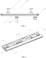
FIG. 1 is a schematic structural view of a medical suspension bridge in embodiment 1 of the application. -
FIG. 2 is a schematic structural view of a cross beam of the medical suspension bridge in embodiment 1 of the application. -
FIG. 3 is a cross-sectional view of the cross beam of the medical suspension bridge in embodiment 1 of the application. -
FIG. 4 is a schematic structural view of a connecting section in embodiment 1 of the application. -
FIG. 5 is a cross-sectional view of the medical suspension bridge in embodiment 1 of the application before a moving module is mounted. -
FIG. 6 is an enlarged view of position I inFIG. 5 . -
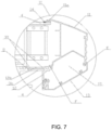
FIG. 7 is an enlarged view of position II inFIG. 5 . -
FIG. 8 is a cross-sectional view of the medical suspension bridge in embodiment 1 of the application after a moving module is mounted. -
FIG. 9 is a schematic structural view of a front cover plate of the medical suspension bridge in embodiment 1 of the application. -
FIG. 10 is a schematic view of a first routing groove of the medical suspension bridge in embodiment 1 of the application. -
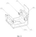
FIG. 11 is a schematic structural view of a moving module of the medical suspension bridge in embodiment 1 of the application. -
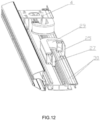
FIG. 12 is a schematic structural view after dustproof strips are mounted at the first routing groove inFIG. 10 . -
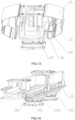
FIG. 13 is a schematic structural view of a medical suspension bridge in embodiment 2 of the application. -
FIG. 14 is a schematic structural view after a front panel assembly and a rear cover are removed inFIG. 13 . -
FIG. 15 is a schematic structural view of a second routing groove in embodiment 2 of the application. -
FIG. 16 is a schematic structural view after sealing strips are mounted on the second routing groove in embodiment 2 of the application. -
FIG. 17 is a schematic structural view of a moving module inFIG. 16 . -
FIG. 18 is schematic structural view of a roller assembly in embodiment 2 of the application. -
FIG. 19 is a schematic view of a flexible dustproof belt provided between dustproof belt rollers in embodiment 2 of the application. -
FIG. 20 is a sectional view of a rotating mechanism of the medical suspension bridge in the application. -
FIG. 21 is a sectional view in another view direction of the rotating mechanism of the medical suspension bridge in the application. -
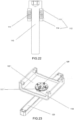
FIG. 22 is a schematic structural view of a tensioning device. -
FIG. 23 is a schematic three-dimensional structural view of a rotating mechanism of the medical suspension bridge in the application. -
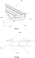
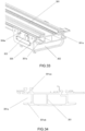
FIG. 24 is a schematic structural view of an airbag brake mechanism of the medical suspension bridge in the application. -
FIG. 25 is a schematic cross-sectional view of a guide rail inFIG. 24 . -
FIG. 26 is a schematic structural view after the guide rail inFIG. 24 is removed. -
FIG. 27 is a schematic structural view of an airbag brake module in the application. -
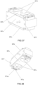
FIG. 28 is a schematic structural view of an airbag brake in the application. -
FIG. 29 is a schematic view of connection between an airbag brake, an air pipe, an electromagnetic valve and an air source in the application. -
FIG. 30 is a schematic planar view of an airbag brake in the application. -
FIG. 31 is a schematic structural view of an airbrake support frame in the application. -
FIG. 32 is a schematic structural view of a shaft shoulder screw in the application. -
FIG. 33 is a schematic structural view of an electromagnetic brake mechanism of the medical suspension bridge in the application. -
FIG. 34 is a schematic cross-sectional view of a guide rail inFIG. 33 . -
FIG. 35 is a schematic structural view after the guide rail inFIG. 33 is removed. -
FIG. 36 is a schematic structural view of an electromagnetic brake module in the application. -
FIG. 37 is a schematic structural view of an electromagnetic brake in the application. -
FIG. 38 is a schematic structural view in another view direction of the electromagnetic brake in the application. -
FIG. 39 is a schematic structural view of an electromagnetic brake support frame in the application. -
FIG. 40 is a schematic structural view of a shaft shoulder screw in the application. -
FIG. 41 is a schematic planar view of an electromagnetic brake in the application. - The technical solution of the application will be further non-restrictively described below in detail in combination with the preferred embodiments with reference to the drawings.
- Referring to
FIG. 1 , it illustrates a medical suspension bridge according to one preferred embodiment of the application. The medical suspension bridge includes a cross beam 1, suspension pipes 2 and a moving module 21. One ends of the suspension pipes 2 are connected with aceiling 100, and the other ends are connected with the cross beam 1. The number of the suspension pipes 2 is preferably two. The moving module 21 is movably connected to the cross beam 1, and the lower portion may be connected with a suspension bridge terminal box body (not shown, hereinafter referred to as the box body) containing electric and air terminals. - Referring to
FIG. 2 andFIG. 3 , the cross beam 1 includes a load-bearing beam 3, connectingsections 4, a front panel assembly 5, a rear panel assembly 6, and end covers 31. Acavity 28 is formed among the load-bearing beam 3, the front panel assembly 5 and the rear panel assembly 6, and the connectingsections 4 are provided in thecavity 28. The end covers 31 are located at the two ends of the cross beam 1, can protect the parts in thecavity 28 and can play a role of sealing, dust prevention, and appearance improvement. - Referring to
FIG. 4 to FIG. 8 , the upper ends of the connectingsections 4 are connected with the suspension pipes 2, and the lower ends are connected with the load-bearing beam 3. In the present embodiment, two connectingsections 4 are provided corresponding to the number of the suspension pipes 2. The connection mode of the connectingsections 4 and the suspension pipes 2 is as follows: four elongated holes 4a along the width direction of the medical suspension bridge are provided in the upper surfaces of the connectingsections 4, a connecting plate 2a is connected below the suspension pipes 2, four through holes (not shown) corresponding to the four elongated holes 4a are provided in the connecting plate 2a, and adjusting screws 2b pass through the through holes and the elongated holes 4a, and are connected with nuts 2c under the adjusting screws 2b, so as to connect the connecting plate 2a with the connectingsections 4. Moreover, the height and levelness of the cross beam 1 can be adjusted through the adjusting screws 2b, and the position of the cross beam 1 relative to the width direction of the suspension pipes 2 can be adjusted through the elongated holes. In order to enhance the stability of the connection, twomore adjusting nuts 2d may be provided on the adjusting screws 2b, one of which fits with the lower surface of the connecting plate 2a, and the other fits with the upper surface of the connectingsection 4. The upper portion of the connectingsection 4 is provided with an opening 4b for routing which is communicated with the suspension pipe 2; the lower portion of the connectingsection 4 is connected with the load-bearing beam 3 through bolts. - The front panel assembly 5 and the rear panel assembly 6 are respectively provided on the left side and right side of the cross beam 1.
- The front panel assembly 5 includes a front cover plate 7 and a front panel 8 which are connected with each other in a clamping manner. Referring to
FIG. 6 , the front cover plate 7 and the front panel 8 are respectively connected in a clamping manner through a first clamping part A and a second clamping part B. In addition to clamping, the connection of the front cover plate 7 and the front panel 8 may be supplemented with screw connection (not shown) to make the connection more firm. The upper portion of the front cover plate 7 is provided with an outwards convex first connecting part 7a, and the first connecting part 7a is connected with the upper surfaces of the connectingsections 4 through screws 9; the lower portion of the front cover plate 7 is connected with the upper surface of the load-bearing beam 3 through a third clamping part C. - A front
inner cavity 10 is formed between the front cover plate 7 and the front panel 8. Devices such as an electric socket, an air port and an LED lamp may be fixed on the front panel 8. The frontinner cavity 10 may accommodate electric wires, air pipes and the like to provide a routing passage. - The rear panel assembly 6 includes a rear cover plate 11, a rear cover
plate connecting plate 12 and arear panel 13 which are connected with one another in a clamping manner. Referring toFIG. 7 , the load-bearing beam 3 is provided with an outwardsconvex extension part 3b, the rear coverplate connecting plate 12 is provided with an outwards convex fitting part 12b, and the fitting part 12b is connected with theextension part 3b in a clamping manner through a fourth clamping part D; the upper portion of the rear cover plate 11 is provided with an outwards convex second connecting part 11a, and the second connecting part 11a is connected with the upper surfaces of the connectingsections 4 through screws 14; one end of therear panel 13 is connected with the rear cover plate 11 in a clamping manner through a fifth clamping part E, and the other end is connected with the rear coverplate connecting plate 12 in a clamping manner through a sixth clamping part F. Similarly, in addition to clamping among the rear cover plate 11, the rear coverplate connecting plate 12 and therear panel 13, the connection may be supplemented with screw connection (not shown) to make the connection more firm. - A rear inner cavity 15 is formed among the rear cover plate 11, the rear cover
plate connecting plate 12 and therear panel 13. Devices such as an electric socket, an air port and an LED may be fixed on therear panel 13, and the rear inner cavity 15 may accommodate electric wires, air pipes and the like to provide a routing passage. - Referring to
FIG. 9 , a first notch 7b is provided in the end portion of the front cover plate 7. The first notch 7b enables the frontinner cavity 10 and thecavity 28 to be communicated. The first notch 7b may be provided in only one end of the front cover plate 7 or in the two ends of the front cover plate 7 for the electric wires, air pipes and other parts in the frontinner cavity 10 to enter thecavity 28 through the first notch 7b, and then enter theceiling 100 through the opening 4b and the suspension pipes 2 at last. The rear cover plate 11 adopts the same structure as the front cover plate 7, that is, a second notch is provided in the end portion to make the electric wires, air pipes and other lines in the rear inner cavity 15 enter thecavity 28. By adopting such routing, the electric wires, air pipes and the like will not be exposed, such that the appearance is more attractive. - Referring to
FIG. 10 to FIG. 12 , a first groove along the length direction of the cross beam 1 is provided in the fitting part 12b of the rear coverplate connecting plate 12, and a second groove with a size and shape consistent with the size and shape of the first groove and communicated with the first groove is provided in theextension part 3b of the load-bearing beam 3. The first groove and the second groove jointly form afirst routing groove 20 that avoids a cablecarrier moving plate 25, and the cablecarrier moving plate 25 extends through thefirst routing groove 20 into thecavity 28. Guide rail grooves 3a are provided in the two sides of the load-bearing beam 3. The moving module 21 includes a movingframe 22, aroller 23 connected to the movingframe 22, arouting rack 24 and a cablecarrier moving plate 25. Therollers 23 are provided in the guide rail grooves 3a, and the moving module 21 can freely move along the cross beam 1 through theroller 23. Arouting hole 26 is formed among therouting rack 24, the movingframe 22 and the cablecarrier moving plate 25. A through hole 22a is provided in the bottom surface of the movingframe 22. - One end of the cable
carrier moving plate 25 is connected with the movingframe 22, and the other end passes through thefirst routing groove 20 and extends into thecavity 28. The medical suspension bridge further includes acable carrier 29 for routing, thecable carrier 29 is mounted in thecavity 28, one end of thecable carrier 29 is connected with the cablecarrier moving plate 25, and the other end is connected with a cable carrier fixedplate 27 which is fixedly connected with the load-bearing beam 3. When the movingframe 22 moves, the cablecarrier moving plate 25 can be driven to move, thus driving thecable carrier 29 to move. - Electric wires, air pipes and the like sequentially pass through the through hole 22a and the
routing hole 26 from the inside of the box body to enter thecable carrier 29, then sequentially pass through thecable carrier 29, the opening 4b and the suspension pipes 2, and finally enter theceiling 100. - Two
dustproof strips 30 which jointly seal thefirst routing groove 20 are mounted at thefirst routing groove 20, and the junction of the twodustproof strips 30 is approximately located in the middle portion of thefirst routing groove 20. The dustproof strips 30 are mounted on the upper surface of the rear coverplate connecting plate 12, and the mounting mode is preferably clamping. At therouting hole 26 of the movingframe 22, the electric wires, the air pipes and the cablecarrier moving plate 25 will squeeze away the dustproof strips 30, while the dustproof strips 30 at other positions will remain closed. In this way, the sealing and dustproof performance can be improved without hindering the movement of the movingframe 22. - The present embodiment has made certain changes on the basis of embodiment 1, so the same parts and components as that in embodiment 1 adopt the same reference signs, and the detailed description thereof is omitted. The following is only a detailed description of the changed structure.
- Referring to
FIG. 13 to FIG. 19 , the rear panel assembly 6 in the present embodiment includes two parts which are connected with each other in a clamping manner, i.e., arear cover 41 and a rearcover connecting plate 42. The rearcover connecting plate 42 is approximately Z-shaped, one end of which is connected with theextension part 3b through a fastener or bolt, the other end of which is connected with therear cover 41 in a clamping manner, and the middle portion of which is provided with a vertical side plate 42a; the upper end of therear cover 41 is connected with the upper surface of the connectingsection 4. In the present embodiment, thefirst routing groove 20 is not provided, but asecond routing groove 40 is provided in the side plate 42a of the rearcover connecting plate 42 and is also provided along the length direction of the cross beam 1, and the cablecarrier moving plate 25 extends through thesecond routing groove 40 into thecavity 28. The sidewall 22b of the movingframe 22 is provided with a pass-throughhole 22c, the cablecarrier moving plate 25 is made by bending a sheet metal, and the upper portion extends into thecavity 28 and is connected with the moving end of thecable carrier 29. The cablecarrier moving plate 25 is connected to the pass-throughhole 22c in a semi-enclosed manner, and together with the sidewall 22b forms a communicating cavity 32 that communicates the inside of the movingframe 22 and thecavity 28, and the communicating cavity 32 may be used for routing electric wires, air pipes and the like. - In this structure, the electric wire, air pipes and the like sequentially pass through the through hole 22a and the communicating cavity 32 from the inside of the box body, enter the
cable carrier 29, then sequentially pass through thecable carrier 29, the opening 4b and the suspension pipes 2, and finally enter theceiling 100. In order to improve the sealing and dustproof performance, the following structure may be used: aroller assembly 33 is connected on each of the two sides of the cablecarrier moving plate 25, theroller assembly 33 includes a roller support frame 33a and twodustproof belt rollers 33b provided in parallel on the roller support frame 33a, a flexibledustproof belt 34 is mounted at thefirst routing groove 20, the two ends of the flexibledustproof belt 34 are fixed on the side portion 12a of the rear coverplate connecting plate 12 through apressing plate 35, and the flexibledustproof belt 34 semi-encloses the outside of the cablecarrier moving plate 25, passes through the tworoller assemblies 33, and fits with fourdustproof belt rollers 33b of the two roller assemblies 33 (seeFIG. 16 for the specific arrangement mode of the flexibledustproof belt 34 and thedustproof belt rollers 33b). When the movingframe 22 moves, the cablecarrier moving plate 25 forces the flexibledustproof belt 34 to give way, and the flexibledustproof belt 34 at positions slightly away from the cablecarrier moving plate 25 can maintain the original state without being deformed, such that the sealing and dustproof performance is improved without hindering the movement of the movingframe 22. - The application at least has the following advantages:
- 1. Since cables such as electric wires and air pipes within the box body which needs to be moved are collectively mounted within the cable carrier, not only the routing is more tidy, but also the cables can be well protected.
- 2. Since the front inner cavity and the rear inner cavity for routing and arranging are provided, the arrangement in the front inner cavity and the rear inner cavity is clear and tidy, and is not easily confused.
- 3. Since the middle portion of the load-bearing beam is not provided with a groove for routing, the influence on the overall strength of the cross beam is smaller and the length of the groove can be increased, so as to prolong the moving distance of the lower box body and facilitate the use.
- 4. The sealing performance is good, the dustproof effect is good and no influence is caused to the movement of the moving module.
- 5. Since electric wires, air pipes and the like are all collected in the medical suspension bridge, the appearance is attractive.
- Referring to
FIG. 20-23 , the medical suspension bridge includes ashaft seat 102 and asuspension arm 120. The rotating mechanism of the medical suspension bridge of the application includes arotating shaft 101, aplastic shaft sleeve 103, atensioning device 109, afriction device 115, anejection device 116, a limitingscrew 117, and a limitingblock 118. Therotating shaft 101 is connected between theshaft seat 102 and thesuspension arm 120, theplastic shaft sleeve 103 is connected to therotating shaft 101, theshaft seat 102 is partially embedded in theplastic shaft sleeve 103, and therotating shaft 101 drives thesuspension arm 120 to rotate relative to theshaft seat 102. Theplastic shaft sleeve 103 can reduce the wear of therotating shaft 101 and theshaft seat 102. Thetensioning device 109 is connected to therotating shaft 101, and theejection device 116 is provided in therotating shaft 101. Thefriction device 115 is provided between therotating shaft 101 and theplastic shaft sleeve 103, one end of thefriction device 115 is fixedly connected with therotating shaft 101, and the other end presses against theplastic shaft sleeve 103. Thefriction device 115 can increase the friction force between therotating shaft 101 and theplastic shaft sleeve 103, such that the suspension arm does not rotate freely relative to theshaft seat 102. The limitingscrew 117 is connected with therotating shaft 101, the limitingblock 118 is provided on theshaft seat 102, and the limitingscrew 117 is used together with the limitingblock 118 to realize the rotation limitation of therotating shaft 101. - Further referring to
FIG. 20 and FIG. 21 , therotating shaft 101 includes anupper shaft member 104 and alower shaft member 105. The central position of the rotating shaft is provided with a through hole. Such design can not only facilitate routing, but also reduce the weight of the rotating shaft itself. Thetensioning device 109 is connected between theupper shaft member 104 and thelower shaft member 105, and theplastic shaft sleeve 103 is clamped between theupper shaft member 104 and thelower shaft member 105, so as to clamp theshaft seat 102 partially embedded in theplastic shaft sleeve 103, such that therotating shaft 101 is capable of rotating relative to theshaft seat 102. One end of thelower shaft member 105 is fixedly connected with thesuspension arm 120, so thesuspension arm 120 can rotate with therotating shaft 101 relative to theshaft seat 102. Theupper shaft member 104 is provided with a throughhole 119, theejection device 116 is mounted in the throughhole 119, and one end of theejection device 116 presses against thelower shaft member 105. The clamping force between theupper shaft member 104 and thelower shaft member 105 can be adjusted by adjusting the tightening force of thetensioning device 109 and theejection device 116, so as to adjust the rotation tightness between theshaft seat 102 and therotating shaft 101. Theplastic shaft sleeve 103 includes anupper shaft sleeve 107 and alower shaft sleeve 108, theupper shaft sleeve 107 and thelower shaft sleeve 108 are symmetrically provided, theupper shaft sleeve 107 is provided between theupper shaft member 104 and theshaft seat 102, thelower shaft sleeve 108 is provided between thelower shaft member 105 and theshaft seat 102, and one end of thelower shaft sleeve 108 presses against thefriction device 115. Theplastic shaft sleeve 103 is divided into anupper shaft sleeve 107 and alower shaft sleeve 108 to facilitate mounting. - Further referring to
FIG. 20 andFIG. 22 , thetensioning device 109 includes atensioning screw 110, adisc spring assembly 111, and agasket 112. Thetensioning screw 110 passes through theupper shaft member 104 and is connected with thelower shaft member 105, and thedisc spring assembly 111 and thegasket 112 are provided on thetensioning screw 110 in a sleeving manner. Thegasket 112 includes afirst gasket 113 and asecond gasket 114. Thefirst gasket 113 and thesecond gasket 114 are respectively provided at the two ends of thedisc spring assembly 111, and respectively press against a nut of thetensioning screw 110 and theupper shaft member 104. Thegasket 112 can reduce the wear of thedisc spring assembly 111. When thetensioning screw 110 is locked, thedisc spring assembly 111 will be compressed, such that the tightening force between theupper shaft member 104 and thelower shaft member 105 can be adjusted conveniently. Moreover, when theplastic shaft sleeve 103 is worn to a certain extent, thedisc spring assembly 111 can automatically compensate for the wear and ensure that the rotation torque changes little. - The rotating mechanism of the medical suspension bridge provided by the application uses the plastic shaft sleeve to replace the metal bearing, the cost is reduced, and the rotation tightness can be adjusted.
- Referring to
FIG. 24 , it illustrates an airbag brake mechanism of the medical suspension bridge according to one preferred embodiment of the application, which includes aguide rail 201, a movingmodule 202 movably connected to theguide rail 201 and anairbag brake module 203 mounted on the movingmodule 202. - Referring to
FIG. 25 to FIG. 27 , theguide rail 201 is preferably an aluminum section guide rail,guide rail grooves 201a are symmetrically provided in the two sides, and eachguide rail groove 201a includes an upper sidewall 201aa and a lower sidewall 201ab which are provided opposite to each other. The movingmodule 202 includes a movingframe 204 with a U-shaped cross section and four movingrollers 205 symmetrically provided on the movingframe 204. The movingrollers 205 are clamped in theguide rail grooves 201a, and fit with the upper sidewall 201aa and the lower sidewall 201ab of theguide rail grooves 201a. The movingmodule 202 is connected to theguide rail 201 through the movingrollers 205, and moves along theguide rail grooves 201a through the movingrollers 205. - The two sides of the moving
frame 204 are symmetrically provided with mountingports 204a, and theairbag brake module 203 is mounted in the mountingports 204a. Theairbag brake module 203 includes an airbagbrake support frame 206 and anairbag brake 207. The airbagbrake support frame 206 is fixedly connected to the movingframe 204 through screws, theairbag brake 207 is mounted on the airbagbrake support frame 206 through theshaft shoulder screw 208, and theairbag brake 207 is located in theguide rail grooves 201a. - Referring to
FIG. 28 to FIG. 30 , theairbag brake 207 includes abase 207a, anupper airbag 207b provided on the upper portion of thebase 207a, and alower airbag 207c provided at the lower portion of thebase 207a. Theupper airbag 207b and thelower airbag 207c are connected with anair source 211 through anair pipe 209, and anelectromagnetic valve 210 is provided on theair pipe 209 to control theupper airbag 207b and thelower airbag 207c to deflate or theair source 211 to inflate theupper airbag 207b and thelower airbag 207c. When theupper airbag 207b is mounted in thebase 207a, it may protrude or not protrude out of the upper surface of thebase 207a, but after being expanded by inflation, part of theupper airbag 207b will protrude out of the upper surface of thebase 207a and press against the upper sidewall 201aa. Similarly, when thelower airbag 207c is mounted in thebase 207a, it may also protrude or not protrude out of the lower surface of thebase 207a. However, after being expanded by inflation, part of thelower airbag 207c will protrude out of the upper surface of thebase 207a and press against the lower sidewall 201ab. Under normal conditions (when the moving module does not need to move), theupper airbag 207b andlower airbag 207c of theairbag brake 207 are in an inflated state, they press against theupper sidewall 201a and the lower sidewall 201ab of theguide rail grooves 201a, so as to fix the movingmodule 202 on theguide rail 201. When the movingmodule 202 needs to move, theelectromagnetic valve 210 is used to control theupper airbag 207b and thelower airbag 207c to deflate, such that theupper airbag 207b and thelower airbag 207c are separated from theguide rail grooves 201a. At this time, the movingmodule 202 can be pushed to move on theguide rail 201. - Referring to
FIG. 28 ,FIG. 31 andFIG. 32 , the specific connection mode of theairbag brake 207 and the airbagbrake support frame 206 is as follows: twoelongated holes 206a provided in the vertical direction are provided in the airbagbrake support frame 206, twoscrew holes 207d for mounting are provided in thebase 207a of theairbag brake 207, theshaft shoulder screw 208 is provided with ashaft shoulder 208b between ascrew head 208a and a threadedpart 208c, and theshaft shoulder 208b fits with theelongated hole 206a. Theshaft shoulder screw 208 passes through theelongated hole 206a and is in threaded connection with the threadedhole 207d. After connection, theairbag brake 207 can slide freely along theelongated hole 206a through theshaft shoulder screw 208, that is, theairbag brake 207 is float-connected to the airbagbrake support frame 206. The advantage of this structure lies in that the requirement on the size accuracy of theguide rail 201 and theairbag brake 207 is low. When theupper airbag 207b and thelower airbag 207c of theairbag brake 207 respectively press against the upper sidewall 201aa and the lower sidewall 201ab of theguide rail grooves 201a, the position of theairbag brake 207 can be adjusted freely in theelongated hole 206a to adapt to the mounting and size error of theguide rail 201 and theairbag brake 207, such that theupper airbag 207b and thelower airbag 207c can respectively fit with the upper sidewall 201aa and the lower sidewall 201ab of theguide rail grooves 201a more closely, and the reliability and stability of the brake are improved. - In order to prevent the
airbag brake 207 from moving downwards under the effect of gravity after deflation, resulting in contact between thebase 207a and the lower sidewall 201ab, such that the noise is increased and the use is influenced during movement, the size may be designed such that thebase 207 is not in contact with the lower sidewall 201ab when thebase 207a is located at the bottom portion, or a part still protrudes out of the lower surface after thelower airbag 207c is deflated, such that the soft airbag rubs the lower sidewall 201ab, which can effectively reduce the frictional resistance and noise. - The airbag brake mechanism of the medical suspension bridge of the application at least includes the following advantages:
- 1. When braking, the airbag brake mechanism of the application has two airbag surfaces squeezing the guide rail grooves, so the friction force is larger, the braking effect is better, and the unexpected drift of the moving module is effectively prevented.
- 2. The airbag brake mechanism of the application is float-connected to the airbag brake support frame, the requirements on the size and mounting accuracy of the guide rail and the airbag brake are low, and it is more convenient and reliable to use.
- 3. The friction noise is low when the moving module of the application moves.
- Referring to
FIG. 33 , it illustrates an electromagnetic brake mechanism of the medical suspension bridge according to one preferred embodiment of the application, which includes aguide rail 301, a movingmodule 302 movably connected to theguide rail 301, and anelectromagnetic brake module 303 mounted on the movingmodule 302. - Referring to
FIG. 34 to FIG. 36 , theguide rail 301 is preferably an aluminum section guide rail,guide rail grooves 301a are symmetrically provided in the two sides, and eachguide rail groove 301a includes an upper sidewall 301aa and a lower sidewall 301ab. The movingmodule 302 includes a movingframe 304 with a U-shaped cross section and four movingrollers 305 symmetrically provided on the movingframe 304. The movingrollers 305 are provided in theguide rail grooves 301a in a clamping manner, and fit with the upper sidewall 301aa and the lower sidewall 301ab of theguide rail grooves 301a. The movingmodule 302 is connected to theguide rail 301 through the movingrollers 305, and moves along theguide rail grooves 301a through the movingrollers 305. - The two sides of the moving
frame 304 are symmetrically provided with mountingports 304a, and theelectromagnetic brake module 303 is mounted in the mountingports 304a. Theelectromagnetic brake module 303 includes an electromagneticbrake support frame 306 and anelectromagnetic brake 307. The electromagneticbrake support frame 306 is fixedly connected to the movingframe 304 through screws, theelectromagnetic brake 307 is mounted on the electromagneticbrake support frame 306 through theshaft shoulder screw 308, and theelectromagnetic brake 307 is located in theguide rail grooves 301a. - Referring to
FIG. 37 to FIG. 38 , theelectromagnetic brake 307 includes abase 307a, a coil (not shown) provided in thebase 307a, anupper armature 307b and alower armature 307c respectively provided on the upper side and the lower side of thebase 307a, and a plurality of compression springs (not shown) provided in the base and including the two ends which respectively press against theupper armature 307b and thelower armature 307c. When the coil is not electrified, theupper armature 307b and thelower armature 307c extend out under the effect of elastic force and respectively press against the upper sidewall 301aa and the lower sidewall 301ab of theguide rail grooves 301a, so as to fix the movingmodule 302 on theguide rail 301. When the coil is electrified, attracting force is produced to theupper armature 307b and thelower armature 307c, such that theupper armature 307b and thelower armature 307c will retract by overcoming the elastic force. At this time, the movingmodule 302 can be pushed to move on theguide rail 301. - In order to enhance the braking force of the
electromagnetic brake 307 and theguide rail 301, anupper friction plate 307d and alower friction plate 307e are respectively provided on theupper armature 307b and thelower armature 307c. - Referring to
FIG. 39 to FIG. 40 , the specific connection mode of theelectromagnetic brake 307 and the electromagneticbrake support frame 306 is as follows: twoelongated holes 306a provided in the vertical direction are provided in the electromagneticbrake support frame 306, two threadedholes 307f for mounting are provided in theelectromagnetic brake 307, theshaft shoulder screw 308 is provided with ashaft shoulder 308b between ascrew head 308a and a threadedpart 308c, and theshaft shoulder 308b fits with theelongated holes 306a. The shaft shoulder screws 308 penetrate through theelongated holes 306a and are in threaded connection with the threadedholes 307f. After connection, theelectromagnetic brake 307 can slide freely along theelongated holes 306a through the shaft shoulder screws 308. The advantage of this structure lies in that the requirement on the size accuracy of theguide rail 301 and theelectromagnetic brake 307 is low. When theupper armature 307b and thelower armature 307c of theelectromagnetic brake 307 respectively press against the upper sidewall 301aa and the lower sidewall 301ab of theguide rail grooves 301a, the position of theelectromagnetic brake 307 can be adjusted in theelongated holes 306a to adapt to the mounting and size error of theguide rail 301 and theelectromagnetic brake 307, such that theupper friction plate 307d and thelower friction plate 307e can respectively fit with the upper sidewall 301aa and the lower sidewall 301ab of theguide grooves 301a more closely, and the reliability and stability of the brake are improved. - Referring to
FIG. 38 andFIG. 41 , in order to prevent theelectromagnetic brake 307 from moving downwards under the effect of gravity after the coil is electrified, resulting in friction between thelower friction plate 307e and the lower sidewall 301ab, such that the use is influenced, aball plunger 307g is mounted on the lower surface of thebase 307a. A ball head 307ga at the top of theball plunger 307g is in contact with the lower sidewall 301ab when thelower armature 307c is retracted, so as to prevent thelower friction plate 307e from being in contact with the lower sidewall 301ab. When the movingmodule 302 is pushed to move, the ball head 307ga rolls, the movingmodule 302 can be pushed to move by applying very small force, and no friction noise is produced. - The electromagnetic brake mechanism of the medical suspension bridge of the application at least has the following advantages:
- 1. In the medical suspension bridge provided by the application, by changing the traditional airbag brake into the electromagnetic brake, the response speed is fast, the use reliability is high, it is not easily damaged, the service life is longer, no compressed air is used to drive, the structure is simple and the volume is small.
- 2. Since the electromagnetic brake mechanism of the application is provided with the upper armature and the lower armature, which can press against the guide rail grooves to play a role of braking, the braking effect is better than that of a unilateral armature.
- 3. Since the electromagnetic brake of the application is movably connected with the electromagnetic brake support frame, the requirements on the size and mounting accuracy of the guide rail and the electromagnetic brake are low, and it is more convenient and reliable to use.
- 4. Since the friction plate is not in contact with the guide rail when the moving module moves, the friction noise is low.
Claims (12)
- A medical suspension bridge, comprising a cross beam (1), a suspension pipe (2), a moving module (21) and a box body connected with the moving module (21), the cross beam (1) being connected with the suspension pipe (2), the moving module (21) being movably connected with the cross beam (1), wherein the medical suspension bridge further comprises a cable carrier (29), electric wires and air pipes, the cross beam (1) comprises a load-bearing beam (3), the moving module (21) comprises a cable carrier moving plate (25) extending to the upper portion of the load-bearing beam (3), one end of the cable carrier (29) is connected to the load-bearing beam (3), the other end is connected to the cable carrier moving plate (25), the electric wires and the air pipes enter the suspension pipe (2) through the moving module (21) and the cable carrier (29) from the inside of the box body;wherein the cross beam (1) further comprises a rear panel assembly (6) connected to one side of the load-bearing beam (3);wherein the rear panel assembly (6) comprises a rear cover plate connecting plate (12) connected with the load-bearing beam (3), the load-bearing beam (3) is provided with an outwards convex extension part (3b), the rear cover plate connecting plate (12) is provided with an outwards convex fitting part (12b), and the fitting part (12b) and the extension part (3b) are connected with each other in a clamping manner;wherein a first groove is provided in the fitting part (12b), a second groove is provided in the extension part (3b), the first groove and the second groove run through each other to jointly form a first routing groove (20) that avoids the cable carrier moving plate (25), and the cable carrier moving plate (25) extends through the first routing groove (20) to the upper portion of the load-bearing beam (3).
- The medical suspension bridge according to claim 1, wherein two dustproof strips (30) which jointly seal the first routing groove (20) are mounted at the first routing groove (20).
- The medical suspension bridge according to claim 1, wherein the rear panel assembly (6) further comprises a rear cover plate (11) and a rear panel (13), the rear cover plate (11), the rear cover plate connecting plate (12) and the rear panel (13) are connected with one another in a clamping manner, and a rear inner cavity (15) is formed among the rear cover plate (11), the rear cover plate connecting plate (12) and the rear panel (13).
- The medical suspension bridge according to claim 1, wherein the cross beam (1) further comprises a front panel assembly (5) connected to the other side of the load-bearing beam (3), the front panel assembly (5) comprises a front cover plate (7) and a front panel (8) connected with each other in a clamping manner, and the front cover plate (7) and the front panel (8) fit with each other to form a front inner cavity (10).
- The medical suspension bridge according to claim 1, wherein the rear panel assembly comprises a rear cover (41) and a rear cover connecting plate (42) connected with each other in a clamping manner, the rear cover connecting plate (42) is provided with a side plate (42a), the side plate (42a) is provided with a second routing groove (40) that avoids the cable carrier moving plate (25), and one end of the cable carrier moving plate (25) extends through the second routing groove (40) to the upper portion of the load-bearing beam (3).
- The medical suspension bridge according to claim 5, wherein the two sides of the cable carrier moving plate (25) are connected with roller assemblies (33), a flexible dustproof belt (34) covering the second routing groove (40) is mounted on a side portion (12a) of the rear cover plate connecting plate (12), and the flexible dustproof belt (34) passes through the roller assemblies (33) and semi-encloses the outside of the cable carrier moving plate (25).
- The medical suspension bridge according to claim 6, wherein each roller assembly (33) comprises a roller support frame (33a) and at least one dustproof belt roller (33b) mounted on the roller support frame (33a).
- The medical suspension bridge according to claim 1, wherein the medical suspension bridge further comprises a rotating mechanism, a shaft seat (102) and a suspension arm (120), the suspension arm (120) is rotatably connected to the shaft seat (102) through the rotating mechanism, the rotating mechanism comprises a rotating shaft (101) and a plastic shaft sleeve (103), the plastic shaft sleeve (103) is connected to the rotating shaft (101), the shaft seat (102) is partially embedded in the plastic shaft sleeve (103), and the rotating shaft (101) drives the suspension arm (120) to rotate relative to the shaft seat (102).
- The medical suspension bridge according to claim 1, wherein the medical suspension bridge further comprises an airbag brake mechanism, the airbag brake mechanism comprises a guide rail (201), a moving module (202) movably connected to the guide rail (201) and an airbag brake module (203) fixedly connected with the moving module (202), the guide rail (201) is provided with guide rail grooves (201a), the airbag brake module (203) comprises an airbag brake (207) located in the guide rail grooves (201a), each guide rail groove (201a) comprises an upper sidewall (201aa) and a lower sidewall (201ab) which are provided opposite to each other, and the airbag brake (207) tightly presses against the upper sidewall (201aa) and the lower sidewall (201ab) during braking.
- The medical suspension bridge according to claim 9, wherein the airbag brake (207) comprises a base (207a), and an upper airbag (207b) and a lower airbag (207c) respectively provided at the upper portion and lower portion of the base (207a).
- The medical suspension bridge according to claim 1, wherein the medical suspension bridge further comprises an electromagnetic brake mechanism, the electromagnetic brake mechanism comprises a guide rail (301), a moving module (302) movably connected to the guide rail (301), and an electromagnetic brake module (303) fixedly connected with the moving module (302), the guide rail (301) is provided with guide rail grooves (301a), and the electromagnetic brake module (303) comprises an electromagnetic brake (307) located in the guide rail grooves (301a).
- The medical suspension bridge according to claim 11, wherein each guide rail groove (301a) comprises an upper sidewall (301aa) and a lower sidewall (301ab) provided opposite to each other, the electromagnetic brake (307) comprises an upper armature (307b), a lower armature (307c) and a compression spring provided between the upper armature (307b) and the lower armature (307c), the upper armature (307b) is capable of pressing against the upper sidewall (301aa) under the elastic force of the compression spring, and the lower armature (307c) is capable of pressing against the lower sidewall (301ab) under the elastic force of the compression spring.
Applications Claiming Priority (5)
| Application Number | Priority Date | Filing Date | Title |
|---|---|---|---|
| CN201810066557.3A CN108066090B (en) | 2018-01-24 | 2018-01-24 | Rotating mechanism of medical suspension bridge |
| CN201810067702.XA CN108194539A (en) | 2018-01-24 | 2018-01-24 | A kind of electromagnetic brake mechanism of medical bridge tower crane |
| CN201810066363.3A CN108087459A (en) | 2018-01-24 | 2018-01-24 | A kind of air bag braking mechanism of medical bridge tower crane |
| CN201810117493.5A CN108175622B (en) | 2018-02-06 | 2018-02-06 | Medical suspension bridge |
| PCT/CN2018/121088 WO2019144725A1 (en) | 2018-01-24 | 2018-12-14 | Medical suspension bridge |
Publications (3)
| Publication Number | Publication Date |
|---|---|
| EP3744300A1 EP3744300A1 (en) | 2020-12-02 |
| EP3744300A4 EP3744300A4 (en) | 2021-11-03 |
| EP3744300B1 true EP3744300B1 (en) | 2024-04-17 |
Family
ID=67395255
Family Applications (1)
| Application Number | Title | Priority Date | Filing Date |
|---|---|---|---|
| EP18903024.0A Active EP3744300B1 (en) | 2018-01-24 | 2018-12-14 | Medical suspension bridge |
Country Status (6)
| Country | Link |
|---|---|
| US (1) | US11925584B2 (en) |
| EP (1) | EP3744300B1 (en) |
| JP (1) | JP6997330B2 (en) |
| MY (1) | MY195699A (en) |
| SG (1) | SG11202007043QA (en) |
| WO (1) | WO2019144725A1 (en) |
Families Citing this family (2)
| Publication number | Priority date | Publication date | Assignee | Title |
|---|---|---|---|---|
| CN218923041U (en) * | 2022-11-23 | 2023-04-28 | 上海西门子医疗器械有限公司 | Brake mechanism and hospital bed |
| CN119370777A (en) * | 2024-12-31 | 2025-01-28 | 成都思越智能装备股份有限公司 | A sealed forklift for clean room use |
Family Cites Families (26)
| Publication number | Priority date | Publication date | Assignee | Title |
|---|---|---|---|---|
| DE4416618C1 (en) * | 1994-05-11 | 1995-07-13 | Draegerwerk Ag | Care unit for medical treatment appts |
| US5829723A (en) * | 1995-06-28 | 1998-11-03 | Medex, Inc. | Medical device mounting structure |
| DE29608033U1 (en) | 1996-05-03 | 1996-08-01 | MAVIG GmbH, 81829 München | Hanger with cable trolley |
| DE19910289A1 (en) * | 1999-03-09 | 2000-09-21 | Kreuzer Gmbh & Co Ohg | Furnished with an operating table top removably mounted on a stand |
| CA2518160A1 (en) | 2003-03-18 | 2004-09-30 | Hill-Rom Services, Inc. | Radial arm system for patient care equipment |
| US7770860B1 (en) * | 2005-11-10 | 2010-08-10 | Modular Services Company | Medical service system on articulating arm with electromagnetic brakes |
| CN201710581U (en) | 2010-05-18 | 2011-01-19 | 南京迈瑞生物医疗电子有限公司 | Medical pendant rotational joint and medical pendant |
| CN102269229B (en) | 2010-06-02 | 2013-03-20 | 南京迈瑞生物医疗电子有限公司 | Rotating joint and rotating joint component |
| US8584274B2 (en) | 2011-04-22 | 2013-11-19 | Medtrak Holding Company, Llc | Patient support and transport system |
| CN103181823B (en) | 2011-12-30 | 2016-04-20 | 北京谊安医疗系统股份有限公司 | Medical hanging bridge and slide thereof |
| WO2015062367A1 (en) * | 2013-10-29 | 2015-05-07 | 湖南太阳龙医疗科技有限公司 | Combined system and method of icu bridge care unit |
| CN103912609B (en) | 2014-04-24 | 2016-05-18 | 迈柯唯医疗设备(苏州)有限公司 | A kind of snap-in electromagnetic brake |
| CN204050147U (en) * | 2014-07-31 | 2014-12-31 | 南京浦菲凯尔医疗器械有限公司 | Medical hanging bridge is hung oneself from a beam |
| CN204839735U (en) | 2015-02-12 | 2015-12-09 | 南京迈瑞生物医疗电子有限公司 | Medical tower crane joint subassembly and medical tower crane |
| CN105167850A (en) * | 2015-07-13 | 2015-12-23 | 南京鼎瑞医疗器械有限公司 | Cross beam for medical suspension bridge |
| CN205307104U (en) | 2015-12-29 | 2016-06-15 | 易勇 | Medical tower crane and pivot mechanism thereof |
| CN205729694U (en) | 2016-01-20 | 2016-11-30 | 南京迈瑞生物医疗电子有限公司 | A kind of overarm device |
| CN205569248U (en) | 2016-03-21 | 2016-09-14 | 易勇 | Medical pendant |
| CN205729695U (en) * | 2016-03-30 | 2016-11-30 | 易勇 | Pivot structure and Medical hanging bridge |
| CN206362548U (en) | 2016-12-30 | 2017-07-28 | 天津市北方阀门控制设备有限公司 | A kind of loading device for valve actuator life test |
| CN108194539A (en) | 2018-01-24 | 2018-06-22 | 迈柯唯医疗设备(苏州)有限公司 | A kind of electromagnetic brake mechanism of medical bridge tower crane |
| CN108066090B (en) | 2018-01-24 | 2020-09-15 | 迈柯唯医疗设备(苏州)有限公司 | Rotating mechanism of medical suspension bridge |
| CN108087459A (en) | 2018-01-24 | 2018-05-29 | 迈柯唯医疗设备(苏州)有限公司 | A kind of air bag braking mechanism of medical bridge tower crane |
| CN108175622B (en) | 2018-02-06 | 2021-12-28 | 迈柯唯医疗设备(苏州)有限公司 | Medical suspension bridge |
| CN207777462U (en) | 2018-01-24 | 2018-08-28 | 迈柯唯医疗设备(苏州)有限公司 | A kind of electromagnetic brake mechanism of medical bridge tower crane |
| CN208442182U (en) | 2018-01-24 | 2019-01-29 | 迈柯唯医疗设备(苏州)有限公司 | An airbag brake mechanism for a medical bridge tower |
-
2018
- 2018-12-14 WO PCT/CN2018/121088 patent/WO2019144725A1/en not_active Ceased
- 2018-12-14 US US16/964,824 patent/US11925584B2/en active Active
- 2018-12-14 MY MYPI2020003835A patent/MY195699A/en unknown
- 2018-12-14 EP EP18903024.0A patent/EP3744300B1/en active Active
- 2018-12-14 SG SG11202007043QA patent/SG11202007043QA/en unknown
- 2018-12-14 JP JP2020540615A patent/JP6997330B2/en active Active
Also Published As
| Publication number | Publication date |
|---|---|
| EP3744300A4 (en) | 2021-11-03 |
| US11925584B2 (en) | 2024-03-12 |
| MY195699A (en) | 2023-02-06 |
| SG11202007043QA (en) | 2020-08-28 |
| WO2019144725A1 (en) | 2019-08-01 |
| EP3744300A1 (en) | 2020-12-02 |
| JP6997330B2 (en) | 2022-01-17 |
| JP2021511868A (en) | 2021-05-13 |
| US20210059883A1 (en) | 2021-03-04 |
Similar Documents
| Publication | Publication Date | Title |
|---|---|---|
| US8152214B2 (en) | Gripper with self-compensating jaw guides | |
| CA2521290A1 (en) | Axle clamp assembly top pad and air spring mounting assembly | |
| KR101048145B1 (en) | Door Gripper | |
| CN111862797B (en) | Bonding method, bonding apparatus and readable storage medium | |
| EP3744300A1 (en) | Medical suspension bridge | |
| EP2876018A1 (en) | Bogie of rail vehicle | |
| CN111862796B (en) | Laminating subassembly, laminating pad and laminating equipment | |
| KR101371454B1 (en) | Moving device | |
| CN112265562B (en) | Adjustable elastic pressing guide wheel device | |
| US11590991B2 (en) | Bogie and rail vehicle | |
| CN101166646B (en) | Collector shoe device | |
| CN105485576A (en) | Bridge decorative lamp mounting device capable of alarming to prompt and with guiding groove | |
| WO2000039018A3 (en) | Holding brake for a traction sheave elevator | |
| CN111862795B (en) | Laminating equipment | |
| KR20140025388A (en) | A rail vehicle brake actuator with a brake block holder | |
| CN120171475B (en) | A band spring brake and its braking system | |
| CN109162552B (en) | Guide rail device and sliding door | |
| CN108175622A (en) | A kind of Medical hanging bridge | |
| CN114242527A (en) | Intelligent circuit breaker bridging structure and intelligent circuit breaker | |
| CN214932926U (en) | Guide wheel subassembly and shuttle | |
| EP0698170A1 (en) | Opening and closing device for door | |
| CN111571741B (en) | Integrated double-shaft gluing mechanism of automatic edge bonding machine | |
| CN210240505U (en) | Totally-enclosed linear module structure | |
| CN215567313U (en) | Compact slide mechanism | |
| KR20150050931A (en) | Transport apparatus for riser tensioner |
Legal Events
| Date | Code | Title | Description |
|---|---|---|---|
| STAA | Information on the status of an ep patent application or granted ep patent |
Free format text: STATUS: THE INTERNATIONAL PUBLICATION HAS BEEN MADE |
|
| PUAI | Public reference made under article 153(3) epc to a published international application that has entered the european phase |
Free format text: ORIGINAL CODE: 0009012 |
|
| STAA | Information on the status of an ep patent application or granted ep patent |
Free format text: STATUS: REQUEST FOR EXAMINATION WAS MADE |
|
| 17P | Request for examination filed |
Effective date: 20200803 |
|
| AK | Designated contracting states |
Kind code of ref document: A1 Designated state(s): AL AT BE BG CH CY CZ DE DK EE ES FI FR GB GR HR HU IE IS IT LI LT LU LV MC MK MT NL NO PL PT RO RS SE SI SK SM TR |
|
| AX | Request for extension of the european patent |
Extension state: BA ME |
|
| DAV | Request for validation of the european patent (deleted) | ||
| DAX | Request for extension of the european patent (deleted) | ||
| A4 | Supplementary search report drawn up and despatched |
Effective date: 20210930 |
|
| RIC1 | Information provided on ipc code assigned before grant |
Ipc: A61G 12/00 20060101AFI20210924BHEP |
|
| GRAP | Despatch of communication of intention to grant a patent |
Free format text: ORIGINAL CODE: EPIDOSNIGR1 |
|
| STAA | Information on the status of an ep patent application or granted ep patent |
Free format text: STATUS: GRANT OF PATENT IS INTENDED |
|
| INTG | Intention to grant announced |
Effective date: 20231128 |
|
| GRAS | Grant fee paid |
Free format text: ORIGINAL CODE: EPIDOSNIGR3 |
|
| GRAA | (expected) grant |
Free format text: ORIGINAL CODE: 0009210 |
|
| STAA | Information on the status of an ep patent application or granted ep patent |
Free format text: STATUS: THE PATENT HAS BEEN GRANTED |
|
| AK | Designated contracting states |
Kind code of ref document: B1 Designated state(s): AL AT BE BG CH CY CZ DE DK EE ES FI FR GB GR HR HU IE IS IT LI LT LU LV MC MK MT NL NO PL PT RO RS SE SI SK SM TR |
|
| REG | Reference to a national code |
Ref country code: GB Ref legal event code: FG4D |
|
| REG | Reference to a national code |
Ref country code: CH Ref legal event code: EP |
|
| REG | Reference to a national code |
Ref country code: IE Ref legal event code: FG4D Ref country code: DE Ref legal event code: R096 Ref document number: 602018068382 Country of ref document: DE |
|
| REG | Reference to a national code |
Ref country code: LT Ref legal event code: MG9D |
|
| REG | Reference to a national code |
Ref country code: NL Ref legal event code: MP Effective date: 20240417 |
|
| REG | Reference to a national code |
Ref country code: AT Ref legal event code: MK05 Ref document number: 1676542 Country of ref document: AT Kind code of ref document: T Effective date: 20240417 |
|
| PG25 | Lapsed in a contracting state [announced via postgrant information from national office to epo] |
Ref country code: NL Free format text: LAPSE BECAUSE OF FAILURE TO SUBMIT A TRANSLATION OF THE DESCRIPTION OR TO PAY THE FEE WITHIN THE PRESCRIBED TIME-LIMIT Effective date: 20240417 |
|
| PG25 | Lapsed in a contracting state [announced via postgrant information from national office to epo] |
Ref country code: NL Free format text: LAPSE BECAUSE OF FAILURE TO SUBMIT A TRANSLATION OF THE DESCRIPTION OR TO PAY THE FEE WITHIN THE PRESCRIBED TIME-LIMIT Effective date: 20240417 |
|
| PG25 | Lapsed in a contracting state [announced via postgrant information from national office to epo] |
Ref country code: IS Free format text: LAPSE BECAUSE OF FAILURE TO SUBMIT A TRANSLATION OF THE DESCRIPTION OR TO PAY THE FEE WITHIN THE PRESCRIBED TIME-LIMIT Effective date: 20240817 |
|
| PG25 | Lapsed in a contracting state [announced via postgrant information from national office to epo] |
Ref country code: BG Free format text: LAPSE BECAUSE OF FAILURE TO SUBMIT A TRANSLATION OF THE DESCRIPTION OR TO PAY THE FEE WITHIN THE PRESCRIBED TIME-LIMIT Effective date: 20240417 |
|
| PG25 | Lapsed in a contracting state [announced via postgrant information from national office to epo] |
Ref country code: HR Free format text: LAPSE BECAUSE OF FAILURE TO SUBMIT A TRANSLATION OF THE DESCRIPTION OR TO PAY THE FEE WITHIN THE PRESCRIBED TIME-LIMIT Effective date: 20240417 Ref country code: FI Free format text: LAPSE BECAUSE OF FAILURE TO SUBMIT A TRANSLATION OF THE DESCRIPTION OR TO PAY THE FEE WITHIN THE PRESCRIBED TIME-LIMIT Effective date: 20240417 |
|
| PG25 | Lapsed in a contracting state [announced via postgrant information from national office to epo] |
Ref country code: GR Free format text: LAPSE BECAUSE OF FAILURE TO SUBMIT A TRANSLATION OF THE DESCRIPTION OR TO PAY THE FEE WITHIN THE PRESCRIBED TIME-LIMIT Effective date: 20240718 |
|
| PG25 | Lapsed in a contracting state [announced via postgrant information from national office to epo] |
Ref country code: PT Free format text: LAPSE BECAUSE OF FAILURE TO SUBMIT A TRANSLATION OF THE DESCRIPTION OR TO PAY THE FEE WITHIN THE PRESCRIBED TIME-LIMIT Effective date: 20240819 |
|
| PG25 | Lapsed in a contracting state [announced via postgrant information from national office to epo] |
Ref country code: ES Free format text: LAPSE BECAUSE OF FAILURE TO SUBMIT A TRANSLATION OF THE DESCRIPTION OR TO PAY THE FEE WITHIN THE PRESCRIBED TIME-LIMIT Effective date: 20240417 |
|
| PG25 | Lapsed in a contracting state [announced via postgrant information from national office to epo] |
Ref country code: AT Free format text: LAPSE BECAUSE OF FAILURE TO SUBMIT A TRANSLATION OF THE DESCRIPTION OR TO PAY THE FEE WITHIN THE PRESCRIBED TIME-LIMIT Effective date: 20240417 |
|
| PG25 | Lapsed in a contracting state [announced via postgrant information from national office to epo] |
Ref country code: PL Free format text: LAPSE BECAUSE OF FAILURE TO SUBMIT A TRANSLATION OF THE DESCRIPTION OR TO PAY THE FEE WITHIN THE PRESCRIBED TIME-LIMIT Effective date: 20240417 |
|
| PG25 | Lapsed in a contracting state [announced via postgrant information from national office to epo] |
Ref country code: LV Free format text: LAPSE BECAUSE OF FAILURE TO SUBMIT A TRANSLATION OF THE DESCRIPTION OR TO PAY THE FEE WITHIN THE PRESCRIBED TIME-LIMIT Effective date: 20240417 |
|
| PG25 | Lapsed in a contracting state [announced via postgrant information from national office to epo] |
Ref country code: PT Free format text: LAPSE BECAUSE OF FAILURE TO SUBMIT A TRANSLATION OF THE DESCRIPTION OR TO PAY THE FEE WITHIN THE PRESCRIBED TIME-LIMIT Effective date: 20240819 Ref country code: PL Free format text: LAPSE BECAUSE OF FAILURE TO SUBMIT A TRANSLATION OF THE DESCRIPTION OR TO PAY THE FEE WITHIN THE PRESCRIBED TIME-LIMIT Effective date: 20240417 Ref country code: NO Free format text: LAPSE BECAUSE OF FAILURE TO SUBMIT A TRANSLATION OF THE DESCRIPTION OR TO PAY THE FEE WITHIN THE PRESCRIBED TIME-LIMIT Effective date: 20240717 Ref country code: LV Free format text: LAPSE BECAUSE OF FAILURE TO SUBMIT A TRANSLATION OF THE DESCRIPTION OR TO PAY THE FEE WITHIN THE PRESCRIBED TIME-LIMIT Effective date: 20240417 Ref country code: IS Free format text: LAPSE BECAUSE OF FAILURE TO SUBMIT A TRANSLATION OF THE DESCRIPTION OR TO PAY THE FEE WITHIN THE PRESCRIBED TIME-LIMIT Effective date: 20240817 Ref country code: HR Free format text: LAPSE BECAUSE OF FAILURE TO SUBMIT A TRANSLATION OF THE DESCRIPTION OR TO PAY THE FEE WITHIN THE PRESCRIBED TIME-LIMIT Effective date: 20240417 Ref country code: GR Free format text: LAPSE BECAUSE OF FAILURE TO SUBMIT A TRANSLATION OF THE DESCRIPTION OR TO PAY THE FEE WITHIN THE PRESCRIBED TIME-LIMIT Effective date: 20240718 Ref country code: FI Free format text: LAPSE BECAUSE OF FAILURE TO SUBMIT A TRANSLATION OF THE DESCRIPTION OR TO PAY THE FEE WITHIN THE PRESCRIBED TIME-LIMIT Effective date: 20240417 Ref country code: ES Free format text: LAPSE BECAUSE OF FAILURE TO SUBMIT A TRANSLATION OF THE DESCRIPTION OR TO PAY THE FEE WITHIN THE PRESCRIBED TIME-LIMIT Effective date: 20240417 Ref country code: BG Free format text: LAPSE BECAUSE OF FAILURE TO SUBMIT A TRANSLATION OF THE DESCRIPTION OR TO PAY THE FEE WITHIN THE PRESCRIBED TIME-LIMIT Effective date: 20240417 Ref country code: AT Free format text: LAPSE BECAUSE OF FAILURE TO SUBMIT A TRANSLATION OF THE DESCRIPTION OR TO PAY THE FEE WITHIN THE PRESCRIBED TIME-LIMIT Effective date: 20240417 Ref country code: RS Free format text: LAPSE BECAUSE OF FAILURE TO SUBMIT A TRANSLATION OF THE DESCRIPTION OR TO PAY THE FEE WITHIN THE PRESCRIBED TIME-LIMIT Effective date: 20240717 |
|
| PGFP | Annual fee paid to national office [announced via postgrant information from national office to epo] |
Ref country code: LU Payment date: 20241121 Year of fee payment: 7 |
|
| PG25 | Lapsed in a contracting state [announced via postgrant information from national office to epo] |
Ref country code: DK Free format text: LAPSE BECAUSE OF FAILURE TO SUBMIT A TRANSLATION OF THE DESCRIPTION OR TO PAY THE FEE WITHIN THE PRESCRIBED TIME-LIMIT Effective date: 20240417 |
|
| PGFP | Annual fee paid to national office [announced via postgrant information from national office to epo] |
Ref country code: BE Payment date: 20241121 Year of fee payment: 7 |
|
| PGFP | Annual fee paid to national office [announced via postgrant information from national office to epo] |
Ref country code: GB Payment date: 20241122 Year of fee payment: 7 |
|
| PGFP | Annual fee paid to national office [announced via postgrant information from national office to epo] |
Ref country code: FR Payment date: 20241224 Year of fee payment: 7 |
|
| REG | Reference to a national code |
Ref country code: DE Ref legal event code: R097 Ref document number: 602018068382 Country of ref document: DE |
|
| PG25 | Lapsed in a contracting state [announced via postgrant information from national office to epo] |
Ref country code: EE Free format text: LAPSE BECAUSE OF FAILURE TO SUBMIT A TRANSLATION OF THE DESCRIPTION OR TO PAY THE FEE WITHIN THE PRESCRIBED TIME-LIMIT Effective date: 20240417 |
|
| PG25 | Lapsed in a contracting state [announced via postgrant information from national office to epo] |
Ref country code: CZ Free format text: LAPSE BECAUSE OF FAILURE TO SUBMIT A TRANSLATION OF THE DESCRIPTION OR TO PAY THE FEE WITHIN THE PRESCRIBED TIME-LIMIT Effective date: 20240417 |
|
| PG25 | Lapsed in a contracting state [announced via postgrant information from national office to epo] |
Ref country code: SK Free format text: LAPSE BECAUSE OF FAILURE TO SUBMIT A TRANSLATION OF THE DESCRIPTION OR TO PAY THE FEE WITHIN THE PRESCRIBED TIME-LIMIT Effective date: 20240417 Ref country code: RO Free format text: LAPSE BECAUSE OF FAILURE TO SUBMIT A TRANSLATION OF THE DESCRIPTION OR TO PAY THE FEE WITHIN THE PRESCRIBED TIME-LIMIT Effective date: 20240417 |
|
| PG25 | Lapsed in a contracting state [announced via postgrant information from national office to epo] |
Ref country code: SM Free format text: LAPSE BECAUSE OF FAILURE TO SUBMIT A TRANSLATION OF THE DESCRIPTION OR TO PAY THE FEE WITHIN THE PRESCRIBED TIME-LIMIT Effective date: 20240417 |
|
| PG25 | Lapsed in a contracting state [announced via postgrant information from national office to epo] |
Ref country code: SM Free format text: LAPSE BECAUSE OF FAILURE TO SUBMIT A TRANSLATION OF THE DESCRIPTION OR TO PAY THE FEE WITHIN THE PRESCRIBED TIME-LIMIT Effective date: 20240417 Ref country code: SK Free format text: LAPSE BECAUSE OF FAILURE TO SUBMIT A TRANSLATION OF THE DESCRIPTION OR TO PAY THE FEE WITHIN THE PRESCRIBED TIME-LIMIT Effective date: 20240417 Ref country code: RO Free format text: LAPSE BECAUSE OF FAILURE TO SUBMIT A TRANSLATION OF THE DESCRIPTION OR TO PAY THE FEE WITHIN THE PRESCRIBED TIME-LIMIT Effective date: 20240417 Ref country code: EE Free format text: LAPSE BECAUSE OF FAILURE TO SUBMIT A TRANSLATION OF THE DESCRIPTION OR TO PAY THE FEE WITHIN THE PRESCRIBED TIME-LIMIT Effective date: 20240417 Ref country code: DK Free format text: LAPSE BECAUSE OF FAILURE TO SUBMIT A TRANSLATION OF THE DESCRIPTION OR TO PAY THE FEE WITHIN THE PRESCRIBED TIME-LIMIT Effective date: 20240417 Ref country code: CZ Free format text: LAPSE BECAUSE OF FAILURE TO SUBMIT A TRANSLATION OF THE DESCRIPTION OR TO PAY THE FEE WITHIN THE PRESCRIBED TIME-LIMIT Effective date: 20240417 |
|
| PG25 | Lapsed in a contracting state [announced via postgrant information from national office to epo] |
Ref country code: IT Free format text: LAPSE BECAUSE OF FAILURE TO SUBMIT A TRANSLATION OF THE DESCRIPTION OR TO PAY THE FEE WITHIN THE PRESCRIBED TIME-LIMIT Effective date: 20240417 |
|
| PLBE | No opposition filed within time limit |
Free format text: ORIGINAL CODE: 0009261 |
|
| STAA | Information on the status of an ep patent application or granted ep patent |
Free format text: STATUS: NO OPPOSITION FILED WITHIN TIME LIMIT |
|
| 26N | No opposition filed |
Effective date: 20250120 |
|
| PGFP | Annual fee paid to national office [announced via postgrant information from national office to epo] |
Ref country code: DE Payment date: 20241216 Year of fee payment: 7 |
|
| PG25 | Lapsed in a contracting state [announced via postgrant information from national office to epo] |
Ref country code: SI Free format text: LAPSE BECAUSE OF FAILURE TO SUBMIT A TRANSLATION OF THE DESCRIPTION OR TO PAY THE FEE WITHIN THE PRESCRIBED TIME-LIMIT Effective date: 20240417 |
|
| PG25 | Lapsed in a contracting state [announced via postgrant information from national office to epo] |
Ref country code: MC Free format text: LAPSE BECAUSE OF FAILURE TO SUBMIT A TRANSLATION OF THE DESCRIPTION OR TO PAY THE FEE WITHIN THE PRESCRIBED TIME-LIMIT Effective date: 20240417 |
|
| REG | Reference to a national code |
Ref country code: CH Ref legal event code: PL |
|
| PG25 | Lapsed in a contracting state [announced via postgrant information from national office to epo] |
Ref country code: SE Free format text: LAPSE BECAUSE OF FAILURE TO SUBMIT A TRANSLATION OF THE DESCRIPTION OR TO PAY THE FEE WITHIN THE PRESCRIBED TIME-LIMIT Effective date: 20240417 |
|
| PG25 | Lapsed in a contracting state [announced via postgrant information from national office to epo] |
Ref country code: CH Free format text: LAPSE BECAUSE OF NON-PAYMENT OF DUE FEES Effective date: 20241231 |
|
| PG25 | Lapsed in a contracting state [announced via postgrant information from national office to epo] |
Ref country code: IE Free format text: LAPSE BECAUSE OF NON-PAYMENT OF DUE FEES Effective date: 20241214 |