EP3744289A1 - Dental restoration molding techniques - Google Patents
Dental restoration molding techniques Download PDFInfo
- Publication number
- EP3744289A1 EP3744289A1 EP20182833.2A EP20182833A EP3744289A1 EP 3744289 A1 EP3744289 A1 EP 3744289A1 EP 20182833 A EP20182833 A EP 20182833A EP 3744289 A1 EP3744289 A1 EP 3744289A1
- Authority
- EP
- European Patent Office
- Prior art keywords
- tooth
- custom tool
- lingual
- facial
- patient
- Prior art date
- Legal status (The legal status is an assumption and is not a legal conclusion. Google has not performed a legal analysis and makes no representation as to the accuracy of the status listed.)
- Pending
Links
- 238000000034 method Methods 0.000 title description 43
- 238000000465 moulding Methods 0.000 title description 2
- 230000001815 facial effect Effects 0.000 claims abstract description 145
- 239000000463 material Substances 0.000 claims description 76
- 238000002347 injection Methods 0.000 claims description 22
- 239000007924 injection Substances 0.000 claims description 22
- 210000004195 gingiva Anatomy 0.000 claims description 10
- 210000003296 saliva Anatomy 0.000 claims description 4
- 230000003287 optical effect Effects 0.000 claims description 3
- 239000008280 blood Substances 0.000 claims description 2
- 210000004369 blood Anatomy 0.000 claims description 2
- 239000005548 dental material Substances 0.000 description 46
- 238000011049 filling Methods 0.000 description 25
- 238000013461 design Methods 0.000 description 22
- 238000004519 manufacturing process Methods 0.000 description 18
- 239000011159 matrix material Substances 0.000 description 16
- 238000001723 curing Methods 0.000 description 15
- 238000002360 preparation method Methods 0.000 description 13
- 230000008569 process Effects 0.000 description 12
- 208000002925 dental caries Diseases 0.000 description 9
- 210000004513 dentition Anatomy 0.000 description 9
- 230000036346 tooth eruption Effects 0.000 description 9
- 238000000926 separation method Methods 0.000 description 8
- 238000002955 isolation Methods 0.000 description 7
- 238000005498 polishing Methods 0.000 description 6
- LFQSCWFLJHTTHZ-UHFFFAOYSA-N Ethanol Chemical compound CCO LFQSCWFLJHTTHZ-UHFFFAOYSA-N 0.000 description 5
- 239000003795 chemical substances by application Substances 0.000 description 5
- 238000004140 cleaning Methods 0.000 description 5
- 239000011248 coating agent Substances 0.000 description 5
- 238000000576 coating method Methods 0.000 description 5
- 210000003464 cuspid Anatomy 0.000 description 5
- 238000005553 drilling Methods 0.000 description 5
- 230000008439 repair process Effects 0.000 description 5
- 239000000853 adhesive Substances 0.000 description 4
- 230000001070 adhesive effect Effects 0.000 description 4
- 239000002775 capsule Substances 0.000 description 4
- 238000007639 printing Methods 0.000 description 4
- 230000005855 radiation Effects 0.000 description 4
- 239000007787 solid Substances 0.000 description 4
- 239000000243 solution Substances 0.000 description 4
- 238000010146 3D printing Methods 0.000 description 3
- 229920000742 Cotton Polymers 0.000 description 3
- 210000003484 anatomy Anatomy 0.000 description 3
- 230000008901 benefit Effects 0.000 description 3
- 239000013536 elastomeric material Substances 0.000 description 3
- 238000005429 filling process Methods 0.000 description 3
- 235000019271 petrolatum Nutrition 0.000 description 3
- 238000013022 venting Methods 0.000 description 3
- NIXOWILDQLNWCW-UHFFFAOYSA-N acrylic acid group Chemical group C(C=C)(=O)O NIXOWILDQLNWCW-UHFFFAOYSA-N 0.000 description 2
- 238000011109 contamination Methods 0.000 description 2
- 238000010586 diagram Methods 0.000 description 2
- 239000002874 hemostatic agent Substances 0.000 description 2
- 238000012544 monitoring process Methods 0.000 description 2
- -1 polishing Substances 0.000 description 2
- 210000001519 tissue Anatomy 0.000 description 2
- XLYOFNOQVPJJNP-UHFFFAOYSA-N water Substances O XLYOFNOQVPJJNP-UHFFFAOYSA-N 0.000 description 2
- IIZPXYDJLKNOIY-JXPKJXOSSA-N 1-palmitoyl-2-arachidonoyl-sn-glycero-3-phosphocholine Chemical compound CCCCCCCCCCCCCCCC(=O)OC[C@H](COP([O-])(=O)OCC[N+](C)(C)C)OC(=O)CCC\C=C/C\C=C/C\C=C/C\C=C/CCCCC IIZPXYDJLKNOIY-JXPKJXOSSA-N 0.000 description 1
- 241000271897 Viperidae Species 0.000 description 1
- 239000000654 additive Substances 0.000 description 1
- 230000000996 additive effect Effects 0.000 description 1
- 238000013459 approach Methods 0.000 description 1
- 239000002131 composite material Substances 0.000 description 1
- 238000012937 correction Methods 0.000 description 1
- 201000002170 dentin sensitivity Diseases 0.000 description 1
- 239000012530 fluid Substances 0.000 description 1
- 239000011888 foil Substances 0.000 description 1
- 239000003178 glass ionomer cement Substances 0.000 description 1
- 238000000227 grinding Methods 0.000 description 1
- 238000009499 grossing Methods 0.000 description 1
- 238000011534 incubation Methods 0.000 description 1
- 208000014674 injury Diseases 0.000 description 1
- 230000001788 irregular Effects 0.000 description 1
- 238000012804 iterative process Methods 0.000 description 1
- 229940067606 lecithin Drugs 0.000 description 1
- 235000010445 lecithin Nutrition 0.000 description 1
- 239000000787 lecithin Substances 0.000 description 1
- 239000004973 liquid crystal related substance Substances 0.000 description 1
- 238000003801 milling Methods 0.000 description 1
- 239000000203 mixture Substances 0.000 description 1
- 238000012986 modification Methods 0.000 description 1
- 230000004048 modification Effects 0.000 description 1
- 230000000704 physical effect Effects 0.000 description 1
- 239000004033 plastic Substances 0.000 description 1
- 229920001296 polysiloxane Polymers 0.000 description 1
- 238000007789 sealing Methods 0.000 description 1
- 210000004872 soft tissue Anatomy 0.000 description 1
- 239000002904 solvent Substances 0.000 description 1
- 238000012360 testing method Methods 0.000 description 1
- 230000001225 therapeutic effect Effects 0.000 description 1
- 230000036347 tooth sensitivity Effects 0.000 description 1
- 230000007704 transition Effects 0.000 description 1
- 230000008733 trauma Effects 0.000 description 1
- 238000009966 trimming Methods 0.000 description 1
Images


Classifications
-
- A—HUMAN NECESSITIES
- A61—MEDICAL OR VETERINARY SCIENCE; HYGIENE
- A61C—DENTISTRY; APPARATUS OR METHODS FOR ORAL OR DENTAL HYGIENE
- A61C13/00—Dental prostheses; Making same
- A61C13/0003—Making bridge-work, inlays, implants or the like
- A61C13/0004—Computer-assisted sizing or machining of dental prostheses
-
- A—HUMAN NECESSITIES
- A61—MEDICAL OR VETERINARY SCIENCE; HYGIENE
- A61C—DENTISTRY; APPARATUS OR METHODS FOR ORAL OR DENTAL HYGIENE
- A61C13/00—Dental prostheses; Making same
- A61C13/0001—In-situ dentures; Trial or temporary dentures
-
- A—HUMAN NECESSITIES
- A61—MEDICAL OR VETERINARY SCIENCE; HYGIENE
- A61C—DENTISTRY; APPARATUS OR METHODS FOR ORAL OR DENTAL HYGIENE
- A61C13/00—Dental prostheses; Making same
- A61C13/08—Artificial teeth; Making same
- A61C13/09—Composite teeth, e.g. front and back section; Multilayer teeth
-
- A—HUMAN NECESSITIES
- A61—MEDICAL OR VETERINARY SCIENCE; HYGIENE
- A61C—DENTISTRY; APPARATUS OR METHODS FOR ORAL OR DENTAL HYGIENE
- A61C13/00—Dental prostheses; Making same
- A61C13/20—Methods or devices for soldering, casting, moulding or melting
-
- A—HUMAN NECESSITIES
- A61—MEDICAL OR VETERINARY SCIENCE; HYGIENE
- A61C—DENTISTRY; APPARATUS OR METHODS FOR ORAL OR DENTAL HYGIENE
- A61C13/00—Dental prostheses; Making same
- A61C13/34—Making or working of models, e.g. preliminary castings, trial dentures; Dowel pins [4]
-
- A—HUMAN NECESSITIES
- A61—MEDICAL OR VETERINARY SCIENCE; HYGIENE
- A61C—DENTISTRY; APPARATUS OR METHODS FOR ORAL OR DENTAL HYGIENE
- A61C5/00—Filling or capping teeth
- A61C5/30—Securing inlays, onlays or crowns
-
- A—HUMAN NECESSITIES
- A61—MEDICAL OR VETERINARY SCIENCE; HYGIENE
- A61C—DENTISTRY; APPARATUS OR METHODS FOR ORAL OR DENTAL HYGIENE
- A61C5/00—Filling or capping teeth
- A61C5/70—Tooth crowns; Making thereof
- A61C5/77—Methods or devices for making crowns
-
- A—HUMAN NECESSITIES
- A61—MEDICAL OR VETERINARY SCIENCE; HYGIENE
- A61C—DENTISTRY; APPARATUS OR METHODS FOR ORAL OR DENTAL HYGIENE
- A61C5/00—Filling or capping teeth
- A61C5/20—Repairing attrition damage, e.g. facets
-
- A—HUMAN NECESSITIES
- A61—MEDICAL OR VETERINARY SCIENCE; HYGIENE
- A61C—DENTISTRY; APPARATUS OR METHODS FOR ORAL OR DENTAL HYGIENE
- A61C5/00—Filling or capping teeth
- A61C5/80—Dental aids fixed to teeth during treatment, e.g. tooth clamps
- A61C5/85—Filling bands, e.g. matrix bands; Manipulating tools therefor
Definitions
- This disclosure relates to dental restorations.
- a dental restoration utilizes a dental restorative material used to improve function, integrity and morphology of missing or irregular tooth structure.
- a dental restoration may be used to restore missing tooth structure following external trauma or as part of a restorative treatment for dental caries, or tooth decay.
- Restorative dentistry traditionally consists of drilling decay from an infected tooth (commonly referred to as "preparing" the tooth) and then using simple tools and a high level of craftsmanship to isolate, retract, fill and contour the finished restoration. Quality isolation via a rubber dam is cumbersome and often skipped for less effective isolation via cotton roles - increasing the risk of contamination which reduces longevity of the restoration. Retraction of soft and hard tissue includes manipulation of cords, wedges and matrix bands, and imperfect technique may result in contamination, residual flash in proximal areas, and poorly adapted contacts.
- Disclosed techniques include methods for dental restoration, custom tools used for dental restoration and techniques for producing custom tools for dental restoration.
- Disclosed techniques include tools providing mold cavities customized for an individual patient. In some examples, such custom tools may be produced using 3D printing techniques.
- this disclosure is directed to a custom tool for forming a dental restoration in a mouth of a patient.
- the mold body provides for a customized fit with at least one tooth of the patient.
- the mold body includes a facial portion forming a facial surface corresponding with a facial surface of the tooth, and further includes a separate lingual portion forming a lingual surface corresponding with a lingual surface of the tooth.
- the mold body is configured to combine with the tooth of the patient to form a mold cavity encompassing missing tooth structure of the tooth.
- this disclosure is directed to a kit including the custom tool and a dental restorative material.
- this disclosure is directed to a method for forming a dental restoration in a mouth of a patient comprising positioning a mold over a portion of a tooth of the patient.
- the mold combines with the tooth to form a mold cavity encompassing missing tooth structure of the tooth.
- the method further comprises injecting a dental restorative material within the mold cavity, allowing the dental restorative material to cure within the mold cavity to reform the tooth, and removing the mold from the tooth of the patient.
- this disclosure is directed to a method for forming a dental restoration in a mouth of a patient comprising placing dental restorative material onto a portion of a tooth of the patient and positioning a mold over the portion of the tooth.
- the mold combines with the tooth to form a mold cavity encompassing missing tooth structure of the tooth.
- the method further includes allowing the dental restorative material to cure within the mold cavity to reform the tooth, and removing the mold from the tooth of the patient.
- this disclosure is directed to a process of making a custom tool for forming a dental restoration of a tooth within a mouth of a patient, the process comprising, obtaining three dimensional scan data of a patient's mouth, and three-dimensionally printing a custom tool for forming the dental restoration of the tooth based on the three dimensional scan data of the mouth of the patient.
- the custom tool is configured to combine with the tooth of the patient to form a mold cavity encompassing missing tooth structure of the tooth.
- Disclosed techniques include capturing a three dimensional dentition of a patient with an intraoral scanner.
- the custom tool for a dental restoration may include a mold based on the three dimensional (3D) dentition of the patient.
- the disclosed techniques may facilitate high quality dental restorations with reduced time and skill requirements as compared to conventional dental restoration techniques.
- FIG. 1 is a diagram of a system 10 for detecting and defining tooth structure using a digital 3D model based upon intra-oral 3D scans or 3D scans of impressions or models of teeth.
- System 10 includes a processor 20 receiving digital 3D models of teeth (12) from intra-oral scans or scans of impressions of teeth.
- System 10 can also include an electronic display device 16, such as a liquid crystal display (LCD) device, for displaying indications of changes in tooth shape and an input device 18 for receiving user commands or other information.
- LCD liquid crystal display
- System 10 can use an intra-oral scanner to obtain digital images from multiple views of teeth or other intra-oral structures, and those digital images are processed to generate a digital 3D model representing the scanned teeth.
- System 10 can be implemented with, for example, a desktop, notebook, or tablet computer.
- System 10 can receive the 3D scans locally or remotely via a network, such a local area network (LAN) and/or the Internet.
- LAN local area network
- FIGS. 2 and 3 illustrate components of a custom tool for forming a dental restoration in a mouth of a patient.
- the custom tool of FIGS. 2 and 3 comprises a mold body including a lingual portion 30 and facial portion 12 that snap-fit together, as well as slidable occlusal portion 50.
- lingual portion 30 forms recesses 38 that are configured to receive protrusions 24 of facial portion 12 to create the snap-fit connection between facial portion 12 and lingual portion 30.
- facial portion 12 and lingual portion 30 may be further held together by slidable occlusal portion 50, including tabs 56, 57, or alternatively, tab 56 and a hinge element (as shown in FIGS. 4 - 6 ).
- Facial portion 12 and lingual portion 30 are configured to surround a tooth of a patient.
- facial portion 12 forms customized facial surface 14 of the tooth
- lingual portion 30 forms customized lingual surface 32 of the tooth.
- facial portion 12 and lingual portion 30 form customized distal surfaces 18a and 18b, respectively, corresponding to surfaces of the tooth, as well as customized mesial surfaces 20a and 20b, respectively, corresponding to mesial surfaces of the tooth.
- occlusal portion 50 forms occlusal surface 52, corresponding to occlusal surfaces of the tooth.
- Facial portion 12 and lingual portion 30 also contain customized gingival surfaces 22a and 22b, respectively, which seal against the corresponding gingival surfaces within the mouth of the patient.
- the mold body which includes, facial portion 12, lingual portion 30 and occlusal portion 50 combines with the tooth, not shown, to form a mold cavity.
- the mold cavity encompasses missing tooth structure of the tooth, for example tooth structure removed when preparing a tooth to remove a carious lesion (or caries) to form cavity 104 ( FIG. 4 ) suitable for receiving dental restorative material.
- dental restorative material may be positioned into the mold to take the form of the missing tooth structure of cavity 104
- Facial portion 12 and lingual portion 30 each form portions of top surface 26 of the custom tool as well as inside side surface 28 and inside receiving surface 25, which are configured to accept slidable occlusal portion 50 of the mold body.
- Occlusal portion 50 forms bottom surface 58, which is configured to register with inside receiving surface 25.
- Occlusal portion 50 further forms tab 56, which is configured to register with outer surface 16 of facial portion 12
- tab 57 which is configured to register with outer surface 34 of lingual portion 30.
- Occlusal portion 50, including tabs 56 and 57 may serve to hold facial portion 12 and lingual portion 30 together when surrounding the tooth of the patient.
- Facial portion 12 and lingual portion 30 are also configured to register with adjacent teeth within the mouth of the patient to facilitate precise placement within the mouth of the patient.
- facial portion 12 and lingual portion 30 form customized mesial surfaces 40a and 40b, respectively, corresponding to mesial surfaces of the distally adjacent tooth.
- Facial portion 12 and lingual portion 30 also form customized distal surfaces 42a and 42b, respectively, corresponding to distal surfaces of the mesially adjacent tooth.
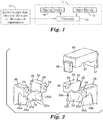
- FIGS. 4 - 6 illustrate custom tool 10.
- Custom tool 10 is substantially similar to the custom tool of FIGS. 2 and 3 except that occlusal portion 50 includes a hinged connection to lingual portion 30 rather than a slidable connection.
- occlusal portion 50 includes a hinged connection to lingual portion 30 rather than a slidable connection.
- features already discussed with respect to the custom tool of FIGS. 2 and 3 are not repeated in detail with respect to custom tool 10.
- FIGS. 4 - 6 further illustrate custom tool 10 in combination with teeth 100, 106, 108 within the mouth of a patient.
- the mouth of the patient further includes gingiva 110.
- Tooth 100 includes crown 102 with cavity 104.
- cavity 104 may have been a carious lesion in tooth 100 previously prepared by drilling or other preparation to remove damaged dental material.
- Facial portion 12 encompasses facial surface 116 of tooth 100, whereas lingual portion 30 encompasses lingual surface 118 of tooth 100.
- Custom tool 10 facilities dental restoration of tooth 100 including restoration surrounding cavity 104.
- Custom tool 10 may be formed based on a digital model of the teeth and mouth of a patient, which can be produced an intra-oral 3D scan, such as a multi-channel scanner (e.g., TRUE DEFINITION SCANNER, commercially available from 3M Company, Saint Paul, Minnesota).
- Methods of capturing the digital model dentition include, intraoral scanning or scanning a physical dental impression, or scan a model poured from a physical dental impression.
- the scan includes a target area of a tooth to be restored.
- the scan may additionally include one or more of the target area, complete tooth to be restored, adjacent teeth, surrounding soft tissue, opposing dentition and bite registration.
- Data may be captured during routine checkups, at the time a cavity is diagnosed, or during the restorative procedure.
- the captured data may by modified by trimming, error correction and hole filling. Additional dataset(s) such as opposing dention, 2D or 3D x-ray data of internal or subgingival features and non-patient specific standard root data may be used
- custom tool 10 may be digitally designed using CAD software, such as solid modeling software based on the digital model.
- CAD software such as Solid modeling software based on the digital model.
- fixed, parametric, or libraries of tool blank forms may be created in CAD software (e.g. Solidworks, NX /Unigraphics, ProEngineer, etc). These objects are typically exported into a separate 3D virtual work environment capable of managing point cloud or triangular mesh data and capable to performing Boolean operations (e.g. Materialise Magics, SpaceClaim).
- the standard forms are scaled to assure a proper fit between the standard part and the patients' dentition. The patient data may then be subtracted from the standard form.
- the tool design may be cut from a virtual shell built onto the target tooth structure.
- Custom tool 10 was designed to fit over tooth 100, the tooth to be restored (a first molar), as well as a portions of the adjacent teeth 106, 108.
- the shape of occlusal surface 52 may correspond to the shape of crown 102 prior to the preparation of cavity 104. In some other examples, the shape of occlusal surface 52 may correspond to the contact surfaces of the opposing tooth to identify missing tooth structure corresponding to cavity 104 of crown 102. In other examples, the shape of occlusal surface 52 may be derived from a projected shape by smoothing or flattening the digital model of the surface adjacent to cavity 104.
- the occlusal surface may be derived from occlusal surfaces not subject to the restoration (e.g., using the mirror image occlusal surface of the other first molar in the same arch or designing on the basis of opposing dentition).
- the occlusal surface may be constructed to achieve desired therapeutic benefit, such as opening of the bite, or to optimize occlusion.
- Software useful in such design include Lava Design from 3M Company, Saint Paul, Minnesota, 3Shape CAD Design, available from 3Shape of Copenhagen, Denmark, or exocad, available from exocad GMBH of Darmstadt, Germany.
- a virtual mold block may be created over the digital model and segmented into the mold components, in this example, facial portion 12, lingual portion 30 and occlusal portion 50.
- the precise location of one or more elements of custom tool 10 may be selected on the basis of the digital model to, e.g., facilitate assembly of the components within the mouth of the patient and/or to ensure access to a mold cavity with an injection port or a vent.
- Such customly-located elements may include a parting line, an injection port, a vent, a gate, and/or a boundary line between components. In this manner, the mold components facilitate eventual assembly of custom tool 10 on tooth 100 without geometric interference.
- the design of tool 10 may optionally be tested and/or optimized in a virtual environment that simulates its function in the mouth, such as a virtual articulator.
- the mold tool or form is segmented along parting lines to relieve undercuts where material compliance is insufficient for release, or to define volumes for the creation of varying material property transitions or gradients.
- occlusal portion 50 is attached to lingual portion 30 via a hinged connection.
- occlusal portion 50 was configured to be slideably received by facial portion 12 and lingual portion 30.
- the components within the CAD software may be converted into a 3D point mesh file or other format to facilitate production with a 3D printer, CNC mill or otherwise.
- the tool designs are then exported to a device capable of fabricating 3D objects, such as a CNC mill or a wide range of additive manufacturing / 3D printing equipment. Parts may be treated with agents to improve surface finish or release. The manufactured parts are then used in the dental procedure.
- the dental restorative material is provided in the dental capsule including a cannula adapter to fit with a port on the custom tool.
- the components of custom tool 10 were printed on an Object Conncx500 using VeroWhite, VcroBlack, Tango+, TangoBlack, as well as in metered blends of Vero White and Tango+.
- Objects could also optionally be printed using VeroClear, or on a 3D Systems SLA Viper si 2 using Accura 60 or Clearview.
- VeroBlack represents a rigid material and TangoBlack an elastomeric material, both of which block actinic radiation.
- Accura 60, Veroclear, and VeroWhite represent rigid materials, and Tango+ an elastomeric material, all of which transmit actinic radiation.
- Tango+ can also be blended with rigid "Vero family" materials to achieve intermediate durometers. The deformability of the elastomeric materials allows for improved compliance as well as improved release mechanics.
- the material may optionally be selected to facilitate curing of a dental restoration material within a mold cavity of the custom tool 10.
- Production may optionally include other steps such as, curing, e.g., in a UV chamber, cleaning, e.g., in alcohol solution, polishing, coating and/or assembly of various components, such as assembly of the hinged portion of occlusal portion 50 to lingual portion 30.
- the printed custom tool 10 can be pressed into uncured dental restorative material to form occlusal anatomy.
- Optionally engineered fracture lines may be included in custom tool 10 to help facilitate removal of custom tool 10 from the mouth of the patient.
- the completed tool 10 may be used to perform dental restoration of tooth 100 including restoration of cavity 104.
- lingual portion 30 and the facial (buccal) portion 12 may be within the mouth of a patient such that these components encompassed the tooth 100 isolate, separate or retract oral tissue, although tool 100 may optionally be place in combination with other equipment such as a matrix band.
- cavity 104 may be filled with a dental restorative material, such as, FILTEK Supreme Ultra Universal Restorative, available from 3M of Saint Paul, Minnesota, with an amount slightly exceeding the cavity volume of cavity 104.
- Occlusal portion 50 may be closed via rotation about the hinge and fully seated, thus transferring the details of occlusal surface 52 to the dental restorative material 105 ( FIG. 6 ) within cavity 104. In this manner, occlusal surface 52 of occlusal portion 50 combines with tooth 100 to form a mold cavity encompassing missing tooth structure (corresponding to cavity 104) of tooth 100.
- Excess restorative dental material may be expressed through the parting lines of the tool components upon the closure of the hinge.
- the dental restorative material may be light cured through the tool, such as with an XL 3000 curing light.
- tool 10 may be formed from a material transmissive to actinic radiation.
- molds may be filled with freshly mixed chemically curing dental restorative materials, such as 3M Concise Composite Restorative or 3M Ketac Molar glass ionomer filling material, following by sufficient incubation time in the mold to allow complete curing.
- the tool components may be removed from the mouth of a patient, and flashed (excess) restorative dental material may be removed with a dental scaler.
- the restored tooth 100 thus possesses an occlusal surface corresponding to that of occlusal surface 52 of occlusal portion 50. In this manner, intricate surfaces may be easily formed during repair of crown 102 of tooth 100.
- facial portion 12, lingual portion 30 and occlusal portion 50 may be designed in such a way that their placement forces separation of teeth 100, 106 and/or 108.
- facial portion 12, lingual portion 30 and occlusal portion 50 may be designed to precisely coincide with the geometries of teeth 100, 106, 108, except that the interproximal extensions of gingival surfaces 22a and 22b ( FIG. 6 ) of facial portion 12 and lingual portion 30 may be slightly wider than the spaces between teeth 100 and 106 and between teeth 100 and 108.
- the interproximal extensions of gingival surfaces 22a and 22b FIG.
- facial portion 12 and lingual portion 30 may be enlarged in the mesial and distal directions such that placement of facial portion 12 and lingual portion 30 creates outward pressure on one of both of teeth 106, 108 and/or pressure on tooth 100. In this manner, installing facial portion 12 and lingual portion 30 over teeth 100, 106, 108 may force the separation the spaces between teeth 100 and 106 and between teeth 100 and 108.
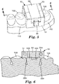
- FIGS. 7 - 10 illustrate custom tool 210 for forming a dental restoration in a mouth of a patient.
- Custom tool 210 includes a mold body with facial portion 212 and lingual portion 230. Facial portion 212 and lingual portion 230 snap-fit together and combine to define the surfaces of the desired tooth restoration.
- FIGS. 8 and 9 further illustrate custom tool 210 in combination with teeth 120, 126, 128 within the mouth of a patient.
- the mouth of the patient further includes gingiva 110.
- Tooth 120 includes a significant portion of missing tooth material, and may have been ground down to remove decayed material to facilitate dental restoration of the entire exposed surface of tooth 120.
- a 3D image of the mouth of the patient may be taken prior to the removal of decayed material from tooth 120 as the shape of the decayed material may help in the design of custom tool 210.
- the shape of the contralateral tooth may be mirrored in software, or a design created in a commercially available crown design software, such as 3Shape CAD Design, available from 3Shape of Copenhagen, Denmark, or exocad, available from exocad GMBH of Darmstadt, Germany.
- Facial portion 212 forms recesses 238 that are configured to receive protrusions 224 of lingual portion 230 to create the snap-fit connection between facial portion 212 and lingual portion 230.
- Facial portion 212 and lingual portion 230 are configured to surround a tooth of a patient.
- facial portion 212 forms customized facial surface 214 of the tooth
- lingual portion 230 forms customized lingual surface 232 of the tooth.
- Customized facial surface 214 and customized lingual surface 232 include customized proximal surfaces, corresponding to proximal surfaces of the tooth, as well as customized incisal surfaces, corresponding to incisal surfaces of the tooth.
- Facial portion 212 and lingual portion 230 also form customized gingival surfaces 222a and 222b, respectively, corresponding to gingival surfaces within the mouth of the patient.
- the mold body which includes, facial portion 212 and lingual portion 230 combines with tooth 120, to form a mold cavity.
- the mold cavity encompasses missing tooth structure of tooth 120.
- restorative dental material may be positioned into the mold and take the form of the missing tooth structure of tooth 120.
- restorative dental material may be placed on tooth 120 prior to assembling custom tool 210 over tooth 120.
- restorative dental material may be placed on surface 214 of facial portion 212 and/or surface 232 of lingual portion 230 tooth 120 prior to assembling custom tool 210 over tooth 120.
- custom tool 210 may be first assembled over tooth 120 and then restorative dental material may be injected into the mold cavity.
- one or both of facial portion 212 and lingual portion 230 may include a port configured to receive an injection of restorative dental material once custom tool 210 is positioned over tooth 120 to form the mold cavity.
- Facial portion 212 and lingual portion 230 are also each configured to register with adjacent teeth within the mouth of the patient to facilitate precise placement within the mouth of the patient.
- facial portion 212 and lingual portion 230 form customized surfaces 240a and 240b, respectively, corresponding to the surfaces of the adjacent tooth 126.
- Facial portion 212 and lingual portion 230 also form customized surfaces 242a and 242b, respectively, corresponding to the surfaces of the adjacent tooth 128. In this manner, facial portion 212 and lingual portion 230 register with teeth 126, 128 to facilitate precise positioning of custom tool 210 within the mouth of the patient for reconstruction of tooth 120.
- Custom tool 210 facilitates the dental restoration of more than one tooth at the same time.
- tooth 126 also includes missing tooth material on the crown of tooth 126.
- Custom tool 210 facilities reconstruction of tooth 126 coincident with the reconstruction of tooth 120.
- Positioning custom tool 210 over tooth 120 and tooth 126 further forms a second mold cavity representing the missing tooth material on the crown of tooth 126.
- restorative dental material may be placed within the mold cavity adjacent to tooth 126 in order to facilitate the reconstruction of tooth 126.
- custom tool 210 may include a second port configured to receive an injection of restorative dental material once custom tool 210 is positioned over tooth 120 to form the mold cavity adjacent to tooth 126.
- FIG. 10 illustrates repaired tooth 121 and teeth 126, 128 within the mouth of a patient following the repair with custom tool 210.
- Custom tool 210 may be formed in a similar matter to that previously described with respect to custom tool 10. For brevity, aspects of the design and manufacture of custom tool 210 that are already described with respect to custom tool 10 are not repeated in detail.
- a crown preparation was cut on a patient requiring restoration of their lower right cuspid, tooth 120.
- the prepared crown and neighboring dentition was captured by a full arch digital impression.
- the digital impression was imported into CAD software and the image of the lower left cuspid was mirrored to form the target restoration shape for the lower right cuspid, tooth 120.
- the target restoration shape was virtually placed on the crown preparation in the software environment to form the target design for the restored arch.
- a mold form was digitally designed in software to encompass the lower right archform, including the lower right cuspid needing restoration, tooth 120, and the adjacent teeth 126, 128.
- An optional filling port was digitally subtracted from the cuspid section of the mold form, located in a section of the tooth to be filled in the restoration process.
- the filling port was located in facial portion 212 and was sized to receive a tip of a commercially available restorative dental material compule, to permit injection of the restorative dental material within the mold cavity for tooth 120.
- a parting line to split the mold form into the facial portion 212 (labial) and lingual portion 230 was determined and alignment features 224, 238 were placed on the two portions 212, 230 to facilitate precise and secure assembly of the physical tool components during the later process of restoring the tooth.
- the components within the CAD software representing facial portion 212 and lingual portion 230, may be converted into a 3D point mesh file or other format to facilitate production with a 3D printer, CNC mill, or otherwise.
- Production may optionally include other steps such as, curing (e.g., in a UV chamber), cleaning, e.g., in alcohol solution.
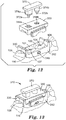
- FIGS. 11 - 14 illustrate custom tool 310 for forming a dental restorations of two adjacent teeth 100, 101 in a mouth of a patient with a mold body.
- the mold body includes lingual portion 312 and facial portion 330 that snap-fit together and a slidable occlusal portion 350.
- Slidable occlusal portion 350 includes injection ports 354a, 354b for delivery of dental restorative material to the mold cavities of custom tool 310, which correspond to teeth 100, 101.
- FIGS. 12 and 13 further illustrate custom tool 310 in combination with teeth 100, 101, 106, 108 within the mouth of a patient.
- the mouth of the patient further includes gingiva 110.
- Tooth 100 includes cavity 104 in the crown of tooth 100
- tooth 101 includes cavity 107 in the crown of tooth 101.
- cavities 104, 107 may have been caries previously prepared by drilling or other preparation to remove damaged dental material to facilitate dental restoration using tool 310.
- a 3D image of the mouth of the patient may be taken prior to the removal of decayed material from teeth 100, 101 as the shape of the decayed material may help in the design of custom tool 310.
- Lingual portion 312 and facial portion 330 are configured to surround teeth 100, 101.
- lingual portion 312 forms customized lingual surfaces 314, 315
- facial portion 330 forms customized facial surfaces 332, 333.
- customized lingual surfaces 314, 315 and customized facial surfaces 332, 333 include customized proximal surfaces, corresponding to proximal surfaces of teeth 100, 101.
- Lingual portion 312 and facial portion 330 also form customized gingival surfaces 322a and 322b, respectively, corresponding to gingival surfaces within the mouth of the patient.
- lingual portion 312 and facial portion 330 may be further configured to provide features, including customized gingival surfaces 322a and 322b representing an isolation matrix for a dental restoration.
- lingual portion 312 and facial portion 330 may contain features that extend subgingivally or into hidden interproximal space.
- the data for these extensions can be based off of anatomical averages, or patient x-ray data.
- the tool may incorporate elastomeric material which can be designed for an undersized fit to create a tight seal against varying actual geometry of the patient's dentition.
- the materials used may also vary in hydrophillicity to draw water, saliva, and other fluids away from the tooth structure being restored. Microfluidic channels, vacuum line attachments and bite blocks can be incorporated as well.
- Occlusal portion 350 provides customized occlusal surfaces 352, corresponding to occlusal surfaces of teeth 100, 101.
- Lingual portion 312 and facial portion 330 configured to accept slidable occlusal portion 350 of the mold body.
- Lingual portion 312, facial portion 330 and occlusal portion 350 are also configured to register with adjacent teeth 106, 108 within the mouth of the patient to facilitate precise placement within the mouth of the patient.
- lingual portion 312, facial portion 330 and occlusal portion 350 form customized mesial proximal surfaces 340a, 340b, 340c respectively, corresponding to mesial surfaces of the distally adjacent tooth 108.
- Lingual portion 312, facial portion 330 and occlusal portion 350 also form customized distal proximal surfaces 342a, 342b, (distal proximal surface of occlusal portion 350 not shown), respectively, corresponding to distal surfaces of the mesially adjacent tooth 106.
- the mold body which includes, lingual portion 312, facial portion 330 and occlusal portion 350 combines with teeth 100, 101 to form two distinct mold cavities.
- the mold cavities encompass missing tooth structure of teeth 100, 101.
- restorative dental material may be positioned into the mold cavities and take the form of the missing tooth structure of cavities 104, 107.
- occlusal portion 350 includes ports 354a, 354b configured to accept injection of a restorative dental material for the mold cavities corresponding to teeth 101, 100, respectively.
- press 370 may be positioned such that plugs 374a, 374b fill ports 354a, 354b, respectively.
- Plugs 374a, 374b further includes bottom surfaces 372a, 372b providing defined shapes corresponding to the occlusal surfaces of repaired teeth 101, 100.
- Plugs 374a, 374b have dissimilar shapes (square, round) to prevent misalignment of press 370 relative to occlusal portion 350.
- Occlusal portion 350 further includes vent holes 355a, 355b to allow air and excess dental material to escape the mold cavities as material is injected via fill ports 354a, 354b and as press 370 is positioned such that such that plugs 374a, 374b fill ports 354a, 354b, respectively.
- FIG. 14 illustrates repaired teeth 101, 100 within the mouth of a patient following the repair with custom tool 310.
- Custom tool 310 may be formed in a similar matter to that previously described with respect to custom tool 10 and custom tool 210. For brevity, aspects of the design and manufacture of custom tool 310 that are already described with respect to custom tool 10 are not repeated in detail.
- Custom tool 310 may be formed based on a digital model of the teeth and mouth of a patient, which can be produced an intra-oral 3D scan, such as a multi-channel scanner.
- custom tool 310 may be digitally designed using CAD software, such as solid modeling software based on the digital model.
- Custom tool 310 was designed to fit over teeth 100, 101 (adjacent first and second molars) and a portion of the neighboring teeth 106, 108. Subsequently, the tooth structure of teeth 100, 101, 106, 108 may be digitally subtracted the from a mold block, as were filling and venting ports (354a, 354b, 355a, 355b).
- an inverse of the tooth structure may be inverted within software to define the mold block.
- the ports may be located in regions of the occlusal section which correspond to regions of the teeth which would ultimately be removed in the preparation process, e.g., adjacent to the mold cavities of teeth 100, 101.
- Filling ports 354a, 354b may be sized to receive a tip of a commercially available restorative dental material compule, to permit injection of the restorative dental material during filling.
- Vent ports 355a, 355b may be sized smaller in diameter than the filling ports.
- the mold block design may be segmented into three sections (lingual portion 312, facial portion 330 and occlusal portion 350) to facilitate eventual assembly of the tool components on the teeth without geometric interference.
- additional segments may be provided such that portions of the mold for teeth 100, 101 may be separated such that each of lingual portion 312, facial portion 330 and occlusal portion 350 are divided into two or more components.
- the occlusal section was designed into the mold block such that it was bounded on the mesial and distal sides to assist with alignment of the occlusal section on the facial (buccal)-lingual assembly.
- Handle features (318) may be included added to lingual portion 312 and facial portion 330 to facilitate holding of the portions with a hemostat or cotton pliers during placement of the tool.
- the occlusal section may include tabs or sliders on the lingual and facial (buccal) side to provide precise alignment to the lingual and labial sections.
- An additional piece, a handle section, was designed to mate with the occlusal section as well as plug the filling ports 354a, 354b, in such a manner that the plug tips surfaces 372a, 372b, may be at, or slightly occlusal to, the desired occlusal surface of the restoration of teeth 100, 101.
- the components within the CAD software may be converted into a 3D point mesh file or other format to facilitate production with a 3D printer, CNC mill, or otherwise.
- Orientation marks e.g., a colored mark on the distal ends of each tool component
- Production may optionally include other steps such as, curing (e.g., in a UV oven), cleaning, e.g., in alcohol solution, and/or assembly of various components, polishing of tooth surfaces, coating, such as with a clear acrylic to enhance visibility of the restoration area during injection of the restorative dental material.
- surfaces of tool components expected to be in contact with the restorative dental material could optionally be coated with a layer of release agent (e.g., a thin layer of petroleum jelly).
- An example restoration process for teeth 100, 101 using custom tool 310 is described as follows. Matrix bands were trimmed so that their occlusal-gingival heights would be slightly above the height of the facial (buccal) and lingual portions after placement. The matrix bands were placed in the interproximal space where tooth structure of the first and second molars, teeth 100, 101, had been removed. The lingual portion 312 and facial portion 330 were assembled over teeth 100, 101 to assist with isolation and to secure the matrix bands in the proper positions (and to aid in adapting the shape of the matrix bands to the contours of the teeth 100, 101).
- a base layer of restorative dental material can optionally be layered into the deep portions of the preparation and dental restorative material photocured with an XL 3000 curing light.
- the occlusal portion 350 may be placed prior to adding a final increment of restorative dental material via ports 354a, 354b.
- the final increment of restorative dental material was then formed to the desired anatomy by injecting the restorative dental material via compule tip through the filling ports 354a, 354b while visually monitoring the filling process through the tool and at the vent ports 355a, 355b. After filling, the removable press 370 was mated with occlusal portion 350.
- the final increment of restorative dental material for both teeth 100, 101 may be photocured through tool 310, with the occlusal portion 350 and the removable press 370 in place. After curing, tool 310 was removed from the mouth of the patient and matrix bands removed to provide a shaped restoration including well-formed contacts. If needed, flashed (excess) restorative dental material may be removed, for example, with a dental scalar.
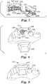
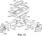
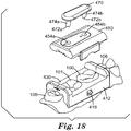
- FIGS. 15 - 18 illustrate custom tool 410 for forming a dental restorations of two adjacent teeth 100, 101 in a mouth of a patient configured to provide separation of adjacent teeth 100, 101, 106, 108 during restoration.
- Custom tool 410 includes a mold body with facial portion 430 and lingual portion 412 that snap-fit together and a slidable occlusal portion 450.
- Slidable occlusal portion 450 includes injection ports 454a, 454b for delivery of dental restorative material to the mold cavities of custom tool 410, which correspond to teeth 100, 101.
- Custom tool 410 is substantially similar to custom tool 310 with the exception that the geometries of lingual portion 312, facial portion 330 and occlusal portion 350 have been designed to provide separation of adjacent teeth 100, 101, 106, 108 during restoration rather than to exactly conform to the positions of teeth 100, 101, 106, 108 within the mouth of the patient. In this manner, custom tool 410 may facilitate separation of teeth without the use of separate matrix bands or wedges as described with respect to custom tool 310 or as typically practiced in the conventional direct restorative process.
- FIGS. 16 and 17 further illustrate custom tool 410 in combination with teeth 100, 101, 106, 108 within the mouth of a patient.
- the mouth of the patient further includes gingiva 110.
- Tooth 100 includes cavity 104 in the crown of tooth 100
- tooth 101 includes cavity 107 in the crown of tooth 101.
- cavities 104, 107 may have been caries previously prepared by drilling or other preparation to remove damaged dental material to facilitate dental restoration using tool 410.
- a 3D image of the mouth of the patient may be taken prior to the removal of decayed material from teeth 100, 101 as the shape of the decayed material may help in the design of custom tool 410.
- Lingual portion 412 and facial portion 430 are configured to surround teeth 100, 101.
- lingual portion 412 forms customized lingual surfaces 414, 415
- facial portion 430 forms customized facial surfaces 432, 433.
- customized lingual surfaces 414, 415 and customized facial surfaces 432, 433 include customized proximal surfaces, corresponding to proximal surfaces of teeth 100, 101.
- Lingual portion 412 and facial portion 430 also form customized gingival surfaces 422a and 422b, respectively, corresponding to gingival surfaces within the mouth of the patient.
- lingual portion 412 and facial portion 430 may be further configured to provide features, including customized gingival surfaces 422a and 422b representing an isolation matrix for a dental restoration.
- lingual portion 412 and facial portion 430 may contain features that extend subgingivally or into hidden interproximal space.
- the data for these extensions can be based off of anatomical averages, or patient x-ray data.
- An elastomeric component can be designed for an undersized fit to create a tight seal against varying actual geometry of the patient's dentition.
- the materials used may also vary in hydrophillicity to draw water and saliva away from the tooth structure being restored. Microfluidic channels, vacuum line attachments and bite blocks can be incorporated as well.
- Occlusal portion 450 provides customized occlusal surfaces 452, corresponding to occlusal surfaces of teeth 100, 101.
- Lingual portion 412 and facial portion 430 configured to accept slidable occlusal portion 450 of the mold body.
- Lingual portion 412, facial portion 430 and occlusal portion 450 are also configured to register with adjacent teeth 106, 108 within the mouth of the patient to facilitate precise placement within the mouth of the patient.
- lingual portion 412, facial portion 430 and occlusal portion 450 form customized mesial proximal surfaces 440a, 440b, 440c respectively, corresponding to mesial surfaces of the distally adjacent tooth 108.
- Lingual portion 412, facial portion 430 and occlusal portion 450 also form customized distal proximal surfaces 442a, 442b, (distal proximal surface of occlusal portion 450 not shown), respectively, corresponding to distal surfaces of the mesially adjacent tooth 106.
- the mold body which includes, lingual portion 412, facial portion 430 and occlusal portion 450 combines with teeth 100, 101 to form two distinct mold cavities.
- the mold cavities encompass missing tooth structure of teeth 100, 101.
- restorative dental material may be positioned into the mold cavities and take the form of the missing tooth structure of cavities 104, 107.
- occlusal portion 450 includes ports 454a, 454b configured to accept injection of a restorative dental material for the mold cavities corresponding to teeth 101, 100, respectively.
- press 470 may be positioned such that plugs 474a, 474b fill ports 454a, 454b, respectively.
- Plugs 474a, 474b further includes bottom surfaces 472a, 472b providing defined shapes corresponding to the occlusal surfaces of repaired teeth 101, 100.
- Occlusal portion 450 further includes vent holes 455a, 455b to allow air and excess dental material to escape the mold cavities as material is injected via fill ports 454a, 454b and as press 470 is positioned such that such that plugs 474a, 474b fill ports 454a, 454b, respectively.
- FIG. 18 illustrates repaired teeth 101, 100 within the mouth of a patient following the repair with custom tool 410.
- Custom tool 410 may be formed in a similar matter to that previously described with respect to custom tool 10 and custom tool 210. For brevity, aspects of the design and manufacture of custom tool 410 that are already described with respect to custom tool 10 and custom tool 210 are not repeated in detail.
- Custom tool 410 may be formed based on a digital model of the teeth and mouth of a patient, which can be produced an intra-oral 3D scan, such as a multi-channel scanner.
- custom tool 410 may be digitally designed using CAD software, such as solid modeling software based on the digital model.
- Custom tool 410 was designed to fit over teeth 100, 101 (adjacent first and second molars) and a portion of the neighboring teeth 106, 108.
- the CAD model of the scan for custom tool 410 was digitally segmented at the proximal planes to be restored and the resulting segments were each translated 100 microns to produce a gap between contacts of teeth 100, 101, 106 and 108.
- the tooth structure of teeth 100, 101, 106, 108 may be digitally subtracted the from a mold block, as were filling and venting ports (454a, 454b, 455a, 455b)
- the ports may be located in regions of the occlusal section which correspond to regions of the teeth which would ultimately be removed in the preparation process, e.g., adjacent to the cavities of teeth 100, 101.
- Filling ports 454a, 454b may be sized to receive a tip of a commercially available restorative dental material compule, to permit injection of the restorative dental material during filling.
- Vent ports 455a, 455b may be sized smaller in diameter than the filling ports.
- the mold block design may be segmented into three sections (lingual portion 412, facial portion 430 and occlusal portion 450) to facilitate eventual assembly of the tool components on the teeth.
- the parting line of lingual portion 412 and facial portion 430 in the interproximal regions was designed at an angle to the arch line. This provides that when the "wedge" portions came in contact, they would be overlapping at the contact area, reducing the risk of material flash during filling.
- the interproximal "wedge" portions of lingual portion 412 and facial portion 430 were digitally extended to create an interference of 500 microns.
- the occlusal section was designed into the mold block such that it was bounded on the mesial and distal sides to assist with alignment of the occlusal section on the facial (buccal)-lingual assembly.
- Handle features (418) may be included added to lingual portion 412 and facial portion 430 to facilitate holding of the portions with a hemostat or cotton pliers during placement of the tool.
- the occlusal section may include tabs or sliders on the lingual and facial (buccal) side to provide precise alignment to the lingual and labial sections.
- An additional piece, a handle section, was designed to mate with the occlusal section as well as plug the filling ports 454a, 454b, in such a manner that the plug tips surfaces 472a, 472b, may be at, or slightly occlusal to, the desired occlusal surface of the restoration of teeth 100, 101.
- the components within the CAD software may be converted into a 3D point mesh file or other format to facilitate production with a 3D printer, CNC mill or otherwise.
- Orientation marks i.e. a colored mark on the distal ends of each tool component
- Production may optionally include other steps such as, curing, e.g., in a UV chamber, cleaning, e.g., in alcohol solution, and/or assembly of various components, polishing of tooth surfaces, coating, such as with a clear acrylic to enhance visibility of the restoration area during injection of the restorative dental material.
- surfaces of tool components expected to be in contact with the restorative dental material could optionally be coated with a layer of release agent (e.g., a thin layer of petroleum jelly).
- An example restoration process for teeth 100, 101 using custom tool 410 is described as follows.
- the lingual portion 412 and facial portion 430 were assembled over teeth 100, 101 to assist with isolation, to slightly separate the teeth, and to create a matrix between the teeth.
- a base layer of restorative dental material can optionally be layered into the deep portions of the preparation and dental restorative material photocured with an XL 3000 curing light.
- the occlusal portion 450 may be placed prior to adding a final increment of restorative dental material via ports 454a, 454b.
- the final increment of restorative dental material was then formed to the desired anatomy by injecting the restorative dental material via compule tip through the filling ports 454a, 454b while visually monitoring the filling process through the tool and at the vent ports 455a, 455b.
- the removable press 470 was mated with occlusal portion 450.
- the final increment of restorative dental material for both teeth 100, 101 may be photocured through tool 410, with the occlusal portion 450 and the removable press 470 in place.
- tool 410 was removed from the mouth of the patient and matrix bands removed to provide a shaped restoration including well-formed contacts. If needed, flashed (excess) restorative dental material may be removed, for example, with a dental scalar.
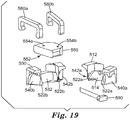
- FIGS. 19 - 22 illustrate custom tool 510 for forming a dental restoration in a mouth of a patient with a mold body including facial portion 530, clamps 580a, 580b that hold the lingual and facial portions together, a slidable occlusal portion 550 and a wedge 590 to facilitate separation of adjacent teeth during restoration.
- FIGS. 20 and 21 further illustrate custom tool 510 in combination with teeth 100, 106, 108 within the mouth of a patient.
- Tooth 100 includes cavity 104 in the crown of tooth 100. As shown, cavity 104 may have been a carious lesion in tooth 100 previously prepared by drilling or other preparation to remove damaged dental material to facilitate dental restoration using tool 510.
- the mouth of the patient further includes gingiva 110.
- Lingual portion 512 is configured to be secured to facial portion 530 by way of clips 580a, 580b.
- Lingual portion 512 and facial portion 530 are configured to surround tooth 100 within the mouth of a patient.
- lingual portion 512 forms customized facial surface 514 of the tooth whereas facial portion 530 forms customized lingual surface 532 of the tooth.
- Customized lingual surface 514 and customized facial surface 532 include customized proximal surfaces, corresponding to proximal surfaces of tooth 100.
- Lingual portion 512 and facial portion 530 also form customized gingival surfaces 522a and 522b, respectively, corresponding to gingival surfaces 110 within the mouth of the patient.
- Occlusal portion 550 includes customized occlusal surface 552, corresponding to occlusal surfaces of tooth 100.
- the mold body which includes, lingual portion 512, facial portion 530 and occlusal portion 550 combines with tooth 100 to form a mold cavity.
- the mold cavity encompasses cavity 104 in the crown of tooth 100.
- restorative dental material may be positioned into the mold and take the form of the missing tooth structure of cavity 104.
- Lingual portion 512 and facial portion 530 are also configured to register with adjacent teeth 106, 108 within the mouth of the patient to facilitate precise placement within the mouth of the patient.
- lingual portion 512 and facial portion 530 form customized mesial proximal surfaces 540a and 540b, respectively, corresponding to mesial surfaces of the distally adjacent tooth 108.
- Lingual portion 512 and facial portion 530 also form customized distal proximal surfaces 542a and 542b, respectively, corresponding to distal surfaces of the mesially adjacent tooth 106.
- FIG. 22 illustrates repaired tooth 100 as well as tooth 101 within the mouth of a patient following the repair with custom tool 510.
- Custom tool 510 may be formed based on a digital model of the teeth and mouth of a patient, which can be produced an intra-oral 3D scan, such as a multi-channel scanner.
- custom tool 510 may be digitally designed using CAD software, such as solid modeling software based on the digital model.
- Custom tool 510 was designed to fit over tooth 100, the tooth to be restored (a first molar), as well as a portions of the adjacent teeth 106, 108.
- a virtual mold block may be created over the digital model and segmented into the mold components, in this example, lingual portion 512, facial portion 530 and occlusal portion 550.
- the components within the CAD software may be converted into a 3D point mesh file or other format to facilitate production with a 3D printer, CNC mill or otherwise. Production may optionally include other steps such as, curing, cleaning, polishing, and/or coating with a clear coat and/or release agent as described previously.
- the completed tool 510 may be used to perform dental restoration of tooth 100.
- First a wedge 590 may be inserted in a custom channel to create space between teeth 100, 106 and/or teeth 100, 108, and optionally to help seal the gingival portion of the matrix.
- the custom design of tool 510 allows for the space creation and sealing aspects to be controlled independently.
- lingual portion 512 and facial portion 530 may be designed with a custom shaped slot that allows a foil or plastic matrix to be inserted from the occlusal to assure a custom shape and flash-free contact point between 100, 106, 108.
- the base of the tooth cavity may optionally be coated with liner / adhesive and filled in increments to prevent layers exceeding the allowable thickness for the application of a dental restoration material.
- the last increment of material may either placed directly on the tooth, into the custom tool 510, or alternatively place injected into an entry port after custom 510 is positioned over tooth 100.
- the dental restoration material may then be cured. Removal of custom tool 510 can be facilitated by coating custom tool 510 with a release agent (e.g. petroleum jelly, alcohol, silicone, lecithin, etc) prior to placement, by fabricating key sections of the custom tool 510 from peelable or low surface energy materials and/or creating stress concentrators in custom tool 510 that allow it to be broken away.
- a release agent e.g. petroleum jelly, alcohol, silicone, lecithin, etc
- various materials e.g. shade, mechanical properties
- levels of the various materials are indicated on the custom tools with lines or multiple occlusal caps can be created which form or press each layer to its desired configuration. This features allows any practitioner to create dental restorations with engineered layers for improved appearance and/or function.
- the restoration design has been modified form the initial scan data such that some surfaces of the optimized design are positioned below the uncut tooth surface. These positions are color coded in the custom tool to indicate to that user at try-in that these areas must be excavated prior to filling the tooth.
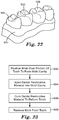
- FIG. 23 is a flowchart illustrating an example technique for forming a dental restoration in a mouth of a patient.
- a practitioner positions a mold, such as mold 10, 210, 310, 410 or 510, over a portion of a tooth of the patient (602).
- the mold combines with the tooth to form a mold cavity encompassing missing tooth structure of the tooth.
- a practitioner injects a dental restorative material within the mold cavity (604).
- the practitioner allows the dental restorative material to cure within the mold cavity to reform the tooth, which may include application of actinic radiation to cure the dental restorative material (606).
- the practitioner removes the mold from the tooth of the patient leaving the dental restoration with a shape defined by the mold cavity on the tooth of the patient (608).
- custom tools can be fabricated off of initial tooth geometry or digitally optimized tooth geometry (e.g. pulling and scaling data from tooth libraries, testing in a virtual articulator).
- Tools can be printed or milled.
- Tools can be made from the full range of 3D printed materials (strength, flexibility, translucency, color).
- Tools can contain features to indicate or define fill level of different restorative materials (shade, fill level, physical properties).
- Tools / mold sections can interlock with each other or with standard components (e.g. matrix bands). Tools can be used inside or outside of the mouth.
- Tools can be degradable (e.g.
- Kits can be created of the patient specific tools and associated products and quantities, (e.g. adhesives, filling, and polishing materials selected for the patient needs and/or doctor preferences). Series of tools used sequentially in the direct filling process in order to control the geometries of multiple layers of a dental restoration on a tooth.
- Dental scans may be taken at diagnostic appointment to facilitate custom tools fabrication prior to a filling appointment. Tools may be manufactured locally or digital scan data may be sent to a remote location for production.
Abstract
Description
- This disclosure relates to dental restorations.
- A dental restoration, or a dental filling, utilizes a dental restorative material used to improve function, integrity and morphology of missing or irregular tooth structure. For example, a dental restoration may be used to restore missing tooth structure following external trauma or as part of a restorative treatment for dental caries, or tooth decay.
- Restorative dentistry traditionally consists of drilling decay from an infected tooth (commonly referred to as "preparing" the tooth) and then using simple tools and a high level of craftsmanship to isolate, retract, fill and contour the finished restoration. Quality isolation via a rubber dam is cumbersome and often skipped for less effective isolation via cotton roles - increasing the risk of contamination which reduces longevity of the restoration. Retraction of soft and hard tissue includes manipulation of cords, wedges and matrix bands, and imperfect technique may result in contamination, residual flash in proximal areas, and poorly adapted contacts.
- While 'bulk fill' restorative materials and high intensity curing lights facilitate relatively fast filling of deep cavities (e.g., 4-5 mm), many restorations are completed in a single shade as practitioners may be uncertain of the correct layering protocol for multiple shades or types of restorative material. Last, with little geometrical guidance available on a prepared tooth, creation of the final filling level and occlusal surface geometry may include overfilling with dental restorative material, followed by an iterative process of grinding and checking tooth contact and biting function on an anesthetized patient. This process may be the most time consuming for dental restorations and errors here may result in tooth sensitivity and return visits for adjustment.
- This disclosure relates to dental restoration techniques incorporating the molding of dental restorative material directly on a tooth located within the mouth of a patient. Disclosed techniques include methods for dental restoration, custom tools used for dental restoration and techniques for producing custom tools for dental restoration. Disclosed techniques include tools providing mold cavities customized for an individual patient. In some examples, such custom tools may be produced using 3D printing techniques.
- In one example, this disclosure is directed to a custom tool for forming a dental restoration in a mouth of a patient. The mold body provides for a customized fit with at least one tooth of the patient. The mold body includes a facial portion forming a facial surface corresponding with a facial surface of the tooth, and further includes a separate lingual portion forming a lingual surface corresponding with a lingual surface of the tooth. The mold body is configured to combine with the tooth of the patient to form a mold cavity encompassing missing tooth structure of the tooth.
- In a further example, this disclosure is directed to a kit including the custom tool and a dental restorative material.
- In another example, this disclosure is directed to a method for forming a dental restoration in a mouth of a patient comprising positioning a mold over a portion of a tooth of the patient. The mold combines with the tooth to form a mold cavity encompassing missing tooth structure of the tooth. The method further comprises injecting a dental restorative material within the mold cavity, allowing the dental restorative material to cure within the mold cavity to reform the tooth, and removing the mold from the tooth of the patient.
- In an additional example, this disclosure is directed to a method for forming a dental restoration in a mouth of a patient comprising placing dental restorative material onto a portion of a tooth of the patient and positioning a mold over the portion of the tooth. The mold combines with the tooth to form a mold cavity encompassing missing tooth structure of the tooth. The method further includes allowing the dental restorative material to cure within the mold cavity to reform the tooth, and removing the mold from the tooth of the patient.
- In another example, this disclosure is directed to a process of making a custom tool for forming a dental restoration of a tooth within a mouth of a patient, the process comprising, obtaining three dimensional scan data of a patient's mouth, and three-dimensionally printing a custom tool for forming the dental restoration of the tooth based on the three dimensional scan data of the mouth of the patient. The custom tool is configured to combine with the tooth of the patient to form a mold cavity encompassing missing tooth structure of the tooth.
- The details of one or more examples of this disclosure are set forth in the accompanying drawings and the description below. Other features, objects, and advantages of this disclosure will be apparent from the description and drawings, and from the claims.
-
-
FIG. 1 is a diagram of a system for detecting and defining missing tooth structure using a digital 3D model based upon intra-oral scans, scans of impressions, or scans of models. -
FIGS. 2 and3 illustrate components of a custom tool for forming a dental restoration in a mouth of a patient with a mold body including a lingual portion and a facial portion that snap-fit together, and a slidable occlusal portion. -
FIGS. 4 - 6 illustrate a custom tool for forming a dental restoration in a mouth of a patient with a mold body including a lingual portion and a facial portion that snap-fit together, and a hinged occlusal portion. -
FIGS. 7 - 10 illustrate a custom tool for forming a dental restoration in a mouth of a patient with a mold body including a lingual portion and a facial portion that snap-fit together and combine to form an occlusal surface of the mold. -
FIGS. 11 - 14 illustrate a custom tool for forming a dental restorations of two adjacent teeth in a mouth of a patient with a mold body including a lingual portion and a facial portion that snap-fit together and a slidable occlusal portion, the slidable occlusal portion including injection ports for delivery of dental restorative material to the mold cavities of the custom tool. -
FIGS. 15 - 18 illustrate a custom tool for forming dental restorations of two adjacent teeth in a mouth of a patient configured to provide separation of adjacent teeth during restoration. -
FIGS. 19 - 22 illustrate a custom tool for forming a dental restoration in a mouth of a patient with a mold body including a lingual portion and a facial portion, clamps that hold the lingual and facial portions together, a slidable occlusal portion and a wedge to facilitate separation of adjacent teeth during restoration. -
FIG. 23 is a flowchart illustrating an example technique for forming a dental restoration in a mouth of a patient. - While conventional dental restoration techniques often include iterative steps and benefit from significant practitioner skill and experience, this disclosure includes techniques that may utilize custom molds to facilitate forming dental restorations within the mouth of a patient more precisely and quickly than generally possible using conventional dental restoration techniques.
- Disclosed techniques include capturing a three dimensional dentition of a patient with an intraoral scanner. The custom tool for a dental restoration may include a mold based on the three dimensional (3D) dentition of the patient. The disclosed techniques may facilitate high quality dental restorations with reduced time and skill requirements as compared to conventional dental restoration techniques.
-
FIG. 1 is a diagram of asystem 10 for detecting and defining tooth structure using a digital 3D model based upon intra-oral 3D scans or 3D scans of impressions or models of teeth.System 10 includes aprocessor 20 receiving digital 3D models of teeth (12) from intra-oral scans or scans of impressions of teeth.System 10 can also include anelectronic display device 16, such as a liquid crystal display (LCD) device, for displaying indications of changes in tooth shape and aninput device 18 for receiving user commands or other information. Systems to generate digital 3D images or models based upon image sets from multiple views are disclosed inU.S. Patent Nos. 7,956,862 and7,605,817 , both of which are incorporated by reference herein. These systems can use an intra-oral scanner to obtain digital images from multiple views of teeth or other intra-oral structures, and those digital images are processed to generate a digital 3D model representing the scanned teeth.System 10 can be implemented with, for example, a desktop, notebook, or tablet computer.System 10 can receive the 3D scans locally or remotely via a network, such a local area network (LAN) and/or the Internet. -
FIGS. 2 and3 illustrate components of a custom tool for forming a dental restoration in a mouth of a patient. The custom tool ofFIGS. 2 and3 comprises a mold body including alingual portion 30 andfacial portion 12 that snap-fit together, as well as slidableocclusal portion 50. More specifically,lingual portion 30forms recesses 38 that are configured to receiveprotrusions 24 offacial portion 12 to create the snap-fit connection betweenfacial portion 12 andlingual portion 30. In addition,facial portion 12 andlingual portion 30 may be further held together by slidableocclusal portion 50, includingtabs tab 56 and a hinge element (as shown inFIGS. 4 - 6 ). -
Facial portion 12 andlingual portion 30 are configured to surround a tooth of a patient. In particular,facial portion 12 forms customizedfacial surface 14 of the tooth whereaslingual portion 30 forms customizedlingual surface 32 of the tooth. In addition,facial portion 12 andlingual portion 30 form customizeddistal surfaces mesial surfaces occlusal portion 50 formsocclusal surface 52, corresponding to occlusal surfaces of the tooth.Facial portion 12 andlingual portion 30 also contain customizedgingival surfaces - The mold body, which includes,
facial portion 12,lingual portion 30 andocclusal portion 50 combines with the tooth, not shown, to form a mold cavity. The mold cavity encompasses missing tooth structure of the tooth, for example tooth structure removed when preparing a tooth to remove a carious lesion (or caries) to form cavity 104 (FIG. 4 ) suitable for receiving dental restorative material. By positioning the custom tool over the tooth, dental restorative material may be positioned into the mold to take the form of the missing tooth structure ofcavity 104 -
Facial portion 12 andlingual portion 30 each form portions oftop surface 26 of the custom tool as well as insideside surface 28 and inside receivingsurface 25, which are configured to accept slidableocclusal portion 50 of the mold body.Occlusal portion 50forms bottom surface 58, which is configured to register with inside receivingsurface 25.Occlusal portion 50further forms tab 56, which is configured to register withouter surface 16 offacial portion 12 , andtab 57, which is configured to register withouter surface 34 oflingual portion 30.Occlusal portion 50, includingtabs facial portion 12 andlingual portion 30 together when surrounding the tooth of the patient. -
Facial portion 12 andlingual portion 30 are also configured to register with adjacent teeth within the mouth of the patient to facilitate precise placement within the mouth of the patient. In particular,facial portion 12 andlingual portion 30 form customizedmesial surfaces Facial portion 12 andlingual portion 30 also form customizeddistal surfaces -
FIGS. 4 - 6 illustratecustom tool 10.Custom tool 10 is substantially similar to the custom tool ofFIGS. 2 and3 except thatocclusal portion 50 includes a hinged connection tolingual portion 30 rather than a slidable connection. For brevity, features already discussed with respect to the custom tool ofFIGS. 2 and3 are not repeated in detail with respect tocustom tool 10. -
FIGS. 4 - 6 further illustratecustom tool 10 in combination withteeth gingiva 110.Tooth 100 includescrown 102 withcavity 104. As shown,cavity 104 may have been a carious lesion intooth 100 previously prepared by drilling or other preparation to remove damaged dental material.Facial portion 12 encompassesfacial surface 116 oftooth 100, whereaslingual portion 30 encompasseslingual surface 118 oftooth 100.Custom tool 10 facilities dental restoration oftooth 100 includingrestoration surrounding cavity 104. -
Custom tool 10 may be formed based on a digital model of the teeth and mouth of a patient, which can be produced an intra-oral 3D scan, such as a multi-channel scanner (e.g., TRUE DEFINITION SCANNER, commercially available from 3M Company, Saint Paul, Minnesota). Methods of capturing the digital model dentition include, intraoral scanning or scanning a physical dental impression, or scan a model poured from a physical dental impression. Minimally, the scan includes a target area of a tooth to be restored. The scan may additionally include one or more of the target area, complete tooth to be restored, adjacent teeth, surrounding soft tissue, opposing dentition and bite registration. Data may be captured during routine checkups, at the time a cavity is diagnosed, or during the restorative procedure. The captured data may by modified by trimming, error correction and hole filling. Additional dataset(s) such as opposing dention, 2D or 3D x-ray data of internal or subgingival features and non-patient specific standard root data may be used to augment the captured data. - In one particular example,
custom tool 10 may be digitally designed using CAD software, such as solid modeling software based on the digital model. For example, fixed, parametric, or libraries of tool blank forms may be created in CAD software (e.g. Solidworks, NX /Unigraphics, ProEngineer, etc). These objects are typically exported into a separate 3D virtual work environment capable of managing point cloud or triangular mesh data and capable to performing Boolean operations (e.g. Materialise Magics, SpaceClaim). Optionally, the standard forms are scaled to assure a proper fit between the standard part and the patients' dentition. The patient data may then be subtracted from the standard form. As an alternative approach to Boolean subtraction, the tool design may be cut from a virtual shell built onto the target tooth structure. -
Custom tool 10 was designed to fit overtooth 100, the tooth to be restored (a first molar), as well as a portions of theadjacent teeth occlusal surface 52 may correspond to the shape ofcrown 102 prior to the preparation ofcavity 104. In some other examples, the shape ofocclusal surface 52 may correspond to the contact surfaces of the opposing tooth to identify missing tooth structure corresponding tocavity 104 ofcrown 102. In other examples, the shape ofocclusal surface 52 may be derived from a projected shape by smoothing or flattening the digital model of the surface adjacent tocavity 104. Alternatively or additionally, the occlusal surface may be derived from occlusal surfaces not subject to the restoration (e.g., using the mirror image occlusal surface of the other first molar in the same arch or designing on the basis of opposing dentition). Alternatively or additionally, the occlusal surface may be constructed to achieve desired therapeutic benefit, such as opening of the bite, or to optimize occlusion. Software useful in such design include Lava Design from 3M Company, Saint Paul, Minnesota, 3Shape CAD Design, available from 3Shape of Copenhagen, Denmark, or exocad, available from exocad GMBH of Darmstadt, Germany. In any event, to design the components ofcustom tool 10, a virtual mold block may be created over the digital model and segmented into the mold components, in this example,facial portion 12,lingual portion 30 andocclusal portion 50. The precise location of one or more elements ofcustom tool 10 may be selected on the basis of the digital model to, e.g., facilitate assembly of the components within the mouth of the patient and/or to ensure access to a mold cavity with an injection port or a vent. Such customly-located elements may include a parting line, an injection port, a vent, a gate, and/or a boundary line between components. In this manner, the mold components facilitate eventual assembly ofcustom tool 10 ontooth 100 without geometric interference. - The design of
tool 10 may optionally be tested and/or optimized in a virtual environment that simulates its function in the mouth, such as a virtual articulator. The mold tool or form is segmented along parting lines to relieve undercuts where material compliance is insufficient for release, or to define volumes for the creation of varying material property transitions or gradients. - In the examples, of
FIGS. 4 - 6 occlusal portion 50 is attached tolingual portion 30 via a hinged connection. In contrast, inFIGS 2 and3 ,occlusal portion 50 was configured to be slideably received byfacial portion 12 andlingual portion 30. In any event, the components within the CAD software may be converted into a 3D point mesh file or other format to facilitate production with a 3D printer, CNC mill or otherwise. The tool designs are then exported to a device capable of fabricating 3D objects, such as a CNC mill or a wide range of additive manufacturing / 3D printing equipment. Parts may be treated with agents to improve surface finish or release. The manufactured parts are then used in the dental procedure. They may be printed locally or they may be sent as part of a procedure kit, which includes adhesives, dental restorative material and other consumables for the procedure. In some examples, the dental restorative material is provided in the dental capsule including a cannula adapter to fit with a port on the custom tool. - In some specific examples, the components of
custom tool 10, were printed on an Object Conncx500 using VeroWhite, VcroBlack, Tango+, TangoBlack, as well as in metered blends of Vero White and Tango+. Objects could also optionally be printed using VeroClear, or on a 3D Systems SLA Viper si2 using Accura 60 or Clearview. VeroBlack represents a rigid material and TangoBlack an elastomeric material, both of which block actinic radiation. Accura 60, Veroclear, and VeroWhite represent rigid materials, and Tango+ an elastomeric material, all of which transmit actinic radiation. Tango+ can also be blended with rigid "Vero family" materials to achieve intermediate durometers. The deformability of the elastomeric materials allows for improved compliance as well as improved release mechanics. The material may optionally be selected to facilitate curing of a dental restoration material within a mold cavity of thecustom tool 10. - Production may optionally include other steps such as, curing, e.g., in a UV chamber, cleaning, e.g., in alcohol solution, polishing, coating and/or assembly of various components, such as assembly of the hinged portion of
occlusal portion 50 tolingual portion 30. The printedcustom tool 10 can be pressed into uncured dental restorative material to form occlusal anatomy. Optionally engineered fracture lines may be included incustom tool 10 to help facilitate removal ofcustom tool 10 from the mouth of the patient. - The completed
tool 10 may be used to perform dental restoration oftooth 100 including restoration ofcavity 104. First,lingual portion 30 and the facial (buccal)portion 12 may be within the mouth of a patient such that these components encompassed thetooth 100 isolate, separate or retract oral tissue, althoughtool 100 may optionally be place in combination with other equipment such as a matrix band. In this example,cavity 104 may be filled with a dental restorative material, such as, FILTEK Supreme Ultra Universal Restorative, available from 3M of Saint Paul, Minnesota, with an amount slightly exceeding the cavity volume ofcavity 104.Occlusal portion 50 may be closed via rotation about the hinge and fully seated, thus transferring the details ofocclusal surface 52 to the dental restorative material 105 (FIG. 6 ) withincavity 104. In this manner,occlusal surface 52 ofocclusal portion 50 combines withtooth 100 to form a mold cavity encompassing missing tooth structure (corresponding to cavity 104) oftooth 100. - Excess restorative dental material may be expressed through the parting lines of the tool components upon the closure of the hinge. The dental restorative material may be light cured through the tool, such as with an XL 3000 curing light. For example,
tool 10 may be formed from a material transmissive to actinic radiation. Alternatively, molds may be filled with freshly mixed chemically curing dental restorative materials, such as 3M Concise Composite Restorative or 3M Ketac Molar glass ionomer filling material, following by sufficient incubation time in the mold to allow complete curing. After curing, the tool components may be removed from the mouth of a patient, and flashed (excess) restorative dental material may be removed with a dental scaler. The restoredtooth 100 thus possesses an occlusal surface corresponding to that ofocclusal surface 52 ofocclusal portion 50. In this manner, intricate surfaces may be easily formed during repair ofcrown 102 oftooth 100. - In some examples,
facial portion 12,lingual portion 30 andocclusal portion 50 may be designed in such a way that their placement forces separation ofteeth facial portion 12,lingual portion 30 andocclusal portion 50 may be designed to precisely coincide with the geometries ofteeth gingival surfaces FIG. 6 ) offacial portion 12 andlingual portion 30 may be slightly wider than the spaces betweenteeth teeth gingival surfaces FIG. 6 ) offacial portion 12 andlingual portion 30 may be enlarged in the mesial and distal directions such that placement offacial portion 12 andlingual portion 30 creates outward pressure on one of both ofteeth tooth 100. In this manner, installingfacial portion 12 andlingual portion 30 overteeth teeth teeth -
FIGS. 7 - 10 illustratecustom tool 210 for forming a dental restoration in a mouth of a patient.Custom tool 210 includes a mold body withfacial portion 212 andlingual portion 230.Facial portion 212 andlingual portion 230 snap-fit together and combine to define the surfaces of the desired tooth restoration.FIGS. 8 and 9 further illustratecustom tool 210 in combination withteeth gingiva 110.Tooth 120 includes a significant portion of missing tooth material, and may have been ground down to remove decayed material to facilitate dental restoration of the entire exposed surface oftooth 120. In some examples a 3D image of the mouth of the patient (or of a dental impression) may be taken prior to the removal of decayed material fromtooth 120 as the shape of the decayed material may help in the design ofcustom tool 210. In the same or different examples, the shape of the contralateral tooth may be mirrored in software, or a design created in a commercially available crown design software, such as 3Shape CAD Design, available from 3Shape of Copenhagen, Denmark, or exocad, available from exocad GMBH of Darmstadt, Germany. -
Facial portion 212 forms recesses 238 that are configured to receiveprotrusions 224 oflingual portion 230 to create the snap-fit connection betweenfacial portion 212 andlingual portion 230. -
Facial portion 212 andlingual portion 230 are configured to surround a tooth of a patient. In particular,facial portion 212 forms customizedfacial surface 214 of the tooth whereaslingual portion 230 forms customizedlingual surface 232 of the tooth. Customizedfacial surface 214 and customizedlingual surface 232 include customized proximal surfaces, corresponding to proximal surfaces of the tooth, as well as customized incisal surfaces, corresponding to incisal surfaces of the tooth.Facial portion 212 andlingual portion 230 also form customizedgingival surfaces - The mold body, which includes,
facial portion 212 andlingual portion 230 combines withtooth 120, to form a mold cavity. The mold cavity encompasses missing tooth structure oftooth 120. By positioningcustom tool 210 overtooth 120, restorative dental material may be positioned into the mold and take the form of the missing tooth structure oftooth 120. In some examples, restorative dental material may be placed ontooth 120 prior to assemblingcustom tool 210 overtooth 120. In the same or different examples, restorative dental material may be placed onsurface 214 offacial portion 212 and/orsurface 232 oflingual portion 230tooth 120 prior to assemblingcustom tool 210 overtooth 120. In another example,custom tool 210 may be first assembled overtooth 120 and then restorative dental material may be injected into the mold cavity. For example, one or both offacial portion 212 andlingual portion 230 may include a port configured to receive an injection of restorative dental material oncecustom tool 210 is positioned overtooth 120 to form the mold cavity. -
Facial portion 212 andlingual portion 230 are also each configured to register with adjacent teeth within the mouth of the patient to facilitate precise placement within the mouth of the patient. In particular,facial portion 212 andlingual portion 230 form customizedsurfaces adjacent tooth 126.Facial portion 212 andlingual portion 230 also form customizedsurfaces adjacent tooth 128. In this manner,facial portion 212 andlingual portion 230 register withteeth custom tool 210 within the mouth of the patient for reconstruction oftooth 120. -
Custom tool 210 facilitates the dental restoration of more than one tooth at the same time. As shown inFIG. 8 , liketooth 120,tooth 126 also includes missing tooth material on the crown oftooth 126.Custom tool 210 facilities reconstruction oftooth 126 coincident with the reconstruction oftooth 120. Positioningcustom tool 210 overtooth 120 andtooth 126 further forms a second mold cavity representing the missing tooth material on the crown oftooth 126. As described with respect totooth 120, restorative dental material may be placed within the mold cavity adjacent totooth 126 in order to facilitate the reconstruction oftooth 126. For example,custom tool 210 may include a second port configured to receive an injection of restorative dental material oncecustom tool 210 is positioned overtooth 120 to form the mold cavity adjacent totooth 126.FIG. 10 illustrates repairedtooth 121 andteeth custom tool 210. -
Custom tool 210 may be formed in a similar matter to that previously described with respect tocustom tool 10. For brevity, aspects of the design and manufacture ofcustom tool 210 that are already described with respect tocustom tool 10 are not repeated in detail. - A crown preparation was cut on a patient requiring restoration of their lower right cuspid,
tooth 120. The prepared crown and neighboring dentition was captured by a full arch digital impression. The digital impression was imported into CAD software and the image of the lower left cuspid was mirrored to form the target restoration shape for the lower right cuspid,tooth 120. The target restoration shape was virtually placed on the crown preparation in the software environment to form the target design for the restored arch. A mold form was digitally designed in software to encompass the lower right archform, including the lower right cuspid needing restoration,tooth 120, and theadjacent teeth facial portion 212 and was sized to receive a tip of a commercially available restorative dental material compule, to permit injection of the restorative dental material within the mold cavity fortooth 120. A parting line to split the mold form into the facial portion 212 (labial) andlingual portion 230 was determined and alignment features 224, 238 were placed on the twoportions - The components within the CAD software, representing
facial portion 212 andlingual portion 230, may be converted into a 3D point mesh file or other format to facilitate production with a 3D printer, CNC mill, or otherwise. Production may optionally include other steps such as, curing (e.g., in a UV chamber), cleaning, e.g., in alcohol solution. -
FIGS. 11 - 14 illustratecustom tool 310 for forming a dental restorations of twoadjacent teeth lingual portion 312 andfacial portion 330 that snap-fit together and a slidableocclusal portion 350. Slidableocclusal portion 350 includesinjection ports custom tool 310, which correspond toteeth -
FIGS. 12 and 13 further illustratecustom tool 310 in combination withteeth gingiva 110.Tooth 100 includescavity 104 in the crown oftooth 100, andtooth 101 includescavity 107 in the crown oftooth 101. As shown,cavities restoration using tool 310. In some examples a 3D image of the mouth of the patient may be taken prior to the removal of decayed material fromteeth custom tool 310. -
Lingual portion 312 andfacial portion 330 are configured to surroundteeth lingual portion 312 forms customizedlingual surfaces facial portion 330 forms customizedfacial surfaces lingual surfaces facial surfaces teeth Lingual portion 312 andfacial portion 330 also form customizedgingival surfaces - Optionally,
lingual portion 312 andfacial portion 330 may be further configured to provide features, including customizedgingival surfaces lingual portion 312 andfacial portion 330 may contain features that extend subgingivally or into hidden interproximal space. The data for these extensions can be based off of anatomical averages, or patient x-ray data. The tool may incorporate elastomeric material which can be designed for an undersized fit to create a tight seal against varying actual geometry of the patient's dentition. The materials used may also vary in hydrophillicity to draw water, saliva, and other fluids away from the tooth structure being restored. Microfluidic channels, vacuum line attachments and bite blocks can be incorporated as well. -
Occlusal portion 350 provides customizedocclusal surfaces 352, corresponding to occlusal surfaces ofteeth Lingual portion 312 andfacial portion 330 configured to accept slidableocclusal portion 350 of the mold body. -
Lingual portion 312,facial portion 330 andocclusal portion 350 are also configured to register withadjacent teeth lingual portion 312,facial portion 330 andocclusal portion 350 form customized mesialproximal surfaces adjacent tooth 108.Lingual portion 312,facial portion 330 andocclusal portion 350 also form customized distalproximal surfaces occlusal portion 350 not shown), respectively, corresponding to distal surfaces of the mesiallyadjacent tooth 106. - The mold body, which includes,
lingual portion 312,facial portion 330 andocclusal portion 350 combines withteeth teeth custom tool 310 overteeth cavities - In particular,
occlusal portion 350 includesports teeth custom tool 310,press 370 may be positioned such thatplugs ports Plugs bottom surfaces teeth Plugs press 370 relative toocclusal portion 350.Occlusal portion 350 further includesvent holes fill ports press 370 is positioned such that such thatplugs ports FIG. 14 illustrates repairedteeth custom tool 310. -
Custom tool 310 may be formed in a similar matter to that previously described with respect tocustom tool 10 andcustom tool 210. For brevity, aspects of the design and manufacture ofcustom tool 310 that are already described with respect tocustom tool 10 are not repeated in detail. -
Custom tool 310 may be formed based on a digital model of the teeth and mouth of a patient, which can be produced an intra-oral 3D scan, such as a multi-channel scanner. In one particular example,custom tool 310 may be digitally designed using CAD software, such as solid modeling software based on the digital model.Custom tool 310 was designed to fit overteeth 100, 101 (adjacent first and second molars) and a portion of the neighboringteeth teeth teeth ports Vent ports - The mold block design may be segmented into three sections (
lingual portion 312,facial portion 330 and occlusal portion 350) to facilitate eventual assembly of the tool components on the teeth without geometric interference. Alternatively, additional segments may be provided such that portions of the mold forteeth lingual portion 312,facial portion 330 andocclusal portion 350 are divided into two or more components. The occlusal section was designed into the mold block such that it was bounded on the mesial and distal sides to assist with alignment of the occlusal section on the facial (buccal)-lingual assembly. Handle features (318) may be included added tolingual portion 312 andfacial portion 330 to facilitate holding of the portions with a hemostat or cotton pliers during placement of the tool. - The occlusal section may include tabs or sliders on the lingual and facial (buccal) side to provide precise alignment to the lingual and labial sections. An additional piece, a handle section, was designed to mate with the occlusal section as well as plug the filling
ports plug tips surfaces teeth - The components within the CAD software may be converted into a 3D point mesh file or other format to facilitate production with a 3D printer, CNC mill, or otherwise. Orientation marks (e.g., a colored mark on the distal ends of each tool component) may be applied to the tool components to facilitate assembly. Production may optionally include other steps such as, curing (e.g., in a UV oven), cleaning, e.g., in alcohol solution, and/or assembly of various components, polishing of tooth surfaces, coating, such as with a clear acrylic to enhance visibility of the restoration area during injection of the restorative dental material. In addition, surfaces of tool components expected to be in contact with the restorative dental material could optionally be coated with a layer of release agent (e.g., a thin layer of petroleum jelly).
- An example restoration process for
teeth custom tool 310 is described as follows. Matrix bands were trimmed so that their occlusal-gingival heights would be slightly above the height of the facial (buccal) and lingual portions after placement. The matrix bands were placed in the interproximal space where tooth structure of the first and second molars,teeth lingual portion 312 andfacial portion 330 were assembled overteeth teeth 100, 101). Because the tooth preparations may prepared at a depth greater than the recommended maximum cure depth for the restorative dental material, a base layer of restorative dental material can optionally be layered into the deep portions of the preparation and dental restorative material photocured with an XL 3000 curing light. Theocclusal portion 350 may be placed prior to adding a final increment of restorative dental material viaports ports vent ports removable press 370 was mated withocclusal portion 350. The final increment of restorative dental material for bothteeth tool 310, with theocclusal portion 350 and theremovable press 370 in place. After curing,tool 310 was removed from the mouth of the patient and matrix bands removed to provide a shaped restoration including well-formed contacts. If needed, flashed (excess) restorative dental material may be removed, for example, with a dental scalar. -
FIGS. 15 - 18 illustratecustom tool 410 for forming a dental restorations of twoadjacent teeth adjacent teeth Custom tool 410 includes a mold body withfacial portion 430 andlingual portion 412 that snap-fit together and a slidableocclusal portion 450. Slidableocclusal portion 450 includesinjection ports custom tool 410, which correspond toteeth -
Custom tool 410 is substantially similar tocustom tool 310 with the exception that the geometries oflingual portion 312,facial portion 330 andocclusal portion 350 have been designed to provide separation ofadjacent teeth teeth custom tool 410 may facilitate separation of teeth without the use of separate matrix bands or wedges as described with respect tocustom tool 310 or as typically practiced in the conventional direct restorative process. -
FIGS. 16 and 17 further illustratecustom tool 410 in combination withteeth gingiva 110.Tooth 100 includescavity 104 in the crown oftooth 100, andtooth 101 includescavity 107 in the crown oftooth 101. As shown,cavities restoration using tool 410. In some examples a 3D image of the mouth of the patient may be taken prior to the removal of decayed material fromteeth custom tool 410. -
Lingual portion 412 andfacial portion 430 are configured to surroundteeth lingual portion 412 forms customizedlingual surfaces facial portion 430 forms customizedfacial surfaces lingual surfaces facial surfaces teeth Lingual portion 412 andfacial portion 430 also form customizedgingival surfaces - Optionally,
lingual portion 412 andfacial portion 430 may be further configured to provide features, including customizedgingival surfaces lingual portion 412 andfacial portion 430 may contain features that extend subgingivally or into hidden interproximal space. The data for these extensions can be based off of anatomical averages, or patient x-ray data. An elastomeric component can be designed for an undersized fit to create a tight seal against varying actual geometry of the patient's dentition. The materials used may also vary in hydrophillicity to draw water and saliva away from the tooth structure being restored. Microfluidic channels, vacuum line attachments and bite blocks can be incorporated as well. -
Occlusal portion 450 provides customized occlusal surfaces 452, corresponding to occlusal surfaces ofteeth Lingual portion 412 andfacial portion 430 configured to accept slidableocclusal portion 450 of the mold body. -
Lingual portion 412,facial portion 430 andocclusal portion 450 are also configured to register withadjacent teeth lingual portion 412,facial portion 430 andocclusal portion 450 form customized mesialproximal surfaces adjacent tooth 108.Lingual portion 412,facial portion 430 andocclusal portion 450 also form customized distalproximal surfaces occlusal portion 450 not shown), respectively, corresponding to distal surfaces of the mesiallyadjacent tooth 106. - The mold body, which includes,
lingual portion 412,facial portion 430 andocclusal portion 450 combines withteeth teeth custom tool 410 overteeth cavities - In particular,
occlusal portion 450 includesports teeth custom tool 410,press 470 may be positioned such thatplugs ports Plugs bottom surfaces teeth Occlusal portion 450 further includesvent holes fill ports press 470 is positioned such that such thatplugs ports FIG. 18 illustrates repairedteeth custom tool 410. -
Custom tool 410 may be formed in a similar matter to that previously described with respect tocustom tool 10 andcustom tool 210. For brevity, aspects of the design and manufacture ofcustom tool 410 that are already described with respect tocustom tool 10 andcustom tool 210 are not repeated in detail. -
Custom tool 410 may be formed based on a digital model of the teeth and mouth of a patient, which can be produced an intra-oral 3D scan, such as a multi-channel scanner. In one particular example,custom tool 410 may be digitally designed using CAD software, such as solid modeling software based on the digital model.Custom tool 410 was designed to fit overteeth 100, 101 (adjacent first and second molars) and a portion of the neighboringteeth custom tool 310, the CAD model of the scan forcustom tool 410 was digitally segmented at the proximal planes to be restored and the resulting segments were each translated 100 microns to produce a gap between contacts ofteeth teeth teeth ports Vent ports - The mold block design may be segmented into three sections (
lingual portion 412,facial portion 430 and occlusal portion 450) to facilitate eventual assembly of the tool components on the teeth. The parting line oflingual portion 412 andfacial portion 430 in the interproximal regions was designed at an angle to the arch line. This provides that when the "wedge" portions came in contact, they would be overlapping at the contact area, reducing the risk of material flash during filling. As a secondary measure, the interproximal "wedge" portions oflingual portion 412 andfacial portion 430 were digitally extended to create an interference of 500 microns. Due to the finite resolution of the printing device used for manufacturing, there can be a loss in feature fidelity as sizes reduce to zero (as is the case with a wedge, or knife edge). Extending the interproximal "wedge" components may compensate for this "under-printing" seen during physical production. - The occlusal section was designed into the mold block such that it was bounded on the mesial and distal sides to assist with alignment of the occlusal section on the facial (buccal)-lingual assembly. Handle features (418) may be included added to
lingual portion 412 andfacial portion 430 to facilitate holding of the portions with a hemostat or cotton pliers during placement of the tool. - The occlusal section may include tabs or sliders on the lingual and facial (buccal) side to provide precise alignment to the lingual and labial sections. An additional piece, a handle section, was designed to mate with the occlusal section as well as plug the filling
ports plug tips surfaces teeth - The components within the CAD software may be converted into a 3D point mesh file or other format to facilitate production with a 3D printer, CNC mill or otherwise. Orientation marks (i.e. a colored mark on the distal ends of each tool component) may be applied to the tool components to facilitate assembly. Production may optionally include other steps such as, curing, e.g., in a UV chamber, cleaning, e.g., in alcohol solution, and/or assembly of various components, polishing of tooth surfaces, coating, such as with a clear acrylic to enhance visibility of the restoration area during injection of the restorative dental material. In addition, surfaces of tool components expected to be in contact with the restorative dental material could optionally be coated with a layer of release agent (e.g., a thin layer of petroleum jelly).
- An example restoration process for
teeth custom tool 410 is described as follows. Thelingual portion 412 andfacial portion 430 were assembled overteeth occlusal portion 450 may be placed prior to adding a final increment of restorative dental material viaports ports vent ports removable press 470 was mated withocclusal portion 450. The final increment of restorative dental material for bothteeth tool 410, with theocclusal portion 450 and theremovable press 470 in place. After curing,tool 410 was removed from the mouth of the patient and matrix bands removed to provide a shaped restoration including well-formed contacts. If needed, flashed (excess) restorative dental material may be removed, for example, with a dental scalar. -
FIGS. 19 - 22 illustratecustom tool 510 for forming a dental restoration in a mouth of a patient with a mold body includingfacial portion 530, clamps 580a, 580b that hold the lingual and facial portions together, a slidableocclusal portion 550 and awedge 590 to facilitate separation of adjacent teeth during restoration.FIGS. 20 and 21 further illustratecustom tool 510 in combination withteeth Tooth 100 includescavity 104 in the crown oftooth 100. As shown,cavity 104 may have been a carious lesion intooth 100 previously prepared by drilling or other preparation to remove damaged dental material to facilitate dentalrestoration using tool 510. The mouth of the patient further includesgingiva 110.Lingual portion 512 is configured to be secured tofacial portion 530 by way ofclips Lingual portion 512 andfacial portion 530 are configured to surroundtooth 100 within the mouth of a patient. In particular,lingual portion 512 forms customizedfacial surface 514 of the tooth whereasfacial portion 530 forms customizedlingual surface 532 of the tooth. - Customized
lingual surface 514 and customizedfacial surface 532 include customized proximal surfaces, corresponding to proximal surfaces oftooth 100.Lingual portion 512 andfacial portion 530 also form customizedgingival surfaces gingival surfaces 110 within the mouth of the patient.Occlusal portion 550 includes customizedocclusal surface 552, corresponding to occlusal surfaces oftooth 100. - The mold body, which includes,
lingual portion 512,facial portion 530 andocclusal portion 550 combines withtooth 100 to form a mold cavity. The mold cavity encompassescavity 104 in the crown oftooth 100. By positioning thecustom tool 510 overtooth 100, restorative dental material may be positioned into the mold and take the form of the missing tooth structure ofcavity 104. -
Lingual portion 512 andfacial portion 530 are also configured to register withadjacent teeth lingual portion 512 andfacial portion 530 form customized mesialproximal surfaces adjacent tooth 108.Lingual portion 512 andfacial portion 530 also form customized distalproximal surfaces adjacent tooth 106.FIG. 22 illustrates repairedtooth 100 as well astooth 101 within the mouth of a patient following the repair withcustom tool 510. -
Custom tool 510 may be formed based on a digital model of the teeth and mouth of a patient, which can be produced an intra-oral 3D scan, such as a multi-channel scanner. In one particular example,custom tool 510 may be digitally designed using CAD software, such as solid modeling software based on the digital model.Custom tool 510 was designed to fit overtooth 100, the tooth to be restored (a first molar), as well as a portions of theadjacent teeth custom tool 510, a virtual mold block may be created over the digital model and segmented into the mold components, in this example,lingual portion 512,facial portion 530 andocclusal portion 550. - The components within the CAD software may be converted into a 3D point mesh file or other format to facilitate production with a 3D printer, CNC mill or otherwise. Production may optionally include other steps such as, curing, cleaning, polishing, and/or coating with a clear coat and/or release agent as described previously.
- The completed
tool 510 may be used to perform dental restoration oftooth 100. First awedge 590 may be inserted in a custom channel to create space betweenteeth teeth tool 510 allows for the space creation and sealing aspects to be controlled independently. Optionally,lingual portion 512 andfacial portion 530 may be designed with a custom shaped slot that allows a foil or plastic matrix to be inserted from the occlusal to assure a custom shape and flash-free contact point between 100, 106, 108. - The base of the tooth cavity may optionally be coated with liner / adhesive and filled in increments to prevent layers exceeding the allowable thickness for the application of a dental restoration material. The last increment of material may either placed directly on the tooth, into the
custom tool 510, or alternatively place injected into an entry port aftercustom 510 is positioned overtooth 100. The dental restoration material may then be cured. Removal ofcustom tool 510 can be facilitated by coatingcustom tool 510 with a release agent (e.g. petroleum jelly, alcohol, silicone, lecithin, etc) prior to placement, by fabricating key sections of thecustom tool 510 from peelable or low surface energy materials and/or creating stress concentrators incustom tool 510 that allow it to be broken away. - In another version of the concept, various materials (e.g. shade, mechanical properties) are specified for placement in the cavity. Levels of the various materials are indicated on the custom tools with lines or multiple occlusal caps can be created which form or press each layer to its desired configuration. This features allows any practitioner to create dental restorations with engineered layers for improved appearance and/or function.
- In another version of the concept, the restoration design has been modified form the initial scan data such that some surfaces of the optimized design are positioned below the uncut tooth surface. These positions are color coded in the custom tool to indicate to that user at try-in that these areas must be excavated prior to filling the tooth.
-
FIG. 23 is a flowchart illustrating an example technique for forming a dental restoration in a mouth of a patient. First, a practitioner positions a mold, such asmold - Various examples have been described. Modifications to the described examples may be made within the spirit of this disclosure. For example, custom tools can be fabricated off of initial tooth geometry or digitally optimized tooth geometry (e.g. pulling and scaling data from tooth libraries, testing in a virtual articulator). Tools can be printed or milled. Tools can be made from the full range of 3D printed materials (strength, flexibility, translucency, color). Tools can contain features to indicate or define fill level of different restorative materials (shade, fill level, physical properties). Tools / mold sections can interlock with each other or with standard components (e.g. matrix bands). Tools can be used inside or outside of the mouth. Tools can be degradable (e.g. solvent / heat) to release from the restorative material or enable undercut geometries / reduce parting lines. Tools could be collapsible (deflated, frangible, etc.) Kits can be created of the patient specific tools and associated products and quantities, (e.g. adhesives, filling, and polishing materials selected for the patient needs and/or doctor preferences). Series of tools used sequentially in the direct filling process in order to control the geometries of multiple layers of a dental restoration on a tooth. Dental scans may be taken at diagnostic appointment to facilitate custom tools fabrication prior to a filling appointment. Tools may be manufactured locally or digital scan data may be sent to a remote location for production.
- These and other examples are within the scope of the following claims.
- The following aspects are preferred embodiments of the present invention.
- 1. A custom tool for forming a dental restoration in a mouth of a patient, the custom tool comprising:
- a mold body providing for a customized fit with at least one tooth of the patient, the mold body including a facial portion forming a facial surface corresponding with a facial surface of the tooth, and further including a separate lingual portion forming a lingual surface corresponding with a lingual surface of the tooth,
- wherein the mold body is configured to combine with the tooth of the patient to form a mold cavity encompassing missing tooth structure of the tooth.
- 2. The custom tool of aspect 1, wherein the facial portion is separable from and engageable with the lingual portion.
- 3. The custom tool of aspect 1, wherein the custom tool forms a proximal surface corresponding with a proximal surface of a first adjacent tooth.
- 4. The custom tool of aspect 3, wherein the facial portion forms the proximal surface, wherein the proximal surface corresponds with a proximal surface of the first adjacent tooth.
- 5. The custom tool of aspect 3, wherein the lingual portion forms the proximal surface, wherein the proximal surface corresponds with a second adjacent tooth.
- 6. The custom tool of aspect 1, further including an occlusal portion including an occlusal surface, wherein the occlusal surface corresponds with an occlusal surface of the tooth.
- 7. The custom tool of
aspect 6, wherein the facial portion, lingual portion, and occlusal portion are all customized to fit around a tooth receiving a restoration. - 8. The custom tool of aspect 7, further including a tooth receiving the restoration in the patient's mouth.
- 9. The custom tool of aspect 1, wherein the facial portion and the lingual portion are based on three-dimensional scan data of the mouth of the patient.
- 10. The custom tool of aspect 9, wherein the facial portion and the lingual portion are manufactured by three-dimensional printing.
- 11. The custom tool of aspect 1, wherein the facial surface and the lingual surface together form an inner surface corresponding to the tooth's outer surface prior to restoration.
- 12. The custom tool of aspect 1, further comprising a dental restorative material located within the mold cavity.
- 13. The custom tool of aspect 1, wherein the custom tool forms a gingival surface corresponding with gingiva surrounding the tooth.
- 14. The custom tool of aspect 13, wherein the custom tool retracts the gingiva from the tooth for a restoration of the tooth.
- 15. The custom tool of aspect 1, wherein the facial portion and lingual portion assist in separating the first adjacent tooth and a second adjacent tooth from the tooth receiving the restoration.
- 16. The custom tool of aspect 1, wherein the facial portion and lingual portion isolate the tooth receiving the restoration from blood or saliva.
- 17. The custom tool of aspect 1, wherein the facial portion and lingual portion are manufactured by CAD/CAM milling processes.
- 18. The custom tool of aspect 1, further including a dental restorative material fill level indicator for the tooth receiving the restoration.
- 19. The custom tool of aspect 1, wherein the facial surface and the lingual surface correspond to outer surfaces of the tooth prior to restoration of the tooth.
- 20. The custom tool of aspect 1, wherein the facial portion engages and disengages along the mesial-distal arch of the mouth of the patient.
- 21. The custom tool of aspect 1, wherein the facial portion is a buccal portion.
- 22. The custom tool of aspect 1, wherein the facial portion is a labial portion.
- 23. The custom tool of aspect 1, wherein the custom tool forms an occlusal surface corresponding with an occlusal surface of the tooth.
- 24. The custom tool of aspect 1,
wherein the at least one tooth is a plurality of teeth,
wherein the mold cavity is a first mold cavity adjacent a first one of the plurality of teeth, and
wherein the mold body is configured to combine with a second one of the plurality of teeth to form a second mold cavity encompassing missing tooth structure of the second one of the plurality of teeth. - 25. The custom tool of aspect 1, wherein the mold cavity is adjacent one of more of a group consisting of:
- an occlusal or incisal surface of the tooth;
- the lingual surface of the tooth; and
- the facial surface of the tooth.
- 26. The custom tool of aspect 1,
wherein the custom tool is the first custom tool in a set of custom tools that combine to facilitate a dental restoration of the tooth of the patient, wherein mold cavity is a first mold cavity, and
wherein a second custom tool in the set of substantially similar custom tools combines with the tooth as well as dental restorative material layered on the tooth using the first custom tool to form a second mold cavity configured to encompasses additional missing tooth structure of the tooth. - 27. The custom tool of aspect 1, wherein the mold body forms a port leading to the mold cavity, wherein the port is configured to receive an injection of dental restorative material.
- 28. The custom tool of aspect 27, wherein the mold body forms a vent port configured to facilitate the venting of the mold cavity during the injection of dental restorative material.
- 29. The custom tool of aspect 1 comprising an element, the location of the element being selected on the basis of optical scan data, the element selected from a group consisting of:
- a parting line;
- an injection port;
- a vent;
- a gate; and
- a boundary line.
- 30. A kit for forming a dental restoration within the mouth of a patient comprising:
- the custom tool of aspect 1; and
- dental restorative material.
- 31. The kit of
aspect 30, further comprising a dental capsule including a cannula adapter to fit with a port on the custom tool, wherein the dental restorative material is provided in the dental capsule. - 32. The kit of
aspect 30, further comprising adhesive. - 33. The kit of
aspect 30, further comprising a matrix band. - 34. The kit of
aspect 30, further comprising:- a pad;
- a brush; and
- a dispensing well.
- 35. The kit of
aspect 30, further comprising secondary isolation components. - 36. The kit of
aspect 30, further comprising polishing and finishing components. - 37. The kit of
aspect 30, further comprising a dental restorative material capsule in a preselected shade for the tooth of the patient. - 38. A method for forming a dental restoration in a mouth of a patient comprising;
positioning a mold over a portion of a tooth of the patient, wherein the mold combines with the tooth to form a mold cavity encompassing missing tooth structure of the tooth;
injecting a dental restorative material within the mold cavity;
allowing the dental restorative material to cure within the mold cavity to reform the tooth; and
removing the mold from the tooth of the patient. - 39. The method of
aspect 38, wherein the mold is part of the custom tool of claim 1. - 40. The method of aspect 39, wherein the tool is based on three-dimensional scan data of the mouth of the patient.
- 41. A method for forming a dental restoration in a mouth of a patient comprising:
- placing dental restorative material onto a portion of a tooth of the patient;
- positioning a mold over the portion of the tooth, wherein the mold combines with the tooth to form a mold cavity encompassing missing tooth structure of the tooth;
- allowing the dental restorative material to cure within the mold cavity to reform the tooth; and
- removing the mold from the tooth of the patient.
- 42. The method of aspect 41, wherein the mold is part of the custom tool of claims 1.
- 43. The method of aspect 42, wherein the tool is based on three-dimensional scan data of the mouth of the patient.
- 44. A process of making a custom tool for forming a dental restoration of a tooth within a mouth of a patient, the process comprising;
obtaining three dimensional scan data of a patient's mouth; and
three-dimensionally printing a custom tool for forming the dental restoration of the tooth based on the three dimensional scan data of the mouth of the patient,
wherein the custom tool is configured to combine with the tooth of the patient to form a mold cavity encompassing missing tooth structure of the tooth. - 45. The process of aspect 44, wherein the custom tool is the custom tool of claim 1.
- 46. The process of aspect 45, wherein the facial portion and the lingual portion of the tool are each customized to fit around the tooth receiving the restoration,
Claims (12)
- A custom tool for forming a dental restoration in a mouth of a patient, the custom tool comprising:a mold body providing for a customized fit with at least one tooth of the patient, the mold body including a facial portion forming a facial surface corresponding with a facial surface of the tooth, and further including a separate lingual portion forming a lingual surface corresponding with a lingual surface of the tooth,wherein the mold body is configured to combine with the tooth of the patient to form a mold cavity encompassing missing tooth structure of the tooth,wherein the mold cavity is adjacent one or more of a group consisting of:incisal surface of the tooth;the lingual surface of the tooth; andthe facial surface of the tooth.
- A custom tool for forming a dental restoration in a mouth of a patient, the custom tool comprising:a mold body providing for a customized fit with at least a particular tooth of the patient, the mold body including a facial portion forming a facial surface corresponding with a facial surface of the particular tooth, a lingual portion forming a lingual surface corresponding with a lingual surface of the particular tooth; anda custom-located injection port and vent, wherein the locations of the injection port and vent are selected on the basis of optical scan data,wherein the mold body is configured to combine with the particular tooth to form a mold cavity encompassing missing tooth structure of the particular tooth.
- A custom tool for forming a dental restoration in a mouth of a patient, the custom tool comprising:a mold body providing for a customized fit with at least a particular tooth of the patient, the mold body including a facial portion forming a facial surface corresponding with a facial surface of the particular tooth, a lingual portion forming a lingual surface corresponding with a lingual surface of the particular tooth; anda custom-located parting line, a gate or boundary line, wherein the locations of the parting line, the gate or the boundary line are selected on the basis of optical scan data,wherein the mold body is configured to combine with the particular tooth to form a mold cavity encompassing missing tooth structure of the particular tooth.
- The custom tool of claims 2 or 3, wherein the custom-located element facilitates assembly of the portions within the mouth of the patient and/or to ensures access to the mold cavity with an injection port or a vent.
- The custom tool of claims 1 or 2 or 3, wherein the custom tool forms a gingival surface corresponding with gingiva surrounding the particular tooth.
- The custom tool of claim 5, wherein the custom tool retracts the gingiva from the particular tooth for a restoration of the particular tooth.
- The custom tool of claims 1 or 2 or 3, wherein the facial portion and lingual portion isolate the particular tooth from blood or saliva.
- The custom tool of claims 1 or 2 or 3, further including a feature for indicating or defining a fill level of a dental restorative material for the particular tooth.
- The custom tool of claims 1 or 2 or 3, wherein the facial surface, incisal surface, and the lingual surface together form an inner surface corresponding to the tooth's outer surface prior to restoration.
- The custom tool of claims 1 or 2 or 3, further comprising a dental restorative material located within the mold cavity.
- The custom tool of claims 1 or 2 or 3, wherein the facial portion, the incisal portion, and the lingual portions are separable from and engageable with each other.
- The custom tool of claim 1, wherein the custom tool further comprises a gingival surface corresponding with gingiva surrounding the tooth.
Applications Claiming Priority (4)
| Application Number | Priority Date | Filing Date | Title |
|---|---|---|---|
| US201462089731P | 2014-12-09 | 2014-12-09 | |
| US201562128889P | 2015-03-05 | 2015-03-05 | |
| PCT/US2015/064195 WO2016094272A1 (en) | 2014-12-09 | 2015-12-07 | Dental restoration molding techniques |
| EP15812917.1A EP3232984B1 (en) | 2014-12-09 | 2015-12-07 | Dental restoration molding techniques |
Related Parent Applications (1)
| Application Number | Title | Priority Date | Filing Date |
|---|---|---|---|
| EP15812917.1A Division EP3232984B1 (en) | 2014-12-09 | 2015-12-07 | Dental restoration molding techniques |
Publications (1)
| Publication Number | Publication Date |
|---|---|
| EP3744289A1 true EP3744289A1 (en) | 2020-12-02 |
Family
ID=54851404
Family Applications (2)
| Application Number | Title | Priority Date | Filing Date |
|---|---|---|---|
| EP20182833.2A Pending EP3744289A1 (en) | 2014-12-09 | 2015-12-07 | Dental restoration molding techniques |
| EP15812917.1A Active EP3232984B1 (en) | 2014-12-09 | 2015-12-07 | Dental restoration molding techniques |
Family Applications After (1)
| Application Number | Title | Priority Date | Filing Date |
|---|---|---|---|
| EP15812917.1A Active EP3232984B1 (en) | 2014-12-09 | 2015-12-07 | Dental restoration molding techniques |
Country Status (7)
| Country | Link |
|---|---|
| US (2) | US10722331B2 (en) |
| EP (2) | EP3744289A1 (en) |
| JP (2) | JP6678671B2 (en) |
| CN (2) | CN112245041A (en) |
| BR (1) | BR112017012380B1 (en) |
| RU (1) | RU2678463C2 (en) |
| WO (1) | WO2016094272A1 (en) |
Families Citing this family (44)
| Publication number | Priority date | Publication date | Assignee | Title |
|---|---|---|---|---|
| PT2739240T (en) | 2011-05-26 | 2020-10-21 | Viax Dental Tech Llc | Dental tool and guidance devices |
| US9717573B2 (en) * | 2013-11-21 | 2017-08-01 | William C. Vuillemot | In-situ dental restoration process and apparatus |
| US11612463B2 (en) | 2013-11-21 | 2023-03-28 | William C. Vuillemot | Apparatus for in situ restoration of unconstrained dental structure |
| US10357334B2 (en) * | 2013-12-26 | 2019-07-23 | Hegland LLC | Dental devices and methods for treating one or more teeth |
| CN112245041A (en) * | 2014-12-09 | 2021-01-22 | 3M创新有限公司 | Dental restoration moulding technique |
| CN108472105B (en) * | 2015-12-17 | 2023-07-21 | 3M创新有限公司 | Dental restoration mould |
| CN108366848A (en) | 2015-12-17 | 2018-08-03 | 3M创新有限公司 | Single-piece dental prosthetic mold |
| US11547530B2 (en) | 2016-07-26 | 2023-01-10 | 3M Innovative Properties Company | Dental restoration molds |
| WO2018022617A1 (en) | 2016-07-26 | 2018-02-01 | 3M Innovative Properties Company | Dental restoration molds |
| US11007035B2 (en) * | 2017-03-16 | 2021-05-18 | Viax Dental Technologies Llc | System for preparing teeth for the placement of veneers |
| KR101921593B1 (en) * | 2017-03-21 | 2018-11-23 | 배정호 | Dental fixture for tooth hemostasis |
| KR101945416B1 (en) * | 2017-03-21 | 2019-04-17 | 배정호 | Dental fixture for tooth hemostasis with easy chewing |
| USD870293S1 (en) * | 2017-08-30 | 2019-12-17 | Mitsui Chemicals, Inc. | Spacer for an oral sleep appliance |
| JP7427582B2 (en) | 2017-09-19 | 2024-02-05 | スリーエム イノベイティブ プロパティズ カンパニー | dental restoration mold |
| JP7063598B2 (en) * | 2017-12-19 | 2022-05-09 | クラレノリタケデンタル株式会社 | How to make a dental matrix |
| WO2020003197A2 (en) | 2018-06-29 | 2020-01-02 | 3M Innovative Properties Company | Orthodontic articles prepared using a polycarbonate diol, polymerizable compositions, and methods of making the articles |
| JP2021529858A (en) | 2018-06-29 | 2021-11-04 | スリーエム イノベイティブ プロパティズ カンパニー | Orthodontic articles containing a cured free radically polymerizable composition with improved strength in an aqueous environment |
| EP3813764A2 (en) | 2018-06-29 | 2021-05-05 | 3M Innovative Properties Company | Orthodontic articles prepared using a polycarbonate diol, polymerizable compositions, and methods of making the articles |
| CN109259873B (en) * | 2018-07-18 | 2021-01-05 | 北京大学口腔医学院 | Personalized occlusal surface transparent silicone rubber guide plate and preparation method thereof and method for assisting in filling of affected teeth |
| WO2020033532A1 (en) | 2018-08-10 | 2020-02-13 | 3M Innovative Properties Company | Dental restoration molds |
| US20220117699A1 (en) * | 2018-09-18 | 2022-04-21 | 3M Innovative Properties Company | Dental restoration molds |
| DK3636211T3 (en) * | 2018-10-12 | 2021-07-12 | Sirona Dental Systems Gmbh | PROCEDURE FOR PLANNING A CONSERVING DENTAL TREATMENT |
| EP3656342B1 (en) * | 2018-11-26 | 2022-09-21 | Université de Genève | Dental splint |
| WO2020148636A1 (en) * | 2019-01-14 | 2020-07-23 | Dental Art Innovations, Pty Ltd | Molds for palatal tooth restorations and related apparatus and methods |
| EP3973007A1 (en) | 2019-05-21 | 2022-03-30 | 3M Innovative Properties Company | Orthodontic articles comprising polymerized composition with pendent cyclic moieties, methods, and polymerizable compositions |
| GB2584277B (en) * | 2019-05-23 | 2021-05-26 | Smile Fast Ltd | Dental stent |
| CN110115637B (en) * | 2019-06-13 | 2020-11-06 | 福州榕城成功义齿制作有限公司 | Dental prosthesis casting method based on peek material |
| CN110507430A (en) * | 2019-08-26 | 2019-11-29 | 四川大学 | The production method and guide plate of a kind of digitlization chair side resin fill guide plate |
| CN110811873B (en) * | 2019-11-28 | 2021-07-06 | 四川大学 | Digital molar occlusal surface dental caries repair method |
| WO2021130611A1 (en) | 2019-12-23 | 2021-07-01 | 3M Innovative Properties Company | Custom tools for bonding orthodontic appliances and methods of bonding orthodontic appliances |
| JP7373666B2 (en) * | 2019-12-23 | 2023-11-02 | スリーエム イノベイティブ プロパティズ カンパニー | Custom appliances for bonding orthodontic appliances and methods of designing and using custom appliances |
| CN111540053B (en) * | 2020-03-12 | 2023-05-23 | 浙江工业大学 | Embedding retraction method for implant prosthesis design |
| WO2021245486A1 (en) | 2020-06-04 | 2021-12-09 | 3M Innovative Properties Company | Dental restoration tools with tongue guard |
| WO2021245489A1 (en) | 2020-06-04 | 2021-12-09 | 3M Innovative Properties Company | Dental restoration tools with tongue guard |
| WO2022067315A1 (en) * | 2020-09-22 | 2022-03-31 | Regents Of The University Of Minnesota | Shape optimized preparation and restoration devices, systems, and methods for dental and other applications |
| WO2022093467A1 (en) * | 2020-10-27 | 2022-05-05 | Marc Lemchen | Methods for direct printing of orthodontic and dental appliances onto the teeth of a patient |
| US20230355352A1 (en) | 2020-11-20 | 2023-11-09 | 3M Innovative Properties Company | Articles, methods and compositions comprising polymerizable dicarbonyl polymers |
| CN113040955A (en) * | 2021-03-12 | 2021-06-29 | 深圳美聚和医疗科技有限公司 | False tooth prefabricated mold, forming equipment and false tooth |
| US11311358B1 (en) * | 2021-06-28 | 2022-04-26 | William C. Vuillemot | Dental restoration devices and methods |
| WO2023027500A1 (en) * | 2021-08-24 | 2023-03-02 | 주식회사 메디트 | Image processing apparatus and image processing method |
| WO2023031766A1 (en) | 2021-08-30 | 2023-03-09 | 3M Innovative Properties Company | Methods of creating improved interproximal contacts in dental restoration molds |
| WO2023031761A1 (en) * | 2021-08-30 | 2023-03-09 | 3M Innovative Properties Company | Improved interproximal contacts in dental restoration molds |
| WO2023031771A1 (en) | 2021-08-30 | 2023-03-09 | 3M Innovative Properties Company | Improved interproximal contacts in dental restoration molds |
| WO2023161744A1 (en) | 2022-02-25 | 2023-08-31 | 3M Innovative Properties Company | Systems and methods for visualization of oral care treatment timeline |
Citations (5)
| Publication number | Priority date | Publication date | Assignee | Title |
|---|---|---|---|---|
| US4775320A (en) * | 1986-09-02 | 1988-10-04 | Howard B. Marshall | Method and apparatus for making a dental prosthesis and product therefrom |
| US5332390A (en) * | 1991-09-17 | 1994-07-26 | Rosellini Davey G | Shell tooth form |
| US7605817B2 (en) | 2005-11-09 | 2009-10-20 | 3M Innovative Properties Company | Determining camera motion |
| US20110212420A1 (en) * | 2010-02-26 | 2011-09-01 | Vuillemot William C | Method for dental restoration and related kit |
| US20130130202A1 (en) * | 2010-02-26 | 2013-05-23 | William C. Vuillemot | Method for dental restoration and related kit |
Family Cites Families (90)
| Publication number | Priority date | Publication date | Assignee | Title |
|---|---|---|---|---|
| US613947A (en) | 1898-11-08 | Dental matrix-retainer | ||
| US2090904A (en) | 1935-04-10 | 1937-08-24 | Singer Emil | Dental matrix |
| US2674801A (en) | 1952-02-13 | 1954-04-13 | Frank M Trangmar | Dental matrix |
| US3224050A (en) | 1961-05-20 | 1965-12-21 | Redtenbacher Kurt | Pre-fabricated dental frame model with a seal facilitating groove |
| US3482314A (en) | 1968-11-22 | 1969-12-09 | Benjamin F Tofflemire | Closed-loop dental matrix band with combined keeper and traction block |
| FR2500294A1 (en) | 1981-02-26 | 1982-08-27 | Pilot Francois | Transparent silicone rubber moulds for replacing teeth in situ - to eliminate multistage containment and shaping operations |
| US4368040A (en) | 1981-06-01 | 1983-01-11 | Ipco Corporation | Dental impression tray for forming a dental prosthesis in situ |
| US4433959A (en) | 1982-03-24 | 1984-02-28 | Jaff Investment Company | Composite laminate dental veneer containing color systems |
| FR2579096B1 (en) * | 1985-03-20 | 1989-06-02 | Spiry Jean Louis | RING FOR MAKING DENTAL CROWNS AND METHOD FOR RECONSTRUCTING TEETH USING THIS RING |
| US4695254A (en) * | 1985-10-24 | 1987-09-22 | Herrell John M | Tooth replacement |
| JPS62156226A (en) | 1985-12-27 | 1987-07-11 | Nippon Steel Corp | Production of grain oriented electrical steel sheet having uniform glass film and excellent magnetic characteristic |
| US4704087A (en) | 1986-04-07 | 1987-11-03 | Dragan William B | Retainerless matrix band |
| US4713005A (en) | 1986-09-02 | 1987-12-15 | Howard B. Marshall | Method and appratus for making a dental prosthesis and product therefrom |
| US4881898A (en) * | 1988-04-14 | 1989-11-21 | Harvey Sr Arthur E | Method of forming an anatomical occlusal surface configuration on a tooth-like member and stamp for use in connection therewith |
| CH680563A5 (en) | 1990-12-19 | 1992-09-30 | Weissenfluh Hawe Neos | |
| US5487663A (en) * | 1993-08-16 | 1996-01-30 | Wilson; George M. | Oral appliances and method |
| US5382160A (en) | 1993-09-23 | 1995-01-17 | Shemet; Arthur | Dental matrix with retention and locking mechanism |
| ES2123415B1 (en) | 1996-03-15 | 1999-07-01 | Castro Padial Jose Jesus | APPARATUS FOR APPLYING A PRINTING MATERIAL TO THE OCLUSAL SURFACE OF THE TEETH. |
| US5803734A (en) * | 1996-12-23 | 1998-09-08 | Knutson; Eric J. | Dental dam support and method of use |
| US7726970B2 (en) * | 1997-10-28 | 2010-06-01 | Crownbeav Llc | Composite temporary and long-term provisional crowns and bridges |
| US6821462B2 (en) | 1998-07-10 | 2004-11-23 | Jeneric/Pentron, Inc. | Mass production of shells and models for dental restorations produced by solid free-form fabrication methods |
| IL126838A (en) | 1998-11-01 | 2003-04-10 | Cadent Ltd | Dental image processing method and system |
| US6184176B1 (en) | 1999-08-25 | 2001-02-06 | Phillips Petroleum Company | Process for the production of a sulfur sorbent |
| US7234937B2 (en) | 1999-11-30 | 2007-06-26 | Orametrix, Inc. | Unified workstation for virtual craniofacial diagnosis, treatment planning and therapeutics |
| WO2001041670A1 (en) | 1999-12-07 | 2001-06-14 | Inocermic Gesellschaft für innovative Keramik mbH | Method for producing a ceramic dental prosthesis and a high-strength ceramic dental prosthesis produced according thereto |
| US7027642B2 (en) | 2000-04-28 | 2006-04-11 | Orametrix, Inc. | Methods for registration of three-dimensional frames to create three-dimensional virtual models of objects |
| US6659772B2 (en) | 2001-02-23 | 2003-12-09 | Cosmedent, Inc. | Provisional restorations for human teeth and method |
| US7717708B2 (en) | 2001-04-13 | 2010-05-18 | Orametrix, Inc. | Method and system for integrated orthodontic treatment planning using unified workstation |
| US6776614B2 (en) | 2002-02-13 | 2004-08-17 | Lingualcare, Inc. | Modular system for customized orthodontic appliances |
| US6835067B2 (en) * | 2002-03-11 | 2004-12-28 | Jeffrey Dorfman | Prefabricated dental inlay forms for use in fillings |
| US20040166462A1 (en) | 2003-02-26 | 2004-08-26 | Align Technology, Inc. | Systems and methods for fabricating a dental template |
| ATE336957T1 (en) | 2003-06-13 | 2006-09-15 | Ivoclar Vivadent Ag | METHOD FOR PRODUCING A DENTAL RESTORATION AND CORRESPONDING APPARATUS |
| US20050042577A1 (en) | 2003-08-19 | 2005-02-24 | Kvitrud James R. | Dental crown forms and methods |
| US20050089814A1 (en) | 2003-10-24 | 2005-04-28 | Slone Charles E. | Dental matrix for a class II, III or IV restoration |
| US20050089813A1 (en) | 2003-10-24 | 2005-04-28 | Slone Charles E. | Matrix wedge restorative dental system and method of use |
| US8194067B2 (en) | 2004-02-04 | 2012-06-05 | 3M Innovative Properties Company | Planar guides to visually aid orthodontic appliance placement within a three-dimensional (3D) environment |
| CA2570623C (en) * | 2004-04-30 | 2013-06-18 | Sunstar Suisse Sa | Biocompatible membrane formed by a lamination-forming process or a powder electrostatic coating process |
| DE102004038136B4 (en) | 2004-07-08 | 2019-06-13 | Sirona Dental Systems Gmbh | Method of constructing the surface of a three-dimensional data dental prosthesis |
| US20060008777A1 (en) | 2004-07-08 | 2006-01-12 | Peterson David S | System and mehtod for making sequentially layered dental restoration |
| US7217131B2 (en) * | 2004-11-26 | 2007-05-15 | Vuillemot William C | Method for dental restoration and kit |
| US7236842B2 (en) | 2004-12-02 | 2007-06-26 | Cadent Ltd. | System and method for manufacturing a dental prosthesis and a dental prosthesis manufactured thereby |
| EP1830737A1 (en) | 2004-12-08 | 2007-09-12 | Denis Simon | Dental restoration device |
| US7442040B2 (en) | 2005-01-13 | 2008-10-28 | Align Technology, Inc. | Template for veneer application |
| US8308478B2 (en) | 2005-03-01 | 2012-11-13 | Dentsply International Inc. | Methods for indirect bonding of orthodontic appliances |
| US8491306B2 (en) | 2005-08-03 | 2013-07-23 | 3M Innovative Properties Company | Registering physical and virtual tooth structures with pedestals |
| US20070031791A1 (en) | 2005-08-03 | 2007-02-08 | 3M Innovative Properties Company | Scanning models for digital orthodontics |
| US7731495B2 (en) | 2005-12-20 | 2010-06-08 | 3M Innovative Properties Company | User interface having cross section control tool for digital orthodontics |
| US7813591B2 (en) | 2006-01-20 | 2010-10-12 | 3M Innovative Properties Company | Visual feedback of 3D scan parameters |
| US8047843B2 (en) | 2006-09-13 | 2011-11-01 | Clark David J | Matrix stabilizer devices and a seamless, single load cavity preparation and filling technique |
| JP5276786B2 (en) * | 2006-11-11 | 2013-08-28 | 斎史 杉本 | Tooth profile forming film and method for forming artificial crown using the same |
| DE102006061143A1 (en) | 2006-12-22 | 2008-07-24 | Aepsilon Rechteverwaltungs Gmbh | Method, computer-readable medium and computer relating to the manufacture of dental prostheses |
| GB0713746D0 (en) | 2007-07-16 | 2007-08-22 | Materialise Dental Nv | Device for reshaping hard and soft tissues of the jaw and dentition |
| US8535580B2 (en) | 2007-09-27 | 2013-09-17 | 3M Innovative Properties Company | Digitally forming a dental model for fabricating orthodontic laboratory appliances |
| US8393897B2 (en) | 2007-11-07 | 2013-03-12 | David J. Clark | Methods and devices for diastema closure |
| AU2009206331A1 (en) | 2008-01-23 | 2009-07-30 | Sensable Technologies, Inc. | Haptically enabled dental modeling system |
| US9414895B2 (en) * | 2008-01-29 | 2016-08-16 | David J. Clark | Dental matrix devices specific to anterior teeth, and injection molded filling techniques and devices |
| WO2009158231A1 (en) | 2008-06-26 | 2009-12-30 | 3M Innovative Properties Company | Rapid prototyped transfer tray for orthodontic appliances |
| US20120029018A1 (en) | 2008-08-26 | 2012-02-02 | Kuo-Hsiung Lee | 9-substituted phenanthrene based tylophorine derivatives |
| US8255071B2 (en) | 2008-11-13 | 2012-08-28 | Innovative Health Technologies, Llc | Method and system for forming a dental prosthesis |
| US8401686B2 (en) | 2008-12-18 | 2013-03-19 | Align Technology, Inc. | Reduced registration bonding template |
| CN102365059B (en) * | 2009-02-02 | 2015-05-13 | 维亚科斯牙科技术有限公司 | Dentist tool, method for producing a dentist tool and preparation method for recovering teeth structure |
| DE102009039880A1 (en) | 2009-09-03 | 2011-03-31 | Schmidt, Rainer, Dr. med. dent. | Inter-oral reconstruction aid for use at front tooth for producing veneer, has mold formed as shaping- and/or application aid, and outer surface comprising adhesive surface for layer to be aligned on adjacent teeth |
| CN102573693B (en) | 2009-09-30 | 2016-09-14 | 3M创新有限公司 | For preparing system and the method for stratiform dental instruments from the outside to the core |
| US8794965B2 (en) | 2010-02-24 | 2014-08-05 | Lon Jude Latiolais | Methods and apparatuses for restoring and in-office customizing of dental implant abutments with a dental prosthesis |
| AU2011238661B2 (en) | 2010-03-29 | 2016-03-03 | Frantz Design, Inc. | Method and apparatus for vacuum-formed dental appliance |
| WO2011156806A1 (en) | 2010-06-11 | 2011-12-15 | Karl Edison Hegyi | Stents and method for dental restoration using same |
| EP3569167B1 (en) | 2011-02-18 | 2021-06-16 | 3M Innovative Properties Co. | Orthodontic digital setups |
| US8527079B2 (en) | 2011-02-24 | 2013-09-03 | Jin Hwan Kim | On-line system for manufacturing a dental mold |
| DE102012108217A1 (en) | 2012-05-24 | 2013-12-24 | Degudent Gmbh | Producing a molding, preferably medical molding e.g. hip joint or knee joint, comprises producing molding based on digitalized data, simultaneously producing fixing structure originating from molding, fixing the molding, and post-processing |
| EP2903555B9 (en) | 2012-10-02 | 2022-05-18 | 3Shape A/S | Mould for dental restoration |
| US9775491B2 (en) | 2013-03-08 | 2017-10-03 | 3Shape A/S | Visualising a 3D dental restoration on a 2D image |
| JP5314809B1 (en) | 2013-03-11 | 2013-10-16 | 浩司 亀田 | Rubber dam clamp |
| IL227258B (en) | 2013-06-27 | 2019-08-29 | Samrano Sergio | Method for manufacturing of a dental template from a 3d digital data |
| US10709534B2 (en) | 2013-11-12 | 2020-07-14 | 3M Innovative Properties Company | System of a dental blank and an associated shade guide |
| US9717573B2 (en) | 2013-11-21 | 2017-08-01 | William C. Vuillemot | In-situ dental restoration process and apparatus |
| US10357334B2 (en) | 2013-12-26 | 2019-07-23 | Hegland LLC | Dental devices and methods for treating one or more teeth |
| JP2017506528A (en) | 2014-01-09 | 2017-03-09 | ロンジウム アイピー リミテッド | Tooth restoration device and method of using the tooth restoration device |
| EP3125815A4 (en) | 2014-03-25 | 2018-03-07 | David J. Clark | Dental matrix and dental matrix system |
| ES2883207T3 (en) | 2014-06-05 | 2021-12-07 | Ivoclar Vivadent Ag | Procedure for the fabrication of various dental restorations and a dental ceramic production device |
| US10743968B2 (en) | 2014-09-24 | 2020-08-18 | 3Shape A/S | Creating a digital restoration design |
| WO2016066552A1 (en) | 2014-10-27 | 2016-05-06 | 3Shape A/S | Method, system and user interface for creating a digital design for use in manufacturing a molding-shell for a dental restoration |
| CN112245041A (en) * | 2014-12-09 | 2021-01-22 | 3M创新有限公司 | Dental restoration moulding technique |
| CN104525794B (en) | 2014-12-17 | 2016-01-20 | 中国科学院南海海洋研究所 | A kind of two plece-cliped type cable chops mechanism and using method thereof off |
| CN108472105B (en) | 2015-12-17 | 2023-07-21 | 3M创新有限公司 | Dental restoration mould |
| CN108366848A (en) | 2015-12-17 | 2018-08-03 | 3M创新有限公司 | Single-piece dental prosthetic mold |
| WO2018022617A1 (en) | 2016-07-26 | 2018-02-01 | 3M Innovative Properties Company | Dental restoration molds |
| JP7427582B2 (en) | 2017-09-19 | 2024-02-05 | スリーエム イノベイティブ プロパティズ カンパニー | dental restoration mold |
| US10952815B2 (en) | 2017-12-28 | 2021-03-23 | Itay MISHAELOFF | Matrices for dental restoration |
| US10891462B2 (en) | 2018-06-29 | 2021-01-12 | Saudi Arabian Oil Company | Identifying geometrical properties of rock structure through digital imaging |
| WO2020033532A1 (en) | 2018-08-10 | 2020-02-13 | 3M Innovative Properties Company | Dental restoration molds |
-
2015
- 2015-12-07 CN CN202011241007.4A patent/CN112245041A/en active Pending
- 2015-12-07 JP JP2017530677A patent/JP6678671B2/en active Active
- 2015-12-07 EP EP20182833.2A patent/EP3744289A1/en active Pending
- 2015-12-07 WO PCT/US2015/064195 patent/WO2016094272A1/en active Application Filing
- 2015-12-07 EP EP15812917.1A patent/EP3232984B1/en active Active
- 2015-12-07 RU RU2017120838A patent/RU2678463C2/en active
- 2015-12-07 BR BR112017012380-0A patent/BR112017012380B1/en active IP Right Grant
- 2015-12-07 CN CN201580066975.7A patent/CN106999260B/en active Active
- 2015-12-07 US US15/534,208 patent/US10722331B2/en active Active
-
2020
- 2020-03-17 JP JP2020045950A patent/JP2020110628A/en active Pending
- 2020-06-16 US US16/902,644 patent/US11571284B2/en active Active
Patent Citations (6)
| Publication number | Priority date | Publication date | Assignee | Title |
|---|---|---|---|---|
| US4775320A (en) * | 1986-09-02 | 1988-10-04 | Howard B. Marshall | Method and apparatus for making a dental prosthesis and product therefrom |
| US5332390A (en) * | 1991-09-17 | 1994-07-26 | Rosellini Davey G | Shell tooth form |
| US7605817B2 (en) | 2005-11-09 | 2009-10-20 | 3M Innovative Properties Company | Determining camera motion |
| US7956862B2 (en) | 2005-11-09 | 2011-06-07 | 3M Innovative Properties Company | Determining camera motion |
| US20110212420A1 (en) * | 2010-02-26 | 2011-09-01 | Vuillemot William C | Method for dental restoration and related kit |
| US20130130202A1 (en) * | 2010-02-26 | 2013-05-23 | William C. Vuillemot | Method for dental restoration and related kit |
Also Published As
| Publication number | Publication date |
|---|---|
| CN106999260B (en) | 2022-09-30 |
| JP6678671B2 (en) | 2020-04-08 |
| CN106999260A (en) | 2017-08-01 |
| US20180021113A1 (en) | 2018-01-25 |
| US20200306016A1 (en) | 2020-10-01 |
| WO2016094272A1 (en) | 2016-06-16 |
| US10722331B2 (en) | 2020-07-28 |
| EP3232984A1 (en) | 2017-10-25 |
| RU2017120838A (en) | 2019-01-15 |
| RU2678463C2 (en) | 2019-01-29 |
| BR112017012380A2 (en) | 2018-04-24 |
| JP2020110628A (en) | 2020-07-27 |
| CN112245041A (en) | 2021-01-22 |
| US11571284B2 (en) | 2023-02-07 |
| RU2017120838A3 (en) | 2019-01-15 |
| EP3232984B1 (en) | 2020-07-01 |
| JP2018501857A (en) | 2018-01-25 |
| BR112017012380B1 (en) | 2021-03-02 |
Similar Documents
| Publication | Publication Date | Title |
|---|---|---|
| US11571284B2 (en) | Dental restoration molding techniques | |
| US20220047357A1 (en) | One-piece dental restoration molds | |
| US11925522B2 (en) | Dental restoration molds | |
| US11801126B2 (en) | Dental restoration molds | |
| US20230149125A1 (en) | Dental restoration molds | |
| US11547530B2 (en) | Dental restoration molds |
Legal Events
| Date | Code | Title | Description |
|---|---|---|---|
| PUAI | Public reference made under article 153(3) epc to a published international application that has entered the european phase |
Free format text: ORIGINAL CODE: 0009012 |
|
| STAA | Information on the status of an ep patent application or granted ep patent |
Free format text: STATUS: THE APPLICATION HAS BEEN PUBLISHED |
|
| AC | Divisional application: reference to earlier application |
Ref document number: 3232984 Country of ref document: EP Kind code of ref document: P |
|
| AK | Designated contracting states |
Kind code of ref document: A1 Designated state(s): AL AT BE BG CH CY CZ DE DK EE ES FI FR GB GR HR HU IE IS IT LI LT LU LV MC MK MT NL NO PL PT RO RS SE SI SK SM TR |
|
| RIN1 | Information on inventor provided before grant (corrected) |
Inventor name: HANSEN, JAMES D. Inventor name: DINGELDEIN, JOSEPH C. Inventor name: SCOTT, SHANNON D. Inventor name: DORUFF, MARY C. Inventor name: BROYLES, BRUCE R. Inventor name: SCHROEDER, JOSHUA K. |
|
| STAA | Information on the status of an ep patent application or granted ep patent |
Free format text: STATUS: REQUEST FOR EXAMINATION WAS MADE |
|
| 17P | Request for examination filed |
Effective date: 20210602 |
|
| RBV | Designated contracting states (corrected) |
Designated state(s): AL AT BE BG CH CY CZ DE DK EE ES FI FR GB GR HR HU IE IS IT LI LT LU LV MC MK MT NL NO PL PT RO RS SE SI SK SM TR |
|
| STAA | Information on the status of an ep patent application or granted ep patent |
Free format text: STATUS: EXAMINATION IS IN PROGRESS |
|
| 17Q | First examination report despatched |
Effective date: 20230719 |
|
| RAP1 | Party data changed (applicant data changed or rights of an application transferred) |
Owner name: SOLVENTUM INTELLECTUAL PROPERTIES COMPANY |