EP3743936B1 - Modular single bolt fuse holder - Google Patents
Modular single bolt fuse holder Download PDFInfo
- Publication number
- EP3743936B1 EP3743936B1 EP19743689.2A EP19743689A EP3743936B1 EP 3743936 B1 EP3743936 B1 EP 3743936B1 EP 19743689 A EP19743689 A EP 19743689A EP 3743936 B1 EP3743936 B1 EP 3743936B1
- Authority
- EP
- European Patent Office
- Prior art keywords
- base
- cover
- openings
- fuse holder
- bolt
- Prior art date
- Legal status (The legal status is an assumption and is not a legal conclusion. Google has not performed a legal analysis and makes no representation as to the accuracy of the status listed.)
- Active
Links
Images




Classifications
-
- H—ELECTRICITY
- H01—ELECTRIC ELEMENTS
- H01H—ELECTRIC SWITCHES; RELAYS; SELECTORS; EMERGENCY PROTECTIVE DEVICES
- H01H85/00—Protective devices in which the current flows through a part of fusible material and this current is interrupted by displacement of the fusible material when this current becomes excessive
- H01H85/02—Details
- H01H85/20—Bases for supporting the fuse; Separate parts thereof
- H01H85/2005—Bases for supporting the fuse; Separate parts thereof for use with screw-in type fuse
-
- H—ELECTRICITY
- H01—ELECTRIC ELEMENTS
- H01H—ELECTRIC SWITCHES; RELAYS; SELECTORS; EMERGENCY PROTECTIVE DEVICES
- H01H85/00—Protective devices in which the current flows through a part of fusible material and this current is interrupted by displacement of the fusible material when this current becomes excessive
- H01H85/02—Details
- H01H85/20—Bases for supporting the fuse; Separate parts thereof
- H01H85/2045—Mounting means or insulating parts of the base, e.g. covers, casings
-
- H—ELECTRICITY
- H01—ELECTRIC ELEMENTS
- H01H—ELECTRIC SWITCHES; RELAYS; SELECTORS; EMERGENCY PROTECTIVE DEVICES
- H01H85/00—Protective devices in which the current flows through a part of fusible material and this current is interrupted by displacement of the fusible material when this current becomes excessive
- H01H85/02—Details
- H01H85/20—Bases for supporting the fuse; Separate parts thereof
- H01H85/205—Electric connections to contacts on the base
-
- H—ELECTRICITY
- H01—ELECTRIC ELEMENTS
- H01H—ELECTRIC SWITCHES; RELAYS; SELECTORS; EMERGENCY PROTECTIVE DEVICES
- H01H85/00—Protective devices in which the current flows through a part of fusible material and this current is interrupted by displacement of the fusible material when this current becomes excessive
- H01H85/02—Details
- H01H85/0241—Structural association of a fuse and another component or apparatus
- H01H2085/025—Structural association with a binding post of a storage battery
-
- H—ELECTRICITY
- H01—ELECTRIC ELEMENTS
- H01H—ELECTRIC SWITCHES; RELAYS; SELECTORS; EMERGENCY PROTECTIVE DEVICES
- H01H85/00—Protective devices in which the current flows through a part of fusible material and this current is interrupted by displacement of the fusible material when this current becomes excessive
- H01H85/02—Details
- H01H85/20—Bases for supporting the fuse; Separate parts thereof
- H01H2085/2065—Bases for supporting the fuse; Separate parts thereof with base contacts adapted or adaptable to fuses of different lenghts; bases with self-aligning contacts; intermediate adaptation pieces
-
- H—ELECTRICITY
- H01—ELECTRIC ELEMENTS
- H01H—ELECTRIC SWITCHES; RELAYS; SELECTORS; EMERGENCY PROTECTIVE DEVICES
- H01H85/00—Protective devices in which the current flows through a part of fusible material and this current is interrupted by displacement of the fusible material when this current becomes excessive
- H01H85/02—Details
- H01H85/20—Bases for supporting the fuse; Separate parts thereof
- H01H2085/2075—Junction box, having holders integrated with several other holders in a particular wiring layout
- H01H2085/208—Junction box, having holders integrated with several other holders in a particular wiring layout specially adapted for vehicles
-
- H—ELECTRICITY
- H01—ELECTRIC ELEMENTS
- H01H—ELECTRIC SWITCHES; RELAYS; SELECTORS; EMERGENCY PROTECTIVE DEVICES
- H01H85/00—Protective devices in which the current flows through a part of fusible material and this current is interrupted by displacement of the fusible material when this current becomes excessive
- H01H85/02—Details
- H01H85/20—Bases for supporting the fuse; Separate parts thereof
- H01H2085/209—Modular assembly of fuses or holders, e.g. side by side; combination of a plurality of identical fuse units
Definitions
- the disclosure relates generally to power distribution assemblies and, more particularly, to a modular fuse holder for single bolt fuses.
- Components such as fuses, relays, diodes, and the like, are used in automobiles to provide a connection between a power source and various components, such as the starter, generator, and so forth. Fuses are used as circuit protection devices to protect against damage caused by an overcurrent condition.
- a fuse is constructed to physically open or interrupt a circuit path and isolate electrical components from damage upon the occurrence of specified overvoltage and/or overcurrent conditions in the circuit.
- Electrical systems in vehicles typically include a number of fuses to protect electrical circuitry, equipment, and components from damage caused by these conditions.
- power sources e.g. batteries
- a fuse fitted over a terminal bolt to which a ring terminal of an electrical cable is connected.
- a nut is usually threaded onto the bolt to keep the ring terminal and fuse in position.
- the fuse on the terminal bolt protects the components connected to the power source from this excess current.
- Unintended shorting may occur when the ring terminal comes into direct electrical contact with the bolt rather than through the fuse.
- an insulating nut fitted over the bolt has been used to isolate the fuse and the ring terminal to prevent current from bypassing the fuse and damaging the protected circuit.
- Fuses may be provided in a fuse assembly within a housing.
- Document US 2017/327064 A1 discloses an exemplary fuse assembly.
- An upper or lower housing of the housing assembly may defines apertures, wherein projections extend into the apertures so that an operator may place a fuse into the pair of projections.
- power distribution assemblies including multiple components and multi-part housings are expensive to manufacture and assemble, and lack scalable customization to meet the needs of a various applications.
- embodiments herein provide an improved modular fuse holder for single bolt fuses.
- a fuse holder according to claim 1 is provided.
- Another exemplary approach of the present disclosure includes a circuit protection assembly according to claim 9.
- a fuse holder, a circuit protection assembly, and a modular fuse holder assembly in accordance with the present disclosure will now be described more fully hereinafter with reference to the accompanying drawings, in which embodiments of the system and method are shown.
- the fuse holder, a circuit protection assembly, and modular fuse holder assembly may be embodied in many different forms and should not be construed as being limited to the embodiments set forth herein. Rather, these embodiments are provided so that this disclosure will be thorough and complete, and will fully convey the scope of the system and method to those skilled in the art.
- fuse holder includes a base having a lower wall and a set of sidewalls, the lower wall including a plurality of bolt openings provided therethrough.
- the fuse holder further includes a cover securable with the base, the cover including an upper wall and a set of outer walls, the outer walls including a plurality of cable openings, wherein the base and the cover define an interior cavity for housing a bolt assembly.
- the fuse holder may include a busbar atop the lower wall of the base, the busbar including a set of openings aligned with one or more of the bolt openings of the lower wall.
- a side cover may extend over some of the plurality of cable openings in the outer wall of the cover.
- the modular fuse holder assembly allows multiple configurations to be easily attainable at the time of assembly. Even in the case of different overall capacity (e.g., number of fuses) holders, a common flexible architecture is shared.
- press fit isolated bolt assemblies allow multiple configurations, including multiple bolt sizes and locations.
- using two rows of bolt assembly locations within the housing allows for entry of wires from either side of the housing, while still permitting sufficient strain relief and minimizing overall foot print.
- a combination side cover (i.e., dust cover) and fuse retainer keeps Z-case fuses in place for transportation without having to add a nut and lock washer.
- flexible busing allows multiple configurations with common components.
- a dovetail feature along an exterior of the housing allows multiple fuse holders to be coupled together and bussed together.
- the assembly 10 includes a housing assembly 12 having a base 18 coupled to a cover 22, the cover 22 removably connected to the base 18 and covering the components therein.
- the cover 22 can be removed, for example, to replace one or more fuse components.
- the base 18 includes a lower wall 20 and a set of sidewalls 24 extending from the lower wall 20.
- the set of sidewalls 24 extend perpendicularly from an upper surface of the lower wall 20.
- the lower wall 20 may include a plurality of bolt openings 25 provided therethrough. As will be described in greater detail below, the plurality of bolt openings 25 permit one or more bolt assemblies to extend into a cavity 26 defined by an open area within the base 18 and the cover 22.
- the assembly 10 may further include one or more lower capping strips 33 coupled to a bottom side of the base 18.
- the lower capping strips 33 may having alternating circular opening plugs 35 and linking members 37, wherein the circular opening plugs 35 are configured to cover the plurality of bolt openings 25 in the lower wall 20.
- the lower capping strips 33 may be snap-fit into position by one or more undercut features 39 securable to corresponding mating lips (not shown) within each bolt opening 25.
- the cover 22 includes an upper wall 28 and set of outer walls 30, the set of outer walls 30 including a plurality of cable openings 32 to permit one or more cables (i.e., wires) to enter the housing assembly 12 for connection with the bolt assemblies.
- the cable openings 32 may have an arched or semicircular shape. Other shapes and dimensions for the cable openings 32 are possible within the scope of the present disclosure.
- the cover 22 may be snap-fit to the base 18 and/or include one or more brackets or latches 34 to releasably secure the cover 22 to the base 18.
- the cover 22 is threaded onto the base 18 and can include a spring seal that provides a tensile force against the cover 22, which tends to hold the cover 22 in a tight, threaded relationship with the base 18 even when the vehicle is moving and creating vibrations that could otherwise loosen the cover 22.
- the spring mechanism can also provide a seal between the cover 22 and the base 18.
- the cover 22 may also include means to further facilitate grasping and removal, such as tabs, projections, recesses, etc.
- the base 18 may include a sidewall interlocking feature 40 for mounting multiple housing assemblies together.
- the sidewall interlocking feature 40 may include one or more dovetail-type members.
- the housing assembly 12 may be made of an insulating material, such as plastic, which is molded to form a demonstrated shape.
- the base 18 and the cover 22 can be made of the same or different materials, such as an insulating plastic, e.g., nylon, glass-filled nylon, polyester and polycarbonate.
- the latches 34 may be coupled to a pin 42 ( FIG. 3 ) of the base 18, to permit the latches 34 to pivot about an axis defined by the pin 42.
- the latches 34 may rotate and extend away from the cover 22. Then, as the cover 22 is positioned onto the base 18, the latches 34 may be rotated towards the cover 22, and clamped about a securement ridge 41 of the cover 22.
- the housing assembly 12 may include a set of interlocking features for coupling the cover 22 to the base 18.
- the base 18 may include a plurality of pillar supports 44 extending upwardly from a lower portion 45 of the set of sidewalls 24.
- Each of the pillar supports 44 may include a pair of outer flanges 48 defining a middle slot 47 therebetween.
- the middle slot 47 is configured to receive one or more opening walls 49 of the cover 22.
- the opening walls 49 may be inserted into the middle slot 47 until an interior surface of an upper wall 69 engages the pair of outer flanges 48.
- the assembly 110 includes many of the features previously described in relation to the assembly 10 of FIGs. 1-3 and, as such, may not be described in full detail for the sake of brevity.
- the assembly 110 includes a housing assembly 112 having a base 118 coupled to a cover 122, the cover 122 removably connected to the base 118 and covering the components therein.
- the base 118 includes a lower wall 120 and a set of sidewalls 124 extending from the lower wall 120. In some embodiments, the set of sidewalls 124 extend perpendicularly from an upper surface of the lower wall 120.
- the lower wall 120 includes a plurality of bolt openings 125 ( FIG. 6 ) provided therethrough.
- the plurality of bolt openings 125 permit one or more studs or bolt assemblies 150 to extend into a cavity 126 defined by an open area within the base 118 and the cover 122.
- the cover 122 may be attached to the base 118 by a tether 146, which may be a looped silicon rubber connector coupled to each of the base 118 and the cover 122.
- the assembly 110 includes one or more bolt assemblies 150 (e.g., Ni/Sn plated steel) extending through the plurality of bolt openings 125, as well as through a plurality of bus openings 151 of a busbar 152.
- the bottom side of the base 118 may include recesses sized slightly larger than the heads of each bolt assembly 150 within which these heads are disposed such that the respective bolts are secured in position through the lower wall 120.
- the bolt assemblies 150 may be force fit into respective recesses of the bolt openings 125, wherein the bolt openings 125 have the same shape as respective heads of each bolt assembly 150 with body portions of each of the bolt assemblies 150 extending through lower wall 120. In this manner, the bolt assemblies do not need to be integrally molded with the base 118, thereby reducing manufacturing and labor costs.
- the busbar 152 may be disposed atop the lower wall 120 of the base 118, wherein the plurality of bus openings 151 are aligned with one or more of the plurality of bolt openings 125 of the lower wall 120.
- the bolt assemblies 150 may be secured to the busbar 152 by corresponding nuts 153.
- the busbar 152 may be secured to the top surface of the lower wall 120 of the base by one or more fasteners 154 (e.g., press-fit tabs) extending from the lower wall 120 of the base.
- the bolt assemblies 150 supply power to the busbar 152, the bolt assemblies 150 being configured to receive fuses (not shown).
- one or more capping strips 135 may be inserted into the plurality of bolt openings 125 in the lower wall 120. It will be appreciated that bolts of various size and position may be employed.
- the assembly 110 further includes a side cover 155 coupleable with the base 118, the side cover 155 configured to extend between at least one of the plurality of cable openings 132 in the outer wall 130 of the cover 122, as well as over at least one of a plurality of openings 158 defined by each of a plurality of pillar supports 144 of the base 118.
- the side cover 155 may include a plurality of channels 156 configured to receive and surround corresponding pillar supports 144. More specifically, each of the side covers 155 may include one or more slotted side walls 180 slidably engaged with corresponding outer flanges 148 of the pillar supports 144.
- each of the plurality of channels 156 is a central block 157 arranged within openings 158 between each of the plurality of pillar supports 144.
- the side cover 155 may include a set of tabs 160 for engaging a channel 161 of one or more of the plurality of pillar supports 144 to secure the side cover 155 to the base 118.
- the side cover 155 may act as a debris cover for minimizing intrusion of dust or other contaminants into the cavity 126.
- the side cover 155 may be a series of unconnected components arranged side by side, enabling flexible, interchangeable placement over the openings 158 between each of the pillar supports 144.
- the side cover 155 may be a continuous piece of material (e.g., silicon rubber) covering all of the plurality openings 158.
- the cover 122 may be placed atop the base 118. That is, the middle slot 147 of each pillar support 144 is configured to receive one or more opening walls 149 of the cover 122. The opening walls 149 may be inserted into the middle slot 147 until an interior surface of an upper wall 169 engages the pair of outer flanges 148.
- the side cover 155 may include a plurality of fuse supports 162 extending between the central block 157 and a fuse alignment wall 164.
- each of the plurality of fuse supports 162 is a corner shelf or stop configured to engage a fuse (not shown) to keep the fuse in place without a nut.
- the plurality of fuse supports 162 of the side cover 155 may advantageously save assembly time because there's no need to unscrew the nut before attaching the wire.
- the busbar 152 may also be kept in place without any screw, snap-in locking or similar.
- the assembly 210 includes many the features previously described in relation to the assembly 10 and the assembly 110 and, as such, will not be described in full detail for the sake of brevity.
- the assembly 210 includes a housing assembly 212 having a base 218 coupled to a cover 222 ( FIG. 10 ), the cover 222 removably connected to the base 218 and covering the components therein.
- the base 218 includes a set of sidewalls 224 extending from the lower wall 220.
- the lower wall 220 includes a plurality of bolt openings 225 ( FIG. 6 ) provided therethrough. The plurality of bolt openings 225 permit one or more bolt assemblies 250 to extend into a cavity 226 defined by an open area within the base 218 and the cover 222.
- the assembly 210 includes one or more bolt assemblies 250 extending through the plurality of bolt openings 225, as well as through a plurality of busbar openings 251 of a busbar 252.
- the busbar 252 may be disposed atop an upper/inner surface of the lower wall 220 of the base 218, wherein the plurality of busbar openings 251 may be aligned with one or more of the plurality of bolt openings 225 of the lower wall 220.
- the bolt assemblies 250 may be secured in place by corresponding nuts 253.
- the assembly 210 may include one or more side covers 255 coupleable with the base 218, the side cover 255 is configured to extend across one or more openings 258 between each of the plurality of pillar supports 244.
- the assembly 210 may further include one or more cable covers 265 extending over at least one of a plurality of openings between each of the plurality of pillar supports 244.
- the cable covers 265 include an opening for receiving a wire or cable 266.
- the cable covers 265 may further include a pair of slotted end walls 272 slidably engaged with the outer flanges 248 of the pillar supports 244.
- the cable covers 265 may act as debris covers for minimizing intrusion of dust or other contaminants into the base 218.
- the side cover 255 may include a plurality of fuse supports 262, such as a corner shelf, tab, or stop configured to engage the fuse 268 to keep the fuse in place without a nut.
- the plurality of fuse supports 262 of the side cover 255 may advantageously save assembly time because there's no need to unscrew the bolt assembly 250 before attaching the wire or cable 266.
- the cable 266 and the bolt assembly 250 are coupled to a fuse 268, wherein the bolt assembly 250 is disposed through a receiving bore in the fuse 268.
- the fuse 268 may be a ceramic "block" fuse having a generally central aperture that receives the bolt assembly 250.
- an insulator isolates the bolt assembly 250 from the fuse 268.
- a ring terminal 270, connected to the cable 266, is mounted over the bolt assembly 250, while the nut 253 threadedly engages the bolt assembly 250 to retain both the fuse 268 and the ring terminal 270 in position.
- the cables 266 may extend outside of the base 218 on either side, through the cable covers 265, thus providing increased design flexibility.
- cable 266-1 which may be a relatively larger wire coupled to, e.g., an M10 bolt.
- the cover 222 may be placed atop the base 218. That is, the middle slot 247 of each pillar support 244 is configured to receive one or more opening walls 249 of the cover 222.
- the opening walls 249 may engage the pair of slotted end walls 272 to further secure the cable covers 265 to the base 218.
- the busbar 252 may also be kept in place without any screw, snap-in locking or similar, thus simplifying assembly and reducing cost.
Landscapes
- Fuses (AREA)
Description
- The disclosure relates generally to power distribution assemblies and, more particularly, to a modular fuse holder for single bolt fuses.
- Components such as fuses, relays, diodes, and the like, are used in automobiles to provide a connection between a power source and various components, such as the starter, generator, and so forth. Fuses are used as circuit protection devices to protect against damage caused by an overcurrent condition. A fuse is constructed to physically open or interrupt a circuit path and isolate electrical components from damage upon the occurrence of specified overvoltage and/or overcurrent conditions in the circuit.
- Electrical systems in vehicles typically include a number of fuses to protect electrical circuitry, equipment, and components from damage caused by these conditions. For example, power sources (e.g. batteries) in vehicles utilize a fuse fitted over a terminal bolt to which a ring terminal of an electrical cable is connected. A nut is usually threaded onto the bolt to keep the ring terminal and fuse in position. When an excess current condition exists, the fuse on the terminal bolt protects the components connected to the power source from this excess current. Unintended shorting may occur when the ring terminal comes into direct electrical contact with the bolt rather than through the fuse. To overcome this problem, an insulating nut fitted over the bolt has been used to isolate the fuse and the ring terminal to prevent current from bypassing the fuse and damaging the protected circuit.
- Fuses may be provided in a fuse assembly within a housing. Document
US 2017/327064 A1 discloses an exemplary fuse assembly. An upper or lower housing of the housing assembly may defines apertures, wherein projections extend into the apertures so that an operator may place a fuse into the pair of projections. However, power distribution assemblies including multiple components and multi-part housings are expensive to manufacture and assemble, and lack scalable customization to meet the needs of a various applications. - In view of the foregoing, embodiments herein provide an improved modular fuse holder for single bolt fuses. In one exemplary approach of the present disclosure, a fuse holder according to
claim 1 is provided. - Another exemplary approach of the present disclosure includes a circuit protection assembly according to claim 9.
- Non-limiting embodiments of the present disclosure are described by way of example with reference to the accompanying figures, which are schematic and not intended to be drawn to scale. In the figures, each identical or nearly identical component illustrated is typically represented by a single numeral. For purposes of clarity, not every component is labeled in every figure, nor is every component of each embodiment shown where illustration is not necessary to allow those of ordinary skill in the art to understand the disclosure. In the figures:
-
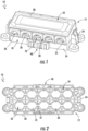
FIG. 1 is a perspective view illustrating a fuse holder according to exemplary embodiments of the disclosure; -
FIG. 2 is a bottom view of the fuse holder shown inFIG. 1 according to exemplary embodiments. -
FIG. 3 is an exploded view of the fuse holder shown inFIG. 1 according to exemplary embodiments of the disclosure; -
FIG. 4 is a side view illustrating a fuse holder according to exemplary embodiments of the disclosure; -
FIG. 5 is an end view of the fuse holder shown inFIG. 4 according to exemplary embodiments. -
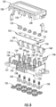
FIG. 6 is an exploded view of the fuse holder shown inFIG. 4 according to exemplary embodiments of the disclosure; -
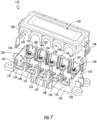
FIG. 7 is a partially exploded view of a fuse holder shown inFIG. 4 according to exemplary embodiments of the disclosure; -
FIG. 8 is a perspective view of a circuit protection assembly according to exemplary embodiments of the disclosure; -
FIG. 9 is a perspective view of a circuit protection assembly according to exemplary embodiments of the disclosure; and -
FIG. 10 is a perspective view of a circuit protection assembly according to exemplary embodiments of the disclosure. - Furthermore, certain elements in some of the figures may be omitted, or illustrated not-to-scale, for illustrative clarity. Cross-sectional views may be in the form of "slices", or "near-sighted" cross-sectional views, omitting certain background lines otherwise visible in a "true" cross-sectional view, for illustrative clarity. Furthermore, for clarity, some reference numbers may be omitted in certain drawings.
- A fuse holder, a circuit protection assembly, and a modular fuse holder assembly in accordance with the present disclosure will now be described more fully hereinafter with reference to the accompanying drawings, in which embodiments of the system and method are shown. The fuse holder, a circuit protection assembly, and modular fuse holder assembly, however, may be embodied in many different forms and should not be construed as being limited to the embodiments set forth herein. Rather, these embodiments are provided so that this disclosure will be thorough and complete, and will fully convey the scope of the system and method to those skilled in the art.
- For the sake of convenience and clarity, terms such as "top," "bottom," "upper," "lower," "vertical," "horizontal," "lateral," and "longitudinal" will be used herein to describe the relative placement and orientation of these components and their constituent parts, each with respect to the geometry and orientation of a modular fuse holder as they appear in the figures. Said terminology will include the words specifically mentioned, derivatives thereof, and words of similar import.
- As used herein, an element or operation recited in the singular and proceeded with the word "a" or "an" should be understood as not excluding plural elements or operations, unless such exclusion is explicitly recited. Furthermore, references to "one embodiment" of the present disclosure are not intended to be interpreted as excluding the existence of additional embodiments that also incorporate the recited features.
- Approaches herein provide for customized power distribution using a fuse holder for single bolt fuses. According to the present invention, fuse holder includes a base having a lower wall and a set of sidewalls, the lower wall including a plurality of bolt openings provided therethrough. The fuse holder further includes a cover securable with the base, the cover including an upper wall and a set of outer walls, the outer walls including a plurality of cable openings, wherein the base and the cover define an interior cavity for housing a bolt assembly. In some approaches, the fuse holder may include a busbar atop the lower wall of the base, the busbar including a set of openings aligned with one or more of the bolt openings of the lower wall. In some embodiments, a side cover may extend over some of the plurality of cable openings in the outer wall of the cover.
- One of ordinary skill in the art will appreciate that embodiments herein provide at least the following technical improvements and advantages over the existing art. Firstly, the modular fuse holder assembly allows multiple configurations to be easily attainable at the time of assembly. Even in the case of different overall capacity (e.g., number of fuses) holders, a common flexible architecture is shared. Secondly, press fit isolated bolt assemblies allow multiple configurations, including multiple bolt sizes and locations. Thirdly, using two rows of bolt assembly locations within the housing allows for entry of wires from either side of the housing, while still permitting sufficient strain relief and minimizing overall foot print. Fourthly, a combination side cover (i.e., dust cover) and fuse retainer keeps Z-case fuses in place for transportation without having to add a nut and lock washer. This saves labor on the installation side as the wires can be placed on the fuses and nuts tightened without having to remove all of the nuts first. Fifthly, flexible busing allows multiple configurations with common components. Sixthly, a dovetail feature along an exterior of the housing allows multiple fuse holders to be coupled together and bussed together.
- Referring to
FIGS. 1-3 , an exemplary embodiment of a modular fuse holder assembly (hereinafter, assembly 10) in accordance with the present disclosure is shown. Theassembly 10 includes ahousing assembly 12 having abase 18 coupled to acover 22, thecover 22 removably connected to thebase 18 and covering the components therein. Thecover 22 can be removed, for example, to replace one or more fuse components. As shown, thebase 18 includes alower wall 20 and a set ofsidewalls 24 extending from thelower wall 20. In some embodiments, the set ofsidewalls 24 extend perpendicularly from an upper surface of thelower wall 20. Thelower wall 20 may include a plurality ofbolt openings 25 provided therethrough. As will be described in greater detail below, the plurality ofbolt openings 25 permit one or more bolt assemblies to extend into acavity 26 defined by an open area within thebase 18 and thecover 22. - The
assembly 10 may further include one or more lower capping strips 33 coupled to a bottom side of thebase 18. As shown, the lower capping strips 33 may having alternating circular opening plugs 35 and linkingmembers 37, wherein the circular opening plugs 35 are configured to cover the plurality ofbolt openings 25 in thelower wall 20. In some embodiments, the lower capping strips 33 may be snap-fit into position by one or moreundercut features 39 securable to corresponding mating lips (not shown) within eachbolt opening 25. - As further shown, the
cover 22 includes anupper wall 28 and set ofouter walls 30, the set ofouter walls 30 including a plurality ofcable openings 32 to permit one or more cables (i.e., wires) to enter thehousing assembly 12 for connection with the bolt assemblies. In some embodiments, thecable openings 32 may have an arched or semicircular shape. Other shapes and dimensions for thecable openings 32 are possible within the scope of the present disclosure. - In some embodiments, the
cover 22 may be snap-fit to thebase 18 and/or include one or more brackets or latches 34 to releasably secure thecover 22 to thebase 18. In an alternative embodiment, thecover 22 is threaded onto thebase 18 and can include a spring seal that provides a tensile force against thecover 22, which tends to hold thecover 22 in a tight, threaded relationship with the base 18 even when the vehicle is moving and creating vibrations that could otherwise loosen thecover 22. The spring mechanism can also provide a seal between thecover 22 and thebase 18. Although not specifically illustrated, thecover 22 may also include means to further facilitate grasping and removal, such as tabs, projections, recesses, etc. - The base 18 may include a
sidewall interlocking feature 40 for mounting multiple housing assemblies together. In some embodiments, thesidewall interlocking feature 40 may include one or more dovetail-type members. Although not limited to any particular material, thehousing assembly 12 may be made of an insulating material, such as plastic, which is molded to form a demonstrated shape. In some embodiments, thebase 18 and thecover 22 can be made of the same or different materials, such as an insulating plastic, e.g., nylon, glass-filled nylon, polyester and polycarbonate. - In some embodiments, the
latches 34 may be coupled to a pin 42 (FIG. 3 ) of thebase 18, to permit thelatches 34 to pivot about an axis defined by the pin 42. When thecover 22 is not in use, thelatches 34 may rotate and extend away from thecover 22. Then, as thecover 22 is positioned onto thebase 18, thelatches 34 may be rotated towards thecover 22, and clamped about asecurement ridge 41 of thecover 22. - As best shown in
FIG. 3 , thehousing assembly 12 may include a set of interlocking features for coupling thecover 22 to thebase 18. For example, thebase 18 may include a plurality of pillar supports 44 extending upwardly from alower portion 45 of the set ofsidewalls 24. Each of the pillar supports 44 may include a pair ofouter flanges 48 defining amiddle slot 47 therebetween. Themiddle slot 47 is configured to receive one or more openingwalls 49 of thecover 22. During securement of thehousing assembly 12, the openingwalls 49 may be inserted into themiddle slot 47 until an interior surface of an upper wall 69 engages the pair ofouter flanges 48. - Referring now to
FIGS. 4-7 , an exemplary embodiment of another modular fuse holder assembly (hereinafter, assembly 110) in accordance with the present disclosure is shown. As shown, theassembly 110 includes many of the features previously described in relation to theassembly 10 ofFIGs. 1-3 and, as such, may not be described in full detail for the sake of brevity. Theassembly 110 includes ahousing assembly 112 having a base 118 coupled to acover 122, thecover 122 removably connected to thebase 118 and covering the components therein. As shown, thebase 118 includes alower wall 120 and a set ofsidewalls 124 extending from thelower wall 120. In some embodiments, the set ofsidewalls 124 extend perpendicularly from an upper surface of thelower wall 120. Thelower wall 120 includes a plurality of bolt openings 125 (FIG. 6 ) provided therethrough. The plurality ofbolt openings 125 permit one or more studs orbolt assemblies 150 to extend into acavity 126 defined by an open area within thebase 118 and thecover 122. In some embodiments, thecover 122 may be attached to thebase 118 by atether 146, which may be a looped silicon rubber connector coupled to each of thebase 118 and thecover 122. - As shown, the
assembly 110 includes one or more bolt assemblies 150 (e.g., Ni/Sn plated steel) extending through the plurality ofbolt openings 125, as well as through a plurality ofbus openings 151 of abusbar 152. For example, the bottom side of the base 118 may include recesses sized slightly larger than the heads of eachbolt assembly 150 within which these heads are disposed such that the respective bolts are secured in position through thelower wall 120. Thebolt assemblies 150 may be force fit into respective recesses of thebolt openings 125, wherein thebolt openings 125 have the same shape as respective heads of eachbolt assembly 150 with body portions of each of thebolt assemblies 150 extending throughlower wall 120. In this manner, the bolt assemblies do not need to be integrally molded with thebase 118, thereby reducing manufacturing and labor costs. - The
busbar 152 may be disposed atop thelower wall 120 of thebase 118, wherein the plurality ofbus openings 151 are aligned with one or more of the plurality ofbolt openings 125 of thelower wall 120. In some embodiments, thebolt assemblies 150 may be secured to thebusbar 152 by corresponding nuts 153. Furthermore, thebusbar 152 may be secured to the top surface of thelower wall 120 of the base by one or more fasteners 154 (e.g., press-fit tabs) extending from thelower wall 120 of the base. During use, thebolt assemblies 150 supply power to thebusbar 152, thebolt assemblies 150 being configured to receive fuses (not shown). Once thebolt assemblies 150 are inserted into thehousing assembly 112, one or more capping strips 135 may be inserted into the plurality ofbolt openings 125 in thelower wall 120. It will be appreciated that bolts of various size and position may be employed. - The
assembly 110 further includes aside cover 155 coupleable with thebase 118, theside cover 155 configured to extend between at least one of the plurality ofcable openings 132 in theouter wall 130 of thecover 122, as well as over at least one of a plurality ofopenings 158 defined by each of a plurality of pillar supports 144 of thebase 118. As shown, theside cover 155 may include a plurality ofchannels 156 configured to receive and surround corresponding pillar supports 144. More specifically, each of the side covers 155 may include one or more slottedside walls 180 slidably engaged with correspondingouter flanges 148 of the pillar supports 144. In some embodiments, extending between each of the plurality ofchannels 156 is acentral block 157 arranged withinopenings 158 between each of the plurality of pillar supports 144. Theside cover 155 may include a set oftabs 160 for engaging a channel 161 of one or more of the plurality of pillar supports 144 to secure theside cover 155 to thebase 118. - As will be appreciated, the
side cover 155 may act as a debris cover for minimizing intrusion of dust or other contaminants into thecavity 126. In some embodiments, theside cover 155 may be a series of unconnected components arranged side by side, enabling flexible, interchangeable placement over theopenings 158 between each of the pillar supports 144. In other embodiments, theside cover 155 may be a continuous piece of material (e.g., silicon rubber) covering all of theplurality openings 158. - After the
side cover 155 is coupled to thebase 118, thecover 122 may be placed atop thebase 118. That is, themiddle slot 147 of eachpillar support 144 is configured to receive one or more openingwalls 149 of thecover 122. The openingwalls 149 may be inserted into themiddle slot 147 until an interior surface of an upper wall 169 engages the pair ofouter flanges 148. - As better shown in
FIG. 6 , theside cover 155 may include a plurality of fuse supports 162 extending between thecentral block 157 and afuse alignment wall 164. In some embodiments, each of the plurality of fuse supports 162 is a corner shelf or stop configured to engage a fuse (not shown) to keep the fuse in place without a nut. The plurality of fuse supports 162 of theside cover 155 may advantageously save assembly time because there's no need to unscrew the nut before attaching the wire. Furthermore, in some embodiments, with the fuses and theside cover 155 assembled, thebusbar 152 may also be kept in place without any screw, snap-in locking or similar. - Turning now to
FIGs. 8-10 , a circuit protection assembly (hereinafter "assembly") 210 according to embodiments of the present disclosure will be described in greater detail. As shown, theassembly 210 includes many the features previously described in relation to theassembly 10 and theassembly 110 and, as such, will not be described in full detail for the sake of brevity. Theassembly 210 includes ahousing assembly 212 having a base 218 coupled to a cover 222 (FIG. 10 ), thecover 222 removably connected to thebase 218 and covering the components therein. As shown, thebase 218 includes a set ofsidewalls 224 extending from thelower wall 220. Thelower wall 220 includes a plurality of bolt openings 225 (FIG. 6 ) provided therethrough. The plurality ofbolt openings 225 permit one ormore bolt assemblies 250 to extend into acavity 226 defined by an open area within thebase 218 and thecover 222. - As shown, the
assembly 210 includes one ormore bolt assemblies 250 extending through the plurality ofbolt openings 225, as well as through a plurality of busbar openings 251 of abusbar 252. Thebusbar 252 may be disposed atop an upper/inner surface of thelower wall 220 of thebase 218, wherein the plurality of busbar openings 251 may be aligned with one or more of the plurality ofbolt openings 225 of thelower wall 220. In some embodiments, thebolt assemblies 250 may be secured in place by corresponding nuts 253. - The
assembly 210 may include one or more side covers 255 coupleable with thebase 218, theside cover 255 is configured to extend across one or more openings 258 between each of the plurality of pillar supports 244. As shown, theassembly 210 may further include one or more cable covers 265 extending over at least one of a plurality of openings between each of the plurality of pillar supports 244. The cable covers 265 include an opening for receiving a wire orcable 266. The cable covers 265 may further include a pair of slottedend walls 272 slidably engaged with theouter flanges 248 of the pillar supports 244. As will be appreciated, the cable covers 265 may act as debris covers for minimizing intrusion of dust or other contaminants into thebase 218. - The
side cover 255 may include a plurality of fuse supports 262, such as a corner shelf, tab, or stop configured to engage thefuse 268 to keep the fuse in place without a nut. The plurality of fuse supports 262 of theside cover 255 may advantageously save assembly time because there's no need to unscrew thebolt assembly 250 before attaching the wire orcable 266. - In some embodiments, the
cable 266 and thebolt assembly 250 are coupled to afuse 268, wherein thebolt assembly 250 is disposed through a receiving bore in thefuse 268. Thefuse 268 may be a ceramic "block" fuse having a generally central aperture that receives thebolt assembly 250. In some embodiments, an insulator isolates thebolt assembly 250 from thefuse 268. Aring terminal 270, connected to thecable 266, is mounted over thebolt assembly 250, while thenut 253 threadedly engages thebolt assembly 250 to retain both thefuse 268 and thering terminal 270 in position. As shown, thecables 266 may extend outside of the base 218 on either side, through the cable covers 265, thus providing increased design flexibility. In some cases, depending on the size of thering terminal 270 andcable 266, nocable cover 265 is present between a pair of pillar supports 244. This is demonstrated with cable 266-1, which may be a relatively larger wire coupled to, e.g., an M10 bolt. - After the
side cover 255 and the cable cover(s) 265 are coupled to thebase 218, and thering terminal 270 is secured in place with thenut 253, thecover 222 may be placed atop thebase 218. That is, themiddle slot 247 of eachpillar support 244 is configured to receive one or more openingwalls 249 of thecover 222. When cable covers 265 are present, the openingwalls 249 may engage the pair of slottedend walls 272 to further secure the cable covers 265 to thebase 218. Furthermore, withfuses 268 and thecovers busbar 252 may also be kept in place without any screw, snap-in locking or similar, thus simplifying assembly and reducing cost.
Claims (9)
- A fuse holder (110), comprising:a base (118) including a lower wall (120) and a set of sidewalls (124), the lower wall (120) including a plurality of bolt openings (125) provided therethrough wherein the set of sidewalls (124) of the base (118) comprises a plurality of pillar supports (144) defining a plurality of openings (158) into an interior cavity (126),a cover (122) securable with the base (118), the cover (122) including an upper wall (169) and a set of outer walls (130), the set of outer walls (130) including a plurality of cable openings (132) and wherein the base (118) and the cover define the interior cavity (126) for housing a bolt assembly,characterized in thateach of the plurality of pillar supports (144) comprises:a pair of outer flanges (148); anda middle slot (147) between the pair of outer flanges (148); andthe set of outer walls (130) includes a plurality of opening walls (149),wherein the middle slot (147) of each pillar support of the plurality of pillar supports (144) receives a corresponding opening wall of the plurality of opening walls (149).
- The fuse holder (110) of claim 1, further comprising:
a lower capping strip (135) covering the plurality of bolt openings (125) in the lower wall (120). - The fuse holder of claim 2, wherein the lower capping strip (135) comprises a plurality of opening plugs (35) insertable into the plurality of bolt openings (125).
- The fuse holder (110) of any of the claims 1-3, further comprising a busbar (152) disposed atop the lower wall (120) of the base (118), the busbar (152) including a set of openings (151) aligned with one or more of the plurality of bolt openings (125) of the lower wall (120).
- The fuse holder (110) of claim 4, further comprising a plurality of fasteners (154) extending from the lower wall (120) of the base (118), the plurality of fasteners (154) mechanically coupling the busbar (152) to the lower wall (120) of the base (118).
- The fuse holder (110) of any of the preceding claims, further comprising a side cover (155) coupled to the base (118), the side cover (155) extending across at least one of the plurality of cable openings (132) in the set of outer walls (130) of the cover (122).
- The fuse holder (110) of claim 6, wherein the side cover (155) and the base (118) have corresponding interlocking features permitting the side cover (155) to slide into position.
- The fuse holder (110) of claim 1, further comprising one or more cable covers (265) extending over at least one of the plurality of openings (158) in the set of sidewalls (124) of the base (118).
- A circuit protection assembly comprising a fuse holder according to any of the preceding claims.
Applications Claiming Priority (2)
| Application Number | Priority Date | Filing Date | Title |
|---|---|---|---|
| US15/877,463 US10361055B1 (en) | 2018-01-23 | 2018-01-23 | Modular single bolt fuse holder |
| PCT/US2019/013984 WO2019147468A1 (en) | 2018-01-23 | 2019-01-17 | Modular single bolt fuse holder |
Publications (3)
| Publication Number | Publication Date |
|---|---|
| EP3743936A1 EP3743936A1 (en) | 2020-12-02 |
| EP3743936A4 EP3743936A4 (en) | 2021-08-11 |
| EP3743936B1 true EP3743936B1 (en) | 2024-10-16 |
Family
ID=67300082
Family Applications (1)
| Application Number | Title | Priority Date | Filing Date |
|---|---|---|---|
| EP19743689.2A Active EP3743936B1 (en) | 2018-01-23 | 2019-01-17 | Modular single bolt fuse holder |
Country Status (5)
| Country | Link |
|---|---|
| US (1) | US10361055B1 (en) |
| EP (1) | EP3743936B1 (en) |
| KR (1) | KR102738571B1 (en) |
| CN (1) | CN111656480B (en) |
| WO (1) | WO2019147468A1 (en) |
Families Citing this family (4)
| Publication number | Priority date | Publication date | Assignee | Title |
|---|---|---|---|---|
| US12033824B2 (en) | 2021-08-09 | 2024-07-09 | Xenon Inc. | Fuse holder |
| CN116013747A (en) * | 2021-10-22 | 2023-04-25 | 苏州力特奥维斯保险丝有限公司 | Sealed inline fuse module |
| CN116153738A (en) | 2021-11-19 | 2023-05-23 | 苏州力特奥维斯保险丝有限公司 | Fuse modules with clip-on fuse mounts |
| US11817284B1 (en) * | 2022-09-12 | 2023-11-14 | Littelfuse, Inc. | Unsealed single fuse holder |
Family Cites Families (20)
| Publication number | Priority date | Publication date | Assignee | Title |
|---|---|---|---|---|
| GB597968A (en) * | 1945-09-05 | 1948-02-06 | Electrical Components Ltd | An improved electrical fuse distribution board |
| US5645448A (en) * | 1995-10-16 | 1997-07-08 | Yazaki Corporation | Battery connecting module with fuse mounting |
| JPH10255642A (en) * | 1997-03-11 | 1998-09-25 | Yazaki Corp | Fuse holder |
| US5973418A (en) * | 1998-05-05 | 1999-10-26 | Cooper Technologies Company | Pull-out high current switch |
| US6431880B1 (en) * | 1998-06-22 | 2002-08-13 | Cooper Technologies | Modular terminal fuse block |
| DE10323550A1 (en) * | 2003-05-24 | 2004-12-23 | Leoni Bordnetz-Systeme Gmbh & Co Kg | Fuse box for a vehicle |
| US7878822B2 (en) * | 2004-12-10 | 2011-02-01 | Cooper Technologies Company | Sealed compact power distribution module |
| DE202008000405U1 (en) * | 2008-01-10 | 2008-04-30 | Stadtfeld Elektrotechnische Fabrik Gmbh & Co. Kg | Cable junction box, in particular for installation in light poles or the like. |
| US7978482B2 (en) * | 2008-08-14 | 2011-07-12 | Rockwell Automation Technologies, Inc. | Modular high-power fuse carrier |
| DE102010028679B4 (en) * | 2010-05-06 | 2020-08-06 | Wöhner GmbH & Co. KG Elektrotechnische Systeme | Fuse holder, in particular for junction boxes of photovoltaic systems |
| US8669840B2 (en) * | 2010-05-18 | 2014-03-11 | Littelfuse, Inc. | Fuse assembly |
| DE102010055554A1 (en) * | 2010-12-23 | 2012-06-28 | Gm Global Technology Operations, Inc. | Caged nut with holding device and method for producing the same |
| JP5695975B2 (en) * | 2011-05-26 | 2015-04-08 | 矢崎総業株式会社 | Fusible link mounting structure and electrical junction box |
| JP5864151B2 (en) * | 2011-07-28 | 2016-02-17 | 矢崎総業株式会社 | Bolt support structure |
| US9306379B2 (en) * | 2013-01-16 | 2016-04-05 | William Greenberg | Fuse and power distribution block |
| US10056596B2 (en) * | 2013-06-06 | 2018-08-21 | Te Connectivity Corporation | Battery connector assembly |
| CN104319207B (en) * | 2014-10-24 | 2016-10-05 | 长城汽车股份有限公司 | A kind of Joker type safety box and automobile |
| US10040412B2 (en) * | 2016-05-10 | 2018-08-07 | Deere & Company | Utility vehicle power distribution module |
| US10395878B2 (en) * | 2016-05-24 | 2019-08-27 | Eaton Intelligent Power Limited | Modular fuse holder and arrangement and connection thereof |
| US9842718B1 (en) * | 2016-06-10 | 2017-12-12 | Sumitomo Wiring Systems, Ltd. | Fuse array for vehicle electrical system having multiple discrete circuits |
-
2018
- 2018-01-23 US US15/877,463 patent/US10361055B1/en active Active
-
2019
- 2019-01-17 CN CN201980009753.XA patent/CN111656480B/en active Active
- 2019-01-17 WO PCT/US2019/013984 patent/WO2019147468A1/en not_active Ceased
- 2019-01-17 KR KR1020207021703A patent/KR102738571B1/en active Active
- 2019-01-17 EP EP19743689.2A patent/EP3743936B1/en active Active
Also Published As
| Publication number | Publication date |
|---|---|
| KR20200108440A (en) | 2020-09-18 |
| US20190228940A1 (en) | 2019-07-25 |
| KR102738571B1 (en) | 2024-12-05 |
| CN111656480A (en) | 2020-09-11 |
| EP3743936A4 (en) | 2021-08-11 |
| EP3743936A1 (en) | 2020-12-02 |
| US10361055B1 (en) | 2019-07-23 |
| CN111656480B (en) | 2024-01-05 |
| WO2019147468A1 (en) | 2019-08-01 |
Similar Documents
| Publication | Publication Date | Title |
|---|---|---|
| US10361055B1 (en) | Modular single bolt fuse holder | |
| US7878822B2 (en) | Sealed compact power distribution module | |
| US10497920B2 (en) | Battery system | |
| CN1134038C (en) | Fuse box for motor vehicles | |
| EP1197397B1 (en) | Electrical connection box for a vehicle | |
| EP3758099B1 (en) | Bolted bus bar with finger-proofing | |
| US20130095696A1 (en) | Fuse unit | |
| US9686877B2 (en) | Locking structure between member to be supported and supporting body | |
| CA2591661C (en) | In-line fuse holder for female fuse | |
| JP5702314B2 (en) | Switchable fuse distribution block | |
| US9911565B2 (en) | Sealed modular power distribution apparatus | |
| US7192319B1 (en) | Insulated cable termination assembly and method of fabrication | |
| DE19924911A1 (en) | Current distributor block e.g. fuse block for automobile electrics | |
| US11532901B2 (en) | Electrical device | |
| US5716243A (en) | Automotive battery connector assembly | |
| EP4064319B1 (en) | Attaching an isolated single stud fuse to an electrical device | |
| EP3685418B1 (en) | Integrated fuse module | |
| US10790601B1 (en) | Electrical conductor pass through plate constructions | |
| EP2347472B1 (en) | Method and device for facilitating connection to a battery | |
| US20210249738A1 (en) | Interlock structure of battery pack | |
| EP4184547B1 (en) | Fuse module with clamped fuse installation | |
| RU2091930C1 (en) | Connecting module | |
| US20260112552A1 (en) | Loto for msd switch, power battery and work machinery | |
| EP1548786B1 (en) | Fuse connection structure of bus bar and electric connection box provided with same | |
| KR200142576Y1 (en) | Battery having line concent |
Legal Events
| Date | Code | Title | Description |
|---|---|---|---|
| STAA | Information on the status of an ep patent application or granted ep patent |
Free format text: STATUS: THE INTERNATIONAL PUBLICATION HAS BEEN MADE |
|
| PUAI | Public reference made under article 153(3) epc to a published international application that has entered the european phase |
Free format text: ORIGINAL CODE: 0009012 |
|
| STAA | Information on the status of an ep patent application or granted ep patent |
Free format text: STATUS: REQUEST FOR EXAMINATION WAS MADE |
|
| 17P | Request for examination filed |
Effective date: 20200817 |
|
| AK | Designated contracting states |
Kind code of ref document: A1 Designated state(s): AL AT BE BG CH CY CZ DE DK EE ES FI FR GB GR HR HU IE IS IT LI LT LU LV MC MK MT NL NO PL PT RO RS SE SI SK SM TR |
|
| AX | Request for extension of the european patent |
Extension state: BA ME |
|
| DAV | Request for validation of the european patent (deleted) | ||
| DAX | Request for extension of the european patent (deleted) | ||
| A4 | Supplementary search report drawn up and despatched |
Effective date: 20210709 |
|
| RIC1 | Information provided on ipc code assigned before grant |
Ipc: H01H 85/20 20060101AFI20210705BHEP |
|
| STAA | Information on the status of an ep patent application or granted ep patent |
Free format text: STATUS: EXAMINATION IS IN PROGRESS |
|
| 17Q | First examination report despatched |
Effective date: 20220809 |
|
| GRAP | Despatch of communication of intention to grant a patent |
Free format text: ORIGINAL CODE: EPIDOSNIGR1 |
|
| STAA | Information on the status of an ep patent application or granted ep patent |
Free format text: STATUS: GRANT OF PATENT IS INTENDED |
|
| RIC1 | Information provided on ipc code assigned before grant |
Ipc: H01H 85/02 20060101ALN20240509BHEP Ipc: H01H 85/20 20060101AFI20240509BHEP |
|
| RIC1 | Information provided on ipc code assigned before grant |
Ipc: H01H 85/02 20060101ALN20240517BHEP Ipc: H01H 85/20 20060101AFI20240517BHEP |
|
| INTG | Intention to grant announced |
Effective date: 20240604 |
|
| GRAS | Grant fee paid |
Free format text: ORIGINAL CODE: EPIDOSNIGR3 |
|
| GRAA | (expected) grant |
Free format text: ORIGINAL CODE: 0009210 |
|
| STAA | Information on the status of an ep patent application or granted ep patent |
Free format text: STATUS: THE PATENT HAS BEEN GRANTED |
|
| AK | Designated contracting states |
Kind code of ref document: B1 Designated state(s): AL AT BE BG CH CY CZ DE DK EE ES FI FR GB GR HR HU IE IS IT LI LT LU LV MC MK MT NL NO PL PT RO RS SE SI SK SM TR |
|
| REG | Reference to a national code |
Ref country code: GB Ref legal event code: FG4D |
|
| P01 | Opt-out of the competence of the unified patent court (upc) registered |
Free format text: CASE NUMBER: APP_52287/2024 Effective date: 20240918 |
|
| REG | Reference to a national code |
Ref country code: CH Ref legal event code: EP Ref country code: DE Ref legal event code: R096 Ref document number: 602019060494 Country of ref document: DE |
|
| REG | Reference to a national code |
Ref country code: IE Ref legal event code: FG4D |
|
| REG | Reference to a national code |
Ref country code: LT Ref legal event code: MG9D |
|
| REG | Reference to a national code |
Ref country code: NL Ref legal event code: MP Effective date: 20241016 |
|
| REG | Reference to a national code |
Ref country code: AT Ref legal event code: MK05 Ref document number: 1733655 Country of ref document: AT Kind code of ref document: T Effective date: 20241016 |
|
| PG25 | Lapsed in a contracting state [announced via postgrant information from national office to epo] |
Ref country code: NL Free format text: LAPSE BECAUSE OF FAILURE TO SUBMIT A TRANSLATION OF THE DESCRIPTION OR TO PAY THE FEE WITHIN THE PRESCRIBED TIME-LIMIT Effective date: 20241016 |
|
| PG25 | Lapsed in a contracting state [announced via postgrant information from national office to epo] |
Ref country code: NL Free format text: LAPSE BECAUSE OF FAILURE TO SUBMIT A TRANSLATION OF THE DESCRIPTION OR TO PAY THE FEE WITHIN THE PRESCRIBED TIME-LIMIT Effective date: 20241016 |
|
| PG25 | Lapsed in a contracting state [announced via postgrant information from national office to epo] |
Ref country code: PT Free format text: LAPSE BECAUSE OF FAILURE TO SUBMIT A TRANSLATION OF THE DESCRIPTION OR TO PAY THE FEE WITHIN THE PRESCRIBED TIME-LIMIT Effective date: 20250217 Ref country code: IS Free format text: LAPSE BECAUSE OF FAILURE TO SUBMIT A TRANSLATION OF THE DESCRIPTION OR TO PAY THE FEE WITHIN THE PRESCRIBED TIME-LIMIT Effective date: 20250216 Ref country code: HR Free format text: LAPSE BECAUSE OF FAILURE TO SUBMIT A TRANSLATION OF THE DESCRIPTION OR TO PAY THE FEE WITHIN THE PRESCRIBED TIME-LIMIT Effective date: 20241016 |
|
| PG25 | Lapsed in a contracting state [announced via postgrant information from national office to epo] |
Ref country code: FI Free format text: LAPSE BECAUSE OF FAILURE TO SUBMIT A TRANSLATION OF THE DESCRIPTION OR TO PAY THE FEE WITHIN THE PRESCRIBED TIME-LIMIT Effective date: 20241016 |
|
| PG25 | Lapsed in a contracting state [announced via postgrant information from national office to epo] |
Ref country code: BG Free format text: LAPSE BECAUSE OF FAILURE TO SUBMIT A TRANSLATION OF THE DESCRIPTION OR TO PAY THE FEE WITHIN THE PRESCRIBED TIME-LIMIT Effective date: 20241016 |
|
| PG25 | Lapsed in a contracting state [announced via postgrant information from national office to epo] |
Ref country code: ES Free format text: LAPSE BECAUSE OF FAILURE TO SUBMIT A TRANSLATION OF THE DESCRIPTION OR TO PAY THE FEE WITHIN THE PRESCRIBED TIME-LIMIT Effective date: 20241016 |
|
| PG25 | Lapsed in a contracting state [announced via postgrant information from national office to epo] |
Ref country code: NO Free format text: LAPSE BECAUSE OF FAILURE TO SUBMIT A TRANSLATION OF THE DESCRIPTION OR TO PAY THE FEE WITHIN THE PRESCRIBED TIME-LIMIT Effective date: 20250116 |
|
| PG25 | Lapsed in a contracting state [announced via postgrant information from national office to epo] |
Ref country code: LV Free format text: LAPSE BECAUSE OF FAILURE TO SUBMIT A TRANSLATION OF THE DESCRIPTION OR TO PAY THE FEE WITHIN THE PRESCRIBED TIME-LIMIT Effective date: 20241016 Ref country code: GR Free format text: LAPSE BECAUSE OF FAILURE TO SUBMIT A TRANSLATION OF THE DESCRIPTION OR TO PAY THE FEE WITHIN THE PRESCRIBED TIME-LIMIT Effective date: 20250117 Ref country code: AT Free format text: LAPSE BECAUSE OF FAILURE TO SUBMIT A TRANSLATION OF THE DESCRIPTION OR TO PAY THE FEE WITHIN THE PRESCRIBED TIME-LIMIT Effective date: 20241016 |
|
| PG25 | Lapsed in a contracting state [announced via postgrant information from national office to epo] |
Ref country code: PL Free format text: LAPSE BECAUSE OF FAILURE TO SUBMIT A TRANSLATION OF THE DESCRIPTION OR TO PAY THE FEE WITHIN THE PRESCRIBED TIME-LIMIT Effective date: 20241016 |
|
| PG25 | Lapsed in a contracting state [announced via postgrant information from national office to epo] |
Ref country code: RS Free format text: LAPSE BECAUSE OF FAILURE TO SUBMIT A TRANSLATION OF THE DESCRIPTION OR TO PAY THE FEE WITHIN THE PRESCRIBED TIME-LIMIT Effective date: 20250116 |
|
| PG25 | Lapsed in a contracting state [announced via postgrant information from national office to epo] |
Ref country code: SM Free format text: LAPSE BECAUSE OF FAILURE TO SUBMIT A TRANSLATION OF THE DESCRIPTION OR TO PAY THE FEE WITHIN THE PRESCRIBED TIME-LIMIT Effective date: 20241016 |
|
| PG25 | Lapsed in a contracting state [announced via postgrant information from national office to epo] |
Ref country code: DK Free format text: LAPSE BECAUSE OF FAILURE TO SUBMIT A TRANSLATION OF THE DESCRIPTION OR TO PAY THE FEE WITHIN THE PRESCRIBED TIME-LIMIT Effective date: 20241016 |
|
| REG | Reference to a national code |
Ref country code: DE Ref legal event code: R097 Ref document number: 602019060494 Country of ref document: DE |
|
| PG25 | Lapsed in a contracting state [announced via postgrant information from national office to epo] |
Ref country code: EE Free format text: LAPSE BECAUSE OF FAILURE TO SUBMIT A TRANSLATION OF THE DESCRIPTION OR TO PAY THE FEE WITHIN THE PRESCRIBED TIME-LIMIT Effective date: 20241016 |
|
| PG25 | Lapsed in a contracting state [announced via postgrant information from national office to epo] |
Ref country code: RO Free format text: LAPSE BECAUSE OF FAILURE TO SUBMIT A TRANSLATION OF THE DESCRIPTION OR TO PAY THE FEE WITHIN THE PRESCRIBED TIME-LIMIT Effective date: 20241016 |
|
| PG25 | Lapsed in a contracting state [announced via postgrant information from national office to epo] |
Ref country code: SK Free format text: LAPSE BECAUSE OF FAILURE TO SUBMIT A TRANSLATION OF THE DESCRIPTION OR TO PAY THE FEE WITHIN THE PRESCRIBED TIME-LIMIT Effective date: 20241016 |
|
| PG25 | Lapsed in a contracting state [announced via postgrant information from national office to epo] |
Ref country code: CZ Free format text: LAPSE BECAUSE OF FAILURE TO SUBMIT A TRANSLATION OF THE DESCRIPTION OR TO PAY THE FEE WITHIN THE PRESCRIBED TIME-LIMIT Effective date: 20241016 |
|
| PLBE | No opposition filed within time limit |
Free format text: ORIGINAL CODE: 0009261 |
|
| STAA | Information on the status of an ep patent application or granted ep patent |
Free format text: STATUS: NO OPPOSITION FILED WITHIN TIME LIMIT |
|
| REG | Reference to a national code |
Ref country code: CH Ref legal event code: PL |
|
| PG25 | Lapsed in a contracting state [announced via postgrant information from national office to epo] |
Ref country code: SE Free format text: LAPSE BECAUSE OF FAILURE TO SUBMIT A TRANSLATION OF THE DESCRIPTION OR TO PAY THE FEE WITHIN THE PRESCRIBED TIME-LIMIT Effective date: 20241016 |
|
| PG25 | Lapsed in a contracting state [announced via postgrant information from national office to epo] |
Ref country code: MC Free format text: LAPSE BECAUSE OF FAILURE TO SUBMIT A TRANSLATION OF THE DESCRIPTION OR TO PAY THE FEE WITHIN THE PRESCRIBED TIME-LIMIT Effective date: 20241016 Ref country code: LU Free format text: LAPSE BECAUSE OF NON-PAYMENT OF DUE FEES Effective date: 20250117 |
|
| 26N | No opposition filed |
Effective date: 20250717 |
|
| PG25 | Lapsed in a contracting state [announced via postgrant information from national office to epo] |
Ref country code: BE Free format text: LAPSE BECAUSE OF NON-PAYMENT OF DUE FEES Effective date: 20250131 |
|
| PG25 | Lapsed in a contracting state [announced via postgrant information from national office to epo] |
Ref country code: FR Free format text: LAPSE BECAUSE OF NON-PAYMENT OF DUE FEES Effective date: 20250131 |
|
| PG25 | Lapsed in a contracting state [announced via postgrant information from national office to epo] |
Ref country code: CH Free format text: LAPSE BECAUSE OF NON-PAYMENT OF DUE FEES Effective date: 20250131 |
|
| REG | Reference to a national code |
Ref country code: BE Ref legal event code: MM Effective date: 20250131 |
|
| PGFP | Annual fee paid to national office [announced via postgrant information from national office to epo] |
Ref country code: GB Payment date: 20251204 Year of fee payment: 8 |
|
| PG25 | Lapsed in a contracting state [announced via postgrant information from national office to epo] |
Ref country code: IE Free format text: LAPSE BECAUSE OF NON-PAYMENT OF DUE FEES Effective date: 20250117 |
|
| PGFP | Annual fee paid to national office [announced via postgrant information from national office to epo] |
Ref country code: DE Payment date: 20251203 Year of fee payment: 8 |
|
| PGFP | Annual fee paid to national office [announced via postgrant information from national office to epo] |
Ref country code: IT Payment date: 20251219 Year of fee payment: 8 |