EP3743619B1 - Power take-off for a wave energy converter - Google Patents
Power take-off for a wave energy converter Download PDFInfo
- Publication number
- EP3743619B1 EP3743619B1 EP19743158.8A EP19743158A EP3743619B1 EP 3743619 B1 EP3743619 B1 EP 3743619B1 EP 19743158 A EP19743158 A EP 19743158A EP 3743619 B1 EP3743619 B1 EP 3743619B1
- Authority
- EP
- European Patent Office
- Prior art keywords
- stators
- wave energy
- linear generator
- floating body
- pto
- Prior art date
- Legal status (The legal status is an assumption and is not a legal conclusion. Google has not performed a legal analysis and makes no representation as to the accuracy of the status listed.)
- Active
Links
Images



Classifications
-
- F—MECHANICAL ENGINEERING; LIGHTING; HEATING; WEAPONS; BLASTING
- F03—MACHINES OR ENGINES FOR LIQUIDS; WIND, SPRING, OR WEIGHT MOTORS; PRODUCING MECHANICAL POWER OR A REACTIVE PROPULSIVE THRUST, NOT OTHERWISE PROVIDED FOR
- F03B—MACHINES OR ENGINES FOR LIQUIDS
- F03B13/00—Adaptations of machines or engines for special use; Combinations of machines or engines with driving or driven apparatus; Power stations or aggregates
- F03B13/12—Adaptations of machines or engines for special use; Combinations of machines or engines with driving or driven apparatus; Power stations or aggregates characterised by using wave or tide energy
- F03B13/14—Adaptations of machines or engines for special use; Combinations of machines or engines with driving or driven apparatus; Power stations or aggregates characterised by using wave or tide energy using wave energy
- F03B13/16—Adaptations of machines or engines for special use; Combinations of machines or engines with driving or driven apparatus; Power stations or aggregates characterised by using wave or tide energy using wave energy using the relative movement between a wave-operated member, i.e. a "wom" and another member, i.e. a reaction member or "rem"
- F03B13/18—Adaptations of machines or engines for special use; Combinations of machines or engines with driving or driven apparatus; Power stations or aggregates characterised by using wave or tide energy using wave energy using the relative movement between a wave-operated member, i.e. a "wom" and another member, i.e. a reaction member or "rem" where the other member, i.e. rem is fixed, at least at one point, with respect to the sea bed or shore
- F03B13/1845—Adaptations of machines or engines for special use; Combinations of machines or engines with driving or driven apparatus; Power stations or aggregates characterised by using wave or tide energy using wave energy using the relative movement between a wave-operated member, i.e. a "wom" and another member, i.e. a reaction member or "rem" where the other member, i.e. rem is fixed, at least at one point, with respect to the sea bed or shore and the wom slides relative to the rem
- F03B13/1855—Adaptations of machines or engines for special use; Combinations of machines or engines with driving or driven apparatus; Power stations or aggregates characterised by using wave or tide energy using wave energy using the relative movement between a wave-operated member, i.e. a "wom" and another member, i.e. a reaction member or "rem" where the other member, i.e. rem is fixed, at least at one point, with respect to the sea bed or shore and the wom slides relative to the rem where the connection between wom and conversion system takes tension and compression
-
- F—MECHANICAL ENGINEERING; LIGHTING; HEATING; WEAPONS; BLASTING
- F03—MACHINES OR ENGINES FOR LIQUIDS; WIND, SPRING, OR WEIGHT MOTORS; PRODUCING MECHANICAL POWER OR A REACTIVE PROPULSIVE THRUST, NOT OTHERWISE PROVIDED FOR
- F03B—MACHINES OR ENGINES FOR LIQUIDS
- F03B13/00—Adaptations of machines or engines for special use; Combinations of machines or engines with driving or driven apparatus; Power stations or aggregates
- F03B13/12—Adaptations of machines or engines for special use; Combinations of machines or engines with driving or driven apparatus; Power stations or aggregates characterised by using wave or tide energy
- F03B13/14—Adaptations of machines or engines for special use; Combinations of machines or engines with driving or driven apparatus; Power stations or aggregates characterised by using wave or tide energy using wave energy
- F03B13/16—Adaptations of machines or engines for special use; Combinations of machines or engines with driving or driven apparatus; Power stations or aggregates characterised by using wave or tide energy using wave energy using the relative movement between a wave-operated member, i.e. a "wom" and another member, i.e. a reaction member or "rem"
- F03B13/20—Adaptations of machines or engines for special use; Combinations of machines or engines with driving or driven apparatus; Power stations or aggregates characterised by using wave or tide energy using wave energy using the relative movement between a wave-operated member, i.e. a "wom" and another member, i.e. a reaction member or "rem" wherein both members, i.e. wom and rem are movable relative to the sea bed or shore
-
- F—MECHANICAL ENGINEERING; LIGHTING; HEATING; WEAPONS; BLASTING
- F03—MACHINES OR ENGINES FOR LIQUIDS; WIND, SPRING, OR WEIGHT MOTORS; PRODUCING MECHANICAL POWER OR A REACTIVE PROPULSIVE THRUST, NOT OTHERWISE PROVIDED FOR
- F03B—MACHINES OR ENGINES FOR LIQUIDS
- F03B15/00—Controlling
-
- H—ELECTRICITY
- H02—GENERATION; CONVERSION OR DISTRIBUTION OF ELECTRIC POWER
- H02K—DYNAMO-ELECTRIC MACHINES
- H02K35/00—Generators with reciprocating, oscillating or vibrating coil system, magnet, armature or other part of the magnetic circuit
- H02K35/02—Generators with reciprocating, oscillating or vibrating coil system, magnet, armature or other part of the magnetic circuit with moving magnets and stationary coil systems
-
- H—ELECTRICITY
- H02—GENERATION; CONVERSION OR DISTRIBUTION OF ELECTRIC POWER
- H02K—DYNAMO-ELECTRIC MACHINES
- H02K7/00—Arrangements for handling mechanical energy structurally associated with dynamo-electric machines, e.g. structural association with mechanical driving motors or auxiliary dynamo-electric machines
- H02K7/18—Structural association of electric generators with mechanical driving motors, e.g. with turbines
- H02K7/1869—Linear generators; sectional generators
-
- H—ELECTRICITY
- H02—GENERATION; CONVERSION OR DISTRIBUTION OF ELECTRIC POWER
- H02K—DYNAMO-ELECTRIC MACHINES
- H02K7/00—Arrangements for handling mechanical energy structurally associated with dynamo-electric machines, e.g. structural association with mechanical driving motors or auxiliary dynamo-electric machines
- H02K7/18—Structural association of electric generators with mechanical driving motors, e.g. with turbines
- H02K7/1869—Linear generators; sectional generators
- H02K7/1876—Linear generators; sectional generators with reciprocating, linearly oscillating or vibrating parts
-
- F—MECHANICAL ENGINEERING; LIGHTING; HEATING; WEAPONS; BLASTING
- F05—INDEXING SCHEMES RELATING TO ENGINES OR PUMPS IN VARIOUS SUBCLASSES OF CLASSES F01-F04
- F05B—INDEXING SCHEME RELATING TO WIND, SPRING, WEIGHT, INERTIA OR LIKE MOTORS, TO MACHINES OR ENGINES FOR LIQUIDS COVERED BY SUBCLASSES F03B, F03D AND F03G
- F05B2220/00—Application
- F05B2220/70—Application in combination with
- F05B2220/706—Application in combination with an electrical generator
- F05B2220/7068—Application in combination with an electrical generator equipped with permanent magnets
-
- F—MECHANICAL ENGINEERING; LIGHTING; HEATING; WEAPONS; BLASTING
- F05—INDEXING SCHEMES RELATING TO ENGINES OR PUMPS IN VARIOUS SUBCLASSES OF CLASSES F01-F04
- F05B—INDEXING SCHEME RELATING TO WIND, SPRING, WEIGHT, INERTIA OR LIKE MOTORS, TO MACHINES OR ENGINES FOR LIQUIDS COVERED BY SUBCLASSES F03B, F03D AND F03G
- F05B2220/00—Application
- F05B2220/70—Application in combination with
- F05B2220/706—Application in combination with an electrical generator
- F05B2220/707—Application in combination with an electrical generator of the linear type
-
- F—MECHANICAL ENGINEERING; LIGHTING; HEATING; WEAPONS; BLASTING
- F05—INDEXING SCHEMES RELATING TO ENGINES OR PUMPS IN VARIOUS SUBCLASSES OF CLASSES F01-F04
- F05B—INDEXING SCHEME RELATING TO WIND, SPRING, WEIGHT, INERTIA OR LIKE MOTORS, TO MACHINES OR ENGINES FOR LIQUIDS COVERED BY SUBCLASSES F03B, F03D AND F03G
- F05B2260/00—Function
- F05B2260/82—Forecasts
- F05B2260/821—Parameter estimation or prediction
-
- F—MECHANICAL ENGINEERING; LIGHTING; HEATING; WEAPONS; BLASTING
- F05—INDEXING SCHEMES RELATING TO ENGINES OR PUMPS IN VARIOUS SUBCLASSES OF CLASSES F01-F04
- F05B—INDEXING SCHEME RELATING TO WIND, SPRING, WEIGHT, INERTIA OR LIKE MOTORS, TO MACHINES OR ENGINES FOR LIQUIDS COVERED BY SUBCLASSES F03B, F03D AND F03G
- F05B2270/00—Control
- F05B2270/10—Purpose of the control system
- F05B2270/20—Purpose of the control system to optimise the performance of a machine
-
- F—MECHANICAL ENGINEERING; LIGHTING; HEATING; WEAPONS; BLASTING
- F05—INDEXING SCHEMES RELATING TO ENGINES OR PUMPS IN VARIOUS SUBCLASSES OF CLASSES F01-F04
- F05B—INDEXING SCHEME RELATING TO WIND, SPRING, WEIGHT, INERTIA OR LIKE MOTORS, TO MACHINES OR ENGINES FOR LIQUIDS COVERED BY SUBCLASSES F03B, F03D AND F03G
- F05B2270/00—Control
- F05B2270/10—Purpose of the control system
- F05B2270/20—Purpose of the control system to optimise the performance of a machine
- F05B2270/202—Tuning to wave conditions
-
- Y—GENERAL TAGGING OF NEW TECHNOLOGICAL DEVELOPMENTS; GENERAL TAGGING OF CROSS-SECTIONAL TECHNOLOGIES SPANNING OVER SEVERAL SECTIONS OF THE IPC; TECHNICAL SUBJECTS COVERED BY FORMER USPC CROSS-REFERENCE ART COLLECTIONS [XRACs] AND DIGESTS
- Y02—TECHNOLOGIES OR APPLICATIONS FOR MITIGATION OR ADAPTATION AGAINST CLIMATE CHANGE
- Y02E—REDUCTION OF GREENHOUSE GAS [GHG] EMISSIONS, RELATED TO ENERGY GENERATION, TRANSMISSION OR DISTRIBUTION
- Y02E10/00—Energy generation through renewable energy sources
- Y02E10/30—Energy from the sea, e.g. using wave energy or salinity gradient
Definitions
- the present invention relates to the extraction of electrical power from a linear oscillatory mechanical input with multiple frequency components, more specifically for use as a power take-off of an ocean Wave Energy Converter (WEC).
- WEC ocean Wave Energy Converter
- a WEC Power Take-off is the means of extracting mechanical energy from the ocean and converting it into electrical energy.
- Such a system includes both software (controls) and hardware (gearboxes, linkages, powertrains, generators, etc.).
- WECs have often been equipped with relatively simple controllers, providing a mechanical damping coefficient to maximize power from the dominant wave frequency only.
- WEC PTOs often implement hydraulics as a method of transmitting and converting linear motion induced by wave energy extraction.
- Wave Energy Converters face significant technical and economic challenges because Wave Energy, unlike other renewables, must be collected from an extremely dynamic resource. Ocean waves are not a simple, single frequency wave, but rather the superposition of countless frequency and amplitude waves. As a result, a Wave Energy Converter must be able to extract energy efficiently from a wide frequency spectrum and change operating conditions on a second, or sub-second time scale for maximum energy extraction.
- US 2007/0261404 A1 discloses active impedance matching systems (AIMS) and methods for increasing the efficiency of a wave energy converter having a shaft and a shell intended to be placed in a body of water and to move relative to each other in response to forces applied to the WEC by the body of water.
- the system includes apparatus for: (a) extracting energy from the WEC and producing output electric energy as a function of the movement of the shell (shaft) relative to the shaft (shell): and (b) for selectively imparting energy to one of the shell and shaft for causing an increase in the displacement and velocity (or acceleration) of one of the shell and shaft relative to the other, whereby the net amount of output electrical energy produced is increased.
- the apparatus for extracting energy and for selectively supplying energy may be implemented using a single device capable of being operated bi-directionally, in terms of both direction and force, or may be implemented by different devices.
- the present invention relates to a wave energy converter according to claim 1 and a method for wave energy conversion employing a wave energy converter according to claim 7.
- the wave Energy Converter (WEC) Power take-off (PTO) is designed to utilize both software and hardware to extract greater amounts of electrical energy from ocean waves than can be achieved through existing means.
- the invention comprises a linear electric motor-generator combined with both low level and high level control systems.
- the high level control system dictates a desired operational state for the linear electric motor-generator which is achieved through the usage of a low level control system.
- the linear electric motor-generator is a machine designed for the purpose of achieving high energy conversion efficiencies in the operating states of the WEC and subsequent high level control system.
- the linear electric motor-generator comprises a Vernier Effect Permanent Magnet Linear Generator while the high level control system utilizes a reactive control approach.
- FIG. 1 An example two body WEC is presented in Figure 1 .
- This is a point-absorber type WEC 10 with capability of extracting energy in a vertical, heave, direction.
- a wave activated floating body 12 oscillates in the heave direction (as represented by arrow 13 ) as force (depicted by arrow 15 ) is imparted upon it by the waves in the ocean water depicted as element 14.
- An exemplary time series 20 of the motion of the water waves 14 is depicted in the graph of Figure 2 .
- the floating body 12 is engaged by and reacts against a reaction body 16 which is either static or oscillating out of phase relative to the floating body.
- the forces between the two bodies are transmitted through a PTO device 18.
- Most WEC PTOs are either limited by a lack of optimal controls, a lack of capability in their generator and power train system, or both.
- the high level control of the WEC does not have the sufficient formulation or information to predict and command the optimal operating state for the generator and power train system.
- a controller that is designed to sense the dominant frequency component of a sea state and command a desired damping value for the generator does not have the capability to command the generator to optimally extract power from any frequency components other than the detected dominant frequency.
- the controller may not have adequate sensor information to even be aware of the energy available in other wave frequency components.
- Figure 2 is presented to provide a visual understanding of a time series of a typical operating sea state containing multiple frequency components.
- the generator and power train system may not be capable to act on such information. For example, if a controller wished to command a certain generator and power train system to quickly change operating state in order to capture available energy in an upcoming higher frequency component of a wave, the generator and power train system may have excessive inertia or insufficient operating force capability to change operating state in a timely manner.
- the presently disclosed implementation solves these problems by utilizing an entire, integrated Power Take-off system containing a purpose built high level control, low level control, power train, and electrical generator all working together optimally.
- the full system is outlined as it would be utilized in the example WEC 10 from Figure 1 in the block diagram of Figure 3 .
- a direct drive linear electric generator 50 (to be described in greater detail subsequently with respect to Figures 5 and 6 ) is utilized in the PTO 18, and therefore the power train and generator are consolidated into a single element with no need for a gearbox or transmission.
- the implementation disclosed incorporates several components, each of which will be described with their interactions with the other subcomponents outlined.
- a high level controller 30 such as a computer having either a general purpose processor or single purpose processor utilizing one or more cores with a readable memory 41, for processing calculation modules (which may be implemented in hardware or software subroutines).
- the high level controller 30 contains several modules as shown in Figure 4 . Specifically, the high level controller 30 contains an estimator block 42, a prediction block 44, and a control block 46. Further, the control block 46 includes a model 48 of the WEC 10 and the linear generator 50 including the mass and hydrodynamic properties of each body.
- One or more sensors 31 associated with the linear generator 50 transmit a signal to the high level controller 30 which includes the present force (Fpto) applied between the linear generator 50 and the wave activated floating body 12, the position (z) of a translator 54 relative to one or more stators 52 of the linear generator 50 and the rate of change of this position (dz).
- This data is collected and stored in the computer readable memory 41 which can be accessed by the high level controller 30, creating a data store of time indexed sensor values. While Fpto and z must be transmitted to the high level controller 30, dz may also be calculated based on the time series data of z.
- the estimator block 42 uses Fpto, z , and dz along with knowledge of the Wave Energy Converter's physical properties to calculate the estimated excitation force (Fe) impacted upon the wave activated body by the sea.
- the prediction block 44 uses the time series history of Fe output by the estimator block 42 as an input to an auto-regressive model to calculate a prediction of future Fe over a specified time horizon.
- control block 46 uses the future prediction of Fe output from the prediction block 44 with the current states of z and dz as transmitted from the linear generator sensors 31, and the numerical model 48 of the WEC and linear electric generator to predict the WEC and linear generator's response to the future excitation force imparted by the wave action the ocean water. With the ability to model the future response of the WEC given the predicted Fe over a certain time horizon, the control block 46 then utilizes an optimization function to select a set of change of PTO force (dF PTO ) commands over a specified time horizon to maximize electrical power extraction. The commanded dF PTO is then sent to the low level controller 32.
- dF PTO PTO force
- the low level controller 32 receives the high level controller 30 and linear generator sensors 31 outputs, and then computes and commands appropriate action from the power electronics 34 which in turn drive the linear generator 50.
- the linear generator 50 is capable of acting on the desired control commands in order to achieve optimal power extraction performance of the WEC system.
- the general nature of these control commands is highly variable in operational state from second to second and typically requiring high force at low speed with operation in two physical directions and operating as both a motor and a generator for a total of four quadrants of control.
- the linear generator 50 in the disclosed implementation is a direct drive permanent magnet linear generator which receives control commands and adapts to new operating states on a sub-second time scale.
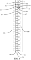
- the linear generator 50 is designed as a module which can be combined in parallel or series as shown in the detailed view of Figure 5 by mechanically linking a plurality of stators 52 in series such that lateral edges 53 of the stators are flush with one-another creating a single electric machine suitable for the maximum force requirement of the specific WEC.
- a translator 54 having a plurality of modules 55 is mechanically connected at lateral edges 56 of the modules to form a single mechanical body matching the length of the stators plus excess length 59 in a direction of oscillatory travel 58 which is determined to meet the desired stroke length requirement of the WEC.
- the translator 54 is connected to the wave activated floating body 12 with an arm or rod 36 (seem in Figure 1 ) while the stators 52 are linked to the reaction body 16.
- the linear generator 50 is specifically a Vernier Effect Permanent Magnet linear Generator (VPMLG).
- VMLG Vernier Effect Permanent Magnet linear Generator
- This machine is a permanent magnet synchronous electrical machine that utilizes higher order space harmonics of the magnetic field in the air gap 61 due to multiphase stator winding currents that are contained in open slots 67 at the air gap surface of the stators 52.
- Standard or conventional permanent magnet synchronous machines employ only the fundamental component of the air gap magnetic field due to the slotted stator winding currents.
- the present implementation has a dual stator permanent magnet linear generator, with stators 52 providing coils on both sides of a central permanent magnet translator 54.
- the translator 54 is formed by a stack of alternating electrical steel laminations 62 and permanent magnets 64 forming the translator modules 55 which are joined by supports 66 which are interconnected to the rod 36.
- the permanent magnets 64 are oriented with their poles facing the direction of travel 58 rather than facing the face of the stator modules. In the exemplary implementation the poles alternate polarity orientation.
- the stators 52 are maintained in two separate pluralities in opposing stator supports 68a and 68b and are offset from one another on opposing sides by one half slot pitch. Stator supports 68a and 68b are supported by or rigidly connected to structure of the reaction body 16 as represented by element 38 in Figure 3 .
- Both sets of stators 52 on the opposing stator supports 68a, 68b utilize the common translator 54 in order to optimally engage the magnetic flux. While the translator modules 55 are shown in Figure 5 as evenly dimensioned with the stators 52 for convenience in depiction, the translator modules 55 are cyclically offset from the stators 52 as shown in Figure 6 in the exemplary implementation employing a VPMLG.
- the linear generator 50 is driven by the low level controller 32 and power electronics 34 as a single machine.
- the stators employed in the linear generator are driven individually or in sub-sets to achieve improved thermal operating characteristics.
- An example arrangement of two power electronics drives 72 and 74 operating two sets of a number of linear generator stators (identified as ⁇ and ⁇ ) is depicted in Figure 7 .
- the two subsets (1 ⁇ , 2 ⁇ ... n ⁇ and 1 ⁇ , 2 ⁇ ... n ⁇ ) of stators 52 supported in the opposing stator supports 68a and 68b, can be controlled independently to drive a single translator 54 between the two stator supports.
- Drive ⁇ 72 is shown driving the ⁇ stators in parallel and drive ⁇ 74 is shown driving the ⁇ stators in parallel schematically in Figure 7 which may be accomplished by mechanical connection or by controlled electrical connection. Alternatively, the mechanical connection or controlled electrical connection may be employed to drive the stators 52 in series.
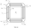
- a plurality of linear generators 50a, 50b, 50c and 50d may be supported within the reaction body 16. The orientation and number of linear generators may be varied to accommodate space available within the reaction body 16 and to take advantage of various cooling scenarios for the stators.
- the arrangement of stators supports 68a (outside) and 68b (inside) in the example shown in Figure 8 would result in greater cooling capability for the outer stators that can conduct heat out to the water 14 through the housing 82 of the reaction body 16 compared to the inner stators that only have an internal volume 84 containing air with which to cool.
- the low level controller 32 can use a thermal sensor input, T, from the linear generator sensors 31 to determine how much current to apply to each of the stator sets in order to achieve to desired change in power take-off force commanded by the high level controller 30 while maintaining thermal equilibrium between the stators modules 52 on the outside and inside stator supports 62a and 62b.
- T thermal sensor input
- the linear generators may be electrically connected in parallel or in series as previously described. In certain implementations, the linear generators may be aligned and mechanically interconnected in series.
Landscapes
- Engineering & Computer Science (AREA)
- Chemical & Material Sciences (AREA)
- Combustion & Propulsion (AREA)
- Mechanical Engineering (AREA)
- General Engineering & Computer Science (AREA)
- Power Engineering (AREA)
- Other Liquid Machine Or Engine Such As Wave Power Use (AREA)
- Linear Motors (AREA)
Description
- This application claims priority of
US provisional application serial no. 62/621,377 filed on 01/24/2018 - The present invention relates to the extraction of electrical power from a linear oscillatory mechanical input with multiple frequency components, more specifically for use as a power take-off of an ocean Wave Energy Converter (WEC).
- There is a vast resource of energy within the world's oceans. This energy is embodied in currents, thermal gradients, or as is of principal interest of this invention, wave motion. A device capable of economically extracting the energy of ocean waves would be capable of providing a significant portion of the world's energy needs if widely deployed. Experimental devices exist and are known as Wave Energy Converters (WECs).
- A WEC Power Take-off (PTO) is the means of extracting mechanical energy from the ocean and converting it into electrical energy. Such a system includes both software (controls) and hardware (gearboxes, linkages, powertrains, generators, etc.). WECs have often been equipped with relatively simple controllers, providing a mechanical damping coefficient to maximize power from the dominant wave frequency only. On the hardware side, WEC PTOs often implement hydraulics as a method of transmitting and converting linear motion induced by wave energy extraction.
- Wave Energy Converters face significant technical and economic challenges because Wave Energy, unlike other renewables, must be collected from an extremely dynamic resource. Ocean waves are not a simple, single frequency wave, but rather the superposition of countless frequency and amplitude waves. As a result, a Wave Energy Converter must be able to extract energy efficiently from a wide frequency spectrum and change operating conditions on a second, or sub-second time scale for maximum energy extraction.
-
US 2007/0261404 A1 discloses active impedance matching systems (AIMS) and methods for increasing the efficiency of a wave energy converter having a shaft and a shell intended to be placed in a body of water and to move relative to each other in response to forces applied to the WEC by the body of water. The system includes apparatus for: (a) extracting energy from the WEC and producing output electric energy as a function of the movement of the shell (shaft) relative to the shaft (shell): and (b) for selectively imparting energy to one of the shell and shaft for causing an increase in the displacement and velocity (or acceleration) of one of the shell and shaft relative to the other, whereby the net amount of output electrical energy produced is increased. The apparatus for extracting energy and for selectively supplying energy may be implemented using a single device capable of being operated bi-directionally, in terms of both direction and force, or may be implemented by different devices. - The present invention relates to a wave energy converter according to claim 1 and a method for wave energy conversion employing a wave energy converter according to claim 7. The wave Energy Converter (WEC) Power take-off (PTO) is designed to utilize both software and hardware to extract greater amounts of electrical energy from ocean waves than can be achieved through existing means. The invention comprises a linear electric motor-generator combined with both low level and high level control systems. The high level control system dictates a desired operational state for the linear electric motor-generator which is achieved through the usage of a low level control system. The linear electric motor-generator is a machine designed for the purpose of achieving high energy conversion efficiencies in the operating states of the WEC and subsequent high level control system.
- Embodiments of the invention result from the dependent claims and the following exemplary embodiments.
- In one implementation of this invention, the linear electric motor-generator comprises a Vernier Effect Permanent Magnet Linear Generator while the high level control system utilizes a reactive control approach.
- The present may be better understood, and its numerous features and advantages made apparent to those skilled in the art by referencing the accompanying drawings. For ease of understanding and simplicity, common numbering of elements is employed where an element is the same in different drawings.
-
Figure 1 is a side view of an example Wave Energy Converter incorporating an implementation of a PTO system; -
Figure 2 is an example time series of a typical operating sea state; -
Figure 3 is a block diagram of the PTO system integrated with an example WEC system; -
Figure 4 is a block diagram of the high level controller; -
Figure 5 is detailed view of the stator and translator modules forming a complete linear electric motor generator; -
Figure 6 is an overall depiction of the Vernier permanent magnet linear generator structure; -
Figure 7 is a diagram of the power electronics and stator connections; -
Figure 8 is a drawing depicting an example physical arrangement of linear generators within a sealed housing from a top view; - The following is a detailed description of illustrative implementations of the present invention. As these implementations of the present invention are described with reference to the aforementioned drawings, various modifications or adaptations of the methods and or specific structures described may become apparent to those skilled in the art. For example, the device set forth herein has been characterized as a Wave Energy Converter Power Take-off, but it is apparent that other uses may be found for this device. Hence, these drawings and descriptions are not to be considered in a limiting sense as it is understood that the present invention is in no way limited to the implementations illustrated.
- The implementations presently disclosed provide a Power Take-off (PTO) system for use in an ocean Wave Energy Converter (WEC). For purposes of illustration, an example two body WEC is presented in
Figure 1 . This is a point-absorber type WEC 10 with capability of extracting energy in a vertical, heave, direction. A wave activatedfloating body 12 oscillates in the heave direction (as represented by arrow 13) as force (depicted by arrow 15) is imparted upon it by the waves in the ocean water depicted aselement 14. Anexemplary time series 20 of the motion of thewater waves 14 is depicted in the graph ofFigure 2 . The floatingbody 12 is engaged by and reacts against areaction body 16 which is either static or oscillating out of phase relative to the floating body. The forces between the two bodies are transmitted through aPTO device 18. Most WEC PTOs are either limited by a lack of optimal controls, a lack of capability in their generator and power train system, or both. - In the case of a lack of control, the high level control of the WEC does not have the sufficient formulation or information to predict and command the optimal operating state for the generator and power train system. For example, a controller that is designed to sense the dominant frequency component of a sea state and command a desired damping value for the generator does not have the capability to command the generator to optimally extract power from any frequency components other than the detected dominant frequency. Moreover, the controller may not have adequate sensor information to even be aware of the energy available in other wave frequency components.
Figure 2 is presented to provide a visual understanding of a time series of a typical operating sea state containing multiple frequency components. - In the case of a lack of capability of a generator and power train system, even if the controller had perfect information relating to the optimal operating state of the generator at present and in the short-term future, the generator and power train system may not be capable to act on such information. For example, if a controller wished to command a certain generator and power train system to quickly change operating state in order to capture available energy in an upcoming higher frequency component of a wave, the generator and power train system may have excessive inertia or insufficient operating force capability to change operating state in a timely manner.
- The presently disclosed implementation solves these problems by utilizing an entire, integrated Power Take-off system containing a purpose built high level control, low level control, power train, and electrical generator all working together optimally. The full system is outlined as it would be utilized in the
example WEC 10 fromFigure 1 in the block diagram ofFigure 3 . In an exemplary implementation, a direct drive linear electric generator 50 (to be described in greater detail subsequently with respect toFigures 5 and6 ) is utilized in thePTO 18, and therefore the power train and generator are consolidated into a single element with no need for a gearbox or transmission. As can be seen inFigure 3 , the implementation disclosed incorporates several components, each of which will be described with their interactions with the other subcomponents outlined. - A
high level controller 30, such as a computer having either a general purpose processor or single purpose processor utilizing one or more cores with areadable memory 41, for processing calculation modules (which may be implemented in hardware or software subroutines). Thehigh level controller 30 contains several modules as shown inFigure 4 . Specifically, thehigh level controller 30 contains anestimator block 42, aprediction block 44, and acontrol block 46. Further, thecontrol block 46 includes amodel 48 of theWEC 10 and thelinear generator 50 including the mass and hydrodynamic properties of each body. One ormore sensors 31 associated with thelinear generator 50 transmit a signal to thehigh level controller 30 which includes the present force (Fpto) applied between thelinear generator 50 and the wave activated floatingbody 12, the position (z) of atranslator 54 relative to one ormore stators 52 of thelinear generator 50 and the rate of change of this position (dz). This data is collected and stored in the computerreadable memory 41 which can be accessed by thehigh level controller 30, creating a data store of time indexed sensor values. While Fpto and z must be transmitted to thehigh level controller 30, dz may also be calculated based on the time series data of z. - The
estimator block 42 uses Fpto, z, and dz along with knowledge of the Wave Energy Converter's physical properties to calculate the estimated excitation force (Fe) impacted upon the wave activated body by the sea. - The
prediction block 44 uses the time series history of Fe output by theestimator block 42 as an input to an auto-regressive model to calculate a prediction of future Fe over a specified time horizon. - Finally, the
control block 46 uses the future prediction of Fe output from theprediction block 44 with the current states of z and dz as transmitted from thelinear generator sensors 31, and thenumerical model 48 of the WEC and linear electric generator to predict the WEC and linear generator's response to the future excitation force imparted by the wave action the ocean water. With the ability to model the future response of the WEC given the predicted Fe over a certain time horizon, thecontrol block 46 then utilizes an optimization function to select a set of change of PTO force (dFPTO) commands over a specified time horizon to maximize electrical power extraction. The commanded dFPTO is then sent to thelow level controller 32. - As represented in
Figure 3 , thelow level controller 32 receives thehigh level controller 30 andlinear generator sensors 31 outputs, and then computes and commands appropriate action from thepower electronics 34 which in turn drive thelinear generator 50. - The
linear generator 50 is capable of acting on the desired control commands in order to achieve optimal power extraction performance of the WEC system. The general nature of these control commands is highly variable in operational state from second to second and typically requiring high force at low speed with operation in two physical directions and operating as both a motor and a generator for a total of four quadrants of control. Thelinear generator 50 in the disclosed implementation is a direct drive permanent magnet linear generator which receives control commands and adapts to new operating states on a sub-second time scale. Thelinear generator 50 is designed as a module which can be combined in parallel or series as shown in the detailed view ofFigure 5 by mechanically linking a plurality ofstators 52 in series such that lateral edges 53 of the stators are flush with one-another creating a single electric machine suitable for the maximum force requirement of the specific WEC. Similarly, atranslator 54 having a plurality ofmodules 55 is mechanically connected atlateral edges 56 of the modules to form a single mechanical body matching the length of the stators plusexcess length 59 in a direction ofoscillatory travel 58 which is determined to meet the desired stroke length requirement of the WEC. For the exemplary implementation, thetranslator 54 is connected to the wave activated floatingbody 12 with an arm or rod 36 (seem inFigure 1 ) while thestators 52 are linked to thereaction body 16. - In one implementation of this invention, the
linear generator 50 is specifically a Vernier Effect Permanent Magnet linear Generator (VPMLG). This machine, as depicted inFigure 6 , is a permanent magnet synchronous electrical machine that utilizes higher order space harmonics of the magnetic field in theair gap 61 due to multiphase stator winding currents that are contained inopen slots 67 at the air gap surface of thestators 52. Standard or conventional permanent magnet synchronous machines employ only the fundamental component of the air gap magnetic field due to the slotted stator winding currents. By contrast, the present implementation has a dual stator permanent magnet linear generator, withstators 52 providing coils on both sides of a centralpermanent magnet translator 54. Thetranslator 54 is formed by a stack of alternatingelectrical steel laminations 62 andpermanent magnets 64 forming thetranslator modules 55 which are joined bysupports 66 which are interconnected to therod 36. Thepermanent magnets 64 are oriented with their poles facing the direction oftravel 58 rather than facing the face of the stator modules. In the exemplary implementation the poles alternate polarity orientation. Thestators 52 are maintained in two separate pluralities in opposing stator supports 68a and 68b and are offset from one another on opposing sides by one half slot pitch. Stator supports 68a and 68b are supported by or rigidly connected to structure of thereaction body 16 as represented byelement 38 inFigure 3 . Both sets ofstators 52 on the opposing stator supports 68a, 68b utilize thecommon translator 54 in order to optimally engage the magnetic flux. While thetranslator modules 55 are shown inFigure 5 as evenly dimensioned with thestators 52 for convenience in depiction, thetranslator modules 55 are cyclically offset from thestators 52 as shown inFigure 6 in the exemplary implementation employing a VPMLG. - In one implementation of this invention the
linear generator 50 is driven by thelow level controller 32 andpower electronics 34 as a single machine. In an alternate implementation of the invention the stators employed in the linear generator are driven individually or in sub-sets to achieve improved thermal operating characteristics. An example arrangement of two power electronics drives 72 and 74 operating two sets of a number of linear generator stators (identified as α and β) is depicted inFigure 7 . In this arrangement the two subsets (1 α, 2 α ... n α and 1 β, 2 β ... n β) ofstators 52 supported in the opposing stator supports 68a and 68b, can be controlled independently to drive asingle translator 54 between the two stator supports. Driveα 72 is shown driving the α stators in parallel and drive β 74 is shown driving the β stators in parallel schematically inFigure 7 which may be accomplished by mechanical connection or by controlled electrical connection. Alternatively, the mechanical connection or controlled electrical connection may be employed to drive thestators 52 in series. As show inFigure 8 a plurality oflinear generators reaction body 16 and to take advantage of various cooling scenarios for the stators. The arrangement of stators supports 68a (outside) and 68b (inside) in the example shown inFigure 8 would result in greater cooling capability for the outer stators that can conduct heat out to thewater 14 through thehousing 82 of thereaction body 16 compared to the inner stators that only have aninternal volume 84 containing air with which to cool. Thelow level controller 32 can use a thermal sensor input, T, from thelinear generator sensors 31 to determine how much current to apply to each of the stator sets in order to achieve to desired change in power take-off force commanded by thehigh level controller 30 while maintaining thermal equilibrium between thestators modules 52 on the outside and inside stator supports 62a and 62b. The overall result of this is an improved capability of the whole PTO system as allstators 52 are no longer limited by the stators with the poorest cooling capability. - The implementation shown in
Figure 8 while shown with thetranslators 54 of thelinear generators body 12 andreaction body 16, the linear generators may be electrically connected in parallel or in series as previously described. In certain implementations, the linear generators may be aligned and mechanically interconnected in series. - While the invention has been described with reference to specific implementations, it will be understood by those skilled in the art that various changes may be made and equivalents may be substituted for elements thereof without departing from the scope of the invention. In addition, modifications may be made without departing from the essential teachings of the invention as defined in the following claims.
Claims (9)
- A wave energy converter comprising:a floating body (12);a reaction body (16) engaging the floating body, said reaction body static or oscillating out of phase relative to the floating body;a power take-off (PTO) (18) havingat least one direct drive linear generator (50) comprisinga plurality of stators (52) linked in series having lateral edges flush (53) with one-another creating a single electric machine; anda translator (54) having a plurality of translator modules, a stack of alternating electrical steel laminations (62) and permanent magnets (64) forming the plurality of translator modules, said plurality of translator modules mechanically connected at lateral edges of the translator by supports (66) and matching the length of the linked stators plus an excess length in a direction of oscillatory travel determined to meet a desired stroke length of the direct drive linear generator, said PTO interconnected to a rod engaging the floating body;a high level controller (30) responsive to one or more sensors (31) engaged to the direct drive linear generator wherein the high level controller contains an estimator block (42), a prediction block (44), and a control block (46), said control block including a model of the WEC and the linear generator (48) including the mass and hydrodynamic properties of each body and wherein the one or more sensors (31) associated with the linear generator transmit signals to the high level controller which include a present force (FPTO) applied between the linear generator and the floating body, a position (z) of the translator relative to the plurality of stators of the linear generator and a rate of change of the position 30 (dz), the high level controller providing a PTO force change command (dFPTO) responsive to multiple frequency components of a sea state calculated as an estimated excitation force (Fe) and calculated prediction of future Fe over a specified time horizon;a low level controller (32) receiving the PTO force change command and providing one or more control signals to one or more power electronics (34) connected to the direct drive linear generator, said direct drive linear generator operable responsive to the one or more control signals to achieve optimal power extraction performance with high force at low speed with operation in two physical directions and operating as both a motor and a generator for a total of four quadrants of control.
- The wave energy converter as defined in claim 1 wherein the at least one direct drive linear generator comprises a plurality of direct drive linear generators (50a, 50b, 50c, 50d), said plurality of direct drive linear generators mechanically connected in parallel between the floating body and the reaction body.
- The wave energy converter as defined in claim 1 wherein the stators in the plurality of stators comprise a first plurality of stators mounted in a first stator support (68a) and a second plurality of stators mounted in a second opposing stator support (68b), said first and second opposing stator supports maintaining the first and second plurality of stators offset by a one half slot pitch.
- The wave energy converter as defined in claim 3 wherein the first plurality of stators and second plurality of stators are separately driven by the one or more power electronics.
- The wave energy converter as defined in claim 4 wherein the first plurality of stators and second plurality of stators are driven with different currents determined to provide a thermal equilibrium.
- The wave energy converter as defined in claim 3 wherein the stator supports are supported by or rigidly connected to a structure of the reaction body and the translator is connected to the floating body.
- A method for wave energy conversion employing a wave energy converter as defined in claim 1, the method comprising:buoyantly supporting the floating body on a water surface;engaging the floating body with the reaction body, said reaction body static or oscillating out of phase relative to the floating body;engaging the floating body with the rod interconnected to the at least one linear generator in a power take off (PTO),engaging the plurality of stators to the reaction body for translation of the translator within the stators; andextracting electrical power from the PTO.
- The method for wave energy conversion of claim 7 wherein the at least one linear generator comprises a plurality of linear generators and further comprising electrically connecting the plurality of linear generators in series.
- The method for wave energy conversion of claim 7 wherein the at least one linear generator comprises a plurality of linear generators and further comprising electrically connecting the plurality of linear generators in parallel.
Applications Claiming Priority (3)
| Application Number | Priority Date | Filing Date | Title |
|---|---|---|---|
| US201862621377P | 2018-01-24 | 2018-01-24 | |
| US16/253,118 US10865763B2 (en) | 2018-01-24 | 2019-01-21 | Power take-off for a wave energy converter |
| PCT/US2019/014639 WO2019147599A1 (en) | 2018-01-24 | 2019-01-22 | Power take-off for a wave energy converter |
Publications (3)
| Publication Number | Publication Date |
|---|---|
| EP3743619A1 EP3743619A1 (en) | 2020-12-02 |
| EP3743619A4 EP3743619A4 (en) | 2021-06-23 |
| EP3743619B1 true EP3743619B1 (en) | 2024-04-10 |
Family
ID=67298542
Family Applications (1)
| Application Number | Title | Priority Date | Filing Date |
|---|---|---|---|
| EP19743158.8A Active EP3743619B1 (en) | 2018-01-24 | 2019-01-22 | Power take-off for a wave energy converter |
Country Status (3)
| Country | Link |
|---|---|
| US (1) | US10865763B2 (en) |
| EP (1) | EP3743619B1 (en) |
| WO (1) | WO2019147599A1 (en) |
Families Citing this family (5)
| Publication number | Priority date | Publication date | Assignee | Title |
|---|---|---|---|---|
| US10855159B1 (en) * | 2020-02-27 | 2020-12-01 | John Sabah Gewarges | Coil regeneration device and method of use |
| CN112953114B (en) * | 2021-02-22 | 2022-09-06 | 南京工程学院 | A variable stiffness wave power generation system and its optimal control method |
| EP4367385A4 (en) * | 2021-07-09 | 2025-08-27 | Dehlsen Ass Llc | LINEAR UNIVERSAL MODULAR ABSORBER FOR WAVE ENERGY CONVERSION |
| CN113898521B (en) * | 2021-09-22 | 2024-03-08 | 鲁东大学 | Marine floating platform stand damping heave plate and wave energy collection device |
| CN117386548B (en) * | 2023-11-27 | 2024-02-27 | 华南理工大学 | A kinetic energy recovery wind and wave integrated system |
Family Cites Families (34)
| Publication number | Priority date | Publication date | Assignee | Title |
|---|---|---|---|---|
| US378507A (en) * | 1888-02-28 | henderson | ||
| US6020653A (en) * | 1997-11-18 | 2000-02-01 | Aqua Magnetics, Inc. | Submerged reciprocating electric generator |
| SE520921C2 (en) * | 2002-01-10 | 2003-09-16 | Swedish Seabased Energy Ab | Wave power unit for generation of electricity has a float that moves with the waves and is mechanically coupled to a linear generator |
| US8105052B1 (en) * | 2002-06-24 | 2012-01-31 | Hill Jr Richard Newton | Wave and tide actuated renewable energy pump |
| SE523000C2 (en) * | 2003-03-27 | 2004-03-23 | Swedish Seabased Energy Ab | Wave power unit |
| US6812588B1 (en) * | 2003-10-21 | 2004-11-02 | Stephen J. Zadig | Wave energy converter |
| AU2005206866B2 (en) | 2004-01-14 | 2011-02-03 | Ocean Power Technologies, Inc. | Active impedance matching systems and methods for wave energy converter |
| US7362003B2 (en) * | 2004-03-16 | 2008-04-22 | Ocean Power Technologies, Inc. | Coil switching circuit for linear electric generator |
| US7493759B2 (en) * | 2004-11-15 | 2009-02-24 | The Regents Of The University Of Michigan | Fluid motion energy converter |
| US7323790B2 (en) | 2005-03-15 | 2008-01-29 | Ocean Power Technologies, Inc. | Wave energy converters (WECs) with linear electric generators (LEGs) |
| US7573170B2 (en) * | 2005-10-05 | 2009-08-11 | Novatorque, Inc. | Motor modules for linear and rotary motors |
| US7960851B2 (en) * | 2006-04-21 | 2011-06-14 | Van Huffel Phillip L | Power generator and method for generating power |
| EP2029890B1 (en) * | 2006-05-30 | 2016-01-27 | Triple X Energy Inc. | Wave energy converter |
| PL2134960T3 (en) * | 2007-04-18 | 2017-06-30 | Seabased Ab | A wave power unit, a buoy, use of a wave power unit and a method for producing electric energy |
| US8482145B2 (en) | 2007-11-19 | 2013-07-09 | Ocean Energy Management Limited | Ocean energy system and method |
| US10393089B2 (en) * | 2013-04-05 | 2019-08-27 | Oscilla Power Inc. | Wave energy converter |
| ES2676818T3 (en) * | 2008-08-26 | 2018-07-25 | Seabased Ab | A unit of wave power |
| CA2734602C (en) * | 2008-08-28 | 2016-01-05 | Seabased Ab | A wave-power unit, and a use of a such |
| WO2010076617A2 (en) | 2009-01-05 | 2010-07-08 | Dehlsen Associates, L.L.C. | Method and apparatus for converting ocean wave energy into electricity |
| NO331113B1 (en) * | 2010-03-23 | 2011-10-10 | Norwegian Ocean Power As | Variable electric generator |
| BR112012030277B1 (en) * | 2010-05-28 | 2021-11-16 | Seabased Ab | LINEAR GENERATOR FOR SUBMERGED USE AND METHOD FOR ELECTRIC ENERGY PRODUCTION |
| BR112012030280A2 (en) * | 2010-05-28 | 2016-08-09 | Seabased Ab | wave energy production unit comprising a guide device |
| EP2577046B1 (en) * | 2010-05-28 | 2018-07-04 | Seabased AB | A wave power unit, a use of a such and a method of producing electric energy |
| GB2486279B (en) * | 2010-12-10 | 2013-11-06 | Trident Energy Ltd | Wave energy converter |
| US8723355B2 (en) * | 2011-03-28 | 2014-05-13 | Ocean Power Technologies | Autonomously operated buoys with power generation and power usage control |
| CN202503419U (en) | 2011-12-27 | 2012-10-24 | 东南大学 | Vernier linear motor for direct drive wave power generation |
| CN102437702A (en) | 2011-12-27 | 2012-05-02 | 东南大学 | Vernier linear motor for direct drive wave power generation |
| US10011910B2 (en) * | 2012-10-29 | 2018-07-03 | Energystics, Ltd. | Linear faraday induction generator for the generation of electrical power from ocean wave kinetic energy and arrangements thereof |
| US9624900B2 (en) * | 2012-10-29 | 2017-04-18 | Energystics, Ltd. | Linear faraday induction generator for the generation of electrical power from ocean wave kinetic energy and arrangements thereof |
| US8967693B2 (en) | 2013-03-14 | 2015-03-03 | San Jamar, Inc. | Materials scoop |
| US9074577B2 (en) | 2013-03-15 | 2015-07-07 | Dehlsen Associates, Llc | Wave energy converter system |
| US9595858B2 (en) | 2013-09-09 | 2017-03-14 | Wisconsin Alumni Research Foundation | Double air gap, spoke type vernier machine |
| US10427913B2 (en) | 2013-12-05 | 2019-10-01 | Otis Elevator Company | Linear propulsion system |
| WO2015176057A1 (en) * | 2014-05-16 | 2015-11-19 | Renerge, Inc. | Fluid flow induced oscillating energy harvester with variable damping based upon oscillation amplitude |
-
2019
- 2019-01-21 US US16/253,118 patent/US10865763B2/en active Active
- 2019-01-22 EP EP19743158.8A patent/EP3743619B1/en active Active
- 2019-01-22 WO PCT/US2019/014639 patent/WO2019147599A1/en not_active Ceased
Also Published As
| Publication number | Publication date |
|---|---|
| EP3743619A1 (en) | 2020-12-02 |
| US20190226444A1 (en) | 2019-07-25 |
| WO2019147599A1 (en) | 2019-08-01 |
| EP3743619A4 (en) | 2021-06-23 |
| US10865763B2 (en) | 2020-12-15 |
Similar Documents
| Publication | Publication Date | Title |
|---|---|---|
| US10865763B2 (en) | Power take-off for a wave energy converter | |
| US10871141B2 (en) | Vernier permanent magnet linear generator | |
| Dai et al. | A wave energy harvesting system based on the double-wing flywheel for unmanned surface vessels | |
| JP5295502B2 (en) | Active impedance matching system and method for wave energy converter | |
| AU2016200649B2 (en) | Natural frequency adjustment mechanism for wave-power generator | |
| Farrok et al. | Design and optimization of a novel dual-port linear generator for oceanic wave energy conversion | |
| US20120139261A1 (en) | Wave energy conversion system | |
| Faiad et al. | Linear generator technologies for wave energy conversion applications: A review | |
| CN119590579A (en) | A wave energy integration device based on multi-resonance motion control | |
| Yin et al. | Dynamic characteristics and test results of a wave power takeoff system with mechanical motion rectification and transmission | |
| EP3887669B1 (en) | A vernier permanent magnet linear generator | |
| Baker et al. | All electric drive train for wave energy power take off | |
| Yin et al. | Mechanical motion rectifier based efficient power takeoff for ocean wave energy harvesting | |
| Xiang et al. | Control requirements of direct drive wave energy converters | |
| Li et al. | Maximum power point tracking control of a linear magnetic-geared generator for direct-drive wave energy conversion | |
| Xuereb et al. | Design of a linear electrical machine for a wave generation system in the Maltese waters | |
| Ridge et al. | Dynamic test rig for linear generators intended for wave-power applications | |
| CN116800018A (en) | A power generation system and adaptive method based on asynchronously amplified vibration of inertial components | |
| Takemura et al. | Investigation of the Number of Poles of SPMSG and Speed Increase Ratio for High Efficiency in Direct-link Wave Power Generation System | |
| CN120281144A (en) | Method and device for generating reciprocating mechanical energy by utilizing fluid kinetic energy | |
| Sang | A suboptimal control strategy for a slider crank wave energy converter power take-off system | |
| Li et al. | Complex-conjugate control of a linear magnetic-geared permanent-magnet machine for Archimedes wave swing based power generation | |
| Sharkh et al. | An inertial coupled marine power generator for small boats | |
| Li et al. | Maximum power point tracking control of a linear magnetic | |
| Jobanputra et al. | Modelling and Control of a Point Absorber Wave Energy Converter |
Legal Events
| Date | Code | Title | Description |
|---|---|---|---|
| STAA | Information on the status of an ep patent application or granted ep patent |
Free format text: STATUS: THE INTERNATIONAL PUBLICATION HAS BEEN MADE |
|
| PUAI | Public reference made under article 153(3) epc to a published international application that has entered the european phase |
Free format text: ORIGINAL CODE: 0009012 |
|
| STAA | Information on the status of an ep patent application or granted ep patent |
Free format text: STATUS: REQUEST FOR EXAMINATION WAS MADE |
|
| 17P | Request for examination filed |
Effective date: 20200812 |
|
| AK | Designated contracting states |
Kind code of ref document: A1 Designated state(s): AL AT BE BG CH CY CZ DE DK EE ES FI FR GB GR HR HU IE IS IT LI LT LU LV MC MK MT NL NO PL PT RO RS SE SI SK SM TR |
|
| AX | Request for extension of the european patent |
Extension state: BA ME |
|
| RIN1 | Information on inventor provided before grant (corrected) |
Inventor name: MCCLEER, PATRICK J. Inventor name: MCCALL, ALAN L. |
|
| DAV | Request for validation of the european patent (deleted) | ||
| DAX | Request for extension of the european patent (deleted) | ||
| REG | Reference to a national code |
Ref legal event code: R079 Ref country code: DE Ref legal event code: R079 Ref document number: 602019050017 Country of ref document: DE Free format text: PREVIOUS MAIN CLASS: F03B0013120000 Ipc: F03B0013200000 |
|
| A4 | Supplementary search report drawn up and despatched |
Effective date: 20210525 |
|
| RIC1 | Information provided on ipc code assigned before grant |
Ipc: F03B 13/20 20060101AFI20210518BHEP Ipc: F03B 13/18 20060101ALI20210518BHEP Ipc: F03B 15/00 20060101ALI20210518BHEP Ipc: H02K 7/18 20060101ALI20210518BHEP Ipc: H02K 35/02 20060101ALI20210518BHEP |
|
| STAA | Information on the status of an ep patent application or granted ep patent |
Free format text: STATUS: EXAMINATION IS IN PROGRESS |
|
| 17Q | First examination report despatched |
Effective date: 20230220 |
|
| GRAP | Despatch of communication of intention to grant a patent |
Free format text: ORIGINAL CODE: EPIDOSNIGR1 |
|
| STAA | Information on the status of an ep patent application or granted ep patent |
Free format text: STATUS: GRANT OF PATENT IS INTENDED |
|
| INTG | Intention to grant announced |
Effective date: 20231130 |
|
| GRAS | Grant fee paid |
Free format text: ORIGINAL CODE: EPIDOSNIGR3 |
|
| GRAA | (expected) grant |
Free format text: ORIGINAL CODE: 0009210 |
|
| STAA | Information on the status of an ep patent application or granted ep patent |
Free format text: STATUS: THE PATENT HAS BEEN GRANTED |
|
| AK | Designated contracting states |
Kind code of ref document: B1 Designated state(s): AL AT BE BG CH CY CZ DE DK EE ES FI FR GB GR HR HU IE IS IT LI LT LU LV MC MK MT NL NO PL PT RO RS SE SI SK SM TR |
|
| REG | Reference to a national code |
Ref country code: GB Ref legal event code: FG4D |
|
| REG | Reference to a national code |
Ref country code: CH Ref legal event code: EP |
|
| REG | Reference to a national code |
Ref country code: DE Ref legal event code: R096 Ref document number: 602019050017 Country of ref document: DE |
|
| REG | Reference to a national code |
Ref country code: IE Ref legal event code: FG4D |
|
| REG | Reference to a national code |
Ref country code: LT Ref legal event code: MG9D |
|
| REG | Reference to a national code |
Ref country code: NL Ref legal event code: MP Effective date: 20240410 |
|
| REG | Reference to a national code |
Ref country code: AT Ref legal event code: MK05 Ref document number: 1675137 Country of ref document: AT Kind code of ref document: T Effective date: 20240410 |
|
| PG25 | Lapsed in a contracting state [announced via postgrant information from national office to epo] |
Ref country code: NL Free format text: LAPSE BECAUSE OF FAILURE TO SUBMIT A TRANSLATION OF THE DESCRIPTION OR TO PAY THE FEE WITHIN THE PRESCRIBED TIME-LIMIT Effective date: 20240410 |
|
| PG25 | Lapsed in a contracting state [announced via postgrant information from national office to epo] |
Ref country code: NL Free format text: LAPSE BECAUSE OF FAILURE TO SUBMIT A TRANSLATION OF THE DESCRIPTION OR TO PAY THE FEE WITHIN THE PRESCRIBED TIME-LIMIT Effective date: 20240410 |
|
| PG25 | Lapsed in a contracting state [announced via postgrant information from national office to epo] |
Ref country code: IS Free format text: LAPSE BECAUSE OF FAILURE TO SUBMIT A TRANSLATION OF THE DESCRIPTION OR TO PAY THE FEE WITHIN THE PRESCRIBED TIME-LIMIT Effective date: 20240810 |
|
| PG25 | Lapsed in a contracting state [announced via postgrant information from national office to epo] |
Ref country code: BG Free format text: LAPSE BECAUSE OF FAILURE TO SUBMIT A TRANSLATION OF THE DESCRIPTION OR TO PAY THE FEE WITHIN THE PRESCRIBED TIME-LIMIT Effective date: 20240410 |
|
| PG25 | Lapsed in a contracting state [announced via postgrant information from national office to epo] |
Ref country code: FI Free format text: LAPSE BECAUSE OF FAILURE TO SUBMIT A TRANSLATION OF THE DESCRIPTION OR TO PAY THE FEE WITHIN THE PRESCRIBED TIME-LIMIT Effective date: 20240410 Ref country code: HR Free format text: LAPSE BECAUSE OF FAILURE TO SUBMIT A TRANSLATION OF THE DESCRIPTION OR TO PAY THE FEE WITHIN THE PRESCRIBED TIME-LIMIT Effective date: 20240410 |
|
| PG25 | Lapsed in a contracting state [announced via postgrant information from national office to epo] |
Ref country code: GR Free format text: LAPSE BECAUSE OF FAILURE TO SUBMIT A TRANSLATION OF THE DESCRIPTION OR TO PAY THE FEE WITHIN THE PRESCRIBED TIME-LIMIT Effective date: 20240711 |
|
| PG25 | Lapsed in a contracting state [announced via postgrant information from national office to epo] |
Ref country code: PT Free format text: LAPSE BECAUSE OF FAILURE TO SUBMIT A TRANSLATION OF THE DESCRIPTION OR TO PAY THE FEE WITHIN THE PRESCRIBED TIME-LIMIT Effective date: 20240812 |
|
| PG25 | Lapsed in a contracting state [announced via postgrant information from national office to epo] |
Ref country code: ES Free format text: LAPSE BECAUSE OF FAILURE TO SUBMIT A TRANSLATION OF THE DESCRIPTION OR TO PAY THE FEE WITHIN THE PRESCRIBED TIME-LIMIT Effective date: 20240410 |
|
| PG25 | Lapsed in a contracting state [announced via postgrant information from national office to epo] |
Ref country code: AT Free format text: LAPSE BECAUSE OF FAILURE TO SUBMIT A TRANSLATION OF THE DESCRIPTION OR TO PAY THE FEE WITHIN THE PRESCRIBED TIME-LIMIT Effective date: 20240410 |
|
| PG25 | Lapsed in a contracting state [announced via postgrant information from national office to epo] |
Ref country code: PL Free format text: LAPSE BECAUSE OF FAILURE TO SUBMIT A TRANSLATION OF THE DESCRIPTION OR TO PAY THE FEE WITHIN THE PRESCRIBED TIME-LIMIT Effective date: 20240410 |
|
| PG25 | Lapsed in a contracting state [announced via postgrant information from national office to epo] |
Ref country code: LV Free format text: LAPSE BECAUSE OF FAILURE TO SUBMIT A TRANSLATION OF THE DESCRIPTION OR TO PAY THE FEE WITHIN THE PRESCRIBED TIME-LIMIT Effective date: 20240410 |
|
| PG25 | Lapsed in a contracting state [announced via postgrant information from national office to epo] |
Ref country code: PT Free format text: LAPSE BECAUSE OF FAILURE TO SUBMIT A TRANSLATION OF THE DESCRIPTION OR TO PAY THE FEE WITHIN THE PRESCRIBED TIME-LIMIT Effective date: 20240812 Ref country code: PL Free format text: LAPSE BECAUSE OF FAILURE TO SUBMIT A TRANSLATION OF THE DESCRIPTION OR TO PAY THE FEE WITHIN THE PRESCRIBED TIME-LIMIT Effective date: 20240410 Ref country code: NO Free format text: LAPSE BECAUSE OF FAILURE TO SUBMIT A TRANSLATION OF THE DESCRIPTION OR TO PAY THE FEE WITHIN THE PRESCRIBED TIME-LIMIT Effective date: 20240710 Ref country code: LV Free format text: LAPSE BECAUSE OF FAILURE TO SUBMIT A TRANSLATION OF THE DESCRIPTION OR TO PAY THE FEE WITHIN THE PRESCRIBED TIME-LIMIT Effective date: 20240410 Ref country code: IS Free format text: LAPSE BECAUSE OF FAILURE TO SUBMIT A TRANSLATION OF THE DESCRIPTION OR TO PAY THE FEE WITHIN THE PRESCRIBED TIME-LIMIT Effective date: 20240810 Ref country code: HR Free format text: LAPSE BECAUSE OF FAILURE TO SUBMIT A TRANSLATION OF THE DESCRIPTION OR TO PAY THE FEE WITHIN THE PRESCRIBED TIME-LIMIT Effective date: 20240410 Ref country code: GR Free format text: LAPSE BECAUSE OF FAILURE TO SUBMIT A TRANSLATION OF THE DESCRIPTION OR TO PAY THE FEE WITHIN THE PRESCRIBED TIME-LIMIT Effective date: 20240711 Ref country code: FI Free format text: LAPSE BECAUSE OF FAILURE TO SUBMIT A TRANSLATION OF THE DESCRIPTION OR TO PAY THE FEE WITHIN THE PRESCRIBED TIME-LIMIT Effective date: 20240410 Ref country code: ES Free format text: LAPSE BECAUSE OF FAILURE TO SUBMIT A TRANSLATION OF THE DESCRIPTION OR TO PAY THE FEE WITHIN THE PRESCRIBED TIME-LIMIT Effective date: 20240410 Ref country code: BG Free format text: LAPSE BECAUSE OF FAILURE TO SUBMIT A TRANSLATION OF THE DESCRIPTION OR TO PAY THE FEE WITHIN THE PRESCRIBED TIME-LIMIT Effective date: 20240410 Ref country code: AT Free format text: LAPSE BECAUSE OF FAILURE TO SUBMIT A TRANSLATION OF THE DESCRIPTION OR TO PAY THE FEE WITHIN THE PRESCRIBED TIME-LIMIT Effective date: 20240410 Ref country code: RS Free format text: LAPSE BECAUSE OF FAILURE TO SUBMIT A TRANSLATION OF THE DESCRIPTION OR TO PAY THE FEE WITHIN THE PRESCRIBED TIME-LIMIT Effective date: 20240710 |
|
| REG | Reference to a national code |
Ref country code: DE Ref legal event code: R097 Ref document number: 602019050017 Country of ref document: DE |
|
| PG25 | Lapsed in a contracting state [announced via postgrant information from national office to epo] |
Ref country code: DK Free format text: LAPSE BECAUSE OF FAILURE TO SUBMIT A TRANSLATION OF THE DESCRIPTION OR TO PAY THE FEE WITHIN THE PRESCRIBED TIME-LIMIT Effective date: 20240410 |
|
| PG25 | Lapsed in a contracting state [announced via postgrant information from national office to epo] |
Ref country code: EE Free format text: LAPSE BECAUSE OF FAILURE TO SUBMIT A TRANSLATION OF THE DESCRIPTION OR TO PAY THE FEE WITHIN THE PRESCRIBED TIME-LIMIT Effective date: 20240410 |
|
| PG25 | Lapsed in a contracting state [announced via postgrant information from national office to epo] |
Ref country code: CZ Free format text: LAPSE BECAUSE OF FAILURE TO SUBMIT A TRANSLATION OF THE DESCRIPTION OR TO PAY THE FEE WITHIN THE PRESCRIBED TIME-LIMIT Effective date: 20240410 |
|
| PG25 | Lapsed in a contracting state [announced via postgrant information from national office to epo] |
Ref country code: SK Free format text: LAPSE BECAUSE OF FAILURE TO SUBMIT A TRANSLATION OF THE DESCRIPTION OR TO PAY THE FEE WITHIN THE PRESCRIBED TIME-LIMIT Effective date: 20240410 Ref country code: RO Free format text: LAPSE BECAUSE OF FAILURE TO SUBMIT A TRANSLATION OF THE DESCRIPTION OR TO PAY THE FEE WITHIN THE PRESCRIBED TIME-LIMIT Effective date: 20240410 |
|
| PG25 | Lapsed in a contracting state [announced via postgrant information from national office to epo] |
Ref country code: SM Free format text: LAPSE BECAUSE OF FAILURE TO SUBMIT A TRANSLATION OF THE DESCRIPTION OR TO PAY THE FEE WITHIN THE PRESCRIBED TIME-LIMIT Effective date: 20240410 |
|
| PG25 | Lapsed in a contracting state [announced via postgrant information from national office to epo] |
Ref country code: SM Free format text: LAPSE BECAUSE OF FAILURE TO SUBMIT A TRANSLATION OF THE DESCRIPTION OR TO PAY THE FEE WITHIN THE PRESCRIBED TIME-LIMIT Effective date: 20240410 Ref country code: SK Free format text: LAPSE BECAUSE OF FAILURE TO SUBMIT A TRANSLATION OF THE DESCRIPTION OR TO PAY THE FEE WITHIN THE PRESCRIBED TIME-LIMIT Effective date: 20240410 Ref country code: RO Free format text: LAPSE BECAUSE OF FAILURE TO SUBMIT A TRANSLATION OF THE DESCRIPTION OR TO PAY THE FEE WITHIN THE PRESCRIBED TIME-LIMIT Effective date: 20240410 Ref country code: EE Free format text: LAPSE BECAUSE OF FAILURE TO SUBMIT A TRANSLATION OF THE DESCRIPTION OR TO PAY THE FEE WITHIN THE PRESCRIBED TIME-LIMIT Effective date: 20240410 Ref country code: DK Free format text: LAPSE BECAUSE OF FAILURE TO SUBMIT A TRANSLATION OF THE DESCRIPTION OR TO PAY THE FEE WITHIN THE PRESCRIBED TIME-LIMIT Effective date: 20240410 Ref country code: CZ Free format text: LAPSE BECAUSE OF FAILURE TO SUBMIT A TRANSLATION OF THE DESCRIPTION OR TO PAY THE FEE WITHIN THE PRESCRIBED TIME-LIMIT Effective date: 20240410 |
|
| PG25 | Lapsed in a contracting state [announced via postgrant information from national office to epo] |
Ref country code: IT Free format text: LAPSE BECAUSE OF FAILURE TO SUBMIT A TRANSLATION OF THE DESCRIPTION OR TO PAY THE FEE WITHIN THE PRESCRIBED TIME-LIMIT Effective date: 20240410 |
|
| PLBE | No opposition filed within time limit |
Free format text: ORIGINAL CODE: 0009261 |
|
| STAA | Information on the status of an ep patent application or granted ep patent |
Free format text: STATUS: NO OPPOSITION FILED WITHIN TIME LIMIT |
|
| 26N | No opposition filed |
Effective date: 20250113 |
|
| PG25 | Lapsed in a contracting state [announced via postgrant information from national office to epo] |
Ref country code: SI Free format text: LAPSE BECAUSE OF FAILURE TO SUBMIT A TRANSLATION OF THE DESCRIPTION OR TO PAY THE FEE WITHIN THE PRESCRIBED TIME-LIMIT Effective date: 20240410 |
|
| REG | Reference to a national code |
Ref country code: DE Ref legal event code: R119 Ref document number: 602019050017 Country of ref document: DE |
|
| REG | Reference to a national code |
Ref country code: CH Ref legal event code: PL |
|
| PG25 | Lapsed in a contracting state [announced via postgrant information from national office to epo] |
Ref country code: SE Free format text: LAPSE BECAUSE OF FAILURE TO SUBMIT A TRANSLATION OF THE DESCRIPTION OR TO PAY THE FEE WITHIN THE PRESCRIBED TIME-LIMIT Effective date: 20240410 |
|
| PG25 | Lapsed in a contracting state [announced via postgrant information from national office to epo] |
Ref country code: LU Free format text: LAPSE BECAUSE OF NON-PAYMENT OF DUE FEES Effective date: 20250122 Ref country code: MC Free format text: LAPSE BECAUSE OF FAILURE TO SUBMIT A TRANSLATION OF THE DESCRIPTION OR TO PAY THE FEE WITHIN THE PRESCRIBED TIME-LIMIT Effective date: 20240410 |
|
| PG25 | Lapsed in a contracting state [announced via postgrant information from national office to epo] |
Ref country code: DE Free format text: LAPSE BECAUSE OF NON-PAYMENT OF DUE FEES Effective date: 20250801 |
|
| PG25 | Lapsed in a contracting state [announced via postgrant information from national office to epo] |
Ref country code: BE Free format text: LAPSE BECAUSE OF NON-PAYMENT OF DUE FEES Effective date: 20250131 |
|
| PG25 | Lapsed in a contracting state [announced via postgrant information from national office to epo] |
Ref country code: FR Free format text: LAPSE BECAUSE OF NON-PAYMENT OF DUE FEES Effective date: 20250131 |
|
| PG25 | Lapsed in a contracting state [announced via postgrant information from national office to epo] |
Ref country code: CH Free format text: LAPSE BECAUSE OF NON-PAYMENT OF DUE FEES Effective date: 20250131 |
|
| REG | Reference to a national code |
Ref country code: BE Ref legal event code: MM Effective date: 20250131 |
|
| PGFP | Annual fee paid to national office [announced via postgrant information from national office to epo] |
Ref country code: GB Payment date: 20260107 Year of fee payment: 8 |
|
| PGFP | Annual fee paid to national office [announced via postgrant information from national office to epo] |
Ref country code: IE Payment date: 20260107 Year of fee payment: 8 |