EP3742900B1 - Vorrichtung und anordnung zur optischen inspektion von artikeln der fisch- und fleischverarbeitenden industrie - Google Patents
Vorrichtung und anordnung zur optischen inspektion von artikeln der fisch- und fleischverarbeitenden industrie Download PDFInfo
- Publication number
- EP3742900B1 EP3742900B1 EP19703020.8A EP19703020A EP3742900B1 EP 3742900 B1 EP3742900 B1 EP 3742900B1 EP 19703020 A EP19703020 A EP 19703020A EP 3742900 B1 EP3742900 B1 EP 3742900B1
- Authority
- EP
- European Patent Office
- Prior art keywords
- protective element
- viewing window
- fish
- housing
- designed
- Prior art date
- Legal status (The legal status is an assumption and is not a legal conclusion. Google has not performed a legal analysis and makes no representation as to the accuracy of the status listed.)
- Active
Links
Images


Classifications
-
- A—HUMAN NECESSITIES
- A22—BUTCHERING; MEAT TREATMENT; PROCESSING POULTRY OR FISH
- A22B—SLAUGHTERING
- A22B5/00—Accessories for use during or after slaughtering
- A22B5/0064—Accessories for use during or after slaughtering for classifying or grading carcasses; for measuring back fat
- A22B5/007—Non-invasive scanning of carcasses, e.g. using image recognition, tomography, X-rays, ultrasound
-
- A—HUMAN NECESSITIES
- A22—BUTCHERING; MEAT TREATMENT; PROCESSING POULTRY OR FISH
- A22C—PROCESSING MEAT, POULTRY, OR FISH
- A22C17/00—Other devices for processing meat or bones
- A22C17/0073—Other devices for processing meat or bones using visual recognition, X-rays, ultrasounds, or other contactless means to determine quality or size of portioned meat
-
- A—HUMAN NECESSITIES
- A22—BUTCHERING; MEAT TREATMENT; PROCESSING POULTRY OR FISH
- A22C—PROCESSING MEAT, POULTRY, OR FISH
- A22C25/00—Processing fish ; Curing of fish; Stunning of fish by electric current; Investigating fish by optical means
-
- G—PHYSICS
- G01—MEASURING; TESTING
- G01N—INVESTIGATING OR ANALYSING MATERIALS BY DETERMINING THEIR CHEMICAL OR PHYSICAL PROPERTIES
- G01N21/00—Investigating or analysing materials by the use of optical means, i.e. using sub-millimetre waves, infrared, visible or ultraviolet light
- G01N21/01—Arrangements or apparatus for facilitating the optical investigation
- G01N21/15—Preventing contamination of the components of the optical system or obstruction of the light path
-
- G—PHYSICS
- G01—MEASURING; TESTING
- G01N—INVESTIGATING OR ANALYSING MATERIALS BY DETERMINING THEIR CHEMICAL OR PHYSICAL PROPERTIES
- G01N33/00—Investigating or analysing materials by specific methods not covered by groups G01N1/00 - G01N31/00
- G01N33/02—Food
- G01N33/12—Meat; Fish
-
- G—PHYSICS
- G03—PHOTOGRAPHY; CINEMATOGRAPHY; ANALOGOUS TECHNIQUES USING WAVES OTHER THAN OPTICAL WAVES; ELECTROGRAPHY; HOLOGRAPHY
- G03B—APPARATUS OR ARRANGEMENTS FOR TAKING PHOTOGRAPHS OR FOR PROJECTING OR VIEWING THEM; APPARATUS OR ARRANGEMENTS EMPLOYING ANALOGOUS TECHNIQUES USING WAVES OTHER THAN OPTICAL WAVES; ACCESSORIES THEREFOR
- G03B17/00—Details of cameras or camera bodies; Accessories therefor
- G03B17/02—Bodies
-
- G—PHYSICS
- G01—MEASURING; TESTING
- G01N—INVESTIGATING OR ANALYSING MATERIALS BY DETERMINING THEIR CHEMICAL OR PHYSICAL PROPERTIES
- G01N21/00—Investigating or analysing materials by the use of optical means, i.e. using sub-millimetre waves, infrared, visible or ultraviolet light
- G01N21/01—Arrangements or apparatus for facilitating the optical investigation
- G01N21/15—Preventing contamination of the components of the optical system or obstruction of the light path
- G01N2021/155—Monitoring cleanness of window, lens, or other parts
- G01N2021/157—Monitoring by optical means
Definitions
- the present invention relates to a device designed and configured for the optical inspection of articles in the fish and meat processing industry. Furthermore, the invention relates to an arrangement for processing and inspecting the opened abdominal cavity of gutted fish, which comprises a conveyor device configured to convey the fish in the longitudinal direction along a processing line.
- Such devices are used in the industrial processing of fish and meat products.
- the processing of such articles is mostly carried out using automatically controlled tools.
- the processing steps are optically monitored for control and monitoring purposes.
- the articles to be processed or being processed are scanned using optical imagers and the image data obtained in this way is evaluated semi- or fully automatically.
- the arrangement mentioned at the beginning is used in industrial fish processing.
- the fish are fed into an automatic slaughtering device, by means of which, among other things, the abdominal cavity of the fish is opened and the entrails are automatically removed from it using appropriate tools.
- the abdominal cavity of the fish is then optically scanned and appropriate tests are carried out on the basis of the image data obtained using suitable image processing algorithms.
- the imagers are exposed to contamination that can arise during the processing.
- contamination for example, blood and tissue residues, various dirt particles and/or liquid droplets can settle on the lenses of the imagers or in their field of view.
- the imager's clear view of the areas of the article to be scanned is disadvantageously restricted, so that anything from incorrect image evaluations to a total failure of the optical inspection can occur. In this case, the entire production process must be stopped and first have to clean the respective components, which leads to unwanted downtimes and interruptions in production.
- the object of the present invention to propose a device of the type mentioned at the beginning which ensures the most reliable possible optical inspection of the articles mentioned and at the same time is as simple, convenient and quick to clean as possible. Furthermore, the object is to propose an arrangement of the type mentioned at the beginning by means of which a reliable optical inspection of the opened abdominal cavity of gutted fish is made possible, which at the same time allows a rapid and hygienic cleaning of the components relevant for the optical inspection.
- the object is achieved by a device according to claim 1.
- the imager is protected on the one hand by means of the transparent viewing window from direct influences of contamination.
- the viewing window in particular in the detection area of the imager, is shielded by means of the protective element and the viewing or detection area of the imager is kept largely free of contamination or the adhesion of contamination to the viewing window is greatly reduced.
- the protective element is detachably arranged on the outside of the housing on the viewing window.
- the protective element can therefore be quickly removed from the viewing window without great effort and the viewing window and the protective element can be cleaned. Because the protective element can be removed, it can be cleaned separately and - if necessary - disinfected.
- the completely encapsulated arrangement of the imager in the housing significantly simplifies the cleaning of the device according to the invention, since the imager is protected, in particular protected against splashes and jets of water, and thus sensitive components of the imager do not have to be given special consideration during the cleaning process.
- the simplest possible structure of the device according to the invention has a particularly positive effect.
- the housing and the viewing window have surfaces that are as flat or level as possible, which are particularly easy and convenient to clean and essentially do not have any external geometry with projections and/or undercuts that would encourage contaminants to adhere and complicate the cleaning process overall.
- the protective element is arranged on the viewing window and encloses at least one detection area of the imager while maintaining a clear view of the articles.
- the field of view of the imager is not restricted or only insignificantly restricted by the protective element.
- the detection area of the imager is effectively shielded against the entry of contamination arising during the processing. This reliably prevents such contamination from hitting the viewing window in the relevant detection area.
- the detection area of the imager is enclosed on all sides by the protective element.
- the protective element is arranged centrally with respect to the imager, so that the shielding and protective effect of the protective element is present in the same form for each partial area of the detection area.
- the protective element is therefore preferably arranged in such a way that an imaginary central axis of the protective element coincides with the viewing axis of the imager.
- the protective element has a protective element base with a central light passage recess and holding means are present on the housing side, each of which is designed to detachably arrange the protective element base on the viewing window.
- the protective element base is designed as a support and contact element and is designed to be in contact with the viewing window.
- the protective element base is preferably designed such that it laterally projects beyond the channel wall of the light-permeable channel.
- the protective element base is thus designed as a standing or contact surface extension, by means of which the protective element base can be arranged flatly on the viewing window.
- a contact surface of the protective element base is flat and, when arranged, lies flush against the viewing window on the outside of the housing. This offers the advantage of effectively preventing unwanted penetration of liquids and/or dirt between the contact surface and the viewing window.
- holding means are arranged on the housing side, which are designed for the detachable arrangement of the protective element base on the viewing window.
- the holding means are arranged on the inside of the housing.
- the holding means are designed as holding magnets or comprise such.
- the protective element base also has holding magnets and/or is made of a magnetic or magnetizable material.
- the protective element base is designed to merge without a gap into the channel wall forming the light-permeable channel.
- the channel wall and the protective element base thus form a continuously closed envelope surface. In this way, the area of the viewing window to be protected in the detection area of the image sensor is optimally shielded from contamination.
- the channel wall and the protective element base are also preferably designed as a single piece.
- the channel wall of the protective element is designed as a hollow cylinder with a circular, elliptical, rectangular or polygonal cross-sectional area.
- the shielding effect can be optimally adapted to the respective application. For example, when processing articles in the fish and meat processing industry, it is possible to keep certain contaminants that hit the device according to the invention from a preferred direction from the impact surfaces formed by the channel wall. Depending on the application and the resulting main direction from which an influx of contaminants is to be expected, the impact surfaces formed by the channel walls can be adapted accordingly.
- the channel wall of the protective element is designed as a hollow cone or hollow pyramid truncated shape.
- the protective element or the channel wall of the protective element is funnel-shaped.
- the side with the smaller cross-section is directed towards the viewing window, so that the channel cross-section widens in the direction of the articles to be inspected.
- the protective element itself is as small as possible and the influence of the optical beam path is reduced to a minimum, so that the articles in the detection area of the imager can be recorded without interference.
- the channel walls are optimally adapted to the widening of the optical beam path that occurs with increasing distance from the imager.
- the object is also achieved by the arrangement mentioned at the beginning, which is characterized in that it comprises at least one device designed for optical inspection of the abdominal cavity with the features described above.
- the advantages resulting from the device according to the invention and set out above apply in the same way to the arrangement according to the invention. To avoid repetition, reference is therefore made to this.
- the conveying device is designed to convey the fish lying with the open abdominal cavity facing upwards, with the at least one device with the viewing window facing the processing line being arranged above the processing line.
- At least one of the protective elements is arranged in such a way that the light-permeable channel is oriented at least substantially perpendicular to the longitudinal direction.
- the solid and liquid components that arise during the processing of the fish are distributed randomly in all spatial directions. Upward movement components of the components are "braked" by the effect of gravity, so that the components essentially move on more or less curved paths. The probability that components move against gravity in a path that is essentially perpendicular to the ground is therefore significantly lower than in other path directions.
- the light-permeable channel By aligning the light-permeable channel perpendicular or substantially perpendicular to the longitudinal direction, it is aligned so that the free opening of the channel leg points in the direction from which the smallest proportion of the said components is to be expected, which could lead to possible contamination of the viewing window.
- the arrangement according to the invention comprises at least one lighting device designed to illuminate the abdominal cavity of the fish, wherein the lighting device is arranged on the inside of the housing on the viewing window at a laterally spaced distance from the at least one image generator.
- the at least one lighting device is designed as a surface radiator, the radiating surface of which is arranged at an angle to the viewing window. In this way, the most uniform possible illumination of the abdominal cavity is ensured. In addition, the illuminance is increased by the superposition of several light sources.
- a practical design is characterized by the fact that the radiation surface is inclined in such a way that the main light emission direction is aligned with a line of sight between the imager and the abdominal cavity. In this way, shadows caused by the protective element are excluded by illuminating both sides and the most homogeneous illumination of the abdominal cavity is achieved.
- the at least one lighting device is arranged on the viewing window, forming an air gap. This ensures optimal cooling of the lighting devices and compliance with the maximum permissible operating temperature.
- the lighting devices are designed to be ventilated from behind, which counteracts the otherwise possible formation of condensate between the radiating surfaces of the lighting devices and the viewing window.
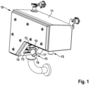
- Fig. 1 shows a perspective view of the device 10 according to the invention.
- the device 10 is designed and set up for the optical inspection of articles in the fish and meat processing industry. For example, when processing fish, it is necessary to check the processing result after processing in order to initiate further post-processing steps if necessary.
- the device 10 shown comprises a housing 11 in which an imager 12 set up for optical scanning of the articles is arranged encapsulated on all sides. In the Fig. 1 only one of the imagers 12 is shown visibly, while a second imager, preferably arranged in the housing 11, is shown in the Fig. 1 is covered by the housing 11.
- the number of imagers 12 arranged in the housing 11 is basically arbitrary, but depends on which areas of the articles in the fish and meat processing industry are to be visually inspected.
- the housing 11 also has a translucent viewing window 13, which is preferably arranged on the article side of the housing 11 or forms a light-permeable recess on this housing side 14.
- a protective element 15 is detachably arranged on the viewing window 13.
- the protective element 15 forms a light-permeable channel 16.
- the protective element 15 with its light-permeable channel 16 forms a free line of sight to an inspection area, which is optically scanned by means of the respective imager for inspecting the articles.
- the protective element 15 serves to protect the viewing window 13 from contamination, for example from blood and/or tissue residues and from liquid deposits on the viewing window 13.
- the light-permeable channel 16 of the protective element 15 is preferably designed without an objective. In other words, in particular no light-refracting optical elements, such as lenses or optical filters, are arranged within the light-permeable channel 16.
- the light-permeable channel 16 is therefore advantageously formed exclusively by a channel wall 17, which on the one hand serves as a shielding element for the viewing window 13 and shields it against the aforementioned contamination along the viewing axis and on the other hand advantageously fulfills the function of a stray light shield. In addition to the protective function against contamination of the viewing window 13, this effectively shields and dampens the incidence of light on the at least one image generator 12 by light rays that do not run essentially parallel to the viewing axis of the image generator 12.
- Fig. 2 shows a side view of the device according to the invention, whereby for reasons of better clarity only the housing side 14 is shown.
- the exemplary in Fig. 2 The device according to the invention shown comprises two of the imagers 12, which are each arranged at an angle to each other, so that they inspect the articles of the fish and meat processing industry from different angles.
- Each of the imagers 12 is assigned one of the transparent viewing windows 13, which as in the Fig. 2 shown, according to an advantageous embodiment of the invention, is designed in two parts.
- Each of the imagers 12 is assigned one of the protective elements 15, which are each detachably arranged on the outside of the housing on the respective viewing window 13.
- the protective element 15 is arranged on the viewing window 13 in such a way that at least one detection area of the imager 12 is enclosed while maintaining a clear view of the articles.
- the detection area of the imager 12 refers to the area within which the imager 12 is able to optically scan the articles.
- a partial area of the viewing window 13 is to be regarded as belonging to the detection area.
- the protective element 15 is now arranged around this partial area in such a way that it is enclosed on all sides by the protective element 15 on the one hand, but on the other hand - with the exception of the previously described shielding function against scattered light - there is no restriction of the imager-side field of view.
- the protective element 15 is arranged centrally on the viewing window 13 with respect to the imager 12.
- the protective element 15 has a protective element base 19. As shown in the Fig. 4 As can be seen, the protective element base 19 comprises a central light passage recess 20. The light passage recess 20 is preferably arranged in alignment with the light-permeable channel 16. The protective element base 19 preferably projects beyond the channel wall 17 of the protective element 15 at least laterally, so that the protective element base 19 forms a contact surface 21 by means of which the protective element base 19 can be arranged flat on the viewing window 13.
- the contact surface 21 is also preferably designed to be flat and, when arranged, lies flush on the outside of the housing against the viewing window 13. This ensures that undesirable penetration of liquids and/or dirt between the contact surface 21 and the viewing window 13 is excluded.
- holding means 22 are provided which are designed to detachably arrange the protective element base 19 on the viewing window 13. As can be seen in the perspective interior view of the device according to the invention with the housing hidden in Fig. 3 As shown, the holding means 22 are arranged on the inside of the housing. Furthermore, the holding means 22 are designed as holding magnets 23 or each comprise these holding magnets 23.
- the protective element base 19 comprises at least partially, i.e. at least in some partial areas, a magnetic and/or magnetizable material.
- the protective element base 19 is, for example, made partially or completely from a ferromagnetic material.
- the protective element base 19 comprises magnets 34 embedded in the contact surface 21 and/or ferromagnetic partial surfaces.
- the polarities of the holding magnets 23 and those of the protective element base 19 are aligned in such a way that they attract each other and the entire protective element 15 is thus held independently on the viewing window 13.
- a further advantage is that the protective element 15 can be positioned in a clearly centered arrangement due to the opposite polarities.
- a particular advantage of the previously described design of the holding means 22 and the protective element base 19 is the particularly easy handling of the device according to the invention.
- the protective element 15 can thus be arranged on the viewing window 13 with a simple movement without complex assembly work.
- the protective element 15 according to the invention can be detached from the viewing window 13 in the same way with a simple movement. This has a particular effect on the high hygiene requirements that regularly exist in the fish and meat processing industry.
- the viewing window 13 can be cleaned particularly easily as a flat component and there is no risk of contamination remaining in hard-to-reach places due to complex external geometries.
- the removed protective element 15 can be cleaned and disinfected separately.
- the protective element base 19 is designed such that it merges without a gap into a channel wall 17 forming the light-permeable channel 16.
- the channel wall 17 and the protective element base 19 form a continuously closed envelope surface that shields the light-permeable channel 16 and the light passage recess 20.
- the channel wall 17 and the protective element base 19 are formed in one piece.
- the channel wall 17 of the protective element 15 is preferably designed as a hollow cylinder. As shown in the drawing, this hollow cylinder-shaped design of the channel wall 17 preferably has a circular cross-sectional area. Alternatively, the cross-sectional area is, for example, elliptical, rectangular or any polygonal shape. In particular, with a non-circular cross-sectional area, an increased or reduced shielding effect against dirt and liquid ingress can be achieved by selecting an appropriate cross-sectional area geometry. For example, when processing articles in the fish and meat processing industry, it is possible to keep certain contaminants that hit the device according to the invention from a preferred direction from impact surfaces formed by the channel wall 17.
- the channel wall 17 of the protective element 15 can be aligned, for example, such that the main axis of the elliptical cross-sectional area is perpendicular or at least substantially perpendicular to the preferred direction from which the greatest proportion of contamination/contamination that may arise during the processing of the items is to be expected.
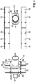
- the present invention is Fig. 4 schematically shown and shows the device according to the invention in plan view looking towards the viewing window 13.
- the viewing window 13 is in the Fig. 4 as well as the housing 11 is not shown.
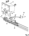
- Fig. 5 shows a perspective view of the arrangement according to the invention for processing and inspecting the opened abdominal cavity 30 of gutted fish 29.
- the arrangement according to the invention comprises a conveyor device 26 which is designed to convey the fish in the longitudinal direction 27 along a processing line 28.
- the processing line 28 is shown in a simplified form in the form of only one tool for keeping the abdominal cavity 30 of the fish open.
- the arrangement further comprises at least one device 10 according to the invention designed for optical inspection of the abdominal cavity 30, which has been described in detail above.
- Fig. 5 As can be seen, the device 10 according to the invention is arranged above the conveyor device 26 and the processing line 28. The fish 29 transported by means of the conveyor device 26 are supported on the back of the conveyor device 26 so that their abdominal cavity 30 is directed upwards. This offers the advantage that liquid spray and/or tissue parts of the fish 29 that arise during the processing of the fish 29 and which can lead to contamination of the viewing window 13 are deflected downwards due to gravity.
- the conveyor device 26 is set up to convey the fish 29 lying with the opened abdominal cavity 30 facing upwards and to arrange the at least one device 10 with the viewing window 13 facing the processing line 28 above the processing line 28.
- At least one of the protective elements 15 is arranged such that the light-permeable channel 16 is at least substantially perpendicular to the longitudinal direction 27.
- one of the protective elements 15, which is arranged upstream with respect to the longitudinal direction 27, is arranged exactly perpendicularly with respect to the longitudinal direction 27.
- the further downstream protective element 15 is arranged inclined with respect to the longitudinal direction 27, thus deviating slightly from the vertical alignment.
- the arrangement according to the invention comprises at least one lighting device 31 designed to illuminate the abdominal cavity 30 of the fish 29.
- Each of the lighting devices 31 is preferably arranged on the inside of the housing on the viewing window 13 and is laterally spaced from the at least one image generator 12.
- Fig. 4 As shown, for example, four of the lighting devices 31 are arranged laterally spaced around the protective element 15. Laterally next to the left in Fig. 4 Two of the illumination devices 31 are arranged in each of the image generators 12 shown.
- the at least one lighting device 31 is advantageously designed as a surface radiator.
- the lighting device 31 comprises LED arrays, for example. Its emitting surface 33 is also preferably arranged at an angle to the viewing window 15, in particular the emitting surface 33 is inclined such that the main light emission direction is aligned at an angle to one of the lines of sight 32 between the respective image generator 12 and the abdominal cavity 30. On the one hand, this increases the illuminance by superimposing the light components of the lighting devices 31. On the other hand, the lighting devices 31 arranged on both sides of the protective element 15 ensure uniform illumination of the abdominal cavity 30 and avoid any shadows caused by the protective element 15 itself.
- the lighting devices 31 shown are each arranged to form an air gap on the viewing window 15. This ventilation of the lighting devices 31 has a positive effect on the dissipation of waste heat and at the same time offers the advantage that possible condensation formation between the viewing window 13 and the radiating surface 33 is avoided.
- the lighting devices 31 are preferably arranged detachably by means of screw connections 25 on the viewing window 13 or on the housing side 14.
Landscapes
- Life Sciences & Earth Sciences (AREA)
- Engineering & Computer Science (AREA)
- Food Science & Technology (AREA)
- Health & Medical Sciences (AREA)
- Chemical & Material Sciences (AREA)
- Physics & Mathematics (AREA)
- General Physics & Mathematics (AREA)
- Analytical Chemistry (AREA)
- Biochemistry (AREA)
- General Health & Medical Sciences (AREA)
- Immunology (AREA)
- Pathology (AREA)
- Biophysics (AREA)
- Computer Vision & Pattern Recognition (AREA)
- Wood Science & Technology (AREA)
- Zoology (AREA)
- Medicinal Chemistry (AREA)
- Investigating Or Analysing Materials By Optical Means (AREA)
- Investigating Materials By The Use Of Optical Means Adapted For Particular Applications (AREA)
- Processing Of Meat And Fish (AREA)
Description
- Die vorliegende Erfindung betrifft eine Vorrichtung, ausgebildet und eingerichtet zur optischen Inspektion von Artikeln der fisch- und fleischverarbeitenden Industrie. Des Weiteren betrifft die Erfindung eine Anordnung zur Bearbeitung und Inspektion der geöffneten Bauchhöhle entweideter Fische, wobei diese eine zum Fördern der Fische in Längsrichtung entlang einer Bearbeitungslinie eingerichtete Fördereinrichtung umfasst.
- Derartige Vorrichtungen kommen bei der industriellen Verarbeitung von Fisch- und Fleischwaren zum Einsatz. Die Be- und Verarbeitung derartiger Artikel erfolgt größtenteils mittels automatisch gesteuerter Werkzeuge. Die Verarbeitungsschritte werden zu Kontroll- und Steuerungszwecken optisch überwacht. Hierzu werden die zu bearbeitenden oder bearbeiteten Artikel mittels optischer Bildgeber abgetastet und die so gewonnenen Bilddaten halb- oder vollautomatisch ausgewertet.
- Die eingangs genannte Anordnung kommt bei der industriellen Fischverarbeitung zum Einsatz. Hierbei werden die Fische einer automatischen Schlachteinrichtung zugeführt, mittels derer u. a. die Bauchhöhle der Fische geöffnet und die Eingeweide aus dieser durch Eingriff entsprechender Werkzeuge automatisch entfernt werden. Um das Ergebnis dieses Entweidevorgangs zu überprüfen, wird die Bauchhöhle der Fische anschließend optisch abgetastet und auf Basis der erhaltenen Bilddaten mittels geeigneter Bildverarbeitungsalgorithmen entsprechenden Prüfungen durchgeführt.
- Bei den bekannten Vorrichtungen und Anordnungen sind die Bildgeber Verunreinigungen ausgesetzt, die während des Verarbeitungsvorgangs entstehenden können. In relativ kurzer Zeit setzen sich beispielsweise Blut- und Gewebsreste, diverse Schmutzpartikel und/oder Flüssigkeitströpfchen an den Objektiven der Bildgeber bzw. in deren Sichtfeld fest. Mit zunehmendem Verunreinigungsgrad wird so nachteiligerweise die freie Sicht des Bildgebers auf die abzutastenden Bereiche der Artikel eingeschränkt, so dass es von Fehlbildauswertungen bis hin zum Totalausfall der optischen Inspektion kommen kann. Der gesamte Produktionsprozess ist in diesem Fall anzuhalten und zunächst eine Reinigung der jeweiligen Komponenten vorzunehmen, so dass es zu unerwünschten Stillstandzeiten und Produktionsunterbrechungen kommt.
- Aus der
WO 2007/090724 A1 ist eine Vorrichtung zur optischen Inspektion von Artikeln bekannt mit einem lösbar angeordneten Schutzelement. - Es ist daher Aufgabe der vorliegenden Erfindung eine Vorrichtung der eingangs genannten Art vorzuschlagen, die eine möglichst zuverlässige optische Inspektion der genannten Artikel gewährleistet und zugleich möglichst einfach, komfortabel und rasch zu reinigen ist. Des Weiteren besteht die Aufgabe darin, eine Anordnung der eingangsgenannten Art vorzuschlagen, mittels derer eine zuverlässige optische Inspektion der geöffneten Bauchhöhle entweideter Fische ermöglicht wird, die zugleich eine rasche und hygienische Reinigung der für die optische Inspektion relevanten Bauteile erlaubt.
- Die Aufgabe wird durch eine Vorrichtung nach Anspruch 1 gelöst. Auf diese Weise ist der Bildgeber einerseits mittels des lichtdurchlässigen Sichtfensters vor unmittelbarer Einwirkung durch Verunreinigung geschützt. Andererseits wird mittels des Schutzelements das Sichtfenster, insbesondere im Erfassungsbereich des Bildgebers, abgeschirmt und der Sicht- bzw. Erfassungsbereich des Bildgebers weitestgehend frei von Verunreinigung gehalten bzw. ein Anhaften von Verunreinigung an dem Sichtfenster stark reduziert.
- Ein weiterer Vorteil besteht darin, dass das Schutzelement gehäuseaußenseitig an dem Sichtfenster lösbar angeordnet ist. Zu Reinigungszwecken kann das Schutzelement daher ohne großen Aufwand rasch von dem Sichtfenster gelöst werden und das Sichtfenster und das Schutzelement gereinigt werden. Durch die Abnehmbarkeit des Schutzelements lässt sich dieses insbesondere separat reinigen und - sofern erforderlich - desinfizieren.
- Die allseitig gekapselte Anordnung des Bildgebers in dem Gehäuse vereinfacht die Reinigung der erfindungsgemäßen Vorrichtung wesentlich, da der Bildgeber geschützt, insbesondere spritz- und strahlwassergeschützt, angeordnet ist und so auf empfindliche Komponenten des Bildgebers beim Reinigungsvorgang nicht gesondert Rücksicht genommen werden muss.
- Unter Hygienegesichtspunkten, an die im Bereich der fisch- und fleischverarbeitenden Industrie regelmäßig besonders hohe Anforderungen gestellt werden, wirkt sich die möglichst einfach gehaltene Struktur der erfindungsgemäßen Vorrichtung besonders positiv aus. Auf diese Weise wird ein andernfalls mögliches Ablagern von Verunreinigungen an unzugänglichen Bereichen weitestgehend ausgeschlossen. Das Gehäuse sowie das Sichtfenster weisen möglichst ebene bzw. plane Oberflächen auf, die besonders leicht und komfortabel zu reinigen sind und im Wesentlichen keine vorsprungs- und/oder hinterschneidungsbehaftete Außengeometrie aufweisen, die ein Anhaften von Verunreinigungen begünstigen und den Reinigungsvorgang insgesamt verkomplizieren würden.
- Erfindungsgemäß ist vorgesehen, dass das Schutzelement an dem Sichtfenster angeordnet ist und zumindest einen Erfassungsbereich des Bildgebers unter Beibehaltung freier Sicht auf die Artikel umschließt. Vorteilhafterweise wird so das Sichtfeld des Bildgebers durch das Schutzelement nicht oder nur unwesentlich eingeschränkt. Zugleich ist der Erfassungsbereich des Bildgebers wirksam gegen das Eintreten von beim Verarbeitungsprozess entstehenden Verunreinigungen abgeschirmt. So wird das Auftreffen derartiger Verunreinigungen auf das Sichtfester im relevanten Erfassungsbereich zuverlässig vermieden. Vorzugsweise wird der Erfassungsbereich des Bildgebers von dem Schutzelement allseitig umschlossen. Weiter bevorzugt ist das Schutzelement bezüglich des Bildgebers mittig zentriert angeordnet, so dass die Schirm- und Schutzwirkung des Schutzelements für jeden Teilbereich des Erfassungsbereichs in gleicher Form vorhanden ist. Das Schutzelement ist also vorzugsweise derart angeordnet, dass eine gedachte Mittelachse des Schutzelements mit der Sichtachse des Bildgebers deckungsgleich zusammenfällt.
- Erfindungsgemäß weist das Schutzelement eine Schutzelementbasis mit einer zentralen Lichtdurchgangsausnehmung auf und gehäuseseitig sind Haltemittel vorhanden, die jeweils eingerichtet sind, die Schutzelementbasis an dem Sichtfenster lösbar anzuordnen. Die Schutzelementbasis ist als Stütz- und Anlageelement ausgebildet und ist zur Anlage an dem Sichtfenster eingerichtet. Vorzugsweise ist die Schutzelementbasis so ausgebildet, dass diese die Kanalwandung des lichtdurchgängigen Kanals seitlich überragt. Die Schutzelementbasis ist so als Stand- bzw. Anlageflächenerweiterung ausgebildet, mittels derer die Schutzelementbasis an dem Sichtfenster flächig anordenbar eingerichtet ist.
- Vorzugsweise ist eine Anlagefläche der Schutzelementbasis plan ausgeführt und liegt im angeordneten Zustand gehäuseaußenseitig an dem Sichtfenster bündig an. Dies bietet den Vorteil, ein unerwünschtes Eindringen von Flüssigkeiten und/oder Verschmutzungen zwischen der Anlagefläche und dem Sichtfenster wirksam zu verhindern.
- Erfindungsgemäß sind gehäuseseitig Haltemittel angeordnet, die zur lösbaren Anordnung der Schutzelementbasis an dem Sichtfenster eingerichtet sind. Erfindungsgemäß sind die Haltemittel gehäuseinnenseitig angeordnet. Die Haltemittel sind als Haltemagnete ausgebildet oder umfassen solche. Die Schutzelementbasis weist ebenfalls Haltemagnete auf und/oder ist aus einem magnetischen bzw. magnetisierbaren Werkstoff gefertigt.
- Gemäß einer zweckmäßigen Ausgestaltung der Erfindung ist die Schutzelementbasis spaltfrei in die den lichtdurchgängigen Kanal bildende Kanalwandung übergehend eingerichtet. Vorteilhafterweise bilden so die Kanalwandung und die Schutzelementbasis eine durchgängig geschlossene Hüllfläche. Auf diese Weise wird der zu schützende Bereich des Sichtfensters im Erfassungsbereich des Bildsensors optimal vor Verunreinigungen abgeschirmt. Weiter bevorzugt sind die Kanalwandung und die Schutzelementbasis einstückig ausgebildet.
- Eine vorteilhafte Weiterbildung der Erfindung sieht vor, dass die Kanalwandung des Schutzelements hohlzylinderförmig mit einer kreisrunden, elliptischen, rechteckigen oder polygonförmigen Querschnittsfläche ausgebildet ist. Durch die Wahl der Querschnittsflächengeometrie kann die Schirmwirkung optimal an den jeweiligen Einsatzzweck angepasst werden. So ist es beispielsweise möglich, bei der Verarbeitung der Artikel der fisch- und fleischverarbeitenden Industrie, bestimmte aus einer Vorzugsrichtung auf die erfindungsgemäße Vorrichtung treffende, Verunreinigungen an den durch die Kanalwandung gebildeten Prallflächen abzuhalten. Je nach Einsatzzweck und der sich daraus ergebenden Hauptrichtung, aus der mit einem Anfall von Verunreinigungen zu rechnen ist, können die von den Kanalwandungen gebildeten Prallflächen entsprechend angepasst werden.
- Gemäß einer weiteren vorteilhaften Ausbildung ist die Kanalwandung des Schutzelements als Hohlkegel- oder Hohlpyramidenstumpf ausgebildet. Anders ausgedrückt ist das Schutzelement bzw. die Kanalwandung des Schutzelements trichterartig ausgebildet. Vorzugsweise ist die Seite mit geringerem Querschnitt zu dem Sichtfenster gerichtet, so dass sich der Kanalquerschnitt in Richtung der zu inspizierenden Artikel weitet. Hierdurch wird bei möglichst geringer Baugröße des Schutzelements eine Beeinflussung des optischen Strahlengangs durch das Schutzelement selbst auf ein Minimum reduziert, so dass die Artikel im Erfassungsbereich des Bildgebers ungestört aufgenommen werden können. Die Kanalwandungen sind auf diese Weise optimal an die sich mit zunehmendem Abstand vom Bildgeber gegebene Aufweitung des optischen Strahlengangs angepasst.
- Die Aufgabe wird auch durch die eingangs genannte Anordnung gelöst, die sich dadurch auszeichnet, dass diese mindestens eine zur optischen Inspektion der Bauchhöhle eingerichtete Vorrichtung mit zuvor beschriebenen Merkmalen umfasst. Die sich aus der erfindungsgemäßen Vorrichtung ergebenden und zuvor dargelegten Vorteile gelten in gleicher Weise für die erfindungsgemäße Anordnung. Zur Vermeidung von Wiederholung wird daher hierauf verwiesen.
- Eine vorteilhafte Weiterbildung zeichnet sich dadurch aus, dass die Fördereinrichtung eingerichtet ist, die Fische mit der geöffneten Bauchhöhle nach oben weisend liegend zu fördern, wobei die mindestens eine Vorrichtung mit dem Sichtfenster zu der Bearbeitungslinie zeigend oberhalb der Bearbeitungslinie angeordnet ist. Dies bietet den Vorteil, dass beim Verarbeitungsprozess entstehende Verunreinigungen der Schwerkraft folgend nach unten abgelenkt werden und bereits hierdurch der Anteil an in den Bereich der erfindungsgemäßen Vorrichtung vordringender Verunreinigung erheblich reduziert ist.
- Gemäß einer weiteren Ausbildung ist wenigstens eines der Schutzelemente derart angeordnet, dass der lichtdurchgängige Kanal zumindest im Wesentlichen senkrecht zu der Längsrichtung weisend ausgerichtet ist. Die bei der Verarbeitung der Fische entstehenden festen und flüssigen Bestandteile verteilen sich in alle Raumrichtungen nach dem Zufallsprinzip. Nach oben gerichtete Bewegungskomponenten der Bestandteile werden durch Schwerkrafteinwirkung "gebremst", so dass die Bestandteile sich im Wesentlichen auf mehr oder weniger gekrümmten Bahnen bewegen. Die Wahrscheinlichkeit, dass sich Bestandteile in einer im Wesentlichen senkrecht zum Erdboden gerichteten Bahn entgegen der Schwerkraft bewegen ist folglich deutlich geringer gegenüber anderen Bahnrichtungen. Durch die Ausrichtung des lichtdurchgängigen Kanals senkrecht oder im Wesentlichen senkrecht zu der Längsrichtung ist dieser so ausgerichtet, dass die freie Öffnung des Kanalschenkels in die Richtung zeigt, aus der der geringste Anteil der genannten Bestandteile zu erwarten ist, die zu einer etwaigen Verunreinigung des Sichtfensters führen könnten.
- Bevorzugt umfasst die erfindungsgemäße Anordnung mindestens eine zum Beleuchten der Bauchhöhle der Fische eingerichtete Beleuchtungseinrichtung, wobei die Beleuchtungseinrichtung gehäuseinnenseitig an dem Sichtfenster von dem mindestens einen Bildgeber seitlich beabstandet angeordnet ist.
- Gemäß einer vorteilhaften Weiterbildung der Erfindung ist vorgesehen, dass die mindestens eine Beleuchtungseinrichtung als Flächenstrahler ausgebildet ist, deren Abstrahlfläche gegenüber dem Sichtfenster geneigt angeordnet ist. Auf diese Weise wird eine möglichst gleichmäßige Ausleuchtung der Bauchhöhle gewährleistet. Zudem wird die Beleuchtungsstärke durch die Überlagerung mehrerer Lichtquellen erhöht.
- Eine zweckmäßige Ausbildung zeichnet sich dadurch, dass die Abstrahlfläche so geneigt ist, dass die Hauptlichtabstrahlrichtung jeweils zu einer Sichtlinie zwischen Bildgeber und Bauchhöhle hingeneigt ausgerichtet ist. Durch das Schutzelement entstehende Schattenbildung wird auf diese Weise durch beidseitiges Ausleuchten ausgeschlossen und eine möglichst homogene Ausleuchtung der Bauchhöhle erzielt.
- Bevorzugt ist die mindestens eine Beleuchtungseinrichtung unter Bildung eines Luftspaltes an dem Sichtfenster angeordnet. Auf diese Weise ist eine optimale Kühlung der Beleuchtungseinrichtungen und die Einhaltung der maximal zulässigen Betriebstemperatur gewährleistet. Zudem sind die Beleuchtungseinrichtungen auf diese Weise hinterlüftet eingerichtet, was einer andernfalls möglichen Kondensatbildung zwischen den Abstrahlflächen der Beleuchtungseinrichtungen und dem Sichtfenster entgegenwirkt.
- Weitere bevorzugte und/oder zweckmäßige Merkmale und Ausgestaltungen der Erfindung ergeben sich aus den Unteransprüchen und der Beschreibung. Besonders bevorzugte Ausführungsformen werden anhand der beigefügten Zeichnung näher erläutert. In der Zeichnung zeigt:
- Fig. 1
- eine perspektivische Ansicht der erfindungsgemäßen Vorrichtung,
- Fig. 2
- eine Seitenansicht der erfindungsgemäßen Vorrichtung ohne Gehäuse,
- Fig. 3
- eine perspektivische Innenansicht der erfindungsgemäßen Vorrichtung mit ausgeblendetem Gehäuse
- Fig. 4
- eine schematische Darstellung der erfindungsgemäßen Vorrichtung in Draufsicht mit außenseitigem Blick auf das Sichtfenster und
- Fig. 5
- eine perspektivische Ansicht der erfindungsgemäßen Anordnung.
-
Fig. 1 zeigt eine perspektivische Ansicht der erfindungsgemäßen Vorrichtung 10. Die Vorrichtung 10 ist zur optischen Inspektion von Artikeln der fisch- und fleischverarbeitenden Industrie ausgebildet und eingerichtet. So ist es beispielsweise erforderlich, bei der Verarbeitung von Fischen nach erfolgter Bearbeitung das Bearbeitungsergebnis zu überprüfen, um erforderlichenfalls weitere Nachbearbeitungsschritte einzuleiten. Die gezeigte Vorrichtung 10 umfasst ein Gehäuse 11, in dem ein zum optischen Abtasten der Artikel eingerichteter Bildgeber 12 allseitig gekapselt angeordnet ist. In derFig. 1 ist nur einer der Bildgeber 12 sichtbar dargestellt, während ein, vorzugsweise in dem Gehäuse 11 angeordneter, zweiter Bildgeber in der Darstellung derFig. 1 durch das Gehäuse 11 verdeckt wird. Die Zahl der in dem Gehäuse 11 angeordneten Bildgeber 12 ist grundsätzlich beliebig, richtet sich jedoch danach, welche Bereiche der Artikel der fisch- und fleischverarbeitenden Industrie optisch inspiziert werden sollen. Das Gehäuse 11 weist weiter ein lichtdurchlässiges Sichtfenster 13 auf, das vorzugsweise artikelseitig an dem Gehäuse 11 angeordnet ist bzw. an dieser Gehäuseseite 14 eine lichtdurchgängige Ausnehmung bildet. - Gehäuseaußenseitig ist ein Schutzelement 15 an dem Sichtfenster 13 lösbar angeordnet. Das Schutzelement 15 bildet einen lichtdurchgängigen Kanal 16. Ausgehend von dem jeweiligen Bildgeber 12 bildet das Schutzelement 15 mit seinem lichtdurchgängigen Kanal 16 eine freie Sichtachse auf ein Inspektionsbereich, der mittels des jeweiligen Bildgebers zur Inspektion der Artikel optisch abgetastet wird.
- Das Schutzelement 15 dient dem Schutz des Sichtfensters 13 vor Verunreinigung, beispielsweise durch Blut- und/oder Gewebsreste sowie vor Flüssigkeitsniederschlag auf dem Sichtfenster 13. Vorzugsweise ist der lichtdurchgängige Kanal 16 des Schutzelements 15 objektivfrei ausgebildet. Mit anderen Worten sind innerhalb des lichtdurchgängigen Kanals 16 insbesondere keine lichtbrechenden optischen Elemente angeordnet, wie beispielsweise Linsen oder optische Filter. Der lichtdurchgängige Kanal 16 wird also vorteilhafterweise ausschließlich durch eine Kanalwandung 17 gebildet, die einerseits als Abschirmelement für das Sichtfenster 13 dienst und dieses gegen die genannten Verunreinigungen entlang der Sichtachse abschirmt und andererseits vorteilhafterweise die Funktion einer Streulichtblende erfüllt. Durch diese wird zusätzlich zu der Schutzfunktion gegen Verunreinigungen des Sichtfensters 13 der Einfall von Licht auf den mindestens einen Bildgeber 12 durch Lichtstrahlen, die nicht im Wesentlichen parallel zu der Sichtachse des Bildgebers 12 verlaufen, wirksam abgeschirmt und gedämpft.
-
Fig. 2 zeigt eine Seitenansicht der erfindungsgemäßen Vorrichtung, wobei aus Gründen der besseren Übersichtlichkeit nur die Gehäuseseite 14 gezeigt ist. Die beispielhaft inFig. 2 gezeigte erfindungsgemäße Vorrichtung umfasst zwei der Bildgeber 12, die jeweils geneigt zueinander angeordnet sind, so dass diese die Artikel der fisch- und fleischverarbeitenden Industrie jeweils unter verschiedenen Blickwinkeln inspizieren. Jedem der Bildgeber 12 ist jeweils eines der lichtdurchlässigen Sichtfenster 13 zugeordnet, das wie in derFig. 2 gezeigt, gemäß einer vorteilhaften Ausbildung der Erfindung zweiteilig ausgebildet ist. Jedem der Bildgeber 12 ist jeweils eines der Schutzelemente 15 zugeordnet, die jeweils gehäuseaußenseitig an dem jeweiligen Sichtfenster 13 lösbar angeordnet sind. - Das Schutzelement 15 ist derart an dem Sichtfenster 13 angeordnet, dass zumindest ein Erfassungsbereich des Bildgebers 12 unter Beibehaltung freier Sicht auf die Artikel umschlossen wird. Der Erfassungsbereich des Bildgebers 12 bezeichnet denjenigen Bereich, innerhalb dessen der Bildgeber 12 in der Lage ist, die Artikel optisch abzutasten. Ausgehend von dem Bildgeber 12 ist so ein Teilbereich des Sichtfensters 13 als zum Erfassungsbereich zugehörigen anzusehen. Das Schutzelement 15 ist nun so um diesen Teilbereich angeordnet, dass dieser von dem Schutzelement 15 einerseits allseitig umschlossen wird, es andererseits jedoch - mit Ausnahme der zuvor beschriebenen Abschirmfunktion gegen Streulicht - zu keiner Einschränkung des bildgeberseitigen Sichtfeldes führt. Vorzugsweise ist das Schutzelement 15 bezüglich des Bildgebers 12 mittig zentriert an dem Sichtfenster 13 angeordnet.
- Das Schutzelement 15 weist eine Schutzelementbasis 19 auf. Wie in der
Fig. 4 ersichtlich, umfasst die Schutzelementbasis 19 eine zentrale Lichtdurchgangsausnehmung 20. Vorzugsweise ist die Lichtdurchgangsausnehmung 20 fluchtend zu dem lichtdurchgängigen Kanal 16 angeordnet. Die Schutzelementbasis 19 überragt vorzugsweise die Kanalwandung 17 des Schutzelements 15 zumindest seitlich, so dass die Schutzelementbasis 19 eine Anlagefläche 21 bildet, mittels derer die Schutzelementbasis 19 an dem Sichtfenster 13 flächig anordenbar eingerichtet ist. - Weiter bevorzugt ist die Anlagefläche 21 plan ausgeführt und liegt im angeordneten Zustand gehäuseaußenseitig an dem Sichtfenster 13 bündig an. Auf diese Weise wird erreicht, dass ein unerwünschtes Eindringen von Flüssigkeiten und/oder Verschmutzungen zwischen der Anlagefläche 21 und dem Sichtfenster 13 ausgeschlossen ist. Gehäuseseitig sind Haltemittel 22 vorhanden, die eingerichtet sind, die Schutzelementbasis 19 an dem Sichtfenster 13 lösbar anzuordnen. Wie in der perspektivischen Innenansicht der erfindungsgemäßen Vorrichtung mit ausgeblendetem Gehäuse in
Fig. 3 gezeigt, sind die Haltemittel 22 gehäuseinnenseitig angeordnet. Weiter sind die Haltemittel 22 als Haltemagnete 23 ausgebildet bzw. umfassen jeweils diese Haltemagnete 23. - Die Schutzelementbasis 19 umfasst zumindest teilweise, das heißt zumindest in einigen Teilbereichen, einen magnetischen und/oder magnetisierbaren Werkstoff. Die Schutzelementbasis 19 ist beispielsweise zum Teil oder vollständig aus einem ferromagnetischen Werkstoff hergestellt. Alternativ umfasst die Schutzelementbasis 19 in die Anlagefläche 21 eingelassene Magnete 34 und/oder ferromagnetische Teilflächen. In jedem Fall sind die Polaritäten der Haltemagnete 23 sowie derjenigen der Schutzelementbasis 19 derart ausgerichtet, dass diese sich gegenseitig anziehen und so das gesamte Schutzelement 15 selbstständig an dem Sichtfenster 13 gehalten wird. Ein weiterer Vorteil besteht darin, dass das Schutzelement 15 durch die entgegengesetzten Polaritäten in eine eindeutig zentrierte Anordnung positionierbar ist.
- Ein besonderer Vorteil in der zuvor beschriebenen Ausbildung der Haltemittel 22 sowie der Schutzelementbasis 19 besteht in der besonders einfachen Handhabbarkeit der erfindungsgemäßen Vorrichtung. So kann das Schutzelement 15 ohne aufwendige Montagearbeiten, an dem Sichtfenster 13 mit einem einfachen Handgriff angeordnet werden. Zu Reinigungs- und Wartungszwecken lässt sich das erfindungsgemäße Schutzelement 15 in gleicher Weise mit einem einfachen Handgriff von dem Sichtfenster 13 ablösen. Diese wirkt sich insbesondere auf die im Bereich der fisch- und fleischverarbeitenden Industrie regelmäßig vorhandenen hohen Hygieneanforderung aus. Nach Abnahme des Schutzelements 15 von dem Sichtfenster 13 kann das Sichtfenster 13 als planes Bauteil besonders leicht gereinigt werden und es besteht nicht die Gefahr, dass Verunreinigungen aufgrund komplexer Außengeometrien an schlecht zugänglichen Stellen zurückbleiben. Zudem lässt sich das abgenommene Schutzelement 15 separat reinigen und desinfizieren.
- Vorteilhafterweise ist die Schutzelementbasis 19 so eingerichtet, dass diese spaltfrei in eine den lichtdurchgängigen Kanal 16 bildende Kanalwandung 17 übergeht. Mit anderen Worten bilden die Kanalwandung 17 und die Schutzelementbasis 19 eine durchgängig geschlossene Hüllfläche, die den lichtdurchgängigen Kanal 16 sowie die Lichtdurchgangsausnehmung 20 abschirmen. Weiter bevorzugt sind die Kanalwandung 17 und die Schutzelementbasis 19 einstückig ausgebildet.
- Vorzugsweise ist die Kanalwandung 17 des Schutzelements 15 hohlzylinderförmig ausgebildet. Wie in der Zeichnung gezeigt, weist diese hohlzylinderförmige Ausbildung der Kanalwandung 17 vorzugsweise eine kreisrunde Querschnittsfläche auf. Alternativ ist die Querschnittsfläche beispielsweise elliptisch, rechteckig oder beliebig polygonförmig eingerichtet. Insbesondere bei nicht kreisrunder Querschnittsfläche kann durch Wahl einer entsprechenden Querschnittsflächengeometrie eine verstärkte oder verminderte Schirmwirkung gegen Schmutz und Flüssigkeitseintrag erzielt werden. So ist beispielsweise möglich, bei der Verarbeitung der Artikel der fisch- und fleischverarbeitenden Industrie bestimmte aus einer Vorzugsrichtung auf die erfindungsgemäße Vorrichtung treffende Verunreinigungen an durch die Kanalwandung 17 gebildeten Prallflächen abzuhalten.
- Beim Einsatz einer elliptischen Querschnittsfläche lässt sich die Kanalwandung 17 des Schutzelements 15 beispielsweise derart ausrichten, dass die Hauptachse der elliptischen Querschnittsfläche senkrecht oder zumindest im Wesentlichen senkrecht zu der Vorzugsrichtung ausgebildet ist, aus der erwartungsgemäß mit dem größten Anteil an bei der Verarbeitung der Artikel anfallenden Verschmutzung/Verunreinigung zu rechnen ist.
- Ergänzend ist die vorliegende Erfindung in
Fig. 4 schematisch dargestellt und zeigt die erfindungsgemäße Vorrichtung in Draufsicht mit Blickrichtung auf das Sichtfenster 13. Das Sichtfenster 13 ist in derFig. 4 ebenso wie das Gehäuse 11 nicht gezeigt. -
Fig. 5 zeigt eine perspektivische Ansicht der erfindungsgemäßen Anordnung zur Bearbeitung und Inspektion der geöffneten Bauchhöhle 30 entweideter Fische 29. Die erfindungsgemäße Anordnung umfasst eine Fördereinrichtung 26, die zum Fördern der Fische in Längsrichtung 27 entlang einer Bearbeitungslinie 28 eingerichtet ist. Aus Gründen der besseren Übersichtlichkeit ist die Bearbeitungslinie 28 vereinfacht in Form nur eines Werkzeuges zum Offenhalten der Bauchhöhle 30 der Fische dargestellt. - Die Anordnung umfasst weiter mindestens eine zur optischen Inspektion der Bauchhöhle 30 eingerichtete erfindungsgemäße Vorrichtung 10, die zuvor im Detail beschrieben worden ist. Wie der
Fig. 5 zu entnehmen ist, ist die erfindungsgemäße Vorrichtung 10 oberhalb der Fördereinrichtung 26 sowie der Bearbeitungslinie 28 angeordnet. Die mittels der Fördereinrichtung 26 transportierten Fische 29 sind rückenseitig auf der Fördereinrichtung 26 gelagert, so dass deren Bauchhöhle 30 nach oben weisend gerichtet ist. Dies bietet den Vorteil, dass bei der Verarbeitung der Fische 29 entstehender Flüssigkeitssprühnebel und/oder Gewebsteile des Fisches 29, die zu einer Verunreinigung des Sichtfensters 13 führen können, schwerkraftbedingt nach unten abgelenkt werden. - Diejenigen Flüssigkeits- oder Gewebsanteile die in die Nähe der erfindungsgemäßen Vorrichtung 10 gelangen, werden wie zuvor beschrieben durch das erfindungsgemäße Schutzelement 15 an einem Auftreffen auf dem Sichtfenster 13 im Bereich des jeweiligen Bildgebers 12 weitestgehend verhindert. Es ist daher besonders vorteilhaft, dass die Fördereinrichtung 26 eingerichtet ist, die Fische 29 mit der geöffneten Bauchhöhle 30 nach oben weisend liegend zu fördern und die mindestens eine Vorrichtung 10 mit dem Sichtfenster 13 zur Bearbeitungslinie 28 zeigend oberhalb der Bearbeitungslinie 28 anzuordnen.
- Vorzugsweise ist zumindest eines der Schutzelemente 15 derart angeordnet, dass der lichtdurchgängige Kanal 16 zumindest im Wesentlichen senkrecht zu der Längsrichtung 27 ausgerichtet ist. Wie in
Fig. 5 gezeigt, ist eines der Schutzelemente 15, das bezüglich der Längsrichtung 27 vorgeordnet ist, exakt senkrecht gegenüber der Längsrichtung 27 angeordnet. Das weitere nachgeordnete der Schutzelemente 15 ist gegenüber der Längsrichtung 27 geneigt angeordnet, weicht also etwas von der senkrechten Ausrichtung ab. - Wie in
Fig. 2 ,3 und4 gezeigt, umfasst die erfindungsgemäße Anordnung mindestens eine zum Beleuchten der Bauchhöhle 30 der Fische 29 eingerichtete Beleuchtungseinrichtung 31. Jede der Beleuchtungseinrichtungen 31 ist vorzugsweise gehäuseinnenseitig an dem Sichtfenster 13 angeordnet und jeweils von dem mindestens einen Bildgeber 12 seitlich beabstandet. Wie inFig. 4 gezeigt, sind beispielsweise um das Schutzelement 15 vier der Beleuchtungseinrichtungen 31 seitlich beabstandet angeordnet. Seitlich neben den links inFig. 4 gezeigten Bildgeber 12 sind jeweils zwei der Beleuchtungseinrichtungen 31 angeordnet. - Vorteilhafterweise ist die mindestens eine Beleuchtungseinrichtung 31 als Flächenstrahler ausgebildet. Die Beleuchtungseinrichtung 31 umfasst hierzu beispielsweise LED-Arrays. Weiter bevorzugt ist deren Abstrahlfläche 33 gegenüber dem Sichtfenster 15 geneigt angeordnet, insbesondere ist die Abstrahlfläche 33 so geneigt, dass die Hauptlichtabstrahlrichtung jeweils zu einer der Sichtlinien 32 zwischen dem jeweiligen der Bildgeber 12 und der Bauchhöhle 30 hingeneigt ausgerichtet ist. Hierdurch wird einerseits die Beleuchtungsstärke durch Überlagerung der Lichtanteile der Beleuchtungseinrichtungen 31 vergrößert. Anderseits wird durch die beidseits des Schutzelements 15 angeordneten Beleuchtungseinrichtungen 31 eine gleichmäßige Ausleuchtung der Bauchhöhle 30 gewährleistet und etwaige Verschattungen durch das Schutzelement 15 selbst vermieden.
- Die gezeigten Beleuchtungseinrichtungen 31 sind jeweils unter Bildung eines Luftspaltes an dem Sichtfenster 15 angeordnet ist. Diese Hinterlüftung der Beleuchtungseinrichtungen 31 wirkt sich positiv auf Abfuhr entstehender Abwärme aus und bietet zugleich den Vorteil, dass mögliche Kondensatbildung zwischen dem Sichtfenster 13 und der Abstrahlfläche 33 vermieden wird.
- Die Beleuchtungseinrichtungen 31 sind vorzugsweise mittels Schraubverbindungen 25 an dem Sichtfenster 13 bzw. an der Gehäuseseite 14 lösbar angeordnet.
Claims (12)
- Vorrichtung (10), ausgebildet und eingerichtet zur optischen Inspektion von Artikeln der fisch- und fleischverarbeitenden Industrie, umfassendmindestens einen in einem Gehäuse (11) allseitig gekapselt angeordneten und zum optischen Abtasten der Artikel eingerichteten Bildgeber (12), wobeidas Gehäuse (11) ein lichtdurchlässiges Sichtfenster (13) aufweist undgehäuseaußenseitig ein einen lichtdurchgängigen Kanal (16) bildendes Schutzelement (15) zum Schutz des Sichtfensters (13) vor Verunreinigen lösbar angeordnet ist und, dass das Schutzelement (15) an dem Sichtfenster (13) angeordnet ist und zumindest einen Erfassungsbereich des Bildgebers (12) unter Beibehaltung freier Sicht auf die Artikel umschließt, wobeidas Schutzelement (15) eine Schutzelementbasis (19) mit einer zentralen Lichtdurchgangsausnehmung (20) aufweist und gehäuseseitig Haltemittel (22) vorhanden sind, die jeweils eingerichtet sind, die Schutzelementbasis (19) an dem Sichtfenster (13) lösbar anzuordnen, und wobeidie Haltemittel (22) gehäuseinnenseitig angeordnet und als Haltemagneten (23) ausgebildet sind und die Schutzelementbasis (19) zumindest teileweise einen magnetischen und/oder magnetisierbaren Werkstoff umfasst.
- Vorrichtung nach Anspruch 1, dadurch gekennzeichnet, dass die Schutzelementbasis (19) spaltfrei in eine den lichtdurchgängigen Kanal (16) bildende Kanalwandung (17) übergehend eingerichtet ist.
- Vorrichtung nach Anspruch 2, dadurch gekennzeichnet, dass die Kanalwandung (17) und die Schutzelementbasis (19) einstückig ausgebildet ist.
- Vorrichtung nach einem der Ansprüche 2 oder 3, dadurch gekennzeichnet, dass die Kanalwandung (17) des Schutzelements (15) hohlzylinderförmig mit einer kreisrunden, elliptischen, rechteckigen oder polygonförmigen Querschnittsfläche ausgebildet ist.
- Vorrichtung nach einem der Ansprüche 2 oder 3, dadurch gekennzeichnet, dass die Kanalwandung (17) des Schutzelements (15) als Hohlkegel- oder Hohlpyramidenstumpf ausgebildet ist.
- Anordnung zur Bearbeitung und Inspektion der geöffneten Bauchhöhle (30) entweideter Fische (29), umfassendeine zum Fördern der Fische (29) in Längsrichtung (27) entlang einer Bearbeitungslinie (28) eingerichtete Fördereinrichtung (26),dadurch gekennzeichnet,dass die Anordnung mindestens eine zur optischen Inspektion der Bauchhöhle (30) eingerichtete Vorrichtung (10) nach einem der Ansprüche 1 bis 5 umfasst.
- Anordnung nach Anspruch 6, dadurch gekennzeichnet, dass die Fördereinrichtung (26) eingerichtet ist, die Fische (29) mit der geöffneten Bauchhöhle (30) nach oben weisend liegend zu fördern, wobei die mindestens eine Vorrichtung (10) mit dem Sichtfenster (13) zu der Bearbeitungslinie (28) zeigend oberhalb der Bearbeitungslinie (28) angeordnet ist.
- Anordnung nach Anspruch 7, dadurch gekennzeichnet, dass wenigstens eines der Schutzelemente (15) derart angeordnet ist, dass der lichtdurchgängige Kanal (16) zumindest im Wesentlichen senkrecht zu der Längsrichtung (27) weisend ausgerichtet ist.
- Anordnung nach einem der Ansprüche 6 bis 8weiter umfassend mindestens eine zum Beleuchten der Bauchhöhle (30) der Fische (29) eingerichtete Beleuchtungseinrichtung (31), wobei die Beleuchtungseinrichtung (31) gehäuseinnenseitig an dem Sichtfenster (13) von dem mindestens einen Bildgeber (12) seitlich beabstandet angeordnet ist.
- Anordnung nach einem der Ansprüche 6 bis 9, dadurch gekennzeichnet, dass die mindestens eine Beleuchtungseinrichtung (31) als Flächenstrahler ausgebildet ist, deren Abstrahlfläche (33) gegenüber dem Sichtfenster (13) geneigt angeordnet ist.
- Anordnung nach Anspruch 10, dadurch gekennzeichnet, dass die Abstrahlfläche (33) so geneigt ist, dass die Hauptlichtabstrahlrichtung jeweils zu einer Sichtlinie (32) zwischen Bildgeber (12) und Bauchhöhle (30) hingeneigt ausgerichtet ist.
- Anordnung nach einem der Ansprüche 9 bis 11, dadurch gekennzeichnet, dass die mindestens eine Beleuchtungseinrichtung (31) unter Bildung eines Luftspaltes an dem Sichtfenster (13) angeordnet ist.
Applications Claiming Priority (2)
| Application Number | Priority Date | Filing Date | Title |
|---|---|---|---|
| DE102018101835.5A DE102018101835A1 (de) | 2018-01-26 | 2018-01-26 | Vorrichtung und Anordnung zur optischen Inspektion von Artikeln der fisch- und fleischverarbeitenden Industrie |
| PCT/EP2019/051647 WO2019145367A1 (de) | 2018-01-26 | 2019-01-23 | Vorrichtung und anordnung zur optischen inspektion von artikeln der fisch- und fleischverarbeitenden industrie |
Publications (2)
| Publication Number | Publication Date |
|---|---|
| EP3742900A1 EP3742900A1 (de) | 2020-12-02 |
| EP3742900B1 true EP3742900B1 (de) | 2024-10-23 |
Family
ID=65278325
Family Applications (1)
| Application Number | Title | Priority Date | Filing Date |
|---|---|---|---|
| EP19703020.8A Active EP3742900B1 (de) | 2018-01-26 | 2019-01-23 | Vorrichtung und anordnung zur optischen inspektion von artikeln der fisch- und fleischverarbeitenden industrie |
Country Status (11)
| Country | Link |
|---|---|
| US (1) | US11930829B2 (de) |
| EP (1) | EP3742900B1 (de) |
| CN (1) | CN111655037B (de) |
| AU (1) | AU2019211003B2 (de) |
| CA (1) | CA3088592C (de) |
| CL (1) | CL2020001957A1 (de) |
| DE (1) | DE102018101835A1 (de) |
| DK (1) | DK181141B1 (de) |
| ES (1) | ES2996913T3 (de) |
| PL (1) | PL3742900T3 (de) |
| WO (1) | WO2019145367A1 (de) |
Families Citing this family (1)
| Publication number | Priority date | Publication date | Assignee | Title |
|---|---|---|---|---|
| US11940435B2 (en) * | 2021-08-10 | 2024-03-26 | Jiangsu University | Method for identifying raw meat and high-quality fake meat based on gradual linear array change of component |
Citations (1)
| Publication number | Priority date | Publication date | Assignee | Title |
|---|---|---|---|---|
| WO2007090724A1 (de) * | 2006-02-09 | 2007-08-16 | Voith Patent Gmbh | Überwachungseinrichtung |
Family Cites Families (14)
| Publication number | Priority date | Publication date | Assignee | Title |
|---|---|---|---|---|
| DK19992A (da) | 1992-02-17 | 1993-08-18 | Reson System As | System og fremgangsmaade til maaling og/eller identifikation af objekter |
| PL354491A1 (en) * | 1999-07-28 | 2004-01-26 | Marine Harvest Norvay Sa | Method and apparatus for determining quality properties of fish |
| TWM264770U (en) * | 2004-09-07 | 2005-05-11 | Hau-Min Gu | Personal portable cellular phone with sensing function |
| DE202006019722U1 (de) * | 2006-12-29 | 2008-04-30 | Krones Ag | Vorrichtung zum Behandeln von Gefäßen |
| DE102007023480A1 (de) * | 2007-05-19 | 2008-11-20 | Voith Patent Gmbh | Vorrichtung zur Sauberhaltung eines Schutzgehäuses |
| US8126213B2 (en) * | 2007-09-27 | 2012-02-28 | The United States Of America As Represented By The Secretary Of Agriculture | Method and system for wholesomeness inspection of freshly slaughtered chickens on a processing line |
| EP2174551A1 (de) * | 2008-10-09 | 2010-04-14 | Cabinplant A/S | Verfahren zur Verarbeitung von Fisch und Fischverarbeitungsanlage |
| WO2010081116A2 (en) * | 2009-01-10 | 2010-07-15 | Goldfinch Solutions, Llc | System and method for analyzing properties of meat using multispectral imaging |
| AU2009355770B2 (en) * | 2009-11-24 | 2013-06-06 | Gea Process Engineering A/S | A method of monitoring a spray dryer and a spray dryer comprising one or more infrared cameras |
| US9625374B2 (en) * | 2011-09-21 | 2017-04-18 | Hewlett-Packard Development Company, L.P. | Image forming apparatus having optical sensor system, optical sensor system having shields, and method thereof |
| AU2015283807B2 (en) * | 2014-07-04 | 2017-03-02 | Millwatchip Pty Ltd. | Apparatus for monitoring of grinding mill interior during operation |
| DE102015204554B4 (de) * | 2015-03-13 | 2016-09-22 | Bayerische Motoren Werke Ag | Verfahren zum Prüfen von Zahnrädern |
| US11576567B2 (en) * | 2015-06-25 | 2023-02-14 | Wisconsin Alumni Research Foundation | Otoscope providing low obstruction electronic display |
| WO2017186275A1 (de) | 2016-04-26 | 2017-11-02 | Nordischer Maschinenbau Rud. Baader Gmbh + Co. Kg | Verfahren und vorrichtung zur inspektion der bauchhöhle entweideter fische |
-
2018
- 2018-01-26 DE DE102018101835.5A patent/DE102018101835A1/de not_active Ceased
-
2019
- 2019-01-23 CN CN201980010094.1A patent/CN111655037B/zh active Active
- 2019-01-23 PL PL19703020.8T patent/PL3742900T3/pl unknown
- 2019-01-23 WO PCT/EP2019/051647 patent/WO2019145367A1/de not_active Ceased
- 2019-01-23 EP EP19703020.8A patent/EP3742900B1/de active Active
- 2019-01-23 CA CA3088592A patent/CA3088592C/en active Active
- 2019-01-23 US US16/963,807 patent/US11930829B2/en active Active
- 2019-01-23 ES ES19703020T patent/ES2996913T3/es active Active
- 2019-01-23 AU AU2019211003A patent/AU2019211003B2/en active Active
-
2020
- 2020-07-24 CL CL2020001957A patent/CL2020001957A1/es unknown
- 2020-08-05 DK DKPA202000893A patent/DK181141B1/en active IP Right Grant
Patent Citations (1)
| Publication number | Priority date | Publication date | Assignee | Title |
|---|---|---|---|---|
| WO2007090724A1 (de) * | 2006-02-09 | 2007-08-16 | Voith Patent Gmbh | Überwachungseinrichtung |
Also Published As
| Publication number | Publication date |
|---|---|
| CA3088592A1 (en) | 2019-08-01 |
| EP3742900A1 (de) | 2020-12-02 |
| US20200359637A1 (en) | 2020-11-19 |
| CN111655037B (zh) | 2022-09-06 |
| CA3088592C (en) | 2023-04-11 |
| DE102018101835A1 (de) | 2019-08-01 |
| AU2019211003B2 (en) | 2022-02-24 |
| ES2996913T3 (en) | 2025-02-13 |
| CN111655037A (zh) | 2020-09-11 |
| DK181141B1 (en) | 2023-02-21 |
| PL3742900T3 (pl) | 2025-03-31 |
| WO2019145367A1 (de) | 2019-08-01 |
| US11930829B2 (en) | 2024-03-19 |
| AU2019211003A1 (en) | 2020-08-13 |
| CL2020001957A1 (es) | 2020-11-20 |
| DK202000893A1 (en) | 2020-08-26 |
Similar Documents
| Publication | Publication Date | Title |
|---|---|---|
| EP2156169B1 (de) | Opto-elektrisches erfassungssystem | |
| EP2450696B1 (de) | Vorrichtung und Verfahren zum Inspizieren von Behältnissen | |
| DE102016109752A1 (de) | Vorrichtung und Verfahren zum Untersuchen von Schüttgut | |
| WO2019072989A1 (de) | Vorrichtung zum inspizieren von behältnissen und insbesondere von dosen | |
| EP2725326A1 (de) | Sensor | |
| DE102013105560B4 (de) | Verfahren sowie Vorrichtung zum Aussortieren von Wertteilen aus einer Metallschüttung | |
| DE102006008840B4 (de) | Beleuchtungsvorrichtung für zylindrische Objekte, damit durchgeführtes Oberflächenuntersuchungsverfahren und Computerprogrammprodukt | |
| EP3742900A1 (de) | Vorrichtung und anordnung zur optischen inspektion von artikeln der fisch- und fleischverarbeitenden industrie | |
| DE102008018096B4 (de) | Vorrichtung zum Untersuchen von Oberflächeneigenschaften von Behältnissen | |
| EP4054788A1 (de) | Ultraschallschweisseinrichtung mit integrierter kameraanordnung | |
| EP2671649B2 (de) | Vorrichtung zur Identifizierung einer Flasche | |
| EP1939608B1 (de) | Vorrichtung und Verfahren zum Inspizieren von Behältnisböden | |
| EP3577445B1 (de) | Inspektionsvorrichtung und -verfahren zur seitenwand- und verschlusskopfinspektion von behältern | |
| EP1088601B1 (de) | Vorrichtung zur Vermessung und Sortierung von Werkstücken | |
| EP2687837B1 (de) | Verfahren und System zur Auflichtinspektion von wenigstens zwei gegenüberliegenden oberen Plattenkanten einer bewegten Platte | |
| DE202015105854U1 (de) | Inspektionsvorrichtung zur optischen Kontrolle von Leergutkästen | |
| DE102016224000B4 (de) | Verfahren und Vorrichtung zur Detektion eines Werkzeugbruches | |
| DE102020117920B4 (de) | Vorrichtung zum Reinigen von Mehrwegbehältern, insbesondere von Kunststoffbechern | |
| DE102019130572B3 (de) | Stückguterfassungsanordnung | |
| DE202022102568U1 (de) | Reinigungsfreundliche Abdeckung | |
| DE102008013525A1 (de) | Vorrichtung und Verfahren zum kontaktlosen Erkennen von Charakteristika von kontinuierlich geförderten, transluzenten Produkten | |
| AT413500B (de) | Vorrichtung zur sortierung | |
| DE102022108725A1 (de) | Optische Prüfvorrichtung sowie Baukasten zu seiner Erstellung | |
| DE202010006379U1 (de) | Vorrichtung zur Projektion einer Lichtlinie | |
| DE102007013086A1 (de) | Vorrichtung und Verfahren zur Erfassung von Verunreinigungen auf einem transparenten Substrat |
Legal Events
| Date | Code | Title | Description |
|---|---|---|---|
| STAA | Information on the status of an ep patent application or granted ep patent |
Free format text: STATUS: UNKNOWN |
|
| STAA | Information on the status of an ep patent application or granted ep patent |
Free format text: STATUS: THE INTERNATIONAL PUBLICATION HAS BEEN MADE |
|
| PUAI | Public reference made under article 153(3) epc to a published international application that has entered the european phase |
Free format text: ORIGINAL CODE: 0009012 |
|
| STAA | Information on the status of an ep patent application or granted ep patent |
Free format text: STATUS: REQUEST FOR EXAMINATION WAS MADE |
|
| 17P | Request for examination filed |
Effective date: 20200825 |
|
| AK | Designated contracting states |
Kind code of ref document: A1 Designated state(s): AL AT BE BG CH CY CZ DE DK EE ES FI FR GB GR HR HU IE IS IT LI LT LU LV MC MK MT NL NO PL PT RO RS SE SI SK SM TR |
|
| AX | Request for extension of the european patent |
Extension state: BA ME |
|
| DAV | Request for validation of the european patent (deleted) | ||
| DAX | Request for extension of the european patent (deleted) | ||
| STAA | Information on the status of an ep patent application or granted ep patent |
Free format text: STATUS: EXAMINATION IS IN PROGRESS |
|
| 17Q | First examination report despatched |
Effective date: 20220928 |
|
| REG | Reference to a national code |
Ref country code: DE Ref legal event code: R079 Free format text: PREVIOUS MAIN CLASS: A22C0017000000 Ipc: G01N0021150000 Ref document number: 502019012342 Country of ref document: DE |
|
| GRAP | Despatch of communication of intention to grant a patent |
Free format text: ORIGINAL CODE: EPIDOSNIGR1 |
|
| STAA | Information on the status of an ep patent application or granted ep patent |
Free format text: STATUS: GRANT OF PATENT IS INTENDED |
|
| RIC1 | Information provided on ipc code assigned before grant |
Ipc: G03B 17/02 20060101ALI20240513BHEP Ipc: A22B 5/00 20060101ALI20240513BHEP Ipc: A22C 25/00 20060101ALI20240513BHEP Ipc: A22C 17/00 20060101ALI20240513BHEP Ipc: G01N 33/12 20060101ALI20240513BHEP Ipc: G01N 21/15 20060101AFI20240513BHEP |
|
| INTG | Intention to grant announced |
Effective date: 20240604 |
|
| GRAS | Grant fee paid |
Free format text: ORIGINAL CODE: EPIDOSNIGR3 |
|
| GRAA | (expected) grant |
Free format text: ORIGINAL CODE: 0009210 |
|
| STAA | Information on the status of an ep patent application or granted ep patent |
Free format text: STATUS: THE PATENT HAS BEEN GRANTED |
|
| AK | Designated contracting states |
Kind code of ref document: B1 Designated state(s): AL AT BE BG CH CY CZ DE DK EE ES FI FR GB GR HR HU IE IS IT LI LT LU LV MC MK MT NL NO PL PT RO RS SE SI SK SM TR |
|
| REG | Reference to a national code |
Ref country code: GB Ref legal event code: FG4D Free format text: NOT ENGLISH |
|
| REG | Reference to a national code |
Ref country code: CH Ref legal event code: EP |
|
| P01 | Opt-out of the competence of the unified patent court (upc) registered |
Free format text: CASE NUMBER: APP_52510/2024 Effective date: 20240919 |
|
| REG | Reference to a national code |
Ref country code: DE Ref legal event code: R096 Ref document number: 502019012342 Country of ref document: DE |
|
| REG | Reference to a national code |
Ref country code: IE Ref legal event code: FG4D Free format text: LANGUAGE OF EP DOCUMENT: GERMAN |
|
| REG | Reference to a national code |
Ref country code: NL Ref legal event code: FP |
|
| REG | Reference to a national code |
Ref country code: SE Ref legal event code: TRGR |
|
| REG | Reference to a national code |
Ref country code: ES Ref legal event code: FG2A Ref document number: 2996913 Country of ref document: ES Kind code of ref document: T3 Effective date: 20250213 |
|
| REG | Reference to a national code |
Ref country code: LT Ref legal event code: MG9D |
|
| PG25 | Lapsed in a contracting state [announced via postgrant information from national office to epo] |
Ref country code: HR Free format text: LAPSE BECAUSE OF FAILURE TO SUBMIT A TRANSLATION OF THE DESCRIPTION OR TO PAY THE FEE WITHIN THE PRESCRIBED TIME-LIMIT Effective date: 20241023 Ref country code: PT Free format text: LAPSE BECAUSE OF FAILURE TO SUBMIT A TRANSLATION OF THE DESCRIPTION OR TO PAY THE FEE WITHIN THE PRESCRIBED TIME-LIMIT Effective date: 20250224 |
|
| PG25 | Lapsed in a contracting state [announced via postgrant information from national office to epo] |
Ref country code: FI Free format text: LAPSE BECAUSE OF FAILURE TO SUBMIT A TRANSLATION OF THE DESCRIPTION OR TO PAY THE FEE WITHIN THE PRESCRIBED TIME-LIMIT Effective date: 20241023 |
|
| PG25 | Lapsed in a contracting state [announced via postgrant information from national office to epo] |
Ref country code: BG Free format text: LAPSE BECAUSE OF FAILURE TO SUBMIT A TRANSLATION OF THE DESCRIPTION OR TO PAY THE FEE WITHIN THE PRESCRIBED TIME-LIMIT Effective date: 20241023 |
|
| PG25 | Lapsed in a contracting state [announced via postgrant information from national office to epo] |
Ref country code: LV Free format text: LAPSE BECAUSE OF FAILURE TO SUBMIT A TRANSLATION OF THE DESCRIPTION OR TO PAY THE FEE WITHIN THE PRESCRIBED TIME-LIMIT Effective date: 20241023 Ref country code: GR Free format text: LAPSE BECAUSE OF FAILURE TO SUBMIT A TRANSLATION OF THE DESCRIPTION OR TO PAY THE FEE WITHIN THE PRESCRIBED TIME-LIMIT Effective date: 20250124 |
|
| PG25 | Lapsed in a contracting state [announced via postgrant information from national office to epo] |
Ref country code: RS Free format text: LAPSE BECAUSE OF FAILURE TO SUBMIT A TRANSLATION OF THE DESCRIPTION OR TO PAY THE FEE WITHIN THE PRESCRIBED TIME-LIMIT Effective date: 20250123 |
|
| PG25 | Lapsed in a contracting state [announced via postgrant information from national office to epo] |
Ref country code: SM Free format text: LAPSE BECAUSE OF FAILURE TO SUBMIT A TRANSLATION OF THE DESCRIPTION OR TO PAY THE FEE WITHIN THE PRESCRIBED TIME-LIMIT Effective date: 20241023 |
|
| PG25 | Lapsed in a contracting state [announced via postgrant information from national office to epo] |
Ref country code: DK Free format text: LAPSE BECAUSE OF FAILURE TO SUBMIT A TRANSLATION OF THE DESCRIPTION OR TO PAY THE FEE WITHIN THE PRESCRIBED TIME-LIMIT Effective date: 20241023 |
|
| PG25 | Lapsed in a contracting state [announced via postgrant information from national office to epo] |
Ref country code: EE Free format text: LAPSE BECAUSE OF FAILURE TO SUBMIT A TRANSLATION OF THE DESCRIPTION OR TO PAY THE FEE WITHIN THE PRESCRIBED TIME-LIMIT Effective date: 20241023 |
|
| PG25 | Lapsed in a contracting state [announced via postgrant information from national office to epo] |
Ref country code: RO Free format text: LAPSE BECAUSE OF FAILURE TO SUBMIT A TRANSLATION OF THE DESCRIPTION OR TO PAY THE FEE WITHIN THE PRESCRIBED TIME-LIMIT Effective date: 20241023 |
|
| REG | Reference to a national code |
Ref country code: DE Ref legal event code: R097 Ref document number: 502019012342 Country of ref document: DE |
|
| PG25 | Lapsed in a contracting state [announced via postgrant information from national office to epo] |
Ref country code: SK Free format text: LAPSE BECAUSE OF FAILURE TO SUBMIT A TRANSLATION OF THE DESCRIPTION OR TO PAY THE FEE WITHIN THE PRESCRIBED TIME-LIMIT Effective date: 20241023 |
|
| PG25 | Lapsed in a contracting state [announced via postgrant information from national office to epo] |
Ref country code: CZ Free format text: LAPSE BECAUSE OF FAILURE TO SUBMIT A TRANSLATION OF THE DESCRIPTION OR TO PAY THE FEE WITHIN THE PRESCRIBED TIME-LIMIT Effective date: 20241023 |
|
| PG25 | Lapsed in a contracting state [announced via postgrant information from national office to epo] |
Ref country code: IT Free format text: LAPSE BECAUSE OF FAILURE TO SUBMIT A TRANSLATION OF THE DESCRIPTION OR TO PAY THE FEE WITHIN THE PRESCRIBED TIME-LIMIT Effective date: 20241023 |
|
| PLBE | No opposition filed within time limit |
Free format text: ORIGINAL CODE: 0009261 |
|
| REG | Reference to a national code |
Ref country code: CH Ref legal event code: PL |
|
| STAA | Information on the status of an ep patent application or granted ep patent |
Free format text: STATUS: NO OPPOSITION FILED WITHIN TIME LIMIT |
|
| PG25 | Lapsed in a contracting state [announced via postgrant information from national office to epo] |
Ref country code: MC Free format text: LAPSE BECAUSE OF FAILURE TO SUBMIT A TRANSLATION OF THE DESCRIPTION OR TO PAY THE FEE WITHIN THE PRESCRIBED TIME-LIMIT Effective date: 20241023 Ref country code: LU Free format text: LAPSE BECAUSE OF NON-PAYMENT OF DUE FEES Effective date: 20250123 |
|
| 26N | No opposition filed |
Effective date: 20250724 |
|
| PG25 | Lapsed in a contracting state [announced via postgrant information from national office to epo] |
Ref country code: CH Free format text: LAPSE BECAUSE OF NON-PAYMENT OF DUE FEES Effective date: 20250131 |
|
| PGFP | Annual fee paid to national office [announced via postgrant information from national office to epo] |
Ref country code: IS Payment date: 20251212 Year of fee payment: 8 |
|
| PGFP | Annual fee paid to national office [announced via postgrant information from national office to epo] |
Ref country code: PL Payment date: 20251212 Year of fee payment: 8 |
|
| PGFP | Annual fee paid to national office [announced via postgrant information from national office to epo] |
Ref country code: NL Payment date: 20260121 Year of fee payment: 8 |
|
| REG | Reference to a national code |
Ref country code: AT Ref legal event code: MM01 Ref document number: 1735213 Country of ref document: AT Kind code of ref document: T Effective date: 20250123 |
|
| PGFP | Annual fee paid to national office [announced via postgrant information from national office to epo] |
Ref country code: SE Payment date: 20260121 Year of fee payment: 8 |
|
| PGFP | Annual fee paid to national office [announced via postgrant information from national office to epo] |
Ref country code: GB Payment date: 20260122 Year of fee payment: 8 |
|
| PGFP | Annual fee paid to national office [announced via postgrant information from national office to epo] |
Ref country code: ES Payment date: 20260217 Year of fee payment: 8 |
|
| PGFP | Annual fee paid to national office [announced via postgrant information from national office to epo] |
Ref country code: DE Payment date: 20260120 Year of fee payment: 8 Ref country code: NO Payment date: 20260120 Year of fee payment: 8 Ref country code: IE Payment date: 20260121 Year of fee payment: 8 |
|
| PG25 | Lapsed in a contracting state [announced via postgrant information from national office to epo] |
Ref country code: AT Free format text: LAPSE BECAUSE OF NON-PAYMENT OF DUE FEES Effective date: 20250123 |
|
| PGFP | Annual fee paid to national office [announced via postgrant information from national office to epo] |
Ref country code: BE Payment date: 20260121 Year of fee payment: 8 |
|
| PGFP | Annual fee paid to national office [announced via postgrant information from national office to epo] |
Ref country code: FR Payment date: 20260121 Year of fee payment: 8 |
|
| PGFP | Annual fee paid to national office [announced via postgrant information from national office to epo] |
Ref country code: TR Payment date: 20260119 Year of fee payment: 8 |