EP3742868A1 - A stack of layers comprising luminescent material, a lamp, a luminaire and a method of manufacturing the stack of layers - Google Patents
A stack of layers comprising luminescent material, a lamp, a luminaire and a method of manufacturing the stack of layers Download PDFInfo
- Publication number
- EP3742868A1 EP3742868A1 EP20170145.5A EP20170145A EP3742868A1 EP 3742868 A1 EP3742868 A1 EP 3742868A1 EP 20170145 A EP20170145 A EP 20170145A EP 3742868 A1 EP3742868 A1 EP 3742868A1
- Authority
- EP
- European Patent Office
- Prior art keywords
- layers
- stack
- light
- layer
- outer layer
- Prior art date
- Legal status (The legal status is an assumption and is not a legal conclusion. Google has not performed a legal analysis and makes no representation as to the accuracy of the status listed.)
- Pending
Links
Images



Classifications
-
- F—MECHANICAL ENGINEERING; LIGHTING; HEATING; WEAPONS; BLASTING
- F21—LIGHTING
- F21S—NON-PORTABLE LIGHTING DEVICES; SYSTEMS THEREOF; VEHICLE LIGHTING DEVICES SPECIALLY ADAPTED FOR VEHICLE EXTERIORS
- F21S8/00—Lighting devices intended for fixed installation
- F21S8/04—Lighting devices intended for fixed installation intended only for mounting on a ceiling or the like overhead structures
- F21S8/06—Lighting devices intended for fixed installation intended only for mounting on a ceiling or the like overhead structures by suspension
-
- B—PERFORMING OPERATIONS; TRANSPORTING
- B82—NANOTECHNOLOGY
- B82Y—SPECIFIC USES OR APPLICATIONS OF NANOSTRUCTURES; MEASUREMENT OR ANALYSIS OF NANOSTRUCTURES; MANUFACTURE OR TREATMENT OF NANOSTRUCTURES
- B82Y30/00—Nanotechnology for materials or surface science, e.g. nanocomposites
-
- C—CHEMISTRY; METALLURGY
- C09—DYES; PAINTS; POLISHES; NATURAL RESINS; ADHESIVES; COMPOSITIONS NOT OTHERWISE PROVIDED FOR; APPLICATIONS OF MATERIALS NOT OTHERWISE PROVIDED FOR
- C09D—COATING COMPOSITIONS, e.g. PAINTS, VARNISHES OR LACQUERS; FILLING PASTES; CHEMICAL PAINT OR INK REMOVERS; INKS; CORRECTING FLUIDS; WOODSTAINS; PASTES OR SOLIDS FOR COLOURING OR PRINTING; USE OF MATERIALS THEREFOR
- C09D127/00—Coating compositions based on homopolymers or copolymers of compounds having one or more unsaturated aliphatic radicals, each having only one carbon-to-carbon double bond, and at least one being terminated by a halogen; Coating compositions based on derivatives of such polymers
- C09D127/02—Coating compositions based on homopolymers or copolymers of compounds having one or more unsaturated aliphatic radicals, each having only one carbon-to-carbon double bond, and at least one being terminated by a halogen; Coating compositions based on derivatives of such polymers not modified by chemical after-treatment
- C09D127/04—Coating compositions based on homopolymers or copolymers of compounds having one or more unsaturated aliphatic radicals, each having only one carbon-to-carbon double bond, and at least one being terminated by a halogen; Coating compositions based on derivatives of such polymers not modified by chemical after-treatment containing chlorine atoms
- C09D127/08—Homopolymers or copolymers of vinylidene chloride
-
- C—CHEMISTRY; METALLURGY
- C09—DYES; PAINTS; POLISHES; NATURAL RESINS; ADHESIVES; COMPOSITIONS NOT OTHERWISE PROVIDED FOR; APPLICATIONS OF MATERIALS NOT OTHERWISE PROVIDED FOR
- C09D—COATING COMPOSITIONS, e.g. PAINTS, VARNISHES OR LACQUERS; FILLING PASTES; CHEMICAL PAINT OR INK REMOVERS; INKS; CORRECTING FLUIDS; WOODSTAINS; PASTES OR SOLIDS FOR COLOURING OR PRINTING; USE OF MATERIALS THEREFOR
- C09D127/00—Coating compositions based on homopolymers or copolymers of compounds having one or more unsaturated aliphatic radicals, each having only one carbon-to-carbon double bond, and at least one being terminated by a halogen; Coating compositions based on derivatives of such polymers
- C09D127/02—Coating compositions based on homopolymers or copolymers of compounds having one or more unsaturated aliphatic radicals, each having only one carbon-to-carbon double bond, and at least one being terminated by a halogen; Coating compositions based on derivatives of such polymers not modified by chemical after-treatment
- C09D127/12—Coating compositions based on homopolymers or copolymers of compounds having one or more unsaturated aliphatic radicals, each having only one carbon-to-carbon double bond, and at least one being terminated by a halogen; Coating compositions based on derivatives of such polymers not modified by chemical after-treatment containing fluorine atoms
- C09D127/16—Homopolymers or copolymers of vinylidene fluoride
-
- C—CHEMISTRY; METALLURGY
- C09—DYES; PAINTS; POLISHES; NATURAL RESINS; ADHESIVES; COMPOSITIONS NOT OTHERWISE PROVIDED FOR; APPLICATIONS OF MATERIALS NOT OTHERWISE PROVIDED FOR
- C09D—COATING COMPOSITIONS, e.g. PAINTS, VARNISHES OR LACQUERS; FILLING PASTES; CHEMICAL PAINT OR INK REMOVERS; INKS; CORRECTING FLUIDS; WOODSTAINS; PASTES OR SOLIDS FOR COLOURING OR PRINTING; USE OF MATERIALS THEREFOR
- C09D129/00—Coating compositions based on homopolymers or copolymers of compounds having one or more unsaturated aliphatic radicals, each having only one carbon-to-carbon double bond, and at least one being terminated by an alcohol, ether, aldehydo, ketonic, acetal, or ketal radical; Coating compositions based on hydrolysed polymers of esters of unsaturated alcohols with saturated carboxylic acids; Coating compositions based on derivatives of such polymers
- C09D129/02—Homopolymers or copolymers of unsaturated alcohols
-
- C—CHEMISTRY; METALLURGY
- C09—DYES; PAINTS; POLISHES; NATURAL RESINS; ADHESIVES; COMPOSITIONS NOT OTHERWISE PROVIDED FOR; APPLICATIONS OF MATERIALS NOT OTHERWISE PROVIDED FOR
- C09D—COATING COMPOSITIONS, e.g. PAINTS, VARNISHES OR LACQUERS; FILLING PASTES; CHEMICAL PAINT OR INK REMOVERS; INKS; CORRECTING FLUIDS; WOODSTAINS; PASTES OR SOLIDS FOR COLOURING OR PRINTING; USE OF MATERIALS THEREFOR
- C09D167/00—Coating compositions based on polyesters obtained by reactions forming a carboxylic ester link in the main chain; Coating compositions based on derivatives of such polymers
- C09D167/02—Polyesters derived from dicarboxylic acids and dihydroxy compounds
-
- C—CHEMISTRY; METALLURGY
- C09—DYES; PAINTS; POLISHES; NATURAL RESINS; ADHESIVES; COMPOSITIONS NOT OTHERWISE PROVIDED FOR; APPLICATIONS OF MATERIALS NOT OTHERWISE PROVIDED FOR
- C09D—COATING COMPOSITIONS, e.g. PAINTS, VARNISHES OR LACQUERS; FILLING PASTES; CHEMICAL PAINT OR INK REMOVERS; INKS; CORRECTING FLUIDS; WOODSTAINS; PASTES OR SOLIDS FOR COLOURING OR PRINTING; USE OF MATERIALS THEREFOR
- C09D169/00—Coating compositions based on polycarbonates; Coating compositions based on derivatives of polycarbonates
-
- C—CHEMISTRY; METALLURGY
- C09—DYES; PAINTS; POLISHES; NATURAL RESINS; ADHESIVES; COMPOSITIONS NOT OTHERWISE PROVIDED FOR; APPLICATIONS OF MATERIALS NOT OTHERWISE PROVIDED FOR
- C09D—COATING COMPOSITIONS, e.g. PAINTS, VARNISHES OR LACQUERS; FILLING PASTES; CHEMICAL PAINT OR INK REMOVERS; INKS; CORRECTING FLUIDS; WOODSTAINS; PASTES OR SOLIDS FOR COLOURING OR PRINTING; USE OF MATERIALS THEREFOR
- C09D177/00—Coating compositions based on polyamides obtained by reactions forming a carboxylic amide link in the main chain; Coating compositions based on derivatives of such polymers
- C09D177/06—Polyamides derived from polyamines and polycarboxylic acids
-
- F—MECHANICAL ENGINEERING; LIGHTING; HEATING; WEAPONS; BLASTING
- F21—LIGHTING
- F21K—NON-ELECTRIC LIGHT SOURCES USING LUMINESCENCE; LIGHT SOURCES USING ELECTROCHEMILUMINESCENCE; LIGHT SOURCES USING CHARGES OF COMBUSTIBLE MATERIAL; LIGHT SOURCES USING SEMICONDUCTOR DEVICES AS LIGHT-GENERATING ELEMENTS; LIGHT SOURCES NOT OTHERWISE PROVIDED FOR
- F21K9/00—Light sources using semiconductor devices as light-generating elements, e.g. using light-emitting diodes [LED] or lasers
- F21K9/20—Light sources comprising attachment means
- F21K9/23—Retrofit light sources for lighting devices with a single fitting for each light source, e.g. for substitution of incandescent lamps with bayonet or threaded fittings
- F21K9/232—Retrofit light sources for lighting devices with a single fitting for each light source, e.g. for substitution of incandescent lamps with bayonet or threaded fittings specially adapted for generating an essentially omnidirectional light distribution, e.g. with a glass bulb
-
- F—MECHANICAL ENGINEERING; LIGHTING; HEATING; WEAPONS; BLASTING
- F21—LIGHTING
- F21K—NON-ELECTRIC LIGHT SOURCES USING LUMINESCENCE; LIGHT SOURCES USING ELECTROCHEMILUMINESCENCE; LIGHT SOURCES USING CHARGES OF COMBUSTIBLE MATERIAL; LIGHT SOURCES USING SEMICONDUCTOR DEVICES AS LIGHT-GENERATING ELEMENTS; LIGHT SOURCES NOT OTHERWISE PROVIDED FOR
- F21K9/00—Light sources using semiconductor devices as light-generating elements, e.g. using light-emitting diodes [LED] or lasers
- F21K9/20—Light sources comprising attachment means
- F21K9/27—Retrofit light sources for lighting devices with two fittings for each light source, e.g. for substitution of fluorescent tubes
-
- F—MECHANICAL ENGINEERING; LIGHTING; HEATING; WEAPONS; BLASTING
- F21—LIGHTING
- F21K—NON-ELECTRIC LIGHT SOURCES USING LUMINESCENCE; LIGHT SOURCES USING ELECTROCHEMILUMINESCENCE; LIGHT SOURCES USING CHARGES OF COMBUSTIBLE MATERIAL; LIGHT SOURCES USING SEMICONDUCTOR DEVICES AS LIGHT-GENERATING ELEMENTS; LIGHT SOURCES NOT OTHERWISE PROVIDED FOR
- F21K9/00—Light sources using semiconductor devices as light-generating elements, e.g. using light-emitting diodes [LED] or lasers
- F21K9/60—Optical arrangements integrated in the light source, e.g. for improving the colour rendering index or the light extraction
- F21K9/64—Optical arrangements integrated in the light source, e.g. for improving the colour rendering index or the light extraction using wavelength conversion means distinct or spaced from the light-generating element, e.g. a remote phosphor layer
-
- F—MECHANICAL ENGINEERING; LIGHTING; HEATING; WEAPONS; BLASTING
- F21—LIGHTING
- F21V—FUNCTIONAL FEATURES OR DETAILS OF LIGHTING DEVICES OR SYSTEMS THEREOF; STRUCTURAL COMBINATIONS OF LIGHTING DEVICES WITH OTHER ARTICLES, NOT OTHERWISE PROVIDED FOR
- F21V13/00—Producing particular characteristics or distribution of the light emitted by means of a combination of elements specified in two or more of main groups F21V1/00 - F21V11/00
- F21V13/02—Combinations of only two kinds of elements
- F21V13/08—Combinations of only two kinds of elements the elements being filters or photoluminescent elements and reflectors
-
- F—MECHANICAL ENGINEERING; LIGHTING; HEATING; WEAPONS; BLASTING
- F21—LIGHTING
- F21V—FUNCTIONAL FEATURES OR DETAILS OF LIGHTING DEVICES OR SYSTEMS THEREOF; STRUCTURAL COMBINATIONS OF LIGHTING DEVICES WITH OTHER ARTICLES, NOT OTHERWISE PROVIDED FOR
- F21V3/00—Globes; Bowls; Cover glasses
- F21V3/04—Globes; Bowls; Cover glasses characterised by materials, surface treatments or coatings
- F21V3/10—Globes; Bowls; Cover glasses characterised by materials, surface treatments or coatings characterised by coatings
- F21V3/12—Globes; Bowls; Cover glasses characterised by materials, surface treatments or coatings characterised by coatings the coatings comprising photoluminescent substances
-
- F—MECHANICAL ENGINEERING; LIGHTING; HEATING; WEAPONS; BLASTING
- F21—LIGHTING
- F21V—FUNCTIONAL FEATURES OR DETAILS OF LIGHTING DEVICES OR SYSTEMS THEREOF; STRUCTURAL COMBINATIONS OF LIGHTING DEVICES WITH OTHER ARTICLES, NOT OTHERWISE PROVIDED FOR
- F21V9/00—Elements for modifying spectral properties, polarisation or intensity of the light emitted, e.g. filters
- F21V9/30—Elements containing photoluminescent material distinct from or spaced from the light source
- F21V9/32—Elements containing photoluminescent material distinct from or spaced from the light source characterised by the arrangement of the photoluminescent material
-
- F—MECHANICAL ENGINEERING; LIGHTING; HEATING; WEAPONS; BLASTING
- F21—LIGHTING
- F21V—FUNCTIONAL FEATURES OR DETAILS OF LIGHTING DEVICES OR SYSTEMS THEREOF; STRUCTURAL COMBINATIONS OF LIGHTING DEVICES WITH OTHER ARTICLES, NOT OTHERWISE PROVIDED FOR
- F21V9/00—Elements for modifying spectral properties, polarisation or intensity of the light emitted, e.g. filters
- F21V9/30—Elements containing photoluminescent material distinct from or spaced from the light source
- F21V9/38—Combination of two or more photoluminescent elements of different materials
-
- H—ELECTRICITY
- H01—ELECTRIC ELEMENTS
- H01J—ELECTRIC DISCHARGE TUBES OR DISCHARGE LAMPS
- H01J1/00—Details of electrodes, of magnetic control means, of screens, or of the mounting or spacing thereof, common to two or more basic types of discharge tubes or lamps
- H01J1/54—Screens on or from which an image or pattern is formed, picked-up, converted, or stored; Luminescent coatings on vessels
- H01J1/62—Luminescent screens; Selection of materials for luminescent coatings on vessels
- H01J1/63—Luminescent screens; Selection of materials for luminescent coatings on vessels characterised by the luminescent material
-
- H—ELECTRICITY
- H01—ELECTRIC ELEMENTS
- H01J—ELECTRIC DISCHARGE TUBES OR DISCHARGE LAMPS
- H01J1/00—Details of electrodes, of magnetic control means, of screens, or of the mounting or spacing thereof, common to two or more basic types of discharge tubes or lamps
- H01J1/54—Screens on or from which an image or pattern is formed, picked-up, converted, or stored; Luminescent coatings on vessels
- H01J1/62—Luminescent screens; Selection of materials for luminescent coatings on vessels
- H01J1/68—Luminescent screens; Selection of materials for luminescent coatings on vessels with superimposed luminescent layers
-
- H—ELECTRICITY
- H05—ELECTRIC TECHNIQUES NOT OTHERWISE PROVIDED FOR
- H05B—ELECTRIC HEATING; ELECTRIC LIGHT SOURCES NOT OTHERWISE PROVIDED FOR; CIRCUIT ARRANGEMENTS FOR ELECTRIC LIGHT SOURCES, IN GENERAL
- H05B33/00—Electroluminescent light sources
- H05B33/02—Details
- H05B33/04—Sealing arrangements, e.g. against humidity
-
- H—ELECTRICITY
- H05—ELECTRIC TECHNIQUES NOT OTHERWISE PROVIDED FOR
- H05B—ELECTRIC HEATING; ELECTRIC LIGHT SOURCES NOT OTHERWISE PROVIDED FOR; CIRCUIT ARRANGEMENTS FOR ELECTRIC LIGHT SOURCES, IN GENERAL
- H05B33/00—Electroluminescent light sources
- H05B33/12—Light sources with substantially two-dimensional [2D] radiating surfaces
- H05B33/14—Light sources with substantially two-dimensional [2D] radiating surfaces characterised by the chemical or physical composition or the arrangement of the electroluminescent material, or by the simultaneous addition of the electroluminescent material in or onto the light source
- H05B33/145—Arrangements of the electroluminescent material
-
- F—MECHANICAL ENGINEERING; LIGHTING; HEATING; WEAPONS; BLASTING
- F21—LIGHTING
- F21Y—INDEXING SCHEME ASSOCIATED WITH SUBCLASSES F21K, F21L, F21S and F21V, RELATING TO THE FORM OR THE KIND OF THE LIGHT SOURCES OR OF THE COLOUR OF THE LIGHT EMITTED
- F21Y2115/00—Light-generating elements of semiconductor light sources
- F21Y2115/10—Light-emitting diodes [LED]
-
- H—ELECTRICITY
- H10—SEMICONDUCTOR DEVICES; ELECTRIC SOLID-STATE DEVICES NOT OTHERWISE PROVIDED FOR
- H10H—INORGANIC LIGHT-EMITTING SEMICONDUCTOR DEVICES HAVING POTENTIAL BARRIERS
- H10H20/00—Individual inorganic light-emitting semiconductor devices having potential barriers, e.g. light-emitting diodes [LED]
- H10H20/80—Constructional details
- H10H20/85—Packages
- H10H20/851—Wavelength conversion means
- H10H20/8514—Wavelength conversion means characterised by their shape, e.g. plate or foil
-
- Y—GENERAL TAGGING OF NEW TECHNOLOGICAL DEVELOPMENTS; GENERAL TAGGING OF CROSS-SECTIONAL TECHNOLOGIES SPANNING OVER SEVERAL SECTIONS OF THE IPC; TECHNICAL SUBJECTS COVERED BY FORMER USPC CROSS-REFERENCE ART COLLECTIONS [XRACs] AND DIGESTS
- Y10—TECHNICAL SUBJECTS COVERED BY FORMER USPC
- Y10T—TECHNICAL SUBJECTS COVERED BY FORMER US CLASSIFICATION
- Y10T428/00—Stock material or miscellaneous articles
- Y10T428/31504—Composite [nonstructural laminate]
- Y10T428/31507—Of polycarbonate
-
- Y—GENERAL TAGGING OF NEW TECHNOLOGICAL DEVELOPMENTS; GENERAL TAGGING OF CROSS-SECTIONAL TECHNOLOGIES SPANNING OVER SEVERAL SECTIONS OF THE IPC; TECHNICAL SUBJECTS COVERED BY FORMER USPC CROSS-REFERENCE ART COLLECTIONS [XRACs] AND DIGESTS
- Y10—TECHNICAL SUBJECTS COVERED BY FORMER USPC
- Y10T—TECHNICAL SUBJECTS COVERED BY FORMER US CLASSIFICATION
- Y10T428/00—Stock material or miscellaneous articles
- Y10T428/31504—Composite [nonstructural laminate]
- Y10T428/3154—Of fluorinated addition polymer from unsaturated monomers
-
- Y—GENERAL TAGGING OF NEW TECHNOLOGICAL DEVELOPMENTS; GENERAL TAGGING OF CROSS-SECTIONAL TECHNOLOGIES SPANNING OVER SEVERAL SECTIONS OF THE IPC; TECHNICAL SUBJECTS COVERED BY FORMER USPC CROSS-REFERENCE ART COLLECTIONS [XRACs] AND DIGESTS
- Y10—TECHNICAL SUBJECTS COVERED BY FORMER USPC
- Y10T—TECHNICAL SUBJECTS COVERED BY FORMER US CLASSIFICATION
- Y10T428/00—Stock material or miscellaneous articles
- Y10T428/31504—Composite [nonstructural laminate]
- Y10T428/31725—Of polyamide
-
- Y—GENERAL TAGGING OF NEW TECHNOLOGICAL DEVELOPMENTS; GENERAL TAGGING OF CROSS-SECTIONAL TECHNOLOGIES SPANNING OVER SEVERAL SECTIONS OF THE IPC; TECHNICAL SUBJECTS COVERED BY FORMER USPC CROSS-REFERENCE ART COLLECTIONS [XRACs] AND DIGESTS
- Y10—TECHNICAL SUBJECTS COVERED BY FORMER USPC
- Y10T—TECHNICAL SUBJECTS COVERED BY FORMER US CLASSIFICATION
- Y10T428/00—Stock material or miscellaneous articles
- Y10T428/31504—Composite [nonstructural laminate]
- Y10T428/31786—Of polyester [e.g., alkyd, etc.]
-
- Y—GENERAL TAGGING OF NEW TECHNOLOGICAL DEVELOPMENTS; GENERAL TAGGING OF CROSS-SECTIONAL TECHNOLOGIES SPANNING OVER SEVERAL SECTIONS OF THE IPC; TECHNICAL SUBJECTS COVERED BY FORMER USPC CROSS-REFERENCE ART COLLECTIONS [XRACs] AND DIGESTS
- Y10—TECHNICAL SUBJECTS COVERED BY FORMER USPC
- Y10T—TECHNICAL SUBJECTS COVERED BY FORMER US CLASSIFICATION
- Y10T428/00—Stock material or miscellaneous articles
- Y10T428/31504—Composite [nonstructural laminate]
- Y10T428/31855—Of addition polymer from unsaturated monomers
- Y10T428/31935—Ester, halide or nitrile of addition polymer
Definitions
- the invention relates to a stack of layers comprising a layer with a luminescent material.
- luminescent material In many lighting applications the use of luminescent material in a remote configuration is suggested.
- Many luminescent materials, and more in particular organic phosphors have a problem associated with photo-chemical stability. Especially organic phosphors deteriorate when being illuminated and when they are exposed to oxygen. In order to prevent fast deterioration of the material, a protection against oxygen is required. Thus, in order to guarantee a reasonable life time of a light source in which such luminescent materials are used, the luminescent material must be protected against oxygen.
- luminescent materials like quantum dots, are also sensitive for oxygen and deteriorate under the influence of oxygen even without being illuminated.
- a solution is proposed to protect organic phosphors against environmental air.
- the document discloses a translucent laminate sheet which includes at least one type of organic phosphor which is configured to convert light to another color and two light-transmitting members to seal the organic phosphor.
- the light-transmitting members are two parallel arranged plates and the organic phosphor is disposed to be held between then. At the circumference of the two plates, the opening between the two plates is hermetically sealed to prevent the deterioration of the organic phosphor under the influence of environmental air.
- the two plates are made of glass.
- the translucent laminate sheet of the cited patent is a relative expensive solution for protecting the organic phosphors.
- the use of glass and the requirement to hermetically seal the opening between the glass plates at the circumference of the two plates result in a relatively expensive manufacturing process and the use of relatively expensive materials. Further, the use of glass results in a non-flexible configuration and the translucent laminate sheet has a flat shape.
- a first aspect of the invention provides a stack of layers.
- a second aspect of the invention provides a lamp, a third aspect of the invention provides a luminaire and a fourth aspect of the invention provides a method of manufacturing a stack of layers.
- Advantageous embodiments are defined in the dependent claims.
- a stack of layers in accordance with the first aspect of the invention comprises a first outer layer, a second outer layer and a luminescent layer.
- the first outer layer and the second outer layer are of a light transmitting polymeric material and have an oxygen transmission rate lower than 30 cm 3 /(m 2 ⁇ day) measured under standard temperature and pressure (STP).
- STP standard temperature and pressure
- the luminescent layer is sandwiched between the first outer layer and the second outer layer and comprises a light transmitting matrix polymer and a luminescent material being configured to absorb light according to an absorption spectrum and convert a portion of the absorbed light towards light of a light emission spectrum, wherein the stack of layers is flexible.
- Providing luminescent material in a matrix polymer in the luminescent layer is a first measure to protect the luminescent material against the influence of environmental air, and more specific, the oxygen in the air.
- the luminescent material which is present close to the surface of the matrix polymer material, will still receive too much oxygen and will deteriorate.
- a second measure is the use of two light transmitting layers with barrier properties. By sandwiching the luminescent layer between those two layers, the luminescent material within the luminescent layer is exposed to less oxygen.
- the two layers with barrier properties form the first outer layer and the second outer layer of the stack of layers and the two outer layers are made of a light transmitting polymeric material. Thus, light may be transmitted through the outer layers.
- the barrier properties of the outer layers mainly relate to the permeability of the layer for oxygen.
- the oxygen transmission rate is the oxygen transmission rate of the layer, which means that, independently of the thickness of the layer, the oxygen transmission rate should be below the specified value.
- not more than 30 cm 3 of oxygen may be transferred through the 1 m 2 of such a layer per day.
- literature standard measurement setups may be found to measure the transmission rate of a specific gas through a layer.
- Each material has a specific oxygen permeability which is in general specified by the unit cm 3 ⁇ mm/(m 2 ⁇ day ⁇ bar).
- the thickness of the layer relates the oxygen transmission rate to the oxygen permeability of the material of which the layer is manufactured and to the pressure difference.
- the term 'sandwiched between' means that the luminescent layer is in between the first outer layer and the second outer layer and that the luminescent layer is applied to these outer layers. It may include situations in which the layers are in direct contact with each other, and may include the use of an adhesive which couples the layers to each other. Other terms that describe the same configuration are: the luminescent layer is coated on opposite sides with the respective outer layers, or the respective outer layers are laminated to opposite sides of the luminescent layer.
- Suitable materials have a low price and may, thus, result in a cost effective solution for protecting luminescent material. Further, manufacturing method for manufacturing the stack of layers is relatively cheap - the use of polymeric materials allows, for example, the use of co-injection molding and of co-extrusion. Co-injection molding and co-extrusion are a relative cost-effective production method for manufacturing sheets which comprise different layers. Thus, besides the cost-advantage based on the used materials, the suitable manufacturing method leads to an additional cost advantage.
- the stack of layers can be made flexible, which is advantageous in application wherein the stack of layers is, for example, used in a curved configuration; the stack of layers can also be manufactured in different shapes, such as, for example, the shape of the surface of a tube, the shape of the surface of a sphere, or the shape of a lens.
- the stack of layers may be configured to have specific light refraction characteristics.
- the matrix polymer and the light transmitting polymeric material allow an easy cutting of the stack of layers and relatively efficient specific shapes can be cut out of a large sheet of the stack of layers according to the invention.
- One may, for example, cut circular shapes out of the large sheet for being used in a lamp or luminaire.
- Alternative techniques for (hermitically) sealing a layer with a luminescent material induce much higher manufacturing costs when such shapes must be manufactured.
- the material of the first outer layer and the second outer layer is welded to each other and automatically forms a sealing at the cutting edges.
- stack and “layer(s)” do not imply that the claimed stack of layers is flat (follows a flat plane).
- layer implies that the layer is relatively thin compared to its width and length.
- stack implies that two or more layers (in this specific case, three or more layers) are arranged on top of each other.
- Layerers which are arranged on top of each other implies that the thinnest dimension of the layers (the thickness) is, locally, arranged in the same direction. In the stack, the layers are not by definition of the same size.
- the luminescent layer is at least sandwiched in between the first outer layer and the second outer layer, which implies that the luminescent layers has the same size (width / length) as the respective outer layers, or is smaller than one or more of the outer layers.
- the thickness of the layers in the stack of layers may be different.
- the absorption spectrum and light emission spectrum may, for example, comprise a primary color having a specific bandwidth around a predefined wavelength, or may, for example, comprise a plurality of primary colors.
- the spectra may also include non-visible light, such as ultraviolet light.
- the light of a primary color for example, includes Red, Green, Blue, Yellow and Amber light.
- Light of the spectra may also comprise mixtures of primary colors, such as Blue and Amber, or Blue, Yellow and Red.
- the polymeric material of the first outer layer and the second outer layer and of the matrix polymer are at least light transmitting, which means that at least a portion of the light, which impinges on the material, is transmitted through the material and is emitted into the ambient.
- the stack of layers may be fully or partially transparent, or may be translucent.
- the light transmitting materials transmit at least 80% of the light which penetrates into the material, and only a limited amount of light is absorbed in the stack of layers.
- the material of the first outer layer and the material of the second outer layer have an oxygen permeability lower than 3 cm 3 ⁇ mm/(m 2 ⁇ day ⁇ bar). Which materials having such a low oxygen permeability it is relatively easy to manufacture stacks of layers of which the first outer layer and the second outer layer have an oxygen transmission rate which is lower than 30 cm 3 /(m 2 ⁇ day) under standard temperature and pressure (STP).
- STP standard temperature and pressure
- the luminescent material comprises at least one of an organic phosphor, a quantum dot, a quantum rod or a quantum tetrapod.
- Organic phosphors deteriorate relatively fast under the influence of oxygen and light. In the stack of layers the organic phosphors are well protected against oxygen against relatively low costs.
- Quantum dots, quantum rods and quantum tetrapods deteriorate under the influence of oxygen and, thus, the first outer layer and the second outer layer provide an advantageous protection layer for these luminescent materials.
- the quantum dots, quantum rods and quantum tetrapods are particles showing quantum confinement and have at least in one dimension a size in the nanometer range. Quantum confinement means that the particles have optical properties that depend on the size of the particles.
- Organic phosphors have a high quantum efficiency and are often transparent, which prevents undesired scattering and increases efficiency.
- Organic luminescent materials have more advantages.
- the position and the bandwidth of the luminescence spectrum can be designed with ease to be anywhere in the visible range. As such it is relatively easy to manufacture a light source which emits white light with high efficacy.
- the luminescent layer comprises a further luminescent material which is configured to absorb light according to a further absorption spectrum and convert a portion of the absorbed light towards light of a further light emission spectrum.
- a further luminescent material which is configured to absorb light according to a further absorption spectrum and convert a portion of the absorbed light towards light of a further light emission spectrum.
- more than one luminescent material is provided in the luminescent layer and the stack of layers also provides an effective and cost efficient protection against oxygen for the further luminescent material.
- the use of more than one luminescent material allows the generation of more colors of light and, thus, of light emissions with a higher color rendering index.
- the luminescent material and the further luminescent material are provided as a mix of materials in a single layer.
- the luminescent material is provided in a first sub-layer and the further luminescent material is provided in a second sub-layer.
- the sub-layers form the luminescent layer.
- two or more different luminescent materials may be separated in space within the luminescent layer, for example, in the form of pixels of one specific color.
- the light transmitting polymeric material comprises at least one of: poly ethylene terephthalate (PET), poly ethylene naphtalate (PEN), poly vinylidene chloride (PVDC), poly vinylidene fluoride (PVDF), ethylene vinyl alcohol (EVOH), polybutylene terephthalate (PBT), poly acrylo nitrile (PAN) and nylon6 (PA6).
- PET poly ethylene terephthalate
- PEN poly ethylene naphtalate
- PVDC poly vinylidene chloride
- PVDF poly vinylidene fluoride
- EVOH ethylene vinyl alcohol
- PBT polybutylene terephthalate
- PAN poly acrylo nitrile
- nylon6 nylon6
- the matrix polymer comprises at least one of: poly ethylene terephthalate (PET), poly methylmethacrylate (PMMA), poly carbonate (PC).
- PET poly ethylene terephthalate
- PMMA poly methylmethacrylate
- PC poly carbonate
- the light transmitting polymeric material and the matrix polymer comprise the same polymeric material.
- the light transmitting polymeric material and the matrix polymer comprises poly ethylene terephthalate (PET).
- PET is a relatively cheap material which forms a sufficient barrier for oxygen in the stack of layers according to the first aspect of the invention.
- the interface between the different layers will be an interface between layers with an equal refractive index and, consequently, no refraction or undesired reflection occurs at the interface between the different layers.
- the first outer layer and/or the luminescent layer further comprises particles of at least one of the groups of scattering particles, lifetime improvement particles and inorganic phosphors.
- the use of inorganic phosphors results in the generation of an additional color of light and a potentially higher color rendering index.
- lifetime improvement particles are getters which absorb, for example, oxygen which penetrates through one or more layers of the stack of layers - and, thus, the life time of the luminescent material in the luminescent layer is increased. Getters are a reactive material which absorb other materials (such as gasses) via a chemical reaction.
- a lamp which comprises a light emitter and a stack of layers according to the first aspect of the invention.
- the stack of layers is arranged to receive light from the light emitter.
- a luminaire which comprises a stack of layers according to the first aspect of the invention or comprises a lamp according to the second aspect of the invention.
- the lamp and the luminaire, respectively according to the second aspect and the third aspect of the invention provide the same benefits as the stack of layers according to the first aspect of the invention and have similar embodiments with similar effects as the corresponding embodiments of the stack.
- a method of manufacturing a stack of layers comprises the steps of i) manufacturing a luminescent layer of a matrix polymer comprising luminescing material - the luminescent material is configured to absorb light according to an absorption spectrum and convert a portion of the absorbed light towards light of a light emission spectrum; ii) applying a first outer layer and applying a second outer layer on both sides of the luminescent layer - the first outer layer and the second outer layer are of a light transmitting polymeric material and have an oxygen transmission rate lower than 30 cm 3 /(m 2 ⁇ day) (STP).
- the manufacturing of the luminescent layer may comprise the sub steps of mixing luminescent material with the matrix polymer and manufacturing a layer of the mix. Creating a layer may be done by using an extrusion process, by injection molding or by spreading the mix along a surface and curing the mix. The step of applying the first outer layer and applying the second outer layer on both sides of the luminescent layer may be performed by using lamination techniques, co-injection molding or co-extrusion.
- the discussed techniques for performing the steps of the method of manufacturing the stack of layers are relatively cheap production technologies and, thus, may result in a relatively cheap stack of layers.
- Fig. 1 schematically shows in a cross-sectional view an embodiment of a stack 100 of layers 102 .. 106.
- the presented view is only a portion of a large cross-section of, for example, a large sheet which is formed by the stack 100 of layers 102 .. 106.
- the stack 100 of layers comprises a luminescent layer 104 which comprises particles or molecules 108 of a luminescent material.
- the particles or molecules 108 of a luminescent material are embedded in a light transmitting matrix polymer which forms the luminescent layer 104.
- the particles or molecules 108 of a luminescent material are configured to absorb light according to an absorption spectrum when light impinges on them and are configured to convert a portion of the absorbed light towards light of a light emission spectrum.
- the light emission spectrum is different from the light absorption spectrum and, thus, the luminescent material converts light of a specific color to light of another specific color.
- the stack 100 of layers further comprises a first outer layer 102 and a second outer layer 106.
- the first outer layer 102 and the second outer layer 106 are both manufactured of a light transmitting polymeric material which has an oxygen transmission rate that is lower than 30 cm 3 /(m 2 ⁇ day) under standard temperature and pressure (STP).
- STP standard temperature and pressure
- a limited amount of oxygen is able to penetrate to the particles or molecules 108 of luminescent material, and, thus, deterioration of the luminescent material of the particles or molecules 108 is reduced and the life-time of products using the luminescent material for the conversion of the color of light is increased.
- the luminescent material is an organic phosphor, such as for example a perylene derivative
- the luminescent material is present in the form of molecules 108.
- Luminescent materials based on perylene derivatives are sold by BASF under the name Lumogen.
- the luminescent material may also be particles 108 such as quantum dots, quantum rods and quantum tetrapods.
- the quantum dots, quantum rods and quantum tetrapods are particles showing quantum confinement and have at least in one dimension a size in the nanometer range. Quantum confinement means that the particles have optical properties that depend on the size of the particles.
- Oxygen transmission rate is the volume of oxygen gas passing through a unit area (m 2 ) of the parallel surfaces of a film / layer / sheet per unit time (day) when the pressure difference between the two sides of the film is 1 bar.
- Advantageous materials to be used as the matrix polymer of the luminescent layer 104 are: poly ethylene terephthalate (PET), poly methylmethacrylate (PMMA), poly carbonate (PC).
- Advantageous material to be used for the first outer layer 102 and the second outer layer 106 are: poly ethylene terephthalate (PET - oxygen permeability: 3 cm 3 ⁇ mm/(m 2 ⁇ day ⁇ bar), and thus the oxygen transmission rate of 0.1 mm thick amorphous PET is at room temperature 30 cm 3 /(m 2 ⁇ day)), poly ethylene naphtalate (PEN - oxygen permeability: 0.6 cm 3 ⁇ mm/(m 2 ⁇ day ⁇ bar)) , poly vinylidene chloride (PVDC - oxygen permeability: 0.2 cm 3 ⁇ mm/(m 2 ⁇ day ⁇ bar)), poly vinylidene fluoride - (PVDF - oxygen permeability: 0.2 cm 3 ⁇ mm/(m 2 ⁇ day ⁇ bar)), ethylene vinyl alcohol (EVOH 32% - oxygen permeability: 0.004 cm 3 ⁇ mm/(m 2 ⁇ day ⁇ bar)), poly acrylo nitrile (PAN - oxygen permeability:
- a minimum layer thickness of 100 micrometer is sufficient to give the desired protection.
- the minimum layer thickness may be lower accordingly. It is also possible to use other materials with a higher permeability and just increase the thickness of the layer. However, for practical reasons, it is not always to have relatively thick layers which limit the flexibility and may possibly absorb to much light.
- the same material is used for the matrix polymer of the luminescent layer 104 as for the first outer layer 102 and the second outer layer 106.
- the matrix polymer and the material of the first outer layer 102 and the second outer layer 106 are PET.
- Fig. 2 schematically shows, in chart 200, a comparison between a luminescent layer 104 with and without outer layers 102, 106.
- the x-axis of the chart 200 represents time.
- the y-axis represents the normalized intensity.
- a first line 204 represents the situation in which an organic phosphor is provided in a PMMA matrix layer. This layer was exposed by blue light with a flux density of 2W/cm 2 at 60 degrees Celsius. A reduction of 10% is measured after a time period t1.
- the second line 202 represents the situation in which the PMMA layer with the organic phosphor is sandwiched between, which means, laminated with two layers of 100 micrometer transparent poly ethylene terephthalate (PET) foils. After the time period t1 a reduction of intensity of only 2% is measured, which is a significant improvement.
- PET poly ethylene terephthalate
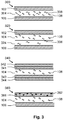
- Fig. 3 schematically shows different examples of stacks of layers falling within the scope of the invention.
- a first example is the stack 300 of layers.
- the stack 300 of layers is similar to the stack 100 of layers of Fig. 1 .
- the stack 300 of layers comprises a luminescent layer 304 in which at least two different particles or molecules 108, 308 of luminescent material are embedded.
- An example is a combination of molecules 108 of an organic phosphor and particles 308 of an inorganic phosphor.
- two different types of organic molecules 108, 308 are present in the luminescent layer 304.
- a second example is the stack 320 of layers.
- the stack 320 of layers is similar to the stack 300 of layers of Fig. 3 .
- the different molecules / particles 108, 308 are arranged in separate luminescent layers 104, 324.
- the luminescent layer 104 is of a matrix polymer in which molecules 108 of an organic luminescent material are dispensed.
- a further luminescent layer 324 is of the same, or another, matrix polymer in which particles 308 of an inorganic luminescent material are dispensed.
- the further luminescent layer 324 comprises molecules 308 of another organic luminescent material.
- the luminescent layer 104 and the further luminescent layer 324 are arranged on top of each other, and the combination of the two luminescent layer 104, 324 is sandwiched in between the first outer layer 102 and the second outer layer 106.
- the first outer layer 102 and the second outer layer 106 are already discussed in the context of Fig. 1 .
- a third example is the stack 340 of layers which comprises the luminescent layer 104 as discussed in the context of Fig. 1 , and which comprises four layers 341, 342, 346, 346.
- a first layer 341 is applied and on top of this first layer 341 a second layer 342 is applied.
- a third layer 343 is applied which is subsequently laminated with a fourth layer 344.
- the subsequent layers are applied on top of each other: the second layer 342, the first layer 341, the luminescent layer 104, the third layer 343 and the fourth layer 344.
- At least the first layer 341 and the second layer 342 are made of a light transmitting polymeric material and have an oxygen transmission rate lower than 30 cm 3 /(m 2 ⁇ day) (STP).
- the second layer 342 and the fourth layer 344 are also made of a light transmitting polymeric material and have an oxygen transmission rate lower than 30 cm 3 /(m 2 ⁇ day) (STP).
- the luminescent layer 104 is protected on both sides, with two layers which prevent the transmission of large amounts of oxygen towards the luminescent layer 104, and, consequently, is the luminescent layer 104 better protected against the influence of oxygen.
- the second layer 342 and the fourth layer 344 are of another light transmitting material (and do not necessarily have an oxygen transmission rate lower than 30 cm 3 /(m 2 ⁇ day) (STP).
- the second layer 342 and the fourth layer 344 are, for example, a (polymeric) color filter.
- a fourth example is the stack 360 of layers which is similar to the stack 100 of layers of Fig. 1 , however, instead of the first outer layer, the stack 360 of layers has a first outer layer 366 which comprises particles 362. Further, the first outer layer 366 is also made of a light transmitting polymeric material and has an oxygen transmission rate lower than 30 cm 3 /(m 2 ⁇ day) (STP).
- the particles 362 which are encapsulated in the light transmitting polymeric material are at least one of: particles of at least one of the groups of scattering particles, lifetime improvement particles and inorganic phosphors.
- scattering particles in the stack of layers 360 In specific applications, in order to obtain specific effects, it is desired to have scattering particles in the stack of layers 360 to obtain a diffuse light emission by the stack 360 of layers and diffuse light transmission through the stack 360 of layers.
- scattering materials are titanium dioxide, zirconium oxide or aluminum oxide particles or a mixture thereof.
- inorganic phosphors results in the generation of additional colors of light and a potentially higher color rendering index.
- lifetime improvement particles are getters which absorb, for example, oxygen which penetrated through one or more layers of the stack 360 of layers - and, thus, the life time of the molecules or particles 108 of luminescent material in the luminescent layer 104 is increased. Getters are a reactive material which absorb other materials (such as gasses) via a chemical reaction.
- stacks 100, 300, 320, 340, 360 of layers illustrate the stack of layers according to the first aspect of the invention.
- the invention is not limited to these individual embodiments only and other combinations of features of the stacks 100, 300, 320, 340, 360 can also be made by the skilled person and still fall within the scope of the invention.
- organic luminescent materials or dyes there is a nearly unlimited assortment of suitable organic luminescent materials or dyes.
- perylenes such as dyes known under their trade name Lumogen from the company BASF, Ludwigshafen, Germany: Lumogen F240 Orange, Lumogen F300 Red Lumogen F305 Red, Lumogen F083 Yellow, Lumogen F170 Yellow, Lumogen F850 Green), Yellow 172 from the company Neelikon Food Dyes & Chemical Ltd., Mumbai, India, and dyes such as coumarins (for example Coumarin 6, Coumarin 7, Coumarin 30, Coumarin 153, Basic Yellow 51), napthalimides (for example Solvent Yellow 11, Solvent Yellow 116), Fluorol 7GA, pyridines (for example pyridine 1), pyrromethenes (such as Pyrromethene 546, Pyrromethene 567), uranine, rhodamines (for example Rhodamine 110, Rhodamine B, Rhodamine 6G, Rhodamine 3B, Rhodamine 101, S
- the luminescent moieties may comprise perylene groups.
- one or more luminescent moieties are configured to generate red luminescence upon excitation by blue and/or UV light.
- the luminescent moieties may for instance comprise a combination of green and red emitting materials, or a combination of yellow and red emitting luminescent materials, etc.
- a light source is applied that (predominantly) generates UV light
- a combination of blue, green and red emitting luminescent moieties, or a combination of blue, yellow and red emitting luminescent moieties, etc. may be applied.
- the inorganic luminescent material may comprises a yellow emitting in organic phosphor, such as YAG and/or LuAG, or a red inorganic phosphor such as ECAS and/or BSSN.
- Other examples of inorganic luminescent materials may include, but are not limited to, cerium doped yttrium aluminum garnet (Y3Al5O12:Ce3+, also referred to as YAG:Ce or Ce doped YAG) or lutetium aluminum garnet (LuAG, Lu3Al5O12), ⁇ -SiAlON:Eu2+ (yellow), and M2Si5N8:Eu2+ (red) wherein M is at least one element selected from calcium Ca, Sr and Ba.
- an inorganic phosphor that may be used in embodiments of the invention, typically in combination with a blue light emitting light source, is YAG:Ce.
- a part of the aluminum may be substituted with gadolinium (Gd) or gallium (Ga), wherein more Gd results in a red shift of the yellow emission.
- suitable materials may include (Sr1 x yBaxCay)2 zSi5 aAlaN8 aOa:Euz2+ wherein 0 ⁇ a ⁇ 5, 0 ⁇ x ⁇ 1, 0 ⁇ y ⁇ 1 and 0 ⁇ z ⁇ 1, and (x+y) ⁇ 1, such as Sr2Si5N8:Eu2+ which emits light in the red range.
- the luminescent materials may comprise quantum dots.
- Quantum dots are small crystals of semiconducting material generally having a width or diameter of only a few nanometers. When excited by incident light, a quantum dot emits light of a color determined by the size and material of the crystal. Light of a particular color can, therefore, be produced by adapting the size of the dots.
- Most known quantum dots with emission in the visible range are based on cadmium selenide (CdSe) with shell such as cadmium sulfide (CdS) and zinc sulfide (ZnS).
- Cadmium free quantum dots such as indium phosphode (InP), and copper indium sulfide (CuInS2) and/or silver indium sulfide (AgInS2) can also be used. Quantum dots show very narrow emission band and thus they show saturated colors. Furthermore, the emission color can easily be tuned by adapting the size of the quantum dots. Any type of quantum dot known in the art may be used in the present invention, provided that it has the appropriate wavelength conversion characteristics.
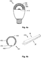
- Fig. 4a and Fig. 4b present examples of a lamp 400, 450 comprising a stack of layers.
- Fig. 4a a cross-sectional view of lamp 400 is presented.
- the lamp 400 is a LED lamp and has the same envelope as a traditional light bulb.
- Lamp 400 comprises a Light Emitting Diode 410 (LED) which emits light towards a stack of layers 402, 404, 406.
- the stack of layers 402, 404, 406 is similar to the stack 100 of layers of Fig. 1 , however, the shape of the stack of layer 402, 404, 406 is not flat, but curved and follows the shape of the light exit window of the lamp 400.
- the first outer layer 402 and the second outer layer 406 are made of a light transmitting polymeric material and have an oxygen transmission rate lower than 30 cm 3 /(m 2 ⁇ day) (STP).
- the luminescent layer 404 which is sandwiched between the first outer layer 402 and the second outer layer 406, is made of a light transmitting matrix polymer and comprises a luminescent material which is configured to absorb light according to an absorption spectrum and to convert a portion of the absorbed light towards light of a light emission spectrum.
- Fig. 4b shows at the right end a three dimensional view of light tube 450 and at the left ends a cross-sectional view of the light tube 450 along lines A-A'.
- an outer glass layer 456 of the light tube 450 is shown.
- a large portion of the glass layer 456 is configured as a light exit window.
- a reflector 454 At a specific position within the glass layer 456 is provided a reflector 454 on top of which a light source 460 comprising a Light Emitting Diode (LED) is arranged.
- the light source 460 emits light towards the light exit window.
- a stack 452 of layers according to the first aspect of the invention is arranged at the light exit window formed by the layer of glass 456.
- the stack 452 of layer is has a curved shape and the layer of the stack 452 follow the curvature of the layer of glass 456.
- the individual layers of the stack 452 are not shown.
- the layers of the stack 452 are for example similar to the layers of the stack 100 of layer of Fig. 1 ; the stack 452 is formed by a first outer layer, a second outer layer and a luminescent layer sandwiched between the first outer layer and the second outer layer. Light which is emitted by the light source 460 first reaches the second outer layer, than the luminescent layer and is finally transferred through the second outer layer to the light exit window formed by layer of layer 456.
- the first outer layer and the second outer layer are of a light transmitting polymeric material and have an oxygen transmission rate lower than 30 cm 3 /(m 2 ⁇ day) (STP).
- the luminescent layer comprises a matrix polymer and a luminescent material being configured to absorb light according to an absorption spectrum and to convert a portion of the absorbed light towards light of a light emission spectrum.
- the light emitter may be a light emitting diode (LED).
- LED light emitting diode
- Other solid state light sources may be used as well, such as an Organic Light Emitting diode(s) OLEDs , or a laser diode.
- the solid state light source may be a blue light emitting LED, such as GaN or InGaN based LED, for example emitting primary light of the wavelength range from 440 to 460 nm.
- the solid state light source may emit UV or violet light which is subsequently converted into light of longer wavelength(s) by one or more wavelength converting materials.
- the LED might also be a direct phosphor converted LED. For instance, a pc-LED having a CCT of 5,000 up to 20,000K can be used.
- Fig. 5a presents in a cross-sectional view a lighting unit 500 which comprises a stack 100 of layers according to the invention.
- the lighting unit 500 comprises a housing 502 which encloses a light mixing cavity 504.
- a light emitter 506 which is, for example, a solid state light emitter.
- solid state light emitters are Light Emitting Diodes (LEDs), Organic Light Emitting diode(s) OLEDs, or, for example, laser diodes.
- the light emitter 506 emits light towards a light exit window of the light mixing cavity 504. At the light exit window is arranged the stack 100 of layers which corresponds to the stack of layers 100 of Fig. 1 .
- the surface of the housing 502, which is facing the light mixing chamber 504, is light reflective.
- the surface may be diffusely or specular light reflective.
- the reflectivity of the surface is at least 80%. In another embodiment, the reflectivity of the surface is at least 90%.
- Fig. 5b presents a luminaire 550 according to the third aspect of the invention.
- the luminaire comprises a stack of layer according to the first aspect of the invention (not shown), a lamp according to the second aspect of the invention (not shown) or one or more the lighting units 500 of Fig. 5a .
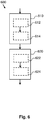
- Fig. 6 presents a method 600 of manufacturing a stack of layers.
- the method 600 comprises the steps of i) manufacturing 610 a luminescent layer of a matrix polymer comprising luminescing material - the luminescent material is configured to absorb light according to an absorption spectrum and to convert a portion of the absorbed light towards light of a light emission spectrum ii) applying 620 a first outer layer and applying a second outer layer on opposite sides of the luminescent layer - the first outer layer and the second outer layer are of a light transmitting polymeric material and have an oxygen transmission rate lower than 30 cm 3 /(m 2 ⁇ day) (STP).
- STP oxygen transmission rate
- the manufacturing 610 of the luminescent layer may comprise the substeps of a) mixing 612 luminescent material with the matrix polymer and b) creating 614 a layer of the mix. Creating 614 a layer may be done by using an extrusion process, by injection molding or extrusion or by spreading the mix along a surface and curing the mix.
- the step of applying 620 a first outer layer and applying a second outer layer on both sides of the luminescent layer comprises c) applying 622 the first outer layer to one surface of the luminescent layer and d) applying 624 the second outer layer to an opposite surface of the luminescent layer.
- the applying 620 of the layers may be performed by using lamination techniques, co-injection molding or co-extrusion.
- any reference signs placed between parentheses shall not be construed as limiting the claim.
- Use of the verb "comprise” and its conjugations does not exclude the presence of elements or steps other than those stated in a claim.
- the article “a” or “an” preceding an element does not exclude the presence of a plurality of such elements.
- the invention may be implemented by means of hardware comprising several distinct elements. In the device claim enumerating several means, several of these means may be embodied by one and the same item of hardware. The mere fact that certain measures are recited in mutually different dependent claims does not indicate that a combination of these measures cannot be used to advantage.
Landscapes
- Engineering & Computer Science (AREA)
- Chemical & Material Sciences (AREA)
- Physics & Mathematics (AREA)
- General Engineering & Computer Science (AREA)
- Materials Engineering (AREA)
- Spectroscopy & Molecular Physics (AREA)
- Organic Chemistry (AREA)
- Wood Science & Technology (AREA)
- Life Sciences & Earth Sciences (AREA)
- Optics & Photonics (AREA)
- Microelectronics & Electronic Packaging (AREA)
- Nanotechnology (AREA)
- Composite Materials (AREA)
- Condensed Matter Physics & Semiconductors (AREA)
- General Physics & Mathematics (AREA)
- Crystallography & Structural Chemistry (AREA)
- Chemical Kinetics & Catalysis (AREA)
- Led Device Packages (AREA)
- Non-Portable Lighting Devices Or Systems Thereof (AREA)
- Optical Filters (AREA)
- Laminated Bodies (AREA)
Abstract
Description
- The invention relates to a stack of layers comprising a layer with a luminescent material.
- In many lighting applications the use of luminescent material in a remote configuration is suggested. Many luminescent materials, and more in particular organic phosphors, have a problem associated with photo-chemical stability. Especially organic phosphors deteriorate when being illuminated and when they are exposed to oxygen. In order to prevent fast deterioration of the material, a protection against oxygen is required. Thus, in order to guarantee a reasonable life time of a light source in which such luminescent materials are used, the luminescent material must be protected against oxygen.
- Other luminescent materials, like quantum dots, are also sensitive for oxygen and deteriorate under the influence of oxygen even without being illuminated.
- In patent
US7839072 a solution is proposed to protect organic phosphors against environmental air. The document discloses a translucent laminate sheet which includes at least one type of organic phosphor which is configured to convert light to another color and two light-transmitting members to seal the organic phosphor. The light-transmitting members are two parallel arranged plates and the organic phosphor is disposed to be held between then. At the circumference of the two plates, the opening between the two plates is hermetically sealed to prevent the deterioration of the organic phosphor under the influence of environmental air. The two plates are made of glass. - The translucent laminate sheet of the cited patent is a relative expensive solution for protecting the organic phosphors. The use of glass and the requirement to hermetically seal the opening between the glass plates at the circumference of the two plates result in a relatively expensive manufacturing process and the use of relatively expensive materials. Further, the use of glass results in a non-flexible configuration and the translucent laminate sheet has a flat shape.
- It is an object of the invention to provide a cost effective solution for protecting a layer with luminescent material against the influence of environmental oxygen.
- A first aspect of the invention provides a stack of layers. A second aspect of the invention provides a lamp, a third aspect of the invention provides a luminaire and a fourth aspect of the invention provides a method of manufacturing a stack of layers. Advantageous embodiments are defined in the dependent claims.
- A stack of layers in accordance with the first aspect of the invention comprises a first outer layer, a second outer layer and a luminescent layer. The first outer layer and the second outer layer are of a light transmitting polymeric material and have an oxygen transmission rate lower than 30 cm3/(m2·day) measured under standard temperature and pressure (STP). The luminescent layer is sandwiched between the first outer layer and the second outer layer and comprises a light transmitting matrix polymer and a luminescent material being configured to absorb light according to an absorption spectrum and convert a portion of the absorbed light towards light of a light emission spectrum, wherein the stack of layers is flexible.
- Providing luminescent material in a matrix polymer in the luminescent layer is a first measure to protect the luminescent material against the influence of environmental air, and more specific, the oxygen in the air. However, the luminescent material, which is present close to the surface of the matrix polymer material, will still receive too much oxygen and will deteriorate. A second measure is the use of two light transmitting layers with barrier properties. By sandwiching the luminescent layer between those two layers, the luminescent material within the luminescent layer is exposed to less oxygen. The two layers with barrier properties form the first outer layer and the second outer layer of the stack of layers and the two outer layers are made of a light transmitting polymeric material. Thus, light may be transmitted through the outer layers. The barrier properties of the outer layers mainly relate to the permeability of the layer for oxygen. The oxygen transmission rate of the first outer layer and of the second outer layer is lower than 30 cm3/(m2·day) under standard temperature and pressure conditions (STP, defined by IUPAC as T = 273.15K and p = 1 bar) and if the oxygen transmission rate is lower than this value, the amount of oxygen which may penetrate through one or more layers of the stack towards the luminescent material is significantly reduced. Thus, the luminescent layer will have a relatively long life time.
- Note that the oxygen transmission rate is the oxygen transmission rate of the layer, which means that, independently of the thickness of the layer, the oxygen transmission rate should be below the specified value. Thus, under standard temperature and pressure conditions, not more than 30 cm3 of oxygen may be transferred through the 1 m2 of such a layer per day. In literature standard measurement setups may be found to measure the transmission rate of a specific gas through a layer. Each material has a specific oxygen permeability which is in general specified by the unit cm3·mm/(m2·day·bar). Thus, the thickness of the layer relates the oxygen transmission rate to the oxygen permeability of the material of which the layer is manufactured and to the pressure difference.
- The term 'sandwiched between' means that the luminescent layer is in between the first outer layer and the second outer layer and that the luminescent layer is applied to these outer layers. It may include situations in which the layers are in direct contact with each other, and may include the use of an adhesive which couples the layers to each other. Other terms that describe the same configuration are: the luminescent layer is coated on opposite sides with the respective outer layers, or the respective outer layers are laminated to opposite sides of the luminescent layer.
- Using a matrix polymer and a light transmitting polymeric material results in several advantages. Suitable materials have a low price and may, thus, result in a cost effective solution for protecting luminescent material. Further, manufacturing method for manufacturing the stack of layers is relatively cheap - the use of polymeric materials allows, for example, the use of co-injection molding and of co-extrusion. Co-injection molding and co-extrusion are a relative cost-effective production method for manufacturing sheets which comprise different layers. Thus, besides the cost-advantage based on the used materials, the suitable manufacturing method leads to an additional cost advantage.
- Other advantages of the use of polymeric material are: the stack of layers can be made flexible, which is advantageous in application wherein the stack of layers is, for example, used in a curved configuration; the stack of layers can also be manufactured in different shapes, such as, for example, the shape of the surface of a tube, the shape of the surface of a sphere, or the shape of a lens. Thus, in addition to the light converting properties of the luminescent material, the stack of layers may be configured to have specific light refraction characteristics.
- Further, the matrix polymer and the light transmitting polymeric material allow an easy cutting of the stack of layers and relatively efficient specific shapes can be cut out of a large sheet of the stack of layers according to the invention. One may, for example, cut circular shapes out of the large sheet for being used in a lamp or luminaire. Alternative techniques for (hermitically) sealing a layer with a luminescent material induce much higher manufacturing costs when such shapes must be manufactured. Further, when the cutting is done by heat, the material of the first outer layer and the second outer layer is welded to each other and automatically forms a sealing at the cutting edges.
- In this context it is to be noted that the used terms "stack" and "layer(s)" do not imply that the claimed stack of layers is flat (follows a flat plane). The use of the term layer implies that the layer is relatively thin compared to its width and length. The term stack implies that two or more layers (in this specific case, three or more layers) are arranged on top of each other. "Layers which are arranged on top of each other" implies that the thinnest dimension of the layers (the thickness) is, locally, arranged in the same direction. In the stack, the layers are not by definition of the same size. In the stack of layers of the invention the luminescent layer is at least sandwiched in between the first outer layer and the second outer layer, which implies that the luminescent layers has the same size (width / length) as the respective outer layers, or is smaller than one or more of the outer layers. The thickness of the layers in the stack of layers may be different.
- In this context, the absorption spectrum and light emission spectrum may, for example, comprise a primary color having a specific bandwidth around a predefined wavelength, or may, for example, comprise a plurality of primary colors. In this context, the spectra may also include non-visible light, such as ultraviolet light. The light of a primary color, for example, includes Red, Green, Blue, Yellow and Amber light. Light of the spectra may also comprise mixtures of primary colors, such as Blue and Amber, or Blue, Yellow and Red.
- The polymeric material of the first outer layer and the second outer layer and of the matrix polymer are at least light transmitting, which means that at least a portion of the light, which impinges on the material, is transmitted through the material and is emitted into the ambient. Thus, the stack of layers may be fully or partially transparent, or may be translucent. In an embodiment, the light transmitting materials transmit at least 80% of the light which penetrates into the material, and only a limited amount of light is absorbed in the stack of layers.
- Optionally, the material of the first outer layer and the material of the second outer layer have an oxygen permeability lower than 3 cm3·mm/(m2·day·bar). Which materials having such a low oxygen permeability it is relatively easy to manufacture stacks of layers of which the first outer layer and the second outer layer have an oxygen transmission rate which is lower than 30 cm3/(m2·day) under standard temperature and pressure (STP).
- Optionally, the luminescent material comprises at least one of an organic phosphor, a quantum dot, a quantum rod or a quantum tetrapod. Organic phosphors deteriorate relatively fast under the influence of oxygen and light. In the stack of layers the organic phosphors are well protected against oxygen against relatively low costs. Quantum dots, quantum rods and quantum tetrapods deteriorate under the influence of oxygen and, thus, the first outer layer and the second outer layer provide an advantageous protection layer for these luminescent materials. The quantum dots, quantum rods and quantum tetrapods are particles showing quantum confinement and have at least in one dimension a size in the nanometer range. Quantum confinement means that the particles have optical properties that depend on the size of the particles.
- Organic phosphors have a high quantum efficiency and are often transparent, which prevents undesired scattering and increases efficiency. Organic luminescent materials have more advantages. The position and the bandwidth of the luminescence spectrum can be designed with ease to be anywhere in the visible range. As such it is relatively easy to manufacture a light source which emits white light with high efficacy.
- Optionally, the luminescent layer comprises a further luminescent material which is configured to absorb light according to a further absorption spectrum and convert a portion of the absorbed light towards light of a further light emission spectrum. Thus, more than one luminescent material is provided in the luminescent layer and the stack of layers also provides an effective and cost efficient protection against oxygen for the further luminescent material. Further, the use of more than one luminescent material allows the generation of more colors of light and, thus, of light emissions with a higher color rendering index.
- Optionally, the luminescent material and the further luminescent material are provided as a mix of materials in a single layer. Alternatively, the luminescent material is provided in a first sub-layer and the further luminescent material is provided in a second sub-layer. The sub-layers form the luminescent layer. Further, in the luminescent layer, two or more different luminescent materials may be separated in space within the luminescent layer, for example, in the form of pixels of one specific color.
- Optionally, the light transmitting polymeric material comprises at least one of: poly ethylene terephthalate (PET), poly ethylene naphtalate (PEN), poly vinylidene chloride (PVDC), poly vinylidene fluoride (PVDF), ethylene vinyl alcohol (EVOH), polybutylene terephthalate (PBT), poly acrylo nitrile (PAN) and nylon6 (PA6). The materials of this optional embodiment are light transmitting and in most cases transparent. Further, they have a relatively low oxygen permeability which is lower than 3 cm3·mm/(m2·day·bar). Thus, the materials are an effective barrier for protecting the luminescent material of the luminescent layer against oxygen. It is to be noted that instead of the term nylon6 the term polycaprolactam may also be used.
- Optionally, the matrix polymer comprises at least one of: poly ethylene terephthalate (PET), poly methylmethacrylate (PMMA), poly carbonate (PC). These materials are light transmitting and it is relatively easy to manufacture a layer of these materials which contains luminescent material. The cost price of these materials is relatively low.
- Optionally, the light transmitting polymeric material and the matrix polymer comprise the same polymeric material.
- Optionally, the light transmitting polymeric material and the matrix polymer comprises poly ethylene terephthalate (PET). PET is a relatively cheap material which forms a sufficient barrier for oxygen in the stack of layers according to the first aspect of the invention. Further, if all layers have the same polymeric material, it is even more efficient to manufacture the stack of layers compared to a situation wherein the material of the respective outer layers is different from the matrix polymer of the luminescent layer. Further, the interface between the different layers will be an interface between layers with an equal refractive index and, consequently, no refraction or undesired reflection occurs at the interface between the different layers.
- Optionally, the first outer layer and/or the luminescent layer further comprises particles of at least one of the groups of scattering particles, lifetime improvement particles and inorganic phosphors. In specific applications, in order to obtain specific effects, it is desired to have scattering particles in the stack of layers to obtain a diffuse light emission by the stack of layers. Further, the use of inorganic phosphors results in the generation of an additional color of light and a potentially higher color rendering index. Examples of lifetime improvement particles are getters which absorb, for example, oxygen which penetrates through one or more layers of the stack of layers - and, thus, the life time of the luminescent material in the luminescent layer is increased. Getters are a reactive material which absorb other materials (such as gasses) via a chemical reaction.
- According to a second aspect of the invention, a lamp is provided which comprises a light emitter and a stack of layers according to the first aspect of the invention. The stack of layers is arranged to receive light from the light emitter.
- According to a third aspect of the invention, a luminaire is provided which comprises a stack of layers according to the first aspect of the invention or comprises a lamp according to the second aspect of the invention.
- The lamp and the luminaire, respectively according to the second aspect and the third aspect of the invention, provide the same benefits as the stack of layers according to the first aspect of the invention and have similar embodiments with similar effects as the corresponding embodiments of the stack.
- According to a fourth aspect of the invention, a method of manufacturing a stack of layers is provided. The method comprises the steps of i) manufacturing a luminescent layer of a matrix polymer comprising luminescing material - the luminescent material is configured to absorb light according to an absorption spectrum and convert a portion of the absorbed light towards light of a light emission spectrum; ii) applying a first outer layer and applying a second outer layer on both sides of the luminescent layer - the first outer layer and the second outer layer are of a light transmitting polymeric material and have an oxygen transmission rate lower than 30 cm3/(m2·day) (STP).
- The manufacturing of the luminescent layer may comprise the sub steps of mixing luminescent material with the matrix polymer and manufacturing a layer of the mix. Creating a layer may be done by using an extrusion process, by injection molding or by spreading the mix along a surface and curing the mix. The step of applying the first outer layer and applying the second outer layer on both sides of the luminescent layer may be performed by using lamination techniques, co-injection molding or co-extrusion.
- The discussed techniques for performing the steps of the method of manufacturing the stack of layers are relatively cheap production technologies and, thus, may result in a relatively cheap stack of layers.
- These and other aspects of the invention are apparent from and will be elucidated with reference to the embodiments described hereinafter.
- It will be appreciated by those skilled in the art that two or more of the above-mentioned options, implementations, and/or aspects of the invention may be combined in any way deemed useful.
- Modifications and variations of the stack and/or the method, which correspond to the described modifications and variations of the stack, can be carried out by a person skilled in the art on the basis of the present description.
- In the drawings:
-
Fig. 1 schematically shows in a cross-sectional view an embodiment of a stack of layers, -
Fig. 2 schematically shows the reduced deterioration as the result of the use of the first outer layer and the second outer layer, -
Fig. 3 schematically shows different examples of stacks of layers falling within the scope of the invention, -
Fig. 4a and Fig. 4b present examples of a lamp comprising a stack of layers, -
Fig. 5a presents in a cross-sectional view a lighting unit which comprises a stack of layers according to the invention, -
Fig. 5b presents a luminaire according to the third aspect of the invention, and -
Fig. 6 presents a method of manufacturing a stack of layers. - It should be noted that items denoted by the same reference numerals in different Figures have the same structural features and the same functions, or are the same signals. Where the function and/or structure of such an item have been explained, there is no necessity for repeated explanation thereof in the detailed description.
- The Figures are purely diagrammatic and not drawn to scale. Particularly for clarity, some dimensions are exaggerated strongly.
-
Fig. 1 schematically shows in a cross-sectional view an embodiment of astack 100 oflayers 102 .. 106. The presented view is only a portion of a large cross-section of, for example, a large sheet which is formed by thestack 100 oflayers 102 .. 106. Thestack 100 of layers comprises aluminescent layer 104 which comprises particles ormolecules 108 of a luminescent material. The particles ormolecules 108 of a luminescent material are embedded in a light transmitting matrix polymer which forms theluminescent layer 104. The particles ormolecules 108 of a luminescent material are configured to absorb light according to an absorption spectrum when light impinges on them and are configured to convert a portion of the absorbed light towards light of a light emission spectrum. The light emission spectrum is different from the light absorption spectrum and, thus, the luminescent material converts light of a specific color to light of another specific color. Thestack 100 of layers further comprises a firstouter layer 102 and a secondouter layer 106. The firstouter layer 102 and the secondouter layer 106 are both manufactured of a light transmitting polymeric material which has an oxygen transmission rate that is lower than 30 cm3/(m2·day) under standard temperature and pressure (STP). Thus, oxygen in the environmental air may penetrate through theouter layer molecules 108 of luminescent material, and, thus, deterioration of the luminescent material of the particles ormolecules 108 is reduced and the life-time of products using the luminescent material for the conversion of the color of light is increased. - When the luminescent material is an organic phosphor, such as for example a perylene derivative, the luminescent material is present in the form of
molecules 108. Luminescent materials based on perylene derivatives are sold by BASF under the name Lumogen. The luminescent material may also beparticles 108 such as quantum dots, quantum rods and quantum tetrapods. The quantum dots, quantum rods and quantum tetrapods are particles showing quantum confinement and have at least in one dimension a size in the nanometer range. Quantum confinement means that the particles have optical properties that depend on the size of the particles. - Oxygen transmission rate (OTR) is the volume of oxygen gas passing through a unit area (m2) of the parallel surfaces of a film / layer / sheet per unit time (day) when the pressure difference between the two sides of the film is 1 bar. The OTR is related to the oxygen permeability P coefficient of a polymer by ORT·d = P, wherein d is the film thickness. Advantageous materials to be used as the matrix polymer of the
luminescent layer 104 are: poly ethylene terephthalate (PET), poly methylmethacrylate (PMMA), poly carbonate (PC). Advantageous material to be used for the firstouter layer 102 and the secondouter layer 106 are: poly ethylene terephthalate (PET - oxygen permeability: 3 cm3·mm/(m2·day·bar), and thus the oxygen transmission rate of 0.1 mm thick amorphous PET is at room temperature 30 cm3/(m2·day)), poly ethylene naphtalate (PEN - oxygen permeability: 0.6 cm3·mm/(m2·day·bar)) , poly vinylidene chloride (PVDC - oxygen permeability: 0.2 cm3·mm/(m2·day·bar)), poly vinylidene fluoride - (PVDF - oxygen permeability: 0.2 cm3·mm/(m2·day·bar)), ethylene vinyl alcohol (EVOH 32% - oxygen permeability: 0.004 cm3·mm/(m2·day·bar)), poly acrylo nitrile (PAN - oxygen permeability: 0.2 cm3·mm/(m2·day·bar)) and nylon6 (polycaprolactam, oxygen permeability: 1.5 cm3·mm/(m2·day·bar)). For PET a minimum layer thickness of 100 micrometer is sufficient to give the desired protection. In case of materials with a lower permeability, the minimum layer thickness may be lower accordingly. It is also possible to use other materials with a higher permeability and just increase the thickness of the layer. However, for practical reasons, it is not always to have relatively thick layers which limit the flexibility and may possibly absorb to much light. - According to a specific embodiment, the same material is used for the matrix polymer of the
luminescent layer 104 as for the firstouter layer 102 and the secondouter layer 106. In an advantageous embodiment, the matrix polymer and the material of the firstouter layer 102 and the secondouter layer 106 are PET. - The effect of the reduced deterioration of the luminescent material is presented in
Fig. 2 which schematically shows, inchart 200, a comparison between aluminescent layer 104 with and withoutouter layers chart 200 represents time. The y-axis represents the normalized intensity. Two different situations are tested. Afirst line 204 represents the situation in which an organic phosphor is provided in a PMMA matrix layer. This layer was exposed by blue light with a flux density of 2W/cm2 at 60 degrees Celsius. A reduction of 10% is measured after a time period t1. Thesecond line 202 represents the situation in which the PMMA layer with the organic phosphor is sandwiched between, which means, laminated with two layers of 100 micrometer transparent poly ethylene terephthalate (PET) foils. After the time period t1 a reduction of intensity of only 2% is measured, which is a significant improvement. -
Fig. 3 schematically shows different examples of stacks of layers falling within the scope of the invention. - A first example is the
stack 300 of layers. Thestack 300 of layers is similar to thestack 100 of layers ofFig. 1 . The difference is that instead of theluminescent layer 104 with a single luminescent material, thestack 300 of layers comprises a luminescent layer 304 in which at least two different particles ormolecules molecules 108 of an organic phosphor andparticles 308 of an inorganic phosphor. In another embodiment, two different types oforganic molecules - A second example is the
stack 320 of layers. Thestack 320 of layers is similar to thestack 300 of layers ofFig. 3 . Instead of a mix ofmolecules 108 of an organic phosphor andparticles 308 of an inorganic phosphor, the different molecules /particles luminescent layers luminescent layer 104 is of a matrix polymer in whichmolecules 108 of an organic luminescent material are dispensed. A furtherluminescent layer 324 is of the same, or another, matrix polymer in whichparticles 308 of an inorganic luminescent material are dispensed. In another embodiment, the furtherluminescent layer 324 comprisesmolecules 308 of another organic luminescent material. Theluminescent layer 104 and the furtherluminescent layer 324 are arranged on top of each other, and the combination of the twoluminescent layer outer layer 102 and the secondouter layer 106. The firstouter layer 102 and the secondouter layer 106 are already discussed in the context ofFig. 1 . - A third example is the
stack 340 of layers which comprises theluminescent layer 104 as discussed in the context ofFig. 1 , and which comprises fourlayers 341, 342, 346, 346. At one side of theluminescent layer 104, a first layer 341 is applied and on top of this first layer 341 asecond layer 342 is applied. At another side of theluminescent layer 104, athird layer 343 is applied which is subsequently laminated with afourth layer 344. Thus, seen in a direction perpendicular to the stack, the subsequent layers are applied on top of each other: thesecond layer 342, the first layer 341, theluminescent layer 104, thethird layer 343 and thefourth layer 344. At least the first layer 341 and thesecond layer 342 are made of a light transmitting polymeric material and have an oxygen transmission rate lower than 30 cm3/(m2·day) (STP). In an embodiment, thesecond layer 342 and thefourth layer 344 are also made of a light transmitting polymeric material and have an oxygen transmission rate lower than 30 cm3/(m2·day) (STP). In this last embodiment, theluminescent layer 104 is protected on both sides, with two layers which prevent the transmission of large amounts of oxygen towards theluminescent layer 104, and, consequently, is theluminescent layer 104 better protected against the influence of oxygen. However, in another embodiment, thesecond layer 342 and thefourth layer 344 are of another light transmitting material (and do not necessarily have an oxygen transmission rate lower than 30 cm3/(m2·day) (STP). Thesecond layer 342 and thefourth layer 344 are, for example, a (polymeric) color filter. - A fourth example is the
stack 360 of layers which is similar to thestack 100 of layers ofFig. 1 , however, instead of the first outer layer, thestack 360 of layers has a firstouter layer 366 which comprisesparticles 362. Further, the firstouter layer 366 is also made of a light transmitting polymeric material and has an oxygen transmission rate lower than 30 cm3/(m2·day) (STP). Theparticles 362 which are encapsulated in the light transmitting polymeric material are at least one of: particles of at least one of the groups of scattering particles, lifetime improvement particles and inorganic phosphors. In specific applications, in order to obtain specific effects, it is desired to have scattering particles in the stack oflayers 360 to obtain a diffuse light emission by thestack 360 of layers and diffuse light transmission through thestack 360 of layers. Examples of scattering materials are titanium dioxide, zirconium oxide or aluminum oxide particles or a mixture thereof. The use of inorganic phosphors results in the generation of additional colors of light and a potentially higher color rendering index. Examples of lifetime improvement particles are getters which absorb, for example, oxygen which penetrated through one or more layers of thestack 360 of layers - and, thus, the life time of the molecules orparticles 108 of luminescent material in theluminescent layer 104 is increased. Getters are a reactive material which absorb other materials (such as gasses) via a chemical reaction. - The examples of
stacks stacks - It is to be noted that, in the examples of the
stacks - There is a nearly unlimited assortment of suitable organic luminescent materials or dyes. Relevant examples are perylenes (such as dyes known under their trade name Lumogen from the company BASF, Ludwigshafen, Germany: Lumogen F240 Orange, Lumogen F300 Red Lumogen F305 Red, Lumogen F083 Yellow, Lumogen F170 Yellow, Lumogen F850 Green), Yellow 172 from the company Neelikon Food Dyes & Chemical Ltd., Mumbai, India, and dyes such as coumarins (for example Coumarin 6, Coumarin 7, Coumarin 30, Coumarin 153, Basic Yellow 51), napthalimides (for example Solvent Yellow 11, Solvent Yellow 116), Fluorol 7GA, pyridines (for example pyridine 1), pyrromethenes (such as Pyrromethene 546, Pyrromethene 567), uranine, rhodamines (for example Rhodamine 110, Rhodamine B, Rhodamine 6G, Rhodamine 3B, Rhodamine 101, Sulphorhodamine 101, Sulphorhodamine 640, Basic Violet 11, Basic Red 2), cyanines (for example phthalocyanine, DCM), stilbenes (for example Bis-MSB, DPS), available from many traders. Several other dyes, such as acid dyes, basic dyes, direct dyes and dispersion dyes may be used as long as they show a sufficiently high fluorescence quantum yield for the intended use. Hence, on or more of the luminescent moieties may comprise perylene groups. Especially, one or more luminescent moieties are configured to generate red luminescence upon excitation by blue and/or UV light.
- Dependent upon the type of light of the light source (see above), the luminescent moieties may for instance comprise a combination of green and red emitting materials, or a combination of yellow and red emitting luminescent materials, etc. In case a light source is applied that (predominantly) generates UV light, a combination of blue, green and red emitting luminescent moieties, or a combination of blue, yellow and red emitting luminescent moieties, etc., may be applied.
- The inorganic luminescent material may comprises a yellow emitting in organic phosphor, such as YAG and/or LuAG, or a red inorganic phosphor such as ECAS and/or BSSN. Other examples of inorganic luminescent materials may include, but are not limited to, cerium doped yttrium aluminum garnet (Y3Al5O12:Ce3+, also referred to as YAG:Ce or Ce doped YAG) or lutetium aluminum garnet (LuAG, Lu3Al5O12), α-SiAlON:Eu2+ (yellow), and M2Si5N8:Eu2+ (red) wherein M is at least one element selected from calcium Ca, Sr and Ba. Another example of an inorganic phosphor that may be used in embodiments of the invention, typically in combination with a blue light emitting light source, is YAG:Ce. Furthermore, a part of the aluminum may be substituted with gadolinium (Gd) or gallium (Ga), wherein more Gd results in a red shift of the yellow emission. Other suitable materials may include (Sr1 x yBaxCay)2 zSi5 aAlaN8 aOa:Euz2+ wherein 0 ≤ a <5, 0 ≤ x ≤1, 0 ≤ y ≤ 1 and 0 < z ≤ 1, and (x+y) ≤ 1, such as Sr2Si5N8:Eu2+ which emits light in the red range.
- In embodiments of the invention the luminescent materials may comprise quantum dots. Quantum dots are small crystals of semiconducting material generally having a width or diameter of only a few nanometers. When excited by incident light, a quantum dot emits light of a color determined by the size and material of the crystal. Light of a particular color can, therefore, be produced by adapting the size of the dots. Most known quantum dots with emission in the visible range are based on cadmium selenide (CdSe) with shell such as cadmium sulfide (CdS) and zinc sulfide (ZnS). Cadmium free quantum dots such as indium phosphode (InP), and copper indium sulfide (CuInS2) and/or silver indium sulfide (AgInS2) can also be used. Quantum dots show very narrow emission band and thus they show saturated colors. Furthermore, the emission color can easily be tuned by adapting the size of the quantum dots. Any type of quantum dot known in the art may be used in the present invention, provided that it has the appropriate wavelength conversion characteristics.
-
Fig. 4a and Fig. 4b present examples of alamp Fig. 4a a cross-sectional view oflamp 400 is presented. Thelamp 400 is a LED lamp and has the same envelope as a traditional light bulb.Lamp 400 comprises a Light Emitting Diode 410 (LED) which emits light towards a stack oflayers layers stack 100 of layers ofFig. 1 , however, the shape of the stack oflayer lamp 400. The firstouter layer 402 and the secondouter layer 406 are made of a light transmitting polymeric material and have an oxygen transmission rate lower than 30 cm3/(m2·day) (STP). The luminescent layer 404, which is sandwiched between the firstouter layer 402 and the secondouter layer 406, is made of a light transmitting matrix polymer and comprises a luminescent material which is configured to absorb light according to an absorption spectrum and to convert a portion of the absorbed light towards light of a light emission spectrum. -
Fig. 4b shows at the right end a three dimensional view oflight tube 450 and at the left ends a cross-sectional view of thelight tube 450 along lines A-A'. In the cross-sectional view, anouter glass layer 456 of thelight tube 450 is shown. A large portion of theglass layer 456 is configured as a light exit window. At a specific position within theglass layer 456 is provided areflector 454 on top of which alight source 460 comprising a Light Emitting Diode (LED) is arranged. Thelight source 460 emits light towards the light exit window. Inside thelight tube 450, astack 452 of layers according to the first aspect of the invention is arranged at the light exit window formed by the layer ofglass 456. Thestack 452 of layer is has a curved shape and the layer of thestack 452 follow the curvature of the layer ofglass 456. The individual layers of thestack 452 are not shown. The layers of thestack 452 are for example similar to the layers of thestack 100 of layer ofFig. 1 ; thestack 452 is formed by a first outer layer, a second outer layer and a luminescent layer sandwiched between the first outer layer and the second outer layer. Light which is emitted by thelight source 460 first reaches the second outer layer, than the luminescent layer and is finally transferred through the second outer layer to the light exit window formed by layer oflayer 456. The first outer layer and the second outer layer are of a light transmitting polymeric material and have an oxygen transmission rate lower than 30 cm3/(m2·day) (STP). The luminescent layer comprises a matrix polymer and a luminescent material being configured to absorb light according to an absorption spectrum and to convert a portion of the absorbed light towards light of a light emission spectrum. - As mentioned above, the light emitter may be a light emitting diode (LED). Other solid state light sources may be used as well, such as an Organic Light Emitting diode(s) OLEDs , or a laser diode. In some embodiments the solid state light source may be a blue light emitting LED, such as GaN or InGaN based LED, for example emitting primary light of the wavelength range from 440 to 460 nm. Alternatively, the solid state light source may emit UV or violet light which is subsequently converted into light of longer wavelength(s) by one or more wavelength converting materials. Nevertheless, the LED might also be a direct phosphor converted LED. For instance, a pc-LED having a CCT of 5,000 up to 20,000K can be used.
-
Fig. 5a presents in a cross-sectional view alighting unit 500 which comprises astack 100 of layers according to the invention. Thelighting unit 500 comprises ahousing 502 which encloses alight mixing cavity 504. Inside thelight mixing cavity 504 is arranged alight emitter 506, which is, for example, a solid state light emitter. Examples of solid state light emitters are Light Emitting Diodes (LEDs), Organic Light Emitting diode(s) OLEDs, or, for example, laser diodes. Thelight emitter 506 emits light towards a light exit window of thelight mixing cavity 504. At the light exit window is arranged thestack 100 of layers which corresponds to the stack oflayers 100 ofFig. 1 . It is to be noted that other embodiments of the stack of layer of, for example,Fig. 3 can also be used in thelighting unit 500. In an embodiment, the surface of thehousing 502, which is facing thelight mixing chamber 504, is light reflective. The surface may be diffusely or specular light reflective. In yet another embodiment, the reflectivity of the surface is at least 80%. In another embodiment, the reflectivity of the surface is at least 90%. -
Fig. 5b presents aluminaire 550 according to the third aspect of the invention. The luminaire comprises a stack of layer according to the first aspect of the invention (not shown), a lamp according to the second aspect of the invention (not shown) or one or more thelighting units 500 ofFig. 5a . -
Fig. 6 presents amethod 600 of manufacturing a stack of layers. Themethod 600 comprises the steps of i) manufacturing 610 a luminescent layer of a matrix polymer comprising luminescing material - the luminescent material is configured to absorb light according to an absorption spectrum and to convert a portion of the absorbed light towards light of a light emission spectrum ii) applying 620 a first outer layer and applying a second outer layer on opposite sides of the luminescent layer - the first outer layer and the second outer layer are of a light transmitting polymeric material and have an oxygen transmission rate lower than 30 cm3/(m2·day) (STP). - The
manufacturing 610 of the luminescent layer may comprise the substeps of a) mixing 612 luminescent material with the matrix polymer and b) creating 614 a layer of the mix. Creating 614 a layer may be done by using an extrusion process, by injection molding or extrusion or by spreading the mix along a surface and curing the mix. The step of applying 620 a first outer layer and applying a second outer layer on both sides of the luminescent layer comprises c) applying 622 the first outer layer to one surface of the luminescent layer and d) applying 624 the second outer layer to an opposite surface of the luminescent layer. The applying 620 of the layers may be performed by using lamination techniques, co-injection molding or co-extrusion. - It should be noted that the above-mentioned embodiments illustrate rather than limit the invention, and that those skilled in the art will be able to design many alternative embodiments without departing from the scope of the appended claims.
- In the claims, any reference signs placed between parentheses shall not be construed as limiting the claim. Use of the verb "comprise" and its conjugations does not exclude the presence of elements or steps other than those stated in a claim. The article "a" or "an" preceding an element does not exclude the presence of a plurality of such elements. The invention may be implemented by means of hardware comprising several distinct elements. In the device claim enumerating several means, several of these means may be embodied by one and the same item of hardware. The mere fact that certain measures are recited in mutually different dependent claims does not indicate that a combination of these measures cannot be used to advantage.
Claims (15)
- A stack of layers (100, 300, 320, 340, 360, 452) comprising- a first outer layer (102, 341, 366, 402),- a second outer layer (106, 343, 406), the first outer layer (102, 341, 366, 402) and the second outer layer (106, 343, 406) are of a light transmitting polymeric material and have an oxygen transmission rate lower than 30 cm3/(m2·day) under standard temperature and pressure (STP), and- a luminescent layer (104, 304, 324, 404) being sandwiched between the first outer layer (102, 341, 366, 402) and the second outer layer (106, 343, 406), the luminescent layer comprises a light transmitting matrix polymer and a luminescent material (108) being configured to absorb light according to an absorption spectrum and convert a portion of the absorbed light towards light of a light emission spectrum, and- wherein the stack of layers (100, 300, 320, 340, 360, 452) is flexible.
- A stack of layers (100, 300, 320, 340, 360, 452) according to claim 1, wherein the stack of layers is arranged in a curved configuration.
- A stack of layers (100, 300, 320, 340, 360, 452) according to claim 1, wherein the light transmitting polymeric material comprises poly ethylene terephthalate - PET, and wherein the luminescent material (108) comprises at least one of a quantum dot, a quantum rod or a quantum tetrapod.
- A stack of layers (100, 300, 320, 340, 360, 452) according to claim 1, wherein the material of the first outer layer (102, 341, 366, 402) and the material of the second outer layer (106, 343, 406) have an oxygen permeability lower than 3 cm3·mm/(m2·day·bar).
- A stack of layers (100, 300, 320, 340, 360, 452) according to claim 1, wherein the luminescent material (108) comprises at least one of an organic phosphor, a quantum dot, a quantum rod or a quantum tetrapod.
- A stack of layers (100, 300, 320, 340, 360, 452) according to claim 1, wherein the luminescent layer (104, 304, 324, 404) comprises a further luminescent material (308) being configured to absorb light according to a further absorption spectrum and convert a portion of the absorbed light towards light of a further light emission spectrum.
- A stack of layers (100, 300, 320, 340, 360, 452) according to claim 5, wherein the luminescent material (108) and the further luminescent material (308) are provided as a mix of materials in a single layer, or wherein the luminescent material (108) is provided in a first sub-layer and the further luminescent material (308) is provided in a second sub-layer.
- A stack of layers (100, 300, 320, 340, 360, 452) according to claim 1, wherein the light transmitting polymeric material comprises at least one of: poly ethylene terephthalate - PET, poly ethylene naphtalate - PEN, poly vinylidene chloride - PVDC, poly vinylidene fluoride - PVDF, ethylene vinyl alcohol - EVOH, polybutylene terephthalate - PBT, poly acrylo nitrile - PAN and nylon6 - PA6.
- A stack of layers (100, 300, 320, 340, 360, 452) according to claim 1, wherein the matrix polymer comprises at least one of: poly ethylene terephthalate - PET, poly methylmethacrylate - PMMA, poly carbonate - PC.
- A stack of layers (100, 300, 320, 340, 360, 452) according to claim 1, wherein the light transmitting polymeric material and the matrix polymer comprise the same polymeric material.
- A stack of layers (100, 300, 320, 340, 360, 452) according to claim 10, wherein the light transmitting polymeric material and the matrix polymer comprises poly ethylene terephthalate - PET.
- A stack of layers (100, 300, 320, 340, 360, 452) according to claim 1, wherein the first outer layer (102, 341, 366, 402) and/or the luminescent layer (104, 304, 324, 404) further comprises particles (362) of at least one of the groups of scattering particles, lifetime improvement particles and inorganic phosphors.
- A lamp (400, 450, 500) comprising a light emitter (410, 460, 506) and a stack of layers (100, 300, 320, 340, 360, 452) according to claim 1 arranged to receive light from the light emitter (410, 460, 506).
- A luminaire (550) comprising a stack of layers (100, 300, 320, 340, 360, 452) according to claim 1 or comprising a lamp (400, 450, 500) according to claim 13.
- A method (600) of manufacturing a stack of layers,- manufacturing (610) a luminescent layer of a matrix polymer comprising luminescing material, the luminescent material is configured to absorb light according to an absorption spectrum and to convert a portion of the absorbed light towards light of a light emission spectrum,- applying (620) a first outer layer and applying a second outer layer on opposite sides of the luminescent layer, the first outer layer and the second outer layer are of a light transmitting polymeric material and have an oxygen transmission rate lower than 30 cm3/(m2·day) under standard temperature and pressure (STP).
Applications Claiming Priority (3)
| Application Number | Priority Date | Filing Date | Title |
|---|---|---|---|
| US201261668052P | 2012-07-05 | 2012-07-05 | |
| PCT/IB2013/055511 WO2014006597A1 (en) | 2012-07-05 | 2013-07-05 | A stack of layers comprising luminescent material, a lamp, a luminaire and a method of manufacturing the stack of layers |
| EP13762576.0A EP2870831B1 (en) | 2012-07-05 | 2013-07-05 | A stack of layers comprising luminescent material, a lamp, a luminaire and a method of manufacturing the stack of layers |
Related Parent Applications (2)
| Application Number | Title | Priority Date | Filing Date |
|---|---|---|---|
| EP13762576.0A Division-Into EP2870831B1 (en) | 2012-07-05 | 2013-07-05 | A stack of layers comprising luminescent material, a lamp, a luminaire and a method of manufacturing the stack of layers |
| EP13762576.0A Division EP2870831B1 (en) | 2012-07-05 | 2013-07-05 | A stack of layers comprising luminescent material, a lamp, a luminaire and a method of manufacturing the stack of layers |
Publications (1)
| Publication Number | Publication Date |
|---|---|
| EP3742868A1 true EP3742868A1 (en) | 2020-11-25 |
Family
ID=49170765
Family Applications (2)
| Application Number | Title | Priority Date | Filing Date |
|---|---|---|---|
| EP13762576.0A Active EP2870831B1 (en) | 2012-07-05 | 2013-07-05 | A stack of layers comprising luminescent material, a lamp, a luminaire and a method of manufacturing the stack of layers |
| EP20170145.5A Pending EP3742868A1 (en) | 2012-07-05 | 2013-07-05 | A stack of layers comprising luminescent material, a lamp, a luminaire and a method of manufacturing the stack of layers |
Family Applications Before (1)
| Application Number | Title | Priority Date | Filing Date |
|---|---|---|---|
| EP13762576.0A Active EP2870831B1 (en) | 2012-07-05 | 2013-07-05 | A stack of layers comprising luminescent material, a lamp, a luminaire and a method of manufacturing the stack of layers |
Country Status (8)
| Country | Link |
|---|---|
| US (1) | US9631793B2 (en) |
| EP (2) | EP2870831B1 (en) |
| JP (1) | JP6636324B2 (en) |
| CN (1) | CN104412712B (en) |
| ES (1) | ES2813338T3 (en) |
| PL (1) | PL2870831T3 (en) |
| RU (1) | RU2633765C2 (en) |
| WO (1) | WO2014006597A1 (en) |
Families Citing this family (18)
| Publication number | Priority date | Publication date | Assignee | Title |
|---|---|---|---|---|
| ES2629579T3 (en) * | 2014-02-21 | 2017-08-11 | Philips Lighting Holding B.V. | A light emission module, a lamp, a luminaire and a method of lighting an object |
| JP6330902B2 (en) * | 2014-04-04 | 2018-05-30 | 凸版印刷株式会社 | Wavelength conversion sheet and backlight unit |
| JP6326003B2 (en) * | 2014-05-19 | 2018-05-16 | 富士フイルム株式会社 | Wavelength conversion member, backlight unit, liquid crystal display device, and quantum dot-containing polymerizable composition |
| JP6159351B2 (en) * | 2014-05-19 | 2017-07-05 | 富士フイルム株式会社 | Wavelength conversion member, backlight unit, liquid crystal display device, and method of manufacturing wavelength conversion member |
| JP2016103461A (en) * | 2014-11-14 | 2016-06-02 | 富士フイルム株式会社 | Wavelength conversion member, backlight unit and liquid crystal display device |
| JP6431749B2 (en) * | 2014-11-14 | 2018-11-28 | 富士フイルム株式会社 | Functional laminated film |
| EP3667746B1 (en) * | 2014-12-26 | 2023-12-06 | Toppan Inc. | Method for manufacturing a wavelength conversion member |
| US10962705B2 (en) * | 2015-01-31 | 2021-03-30 | Lg Chem, Ltd. | Color conversion film and back light unit and display apparatus comprising the same |
| EP3338310A4 (en) * | 2015-08-17 | 2019-02-27 | Infinite Arthroscopy Inc, Limited | LIGHT SOURCE |
| JP6509091B2 (en) * | 2015-10-20 | 2019-05-08 | 富士フイルム株式会社 | Wavelength conversion laminated film |
| KR102151510B1 (en) * | 2016-07-20 | 2020-09-03 | 후지필름 가부시키가이샤 | Quantum dot-containing composition, wavelength conversion member, backlight unit, and liquid crystal display device |
| WO2018211304A1 (en) | 2017-05-18 | 2018-11-22 | Eni S.P.A. | Polymeric composition comprising a fluorescent dye, its process of preparation, use and object comprising it |
| JP7387949B2 (en) * | 2017-10-16 | 2023-11-29 | Toppanホールディングス株式会社 | Quantum dot-containing resin sheet or film, manufacturing method thereof, and wavelength conversion member |
| JP6481987B1 (en) * | 2018-01-24 | 2019-03-13 | ベスパック株式会社 | Lighting cover for white LED light source and manufacturing method |
| EP3757629B1 (en) * | 2018-02-19 | 2024-03-06 | NGK Insulators, Ltd. | Optical component and illuminating device |
| DE102018214373B4 (en) * | 2018-08-24 | 2020-03-26 | Technische Universität Dresden | LUMINOUS LIGHTING DEVICE FOR TRANSPORT MEANS, METHOD FOR OPERATING A LIGHTING DEVICE AND TRANSPORT MEANS WITH A LIGHTING DEVICE |
| WO2020193572A1 (en) * | 2019-03-28 | 2020-10-01 | Signify Holding B.V. | Multi-layer pcb stack for color mixing |
| US20220032578A1 (en) * | 2020-07-31 | 2022-02-03 | Asterios Saios | Multilayer plastic film for agricultural use |
Citations (4)
| Publication number | Priority date | Publication date | Assignee | Title |
|---|---|---|---|---|
| EP1947707A1 (en) * | 2005-10-27 | 2008-07-23 | Konica Minolta Holdings, Inc. | Organic electroluminescent element, liquid crystal display device, and lighting equipment |
| US7839072B2 (en) | 2006-05-24 | 2010-11-23 | Citizen Electronics Co., Ltd. | Translucent laminate sheet and light-emitting device using the translucent laminate sheet |
| US20110037926A1 (en) * | 2008-04-25 | 2011-02-17 | Sony Corporation | Light emitting device, display device, and color conversion sheet |
| WO2012085780A1 (en) * | 2010-12-21 | 2012-06-28 | Koninklijke Philips Electronics N.V. | Lighting device with polymer containing matrices |
Family Cites Families (18)
| Publication number | Priority date | Publication date | Assignee | Title |
|---|---|---|---|---|
| AUPR399501A0 (en) * | 2001-03-27 | 2001-04-26 | Silverbrook Research Pty. Ltd. | An apparatus and method(ART107) |
| WO2003107441A2 (en) * | 2002-06-13 | 2003-12-24 | Cree, Inc. | Saturated phosphor solid emitter |
| SE0402197D0 (en) * | 2004-09-10 | 2004-09-10 | Tetra Laval Holdings & Finance | A polymer film, a packaging laminate comprising the polymer film, a packaging container formed from the packaging laminate and a process for the production of the polymer film |
| JP2006135225A (en) * | 2004-11-09 | 2006-05-25 | Toshiba Corp | Light emitting device |
| JP2007273498A (en) * | 2006-03-30 | 2007-10-18 | Kyocera Corp | Wavelength converter and light emitting device |
| JP2007317787A (en) * | 2006-05-24 | 2007-12-06 | Citizen Electronics Co Ltd | Light emitting device and manufacturing method thereof |
| KR101458077B1 (en) | 2008-05-01 | 2014-11-04 | 삼성전자 주식회사 | Light emitting device and method of manufacturing the same |
| EP2409340B1 (en) | 2009-03-19 | 2019-06-12 | Signify Holding B.V. | Color adjusting arrangements and illumination device with the same |
| EP2417219B1 (en) | 2009-04-06 | 2013-05-29 | Koninklijke Philips Electronics N.V. | Luminescent converter for a phosphor- enhanced light source comprising organic and inorganic phosphors |
| JP5255527B2 (en) * | 2009-07-03 | 2013-08-07 | デクセリアルズ株式会社 | Color conversion member and display device |
| JP5508795B2 (en) * | 2009-09-18 | 2014-06-04 | 株式会社Adeka | Pendant polymer compound, color conversion film using pendant polymer compound, and multicolor organic EL device |
| RU96929U1 (en) * | 2010-04-19 | 2010-08-20 | Общество с ограниченной ответственностью "АС и ПП" | ENERGY SAVING LIGHT |
| US20130334956A1 (en) | 2010-05-05 | 2013-12-19 | Next Lighting Coro. | Remote phosphor tape lighting units |
| WO2011158144A1 (en) | 2010-06-18 | 2011-12-22 | Koninklijke Philips Electronics N.V. | Light generating method |
| JP5766411B2 (en) * | 2010-06-29 | 2015-08-19 | 日東電工株式会社 | Phosphor layer and light emitting device |
| EP2588798B8 (en) | 2010-07-01 | 2016-09-21 | Philips Lighting Holding B.V. | Led module |
| CN101937974A (en) * | 2010-07-06 | 2011-01-05 | 电子科技大学 | Packaging structure and packaging method of a flexible organic electroluminescent device |
| EP2622272A2 (en) * | 2010-09-28 | 2013-08-07 | Koninklijke Philips Electronics N.V. | Light-emitting arrangement |
-
2013
- 2013-07-05 WO PCT/IB2013/055511 patent/WO2014006597A1/en not_active Ceased
- 2013-07-05 EP EP13762576.0A patent/EP2870831B1/en active Active
- 2013-07-05 CN CN201380035663.0A patent/CN104412712B/en active Active
- 2013-07-05 PL PL13762576T patent/PL2870831T3/en unknown
- 2013-07-05 EP EP20170145.5A patent/EP3742868A1/en active Pending
- 2013-07-05 US US14/409,026 patent/US9631793B2/en active Active
- 2013-07-05 ES ES13762576T patent/ES2813338T3/en active Active
- 2013-07-05 JP JP2015519479A patent/JP6636324B2/en active Active
- 2013-07-05 RU RU2015103728A patent/RU2633765C2/en active
Patent Citations (4)
| Publication number | Priority date | Publication date | Assignee | Title |
|---|---|---|---|---|
| EP1947707A1 (en) * | 2005-10-27 | 2008-07-23 | Konica Minolta Holdings, Inc. | Organic electroluminescent element, liquid crystal display device, and lighting equipment |
| US7839072B2 (en) | 2006-05-24 | 2010-11-23 | Citizen Electronics Co., Ltd. | Translucent laminate sheet and light-emitting device using the translucent laminate sheet |
| US20110037926A1 (en) * | 2008-04-25 | 2011-02-17 | Sony Corporation | Light emitting device, display device, and color conversion sheet |
| WO2012085780A1 (en) * | 2010-12-21 | 2012-06-28 | Koninklijke Philips Electronics N.V. | Lighting device with polymer containing matrices |
Also Published As
| Publication number | Publication date |
|---|---|
| EP2870831A1 (en) | 2015-05-13 |
| CN104412712B (en) | 2017-09-01 |
| EP2870831B1 (en) | 2020-06-17 |
| US20150192273A1 (en) | 2015-07-09 |
| US9631793B2 (en) | 2017-04-25 |
| ES2813338T3 (en) | 2021-03-23 |
| JP6636324B2 (en) | 2020-01-29 |
| JP2015530606A (en) | 2015-10-15 |
| WO2014006597A9 (en) | 2014-09-12 |
| WO2014006597A1 (en) | 2014-01-09 |
| PL2870831T3 (en) | 2020-11-30 |
| RU2015103728A (en) | 2016-08-27 |
| CN104412712A (en) | 2015-03-11 |
| RU2633765C2 (en) | 2017-10-18 |
Similar Documents
| Publication | Publication Date | Title |
|---|---|---|
| EP2870831B1 (en) | A stack of layers comprising luminescent material, a lamp, a luminaire and a method of manufacturing the stack of layers | |
| EP2835036B1 (en) | A light emitting assembly, a lamp and a luminaire | |
| JP5431320B2 (en) | Optical element having internal optical function and method for manufacturing the same | |
| US9803809B2 (en) | Stabilized wavelength converting element | |
| EP2847511B1 (en) | Light emitting arrangement | |
| EP2705545B1 (en) | Phosphor-enhanced lighting device, retrofit light bulb and light tube with reduced color appearance | |
| WO2013057660A2 (en) | Light emitting arrangement | |
| EP2655545B1 (en) | Light converter device and lighting device with polymer containing matrices | |
| EP2732006B1 (en) | Wavelength converting element | |
| CN104221172A (en) | A light conversion assembly, a lamp and a luminaire | |
| EP2788673A2 (en) | Light-emitting arrangement | |
| US9746159B1 (en) | Lighting system having a sealing system |
Legal Events
| Date | Code | Title | Description |
|---|---|---|---|
| PUAI | Public reference made under article 153(3) epc to a published international application that has entered the european phase |
Free format text: ORIGINAL CODE: 0009012 |
|
| STAA | Information on the status of an ep patent application or granted ep patent |
Free format text: STATUS: THE APPLICATION HAS BEEN PUBLISHED |
|
| AC | Divisional application: reference to earlier application |
Ref document number: 2870831 Country of ref document: EP Kind code of ref document: P |
|
| AK | Designated contracting states |
Kind code of ref document: A1 Designated state(s): AL AT BE BG CH CY CZ DE DK EE ES FI FR GB GR HR HU IE IS IT LI LT LU LV MC MK MT NL NO PL PT RO RS SE SI SK SM TR |
|
| STAA | Information on the status of an ep patent application or granted ep patent |
Free format text: STATUS: REQUEST FOR EXAMINATION WAS MADE |
|
| 17P | Request for examination filed |
Effective date: 20210525 |
|
| RBV | Designated contracting states (corrected) |
Designated state(s): AL AT BE BG CH CY CZ DE DK EE ES FI FR GB GR HR HU IE IS IT LI LT LU LV MC MK MT NL NO PL PT RO RS SE SI SK SM TR |
|
| STAA | Information on the status of an ep patent application or granted ep patent |
Free format text: STATUS: EXAMINATION IS IN PROGRESS |
|
| 17Q | First examination report despatched |
Effective date: 20230607 |
|
| GRAP | Despatch of communication of intention to grant a patent |
Free format text: ORIGINAL CODE: EPIDOSNIGR1 |
|
| STAA | Information on the status of an ep patent application or granted ep patent |
Free format text: STATUS: GRANT OF PATENT IS INTENDED |
|
| RIC1 | Information provided on ipc code assigned before grant |
Ipc: H05B 33/14 20060101AFI20260513BHEP Ipc: H01J 1/68 20060101ALI20260513BHEP Ipc: H01J 1/63 20060101ALI20260513BHEP Ipc: F21V 13/08 20060101ALI20260513BHEP Ipc: F21V 9/38 20180101ALI20260513BHEP Ipc: F21V 9/32 20180101ALI20260513BHEP Ipc: F21V 3/12 20180101ALI20260513BHEP Ipc: F21S 8/06 20060101ALI20260513BHEP Ipc: F21K 9/64 20160101ALI20260513BHEP Ipc: F21K 9/27 20160101ALI20260513BHEP Ipc: F21K 9/232 20160101ALI20260513BHEP Ipc: B82Y 30/00 20110101ALI20260513BHEP Ipc: H05B 33/04 20060101ALI20260513BHEP Ipc: H10H 20/851 20250101ALI20260513BHEP |
|
| INTG | Intention to grant announced |
Effective date: 20260616 |