EP3742753B1 - Hearing protection devices, noise exposure sensors therefor, and sensor housings and associated methods for the same - Google Patents
Hearing protection devices, noise exposure sensors therefor, and sensor housings and associated methods for the same Download PDFInfo
- Publication number
- EP3742753B1 EP3742753B1 EP19176573.4A EP19176573A EP3742753B1 EP 3742753 B1 EP3742753 B1 EP 3742753B1 EP 19176573 A EP19176573 A EP 19176573A EP 3742753 B1 EP3742753 B1 EP 3742753B1
- Authority
- EP
- European Patent Office
- Prior art keywords
- housing
- microphone
- noise sensor
- axial bore
- ear cup
- Prior art date
- Legal status (The legal status is an assumption and is not a legal conclusion. Google has not performed a legal analysis and makes no representation as to the accuracy of the status listed.)
- Active
Links
Images




Classifications
-
- A—HUMAN NECESSITIES
- A61—MEDICAL OR VETERINARY SCIENCE; HYGIENE
- A61F—FILTERS IMPLANTABLE INTO BLOOD VESSELS; PROSTHESES; DEVICES PROVIDING PATENCY TO, OR PREVENTING COLLAPSING OF, TUBULAR STRUCTURES OF THE BODY, e.g. STENTS; ORTHOPAEDIC, NURSING OR CONTRACEPTIVE DEVICES; FOMENTATION; TREATMENT OR PROTECTION OF EYES OR EARS; BANDAGES, DRESSINGS OR ABSORBENT PADS; FIRST-AID KITS
- A61F11/00—Methods or devices for treatment of the ears or hearing sense; Non-electric hearing aids; Methods or devices for enabling ear patients to achieve auditory perception through physiological senses other than hearing sense; Protective devices for the ears, carried on the body or in the hand
- A61F11/06—Protective devices for the ears
- A61F11/14—Protective devices for the ears external, e.g. earcaps or earmuffs
-
- A—HUMAN NECESSITIES
- A61—MEDICAL OR VETERINARY SCIENCE; HYGIENE
- A61F—FILTERS IMPLANTABLE INTO BLOOD VESSELS; PROSTHESES; DEVICES PROVIDING PATENCY TO, OR PREVENTING COLLAPSING OF, TUBULAR STRUCTURES OF THE BODY, e.g. STENTS; ORTHOPAEDIC, NURSING OR CONTRACEPTIVE DEVICES; FOMENTATION; TREATMENT OR PROTECTION OF EYES OR EARS; BANDAGES, DRESSINGS OR ABSORBENT PADS; FIRST-AID KITS
- A61F11/00—Methods or devices for treatment of the ears or hearing sense; Non-electric hearing aids; Methods or devices for enabling ear patients to achieve auditory perception through physiological senses other than hearing sense; Protective devices for the ears, carried on the body or in the hand
- A61F11/06—Protective devices for the ears
- A61F11/14—Protective devices for the ears external, e.g. earcaps or earmuffs
- A61F11/145—Protective devices for the ears external, e.g. earcaps or earmuffs electric, e.g. for active noise reduction
-
- H—ELECTRICITY
- H04—ELECTRIC COMMUNICATION TECHNIQUE
- H04R—LOUDSPEAKERS, MICROPHONES, GRAMOPHONE PICK-UPS OR LIKE ACOUSTIC ELECTROMECHANICAL TRANSDUCERS; ELECTRIC HEARING AIDS; PUBLIC ADDRESS SYSTEMS
- H04R1/00—Details of transducers, loudspeakers or microphones
- H04R1/10—Earpieces; Attachments therefor ; Earphones; Monophonic headphones
- H04R1/1008—Earpieces of the supra-aural or circum-aural type
-
- H—ELECTRICITY
- H04—ELECTRIC COMMUNICATION TECHNIQUE
- H04R—LOUDSPEAKERS, MICROPHONES, GRAMOPHONE PICK-UPS OR LIKE ACOUSTIC ELECTROMECHANICAL TRANSDUCERS; ELECTRIC HEARING AIDS; PUBLIC ADDRESS SYSTEMS
- H04R1/00—Details of transducers, loudspeakers or microphones
- H04R1/10—Earpieces; Attachments therefor ; Earphones; Monophonic headphones
- H04R1/1058—Manufacture or assembly
- H04R1/1075—Mountings of transducers in earphones or headphones
-
- H—ELECTRICITY
- H04—ELECTRIC COMMUNICATION TECHNIQUE
- H04R—LOUDSPEAKERS, MICROPHONES, GRAMOPHONE PICK-UPS OR LIKE ACOUSTIC ELECTROMECHANICAL TRANSDUCERS; ELECTRIC HEARING AIDS; PUBLIC ADDRESS SYSTEMS
- H04R1/00—Details of transducers, loudspeakers or microphones
- H04R1/20—Arrangements for obtaining desired frequency or directional characteristics
- H04R1/22—Arrangements for obtaining desired frequency or directional characteristics for obtaining desired frequency characteristic only
- H04R1/28—Transducer mountings or enclosures modified by provision of mechanical or acoustic impedances, e.g. resonator, damping means
- H04R1/2869—Reduction of undesired resonances, i.e. standing waves within enclosure, or of undesired vibrations, i.e. of the enclosure itself
- H04R1/2876—Reduction of undesired resonances, i.e. standing waves within enclosure, or of undesired vibrations, i.e. of the enclosure itself by means of damping material, e.g. as cladding
-
- H—ELECTRICITY
- H04—ELECTRIC COMMUNICATION TECHNIQUE
- H04R—LOUDSPEAKERS, MICROPHONES, GRAMOPHONE PICK-UPS OR LIKE ACOUSTIC ELECTROMECHANICAL TRANSDUCERS; ELECTRIC HEARING AIDS; PUBLIC ADDRESS SYSTEMS
- H04R1/00—Details of transducers, loudspeakers or microphones
- H04R1/20—Arrangements for obtaining desired frequency or directional characteristics
- H04R1/22—Arrangements for obtaining desired frequency or directional characteristics for obtaining desired frequency characteristic only
- H04R1/28—Transducer mountings or enclosures modified by provision of mechanical or acoustic impedances, e.g. resonator, damping means
- H04R1/2869—Reduction of undesired resonances, i.e. standing waves within enclosure, or of undesired vibrations, i.e. of the enclosure itself
- H04R1/2876—Reduction of undesired resonances, i.e. standing waves within enclosure, or of undesired vibrations, i.e. of the enclosure itself by means of damping material, e.g. as cladding
- H04R1/288—Reduction of undesired resonances, i.e. standing waves within enclosure, or of undesired vibrations, i.e. of the enclosure itself by means of damping material, e.g. as cladding for loudspeaker transducers
-
- H—ELECTRICITY
- H04—ELECTRIC COMMUNICATION TECHNIQUE
- H04R—LOUDSPEAKERS, MICROPHONES, GRAMOPHONE PICK-UPS OR LIKE ACOUSTIC ELECTROMECHANICAL TRANSDUCERS; ELECTRIC HEARING AIDS; PUBLIC ADDRESS SYSTEMS
- H04R29/00—Monitoring arrangements; Testing arrangements
- H04R29/004—Monitoring arrangements; Testing arrangements for microphones
-
- H—ELECTRICITY
- H04—ELECTRIC COMMUNICATION TECHNIQUE
- H04R—LOUDSPEAKERS, MICROPHONES, GRAMOPHONE PICK-UPS OR LIKE ACOUSTIC ELECTROMECHANICAL TRANSDUCERS; ELECTRIC HEARING AIDS; PUBLIC ADDRESS SYSTEMS
- H04R1/00—Details of transducers, loudspeakers or microphones
- H04R1/08—Mouthpieces; Microphones; Attachments therefor
- H04R1/083—Special constructions of mouthpieces
- H04R1/086—Protective screens, e.g. all weather or wind screens
-
- H—ELECTRICITY
- H04—ELECTRIC COMMUNICATION TECHNIQUE
- H04R—LOUDSPEAKERS, MICROPHONES, GRAMOPHONE PICK-UPS OR LIKE ACOUSTIC ELECTROMECHANICAL TRANSDUCERS; ELECTRIC HEARING AIDS; PUBLIC ADDRESS SYSTEMS
- H04R1/00—Details of transducers, loudspeakers or microphones
- H04R1/10—Earpieces; Attachments therefor ; Earphones; Monophonic headphones
- H04R1/1083—Reduction of ambient noise
-
- H—ELECTRICITY
- H04—ELECTRIC COMMUNICATION TECHNIQUE
- H04R—LOUDSPEAKERS, MICROPHONES, GRAMOPHONE PICK-UPS OR LIKE ACOUSTIC ELECTROMECHANICAL TRANSDUCERS; ELECTRIC HEARING AIDS; PUBLIC ADDRESS SYSTEMS
- H04R2410/00—Microphones
- H04R2410/05—Noise reduction with a separate noise microphone
Definitions
- hearing protection devices such as earmuffs are often used to protect a wearer's ears from excessive noise exposure.
- Such hearing protection devices often provide a passive and/or active noise dampening or noise cancellation effect for the wearer, often in an effort to reduce the total noise exposure for a wearer to below a regulated or suggested acute or chronic exposure limit.
- one or more noise sensors can be placed in or about the hearing protection device.
- noise sensors are often susceptible to damage from exposure to dust and other contaminants, often measure noise exposure in a manner that is not true to the wearer's actual exposure, are costly to manufacture, require significant space within the hearing device, and often cannot be calibrated reliably and/or without substantial disassembly of the hearing protection device.
- WO 2006/118516 discloses an ear cup with a microphone apparatus which comprises an inner cup portion, for forming a noise damping space, and an outer cup portion for forming a space for accommodating electronics and/or a current source.
- the inner cup portion and the outer cup portion are separated by a partition.
- the inner cup portion has a pocket and two opposingly located recesses in which a bracket for a microphone is disposed.
- a windshield is provided, this protecting the microphone from being damaged and also damping wind noise.
- the windshield has an outer configuration that may be seen as a continuation of the outer cup portion, in order to prevent turbulence in the region of the windshield.
- the windshield is produced from a porous material, which is surrounded by a mounting frame having nap catches for engagement in snap catches;
- US 2010/303270 discloses a hearing protection system with talk-through having a pair of rigid earcups enclosing a microphone, amplifier and speaker.
- a concha simulator having a volume simulating that of the concha of a human ear, is acoustically coupled to the microphone, and also to the outside through an opening in the earcup. By coupling the microphone to the concha simulator, instead of directly to the outside, the acoustic response of the talk-through more accurately represents the hearing of a user.
- a noise sensor assembly for a hearing protection device, the noise sensor assembly comprising: a printed circuit board (PCB); a noise sensor comprising a microphone mounted on the PCB and electrically coupled to the PCB; a housing dimensioned and configured to be fixably disposed at or proximate an aperture defined in an outer surface of an external casing of the hearing protection device, wherein the housing comprises an inner surface defining an axial bore, wherein a distal end of the axial bore is configured to acoustically communicate with an external environment via the aperture, wherein the housing defines a noise sensor receiving portion comprising a slot configured to engage the PCB (114) on which the microphone is mounted and to which the microphone is electrically coupled, wherein the slot of the housing is configured to retain the microphone, such that the microphone faces the axial bore, wherein in an instance in which the noise sensor is engaged with the housing, the noise sensor is sealed against the housing.
- PCB printed circuit board
- a noise sensor comprising a microphone mounted on the PCB and electrically coupled to the PC
- the axial bore of the housing is dimensioned and configured to slidably receive a calibration tool to form an airtight seal with the inner surface of the housing.
- the housing can further define a securing portion at a distal end, the securing portion adapted to contact and secure the housing with respect to a portion of the outer surface of the hearing protection device.
- the noise sensor assembly can further comprise an internal dust protector disposed between the noise sensor receiving portion of the housing and the noise sensor, and wherein the internal dust protector is disposed between the microphone and the axial bore.
- the housing comprises at least one of a vibration attenuation material and a noise dampening material. In some embodiments, in an instance in which the noise sensor is engaged with the housing, the noise sensor is retained within the noise senor receiving portion and abuts the slot.
- an ear cup for a hearing protection device comprising: an external casing defining an aperture; a printed circuit board (PCB); a noise sensor comprising a microphone mounted on the PCB and electrically coupled to the PCB; and a housing fixably disposed at or proximate the aperture defined by the external casing, wherein the housing comprises an inner surface defining an axial bore, wherein a distal end of the axial bore is configured to acoustically communicate with an external environment via the aperture, wherein the housing defines a noise sensor receiving portion comprising a slot configured to engage the PCB (114) on which the microphone is mounted and to which the microphone is electrically coupled, wherein the slot of the housing is configured to retain the microphone, such that the microphone faces the axial bore, wherein in an instance in which the noise sensor is engaged with the housing, the noise sensor is sealed against the housing, and the noise sensor and the housing seal the aperture defined by the external casing.
- PCB printed circuit board
- the ear cup can further comprise a removable securing collar.
- the external casing comprises a first portion and a second portion, the second portion defining the aperture configured to sealably retain the removable securing collar, the second portion configured to sealably engage the first portion such that the first portion, the second portion, and the removable securing collar seal the aperture in the external casing.
- the noise sensor receiving portion of the axial bore has a first inner diameter and the distal end portion of the axial bore has a second inner diameter less than the first inner diameter.
- the ear cup can further comprise a removable sealing collar configured to sealably retain the housing at or proximate the aperture defined by the external casing, the removable securing collar comprising an opening such that the distal end of the axial bore of the housing is configured to acoustically communicate with the external environment via the aperture of the external casing and the opening of the removable sealing collar.
- the ear cup can further comprise a removable sealing collar configured to be retained by the aperture, wherein the axial bore of the housing is configured such that when the removable securing collar is removed and the calibration tool is slidably inserted into the axial bore of the housing, the calibration tool forms an airtight seal with an inner surface of the axial bore of the housing.
- the ear cup can further comprise an external dust protector disposed between the housing and the removable securing collar.
- the housing further comprises a securing portion disposed about the axial bore, the securing portion comprising a first securing portion at a distal end of the housing having a first outer diameter and a second securing portion proximal of the first securing portion, the second securing portion have a second outer diameter less than the first outer diameter, the first securing portion and the second securing portion defining a flange and recess configured to secure the housing relative to the external casing.
- an internal volume of the ear cup is substantially airtight.
- Yet another aspect of the invention provides a method for calibrating the noise sensor of the hearing protection device set out above, the method comprising disposing a calibration tool through the aperture via the axial bore of the housing such that an interior of the calibration tool and the microphone are part of a closed system; emitting, by the calibration tool, a calibrating sound having predetermined sound characteristics; receiving, using the microphone, one or more detected sound characteristics of the calibrating sound; and in an instance in which a comparison of the one or more detected sound characteristics of the calibrating sound received by the microphone and the sound characteristics of the calibrating sound is indicative of a calibration error, calibrating the noise sensor relative to the calibrating sound.
- hearing protection devices such as earmuffs may be used to protect a wearer's ears from excessive noise exposure.
- Such hearing protection devices may provide a passive and/or active noise dampening or noise cancellation effect for the wearer, often in an effort to reduce the total noise exposure for a wearer to below a regulated or suggested acute or chronic exposure limit.
- an 8 hour maximum daily exposure time may be associated with a noise exposure level of about 85 decibels (dBA), while a person may be limited to 2 hours of exposure time per day for a noise exposure level of 91 dBA, 30 minutes for a noise exposure level of 97 dBA, and seven minutes for a noise exposure level of 103 dBA.
- one or more noise sensors can be placed in or about the hearing protection device (e.g., on or in an ear cup of a pair of earmuffs). Since these noise sensors must be quite small while also being effective, microelectro-mechanical system (MEMS) microphones can be used as the noise sensors.
- MEMS microelectro-mechanical system
- Embodiments of the present disclosure facilitate such noise sensors, and may reduce exposure to dust and other contaminants, may measure noise exposure in a manner that is true to the wearer's actual exposure, and may be calibrated reliably and/or without substantial disassembly of the hearing protection device while having a small footprint in the hearing protection device and being cost effective.
- Microphones such as MEMS microphones, for use as a noise exposure sensor in ear muffs or other such hearing protection can often comprise a vibrating diaphragm and a back electrode, forming a capacitor integrated on a silicon wafer, which thereby realizes the acoustic-electric conversion.
- a capacitive microphone may be provided with through holes on its back electrode in order to balance the pressure between the vibrating diaphragm and the back electrode.
- the microphone of such a structure especially when the cavity about the microphone is sealed and filled with air, has higher acoustic impedance compared to the traditional microphone, and thereby has higher noise attenuation.
- a sealed, air-filled cavity about the microphone can be an important factor in achieving accurate detection of a calibrating noise during in situ calibration, such calibration of the noise sensor microphone and/or a printed circuit board thereof, especially in small and/or complex electronic equipment such as hearing protection devices, may be difficult or impossible for conventional hearing protection devices without significant disassembly of the hearing protection device, or may be completely impossible.
- a system can include an ear cup for a hearing protection device that defines an aperture on an exterior casing or other such surface.
- the ear cup can further include a housing fixably disposed at or proximate the aperture and defining an axial bore therethrough.
- the housing can have a proximal portion of the axial bore that is defined in part by a slot or ledge such that the proximal portion is configured to receive a microphone or other such sensor.
- the housing can have a distal portion of the axial bore having an inner diameter that is less than the inner diameter of the proximal portion.
- the ledge can be defined by the portion of the axial bore at the transition between the narrower distal portion and the wider proximal portion. In some embodiments, the ledge can be formed as a surface facing the proximal end of the housing. In some embodiments, the proximal portion of the axial bore can have a wider inner diameter at the transition point from the distal portion to the proximal portion, the transition point defining the ledge. In some embodiments, the inner diameter of the proximal portion can be smaller at one or more points proximal the transition point such that the slot is formed.
- the slot can be the portion of the proximal portion or of the axial bore in general that has the largest inner diameter such that the noise sensor can be retained in that portion against axial movement by a reduced inner diameter both distal the slot and proximal the slot.
- a narrower region of the proximal portion of the axial bore proximal the slot can be at least partially open in a radial direction, meaning a region of an outer wall of the housing aligned with the narrower region of the proximal portion can extend only part of the way around the axial bore, such that one or more components of the noise sensor can extend out radially from the proximal portion of the axial bore at a location proximal the slot.
- the distal portion can be configured to receive ambient noise from the environment outside the ear cup and communicate that ambient noise to the microphone or other such sensor disposed and retained within the proximal portion (also known herein as the noise sensor receiving portion) of the housing.
- the microphone or other such sensor disposed within the proximal portion of the housing can be connected to one or more printed circuit boards (PCB) having a somewhat planar structure or any other suitable form factor.
- PCB printed circuit boards
- some or all of one or more PCBs may be flexible.
- the one or more PCBs can include a microphone PCB operably coupled to the microphone or other such sensor and a flexible PCB operably connected to the microphone PCB.
- the ear cup can further include an internal dust protector disposed between the microphone and the housing at the proximal end of the distal portion of the axial bore such that the microphone can be exposedto ambient noise communicated through the distal portion of the axial bore without being exposed or with only slight exposure to contaminants such as dust from the environment outside the ear cup.
- the ear cup can further include a removable securing collar disposed on and/or at or proximate the aperture of the external casing of the ear cup in such a way as to secure the housing at or proximate the aperture.
- the removable securing collar can define an opening through a portion, such as the center, of the removable securing collar.
- the ambient noise from the environment outside the ear cup can be freely communicated through the opening of the removable securing collar, into the distal portion of the axial bore, and to the microphone or other such noise sensor assembly disposed within the proximal portion of the axial bore of the housing.
- the ear cup can further include an external dust protector disposed within, on, or about the aperture of the external casing of the ear cup, between the distal end of the housing and the removable securing collar.
- the internal dust protector and the external dust protector can together prevent contaminants such as dust and other debris common to construction sites and other similar environments from reaching the microphone and other electronics and circuitry within the ear cup.
- the ear cup can further include an ear pad dimensioned and configured to be sealably disposed to a wearer's head about a wearer's ears.
- the ear pad can include or be made from a cushioning material, such as a deformable foam or rubber material such that ear pad has a noise dampening effect for the wearer when properly wearing the hearing protection device.
- the ear pad in addition to enclosing the wearer's ear within the ear cup and providing comfort, the ear pad can serve a similar purpose as the internal dust protector and/or the external dust protector, which is to at least reduce and possibly prevent the communication of dust and other contaminants into the ear cup, when properly worn by the wearer.
- an interior space defined within the ear cup by at least the ear pad, the external casing of the ear cup, the housing disposed at or proximate the aperture of the external casing, and the microphone or other such sensor disposed within the proximal portion of the axial bore of the housing can be airtight or substantially airtight when properly worn by the wearer.
- the distal portion of the axial bore of the housing can be configured and dimensioned such that a noise sensor calibration tool can be securely inserted within the axial bore and sealed against the axial bore for microphone calibration by removing the removable securing collar, removing the external dust protector, and slidably disposing the noise sensor calibration tool into the axial bore via a distal opening of the axial bore.
- securely engaging the noise sensor calibration tool within the axial bore for calibration of the microphone or other such noise sensor can ensure that ambient noise from the environment outside the ear cup is not detected by the microphone during calibration and that a calibrating noise emitted by the noise sensor calibration tool during in situ calibration of the microphone or other such noise sensor remains substantially within the axial bore and is not emitted to the interior space of the ear cup or the environment outside the ear cup.
- the microphone or other such noise sensor can be calibrated in place without significant disassembly of the hearing protection device and such that the space around the microphone is substantially airtight during calibration, increasing the accuracy of calibration.
- the housing may include a securing portion at the distal end of the housing that has a narrower portion relative to the outer diameter of the main body of the housing proximal the narrower portion and a wider portion distal the narrower portion.
- the securing portion in combination with the remaining structure of the housing and casing, may ensure that the ear cup is airtight during operation.
- an outer diameter of the narrower portion is dimensioned and configured to correspond substantially with an inner diameter of the aperture of the external casing of the ear cup or an intermediate component such as a contacting lip disposed proximate the aperture such that the housing can be inserted into the aperture and retained sealably in place when an outer surface of the narrower portion of the housing abuts an inner surface or an inner edge of the aperture.
- the housing can be disposed within the ear cup without necessarily engaging the external casing of the ear cup.
- the housing can be at least somewhat deformable such that the wider portion of the housing can be fit through the aperture of the external casing of the ear cup during assembly of the ear cup.
- the ear cup can be assembled, at least in part, by temporarily deforming the wider portion at or near the distal end of the housing and fitting the wider portion through the aperture from the inside of the external casing of the ear cup, soldering or otherwise electrically coupling the microphone to the PCB, and disposing the microphone through an opening at the proximal end of the housing until the microphone comes to rest on the ledge or slot defined at a transition point where the proximal portion of the axial bore narrows to define a proximal end of the distal portion of the axial bore.
- the housing can be a monolithic structure in order to facilitate the airtight nature of the interior region of the ear cup during use of the hearing protection device and the airtight nature of the axial bore during calibration of the microphone.
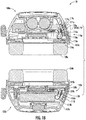
- FIG. 1A-1C show a hearing protection device 10 according to an embodiment described herein.
- the hearing protection device 10 as illustrated in FIG. 1A includes a supporting band 105 connecting a first ear cup 100a to a second ear cup 100b.
- An ear cup 100a,b can comprise a structural cup lined with sound-dampening material (also known herein as an "ear pad") dimensioned and configured to engage a wearer's head about the wearer's ears such that the sound-dampening material sealably engages the wearer's head.
- the hearing protection device 10 can be configured to prevent at least some of the ambient noise to which the wearer would otherwise be exposed if not wearing the hearing protection device 10 from reaching the wearer's ears.
- each of the ear cups 100a,b of the hearing protection device 10 can further include a noise sensor assembly 110a,b.
- the first ear cup 110a and the second ear cup 100b can be similar to, a mirror image configurationally of, dissimilar to, or identical to one another.
- the ear cups 100a,b are hereinafter referred generally as an ear cup 100 and components thereof will be referred to as a noise sensor assembly 110, a removable securing collar 111, and the like, without identifying a particular ear cup.
- the noise sensor assembly 110 can be positioned anywhere on or near the external surface of the ear cup 100 such that ambient noise from nearby the wearer's ear, external to the ear cups can be measured using the noise sensor assembly 110.
- This noise exposure signal can then be used in active noise cancellation to generate a destructively interfering audio signal that is generated via a processor and memory in one or both ear cups ( e.g., on the main PCB of the ear cups) and output via the speakers shown in each ear cup.
- the noise exposure signal may additionally or alternatively be used to compare with a noise exposure signal from a microphone inside the ear cups to determine the drop in noise exposure between the exterior and interior of the ear cups ( e.g., to confirm that the hearing protection device is working properly and is properly sealed and worn on the user's head).
- the noise sensor assembly 110 can be positioned as close to the wearer's ear as possible, such as on an outer portion of the ear cup 100 near the sound-dampening material. Without wishing to be bound by any particular theory, placing the noise sensor assembly 110 on or in the ear cup 100 at a position sufficiently nearby the wearer's ear may increase the accuracy of the sensed noise relative to actual noise to which the wearer would be exposed were they not wearing the hearing protection device 10.
- the hearing protection device 10 can further include a removable securing collar 111 disposed about the noise sensor assembly 110 and configured to retain the noise sensor assembly 110 at or proximate an aperture of the ear cup 100.
- the removable securing collar 111 can be disposed to an outer surface of the hearing protection device 10 and can be configured to span an aperture defined through the outer surface of the hearing protection device 10. In some embodiments, the removable securing collar 111 can be configured to the noise sensor assembly 110 on, within, or partially within the hearing protection device 10. In some embodiments, the removable securing collar 111 can include an opening dimensioned and configured to transmit sound therethrough to the noise sensor assembly 110. In some embodiments, the hearing protection device 10 can further include an external dust protector disposed between the noise sensor assembly 110 and the removable securing collar 111.
- the ear cup 100 further includes a noise sensor assembly 110 comprising a housing 116 ( e.g., 116a, 116b) fixably disposed at or proximate the aperture and defining an axial bore 123a, 123b therethrough.
- the housing 116 has a proximal portion of the axial bore 123a, 123b that is defined in part by a slot or ledge (not shown) such that the proximal portion is configured to receive a microphone 118 or other such sensor.
- the housing 116 has a distal portion of the axial bore 123a, 123b having an inner diameter that is less than the inner diameter of the proximal portion.
- the distal portion of the housing 116 can be configured to receive ambient noise from the environment outside the ear cup 100 and communicate that ambient noise to the microphone 118 or other such sensor disposed and retained within the proximal portion (also known herein as a noise sensor receiving portion 125) of the housing 116.
- the microphone 118 or other such sensor disposed within the proximal portion of the housing 116 can be disposed on one of the sensor printed circuit boards 114a, 114d (sensor PCBs 114a, 114d) and may be connected to one or more flexible printed circuit boards 114b, 114e (flexible PCB 114b, 114e).
- the one or more flexible PCBs 114b, 114e can be operably coupled to one or more main PCBs 114c, 114f.
- the noise sensor assembly 110 can further include an internal dust protector 119 disposed between the microphone 118 and the housing 116 at the proximal end of the distal portion of the axial bore 123a, 123b ( e.g., disposed between the sensor PCB 114a or 114d and the ledge) such that the microphone 118 can be exposed to ambient noise communicated through the distal portion of the axial bore 123a, 123b of the housing 116 without being exposed or with only slight exposure to contaminants such as dust from the environment outside the ear cup 100.
- an internal dust protector 119 disposed between the microphone 118 and the housing 116 at the proximal end of the distal portion of the axial bore 123a, 123b (e.g., disposed between the sensor PCB 114a or 114d and the ledge) such that the microphone 118 can be exposed to ambient noise communicated through the distal portion of the axial bore 123a, 123b of the housing 116 without being exposed or with only slight exposure to contaminants such as dust from
- the ear cup 100 can further include the removable securing collar 111 disposed at or proximate the aperture defined through one or more components of a casing of the ear cup 100 in such a way as to secure the noise sensor assembly 110 within the ear cup 100 and as a way to access the noise sensor assembly 110 without disassembling the whole ear cup 100.
- the casing can comprise one or more of a first external casing portion 117, a second external casing portion 121, an insert catch 115 coupled to one or more of the first external casing portions 117, 121, and a contacting lip 112 coupled to the insert catch 115.
- the term “external casing” or “external casing 117” is used to refer to any one or any combination of these or similar elements configured to define or partly define the aperture through which the microphone 118 can be in acoustic communication with the environment outside the ear cup 100.
- the hearing protection device 10 may be assembled at least in part by gluing or otherwise permanently adhering the ear pad 120a,b to the inside of the ear cup 100a,b, which can make it difficult to access the noise sensor assembly 110 by way of an inner surface 122a,b of the ear cup 100a,b.
- the durability and air tightness of the ear cup 100 may be compromised if the ear cup 100 is opened along manufacturing lines, e.g., at a seam formed between the first and second portions of the external casing 117, 121 of the ear cup 100.
- the removable securing collar 111 can define an opening through a portion, such as the center, of the removable securing collar 111, by which the noise sensor assembly 110 can be accessed without significant disassembly of the ear cup 100 and without compromising the hearing protection characteristics of the hearing protection device 10.
- the removable sealing collar 111 can further engage with the inset catch 115 of the external casing 117.
- the external casing 117 may be configured to carry or define the contacting lip 112 either as an integral piece or a separately inserted element.
- the distal end of the housing 116 can be configured to rest on one or both of the inset catch 115 or the contacting lip 112 such that the removable securing collar 111 or a portion thereof can be fixedly inserted between the external dust protector 113 and the inset catch 115.
- the external surface of the removable securing collar 111 can be flush or substantially flush with the outside surface of the external casing 117 of the ear cup 100.
- the ambient noise from the environment outside the ear cup 100 can communicate through the opening of the removable securing collar 111, into the distal portion of the axial bore 123, and to the microphone 118 or other such noise sensor disposed within the proximal portion of the axial bore 123 of the housing 116.
- the ear cup 100 can further include an external dust protector 113 disposed within, on, or about the aperture of the external casing 117 of the ear cup 100, between the distal end of the housing 116 and the removable securing collar 111.
- the internal dust protector 119 and/or the external dust protector 113 can prevent contaminants such as dust and other debris common to construction sites and other similar environments from reaching the microphone 118 and other electronics and circuitry within the ear cup 100 while also preventing the axial bore 123 from becoming clogged and impairing the performance of the microphone 118.
- the ear cups 100a,b can further include ear pads 120a,b dimensioned and configured to be sealably disposed to a wearer's head about a wearer's ear.
- the ear pad 120 can include or be made from a cushioning material, such as a deformable foam or rubber material such that the ear pad 120 has a noise dampening effect for the wearer when properly wearing the hearing protection device 10.
- the ear pad 120 can serve a similar purpose as the internal dust protector 119 and/or the external dust protector 113, which is to at least reduce and possibly prevent the communication of dust and other contaminants into the ear cup 100, when properly worn by the wearer.
- an interior space defined within the ear cup 100 by at least the ear pad 120, the external casing 117 of the ear cup 100, the housing 116 disposed at or proximate the aperture of the external casing 117 of the ear cup 100, and the microphone 118, sensor PCB 114a, or other such sensor element disposed within the proximal portion of the axial bore 123 of the housing 116, can be airtight or substantially airtight when properly worn by the wearer to provide effective noise reduction for the wearer.
- the distal portion of the axial bore 123 of the housing 116 can be configured and dimensioned such that a noise sensor calibration tool comprising a calibration tube can be securely fixed within the axial bore 123 for microphone 118 calibration by removing the removable securing collar 111, removing the external dust protector 113, and slidably disposing the noise sensor calibration tool into the axial bore 123 via a distal opening of the axial bore 123 of the housing 116.
- securely fixing the noise sensor calibration tool or the calibration tube within the axial bore 123 of the housing 116 for calibration of the microphone 118 or other such noise sensor can help prevent or reduce ambient noise from the environment outside the ear cup 100 being detected by the microphone 118 during calibration and that a calibrating noise emitted by the noise sensor calibration tool during in situ calibration of the microphone 118 or other such noise sensor remains substantially within the axial bore 123 of the housing 116 and is not emitted to the interior space of the ear cup 100 or the environment outside the ear cup 100.
- the microphone 118 or other such noise sensor can be calibrated in place without significant disassembly of the hearing protection device 10 and such that the space around the microphone 118 is substantially airtight during calibration, increasing the accuracy of calibration.
- the external dust protector 113 may be removed for calibration, while the internal dust protector 119 is left in place.
- the housing 116 In some embodiments, such as when a hearing protection system and associated apparatus benefit from being airtight, during use and/or during calibration, it was found to be helpful to dimension and configure the housing 116 to have or define a securing portion at the distal end of the housing 116 that has a narrower portion relative to the outer diameter of the main body of the housing 116 proximal the narrower portion of the housing 116 and a wider portion of the housing 116 distal the narrower portion of the housing 116.
- an outer diameter of the narrower portion of the housing 116 can be dimensioned and configured to correspond substantially with an inner diameter of the aperture of the external casing 117 of the ear cup 100 (or as applicable, a narrower opening in the external casing, such as the contacting lip 112 shown in FIG. 1C ) such that the housing 116 can be inserted into the aperture of the external casing 117 and retained sealably in place when an outer surface of the narrower portion of the housing 116 abuts an inner surface or an inner edge at or proximate aperture of the external casing 117 to at least partially seal the aperture.
- the housing 116 can be at least somewhat deformable such that the wider portion of the housing 116 can be fit through the aperture of the external casing 117 of the ear cup 100 during assembly of the ear cup.
- the ear cup 100 can be assembled, at least in part, by temporarily deforming the wider portion of the housing 116 at or near the distal end of the housing 116 and fitting the wider portion of the housing 116 through the aperture of the external casing 117 of the ear cup 100 from the inside of the ear cup 100, soldering or otherwise electrically coupling the microphone 118 to the sensor PCB 114a, and disposing the microphone 118 through an opening at the proximal end of the housing 116 until the sensor PCB 114a comes to rest on the ledge or slot defined at a transition point where the proximal portion of the axial bore 123 of the housing 116 narrows to define a proximal end of the distal portion of the axial bore 123.
- the housing 116 can be a monolithic structure in order to facilitate the airtight nature of the interior region of the ear cup 100 during use of the hearing protection device 10 and the airtight nature of the axial bore 123 of the housing 116 during calibration of the microphone 118.
- the external casing 117 of the hearing protection device 10 can include a first portion 121 and a second portion 124. In some embodiments, the first portion 121 and/or the second portion 124 can be configured to at least partially define the aperture. In some embodiments, the external casing 117 can be configured to sealably retain the removable securing collar 111 in the aperture.
- the second portion 124 of the external casing 117 can be configured to be sealed to the first portion 121 such that at least a portion of the first portion 121 of the external casing 117, the second portion 124 of the external casing 117, the removable securing collar 111, the ear pad 120, and/or the housing 116 define the inner space of the ear cup 110 of the hearing protection device 10.
- the housing 116 comprises an inner surface defining an axial bore 123.
- a distal end of the axial bore 123 of the housing 116 is configured to acoustically communicate with an external environment via the aperture defined in the external casing 117.
- the housing 116 defines a noise sensor receiving portion 125 comprising a slot 116r, a ridge 116u, and/or a ledge 116k configured to engage at least a portion of the noise sensor assembly 110, such as the sensor PCB 114a and/or the microphone 118.
- the proximal portion of the axial bore 123 can comprise or define the noise sensor receiving portion 125.
- the noise sensor receiving portion 125 can be defined as a portion of the axial bore 123 between the proximal portion and the distal portion.
- the slot 116r of the housing 116 is configured to retain the noise sensor 110, such that the microphone 118 is configured to receive acoustic signals from the axial bore 123, e.g., the distal end of the axial bore 123.
- the sensor PCB 114a in an instance in which the sensor PCB 114a is engaged with the housing 116, the sensor PCB 114a is sealed against the housing 116 and the sensor PCB 114a and the housing 116 seal the aperture defined by the external casing 117 of the ear cup 100.
- the housing 116 can be secured at or proximate the aperture of the external casing 117 and the microphone 118 and sensor PCB 114a can be secured within the noise sensor receiving portion 125 of the housing 116 such that ambient noise from outside the ear cup 100 can reach the microphone 118 by way of the axial bore 123 defined by the housing 116.
- the ear cup 100 can further include an interior region defined at least in part by the exterior casing 117 of the ear cup 100 and an ear pad 120 configured to contact a wearer's head about the wearer's ear.
- the housing 116 in conjunction with the microphone 118 and the ear pad 120, can be configured such that the interior region of the ear cup 110 can be airtight or substantially air tight when the wearer is wearing the hearing protection device.
- the ear cup 110 can further include a removable securing collar 111 configured to secure the housing 116 in place at or proximate the aperture of the external casing 117.
- the removable securing collar 111 can define an opening through the middle or substantially through the middle of the removable securing collar 111 such that ambient noise can travel through the opening of the removable securing collar 111, into the axial bore 123 of the housing 116, and reach the microphone 118.
- the ear cup 110 can further include an external dust protector 113 disposed between the distal end of the housing 116 and the removable securing collar 111.
- the external dust protector 113 can be configured to impede the communication of debris such as dust, dirt, moisture, and the like into the housing 116 without impeding the audible communication of ambient noise to the microphone 118 during use of the hearing protection device.
- the removable securing collar 111 and/or external dust protector 113 can be removed in order to access the axial bore 123 for in situ calibration of the microphone 118.
- the calibration tool having a sufficient form factor can be slidably inserted into the axial bore 123 of the housing 116 such that a calibrating sounds can be emitted nearby the microphone 118.
- the removable securing collar 111 may be engaged with the external casing 117 via one or more securing tabs or other interference fit structures, such that adhesives and permanent affixation elements are not required.
- the microphone 118 it can be helpful or even necessary to form an airtight or substantially airtight seal between the calibration tool and the inner surface of the housing 116 such that the microphone 118 is not exposed to ambient noise in addition to the calibrating sound during calibration and so that the full measure of the calibrating sound reaches the microphone 118.
- the housing 116 can be configured to have suitable mechanical properties such that the microphone 118 is securely retained within the housing 116, while the housing 116 provides some amount of attenuation of vibrations caused by movement of the hearing protection device 10 by the wearer, by sound waves from nearby sound sources such as speakers and/or the environment outside the ear cup 100, and the like.
- the housing 116 may be made of rubber or a rubber-like material.
- some benefits of the invention include a reduction in number and complexity of components required for noise sensing in the hearing protection device leading to a reduction in manufacturing cost and complexity, a reduction in probability of component failure, and a reduced occupied volume leading to a smaller possible ear cup 100 profile. Also, since the microphone 118 can be calibrated, the accuracy of noise detection will be improved. Furthermore, since the microphone 118 can be calibrated without significant disassembly of the ear cup 100, the cost, time, and complexity of calibration of the microphone 118 are reduced.
- the in situ calibration of the microphone 118 is more effective, meaning the accuracy of the calibrated microphone 118 for this hearing protection device 10 is greater than microphones of conventional hearing protection devices that are not able to be calibrated at all, not able to be calibrated after assembly of the hearing protection device, and/or can only be calibrated in less than airtight environments.
- the microphone 118 which can be any suitable type of microphone such as a microelectro-mechanical systems- (MEMS)-based microphone or the like, can be mounted on, fixed to, electrically coupled to, soldered to, and/or otherwise coupled to the sensor PCB 114a.
- the sensor PCB 114a can be particularly dimensioned and configured such that a portion of the sensor PCB 114a can be retained, with the microphone 118, within the noise sensor receiving portion 125 of the housing 116.
- the sensor PCB 114a can have any suitable form factor such that the sensor PCB 114a can sealably abut a surface of the noise sensor receiving portion 125 of the housing 116.
- the sensor PCB 114a can have a form factor that is substantially flat, planar, smooth, round, square, rectangular, quadrilateral, quadrangular, tubular, ellipsoidal, homogenous, even, symmetrical, asymmetrical, or the like.
- the sensor PCB 114a or a portion thereof can be at least partially flexible.
- the ear cup 100 can further comprise a main PCB 114c electrically connected via a flexible PCB 114b to the sensor PCB 114a, the sensor PCB 114a configured to be electrically coupled to the microphone 118.
- the main PCB 114c may comprise a processor and memory for performing the signal processing of at least a portion of the hearing protection device, such as the examples described herein.
- the slot of the noise sensor receiving portion 125 of the housing 116 can define a volume having extents and dimensions that can be substantially inversely similar to the dimensions of the sensor PCB 114a such that the sensor PCB 114a can be securely disposed within the receiving portion of the housing 116 without adhesive or fasteners or otherwise securing the sensor PCB 114a within the housing other than by the relative dimensions of either.
- the noise sensor receiving portion 125 of the housing 116 can be configured and dimensioned to releasably retain the noise sensor, comprising the sensor PCB 114a and the microphone 118, within the noise sensor receiving portion 125 of the housing 116.
- the particular dimensions of the noise sensor receiving portion 125 of the housing 116 can be particularly configured to retain the sensor assembly, comprising the sensor PCB 114a and the microphone 118, within the noise sensor receiving portion 125 of the housing 116, thereby forming an airtight seal between at least one of the sensor PCB 114a and the microphone 118, and the housing 116.
- noise sensor assembly 110 when the noise sensor assembly 110 is properly assembled, air and noise from the environment outside the ear cup 100 can be communicated into the distal portion of the axial bore 123 of the housing 116 and to the microphone 118 and/or the sensor PCB 114a, but is prevented from communicating through the axial bore 123 past the microphone 118 and/or the sensor PCB 114a.
- noise from the environment outside the ear cup 100 can be freely measured using the noise sensor assembly 110 but the interior space of the ear cup 100, including the proximal portion of the axial bore 123 of the housing 116 is not substantially exposed to the noise, air, contaminants, and the like from the environment outside the ear cup 100 due to the airtight seal and noise reduction technologies described herein.
- the exterior casing 117 of the ear cup 100 and the removable securing collar 111 can comprise or be formed from any suitably durable yet light material, such as a plastic material like acrylonitrile butadiene styrene (ABS) or the like.
- the internal dust protector 119 can comprise or be formed from any suitable filtering material, such as Gore filtration material PE 120205 and other suitable ingress protection (IP) filter materials.
- the internal dust protector 119 can be further configured to prevent flux of water between the distal portion of the axial bore 123 of the housing 116 and the noise sensor assembly disposed in the noise sensor receiving portion 125 proximate the distal portion of the axial bore 123 of the housing 116, thus preventing moisture damage to the sensor PCB 114a and/or the microphone 118.
- the housing 116 can comprise or be formed from any suitably durable and yet deformable material, such as a synthetic rubber like ethylene propylene diene monomer (EPDM) rubber and the like.
- the external dust protector 113 can comprise or be formed from any suitable dust filtering material such as a foam, a mesh, a woven fiber, and the like.
- the ear cup 100 can further comprise an internal microphone 140 configured as a noise sensor to sense noise exposure within the inner space of the ear cup 100.
- the internal microphone 140 can be configured to measure noise from outside the ear cup 100 that is communicated into the inner space of the ear cup 100.
- the hearing protection device 10 can be configured such that the noise sensor assembly 110, the internal microphone 140, other suitable computing devices and/or circuitry, or other devices can be caused to transmit and/or store noise exposure data during use of the hearing protection device 10.
- a signal indicative of a magnitude of noise exposure can be transmitted from the microphone 118 and/or the internal microphone 140 to the main PCB 114c or other suitable computing devices or circuitry, a memory device, or the like.
- the magnitude of noise exposure measured by the microphone 118 can be compared to the magnitude of noise exposure measured by the internal microphone 140 to determine the effectiveness of the active and/or passive noise dampening capabilities of the hearing protection device 10, to identify improper use by the wearer such as when an ear cup 100 is not properly fitted against the wearer's head about the wearer's ears, and to identify when a noise sensor is in need of calibration or is malfunctioning.
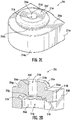
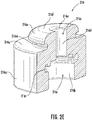
- an ear cup for a hearing protection device (e.g., 10) can include a housing 216 as illustrated, according to an embodiment of the present disclosure.
- the features of the housing 216 shown in FIGS. 2A-2E may be included in the depicted housing 116 in FIGS. 1B-1C , and vice versa.
- the housing 216 is dimensioned and configured to be fixably disposed at or proximate an aperture defined through an external casing of the ear cup.
- the housing 216 defines an axial bore 216c therethrough between a proximal end 216g and a distal end ( i.e., 216f).
- the housing 116 has a proximal portion 216b of the axial bore 216c that is defined in part by a slot 216r and/or ledge 216k such that the proximal portion 216b is configured to receive a microphone ( e.g., 118) or other such sensor.
- the housing 216 can comprise a distal portion 216d of the axial bore 216c having an inner diameter that is less than the inner diameter of the proximal portion 216b.
- the ledge 216k can be defined by the portion of the axial bore 216c at the transition between the narrower distal portion 216d and the wider proximal portion 216b.
- the ledge 216k can be formed as a surface facing the proximal end 216g of the housing 216 and configured to engage the microphone PCB.
- the proximal portion 216b of the axial bore 216c can have a wider inner diameter at a transition point 216s from the distal portion 216d to the proximal portion 216b, the transition point 216s at least partly defining the ledge 216k.
- the inner diameter of the proximal portion 216b can be smaller at one or more points proximal the transition point 216s such that the slot 216r is formed.
- the slot 216r can be the portion of the proximal portion 216b or of the axial bore 216c in general that has the largest inner diameter such that the noise sensor can be retained in the slot 216r against movement in an axial direction by a reduced inner diameter both distal the slot and proximal the slot 216r.
- a narrower region e.g.
- proximal portion 216b of the axial bore 216c proximal the slot 216r can be at least partially open in a radial direction (e.g., a cutout in the side wall of the portion of the axial bore proximal to the slot), meaning, in some embodiments, a region of an outer wall ( e.g., 216a, 216q, 216h) of the housing 216 aligned with the narrower region of the proximal portion 216b may extend only part of the way around the axial bore 216c, such that one or more components of the noise sensor can extend out radially from the proximal portion 216b of the axial bore 216c at a location proximal the slot 216r.
- a radial direction e.g., a cutout in the side wall of the portion of the axial bore proximal to the slot
- the distal portion 216d of the housing 216 can be configured to receive ambient noise from the environment outside the ear cup and communicate that ambient noise to the microphone or other such sensor disposed and retained within the proximal portion 216b (or a portion thereof known herein as a noise sensor receiving portion 216r) of the housing 216.
- the microphone or other such sensor disposed within the proximal portion of the housing 216 can be connected to a printed circuit board (PCB, e.g., the PCB 114a) having a suitable form factor such that at least a portion of the PCB is retained within a noise sensor receiving portion 216j of the axial bore 216c of the housing 216.
- PCB printed circuit board
- the proximal portion 216b can comprise or define the noise sensor receiving portion 216j.
- the noise sensor receiving portion 216j can be defined as a portion of the axial bore 216c within the proximal portion 216b and adjacent the distal portion 216d.
- the one or more PCBs can include a microphone PCB 114a operably coupled to the microphone 118 or other such sensor, a flexible PCB 114b operably connected to the microphone PCB 114a, and a main PCB 114c to which the flexible PCB 114b is operably coupled.
- the distal portion 216d of the axial bore 216c of the housing 216 can be configured and dimensioned such that a noise sensor calibration tool can be securely fixed within the axial bore 216c for microphone calibration slidably disposing the noise sensor calibration tool through the distal end of the axial bore 216d and towards the proximal portion 216b of the housing 216.
- securely fixing the noise sensor calibration tool within the axial bore 216c of the housing 216 for calibration of the microphone or other such noise sensor can help prevent or reduce ambient noise from the environment outside the ear cup being detected by the microphone during calibration and can prevent or reduce emission of a calibrating noise emitted by the noise sensor calibration tool during in situ calibration of the microphone or other such noise sensor to outside the housing 216, such as to the interior space of the ear cup or the environment outside the ear cup.
- the microphone or other such noise sensor can be calibrated in place without significant disassembly of the hearing protection device and such that the space around the microphone is substantially airtight during calibration, increasing the accuracy of calibration.
- the housing 216 it was found to be helpful to dimension and configure the housing 216 to have or define a securing portion 216n at or near the distal end of the housing 216, the securing portion 216n comprising a narrower portion 216m relative to the outer diameter of the main body of the housing 216 proximal the narrower portion of the securing portion 216n and a wider portion 216f of the securing portion 216n distal the narrower portion 216m of the securing portion 216n.
- an outer diameter of the narrower portion 216m of the securing portion 216n can be dimensioned and configured to correspond substantially with an inner diameter of the aperture of the external casing of the ear cup or one or more intermediate components (e.g., the contacting lip 112) such that the housing 216 can be inserted into the aperture of the external casing and retained sealably in place when an outer surface of the narrower portion 216m of the securing portion 216n abuts an inner surface or an inner edge of the aperture of the external casing or other intermediate component at the aperture.
- the housing 216 can be at least somewhat deformable such that the wider portion 216f of the securing portion 216n can be fit through the aperture of the external casing of the ear cup during assembly of the ear cup.
- the ear cup can be assembled, at least in part, by temporarily deforming the wider portion 216f of the securing portion 216n at or near the distal end of the housing 216 and fitting the distal portion 216f of the housing 216 through the aperture of the external casing of the ear cup from the inside of the ear cup, soldering or otherwise electrically coupling the microphone to the PCB, and disposing the microphone and a portion of the PCB into the proximal end of the axial bore 216c of the housing 116 until the microphone and/or the portion of the PCB come(s) to rest in the slot 216r and/or on the ledge 216k, the ledge 216k defined as an internal surface perpendicular to the axial bore 216c and positioned at
- the ledge 216k can comprise a ridge 216u raised above the surface of the ledge 216k in a proximal direction and configured to sealably engage at least one of the sensor PCB 114a and the microphone 118.
- the housing 216 can be a monolithic structure in order to facilitate the airtight nature of the interior region of the ear cup during use of the hearing protection device and the airtight nature of the axial bore of the housing 216 during calibration of the microphone.
- the distal portion 216d of the axial bore 216c of the housing 216 is configured to acoustically communicate with an external environment via the aperture defined in the external casing of the ear cup.
- the housing 216 can define a noise sensor receiving portion 216j comprising the slot 216r, the ledge 216k and the ridge 216u, the slot 216r, the ledge 216k, and/or the ridge 216u configured to engage the PCB and/or the microphone of the noise sensor assembly.
- the slot 216r and/or the ledge 216k of the housing 216 can be configured to retain the noise sensor, such that the microphone faces the axial bore, e.g., the distal end of the axial bore.
- the noise sensor in an instance in which the noise sensor is engaged with the housing 216, can be sealed or substantially sealed against the housing 216 and the noise sensor and the housing 216 can be configured to seal the aperture defined by the external casing of the ear cup.
- the housing 216 can be secured at or proximate the aperture of the external casing and the microphone and/or PCB can be secured within the noise sensor receiving portion 216j of the housing 216 such that ambient noise from outside the ear cup can reach the microphone by way of the distal portion 216d of the axial bore 216c.
- the distal portion 216d of the axial bore 216c of the housing 216 can be accessible for in situ calibration of the microphone either during normal use of the hearing protection device or after only removing minimal components, such as only the removable sealing collar or only the removable sealing collar and an external dust protector.
- a calibration tool having a sufficient form factor can be slidably inserted into the axial bore 216c of the housing 216 such that a calibrating sound can be emitted nearby the microphone.
- an airtight or substantially airtight seal with the inner surface of the distal portion 216d of the axial bore 216c such that the microphone is not exposed to ambient noise in addition to the calibrating sound during calibration and so that the full magnitude of the calibrating sound reaches the microphone.
- the housing 216 can be configured to have suitable mechanical properties such that the microphone is securely retained within the housing 216, but that the housing 216 provides some amount of attenuation of vibrations caused by movement of the hearing protection device by the wearer, by sound waves from nearby sound sources such as speakers and/or the environment outside the ear cup, and the like.
- the housing 216 is a monolithic structure formed as a single piece or component, some benefits of the invention include a reduction in number and complexity of components required for noise sensing in the hearing protection device leading to a reduction in manufacturing cost and complexity, a reduction in probability of component failure, and a reduced occupied volume leading to a smaller possible ear cup profile.
- the microphone can be calibrated, the accuracy of noise detection will be improved. Furthermore, since the microphone can be calibrated without significant disassembly of the ear cup, the cost, time, and complexity of calibration of the microphone are reduced. Furthermore, since the axial bore of the housing 216 is dimensioned and configured to slidably and sealably receive standard calibration tools during calibration of the microphone, the in situ calibration of the microphone is more effective, meaning the accuracy of the calibrated microphone for this hearing protection device is greater than microphones of conventional hearing protection devices that are not able to be calibrated at all, not able to be calibrated after assembly of the hearing protection device, and/or can only be calibrated in less than airtight environments.
- the housing 216 comprises a rounded exterior surface 216q, one or more flat exterior surfaces 216a, 216h on the outside of the housing 216 oriented parallel to the axial bore 216c, and one or more other flat exterior surfaces 216g, 216p, 216i on the outside of the housing 216 oriented perpendicular to the axial bore 216c.
- the rounded exterior surface 216q and/or the one or more flat exterior surfaces 216a, 216h may be configured to abut a portion or component of the ear cup.
- the rounded exterior surface 216q and/or the one or more flat exterior surfaces 216a, 216h may be configured to abut a portion or component of the ear cup such that the housing 216 is prevented from rotation relative to an orientation of the rest of the ear cup.
- the proximal portion 216b of the axial bore 216c of the housing 216 may comprise or be adjoining one or more flat interior surfaces 216f such that a cut-out is defined between the one or more flat interior surfaces 216 and through a portion of a flat exterior surface 216h or a rounded exterior surface 216q.
- the PCB may be disposed within the noise sensor receiving portion 216j of the housing 216 along with the microphone, while another portion of the PCB extends from the axial bore 216c, through the cut-out portion of the flat exterior surface 216h or the rounded exterior surface 216q of the housing 216, and into the interior space of the ear cup such that the PCB can be electrically coupled to other electronic components such as another PCB, a microprocessor or the like.
- the portions of the housing surrounding the cut-out may define a horseshoe shape to facilitate insertion of the PCB by separating or pulling apart the distal ends of the horseshoe shape ( e.g., with pliers) to allow the microphone PCB to insert into the slot.
- a noise sensor assembly 210 comprises at least a microphone 218 and a sensor printed circuit board (PCB) 214a.
- the sensor PCB 214a can be electrically and/or operably coupled to the microphone 218.
- the sensor PCB 214a can be electrically and/or operably coupled to a flexible PCB 214b and the flexible PCB 214b can be operably coupled to a main PCB 214c.
- the noise sensor assembly 210 or a portion thereof can be disposed within a portion of the housing 216, such as the noise sensor receiving portion 216j.
- the microphone 218 can be any suitable type of microphone such as a microelectro-mechanical systems- (MEMS)-based microphone or the like, can be mounted on, fixed to, electrically coupled to, soldered to, and/or otherwise coupled to the sensor PCB 214a.
- MEMS microelectro-mechanical systems-
- the sensor PCB 214a can be particularly dimensioned and configured such that at least a portion of the sensor PCB 214a can be retained, with the microphone 218, within the noise sensor receiving portion 216j of the housing 216.
- the sensor PCB 214a can have any suitable form factor such that the sensor PCB 214a can sealably abut a surface of the receiving portion of the housing 216.
- the sensor PCB 214a can have a form factor that is substantially flat, planar, smooth, round, square, rectangular, quadrilateral, quadrangular, tubular, ellipsoidal, homogenous, even, symmetrical, asymmetrical, or the like.
- the sensor PCB 214a forms a substantially circular shape corresponding to the shape of the slot 216r shown in FIG. 2A-2E .
- the electrical components mounted to the sensor PCB 214a may be offset from the edges such that the housing 216 can grip the sensor PCB 214a.
- the noise sensor receiving portion 216j of the housing 216 can define a volume having extents and dimensions that can be substantially inversely similar to the dimensions of the sensor PCB 214a such that at least a portion of the sensor PCB 214a can be securely disposed within the receiving portion of the housing 216 without adhesive or fasteners or otherwise securing the sensor PCB 214a within the housing 214 other than by the relative dimensions of either.
- the noise sensor receiving portion 216j of the housing 216 can be configured and dimensioned to releasably retain the noise sensor, comprising the sensor PCB 214a and the microphone 218, within the noise sensor receiving portion 216j of the housing 216 in a similar manner.
- the particular dimensions of the noise sensor receiving portion 216j of the housing 216 can be particularly configured to retain the sensor assembly, comprising the sensor PCB 214a and the microphone 218, within the noise sensor receiving portion 216j of the housing 216, thereby forming an airtight seal between at least one of the sensor PCB 214a and the microphone 218, and the housing 218.
- the sensor PCB 214a can have any suitable form factor such that the sensor PCB 214a can sealably abut a surface of the receiving portion of the housing 216.
- the sensor PCB 214a, the flexible PCB 214b and/or the main PCB 214c can have a form factor that is substantially flat, planar, smooth, round, square, rectangular, quadrilateral, quadrangular, tubular, ellipsoidal, homogenous, even, symmetrical, asymmetrical, or the like.
- the sensor PCB 214a or a portion thereof can be at least partially flexible.
- the sensor PCB 214a can be electrically connected via the flexible PCB 216b to the main PCB 214c or other such computing device or circuitry, and the sensor PCB 214a can be electrically connected to the microphone 218.
- the noise sensor assembly 210 when the noise sensor assembly 210 is properly assembled, air and noise from the environment outside the ear cup can be communicated into the distal portion 216d of the axial bore 216c of the housing 216 and to the microphone 218 and/or the sensor PCB 214a, but is prevented from communicating through the axial bore 216c to locations proximal the microphone 218 and/or the sensor PCB 214a.
- noise from the environment outside the ear cup can be freely measured using the noise sensor assembly 210 but the interior space of the ear cup, including the proximal portion 216b of the axial bore 216c of the housing 216 is substantially not exposed to the noise, air, contaminants, and the like from the environment outside the ear cup based upon the air tightness and noise reduction techniques described herein.
- the microphone 218 can comprise a silicon wafer having a movable membrane and a fixed back plate over a cavity in the base wafer.
- the sensor back plate can have a stiff perforated structure.
- the microphone 218 can be a microelectro-mechanical system (MEMS) microphone.
- MEMS microelectro-mechanical system
- the ASIC can use a charge pump to place a fixed charge on the movable membrane of the microphone 218, and the ASIC can then measure voltage variations caused by capacitance changes related to movements of the movable membrane relative to the fixed back plate.
- the microphone 218 can comprise the above-mentioned components according to some embodiments, the microphone 218 can comprise any suitable combination of components such that noise exposure can be sensed.
- the sensor PCB 214a and/or the flexible PCB 214b can comprise an insulated substrate supporting a plurality of electrical components and conductive tracks, and can be configured to communicate electrical signals and data between computing devices and other related circuitry.
- the sensor PCB 214a can be configured to receive the electrical signal from the microphone 218, for example from the ASIC, the electrical signal indicative of the movement of the movable membrane of the microphone 218 in response to a magnitude of air movements related to a magnitude of noise exposure.
- the sensor PCB 214a can comprise the above-mentioned components according to some embodiments, the sensor PCB 214a can comprise any suitable combination of components such that a signal received from the microphone 218 can be transmitted and/or interpreted relative to a magnitude of noise exposure sensed by the microphone 218.
Landscapes
- Health & Medical Sciences (AREA)
- Engineering & Computer Science (AREA)
- Acoustics & Sound (AREA)
- Physics & Mathematics (AREA)
- Otolaryngology (AREA)
- Life Sciences & Earth Sciences (AREA)
- Signal Processing (AREA)
- General Health & Medical Sciences (AREA)
- Public Health (AREA)
- Heart & Thoracic Surgery (AREA)
- Vascular Medicine (AREA)
- Animal Behavior & Ethology (AREA)
- Biomedical Technology (AREA)
- Psychology (AREA)
- Veterinary Medicine (AREA)
- Biophysics (AREA)
- Manufacturing & Machinery (AREA)
- Details Of Audible-Bandwidth Transducers (AREA)
- Soundproofing, Sound Blocking, And Sound Damping (AREA)
- Headphones And Earphones (AREA)
Description
- In the field of hearing protection, hearing protection devices such as earmuffs are often used to protect a wearer's ears from excessive noise exposure. Such hearing protection devices often provide a passive and/or active noise dampening or noise cancellation effect for the wearer, often in an effort to reduce the total noise exposure for a wearer to below a regulated or suggested acute or chronic exposure limit. In such devices, one or more noise sensors can be placed in or about the hearing protection device. However, such noise sensors are often susceptible to damage from exposure to dust and other contaminants, often measure noise exposure in a manner that is not true to the wearer's actual exposure, are costly to manufacture, require significant space within the hearing device, and often cannot be calibrated reliably and/or without substantial disassembly of the hearing protection device. Through applied effort, ingenuity, and innovation, many of these identified problems have been solved by developing solutions that are included in embodiments of the present disclosure, many examples of which are described in detail herein.
-
WO 2006/118516 discloses an ear cup with a microphone apparatus which comprises an inner cup portion, for forming a noise damping space, and an outer cup portion for forming a space for accommodating electronics and/or a current source. The inner cup portion and the outer cup portion are separated by a partition. The inner cup portion has a pocket and two opposingly located recesses in which a bracket for a microphone is disposed. Over the microphone, a windshield is provided, this protecting the microphone from being damaged and also damping wind noise. The windshield has an outer configuration that may be seen as a continuation of the outer cup portion, in order to prevent turbulence in the region of the windshield. The windshield is produced from a porous material, which is surrounded by a mounting frame having nap catches for engagement in snap catches;US 2010/303270 discloses a hearing protection system with talk-through having a pair of rigid earcups enclosing a microphone, amplifier and speaker. A concha simulator, having a volume simulating that of the concha of a human ear, is acoustically coupled to the microphone, and also to the outside through an opening in the earcup. By coupling the microphone to the concha simulator, instead of directly to the outside, the acoustic response of the talk-through more accurately represents the hearing of a user. - The present invention is defined by the appended claims.
- One aspect of the invention provides a noise sensor assembly for a hearing protection device, the noise sensor assembly comprising: a printed circuit board (PCB); a noise sensor comprising a microphone mounted on the PCB and electrically coupled to the PCB; a housing dimensioned and configured to be fixably disposed at or proximate an aperture defined in an outer surface of an external casing of the hearing protection device, wherein the housing comprises an inner surface defining an axial bore, wherein a distal end of the axial bore is configured to acoustically communicate with an external environment via the aperture, wherein the housing defines a noise sensor receiving portion comprising a slot configured to engage the PCB (114) on which the microphone is mounted and to which the microphone is electrically coupled, wherein the slot of the housing is configured to retain the microphone, such that the microphone faces the axial bore, wherein in an instance in which the noise sensor is engaged with the housing, the noise sensor is sealed against the housing. In some embodiments, the axial bore of the housing is dimensioned and configured to slidably receive a calibration tool to form an airtight seal with the inner surface of the housing. In some embodiments, the housing can further define a securing portion at a distal end, the securing portion adapted to contact and secure the housing with respect to a portion of the outer surface of the hearing protection device. In some embodiments, the noise sensor assembly can further comprise an internal dust protector disposed between the noise sensor receiving portion of the housing and the noise sensor, and wherein the internal dust protector is disposed between the microphone and the axial bore. In some embodiments, the housing comprises at least one of a vibration attenuation material and a noise dampening material. In some embodiments, in an instance in which the noise sensor is engaged with the housing, the noise sensor is retained within the noise senor receiving portion and abuts the slot.
- Another aspect of the invention provides an ear cup for a hearing protection device, the ear cup comprising: an external casing defining an aperture; a printed circuit board (PCB); a noise sensor comprising a microphone mounted on the PCB and electrically coupled to the PCB; and a housing fixably disposed at or proximate the aperture defined by the external casing, wherein the housing comprises an inner surface defining an axial bore, wherein a distal end of the axial bore is configured to acoustically communicate with an external environment via the aperture, wherein the housing defines a noise sensor receiving portion comprising a slot configured to engage the PCB (114) on which the microphone is mounted and to which the microphone is electrically coupled, wherein the slot of the housing is configured to retain the microphone, such that the microphone faces the axial bore, wherein in an instance in which the noise sensor is engaged with the housing, the noise sensor is sealed against the housing, and the noise sensor and the housing seal the aperture defined by the external casing. In some embodiments, the ear cup can further comprise a removable securing collar. In some embodiments, the external casing comprises a first portion and a second portion, the second portion defining the aperture configured to sealably retain the removable securing collar, the second portion configured to sealably engage the first portion such that the first portion, the second portion, and the removable securing collar seal the aperture in the external casing. In some embodiments, the noise sensor receiving portion of the axial bore has a first inner diameter and the distal end portion of the axial bore has a second inner diameter less than the first inner diameter. In some embodiments, the ear cup can further comprise a removable sealing collar configured to sealably retain the housing at or proximate the aperture defined by the external casing, the removable securing collar comprising an opening such that the distal end of the axial bore of the housing is configured to acoustically communicate with the external environment via the aperture of the external casing and the opening of the removable sealing collar. In some embodiments, the ear cup can further comprise a removable sealing collar configured to be retained by the aperture, wherein the axial bore of the housing is configured such that when the removable securing collar is removed and the calibration tool is slidably inserted into the axial bore of the housing, the calibration tool forms an airtight seal with an inner surface of the axial bore of the housing. In some embodiments, the ear cup can further comprise an external dust protector disposed between the housing and the removable securing collar. In some embodiments, the housing further comprises a securing portion disposed about the axial bore, the securing portion comprising a first securing portion at a distal end of the housing having a first outer diameter and a second securing portion proximal of the first securing portion, the second securing portion have a second outer diameter less than the first outer diameter, the first securing portion and the second securing portion defining a flange and recess configured to secure the housing relative to the external casing. In some embodiments, in an instance in which the noise sensor is engaged with the housing and the housing is sealably disposed directly or indirectly at or proximate the aperture of the external casing of the ear cup, and the ear cup is sealably engaged to a wearer's head about the wearer's ear, an internal volume of the ear cup is substantially airtight.
- Yet another aspect of the invention provides a method for calibrating the noise sensor of the hearing protection device set out above, the method comprising disposing a calibration tool through the aperture via the axial bore of the housing such that an interior of the calibration tool and the microphone are part of a closed system; emitting, by the calibration tool, a calibrating sound having predetermined sound characteristics; receiving, using the microphone, one or more detected sound characteristics of the calibrating sound; and in an instance in which a comparison of the one or more detected sound characteristics of the calibrating sound received by the microphone and the sound characteristics of the calibrating sound is indicative of a calibration error, calibrating the noise sensor relative to the calibrating sound.
- The accompanying drawings, which constitute a part of the description, illustrate embodiments of the present invention and, together with the description thereof, serve to explain the principles of the present invention.
-
FIG. 1A shows a perspective view of a hearing protection device, according to an embodiment of the present invention. -
FIG. 1B shows a cut-away view of the hearing protection device ofFIG. 1A , according to an embodiment of the present invention. -
FIG. 1C shows a detail from the cut-away view of the hearing protection device shown inFIG. 1B , according to an embodiment of the present invention. -
FIGS. 2A-2E show various views of a housing for noise sensor of a hearing protection device, according to an embodiment of the present invention. -
FIGS. 3A and 3B show various views of a noise sensor for a hearing protection device, according to an embodiment of the present invention. - In the field of hearing protection, hearing protection devices such as earmuffs may be used to protect a wearer's ears from excessive noise exposure. Such hearing protection devices may provide a passive and/or active noise dampening or noise cancellation effect for the wearer, often in an effort to reduce the total noise exposure for a wearer to below a regulated or suggested acute or chronic exposure limit. For instance, an 8 hour maximum daily exposure time may be associated with a noise exposure level of about 85 decibels (dBA), while a person may be limited to 2 hours of exposure time per day for a noise exposure level of 91 dBA, 30 minutes for a noise exposure level of 97 dBA, and seven minutes for a noise exposure level of 103 dBA. By wearing such hearing protection devices, a wearer is able to reduce their noise exposure level, thereby lengthening the maximum daily exposure time such that the wearer can, for example, remain in a higher ambient noise working environment for a longer period of time under such exposure limit regulations. In some embodiments discussed herein, to perform active noise cancellation and/or verify that the hearing protection device is effectively preventing noise exposure during use, one or more noise sensors can be placed in or about the hearing protection device (e.g., on or in an ear cup of a pair of earmuffs). Since these noise sensors must be quite small while also being effective, microelectro-mechanical system (MEMS) microphones can be used as the noise sensors. Embodiments of the present disclosure facilitate such noise sensors, and may reduce exposure to dust and other contaminants, may measure noise exposure in a manner that is true to the wearer's actual exposure, and may be calibrated reliably and/or without substantial disassembly of the hearing protection device while having a small footprint in the hearing protection device and being cost effective.
- Microphones, such as MEMS microphones, for use as a noise exposure sensor in ear muffs or other such hearing protection can often comprise a vibrating diaphragm and a back electrode, forming a capacitor integrated on a silicon wafer, which thereby realizes the acoustic-electric conversion. Such a capacitive microphone may be provided with through holes on its back electrode in order to balance the pressure between the vibrating diaphragm and the back electrode. The microphone of such a structure, especially when the cavity about the microphone is sealed and filled with air, has higher acoustic impedance compared to the traditional microphone, and thereby has higher noise attenuation. Since a sealed, air-filled cavity about the microphone can be an important factor in achieving accurate detection of a calibrating noise during in situ calibration, such calibration of the noise sensor microphone and/or a printed circuit board thereof, especially in small and/or complex electronic equipment such as hearing protection devices, may be difficult or impossible for conventional hearing protection devices without significant disassembly of the hearing protection device, or may be completely impossible.
- Systems, apparatuses, and methods disclosed herein generally relate to hearing protection devices and noise exposure sensor housings for the same. In some embodiments, a system can include an ear cup for a hearing protection device that defines an aperture on an exterior casing or other such surface. In some embodiments, the ear cup can further include a housing fixably disposed at or proximate the aperture and defining an axial bore therethrough. In some embodiments, the housing can have a proximal portion of the axial bore that is defined in part by a slot or ledge such that the proximal portion is configured to receive a microphone or other such sensor. In some embodiments, the housing can have a distal portion of the axial bore having an inner diameter that is less than the inner diameter of the proximal portion. In some embodiments, the ledge can be defined by the portion of the axial bore at the transition between the narrower distal portion and the wider proximal portion. In some embodiments, the ledge can be formed as a surface facing the proximal end of the housing. In some embodiments, the proximal portion of the axial bore can have a wider inner diameter at the transition point from the distal portion to the proximal portion, the transition point defining the ledge. In some embodiments, the inner diameter of the proximal portion can be smaller at one or more points proximal the transition point such that the slot is formed. In some embodiments, the slot can be the portion of the proximal portion or of the axial bore in general that has the largest inner diameter such that the noise sensor can be retained in that portion against axial movement by a reduced inner diameter both distal the slot and proximal the slot. In some embodiments, a narrower region of the proximal portion of the axial bore proximal the slot can be at least partially open in a radial direction, meaning a region of an outer wall of the housing aligned with the narrower region of the proximal portion can extend only part of the way around the axial bore, such that one or more components of the noise sensor can extend out radially from the proximal portion of the axial bore at a location proximal the slot. In some embodiments, the distal portion can be configured to receive ambient noise from the environment outside the ear cup and communicate that ambient noise to the microphone or other such sensor disposed and retained within the proximal portion (also known herein as the noise sensor receiving portion) of the housing. In some embodiments, the microphone or other such sensor disposed within the proximal portion of the housing can be connected to one or more printed circuit boards (PCB) having a somewhat planar structure or any other suitable form factor. In some embodiments, some or all of one or more PCBs may be flexible. In some embodiments, the one or more PCBs can include a microphone PCB operably coupled to the microphone or other such sensor and a flexible PCB operably connected to the microphone PCB.
- In some embodiments, the ear cup can further include an internal dust protector disposed between the microphone and the housing at the proximal end of the distal portion of the axial bore such that the microphone can be exposedto ambient noise communicated through the distal portion of the axial bore without being exposed or with only slight exposure to contaminants such as dust from the environment outside the ear cup. In some embodiments, the ear cup can further include a removable securing collar disposed on and/or at or proximate the aperture of the external casing of the ear cup in such a way as to secure the housing at or proximate the aperture. In some embodiments, the removable securing collar can define an opening through a portion, such as the center, of the removable securing collar. In such a way, in some embodiments, the ambient noise from the environment outside the ear cup can be freely communicated through the opening of the removable securing collar, into the distal portion of the axial bore, and to the microphone or other such noise sensor assembly disposed within the proximal portion of the axial bore of the housing. In some embodiments, the ear cup can further include an external dust protector disposed within, on, or about the aperture of the external casing of the ear cup, between the distal end of the housing and the removable securing collar. In some embodiments, the internal dust protector and the external dust protector can together prevent contaminants such as dust and other debris common to construction sites and other similar environments from reaching the microphone and other electronics and circuitry within the ear cup.
- In some embodiments, the ear cup can further include an ear pad dimensioned and configured to be sealably disposed to a wearer's head about a wearer's ears. In some embodiments, the ear pad can include or be made from a cushioning material, such as a deformable foam or rubber material such that ear pad has a noise dampening effect for the wearer when properly wearing the hearing protection device. In some embodiments, in addition to enclosing the wearer's ear within the ear cup and providing comfort, the ear pad can serve a similar purpose as the internal dust protector and/or the external dust protector, which is to at least reduce and possibly prevent the communication of dust and other contaminants into the ear cup, when properly worn by the wearer. In some embodiments, therefore, an interior space defined within the ear cup by at least the ear pad, the external casing of the ear cup, the housing disposed at or proximate the aperture of the external casing, and the microphone or other such sensor disposed within the proximal portion of the axial bore of the housing can be airtight or substantially airtight when properly worn by the wearer.
- In some embodiments, the distal portion of the axial bore of the housing can be configured and dimensioned such that a noise sensor calibration tool can be securely inserted within the axial bore and sealed against the axial bore for microphone calibration by removing the removable securing collar, removing the external dust protector, and slidably disposing the noise sensor calibration tool into the axial bore via a distal opening of the axial bore. In some embodiments, securely engaging the noise sensor calibration tool within the axial bore for calibration of the microphone or other such noise sensor can ensure that ambient noise from the environment outside the ear cup is not detected by the microphone during calibration and that a calibrating noise emitted by the noise sensor calibration tool during in situ calibration of the microphone or other such noise sensor remains substantially within the axial bore and is not emitted to the interior space of the ear cup or the environment outside the ear cup. As such, in some embodiments, the microphone or other such noise sensor can be calibrated in place without significant disassembly of the hearing protection device and such that the space around the microphone is substantially airtight during calibration, increasing the accuracy of calibration.
- In some embodiments, the housing may include a securing portion at the distal end of the housing that has a narrower portion relative to the outer diameter of the main body of the housing proximal the narrower portion and a wider portion distal the narrower portion. The securing portion, in combination with the remaining structure of the housing and casing, may ensure that the ear cup is airtight during operation. In some embodiments, an outer diameter of the narrower portion is dimensioned and configured to correspond substantially with an inner diameter of the aperture of the external casing of the ear cup or an intermediate component such as a contacting lip disposed proximate the aperture such that the housing can be inserted into the aperture and retained sealably in place when an outer surface of the narrower portion of the housing abuts an inner surface or an inner edge of the aperture. In some embodiments, the housing can be disposed within the ear cup without necessarily engaging the external casing of the ear cup. In some embodiments, the housing can be at least somewhat deformable such that the wider portion of the housing can be fit through the aperture of the external casing of the ear cup during assembly of the ear cup. In some embodiments, the ear cup can be assembled, at least in part, by temporarily deforming the wider portion at or near the distal end of the housing and fitting the wider portion through the aperture from the inside of the external casing of the ear cup, soldering or otherwise electrically coupling the microphone to the PCB, and disposing the microphone through an opening at the proximal end of the housing until the microphone comes to rest on the ledge or slot defined at a transition point where the proximal portion of the axial bore narrows to define a proximal end of the distal portion of the axial bore. In some embodiments, the housing can be a monolithic structure in order to facilitate the airtight nature of the interior region of the ear cup during use of the hearing protection device and the airtight nature of the axial bore during calibration of the microphone.
-
FIG. 1A-1C show ahearing protection device 10 according to an embodiment described herein. Thehearing protection device 10 as illustrated inFIG. 1A includes a supportingband 105 connecting afirst ear cup 100a to asecond ear cup 100b. Anear cup 100a,b can comprise a structural cup lined with sound-dampening material (also known herein as an "ear pad") dimensioned and configured to engage a wearer's head about the wearer's ears such that the sound-dampening material sealably engages the wearer's head. As such, when properly worn, thehearing protection device 10 can be configured to prevent at least some of the ambient noise to which the wearer would otherwise be exposed if not wearing thehearing protection device 10 from reaching the wearer's ears. In some embodiments, each of theear cups 100a,b of thehearing protection device 10 can further include anoise sensor assembly 110a,b. Thefirst ear cup 110a and thesecond ear cup 100b can be similar to, a mirror image configurationally of, dissimilar to, or identical to one another. As such, theear cups 100a,b are hereinafter referred generally as an ear cup 100 and components thereof will be referred to as anoise sensor assembly 110, aremovable securing collar 111, and the like, without identifying a particular ear cup. - In some embodiments, the
noise sensor assembly 110 can be positioned anywhere on or near the external surface of the ear cup 100 such that ambient noise from nearby the wearer's ear, external to the ear cups can be measured using thenoise sensor assembly 110. This noise exposure signal can then be used in active noise cancellation to generate a destructively interfering audio signal that is generated via a processor and memory in one or both ear cups (e.g., on the main PCB of the ear cups) and output via the speakers shown in each ear cup. The noise exposure signal may additionally or alternatively be used to compare with a noise exposure signal from a microphone inside the ear cups to determine the drop in noise exposure between the exterior and interior of the ear cups (e.g., to confirm that the hearing protection device is working properly and is properly sealed and worn on the user's head). In some embodiments, thenoise sensor assembly 110 can be positioned as close to the wearer's ear as possible, such as on an outer portion of the ear cup 100 near the sound-dampening material. Without wishing to be bound by any particular theory, placing thenoise sensor assembly 110 on or in the ear cup 100 at a position sufficiently nearby the wearer's ear may increase the accuracy of the sensed noise relative to actual noise to which the wearer would be exposed were they not wearing thehearing protection device 10. In some embodiments, thehearing protection device 10 can further include aremovable securing collar 111 disposed about thenoise sensor assembly 110 and configured to retain thenoise sensor assembly 110 at or proximate an aperture of the ear cup 100. - In some embodiments, the
removable securing collar 111 can be disposed to an outer surface of thehearing protection device 10 and can be configured to span an aperture defined through the outer surface of thehearing protection device 10. In some embodiments, theremovable securing collar 111 can be configured to thenoise sensor assembly 110 on, within, or partially within thehearing protection device 10. In some embodiments, theremovable securing collar 111 can include an opening dimensioned and configured to transmit sound therethrough to thenoise sensor assembly 110. In some embodiments, thehearing protection device 10 can further include an external dust protector disposed between thenoise sensor assembly 110 and theremovable securing collar 111. - As illustrated in
FIGS. 1B and1C , the ear cup 100 further includes anoise sensor assembly 110 comprising a housing 116 (e.g., 116a, 116b) fixably disposed at or proximate the aperture and defining an axial bore 123a, 123b therethrough. In some embodiments, thehousing 116 has a proximal portion of the axial bore 123a, 123b that is defined in part by a slot or ledge (not shown) such that the proximal portion is configured to receive amicrophone 118 or other such sensor. In some embodiments, thehousing 116 has a distal portion of the axial bore 123a, 123b having an inner diameter that is less than the inner diameter of the proximal portion. In some embodiments, the distal portion of thehousing 116 can be configured to receive ambient noise from the environment outside the ear cup 100 and communicate that ambient noise to themicrophone 118 or other such sensor disposed and retained within the proximal portion (also known herein as a noise sensor receiving portion 125) of thehousing 116. In some embodiments, themicrophone 118 or other such sensor disposed within the proximal portion of thehousing 116 can be disposed on one of the sensor printed circuit boards 114a, 114d (sensor PCBs 114a, 114d) and may be connected to one or more flexible printedcircuit boards 114b, 114e (flexible PCB 114b, 114e). In some embodiments, the one or moreflexible PCBs 114b, 114e can be operably coupled to one or more main PCBs 114c, 114f. - In some embodiments, the
noise sensor assembly 110 can further include aninternal dust protector 119 disposed between themicrophone 118 and thehousing 116 at the proximal end of the distal portion of the axial bore 123a, 123b (e.g., disposed between the sensor PCB 114a or 114d and the ledge) such that themicrophone 118 can be exposed to ambient noise communicated through the distal portion of the axial bore 123a, 123b of thehousing 116 without being exposed or with only slight exposure to contaminants such as dust from the environment outside the ear cup 100. - In some embodiments, the ear cup 100 can further include the
removable securing collar 111 disposed at or proximate the aperture defined through one or more components of a casing of the ear cup 100 in such a way as to secure thenoise sensor assembly 110 within the ear cup 100 and as a way to access thenoise sensor assembly 110 without disassembling the whole ear cup 100. The casing can comprise one or more of a firstexternal casing portion 117, a second external casing portion 121, aninsert catch 115 coupled to one or more of the firstexternal casing portions 117, 121, and a contactinglip 112 coupled to theinsert catch 115. Herein, the term "external casing" or "external casing 117" is used to refer to any one or any combination of these or similar elements configured to define or partly define the aperture through which themicrophone 118 can be in acoustic communication with the environment outside the ear cup 100. In some embodiments, thehearing protection device 10 may be assembled at least in part by gluing or otherwise permanently adhering theear pad 120a,b to the inside of theear cup 100a,b, which can make it difficult to access thenoise sensor assembly 110 by way of an inner surface 122a,b of theear cup 100a,b. Likewise, the durability and air tightness of the ear cup 100 may be compromised if the ear cup 100 is opened along manufacturing lines, e.g., at a seam formed between the first and second portions of theexternal casing 117, 121 of the ear cup 100. - In some embodiments, the
removable securing collar 111 can define an opening through a portion, such as the center, of theremovable securing collar 111, by which thenoise sensor assembly 110 can be accessed without significant disassembly of the ear cup 100 and without compromising the hearing protection characteristics of thehearing protection device 10. In some embodiments, theremovable sealing collar 111 can further engage with theinset catch 115 of theexternal casing 117. Theexternal casing 117 may be configured to carry or define the contactinglip 112 either as an integral piece or a separately inserted element. In some embodiments, the distal end of thehousing 116 can be configured to rest on one or both of theinset catch 115 or the contactinglip 112 such that theremovable securing collar 111 or a portion thereof can be fixedly inserted between theexternal dust protector 113 and theinset catch 115. As such, the external surface of theremovable securing collar 111 can be flush or substantially flush with the outside surface of theexternal casing 117 of the ear cup 100. - In such a way, in some embodiments, the ambient noise from the environment outside the ear cup 100 can communicate through the opening of the
removable securing collar 111, into the distal portion of the axial bore 123, and to themicrophone 118 or other such noise sensor disposed within the proximal portion of the axial bore 123 of thehousing 116. In some embodiments, the ear cup 100 can further include anexternal dust protector 113 disposed within, on, or about the aperture of theexternal casing 117 of the ear cup 100, between the distal end of thehousing 116 and theremovable securing collar 111. In some embodiments, theinternal dust protector 119 and/or theexternal dust protector 113 can prevent contaminants such as dust and other debris common to construction sites and other similar environments from reaching themicrophone 118 and other electronics and circuitry within the ear cup 100 while also preventing the axial bore 123 from becoming clogged and impairing the performance of themicrophone 118. - In some embodiments, the
ear cups 100a,b can further includeear pads 120a,b dimensioned and configured to be sealably disposed to a wearer's head about a wearer's ear. In some embodiments, the ear pad 120 can include or be made from a cushioning material, such as a deformable foam or rubber material such that the ear pad 120 has a noise dampening effect for the wearer when properly wearing thehearing protection device 10. In some embodiments, the ear pad 120 can serve a similar purpose as theinternal dust protector 119 and/or theexternal dust protector 113, which is to at least reduce and possibly prevent the communication of dust and other contaminants into the ear cup 100, when properly worn by the wearer. In some embodiments, therefore, an interior space, defined within the ear cup 100 by at least the ear pad 120, theexternal casing 117 of the ear cup 100, thehousing 116 disposed at or proximate the aperture of theexternal casing 117 of the ear cup 100, and themicrophone 118, sensor PCB 114a, or other such sensor element disposed within the proximal portion of the axial bore 123 of thehousing 116, can be airtight or substantially airtight when properly worn by the wearer to provide effective noise reduction for the wearer. - In some embodiments, the distal portion of the axial bore 123 of the
housing 116 can be configured and dimensioned such that a noise sensor calibration tool comprising a calibration tube can be securely fixed within the axial bore 123 formicrophone 118 calibration by removing theremovable securing collar 111, removing theexternal dust protector 113, and slidably disposing the noise sensor calibration tool into the axial bore 123 via a distal opening of the axial bore 123 of thehousing 116. In some embodiments, securely fixing the noise sensor calibration tool or the calibration tube within the axial bore 123 of thehousing 116 for calibration of themicrophone 118 or other such noise sensor can help prevent or reduce ambient noise from the environment outside the ear cup 100 being detected by themicrophone 118 during calibration and that a calibrating noise emitted by the noise sensor calibration tool during in situ calibration of themicrophone 118 or other such noise sensor remains substantially within the axial bore 123 of thehousing 116 and is not emitted to the interior space of the ear cup 100 or the environment outside the ear cup 100. As such, in some embodiments, themicrophone 118 or other such noise sensor can be calibrated in place without significant disassembly of thehearing protection device 10 and such that the space around themicrophone 118 is substantially airtight during calibration, increasing the accuracy of calibration. For example, in some embodiments, theexternal dust protector 113 may be removed for calibration, while theinternal dust protector 119 is left in place. - In some embodiments, such as when a hearing protection system and associated apparatus benefit from being airtight, during use and/or during calibration, it was found to be helpful to dimension and configure the
housing 116 to have or define a securing portion at the distal end of thehousing 116 that has a narrower portion relative to the outer diameter of the main body of thehousing 116 proximal the narrower portion of thehousing 116 and a wider portion of thehousing 116 distal the narrower portion of thehousing 116. In some embodiments, an outer diameter of the narrower portion of thehousing 116 can be dimensioned and configured to correspond substantially with an inner diameter of the aperture of theexternal casing 117 of the ear cup 100 (or as applicable, a narrower opening in the external casing, such as the contactinglip 112 shown inFIG. 1C ) such that thehousing 116 can be inserted into the aperture of theexternal casing 117 and retained sealably in place when an outer surface of the narrower portion of thehousing 116 abuts an inner surface or an inner edge at or proximate aperture of theexternal casing 117 to at least partially seal the aperture. In some embodiments, thehousing 116 can be at least somewhat deformable such that the wider portion of thehousing 116 can be fit through the aperture of theexternal casing 117 of the ear cup 100 during assembly of the ear cup. In some embodiments, the ear cup 100 can be assembled, at least in part, by temporarily deforming the wider portion of thehousing 116 at or near the distal end of thehousing 116 and fitting the wider portion of thehousing 116 through the aperture of theexternal casing 117 of the ear cup 100 from the inside of the ear cup 100, soldering or otherwise electrically coupling themicrophone 118 to the sensor PCB 114a, and disposing themicrophone 118 through an opening at the proximal end of thehousing 116 until the sensor PCB 114a comes to rest on the ledge or slot defined at a transition point where the proximal portion of the axial bore 123 of thehousing 116 narrows to define a proximal end of the distal portion of the axial bore 123. In some embodiments, thehousing 116 can be a monolithic structure in order to facilitate the airtight nature of the interior region of the ear cup 100 during use of thehearing protection device 10 and the airtight nature of the axial bore 123 of thehousing 116 during calibration of themicrophone 118. - In some embodiments, the
external casing 117 of thehearing protection device 10 can include a first portion 121 and a second portion 124. In some embodiments, the first portion 121 and/or the second portion 124 can be configured to at least partially define the aperture. In some embodiments, theexternal casing 117 can be configured to sealably retain theremovable securing collar 111 in the aperture. In some embodiments, the second portion 124 of theexternal casing 117 can be configured to be sealed to the first portion 121 such that at least a portion of the first portion 121 of theexternal casing 117, the second portion 124 of theexternal casing 117, theremovable securing collar 111, the ear pad 120, and/or thehousing 116 define the inner space of theear cup 110 of thehearing protection device 10. - In some embodiments, the
housing 116 comprises an inner surface defining an axial bore 123. In some embodiments, a distal end of the axial bore 123 of thehousing 116 is configured to acoustically communicate with an external environment via the aperture defined in theexternal casing 117. In some embodiments, thehousing 116 defines a noise sensor receiving portion 125 comprising a slot 116r, a ridge 116u, and/or a ledge 116k configured to engage at least a portion of thenoise sensor assembly 110, such as the sensor PCB 114a and/or themicrophone 118. In some embodiments, the proximal portion of the axial bore 123 can comprise or define the noise sensor receiving portion 125. In some embodiments, the noise sensor receiving portion 125 can be defined as a portion of the axial bore 123 between the proximal portion and the distal portion. In some embodiments, the slot 116r of thehousing 116 is configured to retain thenoise sensor 110, such that themicrophone 118 is configured to receive acoustic signals from the axial bore 123, e.g., the distal end of the axial bore 123. In some embodiments, in an instance in which the sensor PCB 114a is engaged with thehousing 116, the sensor PCB 114a is sealed against thehousing 116 and the sensor PCB 114a and thehousing 116 seal the aperture defined by theexternal casing 117 of the ear cup 100. In other words, in some embodiments, thehousing 116 can be secured at or proximate the aperture of theexternal casing 117 and themicrophone 118 and sensor PCB 114a can be secured within the noise sensor receiving portion 125 of thehousing 116 such that ambient noise from outside the ear cup 100 can reach themicrophone 118 by way of the axial bore 123 defined by thehousing 116. - In some embodiments, the ear cup 100 can further include an interior region defined at least in part by the
exterior casing 117 of the ear cup 100 and an ear pad 120 configured to contact a wearer's head about the wearer's ear. In some embodiments, thehousing 116, in conjunction with themicrophone 118 and the ear pad 120, can be configured such that the interior region of theear cup 110 can be airtight or substantially air tight when the wearer is wearing the hearing protection device. In some embodiments, theear cup 110 can further include aremovable securing collar 111 configured to secure thehousing 116 in place at or proximate the aperture of theexternal casing 117. In some embodiments, theremovable securing collar 111 can define an opening through the middle or substantially through the middle of theremovable securing collar 111 such that ambient noise can travel through the opening of theremovable securing collar 111, into the axial bore 123 of thehousing 116, and reach themicrophone 118. In some embodiments, theear cup 110 can further include anexternal dust protector 113 disposed between the distal end of thehousing 116 and theremovable securing collar 111. In some embodiments, theexternal dust protector 113 can be configured to impede the communication of debris such as dust, dirt, moisture, and the like into thehousing 116 without impeding the audible communication of ambient noise to themicrophone 118 during use of the hearing protection device. - In some embodiments, the
removable securing collar 111 and/orexternal dust protector 113 can be removed in order to access the axial bore 123 for in situ calibration of themicrophone 118. In other words, by removing theremovable securing collar 111, the calibration tool having a sufficient form factor can be slidably inserted into the axial bore 123 of thehousing 116 such that a calibrating sounds can be emitted nearby themicrophone 118. In some embodiments, theremovable securing collar 111 may be engaged with theexternal casing 117 via one or more securing tabs or other interference fit structures, such that adhesives and permanent affixation elements are not required. In some embodiments, it can be helpful or even necessary to form an airtight or substantially airtight seal between the calibration tool and the inner surface of thehousing 116 such that themicrophone 118 is not exposed to ambient noise in addition to the calibrating sound during calibration and so that the full measure of the calibrating sound reaches themicrophone 118. - In some embodiments, the
housing 116 can be configured to have suitable mechanical properties such that themicrophone 118 is securely retained within thehousing 116, while thehousing 116 provides some amount of attenuation of vibrations caused by movement of thehearing protection device 10 by the wearer, by sound waves from nearby sound sources such as speakers and/or the environment outside the ear cup 100, and the like. For example, thehousing 116 may be made of rubber or a rubber-like material. Furthermore, in some embodiments in which thehousing 116 is a monolithic structure formed as a single piece or component, some benefits of the invention include a reduction in number and complexity of components required for noise sensing in the hearing protection device leading to a reduction in manufacturing cost and complexity, a reduction in probability of component failure, and a reduced occupied volume leading to a smaller possible ear cup 100 profile. Also, since themicrophone 118 can be calibrated, the accuracy of noise detection will be improved. Furthermore, since themicrophone 118 can be calibrated without significant disassembly of the ear cup 100, the cost, time, and complexity of calibration of themicrophone 118 are reduced. Furthermore, since the axial bore 123 of thehousing 116 is dimensioned and configured to slidably and sealably receive the standard calibration tool during calibration of themicrophone 118, the in situ calibration of themicrophone 118 is more effective, meaning the accuracy of the calibratedmicrophone 118 for thishearing protection device 10 is greater than microphones of conventional hearing protection devices that are not able to be calibrated at all, not able to be calibrated after assembly of the hearing protection device, and/or can only be calibrated in less than airtight environments. - In some embodiments, the
microphone 118, which can be any suitable type of microphone such as a microelectro-mechanical systems- (MEMS)-based microphone or the like, can be mounted on, fixed to, electrically coupled to, soldered to, and/or otherwise coupled to the sensor PCB 114a. In some embodiments, the sensor PCB 114a can be particularly dimensioned and configured such that a portion of the sensor PCB 114a can be retained, with themicrophone 118, within the noise sensor receiving portion 125 of thehousing 116. In some embodiments, the sensor PCB 114a can have any suitable form factor such that the sensor PCB 114a can sealably abut a surface of the noise sensor receiving portion 125 of thehousing 116. For instance, the sensor PCB 114a can have a form factor that is substantially flat, planar, smooth, round, square, rectangular, quadrilateral, quadrangular, tubular, ellipsoidal, homogenous, even, symmetrical, asymmetrical, or the like. In some embodiments, the sensor PCB 114a or a portion thereof can be at least partially flexible. In some embodiments, the ear cup 100 can further comprise a main PCB 114c electrically connected via aflexible PCB 114b to the sensor PCB 114a, the sensor PCB 114a configured to be electrically coupled to themicrophone 118. In some embodiments, the main PCB 114c may comprise a processor and memory for performing the signal processing of at least a portion of the hearing protection device, such as the examples described herein. - In some embodiments, the slot of the noise sensor receiving portion 125 of the
housing 116 can define a volume having extents and dimensions that can be substantially inversely similar to the dimensions of the sensor PCB 114a such that the sensor PCB 114a can be securely disposed within the receiving portion of thehousing 116 without adhesive or fasteners or otherwise securing the sensor PCB 114a within the housing other than by the relative dimensions of either. In some embodiments, the noise sensor receiving portion 125 of thehousing 116 can be configured and dimensioned to releasably retain the noise sensor, comprising the sensor PCB 114a and themicrophone 118, within the noise sensor receiving portion 125 of thehousing 116. In other words, the particular dimensions of the noise sensor receiving portion 125 of thehousing 116 can be particularly configured to retain the sensor assembly, comprising the sensor PCB 114a and themicrophone 118, within the noise sensor receiving portion 125 of thehousing 116, thereby forming an airtight seal between at least one of the sensor PCB 114a and themicrophone 118, and thehousing 116. - As such, when the
noise sensor assembly 110 is properly assembled, air and noise from the environment outside the ear cup 100 can be communicated into the distal portion of the axial bore 123 of thehousing 116 and to themicrophone 118 and/or the sensor PCB 114a, but is prevented from communicating through the axial bore 123 past themicrophone 118 and/or the sensor PCB 114a. As such, noise from the environment outside the ear cup 100 can be freely measured using thenoise sensor assembly 110 but the interior space of the ear cup 100, including the proximal portion of the axial bore 123 of thehousing 116 is not substantially exposed to the noise, air, contaminants, and the like from the environment outside the ear cup 100 due to the airtight seal and noise reduction technologies described herein. - In some embodiments, the
exterior casing 117 of the ear cup 100 and theremovable securing collar 111 can comprise or be formed from any suitably durable yet light material, such as a plastic material like acrylonitrile butadiene styrene (ABS) or the like. In some embodiments, theinternal dust protector 119 can comprise or be formed from any suitable filtering material, such as Gore filtration materialPE 120205 internal dust protector 119 can be further configured to prevent flux of water between the distal portion of the axial bore 123 of thehousing 116 and the noise sensor assembly disposed in the noise sensor receiving portion 125 proximate the distal portion of the axial bore 123 of thehousing 116, thus preventing moisture damage to the sensor PCB 114a and/or themicrophone 118. In some embodiments, thehousing 116 can comprise or be formed from any suitably durable and yet deformable material, such as a synthetic rubber like ethylene propylene diene monomer (EPDM) rubber and the like. In some embodiments, theexternal dust protector 113 can comprise or be formed from any suitable dust filtering material such as a foam, a mesh, a woven fiber, and the like. - In some embodiments, the ear cup 100 can further comprise an internal microphone 140 configured as a noise sensor to sense noise exposure within the inner space of the ear cup 100. For instance, the internal microphone 140 can be configured to measure noise from outside the ear cup 100 that is communicated into the inner space of the ear cup 100. As such, the
hearing protection device 10 can be configured such that thenoise sensor assembly 110, the internal microphone 140, other suitable computing devices and/or circuitry, or other devices can be caused to transmit and/or store noise exposure data during use of thehearing protection device 10. In some embodiments, a signal indicative of a magnitude of noise exposure can be transmitted from themicrophone 118 and/or the internal microphone 140 to the main PCB 114c or other suitable computing devices or circuitry, a memory device, or the like. In some embodiments, the magnitude of noise exposure measured by themicrophone 118 can be compared to the magnitude of noise exposure measured by the internal microphone 140 to determine the effectiveness of the active and/or passive noise dampening capabilities of thehearing protection device 10, to identify improper use by the wearer such as when an ear cup 100 is not properly fitted against the wearer's head about the wearer's ears, and to identify when a noise sensor is in need of calibration or is malfunctioning. - Referring now to
FIGS. 2A-2E , an ear cup (e.g., 110) for a hearing protection device (e.g., 10) can include ahousing 216 as illustrated, according to an embodiment of the present disclosure. Unless otherwise stated, the features of thehousing 216 shown inFIGS. 2A-2E may be included in the depictedhousing 116 inFIGS. 1B-1C , and vice versa. As illustrated, thehousing 216 is dimensioned and configured to be fixably disposed at or proximate an aperture defined through an external casing of the ear cup. Thehousing 216 defines anaxial bore 216c therethrough between aproximal end 216g and a distal end (i.e., 216f). In some embodiments, thehousing 116 has aproximal portion 216b of theaxial bore 216c that is defined in part by aslot 216r and/orledge 216k such that theproximal portion 216b is configured to receive a microphone (e.g., 118) or other such sensor. In some embodiments, thehousing 216 can comprise adistal portion 216d of theaxial bore 216c having an inner diameter that is less than the inner diameter of theproximal portion 216b. In some embodiments, theledge 216k can be defined by the portion of theaxial bore 216c at the transition between the narrowerdistal portion 216d and the widerproximal portion 216b. In some embodiments, theledge 216k can be formed as a surface facing theproximal end 216g of thehousing 216 and configured to engage the microphone PCB. In some embodiments, theproximal portion 216b of theaxial bore 216c can have a wider inner diameter at a transition point 216s from thedistal portion 216d to theproximal portion 216b, the transition point 216s at least partly defining theledge 216k. In some embodiments, the inner diameter of theproximal portion 216b can be smaller at one or more points proximal the transition point 216s such that theslot 216r is formed. In some embodiments, theslot 216r can be the portion of theproximal portion 216b or of theaxial bore 216c in general that has the largest inner diameter such that the noise sensor can be retained in theslot 216r against movement in an axial direction by a reduced inner diameter both distal the slot and proximal theslot 216r. In some embodiments, a narrower region (e.g., defined by one or moreinternal surfaces 216, 216t) of the
proximal portion 216b of theaxial bore 216c proximal theslot 216r can be at least partially open in a radial direction (e.g., a cutout in the side wall of the portion of the axial bore proximal to the slot), meaning, in some embodiments, a region of an outer wall (e.g., 216a, 216q, 216h) of thehousing 216 aligned with the narrower region of theproximal portion 216b may extend only part of the way around theaxial bore 216c, such that one or more components of the noise sensor can extend out radially from theproximal portion 216b of theaxial bore 216c at a location proximal theslot 216r. - In some embodiments, the
distal portion 216d of thehousing 216 can be configured to receive ambient noise from the environment outside the ear cup and communicate that ambient noise to the microphone or other such sensor disposed and retained within theproximal portion 216b (or a portion thereof known herein as a noisesensor receiving portion 216r) of thehousing 216. In some embodiments, the microphone or other such sensor disposed within the proximal portion of thehousing 216 can be connected to a printed circuit board (PCB, e.g., the PCB 114a) having a suitable form factor such that at least a portion of the PCB is retained within a noisesensor receiving portion 216j of theaxial bore 216c of thehousing 216. In some embodiments, theproximal portion 216b can comprise or define the noisesensor receiving portion 216j. In some embodiments, the noisesensor receiving portion 216j can be defined as a portion of theaxial bore 216c within theproximal portion 216b and adjacent thedistal portion 216d. In some embodiments, the one or more PCBs can include a microphone PCB 114a operably coupled to themicrophone 118 or other such sensor, aflexible PCB 114b operably connected to the microphone PCB 114a, and a main PCB 114c to which theflexible PCB 114b is operably coupled. - In some embodiments, the
distal portion 216d of theaxial bore 216c of thehousing 216 can be configured and dimensioned such that a noise sensor calibration tool can be securely fixed within theaxial bore 216c for microphone calibration slidably disposing the noise sensor calibration tool through the distal end of theaxial bore 216d and towards theproximal portion 216b of thehousing 216. In some embodiments, securely fixing the noise sensor calibration tool within theaxial bore 216c of thehousing 216 for calibration of the microphone or other such noise sensor can help prevent or reduce ambient noise from the environment outside the ear cup being detected by the microphone during calibration and can prevent or reduce emission of a calibrating noise emitted by the noise sensor calibration tool during in situ calibration of the microphone or other such noise sensor to outside thehousing 216, such as to the interior space of the ear cup or the environment outside the ear cup. As such, in some embodiments, the microphone or other such noise sensor can be calibrated in place without significant disassembly of the hearing protection device and such that the space around the microphone is substantially airtight during calibration, increasing the accuracy of calibration. - In some embodiments, such as when a hearing protection system and associated apparatus benefit from being airtight, during use and/or during calibration, it was found to be helpful to dimension and configure the
housing 216 to have or define a securingportion 216n at or near the distal end of thehousing 216, the securingportion 216n comprising anarrower portion 216m relative to the outer diameter of the main body of thehousing 216 proximal the narrower portion of the securingportion 216n and awider portion 216f of the securingportion 216n distal thenarrower portion 216m of the securingportion 216n. In some embodiments, an outer diameter of thenarrower portion 216m of the securingportion 216n can be dimensioned and configured to correspond substantially with an inner diameter of the aperture of the external casing of the ear cup or one or more intermediate components (e.g., the contacting lip 112) such that thehousing 216 can be inserted into the aperture of the external casing and retained sealably in place when an outer surface of thenarrower portion 216m of the securingportion 216n abuts an inner surface or an inner edge of the aperture of the external casing or other intermediate component at the aperture. In some embodiments, thehousing 216 can be at least somewhat deformable such that thewider portion 216f of the securingportion 216n can be fit through the aperture of the external casing of the ear cup during assembly of the ear cup. In some embodiments, the ear cup can be assembled, at least in part, by temporarily deforming thewider portion 216f of the securingportion 216n at or near the distal end of thehousing 216 and fitting thedistal portion 216f of thehousing 216 through the aperture of the external casing of the ear cup from the inside of the ear cup, soldering or otherwise electrically coupling the microphone to the PCB, and disposing the microphone and a portion of the PCB into the proximal end of theaxial bore 216c of thehousing 116 until the microphone and/or the portion of the PCB come(s) to rest in theslot 216r and/or on theledge 216k, theledge 216k defined as an internal surface perpendicular to theaxial bore 216c and positioned at a transition point 216s where theproximal portion 216b of theaxial bore 216c of thehousing 216 narrows to define a proximal end of thedistal portion 216d of theaxial bore 216c. In some embodiments, theledge 216k can comprise a ridge 216u raised above the surface of theledge 216k in a proximal direction and configured to sealably engage at least one of the sensor PCB 114a and themicrophone 118. In some embodiments, thehousing 216 can be a monolithic structure in order to facilitate the airtight nature of the interior region of the ear cup during use of the hearing protection device and the airtight nature of the axial bore of thehousing 216 during calibration of the microphone. - In some embodiments, the
distal portion 216d of theaxial bore 216c of thehousing 216 is configured to acoustically communicate with an external environment via the aperture defined in the external casing of the ear cup. In some embodiments, thehousing 216 can define a noisesensor receiving portion 216j comprising theslot 216r, theledge 216k and the ridge 216u, theslot 216r, theledge 216k, and/or the ridge 216u configured to engage the PCB and/or the microphone of the noise sensor assembly. In some embodiments, theslot 216r and/or theledge 216k of thehousing 216 can be configured to retain the noise sensor, such that the microphone faces the axial bore, e.g., the distal end of the axial bore. In some embodiments, in an instance in which the noise sensor is engaged with thehousing 216, the noise sensor can be sealed or substantially sealed against thehousing 216 and the noise sensor and thehousing 216 can be configured to seal the aperture defined by the external casing of the ear cup. In other words, in some embodiments, thehousing 216 can be secured at or proximate the aperture of the external casing and the microphone and/or PCB can be secured within the noisesensor receiving portion 216j of thehousing 216 such that ambient noise from outside the ear cup can reach the microphone by way of thedistal portion 216d of theaxial bore 216c. - In some embodiments, the
distal portion 216d of theaxial bore 216c of thehousing 216 can be accessible for in situ calibration of the microphone either during normal use of the hearing protection device or after only removing minimal components, such as only the removable sealing collar or only the removable sealing collar and an external dust protector. In other words, in some embodiments, a calibration tool having a sufficient form factor can be slidably inserted into theaxial bore 216c of thehousing 216 such that a calibrating sound can be emitted nearby the microphone. In some embodiments, it can be helpful or even necessary to form an airtight or substantially airtight seal with the inner surface of thedistal portion 216d of theaxial bore 216c such that the microphone is not exposed to ambient noise in addition to the calibrating sound during calibration and so that the full magnitude of the calibrating sound reaches the microphone. - In some embodiments, the
housing 216 can be configured to have suitable mechanical properties such that the microphone is securely retained within thehousing 216, but that thehousing 216 provides some amount of attenuation of vibrations caused by movement of the hearing protection device by the wearer, by sound waves from nearby sound sources such as speakers and/or the environment outside the ear cup, and the like. Furthermore, in some embodiments in which thehousing 216 is a monolithic structure formed as a single piece or component, some benefits of the invention include a reduction in number and complexity of components required for noise sensing in the hearing protection device leading to a reduction in manufacturing cost and complexity, a reduction in probability of component failure, and a reduced occupied volume leading to a smaller possible ear cup profile. Also, since the microphone can be calibrated, the accuracy of noise detection will be improved. Furthermore, since the microphone can be calibrated without significant disassembly of the ear cup, the cost, time, and complexity of calibration of the microphone are reduced. Furthermore, since the axial bore of thehousing 216 is dimensioned and configured to slidably and sealably receive standard calibration tools during calibration of the microphone, the in situ calibration of the microphone is more effective, meaning the accuracy of the calibrated microphone for this hearing protection device is greater than microphones of conventional hearing protection devices that are not able to be calibrated at all, not able to be calibrated after assembly of the hearing protection device, and/or can only be calibrated in less than airtight environments. - In some embodiments, the
housing 216 comprises a roundedexterior surface 216q, one or more flatexterior surfaces housing 216 oriented parallel to theaxial bore 216c, and one or more other flatexterior surfaces housing 216 oriented perpendicular to theaxial bore 216c. In some embodiments, the roundedexterior surface 216q and/or the one or more flatexterior surfaces exterior surface 216q and/or the one or more flatexterior surfaces housing 216 is prevented from rotation relative to an orientation of the rest of the ear cup. In some embodiments, theproximal portion 216b of theaxial bore 216c of thehousing 216 may comprise or be adjoining one or more flatinterior surfaces 216f such that a cut-out is defined between the one or more flatinterior surfaces 216and through a portion of aflat exterior surface 216h or a roundedexterior surface 216q. In some embodiments, the PCB may be disposed within the noisesensor receiving portion 216j of thehousing 216 along with the microphone, while another portion of the PCB extends from theaxial bore 216c, through the cut-out portion of theflat exterior surface 216h or the roundedexterior surface 216q of thehousing 216, and into the interior space of the ear cup such that the PCB can be electrically coupled to other electronic components such as another PCB, a microprocessor or the like. In some embodiments, the portions of the housing surrounding the cut-out may define a horseshoe shape to facilitate insertion of the PCB by separating or pulling apart the distal ends of the horseshoe shape (e.g., with pliers) to allow the microphone PCB to insert into the slot. - Referring now to
FIGS. 3A-3D , a noise sensor assembly 210 comprises at least amicrophone 218 and a sensor printed circuit board (PCB) 214a. In some embodiments, the sensor PCB 214a can be electrically and/or operably coupled to themicrophone 218. In some embodiments, the sensor PCB 214a can be electrically and/or operably coupled to a flexible PCB 214b and the flexible PCB 214b can be operably coupled to a main PCB 214c. In some embodiments, the noise sensor assembly 210 or a portion thereof can be disposed within a portion of thehousing 216, such as the noisesensor receiving portion 216j. In some embodiments, themicrophone 218 can be any suitable type of microphone such as a microelectro-mechanical systems- (MEMS)-based microphone or the like, can be mounted on, fixed to, electrically coupled to, soldered to, and/or otherwise coupled to the sensor PCB 214a. In some embodiments, the sensor PCB 214a can be particularly dimensioned and configured such that at least a portion of the sensor PCB 214a can be retained, with themicrophone 218, within the noisesensor receiving portion 216j of thehousing 216. In some embodiments, the sensor PCB 214a can have any suitable form factor such that the sensor PCB 214a can sealably abut a surface of the receiving portion of thehousing 216. For instance, the sensor PCB 214a can have a form factor that is substantially flat, planar, smooth, round, square, rectangular, quadrilateral, quadrangular, tubular, ellipsoidal, homogenous, even, symmetrical, asymmetrical, or the like. In the embodiment depicted inFIGS. 3A-3B , the sensor PCB 214a forms a substantially circular shape corresponding to the shape of theslot 216r shown inFIG. 2A-2E . In some embodiments, the electrical components mounted to the sensor PCB 214a may be offset from the edges such that thehousing 216 can grip the sensor PCB 214a. - In some embodiments, the noise
sensor receiving portion 216j of thehousing 216 can define a volume having extents and dimensions that can be substantially inversely similar to the dimensions of the sensor PCB 214a such that at least a portion of the sensor PCB 214a can be securely disposed within the receiving portion of thehousing 216 without adhesive or fasteners or otherwise securing the sensor PCB 214a within thehousing 214 other than by the relative dimensions of either. In some embodiments, the noisesensor receiving portion 216j of thehousing 216 can be configured and dimensioned to releasably retain the noise sensor, comprising the sensor PCB 214a and themicrophone 218, within the noisesensor receiving portion 216j of thehousing 216 in a similar manner. In other words, the particular dimensions of the noisesensor receiving portion 216j of thehousing 216 can be particularly configured to retain the sensor assembly, comprising the sensor PCB 214a and themicrophone 218, within the noisesensor receiving portion 216j of thehousing 216, thereby forming an airtight seal between at least one of the sensor PCB 214a and themicrophone 218, and thehousing 218. - In some embodiments, the sensor PCB 214a can have any suitable form factor such that the sensor PCB 214a can sealably abut a surface of the receiving portion of the
housing 216. In some embodiments, the sensor PCB 214a, the flexible PCB 214b and/or the main PCB 214c can have a form factor that is substantially flat, planar, smooth, round, square, rectangular, quadrilateral, quadrangular, tubular, ellipsoidal, homogenous, even, symmetrical, asymmetrical, or the like. In some embodiments, the sensor PCB 214a or a portion thereof can be at least partially flexible. In some embodiments, the sensor PCB 214a can be electrically connected via theflexible PCB 216b to the main PCB 214c or other such computing device or circuitry, and the sensor PCB 214a can be electrically connected to themicrophone 218. - As such, when the noise sensor assembly 210 is properly assembled, air and noise from the environment outside the ear cup can be communicated into the
distal portion 216d of theaxial bore 216c of thehousing 216 and to themicrophone 218 and/or the sensor PCB 214a, but is prevented from communicating through theaxial bore 216c to locations proximal themicrophone 218 and/or the sensor PCB 214a. As such, noise from the environment outside the ear cup can be freely measured using the noise sensor assembly 210 but the interior space of the ear cup, including theproximal portion 216b of theaxial bore 216c of thehousing 216 is substantially not exposed to the noise, air, contaminants, and the like from the environment outside the ear cup based upon the air tightness and noise reduction techniques described herein. - In some embodiments, the
microphone 218 can comprise a silicon wafer having a movable membrane and a fixed back plate over a cavity in the base wafer. In some embodiments, the sensor back plate can have a stiff perforated structure. In some embodiments, themicrophone 218 can be a microelectro-mechanical system (MEMS) microphone. Without wishing to be bound by any particular theory, in response to air movements related to noise exposure, the movable membrane of themicrophone 218 can move, causing a change in a magnitude of a capacitance between the movable membrane and the fixed back plate, which can be converted by any suitable ASIC to an electrical signal. For instance, the ASIC can use a charge pump to place a fixed charge on the movable membrane of themicrophone 218, and the ASIC can then measure voltage variations caused by capacitance changes related to movements of the movable membrane relative to the fixed back plate. While themicrophone 218 can comprise the above-mentioned components according to some embodiments, themicrophone 218 can comprise any suitable combination of components such that noise exposure can be sensed. - In some embodiments, the sensor PCB 214a and/or the flexible PCB 214b can comprise an insulated substrate supporting a plurality of electrical components and conductive tracks, and can be configured to communicate electrical signals and data between computing devices and other related circuitry. In some embodiments, the sensor PCB 214a can be configured to receive the electrical signal from the
microphone 218, for example from the ASIC, the electrical signal indicative of the movement of the movable membrane of themicrophone 218 in response to a magnitude of air movements related to a magnitude of noise exposure. While the sensor PCB 214a can comprise the above-mentioned components according to some embodiments, the sensor PCB 214a can comprise any suitable combination of components such that a signal received from themicrophone 218 can be transmitted and/or interpreted relative to a magnitude of noise exposure sensed by themicrophone 218.
Claims (15)
- A noise sensor assembly (110) for a hearing protection device (10), the noise sensor assembly (110) comprising:a printed circuit board, PCB (114);a noise sensor comprising a microphone (118) mounted on the PCB and electrically coupled to the PCB; anda housing (116) dimensioned and configured to be fixably disposed at or proximate an aperture defined in an outer surface of an external casing (117) of the hearing protection device (10),wherein the housing (116) comprises an inner surface defining an axial bore,wherein a distal end of the axial bore is configured to acoustically communicate with an external environment via the aperture,wherein the housing (116) defines a noise sensor receiving portion comprising a slot configured to engage the PCB (114) on which the microphone is mounted and to which the microphone is electrically coupled,wherein the slot of the housing (116) is configured to retain the microphone (118), such that the microphone (118) faces the axial bore, andwherein, in an instance in which the noise sensor is engaged with the housing (116), the noise sensor is sealed against the housing (116).
- The noise sensor assembly (110) of claim 1, wherein the axial bore of the housing (116) is dimensioned and configured to slidably receive a calibration tool (150) to form an airtight seal with the inner surface of the housing (116).
- The noise sensor assembly (110) of any one of the preceding claims, wherein the housing (116) further defines a securing portion (216n) at a distal end, the securing portion (216n) adapted to contact and secure the housing (116) with respect to a portion of the outer surface of the hearing protection device (10).
- The noise sensor assembly (110) of any one of the preceding claims, further comprising:
an internal dust protector disposed between the noise sensor receiving portion of the housing (116) and the noise sensor, and wherein the internal dust protector is disposed between the microphone (118) and the axial bore. - The noise sensor assembly (110) of any one of the preceding claims, wherein the housing (116) comprises at least one of a vibration attenuation material and a noise dampening material.
- The noise sensor assembly (100) of any one of the preceding claims, wherein, in an instance in which the noise sensor is engaged with the housing (116), the noise sensor is retained within the noise sensor receiving portion and abuts the slot.
- An ear cup (100) for a hearing protection device (10), the ear cup (110) comprising:an external casing (117) defining an aperture;a printed circuit board, PCB (114);a noise sensor comprising a microphone (118) mounted on the PCB and electrically coupled to the PCB; anda housing (216) fixably disposed at or proximate the aperture defined by the external casing,wherein the housing (216) comprises an inner surface defining an axial bore (216c),wherein a distal end of the axial bore is configured to acoustically communicate with an external environment via the aperture,wherein the housing (116) defines a noise sensor receiving portion comprising a slot configured to engage the PCB (114) on which the microphone is mounted and to which the microphone is electrically coupled,wherein the slot of the housing (116) is configured to retain the microphone (118), such that the microphone (118) faces the axial bore, andwherein, in an instance in which the noise sensor is engaged with the housing (116), the noise sensor is sealed against the housing (116), and the noise sensor and the housing (116) seal the aperture defined by the external casing (117).
- The ear cup (100) of claim 7, further comprising:a removable securing collar,wherein the external casing (117) comprises a first portion and a second portion, the second portion defining the aperture configured to sealably retain the removable securing collar, the second portion configured to sealingly engage the first portion such that the first portion, the second portion, and the removable securing collar seal the aperture in the external casing (117).
- The ear cup (100) of claim 7 or claim 8, wherein the noise sensor receiving portion of the axial bore has a first inner diameter and the distal end portion of the axial bore has a second inner diameter less than the first inner diameter.
- The ear cup (100) of any one of claims 8-9, further comprising a removable sealing collar configured to sealably retain the housing (116) at or proximate the aperture defined by the external casing (117), the removable securing collar comprising an opening such that the distal end of the axial bore of the housing (116) is configured to acoustically communicate with the external environment via the aperture of the external casing (117) and the opening of the removable sealing collar.
- The ear cup of any one of claims 8-10 further comprising a removable sealing collar configured to be retained by the aperture, wherein the axial bore of the housing (116) is configured such that when the removable securing collar is removed and the calibration tool (150) is slideably inserted into the axial bore of the housing (116), the calibration tool (150) forms an airtight seal with an inner surface of the axial bore of the housing (116)
- The ear cup of any one of claims 8-11, further comprising:
an external dust protector (113) disposed between the housing (116) and the removable securing collar. - The ear cup (110) of any one of claims 7-12, wherein the housing (216) further comprises a securing portion (216n) disposed about the axial bore, the securing portion (216n) comprising a first securing portion (216f) at a distal end of the housing (216) having a first outer diameter and a second securing portion (216m) proximal of the first securing portion, the second securing portion (216m) have a second outer diameter less than the first outer diameter, the first securing portion (216f) and the second securing portion (216m) defining a flange and recess configured to secure the housing (216) relative to the external casing (117).
- The ear cup (110) of claim 13, wherein, in an instance in which the noise sensor is engaged with the housing (116) and the housing (116) is sealably disposed directly or indirectly at or proximate the aperture of the external casing (117) of the ear cup, and the ear cup is sealably engaged to a wearer's head about the wearer's ear, an internal volume of the ear cup is substantially airtight.
- A method for calibrating the noise sensor of the hearing protection device (10) of claim 1, the method comprising:disposing a calibration tool (150) through the aperture via the axial bore of the housing (116) such that an interior of the calibration tool (150) and the microphone (118) are part of a closed system;emitting, by the calibration tool (150), a calibrating sound having predetermined sound characteristics;receiving, using the microphone (118), one or more detected sound characteristics of the calibrating sound; andin an instance in which a comparison of the one or more detected sound characteristics of the calibrating sound received by the microphone (118) and the sound characteristics of the calibrating sound is indicative of a calibration error, calibrating the noise sensor relative to the calibrating sound.
Priority Applications (4)
| Application Number | Priority Date | Filing Date | Title |
|---|---|---|---|
| EP21202203.2A EP4033776B1 (en) | 2019-05-24 | 2019-05-24 | Hearing protection devices, noise exposure sensors therefor, and sensor housings and associated methods for the same |
| EP19176573.4A EP3742753B1 (en) | 2019-05-24 | 2019-05-24 | Hearing protection devices, noise exposure sensors therefor, and sensor housings and associated methods for the same |
| CA3081121A CA3081121C (en) | 2019-05-24 | 2020-05-21 | Hearing protection devices, noise exposure sensors therefor, and sensor housings and associated methods for the same |
| US16/881,644 US11318051B2 (en) | 2019-05-24 | 2020-05-22 | Hearing protection devices, noise exposure sensors therefor, and sensor housings and associated methods for the same |
Applications Claiming Priority (1)
| Application Number | Priority Date | Filing Date | Title |
|---|---|---|---|
| EP19176573.4A EP3742753B1 (en) | 2019-05-24 | 2019-05-24 | Hearing protection devices, noise exposure sensors therefor, and sensor housings and associated methods for the same |
Related Child Applications (2)
| Application Number | Title | Priority Date | Filing Date |
|---|---|---|---|
| EP21202203.2A Division EP4033776B1 (en) | 2019-05-24 | 2019-05-24 | Hearing protection devices, noise exposure sensors therefor, and sensor housings and associated methods for the same |
| EP21202203.2A Division-Into EP4033776B1 (en) | 2019-05-24 | 2019-05-24 | Hearing protection devices, noise exposure sensors therefor, and sensor housings and associated methods for the same |
Publications (2)
| Publication Number | Publication Date |
|---|---|
| EP3742753A1 EP3742753A1 (en) | 2020-11-25 |
| EP3742753B1 true EP3742753B1 (en) | 2021-12-01 |
Family
ID=66647325
Family Applications (2)
| Application Number | Title | Priority Date | Filing Date |
|---|---|---|---|
| EP21202203.2A Active EP4033776B1 (en) | 2019-05-24 | 2019-05-24 | Hearing protection devices, noise exposure sensors therefor, and sensor housings and associated methods for the same |
| EP19176573.4A Active EP3742753B1 (en) | 2019-05-24 | 2019-05-24 | Hearing protection devices, noise exposure sensors therefor, and sensor housings and associated methods for the same |
Family Applications Before (1)
| Application Number | Title | Priority Date | Filing Date |
|---|---|---|---|
| EP21202203.2A Active EP4033776B1 (en) | 2019-05-24 | 2019-05-24 | Hearing protection devices, noise exposure sensors therefor, and sensor housings and associated methods for the same |
Country Status (3)
| Country | Link |
|---|---|
| US (1) | US11318051B2 (en) |
| EP (2) | EP4033776B1 (en) |
| CA (1) | CA3081121C (en) |
Families Citing this family (13)
| Publication number | Priority date | Publication date | Assignee | Title |
|---|---|---|---|---|
| USD905659S1 (en) * | 2019-03-14 | 2020-12-22 | Logitech Europe S.A. | Headphones |
| CN112333620B (en) * | 2020-12-02 | 2022-04-22 | 歌尔科技有限公司 | Microphone calibration detection device |
| EP4018984A1 (en) * | 2020-12-23 | 2022-06-29 | 3M Innovative Properties Company | Hearing protector with sensor module and method of retrofitting a hearing protector with a sensor module |
| USD949126S1 (en) * | 2021-05-25 | 2022-04-19 | Fuhua Shen | Headset |
| USD1037200S1 (en) * | 2021-09-23 | 2024-07-30 | James Ghormley | Headphone |
| TWI810839B (en) * | 2022-03-08 | 2023-08-01 | 大陸商美律電子(深圳)有限公司 | Earmuff module of a headphone |
| USD1028931S1 (en) * | 2022-05-13 | 2024-05-28 | Shenzhen Diyin Electronics Co., Ltd. | Headphone |
| JP1757622S (en) * | 2023-03-27 | 2023-11-16 | ||
| USD1047962S1 (en) * | 2023-03-30 | 2024-10-22 | Logitech Europe S.A. | Headset |
| USD1008213S1 (en) * | 2023-08-08 | 2023-12-19 | Chentao Ma | Headphone |
| USD1098071S1 (en) * | 2023-09-01 | 2025-10-14 | Hewlett Packard Development Company, L.P. | Headset |
| USD1076870S1 (en) * | 2023-10-24 | 2025-05-27 | Guangyue Wang | Headphone |
| USD1091501S1 (en) * | 2023-11-08 | 2025-09-02 | Wei Chen | Gaming headphone |
Family Cites Families (12)
| Publication number | Priority date | Publication date | Assignee | Title |
|---|---|---|---|---|
| CA2101500C (en) * | 1992-09-30 | 1996-12-17 | Charles Spurgeon Bartlett | Noise-cancelling telephone handset |
| JP3713922B2 (en) | 1997-10-30 | 2005-11-09 | セイコーエプソン株式会社 | Driving device for liquid crystal display device, liquid crystal display device, electronic apparatus, and driving method for liquid crystal display device |
| EP1380186B1 (en) * | 2001-02-14 | 2015-08-26 | Gentex Corporation | Vehicle accessory microphone |
| KR100675026B1 (en) * | 2003-11-05 | 2007-01-29 | 주식회사 비에스이 | How to mount a condenser microphone on the main PC |
| SE528515C2 (en) * | 2005-04-29 | 2006-12-05 | Peltor Ab | Earphone with microphone device |
| GB2434708B (en) | 2006-01-26 | 2008-02-27 | Sonaptic Ltd | Ambient noise reduction arrangements |
| JP5363825B2 (en) | 2009-02-04 | 2013-12-11 | 株式会社オーディオテクニカ | Noise canceling headphones |
| US8379872B2 (en) * | 2009-06-01 | 2013-02-19 | Red Tail Hawk Corporation | Talk-through listening device channel switching |
| WO2011061483A2 (en) * | 2009-11-23 | 2011-05-26 | Incus Laboratories Limited | Production of ambient noise-cancelling earphones |
| CN107873134B (en) | 2015-04-10 | 2019-08-27 | 福莱尔音频技术有限公司 | Headphones or Headphones |
| US9762991B2 (en) | 2015-08-10 | 2017-09-12 | Cotron Corporation | Passive noise-cancellation of an in-ear headset module |
| GB2538432B (en) | 2016-08-05 | 2017-08-30 | Incus Laboratories Ltd | Acoustic coupling arrangements for noise-cancelling headphones and earphones |
-
2019
- 2019-05-24 EP EP21202203.2A patent/EP4033776B1/en active Active
- 2019-05-24 EP EP19176573.4A patent/EP3742753B1/en active Active
-
2020
- 2020-05-21 CA CA3081121A patent/CA3081121C/en active Active
- 2020-05-22 US US16/881,644 patent/US11318051B2/en active Active
Also Published As
| Publication number | Publication date |
|---|---|
| EP3742753A1 (en) | 2020-11-25 |
| CA3081121A1 (en) | 2020-11-24 |
| EP4033776B1 (en) | 2025-04-30 |
| CA3081121C (en) | 2022-09-13 |
| US11318051B2 (en) | 2022-05-03 |
| EP4033776A1 (en) | 2022-07-27 |
| US20200368071A1 (en) | 2020-11-26 |
Similar Documents
| Publication | Publication Date | Title |
|---|---|---|
| EP4033776B1 (en) | Hearing protection devices, noise exposure sensors therefor, and sensor housings and associated methods for the same | |
| EP3742754B1 (en) | Hearing protection devices, speakers and noise exposure sensors therefor, and sensor housings and associated methods for the same | |
| EP3071163B1 (en) | Concha-fit electronic hearing protection device | |
| JP2739835B2 (en) | Audio conference equipment | |
| CN114846819A (en) | Method, apparatus and system for personal audio device diagnostics | |
| US8223984B2 (en) | System for forming a hearing protector, ear cup in such a system, and hearing protector formed by such a system | |
| AU2014349101A1 (en) | Concha-fit electronic hearing protection device | |
| CN110418225B (en) | A microphone device | |
| JP6812463B2 (en) | Feedback Microphone Adapter for Noise Canceling Headphones | |
| DK3101918T3 (en) | HEARING-AID | |
| US10085084B2 (en) | Wearable device with sound sealing structure | |
| US8111857B2 (en) | In-ear headset and in-ear earphone | |
| CN112913256A (en) | Double layer microphone protection | |
| EP3993437A1 (en) | Micro-electromechanical transducer with suspended mass | |
| US6459800B1 (en) | Modular hearing device receiver suspension | |
| WO2016098382A1 (en) | Earphone microphone to be worn in external auditory meatus | |
| US10117781B2 (en) | Ear cup for a hearing protector | |
| TW202215857A (en) | Driver holder, driver module and headset | |
| CN115002594B (en) | Wearable audio output device | |
| FI94287C (en) | Method for noise attenuation and encoder construction for measuring a signal on the surface of solid material | |
| US12382231B2 (en) | Sealing sleeve for protection of components in a hearing device | |
| WO1998048595A1 (en) | Electronic appliance comprising an electroacoustic transducer | |
| CN110198502B (en) | Receiver and Microphone Components |
Legal Events
| Date | Code | Title | Description |
|---|---|---|---|
| PUAI | Public reference made under article 153(3) epc to a published international application that has entered the european phase |
Free format text: ORIGINAL CODE: 0009012 |
|
| STAA | Information on the status of an ep patent application or granted ep patent |
Free format text: STATUS: REQUEST FOR EXAMINATION WAS MADE |
|
| 17P | Request for examination filed |
Effective date: 20190524 |
|
| AK | Designated contracting states |
Kind code of ref document: A1 Designated state(s): AL AT BE BG CH CY CZ DE DK EE ES FI FR GB GR HR HU IE IS IT LI LT LU LV MC MK MT NL NO PL PT RO RS SE SI SK SM TR |
|
| AX | Request for extension of the european patent |
Extension state: BA ME |
|
| GRAP | Despatch of communication of intention to grant a patent |
Free format text: ORIGINAL CODE: EPIDOSNIGR1 |
|
| STAA | Information on the status of an ep patent application or granted ep patent |
Free format text: STATUS: GRANT OF PATENT IS INTENDED |
|
| INTG | Intention to grant announced |
Effective date: 20210623 |
|
| GRAS | Grant fee paid |
Free format text: ORIGINAL CODE: EPIDOSNIGR3 |
|
| GRAA | (expected) grant |
Free format text: ORIGINAL CODE: 0009210 |
|
| STAA | Information on the status of an ep patent application or granted ep patent |
Free format text: STATUS: THE PATENT HAS BEEN GRANTED |
|
| AK | Designated contracting states |
Kind code of ref document: B1 Designated state(s): AL AT BE BG CH CY CZ DE DK EE ES FI FR GB GR HR HU IE IS IT LI LT LU LV MC MK MT NL NO PL PT RO RS SE SI SK SM TR |
|
| REG | Reference to a national code |
Ref country code: GB Ref legal event code: FG4D |
|
| REG | Reference to a national code |
Ref country code: AT Ref legal event code: REF Ref document number: 1452918 Country of ref document: AT Kind code of ref document: T Effective date: 20211215 Ref country code: CH Ref legal event code: EP |
|
| REG | Reference to a national code |
Ref country code: IE Ref legal event code: FG4D |
|
| REG | Reference to a national code |
Ref country code: DE Ref legal event code: R096 Ref document number: 602019009629 Country of ref document: DE |
|
| REG | Reference to a national code |
Ref country code: LT Ref legal event code: MG9D |
|
| REG | Reference to a national code |
Ref country code: NL Ref legal event code: MP Effective date: 20211201 |
|
| REG | Reference to a national code |
Ref country code: AT Ref legal event code: MK05 Ref document number: 1452918 Country of ref document: AT Kind code of ref document: T Effective date: 20211201 |
|
| PG25 | Lapsed in a contracting state [announced via postgrant information from national office to epo] |
Ref country code: RS Free format text: LAPSE BECAUSE OF FAILURE TO SUBMIT A TRANSLATION OF THE DESCRIPTION OR TO PAY THE FEE WITHIN THE PRESCRIBED TIME-LIMIT Effective date: 20211201 Ref country code: LT Free format text: LAPSE BECAUSE OF FAILURE TO SUBMIT A TRANSLATION OF THE DESCRIPTION OR TO PAY THE FEE WITHIN THE PRESCRIBED TIME-LIMIT Effective date: 20211201 Ref country code: FI Free format text: LAPSE BECAUSE OF FAILURE TO SUBMIT A TRANSLATION OF THE DESCRIPTION OR TO PAY THE FEE WITHIN THE PRESCRIBED TIME-LIMIT Effective date: 20211201 Ref country code: BG Free format text: LAPSE BECAUSE OF FAILURE TO SUBMIT A TRANSLATION OF THE DESCRIPTION OR TO PAY THE FEE WITHIN THE PRESCRIBED TIME-LIMIT Effective date: 20220301 Ref country code: AT Free format text: LAPSE BECAUSE OF FAILURE TO SUBMIT A TRANSLATION OF THE DESCRIPTION OR TO PAY THE FEE WITHIN THE PRESCRIBED TIME-LIMIT Effective date: 20211201 |
|
| PG25 | Lapsed in a contracting state [announced via postgrant information from national office to epo] |
Ref country code: SE Free format text: LAPSE BECAUSE OF FAILURE TO SUBMIT A TRANSLATION OF THE DESCRIPTION OR TO PAY THE FEE WITHIN THE PRESCRIBED TIME-LIMIT Effective date: 20211201 Ref country code: PL Free format text: LAPSE BECAUSE OF FAILURE TO SUBMIT A TRANSLATION OF THE DESCRIPTION OR TO PAY THE FEE WITHIN THE PRESCRIBED TIME-LIMIT Effective date: 20211201 Ref country code: NO Free format text: LAPSE BECAUSE OF FAILURE TO SUBMIT A TRANSLATION OF THE DESCRIPTION OR TO PAY THE FEE WITHIN THE PRESCRIBED TIME-LIMIT Effective date: 20220301 Ref country code: LV Free format text: LAPSE BECAUSE OF FAILURE TO SUBMIT A TRANSLATION OF THE DESCRIPTION OR TO PAY THE FEE WITHIN THE PRESCRIBED TIME-LIMIT Effective date: 20211201 Ref country code: HR Free format text: LAPSE BECAUSE OF FAILURE TO SUBMIT A TRANSLATION OF THE DESCRIPTION OR TO PAY THE FEE WITHIN THE PRESCRIBED TIME-LIMIT Effective date: 20211201 Ref country code: GR Free format text: LAPSE BECAUSE OF FAILURE TO SUBMIT A TRANSLATION OF THE DESCRIPTION OR TO PAY THE FEE WITHIN THE PRESCRIBED TIME-LIMIT Effective date: 20220302 |
|
| PG25 | Lapsed in a contracting state [announced via postgrant information from national office to epo] |
Ref country code: NL Free format text: LAPSE BECAUSE OF FAILURE TO SUBMIT A TRANSLATION OF THE DESCRIPTION OR TO PAY THE FEE WITHIN THE PRESCRIBED TIME-LIMIT Effective date: 20211201 |
|
| PG25 | Lapsed in a contracting state [announced via postgrant information from national office to epo] |
Ref country code: SM Free format text: LAPSE BECAUSE OF FAILURE TO SUBMIT A TRANSLATION OF THE DESCRIPTION OR TO PAY THE FEE WITHIN THE PRESCRIBED TIME-LIMIT Effective date: 20211201 Ref country code: SK Free format text: LAPSE BECAUSE OF FAILURE TO SUBMIT A TRANSLATION OF THE DESCRIPTION OR TO PAY THE FEE WITHIN THE PRESCRIBED TIME-LIMIT Effective date: 20211201 Ref country code: RO Free format text: LAPSE BECAUSE OF FAILURE TO SUBMIT A TRANSLATION OF THE DESCRIPTION OR TO PAY THE FEE WITHIN THE PRESCRIBED TIME-LIMIT Effective date: 20211201 Ref country code: PT Free format text: LAPSE BECAUSE OF FAILURE TO SUBMIT A TRANSLATION OF THE DESCRIPTION OR TO PAY THE FEE WITHIN THE PRESCRIBED TIME-LIMIT Effective date: 20220401 Ref country code: ES Free format text: LAPSE BECAUSE OF FAILURE TO SUBMIT A TRANSLATION OF THE DESCRIPTION OR TO PAY THE FEE WITHIN THE PRESCRIBED TIME-LIMIT Effective date: 20211201 Ref country code: EE Free format text: LAPSE BECAUSE OF FAILURE TO SUBMIT A TRANSLATION OF THE DESCRIPTION OR TO PAY THE FEE WITHIN THE PRESCRIBED TIME-LIMIT Effective date: 20211201 Ref country code: CZ Free format text: LAPSE BECAUSE OF FAILURE TO SUBMIT A TRANSLATION OF THE DESCRIPTION OR TO PAY THE FEE WITHIN THE PRESCRIBED TIME-LIMIT Effective date: 20211201 |
|
| REG | Reference to a national code |
Ref country code: DE Ref legal event code: R097 Ref document number: 602019009629 Country of ref document: DE |
|
| PG25 | Lapsed in a contracting state [announced via postgrant information from national office to epo] |
Ref country code: IS Free format text: LAPSE BECAUSE OF FAILURE TO SUBMIT A TRANSLATION OF THE DESCRIPTION OR TO PAY THE FEE WITHIN THE PRESCRIBED TIME-LIMIT Effective date: 20220401 |
|
| PLBE | No opposition filed within time limit |
Free format text: ORIGINAL CODE: 0009261 |
|
| STAA | Information on the status of an ep patent application or granted ep patent |
Free format text: STATUS: NO OPPOSITION FILED WITHIN TIME LIMIT |
|
| PG25 | Lapsed in a contracting state [announced via postgrant information from national office to epo] |
Ref country code: DK Free format text: LAPSE BECAUSE OF FAILURE TO SUBMIT A TRANSLATION OF THE DESCRIPTION OR TO PAY THE FEE WITHIN THE PRESCRIBED TIME-LIMIT Effective date: 20211201 Ref country code: AL Free format text: LAPSE BECAUSE OF FAILURE TO SUBMIT A TRANSLATION OF THE DESCRIPTION OR TO PAY THE FEE WITHIN THE PRESCRIBED TIME-LIMIT Effective date: 20211201 |
|
| 26N | No opposition filed |
Effective date: 20220902 |
|
| PG25 | Lapsed in a contracting state [announced via postgrant information from national office to epo] |
Ref country code: SI Free format text: LAPSE BECAUSE OF FAILURE TO SUBMIT A TRANSLATION OF THE DESCRIPTION OR TO PAY THE FEE WITHIN THE PRESCRIBED TIME-LIMIT Effective date: 20211201 |
|
| REG | Reference to a national code |
Ref country code: CH Ref legal event code: PL |
|
| REG | Reference to a national code |
Ref country code: BE Ref legal event code: MM Effective date: 20220531 |
|
| PG25 | Lapsed in a contracting state [announced via postgrant information from national office to epo] |
Ref country code: MC Free format text: LAPSE BECAUSE OF FAILURE TO SUBMIT A TRANSLATION OF THE DESCRIPTION OR TO PAY THE FEE WITHIN THE PRESCRIBED TIME-LIMIT Effective date: 20211201 Ref country code: LU Free format text: LAPSE BECAUSE OF NON-PAYMENT OF DUE FEES Effective date: 20220524 Ref country code: LI Free format text: LAPSE BECAUSE OF NON-PAYMENT OF DUE FEES Effective date: 20220531 Ref country code: CH Free format text: LAPSE BECAUSE OF NON-PAYMENT OF DUE FEES Effective date: 20220531 |
|
| PG25 | Lapsed in a contracting state [announced via postgrant information from national office to epo] |
Ref country code: IE Free format text: LAPSE BECAUSE OF NON-PAYMENT OF DUE FEES Effective date: 20220524 |
|
| PG25 | Lapsed in a contracting state [announced via postgrant information from national office to epo] |
Ref country code: IT Free format text: LAPSE BECAUSE OF FAILURE TO SUBMIT A TRANSLATION OF THE DESCRIPTION OR TO PAY THE FEE WITHIN THE PRESCRIBED TIME-LIMIT Effective date: 20211201 Ref country code: BE Free format text: LAPSE BECAUSE OF NON-PAYMENT OF DUE FEES Effective date: 20220531 |
|
| PG25 | Lapsed in a contracting state [announced via postgrant information from national office to epo] |
Ref country code: MK Free format text: LAPSE BECAUSE OF FAILURE TO SUBMIT A TRANSLATION OF THE DESCRIPTION OR TO PAY THE FEE WITHIN THE PRESCRIBED TIME-LIMIT Effective date: 20211201 Ref country code: CY Free format text: LAPSE BECAUSE OF FAILURE TO SUBMIT A TRANSLATION OF THE DESCRIPTION OR TO PAY THE FEE WITHIN THE PRESCRIBED TIME-LIMIT Effective date: 20211201 |
|
| PG25 | Lapsed in a contracting state [announced via postgrant information from national office to epo] |
Ref country code: HU Free format text: LAPSE BECAUSE OF FAILURE TO SUBMIT A TRANSLATION OF THE DESCRIPTION OR TO PAY THE FEE WITHIN THE PRESCRIBED TIME-LIMIT; INVALID AB INITIO Effective date: 20190524 |
|
| PG25 | Lapsed in a contracting state [announced via postgrant information from national office to epo] |
Ref country code: TR Free format text: LAPSE BECAUSE OF FAILURE TO SUBMIT A TRANSLATION OF THE DESCRIPTION OR TO PAY THE FEE WITHIN THE PRESCRIBED TIME-LIMIT Effective date: 20211201 |
|
| PG25 | Lapsed in a contracting state [announced via postgrant information from national office to epo] |
Ref country code: MT Free format text: LAPSE BECAUSE OF FAILURE TO SUBMIT A TRANSLATION OF THE DESCRIPTION OR TO PAY THE FEE WITHIN THE PRESCRIBED TIME-LIMIT Effective date: 20211201 |
|
| REG | Reference to a national code |
Ref country code: DE Ref legal event code: R081 Ref document number: 602019009629 Country of ref document: DE Owner name: HONEYWELL SAFETY PRODUCTS USA, INC., WILMINGTO, US Free format text: FORMER OWNER: HONEYWELL INTERNATIONAL INC., MORRIS PLAINS, NJ, US |
|
| REG | Reference to a national code |
Ref country code: GB Ref legal event code: 732E Free format text: REGISTERED BETWEEN 20250515 AND 20250521 |
|
| PGFP | Annual fee paid to national office [announced via postgrant information from national office to epo] |
Ref country code: DE Payment date: 20250528 Year of fee payment: 7 |
|
| PGFP | Annual fee paid to national office [announced via postgrant information from national office to epo] |
Ref country code: GB Payment date: 20250520 Year of fee payment: 7 |
|
| PGFP | Annual fee paid to national office [announced via postgrant information from national office to epo] |
Ref country code: FR Payment date: 20250526 Year of fee payment: 7 |