EP3742750A1 - Vibration generation system, signal generation device, and vibratory device - Google Patents
Vibration generation system, signal generation device, and vibratory device Download PDFInfo
- Publication number
- EP3742750A1 EP3742750A1 EP18901539.9A EP18901539A EP3742750A1 EP 3742750 A1 EP3742750 A1 EP 3742750A1 EP 18901539 A EP18901539 A EP 18901539A EP 3742750 A1 EP3742750 A1 EP 3742750A1
- Authority
- EP
- European Patent Office
- Prior art keywords
- vibrator
- signal
- frequency range
- predefined
- range
- Prior art date
- Legal status (The legal status is an assumption and is not a legal conclusion. Google has not performed a legal analysis and makes no representation as to the accuracy of the status listed.)
- Granted
Links
Images




Classifications
-
- H—ELECTRICITY
- H04—ELECTRIC COMMUNICATION TECHNIQUE
- H04R—LOUDSPEAKERS, MICROPHONES, GRAMOPHONE PICK-UPS OR LIKE ACOUSTIC ELECTROMECHANICAL TRANSDUCERS; ELECTRIC HEARING AIDS; PUBLIC ADDRESS SYSTEMS
- H04R1/00—Details of transducers, loudspeakers or microphones
- H04R1/20—Arrangements for obtaining desired frequency or directional characteristics
- H04R1/22—Arrangements for obtaining desired frequency or directional characteristics for obtaining desired frequency characteristic only
- H04R1/26—Spatial arrangements of separate transducers responsive to two or more frequency ranges
-
- B—PERFORMING OPERATIONS; TRANSPORTING
- B06—GENERATING OR TRANSMITTING MECHANICAL VIBRATIONS IN GENERAL
- B06B—METHODS OR APPARATUS FOR GENERATING OR TRANSMITTING MECHANICAL VIBRATIONS OF INFRASONIC, SONIC, OR ULTRASONIC FREQUENCY, e.g. FOR PERFORMING MECHANICAL WORK IN GENERAL
- B06B1/00—Methods or apparatus for generating mechanical vibrations of infrasonic, sonic, or ultrasonic frequency
- B06B1/02—Methods or apparatus for generating mechanical vibrations of infrasonic, sonic, or ultrasonic frequency making use of electrical energy
- B06B1/0207—Driving circuits
-
- B—PERFORMING OPERATIONS; TRANSPORTING
- B06—GENERATING OR TRANSMITTING MECHANICAL VIBRATIONS IN GENERAL
- B06B—METHODS OR APPARATUS FOR GENERATING OR TRANSMITTING MECHANICAL VIBRATIONS OF INFRASONIC, SONIC, OR ULTRASONIC FREQUENCY, e.g. FOR PERFORMING MECHANICAL WORK IN GENERAL
- B06B1/00—Methods or apparatus for generating mechanical vibrations of infrasonic, sonic, or ultrasonic frequency
- B06B1/02—Methods or apparatus for generating mechanical vibrations of infrasonic, sonic, or ultrasonic frequency making use of electrical energy
- B06B1/06—Methods or apparatus for generating mechanical vibrations of infrasonic, sonic, or ultrasonic frequency making use of electrical energy operating with piezoelectric effect or with electrostriction
-
- G—PHYSICS
- G06—COMPUTING OR CALCULATING; COUNTING
- G06F—ELECTRIC DIGITAL DATA PROCESSING
- G06F3/00—Input arrangements for transferring data to be processed into a form capable of being handled by the computer; Output arrangements for transferring data from processing unit to output unit, e.g. interface arrangements
- G06F3/16—Sound input; Sound output
- G06F3/165—Management of the audio stream, e.g. setting of volume, audio stream path
-
- H—ELECTRICITY
- H03—ELECTRONIC CIRCUITRY
- H03G—CONTROL OF AMPLIFICATION
- H03G3/00—Gain control in amplifiers or frequency changers
- H03G3/20—Automatic control
- H03G3/30—Automatic control in amplifiers having semiconductor devices
-
- H—ELECTRICITY
- H03—ELECTRONIC CIRCUITRY
- H03G—CONTROL OF AMPLIFICATION
- H03G9/00—Combinations of two or more types of control, e.g. gain control and tone control
- H03G9/005—Combinations of two or more types of control, e.g. gain control and tone control of digital or coded signals
-
- H—ELECTRICITY
- H04—ELECTRIC COMMUNICATION TECHNIQUE
- H04M—TELEPHONIC COMMUNICATION
- H04M19/00—Current supply arrangements for telephone systems
- H04M19/02—Current supply arrangements for telephone systems providing ringing current or supervisory tones, e.g. dialling tone or busy tone
- H04M19/04—Current supply arrangements for telephone systems providing ringing current or supervisory tones, e.g. dialling tone or busy tone the ringing-current being generated at the substations
-
- H—ELECTRICITY
- H04—ELECTRIC COMMUNICATION TECHNIQUE
- H04R—LOUDSPEAKERS, MICROPHONES, GRAMOPHONE PICK-UPS OR LIKE ACOUSTIC ELECTROMECHANICAL TRANSDUCERS; ELECTRIC HEARING AIDS; PUBLIC ADDRESS SYSTEMS
- H04R1/00—Details of transducers, loudspeakers or microphones
- H04R1/02—Casings; Cabinets ; Supports therefor; Mountings therein
- H04R1/025—Arrangements for fixing loudspeaker transducers, e.g. in a box, furniture
-
- H—ELECTRICITY
- H04—ELECTRIC COMMUNICATION TECHNIQUE
- H04R—LOUDSPEAKERS, MICROPHONES, GRAMOPHONE PICK-UPS OR LIKE ACOUSTIC ELECTROMECHANICAL TRANSDUCERS; ELECTRIC HEARING AIDS; PUBLIC ADDRESS SYSTEMS
- H04R3/00—Circuits for transducers
-
- H—ELECTRICITY
- H04—ELECTRIC COMMUNICATION TECHNIQUE
- H04R—LOUDSPEAKERS, MICROPHONES, GRAMOPHONE PICK-UPS OR LIKE ACOUSTIC ELECTROMECHANICAL TRANSDUCERS; ELECTRIC HEARING AIDS; PUBLIC ADDRESS SYSTEMS
- H04R3/00—Circuits for transducers
- H04R3/04—Circuits for transducers for correcting frequency response
-
- B—PERFORMING OPERATIONS; TRANSPORTING
- B06—GENERATING OR TRANSMITTING MECHANICAL VIBRATIONS IN GENERAL
- B06B—METHODS OR APPARATUS FOR GENERATING OR TRANSMITTING MECHANICAL VIBRATIONS OF INFRASONIC, SONIC, OR ULTRASONIC FREQUENCY, e.g. FOR PERFORMING MECHANICAL WORK IN GENERAL
- B06B1/00—Methods or apparatus for generating mechanical vibrations of infrasonic, sonic, or ultrasonic frequency
- B06B1/02—Methods or apparatus for generating mechanical vibrations of infrasonic, sonic, or ultrasonic frequency making use of electrical energy
- B06B1/0292—Electrostatic transducers, e.g. electret-type
-
- H—ELECTRICITY
- H04—ELECTRIC COMMUNICATION TECHNIQUE
- H04R—LOUDSPEAKERS, MICROPHONES, GRAMOPHONE PICK-UPS OR LIKE ACOUSTIC ELECTROMECHANICAL TRANSDUCERS; ELECTRIC HEARING AIDS; PUBLIC ADDRESS SYSTEMS
- H04R2400/00—Loudspeakers
- H04R2400/03—Transducers capable of generating both sound as well as tactile vibration, e.g. as used in cellular phones
-
- H—ELECTRICITY
- H04—ELECTRIC COMMUNICATION TECHNIQUE
- H04R—LOUDSPEAKERS, MICROPHONES, GRAMOPHONE PICK-UPS OR LIKE ACOUSTIC ELECTROMECHANICAL TRANSDUCERS; ELECTRIC HEARING AIDS; PUBLIC ADDRESS SYSTEMS
- H04R2420/00—Details of connection covered by H04R, not provided for in its groups
- H04R2420/07—Applications of wireless loudspeakers or wireless microphones
Definitions
- the present invention relates to a vibration generation system, a signal generator, and a vibrator device provided with a vibrator fitted to the human body for use.
- a body vibration headphone in which a vibration unit capable of transforming a low-range signal into mechanical vibration is mounted (see, for example, patent document 1).
- a body vibration headphone can reproduce an experience of bass or a sense of realism to a certain degree.
- an acoustic vibrating rod system in which a music signal from a CD player is caused to branch to a music signal for vibration and a music signal for the speaker/earphone, the music signal for vibration is fed to a vibrator, the vibrating rod is vibrated in resonance with the vibration of the vibrator, and the vibration is propagated from the part in contact with the skin (see, for example, patent literature 2) .
- the present invention addresses the above-described issue, and a general purpose thereof is to provide a technology for realizing more flexible and more vivid music experience.
- a vibration generation system includes: a vibrator fitted to a human body for use; a variable filter that extracts a signal of a predefined frequency range from an input music signal; a driver that drives the vibrator based on the signal of the frequency range extracted by the variable filter; and a user operation interface with which it is possible to adjust the frequency range that is predefined.
- the signal generator is connected by wire or wirelessly to a vibrator device including a vibrator fitted to a human body for use and a driver for driving the vibrator, the signal generator including: a variable filter that extracts a signal of a predefined frequency range from a music signal; an output interface that outputs the signal of the frequency range extracted by the variable filter to the vibrator device; and a user operation interface with which it is possible to adjust the frequency range that is predefined.
- Still another embodiment relates to a vibrator device.
- the device is connected by wire or wirelessly to a signal generator including a variable filter that extracts, from a music signal, a signal of a predefined frequency range, an output interface that outputs the signal of the frequency range extracted by the variable filter, and a user operation interface with which it is possible to adjust the frequency range that is predefined, the vibrator device including: a vibrator fitted to a human body for use; an input interface that acquires, from the signal generator, the signal of the frequency extracted by the variable filter; and a driver that drives the vibrator based on the input signal of the frequency range extracted by the variable filter.
- Fig. 1 is a block diagram showing a configuration of a vibration generation system 1 according to an embodiment of the present invention.
- the vibration generation system 1 is used in combination with an existent music player 10 and an earphone/headphone 40.
- a smartphone, a digital audio player (DAP), a CD player, etc. can be used as the music player 10.
- Earphones like an overhead earphone, a canal type earphone, an inner-ear earphone can be used as the earphone/headphone 40.
- a wireless earphone/headphone 40 can also be used.
- the vibration generation system 1 is provided with a signal generator 20 and a vibrator device 30.
- the signal generator 20 is provided with an input interface 21, a preamplifier 22, an output interface 23, a controller 24, a display interface 25, a user operation interface 26, an input-side phone jack J1, and an output-side phone jack J2.
- the input interface 21 of the signal generator 20 includes a wired input interface 211 and a wireless communication interface 212.
- the signal generator 20 and the music player 10 are connected by wire or wirelessly. In the case they are connected by wire, they are connected by a cable fitted with phone plugs at the respective ends. A phone plug at one end of the cable is inserted into the input-side phone jack J1 of the signal generator 20. In the case the signal generator 20 and the music player 10 are connected wirelessly, they are connected by near field wireless communication (Bluetooth (registered trademark) is assumed in this specification).
- Bluetooth registered trademark
- the signal line connected to the input-side phone jack J1 branches in the housing of the signal generator 20 and is connected to the output-side phone jack J2 and a wired input interface 211, respectively.
- the wired input interface 211 acquires a music signal output from the music player 10 and outputs the signal to the preamplifier 22.
- the music signal is a stereo signal
- the wired input interface 211 acquires a left channel signal and a right channel signal from the music player 10.
- An MP3 sound source, a CD sound source, a high-resolution sound source, etc. can be used as the source of the music signal.
- a phone plug of the cable connected to the earphone/headphone 40 can be inserted into the output-side phone jack J2 of the signal generator 20.
- the signal generator 20 imports the music signal input from the music player 10 via the wired input interface 211 and also passes the signal through to the earphone/headphone 40.
- the wireless communication interface 212 is provided with an antenna (not shown) and performs a communication process for near field wireless communication via the antenna. Referring to Fig. 1 , the wireless communication interface 212 is paired with a wireless communication interface (not shown) of the music player 10, receives the music signal transmitted from the music player 10 by near field wireless communication, and outputs the received signal to the preamplifier 22.
- the wireless communication interface (not shown) of the earphone/headphone 40 is paired with the wireless communication interface (not shown) of the music player 10, and the music player 10 transmits the music signal to the earphone/headphone 40 by near field wireless communication.
- the music signal transmitted to the earphone/headphone 40 and the music signal transmitted to the signal generator 20 are basically the same.
- Fig. 1 shows an exemplary configuration in which the signal generator 20 can be connected to the music player 10 either by wire or wirelessly.
- the wireless communication interface 212 is omitted.
- the wired input interface 211, the input-side phone jack J1, and the output-side phone jack J2 are omitted.
- the preamplifier 22 includes a signal processor 221, a variable filter 222, a variable amplifier 223, and a variable delayer 224.
- the signal processor 221 synthesizes the left channel signal and the right channel signal to generate a monaural signal and outputs the synthesized signal to the variable filter 222. Only one of the left channel signal and the right channel signal may be output to the variable filter 222.
- the signal processor 221 directly outputs the monaural signal to the variable filter 222.
- two vibrator 33 including the one for left (L) and the one for right (R)
- the left channel signal and the right channel signal stereophonic sound is expected to offer an advantage of, for example, duplicating a hall sound in the mid to high range.
- the variable filter 222 extracts a signal in a predefined frequency range from the input music signal.
- the variable filter 222 includes at least one of a low-pass filter, a bandpass filter, and a bypass filter.
- the low-pass filter, the bandpass filter, and the bypass filter may be comprised of an analog circuit or implemented by digital signal processing.
- the cutoff frequency of the low-pass filter, the upper cutoff frequency and the lower cutoff frequency of the bandpass filter, and the cutoff frequency of the bypass filter are variable.
- the respective cutoff frequencies can be adjusted by configuring the constant of the resistance or capacitance to be variable.
- the bandpass filter, and the bypass filter are comprised of a digital filter (e.g., an infinite impulse response (IIR) filter or a finite impulse response (FIR) filter)
- the respective cutoff frequencies can be adjusted by configuring the sampling period or weight coefficient to be variable.
- the variable amplifier 223 amplifies the music signal of the frequency range extracted by the variable filter 222 by a predefined gain. This adjusts the volume (vibration quantity) of the music signal.
- the variable delayer 224 delays the music signal subjected to gain control by the variable amplifier 223 by a predefined amount of delay. This adjusts the time difference between the sound wave transmitted from the earphone/headphone 40 to the ear and the vibration transmitted from the vibrator 33 to the human body (bone).
- the variable delayer 224 may be omitted. In that case, the amount of delay is fixed.
- the music signal for which at least one of the frequency range, volume, and time is adjusted by the preamplifier 22, is output to the output interface 23.
- the output interface 23 includes a wireless communication interface 231.
- the wireless communication interface 231 is provided with an antenna (not shown) and performs a communication process for near field wireless communication via the antenna. Referring to Fig. 1 , the wireless communication interface 231 is paired with a wireless communication interface 311 of the vibrator device 30 and transmits the music signal adjusted by the preamplifier 22 and range information extracted by the preamplifier 22 to the wireless communication interface 311 by near field wireless communication.
- the signal generator 20 and the vibrator device 30 may be connected by a wiring cable. In that case, a wired output interface is provided in the signal generator 20 to replace the wireless communication interface 231, and a wired input interface is provided in the vibrator device 30 to replace the wireless communication interface 311.
- the controller 24 controls the entirety of the signal generator 20.
- the controller 24 is comprised of, for example, a microprocessor.
- the display interface 25 is provided with a display such as a liquid crystal display and an organic EL display and displays the image generated by the controller 24.
- the user operation interface 26 is provided with a user interface such as a switch, a button, a dial knob, and a touch panel and receives a user operation.
- the display interface 25 and the user operation interface 26 may be integrated in a touch panel display.
- the controller 24 sets a frequency range desired to be extracted in the variable filter 222, sets the gain in the variable amplifier 223, and sets the amount of delay in the variable delayer 224, based on the user operation in the user operation interface 26.
- the vibrator device 30 is provided with an input interface 31, a driving controller 32, and a vibrator 33.
- the input interface 31 includes the wireless communication interface 311.
- the driving controller 32 includes an amplifier 321 and an adjuster 322.
- the wireless communication interface 311 is paired with the wireless communication interface 231 of the signal generator 20 and receives the music signal and the range information transmitted from the signal generator 20 by near field wireless communication.
- the wireless communication interface 311 outputs the music signal to the amplifier 321 and outputs the range information to the adjuster 322.
- the vibrator 33 is fitted to an arbitrary position of the human body for use. Any of existent electrodynamic, piezoelectric, electrostatic vibrators may be used as the vibrator 33. It is preferred to use a vibrator with a high response speed from the perspective of reducing the time difference between the sound wave transmitted from the earphone/headphone 40 to the ear and the vibration transmitted from the vibrator 33 to the human body (bone).
- the amplifier 321 converts the music signal input from the input interface 31 into a driving signal for the vibrator 33.
- the amplifier 321 converts the music signal into a driving current induced in the coil.
- the amplifier 321 converts the music signal into a voltage applied to the piezoelectric device.
- the adjuster 322 adjusts the resonance frequency of the vibrator 33 to an optimum frequency based on the input range information.
- the adjuster 322 causes, within a range in which the resonance frequency of the vibrator 33 is adjustable, the resonance frequency of the vibrator 33 to approach the central frequency of the range included in the range information and extracted by the preamplifier 22.
- the adjuster 322 can adjust the resonance frequency of the vibrator 33 by displacing the physical property (e.g., spring constant) of the vibrator 33.
- Some piezoelectric devices are configured such that the resonance frequency can be adjusted by electrical control. In that case, the resonance frequency of the vibrator 33 can be adjusted by adjusting the voltage.
- the adjuster 322 is omitted. In that case, the resonance frequency of the vibrator 33 is fixed.
- the vibration level of the vibrator 33 that can be experienced varies greatly depending on the site of the human body fitted with the vibrator 33. This is considered to be because of the impact of the resonance frequency in bone vibration.
- the resonance frequency in bone vibration is higher in the skull bone than in the backbone. The higher up in the backbone from the sacral spine to the lumbar spine, the thoracic spine, and the cervical spine, the higher the resonance frequency.
- the resonance frequency in the parietal bone is higher in the parietal bone than in the occipital bone. Therefore, the lower in the backbone the vibrator is fitted, the larger the vibration level that can be experienced. This is especially true in the case of low-range vibration.
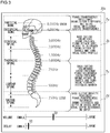
- Fig. 2 shows the first example of a user operation screen 25a displayed on the display interface 25.
- the user operation screen 25a shown in Fig. 2 shows correspondence between the frequency range desired to be enhanced by the vibrator 33 and the site of the human body that should be fitted with the vibrator 33.
- the frequency range enhanced by the vibrator 33 is organized into four groups. The characteristic of the sound in each frequency range is expressed by words.
- Fig. 2 shows that the frequency range is organized into four groups including a range equal to higher than 4 kHz (A range), a range 4 kHz-1 kHz (B range), a range 1 kH-375 Hz (C range), and a range equal to or lower than 375 Hz (D range).
- the user can select a range desired to be enhanced from the four ranges.
- the sound in the A range is expressed as being characterized by brilliance, luster, and transparency. It is indicated that the vibrator 33 should be fitted to a position corresponding to the upper part of the skull bone when the A range is selected.
- the sound in the B range is expressed as being characterized by thickness and core in the high-range. It is indicated that the vibrator 33 should be fitted to a position corresponding to the range between the lower part of the skull bone and the center of the breastbone when the B range is selected.
- the sound in the C range is expressed as being characterized by voluminousness. It is indicated that the vibrator 33 should be fitted to a position corresponding to the range between the center of the breastbone and the lower end of the hip bone when the C range is selected.
- the sound in the D range is expressed as being characterized by thickness, mass, depth of bass tone. It is indicated that the vibrator 33 should be fitted to a position corresponding to the range between the lower end of the hip bone and the lower end of the sacral spine when the D range is selected.
- the user can select the A range by touching a zone Za in the user operation screen 25a corresponding to the A range, select the B range by touching a zone Zb corresponding to the B range, select the C range by touching a zone Zc corresponding to the C range, and select the D range by touching a zone Zd corresponding to the D range.
- the user operation screen 25a shows a volume adjustment bar for adjusting the volume of vibration of the vibrator 33 and a delay adjustment bar for adjusting the amount of delay in the vibrational output from the vibrator 33 relative to the sound wave output from the earphone/headphone 40.
- the user can adjust the volume of vibration of the vibrator 33 by controlling a slide bar S1 on the volume adjustment slide bar and can adjust the amount of delay of vibrational output of the vibrator 33 by controlling a slide bar S2 on the delay adjustment bar.
- Fig. 3 shows the second example of a user operation screen 25b displayed on the display interface 25.
- the frequency range enhanced by the vibrator 33 is organized into four groups. The characteristic of the sound of musical instruments and the sound of vocal performance in each frequency range is expressed by words.
- the sound in the A range is characterized by expressing the sound of piano as being characterized by transparency and brilliance, the sound of drums as being characterized by clearly-defined hat beats, and the sound of vocal performance as being characterized by brilliance, luster, and transparency.
- the sound in the B range is characterized by expressing the sound of a bass guitar as being characterized by voluminous sound and presence, the sound of piano as being characterized by attack, core, weight of the keyboard, and the sound of drums as being characterized by attack of snares and toms, and the sound of vocal performance as being characterized by core and profile.
- the sound in the C range is characterized by expressing the sound of a bass guitar as being characterized by voluminous sound and presence, the sound of piano as being characterized by voluminous sound and presence, the sound of drums as being characterized by attack of snares and toms, and the sound of vocal performance as being characterized by vibrancy, thickness, and warmth.
- the sound in the D range is characterized by expressing the sound of a bass guitar as being characterized by gravity and heaviness, the sound of piano as being characterized by powerfulness and thickness, the sound of drums as being characterized by thickness and depth of kicks, and the sound of vocal performance as being characterized by depth, and resonance in the chest.
- the other parts of the display are the same as those of the user operation screen 25a of Fig. 2 .
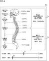
- Fig. 4 shows the third example of a user operation screen 25c displayed on the display interface 25.
- the frequency range desired to be enhanced by the vibrator 33 is organized according to music genre. Referring to Fig. 4 , the frequency range is organized into two ranges including a range equal to higher than 1 kHz (A range) and a range below 1 kHz (B range). The user can select the range desired to be enhanced from the two ranges.
- music characterized by rhythm and attack, pops, classical are indicated as the music genre in the A range. It is indicated that the vibrator 33 should be fitted to a position corresponding to the range between the upper end of the skull bone and the center of the breastbone when the A range is selected.
- Music characterized by beat, vocal music, rock, and jazz are indicated as the music genre in the B range. It is indicated that the vibrator 33 should be fitted to a position corresponding to the range between the center of the breastbone and the lower end of the sacral spine when the B range is selected.
- the user can select the A range by touching the zone Za in the user operation screen 25c corresponding to the A range and select the B range by touching the zone Zb corresponding to the B range.
- the user operation screens 25a-25c shown in Figs. 2-4 are by way of examples only, and the screen may have another format.
- the screen may be formatted to allow the user to designate the upper limit and the lower limit of the frequency range desired to be enhanced, using specific numerical values.
- Figs. 5A and 5B show specific examples of fitting the vibrator device 30.
- Fig. 5A shows an example in which the vibrator device 30 is fitted inside a belt B1 of an underwear or a skirt.
- the vibrator device 30 is plate-shaped, and the vibrating surface of the vibrator device 30 is fitted to and in contact with the human body.
- the vibrator device 30 is housed in a simple case and is fixed inside the belt B1 by a clip.
- the back surface of the vibrator device 30 may be fixed inside the belt B1 by using a hook and loop fastener (e.g., a Velcro (registered trademark)).
- Fig. 5B shows a case in which the vibrator device 30 is fitted inside a seat belt B2.
- the shape and the method of fitting of the vibrator device 30 shown in Figs 5A and 5B are by way of examples only and are not limited to those shown in Figs. 5A and 5B .
- this embodiment enables enjoying a sense of realism and a sense of immersion that cannot be enjoyed with the earphone/headphone 40 alone, by fitting the vibrator 33 to a site other than the site fitted with the earphone/headphone 40.
- the vibrator 33 by driving the vibrator 33 with the music signal output from the preamplifier 22 and delivering the vibration to the human body, powerful music experience that accompanies a synergistic effect of the sound of the earphone/headphone 40 and the vibration can be realized.
- the resonance frequency of the vibrator 33 Since the resonance of the body (bone) is utilized, the precision of the resonance frequency of the vibrator 33 is not required, and an experience of bass and a sense of realism can be felt not only by the ear but by the whole body.
- the resonance frequency and position of fitting of the vibrator are fixed. Therefore, vibration near the resonance frequency of the vibrator is unexceptionally large, making it difficult to obtain only the vibration in the range desired to be experienced.
- the vibrator 33 can be fitted to a desired site of the body. In the case an experience of bass is desired, for example, the sense of realism can be improved by fitting the vibrator 33 to the waist.
- the range and volume of the music signal converted into vibration can be adjusted individually, and the time difference from the sound wave output from the earphone/headphone 40 can also be adjusted. Accordingly, flexible adjustment suited to personal preferences is possible so that the sense of immersion is further improved.
- the system can be used in combination with the existent music player 10 or the existent earphone/headphone 40 so that the cost of introducing the vibration generation system 1 incurred by the user is low, and existent resources can be utilized effectively. Further, visual presentation of the correspondence between the frequency range enhanced and the site of the body that should be fitted with the vibrator 33 allows the user to use the vibration generation system 1 according to this embodiment easily.
- Fig. 6 is a graph showing an equal loudness curve.
- the equal loudness curve shown in Fig. 6 is an equal loudness curve standardized in ISO0226:2003.
- An equal loudness level curve is a frequency characteristic curve created by connecting sound pressure levels sensed by the human ear to be of the same level as the frequency of sound is changed.
- NIHL chronic noise-induced hearing loss
- the human ear is most sensitive in 2 kHz-4 kHz. Therefore, a lot of users control the sound volume of a headphone etc. based on the sound in the 2 kHz-4 kHz range.
- the sound pressure level at 2 kHz-4 kHz in the equal loudness curve for 80 phon is about 78 dB
- the sound pressure level at 125 Hz in the equal loudness curve for 80 phon is about 90 dB.
- the difference is about 12 dB. If the sound volume is controlled in the range 2 kHz-4 kHz based on the equal loudness curve for 80 phon, the ear will be exposed to a sound pressure exceeding 90 dB at 125 kHz or below.
- the reference line in the equal loudness curve can be lowered from 80 phon.
- the user is expected to lower the overall sound volume of the headphone etc., and the likelihood that the user's ear is exposed to a sound pressure exceeding 90 dB can be reduced.
- Fig. 7 is a block diagram showing a configuration of the vibration generation system 1 according to variation 1.
- Variation 1 is configured such that the function of the signal generator 20 of the vibration generation system 1 shown in Fig. 1 is built in the music player 10.
- the system can be configured by installing an application program for implementing the function of the preamplifier 22 in digital signal processing.
- the music player 10 may be comprised of a special-purpose DAP in which the function of the preamplifier 22 is built in from the beginning.
- music data is directly supplied from a music data storage 11 to the preamplifier 22 in the music player 10 so that communication between the music player 10 and the signal generator 20 is unnecessary.
- Fig. 8 is a block diagram showing a configuration of the vibration generation system 1 according to variation 2.
- a plurality of vibrator devices 30a, 30b are used. Inside the signal generator 20 are provided a plurality of preamplifiers 22a, 22b and a plurality of output interfaces 23a, 23b corresponding to the plurality of vibrator devices 30a, 30b. It is difficult for a single vibrator 33 to cover vibration in a wide range. A more extensive range of vibration can be generated by providing the vibrator device 30a for low-range and the vibrator device 30b for high-range. In the case the plurality of vibrator devices 30a, 30b are provided, the devices are fitted to different sites of the human body in accordance with the respective extracted frequency range.
- the plurality of vibrator devices 30a, 30b may be comprised of the vibrator device 30a vibrated based on a left channel signal and the vibrator device 30b vibrated based on a right channel signal.
- the user manually sets the frequency range, volume, and time adjusted by the preamplifier 22.
- the music player 10 or the signal generator 20 is connected to the internet, it is possible to acquire attribute information such as genre of music data to allow the controller to set the frequency range, volume, and time automatically.
- an AI engine frequency determination interface
- vibration generation system 10 music player, 11 music data storage, 20 signal generator, 21 input interface, 211 wired input interface, 212 wireless communication interface, 22 preamplifier, 221 signal processor, 222 variable filter, 223 variable amplifier, 224 variable delayer, 23 output interface, 231 wireless communication interface, 24 controller, 25 display interface, 26 user operation interface, 30 vibrator device, 31 input interface, 311 wireless communication interface, 32 driving controller, 321 amplifier, 322 adjuster, 33 vibrator, 40 earphone/headphone, J1 input-side phone jack, J2 output-side phone jack
- the present invention is applicable to music experience in which a vibrator is used.
Landscapes
- Engineering & Computer Science (AREA)
- Physics & Mathematics (AREA)
- Signal Processing (AREA)
- Acoustics & Sound (AREA)
- Health & Medical Sciences (AREA)
- Theoretical Computer Science (AREA)
- Mechanical Engineering (AREA)
- Audiology, Speech & Language Pathology (AREA)
- General Engineering & Computer Science (AREA)
- General Physics & Mathematics (AREA)
- Human Computer Interaction (AREA)
- General Health & Medical Sciences (AREA)
- Multimedia (AREA)
- Otolaryngology (AREA)
- Details Of Audible-Bandwidth Transducers (AREA)
- Circuit For Audible Band Transducer (AREA)
- Apparatuses For Generation Of Mechanical Vibrations (AREA)
Abstract
Description
- The present invention relates to a vibration generation system, a signal generator, and a vibrator device provided with a vibrator fitted to the human body for use.
- It is difficult to reproduce powerful deep bass with an earphone or a headphone. To reproduce powerful deep bass, a long-stroke speaker is necessary, and it is difficult to secure a stroke of a speaker in small-sized earphones and headphones such as a canal type earphone.
- To address the issue, there is proposed a body vibration headphone in which a vibration unit capable of transforming a low-range signal into mechanical vibration is mounted (see, for example, patent document 1). A body vibration headphone can reproduce an experience of bass or a sense of realism to a certain degree. There is also proposed an acoustic vibrating rod system in which a music signal from a CD player is caused to branch to a music signal for vibration and a music signal for the speaker/earphone, the music signal for vibration is fed to a vibrator, the vibrating rod is vibrated in resonance with the vibration of the vibrator, and the vibration is propagated from the part in contact with the skin (see, for example, patent literature 2) .
-
- [Patent Literature 1]
JP2016-178627 - [Patent Literature 2]
JP2013-48870 - Merely building a vibrator into a headphone as in case of the above-mentioned body vibration headphone can address personal preferences, express music, or provide a sense of immersion only to a limited degree and so is insufficient to fulfill extensive need for music experience. Similarly, systems like the aforementioned acoustic vibrating rod system that vibrate a vibrating rod in resonance with the vibration of the vibrator have also been insufficient to fulfill extensive need for music experience.
- The present invention addresses the above-described issue, and a general purpose thereof is to provide a technology for realizing more flexible and more vivid music experience.
- A vibration generation system according to an embodiment includes: a vibrator fitted to a human body for use; a variable filter that extracts a signal of a predefined frequency range from an input music signal; a driver that drives the vibrator based on the signal of the frequency range extracted by the variable filter; and a user operation interface with which it is possible to adjust the frequency range that is predefined.
- Another embodiment relates to a signal generator. The signal generator is connected by wire or wirelessly to a vibrator device including a vibrator fitted to a human body for use and a driver for driving the vibrator, the signal generator including: a variable filter that extracts a signal of a predefined frequency range from a music signal; an output interface that outputs the signal of the frequency range extracted by the variable filter to the vibrator device; and a user operation interface with which it is possible to adjust the frequency range that is predefined.
- Still another embodiment relates to a vibrator device. The device is connected by wire or wirelessly to a signal generator including a variable filter that extracts, from a music signal, a signal of a predefined frequency range, an output interface that outputs the signal of the frequency range extracted by the variable filter, and a user operation interface with which it is possible to adjust the frequency range that is predefined, the vibrator device including: a vibrator fitted to a human body for use; an input interface that acquires, from the signal generator, the signal of the frequency extracted by the variable filter; and a driver that drives the vibrator based on the input signal of the frequency range extracted by the variable filter.
- Optional combinations of the aforementioned constituting elements, and implementations of the embodiment in the form of methods, apparatuses, systems, and computer programs, etc. may also be practiced as additional modes of the embodiments.
- According to the present invention, it is possible to realize more flexible and more vivid music experience.
-
-
Fig. 1 is a block diagram showing a configuration of a vibration generation system according to an embodiment of the present invention; -
Fig. 2 shows the first example of a user operation screen displayed on the display interface; -
Fig. 3 shows the second example of a user operation screen displayed on the display interface; -
Fig. 4 shows the third example of a user operation screen displayed on the display interface; -
Figs. 5A and 5B show specific examples of fitting the vibrator device; -
Fig. 6 is a graph showing an equal loudness curve; -
Fig. 7 is a block diagram showing a configuration of the vibration generation system according tovariation 1; and -
Fig. 8 is a block diagram showing a configuration of the vibration generation system according tovariation 2. -
Fig. 1 is a block diagram showing a configuration of avibration generation system 1 according to an embodiment of the present invention. Thevibration generation system 1 is used in combination with anexistent music player 10 and an earphone/headphone 40. A smartphone, a digital audio player (DAP), a CD player, etc. can be used as themusic player 10. Earphones like an overhead earphone, a canal type earphone, an inner-ear earphone can be used as the earphone/headphone 40. A wireless earphone/headphone 40 can also be used. - The
vibration generation system 1 is provided with asignal generator 20 and avibrator device 30. Thesignal generator 20 is provided with aninput interface 21, apreamplifier 22, anoutput interface 23, acontroller 24, adisplay interface 25, auser operation interface 26, an input-side phone jack J1, and an output-side phone jack J2. Theinput interface 21 of thesignal generator 20 includes awired input interface 211 and awireless communication interface 212. - The
signal generator 20 and themusic player 10 are connected by wire or wirelessly. In the case they are connected by wire, they are connected by a cable fitted with phone plugs at the respective ends. A phone plug at one end of the cable is inserted into the input-side phone jack J1 of thesignal generator 20. In the case thesignal generator 20 and themusic player 10 are connected wirelessly, they are connected by near field wireless communication (Bluetooth (registered trademark) is assumed in this specification). - The signal line connected to the input-side phone jack J1 branches in the housing of the
signal generator 20 and is connected to the output-side phone jack J2 and awired input interface 211, respectively. Thewired input interface 211 acquires a music signal output from themusic player 10 and outputs the signal to thepreamplifier 22. In the case the music signal is a stereo signal, thewired input interface 211 acquires a left channel signal and a right channel signal from themusic player 10. An MP3 sound source, a CD sound source, a high-resolution sound source, etc. can be used as the source of the music signal. - A phone plug of the cable connected to the earphone/
headphone 40 can be inserted into the output-side phone jack J2 of thesignal generator 20. In this mode of connection, thesignal generator 20 imports the music signal input from themusic player 10 via thewired input interface 211 and also passes the signal through to the earphone/headphone 40. - The
wireless communication interface 212 is provided with an antenna (not shown) and performs a communication process for near field wireless communication via the antenna. Referring toFig. 1 , thewireless communication interface 212 is paired with a wireless communication interface (not shown) of themusic player 10, receives the music signal transmitted from themusic player 10 by near field wireless communication, and outputs the received signal to thepreamplifier 22. - In the case the wireless earphone/
headphone 40 is used, the wireless communication interface (not shown) of the earphone/headphone 40 is paired with the wireless communication interface (not shown) of themusic player 10, and themusic player 10 transmits the music signal to the earphone/headphone 40 by near field wireless communication. The music signal transmitted to the earphone/headphone 40 and the music signal transmitted to thesignal generator 20 are basically the same. -
Fig. 1 shows an exemplary configuration in which thesignal generator 20 can be connected to themusic player 10 either by wire or wirelessly. In the case of employing a configuration in which only wired connection is enabled, thewireless communication interface 212 is omitted. In the case of employing a configuration in which only wireless connection is enabled, thewired input interface 211, the input-side phone jack J1, and the output-side phone jack J2 are omitted. - The
preamplifier 22 includes asignal processor 221, avariable filter 222, avariable amplifier 223, and avariable delayer 224. Thesignal processor 221 synthesizes the left channel signal and the right channel signal to generate a monaural signal and outputs the synthesized signal to thevariable filter 222. Only one of the left channel signal and the right channel signal may be output to thevariable filter 222. In the case a monaural signal is input to thepreamplifier 22, thesignal processor 221 directly outputs the monaural signal to thevariable filter 222. In the case twovibrator 33 including the one for left (L) and the one for right (R), the left channel signal and the right channel signal (stereo signal) are directly output to thevariable filter 222. Stereophonic sound is expected to offer an advantage of, for example, duplicating a hall sound in the mid to high range. - The
variable filter 222 extracts a signal in a predefined frequency range from the input music signal. Thevariable filter 222 includes at least one of a low-pass filter, a bandpass filter, and a bypass filter. The low-pass filter, the bandpass filter, and the bypass filter may be comprised of an analog circuit or implemented by digital signal processing. The cutoff frequency of the low-pass filter, the upper cutoff frequency and the lower cutoff frequency of the bandpass filter, and the cutoff frequency of the bypass filter are variable. - In the case the low-pass filter, the bandpass filter, and the bypass filter are comprised of an analog circuit, the respective cutoff frequencies can be adjusted by configuring the constant of the resistance or capacitance to be variable. In the case the low-pass filter, the bandpass filter, and the bypass filter are comprised of a digital filter (e.g., an infinite impulse response (IIR) filter or a finite impulse response (FIR) filter), the respective cutoff frequencies can be adjusted by configuring the sampling period or weight coefficient to be variable.
- The
variable amplifier 223 amplifies the music signal of the frequency range extracted by thevariable filter 222 by a predefined gain. This adjusts the volume (vibration quantity) of the music signal. - The
variable delayer 224 delays the music signal subjected to gain control by thevariable amplifier 223 by a predefined amount of delay. This adjusts the time difference between the sound wave transmitted from the earphone/headphone 40 to the ear and the vibration transmitted from thevibrator 33 to the human body (bone). Thevariable delayer 224 may be omitted. In that case, the amount of delay is fixed. - The music signal, for which at least one of the frequency range, volume, and time is adjusted by the
preamplifier 22, is output to theoutput interface 23. Theoutput interface 23 includes awireless communication interface 231. Thewireless communication interface 231 is provided with an antenna (not shown) and performs a communication process for near field wireless communication via the antenna. Referring toFig. 1 , thewireless communication interface 231 is paired with awireless communication interface 311 of thevibrator device 30 and transmits the music signal adjusted by thepreamplifier 22 and range information extracted by thepreamplifier 22 to thewireless communication interface 311 by near field wireless communication. Thesignal generator 20 and thevibrator device 30 may be connected by a wiring cable. In that case, a wired output interface is provided in thesignal generator 20 to replace thewireless communication interface 231, and a wired input interface is provided in thevibrator device 30 to replace thewireless communication interface 311. - The
controller 24 controls the entirety of thesignal generator 20. Thecontroller 24 is comprised of, for example, a microprocessor. Thedisplay interface 25 is provided with a display such as a liquid crystal display and an organic EL display and displays the image generated by thecontroller 24. Theuser operation interface 26 is provided with a user interface such as a switch, a button, a dial knob, and a touch panel and receives a user operation. Thedisplay interface 25 and theuser operation interface 26 may be integrated in a touch panel display. - The
controller 24 sets a frequency range desired to be extracted in thevariable filter 222, sets the gain in thevariable amplifier 223, and sets the amount of delay in thevariable delayer 224, based on the user operation in theuser operation interface 26. - The
vibrator device 30 is provided with aninput interface 31, a drivingcontroller 32, and avibrator 33. Theinput interface 31 includes thewireless communication interface 311. The drivingcontroller 32 includes anamplifier 321 and anadjuster 322. Thewireless communication interface 311 is paired with thewireless communication interface 231 of thesignal generator 20 and receives the music signal and the range information transmitted from thesignal generator 20 by near field wireless communication. Thewireless communication interface 311 outputs the music signal to theamplifier 321 and outputs the range information to theadjuster 322. - The
vibrator 33 is fitted to an arbitrary position of the human body for use. Any of existent electrodynamic, piezoelectric, electrostatic vibrators may be used as thevibrator 33. It is preferred to use a vibrator with a high response speed from the perspective of reducing the time difference between the sound wave transmitted from the earphone/headphone 40 to the ear and the vibration transmitted from thevibrator 33 to the human body (bone). - The
amplifier 321 converts the music signal input from theinput interface 31 into a driving signal for thevibrator 33. In the case theelectrodynamic vibrator 33 is used, for example, theamplifier 321 converts the music signal into a driving current induced in the coil. In the case thepiezoelectric vibrator 33 is used, theamplifier 321 converts the music signal into a voltage applied to the piezoelectric device. - The
adjuster 322 adjusts the resonance frequency of thevibrator 33 to an optimum frequency based on the input range information. Theadjuster 322 causes, within a range in which the resonance frequency of thevibrator 33 is adjustable, the resonance frequency of thevibrator 33 to approach the central frequency of the range included in the range information and extracted by thepreamplifier 22. Theadjuster 322 can adjust the resonance frequency of thevibrator 33 by displacing the physical property (e.g., spring constant) of thevibrator 33. Some piezoelectric devices are configured such that the resonance frequency can be adjusted by electrical control. In that case, the resonance frequency of thevibrator 33 can be adjusted by adjusting the voltage. - In the case the
vibrator 33 in which the resonance frequency cannot be adjusted is used, theadjuster 322 is omitted. In that case, the resonance frequency of thevibrator 33 is fixed. - The vibration level of the
vibrator 33 that can be experienced varies greatly depending on the site of the human body fitted with thevibrator 33. This is considered to be because of the impact of the resonance frequency in bone vibration. According to the study by Dr. Alfred Tomatis, the resonance frequency in bone vibration is higher in the skull bone than in the backbone. The higher up in the backbone from the sacral spine to the lumbar spine, the thoracic spine, and the cervical spine, the higher the resonance frequency. The resonance frequency in the parietal bone is higher in the parietal bone than in the occipital bone. Therefore, the lower in the backbone the vibrator is fitted, the larger the vibration level that can be experienced. This is especially true in the case of low-range vibration. When it is desired to enhance the low range that is difficult to reproduce with the earphone/headphone 40, it is effective to fit thevibrator 33 to the waist. However, few ordinary users have knowledge about the resonance frequency of the bone, and it is desired to provide a user interface that guides the user to the position where thevibrator 33 should be fitted. -
Fig. 2 shows the first example of auser operation screen 25a displayed on thedisplay interface 25. Theuser operation screen 25a shown inFig. 2 shows correspondence between the frequency range desired to be enhanced by thevibrator 33 and the site of the human body that should be fitted with thevibrator 33. Referring toFig. 2 , the frequency range enhanced by thevibrator 33 is organized into four groups. The characteristic of the sound in each frequency range is expressed by words.Fig. 2 shows that the frequency range is organized into four groups including a range equal to higher than 4 kHz (A range), a range 4 kHz-1 kHz (B range), arange 1 kH-375 Hz (C range), and a range equal to or lower than 375 Hz (D range). The user can select a range desired to be enhanced from the four ranges. - Referring to
Fig. 2 , the sound in the A range is expressed as being characterized by brilliance, luster, and transparency. It is indicated that thevibrator 33 should be fitted to a position corresponding to the upper part of the skull bone when the A range is selected. The sound in the B range is expressed as being characterized by thickness and core in the high-range. It is indicated that thevibrator 33 should be fitted to a position corresponding to the range between the lower part of the skull bone and the center of the breastbone when the B range is selected. The sound in the C range is expressed as being characterized by voluminousness. It is indicated that thevibrator 33 should be fitted to a position corresponding to the range between the center of the breastbone and the lower end of the hip bone when the C range is selected. The sound in the D range is expressed as being characterized by thickness, mass, depth of bass tone. It is indicated that thevibrator 33 should be fitted to a position corresponding to the range between the lower end of the hip bone and the lower end of the sacral spine when the D range is selected. - The user can select the A range by touching a zone Za in the
user operation screen 25a corresponding to the A range, select the B range by touching a zone Zb corresponding to the B range, select the C range by touching a zone Zc corresponding to the C range, and select the D range by touching a zone Zd corresponding to the D range. - The
user operation screen 25a shows a volume adjustment bar for adjusting the volume of vibration of thevibrator 33 and a delay adjustment bar for adjusting the amount of delay in the vibrational output from thevibrator 33 relative to the sound wave output from the earphone/headphone 40. The user can adjust the volume of vibration of thevibrator 33 by controlling a slide bar S1 on the volume adjustment slide bar and can adjust the amount of delay of vibrational output of thevibrator 33 by controlling a slide bar S2 on the delay adjustment bar. -
Fig. 3 shows the second example of auser operation screen 25b displayed on thedisplay interface 25. In theuser operation screen 25b shown inFig. 3 , the frequency range enhanced by thevibrator 33 is organized into four groups. The characteristic of the sound of musical instruments and the sound of vocal performance in each frequency range is expressed by words. - Referring to
Fig. 3 , the sound in the A range is characterized by expressing the sound of piano as being characterized by transparency and brilliance, the sound of drums as being characterized by clearly-defined hat beats, and the sound of vocal performance as being characterized by brilliance, luster, and transparency. The sound in the B range is characterized by expressing the sound of a bass guitar as being characterized by voluminous sound and presence, the sound of piano as being characterized by attack, core, weight of the keyboard, and the sound of drums as being characterized by attack of snares and toms, and the sound of vocal performance as being characterized by core and profile. The sound in the C range is characterized by expressing the sound of a bass guitar as being characterized by voluminous sound and presence, the sound of piano as being characterized by voluminous sound and presence, the sound of drums as being characterized by attack of snares and toms, and the sound of vocal performance as being characterized by vibrancy, thickness, and warmth. The sound in the D range is characterized by expressing the sound of a bass guitar as being characterized by gravity and heaviness, the sound of piano as being characterized by powerfulness and thickness, the sound of drums as being characterized by thickness and depth of kicks, and the sound of vocal performance as being characterized by depth, and resonance in the chest. The other parts of the display are the same as those of theuser operation screen 25a ofFig. 2 . -
Fig. 4 shows the third example of auser operation screen 25c displayed on thedisplay interface 25. In theuser operation screen 25c shown inFig. 4 , the frequency range desired to be enhanced by thevibrator 33 is organized according to music genre. Referring toFig. 4 , the frequency range is organized into two ranges including a range equal to higher than 1 kHz (A range) and a range below 1 kHz (B range). The user can select the range desired to be enhanced from the two ranges. - Referring to
Fig. 4 , music characterized by rhythm and attack, pops, classical are indicated as the music genre in the A range. It is indicated that thevibrator 33 should be fitted to a position corresponding to the range between the upper end of the skull bone and the center of the breastbone when the A range is selected. Music characterized by beat, vocal music, rock, and jazz are indicated as the music genre in the B range. It is indicated that thevibrator 33 should be fitted to a position corresponding to the range between the center of the breastbone and the lower end of the sacral spine when the B range is selected. - The user can select the A range by touching the zone Za in the
user operation screen 25c corresponding to the A range and select the B range by touching the zone Zb corresponding to the B range. - The user operation screens 25a-25c shown in
Figs. 2-4 are by way of examples only, and the screen may have another format. For example, the screen may be formatted to allow the user to designate the upper limit and the lower limit of the frequency range desired to be enhanced, using specific numerical values. -
Figs. 5A and 5B show specific examples of fitting thevibrator device 30.Fig. 5A shows an example in which thevibrator device 30 is fitted inside a belt B1 of an underwear or a skirt. Thevibrator device 30 is plate-shaped, and the vibrating surface of thevibrator device 30 is fitted to and in contact with the human body. For example, thevibrator device 30 is housed in a simple case and is fixed inside the belt B1 by a clip. Alternatively, the back surface of thevibrator device 30 may be fixed inside the belt B1 by using a hook and loop fastener (e.g., a Velcro (registered trademark)).Fig. 5B shows a case in which thevibrator device 30 is fitted inside a seat belt B2. The shape and the method of fitting of thevibrator device 30 shown inFigs 5A and 5B are by way of examples only and are not limited to those shown inFigs. 5A and 5B . - As described above, this embodiment enables enjoying a sense of realism and a sense of immersion that cannot be enjoyed with the earphone/
headphone 40 alone, by fitting thevibrator 33 to a site other than the site fitted with the earphone/headphone 40. In other words, by driving thevibrator 33 with the music signal output from thepreamplifier 22 and delivering the vibration to the human body, powerful music experience that accompanies a synergistic effect of the sound of the earphone/headphone 40 and the vibration can be realized. - Since the resonance of the body (bone) is utilized, the precision of the resonance frequency of the
vibrator 33 is not required, and an experience of bass and a sense of realism can be felt not only by the ear but by the whole body. In the related-art vibrator with a built-in headphone, the resonance frequency and position of fitting of the vibrator are fixed. Therefore, vibration near the resonance frequency of the vibrator is unexceptionally large, making it difficult to obtain only the vibration in the range desired to be experienced. - In the
vibration generation system 1 according to this embodiment, on the other hand, it is possible to limit the frequency range by means of the built-invariable filter 222, and it is possible to inhibit unnecessary music signals (vibration). In further accordance with thevibration generation system 1 according to this embodiment, thevibrator 33 can be fitted to a desired site of the body. In the case an experience of bass is desired, for example, the sense of realism can be improved by fitting thevibrator 33 to the waist. - Further, the range and volume of the music signal converted into vibration can be adjusted individually, and the time difference from the sound wave output from the earphone/
headphone 40 can also be adjusted. Accordingly, flexible adjustment suited to personal preferences is possible so that the sense of immersion is further improved. - Further, the system can be used in combination with the
existent music player 10 or the existent earphone/headphone 40 so that the cost of introducing thevibration generation system 1 incurred by the user is low, and existent resources can be utilized effectively. Further, visual presentation of the correspondence between the frequency range enhanced and the site of the body that should be fitted with thevibrator 33 allows the user to use thevibration generation system 1 according to this embodiment easily. - The
vibration generation system 1 according to this embodiment is also advantageous for the purpose of preventing difficulty in hearing.Fig. 6 is a graph showing an equal loudness curve. The equal loudness curve shown inFig. 6 is an equal loudness curve standardized in ISO0226:2003. An equal loudness level curve is a frequency characteristic curve created by connecting sound pressure levels sensed by the human ear to be of the same level as the frequency of sound is changed. - According to the guideline from Occupational Safety and Health Administration (OSHA), it is reported that exposure to excessively large sound for a long period of time may cause a damage to the ear and induce chronic noise-induced hearing loss (NIHL). The above guideline prescribes the duration for which people can be exposed to respective sound pressures without experiencing hearing loss as follows.
- 90 dB SPL 8 hours
- 95 dB SPL 4 hours
- 100
dB SPL 2 hours - 105
dB SPL 1 hour - 110
dB SPL 30 minutes - 115 dB SPL 15 minutes
- 120 dB SPL to be avoided
- Normally, the human ear is most sensitive in 2 kHz-4 kHz. Therefore, a lot of users control the sound volume of a headphone etc. based on the sound in the 2 kHz-4 kHz range. Referring to
Fig. 6 , the sound pressure level at 2 kHz-4 kHz in the equal loudness curve for 80 phon is about 78 dB, and the sound pressure level at 125 Hz in the equal loudness curve for 80 phon is about 90 dB. The difference is about 12 dB. If the sound volume is controlled in therange 2 kHz-4 kHz based on the equal loudness curve for 80 phon, the ear will be exposed to a sound pressure exceeding 90 dB at 125 kHz or below. In this case, the danger of inducing hearing disorder is increased. As indicated in the above guideline, prolonged exposure of the ear to a sound pressure of 90 dB or higher (see an area A1 inFig. 6 ) may carry the danger of inducing hearing disorder. - By switching (compensating) the sound in the area A1 to (with) the vibration produced by the
vibrator 33, the reference line in the equal loudness curve can be lowered from 80 phon. With this, the user is expected to lower the overall sound volume of the headphone etc., and the likelihood that the user's ear is exposed to a sound pressure exceeding 90 dB can be reduced. - Described above is an explanation of the present invention based on an exemplary embodiment. The embodiment is intended to be illustrative only and it will be understood by those skilled in the art that various modifications to combinations of constituting elements and processes are possible and that such modifications are also within the scope of the present invention.
-
Fig. 7 is a block diagram showing a configuration of thevibration generation system 1 according tovariation 1.Variation 1 is configured such that the function of thesignal generator 20 of thevibration generation system 1 shown inFig. 1 is built in themusic player 10. In the case that themusic player 10 is a smartphone, for example, the system can be configured by installing an application program for implementing the function of thepreamplifier 22 in digital signal processing. Alternatively, themusic player 10 may be comprised of a special-purpose DAP in which the function of thepreamplifier 22 is built in from the beginning. Invariation 1, music data is directly supplied from amusic data storage 11 to thepreamplifier 22 in themusic player 10 so that communication between themusic player 10 and thesignal generator 20 is unnecessary. -
Fig. 8 is a block diagram showing a configuration of thevibration generation system 1 according tovariation 2. Invariation 2, a plurality ofvibrator devices signal generator 20 are provided a plurality ofpreamplifiers output interfaces vibrator devices single vibrator 33 to cover vibration in a wide range. A more extensive range of vibration can be generated by providing thevibrator device 30a for low-range and thevibrator device 30b for high-range. In the case the plurality ofvibrator devices vibrator devices vibrator device 30a vibrated based on a left channel signal and thevibrator device 30b vibrated based on a right channel signal. - In the embodiment described above, an example is described in which the user manually sets the frequency range, volume, and time adjusted by the
preamplifier 22. In the case themusic player 10 or thesignal generator 20 is connected to the internet, it is possible to acquire attribute information such as genre of music data to allow the controller to set the frequency range, volume, and time automatically. It is also possible to cause an AI engine (frequency determination interface) inside or outside the device to analyze a plurality of music signals, and at least one of the frequency range, volume, and time may be automatically adjusted based on the result of analysis and the music signals subjected to the analysis. - 1 vibration generation system, 10 music player, 11 music data storage, 20 signal generator, 21 input interface, 211 wired input interface, 212 wireless communication interface, 22 preamplifier, 221 signal processor, 222 variable filter, 223 variable amplifier, 224 variable delayer, 23 output interface, 231 wireless communication interface, 24 controller, 25 display interface, 26 user operation interface, 30 vibrator device, 31 input interface, 311 wireless communication interface, 32 driving controller, 321 amplifier, 322 adjuster, 33 vibrator, 40 earphone/headphone, J1 input-side phone jack, J2 output-side phone jack
- The present invention is applicable to music experience in which a vibrator is used.
Claims (9)
- A vibration generation system comprising:a vibrator fitted to a human body for use;a variable filter that extracts a signal of a predefined frequency range from an input music signal;a driver that drives the vibrator based on the signal of the frequency range extracted by the variable filter; anda user operation interface with which it is possible to adjust the frequency range that is predefined.
- The vibration generation system according to claim 1, further comprising:
a frequency determination interface that determines the frequency range that is predefined, based on the music signal. - The vibration generation system according to claim 1 or 2, further comprising:
a display interface that displays a screen showing correspondence between the frequency range that is predefined and a site of the human body that should be fitted with the vibrator. - The vibration generation system according to one of claims 1 through 3, wherein
the frequency range that is predefined is organized into groups according to music genre. - The vibration generation system according to one of claims 1 through 3, wherein
the frequency range that is predefined is organized into groups according to a characteristic of sound of a musical instrument and/or vocal performance. - The vibration generation system according to one of claims 1 through 5, further comprising:a variable amplifier provided in a stage that follows the variable filter, whereinit is possible to adjust a gain of the variable amplifier by using the user operation interface.
- The vibration generation system according to one of claims 1 through 6, wherein
a plurality of pairs of the vibrator and the variable filter are provided, and
it is possible to fit a plurality of vibrators to different sites of the human body, respectively. - A signal generator connected by wire or wirelessly to a vibrator device including a vibrator fitted to a human body for use and a driver for driving the vibrator, the signal generator comprising:a variable filter that extracts a signal of a predefined frequency range from a music signal;an output interface that outputs the signal of the frequency range extracted by the variable filter to the vibrator device; anda user operation interface with which it is possible to adjust the frequency range that is predefined.
- A vibrator device connected by wire or wirelessly to a signal generator including a variable filter that extracts, from a music signal, a signal of a predefined frequency range, an output interface that outputs the signal of the frequency range extracted by the variable filter, and a user operation interface with which it is possible to adjust the frequency range that is predefined, the vibrator device comprising:a vibrator fitted to a human body for use;an input interface that acquires, from the signal generator, the signal of the frequency extracted by the variable filter; anda driver that drives the vibrator based on the input signal of the frequency range extracted by the variable filter.
Applications Claiming Priority (2)
| Application Number | Priority Date | Filing Date | Title |
|---|---|---|---|
| JP2018004895A JP7254443B2 (en) | 2018-01-16 | 2018-01-16 | Vibration generation system, signal generation device, and vibrating device |
| PCT/JP2018/032634 WO2019142390A1 (en) | 2018-01-16 | 2018-09-03 | Vibration generation system, signal generation device, and vibratory device |
Publications (3)
| Publication Number | Publication Date |
|---|---|
| EP3742750A1 true EP3742750A1 (en) | 2020-11-25 |
| EP3742750A4 EP3742750A4 (en) | 2021-02-17 |
| EP3742750B1 EP3742750B1 (en) | 2022-03-09 |
Family
ID=67302111
Family Applications (1)
| Application Number | Title | Priority Date | Filing Date |
|---|---|---|---|
| EP18901539.9A Active EP3742750B1 (en) | 2018-01-16 | 2018-09-03 | Vibration generation system, signal generation device, and vibratory device |
Country Status (5)
| Country | Link |
|---|---|
| US (1) | US11202142B2 (en) |
| EP (1) | EP3742750B1 (en) |
| JP (1) | JP7254443B2 (en) |
| CN (1) | CN111279712B (en) |
| WO (1) | WO2019142390A1 (en) |
Families Citing this family (6)
| Publication number | Priority date | Publication date | Assignee | Title |
|---|---|---|---|---|
| CN113556658A (en) * | 2020-04-24 | 2021-10-26 | 科林创新股份有限公司 | Wearable device with audio body feeling and using method thereof |
| KR102808287B1 (en) | 2020-12-29 | 2025-05-14 | 엘지디스플레이 주식회사 | Sound generation device and vehicle comprising the same |
| EP4198976B1 (en) * | 2021-12-17 | 2023-10-25 | GN Audio A/S | Wind noise suppression system |
| JP2024048942A (en) * | 2022-09-28 | 2024-04-09 | パナソニックオートモーティブシステムズ株式会社 | Speaker system and seat |
| JP2024048970A (en) * | 2022-09-28 | 2024-04-09 | パナソニックオートモーティブシステムズ株式会社 | Signal processing device, signal processing method and program |
| JP2024048957A (en) | 2022-09-28 | 2024-04-09 | パナソニックオートモーティブシステムズ株式会社 | Signal processing device, signal processing method and program |
Family Cites Families (15)
| Publication number | Priority date | Publication date | Assignee | Title |
|---|---|---|---|---|
| JPS59174090A (en) * | 1983-03-23 | 1984-10-02 | Pioneer Electronic Corp | Body sense acoustic device |
| JPS6027582U (en) * | 1983-08-02 | 1985-02-25 | サンデン株式会社 | Vibration unit drive device |
| JPH0633752Y2 (en) * | 1989-11-24 | 1994-08-31 | サンデン株式会社 | Vibration device |
| JPH0477197A (en) * | 1990-07-17 | 1992-03-11 | Koichi Kikuno | Personal use reproduction method |
| JPH07245793A (en) * | 1994-03-03 | 1995-09-19 | Bodeisonitsuku Kk | Simple mount vibrator device |
| US5687244A (en) * | 1996-03-28 | 1997-11-11 | Stanton Magnetics, Inc. | Bone conduction speaker and mounting system |
| TW200514531A (en) * | 2003-09-29 | 2005-05-01 | Ein Co Ltd Technical Ct | Cushion and acoustic system with the cushion |
| JP2008072165A (en) * | 2006-09-12 | 2008-03-27 | Clarion Co Ltd | Acoustic apparatus for seat audio system |
| CN201328179Y (en) * | 2008-12-11 | 2009-10-14 | 北京新体感电子技术有限公司 | Controller for vibration music-visic device |
| EP2612510A1 (en) * | 2010-09-01 | 2013-07-10 | Woojer Ltd. | Personal media playing system |
| JP2013048870A (en) | 2011-08-30 | 2013-03-14 | Mutsuo Hirano | Acoustic vibration rod system |
| US9356571B2 (en) * | 2012-01-04 | 2016-05-31 | Harman International Industries, Incorporated | Earbuds and earphones for personal sound system |
| JPWO2016027366A1 (en) * | 2014-08-22 | 2017-05-25 | パイオニア株式会社 | Vibration signal generating apparatus and vibration signal generating method |
| JP2016178627A (en) | 2015-03-19 | 2016-10-06 | パナソニックIpマネジメント株式会社 | Common sensation vibration headphone |
| US20170372697A1 (en) * | 2016-06-22 | 2017-12-28 | Elwha Llc | Systems and methods for rule-based user control of audio rendering |
-
2018
- 2018-01-16 JP JP2018004895A patent/JP7254443B2/en active Active
- 2018-09-03 WO PCT/JP2018/032634 patent/WO2019142390A1/en not_active Ceased
- 2018-09-03 CN CN201880069779.9A patent/CN111279712B/en active Active
- 2018-09-03 EP EP18901539.9A patent/EP3742750B1/en active Active
-
2020
- 2020-06-19 US US16/906,030 patent/US11202142B2/en active Active
Also Published As
| Publication number | Publication date |
|---|---|
| JP2019125906A (en) | 2019-07-25 |
| JP7254443B2 (en) | 2023-04-10 |
| EP3742750A4 (en) | 2021-02-17 |
| US11202142B2 (en) | 2021-12-14 |
| EP3742750B1 (en) | 2022-03-09 |
| CN111279712A (en) | 2020-06-12 |
| CN111279712B (en) | 2022-05-17 |
| US20200322713A1 (en) | 2020-10-08 |
| WO2019142390A1 (en) | 2019-07-25 |
Similar Documents
| Publication | Publication Date | Title |
|---|---|---|
| US11202142B2 (en) | Vibration generation system, signal generator, and vibrator device | |
| US20260004645A1 (en) | Tactile transducer with digital signal processing for improved fidelity | |
| US10904664B2 (en) | Device for generating chest-chamber acoustic resonance and delivering the resultant audio and haptic to headphones | |
| US10390139B2 (en) | Apparatus and methods for audio-tactile spatialization of sound and perception of bass | |
| JP2022009793A (en) | Sound reproducing apparatus | |
| US20090180646A1 (en) | Wearable Tactile Subwoofer and Its Use | |
| US20140056461A1 (en) | Systems and methods for a vibrating input device | |
| US11688255B2 (en) | Methods and systems applied to transposing audio signals to haptic stimuli in the body for multichannel immersion | |
| JP2013541264A (en) | Personal media playback system | |
| KR20080101657A (en) | Sensory vibration small acoustic receiver | |
| CA2584697C (en) | Method and apparatus for intelligent acoustic signal processing in accordance with a user preference | |
| JP6526844B1 (en) | Wearable speaker system | |
| US12075234B2 (en) | Control apparatus, signal processing method, and speaker apparatus | |
| WO2004004414A1 (en) | Method of calibrating an intelligent earphone | |
| US12137319B2 (en) | Embodied sound device and method | |
| US10198920B1 (en) | Wearable electronic device including audio output transducer and haptic actuator driving and related methods | |
| JP5502166B2 (en) | Measuring apparatus and measuring method | |
| JPWO2003064982A1 (en) | Sound / vibration resonance separator | |
| US11881201B2 (en) | Control apparatus, loudspeaker apparatus, and audio output method | |
| Sigismondi | Personal monitor systems | |
| JP6250774B2 (en) | measuring device | |
| KR20150056952A (en) | Vibration plate system for sensing low tone vibration | |
| JP2025014635A (en) | Body-sensing sound device | |
| JP6661210B1 (en) | Audio content generation device, audio content generation method, audio content reproduction device, audio content reproduction method, audio content reproduction program, audio content providing device, and audio content distribution system | |
| WO2026096451A1 (en) | In-ear monitor with integrated haptic metronome |
Legal Events
| Date | Code | Title | Description |
|---|---|---|---|
| STAA | Information on the status of an ep patent application or granted ep patent |
Free format text: STATUS: THE INTERNATIONAL PUBLICATION HAS BEEN MADE |
|
| PUAI | Public reference made under article 153(3) epc to a published international application that has entered the european phase |
Free format text: ORIGINAL CODE: 0009012 |
|
| STAA | Information on the status of an ep patent application or granted ep patent |
Free format text: STATUS: REQUEST FOR EXAMINATION WAS MADE |
|
| 17P | Request for examination filed |
Effective date: 20200714 |
|
| AK | Designated contracting states |
Kind code of ref document: A1 Designated state(s): AL AT BE BG CH CY CZ DE DK EE ES FI FR GB GR HR HU IE IS IT LI LT LU LV MC MK MT NL NO PL PT RO RS SE SI SK SM TR |
|
| AX | Request for extension of the european patent |
Extension state: BA ME |
|
| A4 | Supplementary search report drawn up and despatched |
Effective date: 20210120 |
|
| RIC1 | Information provided on ipc code assigned before grant |
Ipc: H04R 3/00 20060101ALI20210114BHEP Ipc: H04M 19/04 20060101ALI20210114BHEP Ipc: H04R 1/26 20060101ALI20210114BHEP Ipc: B06B 1/06 20060101ALI20210114BHEP Ipc: H03G 9/00 20060101ALI20210114BHEP Ipc: B06B 1/02 20060101ALI20210114BHEP Ipc: H04R 1/00 20060101AFI20210114BHEP |
|
| DAV | Request for validation of the european patent (deleted) | ||
| DAX | Request for extension of the european patent (deleted) | ||
| GRAP | Despatch of communication of intention to grant a patent |
Free format text: ORIGINAL CODE: EPIDOSNIGR1 |
|
| STAA | Information on the status of an ep patent application or granted ep patent |
Free format text: STATUS: GRANT OF PATENT IS INTENDED |
|
| INTG | Intention to grant announced |
Effective date: 20211015 |
|
| RIN1 | Information on inventor provided before grant (corrected) |
Inventor name: TOMOI, YUTAKA |
|
| GRAS | Grant fee paid |
Free format text: ORIGINAL CODE: EPIDOSNIGR3 |
|
| GRAA | (expected) grant |
Free format text: ORIGINAL CODE: 0009210 |
|
| STAA | Information on the status of an ep patent application or granted ep patent |
Free format text: STATUS: THE PATENT HAS BEEN GRANTED |
|
| AK | Designated contracting states |
Kind code of ref document: B1 Designated state(s): AL AT BE BG CH CY CZ DE DK EE ES FI FR GB GR HR HU IE IS IT LI LT LU LV MC MK MT NL NO PL PT RO RS SE SI SK SM TR |
|
| REG | Reference to a national code |
Ref country code: CH Ref legal event code: EP Ref country code: AT Ref legal event code: REF Ref document number: 1475127 Country of ref document: AT Kind code of ref document: T Effective date: 20220315 |
|
| REG | Reference to a national code |
Ref country code: DE Ref legal event code: R096 Ref document number: 602018032171 Country of ref document: DE |
|
| REG | Reference to a national code |
Ref country code: IE Ref legal event code: FG4D |
|
| REG | Reference to a national code |
Ref country code: LT Ref legal event code: MG9D |
|
| REG | Reference to a national code |
Ref country code: NL Ref legal event code: MP Effective date: 20220309 |
|
| PG25 | Lapsed in a contracting state [announced via postgrant information from national office to epo] |
Ref country code: SE Free format text: LAPSE BECAUSE OF FAILURE TO SUBMIT A TRANSLATION OF THE DESCRIPTION OR TO PAY THE FEE WITHIN THE PRESCRIBED TIME-LIMIT Effective date: 20220309 Ref country code: RS Free format text: LAPSE BECAUSE OF FAILURE TO SUBMIT A TRANSLATION OF THE DESCRIPTION OR TO PAY THE FEE WITHIN THE PRESCRIBED TIME-LIMIT Effective date: 20220309 Ref country code: NO Free format text: LAPSE BECAUSE OF FAILURE TO SUBMIT A TRANSLATION OF THE DESCRIPTION OR TO PAY THE FEE WITHIN THE PRESCRIBED TIME-LIMIT Effective date: 20220609 Ref country code: LT Free format text: LAPSE BECAUSE OF FAILURE TO SUBMIT A TRANSLATION OF THE DESCRIPTION OR TO PAY THE FEE WITHIN THE PRESCRIBED TIME-LIMIT Effective date: 20220309 Ref country code: HR Free format text: LAPSE BECAUSE OF FAILURE TO SUBMIT A TRANSLATION OF THE DESCRIPTION OR TO PAY THE FEE WITHIN THE PRESCRIBED TIME-LIMIT Effective date: 20220309 Ref country code: BG Free format text: LAPSE BECAUSE OF FAILURE TO SUBMIT A TRANSLATION OF THE DESCRIPTION OR TO PAY THE FEE WITHIN THE PRESCRIBED TIME-LIMIT Effective date: 20220609 |
|
| REG | Reference to a national code |
Ref country code: AT Ref legal event code: MK05 Ref document number: 1475127 Country of ref document: AT Kind code of ref document: T Effective date: 20220309 |
|
| PG25 | Lapsed in a contracting state [announced via postgrant information from national office to epo] |
Ref country code: LV Free format text: LAPSE BECAUSE OF FAILURE TO SUBMIT A TRANSLATION OF THE DESCRIPTION OR TO PAY THE FEE WITHIN THE PRESCRIBED TIME-LIMIT Effective date: 20220309 Ref country code: GR Free format text: LAPSE BECAUSE OF FAILURE TO SUBMIT A TRANSLATION OF THE DESCRIPTION OR TO PAY THE FEE WITHIN THE PRESCRIBED TIME-LIMIT Effective date: 20220610 Ref country code: FI Free format text: LAPSE BECAUSE OF FAILURE TO SUBMIT A TRANSLATION OF THE DESCRIPTION OR TO PAY THE FEE WITHIN THE PRESCRIBED TIME-LIMIT Effective date: 20220309 |
|
| PG25 | Lapsed in a contracting state [announced via postgrant information from national office to epo] |
Ref country code: NL Free format text: LAPSE BECAUSE OF FAILURE TO SUBMIT A TRANSLATION OF THE DESCRIPTION OR TO PAY THE FEE WITHIN THE PRESCRIBED TIME-LIMIT Effective date: 20220309 |
|
| PG25 | Lapsed in a contracting state [announced via postgrant information from national office to epo] |
Ref country code: SM Free format text: LAPSE BECAUSE OF FAILURE TO SUBMIT A TRANSLATION OF THE DESCRIPTION OR TO PAY THE FEE WITHIN THE PRESCRIBED TIME-LIMIT Effective date: 20220309 Ref country code: SK Free format text: LAPSE BECAUSE OF FAILURE TO SUBMIT A TRANSLATION OF THE DESCRIPTION OR TO PAY THE FEE WITHIN THE PRESCRIBED TIME-LIMIT Effective date: 20220309 Ref country code: RO Free format text: LAPSE BECAUSE OF FAILURE TO SUBMIT A TRANSLATION OF THE DESCRIPTION OR TO PAY THE FEE WITHIN THE PRESCRIBED TIME-LIMIT Effective date: 20220309 Ref country code: PT Free format text: LAPSE BECAUSE OF FAILURE TO SUBMIT A TRANSLATION OF THE DESCRIPTION OR TO PAY THE FEE WITHIN THE PRESCRIBED TIME-LIMIT Effective date: 20220711 Ref country code: ES Free format text: LAPSE BECAUSE OF FAILURE TO SUBMIT A TRANSLATION OF THE DESCRIPTION OR TO PAY THE FEE WITHIN THE PRESCRIBED TIME-LIMIT Effective date: 20220309 Ref country code: EE Free format text: LAPSE BECAUSE OF FAILURE TO SUBMIT A TRANSLATION OF THE DESCRIPTION OR TO PAY THE FEE WITHIN THE PRESCRIBED TIME-LIMIT Effective date: 20220309 Ref country code: CZ Free format text: LAPSE BECAUSE OF FAILURE TO SUBMIT A TRANSLATION OF THE DESCRIPTION OR TO PAY THE FEE WITHIN THE PRESCRIBED TIME-LIMIT Effective date: 20220309 Ref country code: AT Free format text: LAPSE BECAUSE OF FAILURE TO SUBMIT A TRANSLATION OF THE DESCRIPTION OR TO PAY THE FEE WITHIN THE PRESCRIBED TIME-LIMIT Effective date: 20220309 |
|
| PG25 | Lapsed in a contracting state [announced via postgrant information from national office to epo] |
Ref country code: PL Free format text: LAPSE BECAUSE OF FAILURE TO SUBMIT A TRANSLATION OF THE DESCRIPTION OR TO PAY THE FEE WITHIN THE PRESCRIBED TIME-LIMIT Effective date: 20220309 Ref country code: IS Free format text: LAPSE BECAUSE OF FAILURE TO SUBMIT A TRANSLATION OF THE DESCRIPTION OR TO PAY THE FEE WITHIN THE PRESCRIBED TIME-LIMIT Effective date: 20220709 Ref country code: AL Free format text: LAPSE BECAUSE OF FAILURE TO SUBMIT A TRANSLATION OF THE DESCRIPTION OR TO PAY THE FEE WITHIN THE PRESCRIBED TIME-LIMIT Effective date: 20220309 |
|
| REG | Reference to a national code |
Ref country code: DE Ref legal event code: R097 Ref document number: 602018032171 Country of ref document: DE |
|
| PLBE | No opposition filed within time limit |
Free format text: ORIGINAL CODE: 0009261 |
|
| STAA | Information on the status of an ep patent application or granted ep patent |
Free format text: STATUS: NO OPPOSITION FILED WITHIN TIME LIMIT |
|
| PG25 | Lapsed in a contracting state [announced via postgrant information from national office to epo] |
Ref country code: DK Free format text: LAPSE BECAUSE OF FAILURE TO SUBMIT A TRANSLATION OF THE DESCRIPTION OR TO PAY THE FEE WITHIN THE PRESCRIBED TIME-LIMIT Effective date: 20220309 |
|
| 26N | No opposition filed |
Effective date: 20221212 |
|
| PG25 | Lapsed in a contracting state [announced via postgrant information from national office to epo] |
Ref country code: SI Free format text: LAPSE BECAUSE OF FAILURE TO SUBMIT A TRANSLATION OF THE DESCRIPTION OR TO PAY THE FEE WITHIN THE PRESCRIBED TIME-LIMIT Effective date: 20220309 |
|
| PG25 | Lapsed in a contracting state [announced via postgrant information from national office to epo] |
Ref country code: MC Free format text: LAPSE BECAUSE OF FAILURE TO SUBMIT A TRANSLATION OF THE DESCRIPTION OR TO PAY THE FEE WITHIN THE PRESCRIBED TIME-LIMIT Effective date: 20220309 |
|
| REG | Reference to a national code |
Ref country code: CH Ref legal event code: PL |
|
| REG | Reference to a national code |
Ref country code: BE Ref legal event code: MM Effective date: 20220930 |
|
| PG25 | Lapsed in a contracting state [announced via postgrant information from national office to epo] |
Ref country code: LU Free format text: LAPSE BECAUSE OF NON-PAYMENT OF DUE FEES Effective date: 20220903 |
|
| PG25 | Lapsed in a contracting state [announced via postgrant information from national office to epo] |
Ref country code: LI Free format text: LAPSE BECAUSE OF NON-PAYMENT OF DUE FEES Effective date: 20220930 Ref country code: IT Free format text: LAPSE BECAUSE OF FAILURE TO SUBMIT A TRANSLATION OF THE DESCRIPTION OR TO PAY THE FEE WITHIN THE PRESCRIBED TIME-LIMIT Effective date: 20220309 Ref country code: IE Free format text: LAPSE BECAUSE OF NON-PAYMENT OF DUE FEES Effective date: 20220903 Ref country code: FR Free format text: LAPSE BECAUSE OF NON-PAYMENT OF DUE FEES Effective date: 20220930 Ref country code: CH Free format text: LAPSE BECAUSE OF NON-PAYMENT OF DUE FEES Effective date: 20220930 |
|
| PG25 | Lapsed in a contracting state [announced via postgrant information from national office to epo] |
Ref country code: BE Free format text: LAPSE BECAUSE OF NON-PAYMENT OF DUE FEES Effective date: 20220930 |
|
| PG25 | Lapsed in a contracting state [announced via postgrant information from national office to epo] |
Ref country code: CY Free format text: LAPSE BECAUSE OF FAILURE TO SUBMIT A TRANSLATION OF THE DESCRIPTION OR TO PAY THE FEE WITHIN THE PRESCRIBED TIME-LIMIT Effective date: 20220309 |
|
| PG25 | Lapsed in a contracting state [announced via postgrant information from national office to epo] |
Ref country code: MK Free format text: LAPSE BECAUSE OF FAILURE TO SUBMIT A TRANSLATION OF THE DESCRIPTION OR TO PAY THE FEE WITHIN THE PRESCRIBED TIME-LIMIT Effective date: 20220309 Ref country code: HU Free format text: LAPSE BECAUSE OF FAILURE TO SUBMIT A TRANSLATION OF THE DESCRIPTION OR TO PAY THE FEE WITHIN THE PRESCRIBED TIME-LIMIT; INVALID AB INITIO Effective date: 20180903 |
|
| PG25 | Lapsed in a contracting state [announced via postgrant information from national office to epo] |
Ref country code: MT Free format text: LAPSE BECAUSE OF FAILURE TO SUBMIT A TRANSLATION OF THE DESCRIPTION OR TO PAY THE FEE WITHIN THE PRESCRIBED TIME-LIMIT Effective date: 20220309 |
|
| PGFP | Annual fee paid to national office [announced via postgrant information from national office to epo] |
Ref country code: DE Payment date: 20250730 Year of fee payment: 8 |
|
| PGFP | Annual fee paid to national office [announced via postgrant information from national office to epo] |
Ref country code: GB Payment date: 20250731 Year of fee payment: 8 |
|
| PG25 | Lapsed in a contracting state [announced via postgrant information from national office to epo] |
Ref country code: TR Free format text: LAPSE BECAUSE OF FAILURE TO SUBMIT A TRANSLATION OF THE DESCRIPTION OR TO PAY THE FEE WITHIN THE PRESCRIBED TIME-LIMIT Effective date: 20220309 |