EP3742724A1 - Vehicle recording control device, vehicle recording device, vehicle recording control method, and program - Google Patents
Vehicle recording control device, vehicle recording device, vehicle recording control method, and program Download PDFInfo
- Publication number
- EP3742724A1 EP3742724A1 EP19903505.6A EP19903505A EP3742724A1 EP 3742724 A1 EP3742724 A1 EP 3742724A1 EP 19903505 A EP19903505 A EP 19903505A EP 3742724 A1 EP3742724 A1 EP 3742724A1
- Authority
- EP
- European Patent Office
- Prior art keywords
- vehicle
- event
- video data
- image capturing
- recording
- Prior art date
- Legal status (The legal status is an assumption and is not a legal conclusion. Google has not performed a legal analysis and makes no representation as to the accuracy of the status listed.)
- Granted
Links
Images


Classifications
-
- B—PERFORMING OPERATIONS; TRANSPORTING
- B60—VEHICLES IN GENERAL
- B60R—VEHICLES, VEHICLE FITTINGS, OR VEHICLE PARTS, NOT OTHERWISE PROVIDED FOR
- B60R11/00—Arrangements for holding or mounting articles, not otherwise provided for
- B60R11/04—Mounting of cameras operative during drive; Arrangement of controls thereof relative to the vehicle
-
- G—PHYSICS
- G07—CHECKING-DEVICES
- G07C—TIME OR ATTENDANCE REGISTERS; REGISTERING OR INDICATING THE WORKING OF MACHINES; GENERATING RANDOM NUMBERS; VOTING OR LOTTERY APPARATUS; ARRANGEMENTS, SYSTEMS OR APPARATUS FOR CHECKING NOT PROVIDED FOR ELSEWHERE
- G07C5/00—Registering or indicating the working of vehicles
- G07C5/08—Registering or indicating performance data other than driving, working, idle, or waiting time, with or without registering driving, working, idle or waiting time
- G07C5/0841—Registering performance data
- G07C5/085—Registering performance data using electronic data carriers
- G07C5/0866—Registering performance data using electronic data carriers the electronic data carrier being a digital video recorder in combination with video camera
-
- H—ELECTRICITY
- H04—ELECTRIC COMMUNICATION TECHNIQUE
- H04N—PICTORIAL COMMUNICATION, e.g. TELEVISION
- H04N7/00—Television systems
- H04N7/18—Closed-circuit television [CCTV] systems, i.e. systems in which the video signal is not broadcast
-
- B—PERFORMING OPERATIONS; TRANSPORTING
- B60—VEHICLES IN GENERAL
- B60R—VEHICLES, VEHICLE FITTINGS, OR VEHICLE PARTS, NOT OTHERWISE PROVIDED FOR
- B60R2300/00—Details of viewing arrangements using cameras and displays, specially adapted for use in a vehicle
- B60R2300/10—Details of viewing arrangements using cameras and displays, specially adapted for use in a vehicle characterised by the type of camera system used
- B60R2300/105—Details of viewing arrangements using cameras and displays, specially adapted for use in a vehicle characterised by the type of camera system used using multiple cameras
-
- B—PERFORMING OPERATIONS; TRANSPORTING
- B60—VEHICLES IN GENERAL
- B60R—VEHICLES, VEHICLE FITTINGS, OR VEHICLE PARTS, NOT OTHERWISE PROVIDED FOR
- B60R2300/00—Details of viewing arrangements using cameras and displays, specially adapted for use in a vehicle
- B60R2300/80—Details of viewing arrangements using cameras and displays, specially adapted for use in a vehicle characterised by the intended use of the viewing arrangement
- B60R2300/8073—Details of viewing arrangements using cameras and displays, specially adapted for use in a vehicle characterised by the intended use of the viewing arrangement for vehicle security, e.g. parked vehicle surveillance, burglar detection
Definitions
- the present invention relates to a vehicular recording control apparatus, a vehicular recording apparatus, a vehicular recording control method, and a computer program.
- a driving recorder vehicle recording apparatus
- a driving recorder includes a frontward camera that captures images in the frontward direction of a vehicle, and a rearward camera that captures images in the rearward direction of the vehicle (see, for example, Patent Literature 1).
- a driving recorder saves video from a frontward camera and from a rearward camera, as event recording data, upon detection of an event (see, for example, Patent Literature 2) .
- a driving recorder that monitors parking records an event when acceleration of a magnitude not less than a threshold value acts on a vehicle or when a moving object is detected.
- a driving recorder including a plurality of cameras such as a frontward camera and a rearward camera
- power consumption is higher and a period for which parking can be monitored may possibly be shorter than when parking is monitored by use of a single camera.
- the size of video captured by the plurality of cameras is larger than the size of video captured when parking is monitored by use of a single camera. Therefore, an upper limit up to which video can be saved as event recording data may possibly be insufficient.
- the present invention has been made in view of the above inconveniences and is directed to appropriately monitoring parking.
- a vehicular recording control apparatus comprising: a video data acquiring unit configured to acquire video data acquired by a plurality of image capturing units that capture images of surroundings of a vehicle; an event detector configured to detect an event concerning the vehicle; a parking detector configured to detect whether the vehicle is in a parked state; an object detector configured to detect a surrounding object present at a distance less than a certain distance from the vehicle while the vehicle is parked; and a recording function controller configured to, when the object detector detects a surrounding object present at a distance less than the certain distance from the vehicle while the vehicle is parked, perform recording due to the event detected by the event detector, on a recorder using video data captured by the image capturing unit, among the image capturing units, other than the image capturing unit that captures images in a direction in which the surrounding object is detected.
- a vehicular recording apparatus comprising: the vehicular recording control apparatus above; and both a plurality of image capturing units and a recorder or either thereof, the plurality of image capturing units being configured to capture images of the surroundings of the vehicle, the recorder being configured to record the video data.
- a vehicular recording control method comprising: a parking detecting step of detecting whether a vehicle is in a parked state; an object detecting step of detecting a surrounding object present at a distance less than a certain distance from the vehicle while the vehicle is parked; an event detecting step of detecting an event concerning the vehicle; and a recording function controlling step of performing, when a surrounding object present at a distance less than the certain distance from the vehicle is detected at the object detecting step while the vehicle is parked, recording due to the event detected at the event detecting step, using video data captured by an image capturing unit, among a plurality of image capturing units configured to capture images of surroundings of the vehicle, other than the image capturing unit that captures images in a direction in which the surrounding object is detected.
- a computer program causing a computer operating as a vehicular recording control apparatus to execute: a parking detecting step of detecting whether a vehicle is in a parked state; an object detecting step of detecting a surrounding object present at a distance less than a certain distance from the vehicle while the vehicle is parked; an event detecting step of detecting an event concerning the vehicle; and a recording function controlling step of performing, when a surrounding object present at a distance less than the certain distance from the vehicle is detected at the object detecting step while the vehicle is parked, recording due to the event detected at the event detecting step, using video data captured by an image capturing unit, among a plurality of image capturing units configured to capture images of surroundings of the vehicle, other than the image capturing unit that captures images in a direction in which the surrounding object is detected.
- the effect of enabling appropriate monitoring of parking is produced.
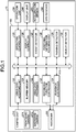
- FIG. 1 is a block diagram illustrating a configuration example of a vehicular recording apparatus that includes a vehicular recording control apparatus according to a first embodiment.
- a vehicular recording apparatus 10 appropriately monitors parking by use of at least one camera out of a plurality of cameras that is appropriate in accordance with the positional relation between a vehicle and a surrounding object.
- a surrounding object is an object present in the surroundings of the vehicle while the vehicle is parked.
- a surrounding object physically separates the surroundings of the vehicle.
- a surrounding object blocks entry of another vehicle into the surroundings of the vehicle.
- a surrounding object is, for example, a garage, a wall, a fence, a car stop, a step height, or another object that another vehicle cannot easily climb over.
- the vehicular recording apparatus 10 may be an apparatus fixedly mounted on the vehicle or may be a portable apparatus that can be used on the vehicle.
- the vehicular recording apparatus 10 may be implemented in such a manner as to include the function or the configuration of an apparatus previously installed on the vehicle or of a navigation apparatus.
- the vehicular recording apparatus 10 includes a camera unit (plurality of image capturing units) 210, a recorder 220, an operation unit 230, a display unit 240, an acceleration sensor 250, a global positioning system (GPS) receiver 260, and a vehicular recording control apparatus 100.
- GPS global positioning system
- the camera unit 210 includes a plurality of cameras that captures images of the surroundings of the vehicle. The individual cameras capture images in different directions from the vehicle.
- the camera unit 210 includes a frontward camera 211 enabled to capture images in the frontward direction and a rearward camera 212 enabled to capture images in the rearward direction.
- the frontward camera 211 is arranged in, for example, a relatively front part of the vehicle interior of the vehicle.
- the rearward camera 212 is arranged in, for example, a relatively rear part of the vehicle interior of the vehicle. The following description refers to the cameras as the camera unit 210 when there is no need to differentiate therebetween.
- the camera unit 210 is capable of saving video upon detection of an event while an accessory power supply is off, in other words, while the vehicle is in a parked state.
- the video corresponds to a certain period the length of which is, for example, about a few tens of seconds.
- the camera unit 210 outputs captured video data to a video data acquiring unit 120 in the vehicular recording control apparatus 100.
- the video data is, for example, moving images composed of images, the frame rate of which is 30 frames per second.
- the camera unit 210 Under the control of the vehicular recording control apparatus 100, the camera unit 210 actuates all or some of the cameras selected out of the cameras included in the camera unit 210 and outputs, to the video data acquiring unit 120, video data captured by the at least one camera thus actuated.
- the recorder 220 is used for, for example, temporarily storing data in the vehicular recording apparatus 10.
- the recorder 220 is a recorder such as a semiconductor memory device, the examples of which include a random access memory (RAM) and a flash memory, or a memory card.
- the recorder 220 may be an external recorder wirelessly connected via a communication apparatus not illustrated.
- the recorder 220 records therein loop-recorded video data or event recording data based on a control signal output from a recording function controller 123 in the vehicular recording control apparatus 100.
- the operation unit 230 is capable of receiving various operations performed on the vehicular recording apparatus 10.
- the operation unit 230 is capable of receiving an operation for manually saving, as event recording data, captured video data in the recorder 220.
- the operation unit 230 is capable of receiving an operation for playing back loop-recorded video data or event recording data recorded in the recorder 220.
- the operation unit 230 is capable of receiving an operation for deleting event recording data recorded in the recorder 220.
- the operation unit 230 is capable of receiving an operation for ending loop recording.
- the operation unit 230 outputs operational information to an operation controller 125 in the vehicular recording control apparatus 100.
- the display unit 240 is, as an example, a display apparatus dedicated to the vehicular recording apparatus 10 or a display apparatus shared with other systems including a navigation system.
- the display unit 240 may be formed integrally with the camera unit 210.
- the display unit 240 is, for example, a display including a liquid crystal display (LCD) or an organic electro-luminescence (EL) display.
- the display unit 240 is arranged on a dashboard, an instrument panel, or a center console in front of a driver in the front part of the vehicle.
- the display unit 240 displays video based on a video signal output from a display controller 126 in the vehicular recording control apparatus 100.
- the display unit 240 displays video that is being captured by the camera unit 210 or video that has been recorded in the recorder 220.
- the acceleration sensor 250 is a sensor that detects acceleration acting on the vehicle.
- the acceleration sensor 250 outputs a detection result to an event detector 127 in the vehicular recording control apparatus 100.
- the acceleration sensor 250 is, for example, a sensor that detects acceleration in triaxial directions.
- the triaxial directions are the frontward or rearward direction, the leftward or rightward direction, and the upward or downward direction of the vehicle.
- the GPS receiver 260 receives radio waves from a GPS satellite not illustrated.
- the GPS receiver 260 outputs a signal of a received radio wave to a positional information acquiring unit 128 in the vehicular recording control apparatus 100.
- the vehicular recording control apparatus 100 is, for example, an arithmetic processing unit (control apparatus) composed of components such as a central processing unit (CPU).
- the vehicular recording control apparatus 100 loads a stored computer program onto a memory and executes instructions contained in the computer program.
- the vehicular recording control apparatus 100 includes an internal memory not illustrated, and the internal memory is used for temporarily storing data in the vehicular recording control apparatus 100, for example.
- the vehicular recording control apparatus 100 includes the video data acquiring unit 120, a buffer memory 121, a video data processor 122, the recording function controller 123, a playback controller 124, the operation controller 125, the display controller 126, the event detector 127, the positional information acquiring unit 128, a parking detector 129, and an object detector 130, all connected to a bus 110.
- the video data acquiring unit 120 acquires video data obtained by capturing images of the surroundings of the vehicle. More specifically, the video data acquiring unit 120 acquires video data output by the camera unit 210 and outputs the video data to the buffer memory 121. The video data acquiring unit 120 acquires video data captured by all or some of the cameras selected and thus actuated out of the cameras included in the camera unit 210.
- the buffer memory 121 is an internal memory included in the vehicular recording control apparatus 100 and is a memory that temporarily records therein video data of a certain length of time acquired by the video data acquiring unit 120 while successively updates recorded video data.
- the video data processor 122 converts, into a desired file format, video data temporarily stored in the buffer memory 121.
- the desired file format is, for example, the MP4 format obtained through coding with a codec compliant with a desired method such as H.264 or Moving Picture Experts Group (MPEG)-4.
- the video data processor 122 generates, from video data temporarily stored in the buffer memory 121, video data segmented as files each corresponding to a certain length of time.
- the video data processor 122 generates, from video data temporarily stored in the buffer memory 121, video data segmented as files each corresponding to a time period of 60 seconds in chronological order of the recording.
- the video data processor 122 outputs the generated video data to the recording function controller 123.
- the video data processor 122 outputs the generated video data also to the display controller 126.
- the period to which video data generated as a file corresponds is described as 60 seconds as an example but is not limited to this example.
- Video data as used herein may be data that contains sound along with video captured by the camera unit 210.
- the recording function controller 123 performs control over recording in the recorder 220 of video data segmented as files by the video data processor 122. During a period in which loop recording is executed, such as a period in which the accessory power supply of the vehicle is on, the recording function controller 123 records video data segmented as files by the video data processor 122, as video data that can be overwritten, in the recorder 220. More specifically, during a period in which loop recording is executed, the recording function controller 123 continues to record, in the recorder 220, video data generated by the video data processor 122 and records new video data in such a manner as to overwrite the oldest video data therewith once the capacity of the recorder 220 is used up.
- the recording function controller 123 Upon detection of an event by the event detector 127, the recording function controller 123 saves video data corresponding to a certain period generated by the video data processor 122, as write-protected event recording data, in the recorder 220.
- saved as event recording data in the recorder 220 by the recording function controller 123 is video data for a certain period that is, for example, about not less than 10 seconds and not more than 60 seconds after the capturing is started upon the detection of the event.
- saved as event recording data in the recorder 220 by the recording function controller 123 is video data for a certain period that is about not less than 10 seconds and not more than 60 seconds, the center of which corresponds to the time when the event is detected.
- the recording function controller 123 puts a parking monitoring function into operation, thereby saving video data captured by the camera unit 210. More specifically, the parking monitoring function detects an event and saves video data through loop recording. Otherwise, the parking monitoring function actuates the camera unit 210 and then saves video data upon detection of an event.
- the recording function controller 123 controls the parking monitoring function in accordance with the positional relation between the vehicle and the surrounding object.
- the object detector 130 detects a surrounding object at a distance less than a certain distance from the vehicle while the vehicle is parked
- recording due to an event detected by the event detector 127 is performed by the recording function controller 123 using video data captured by a camera in the camera unit 210 other than a camera capturing images in a direction (hereinafter referred to as "surrounding object direction") in which the surrounding object is detected.
- a camera other than for the surrounding object direction means a camera that is included in the camera unit 210 and that captures images in a range of directions that include a direction other than the surrounding object direction.
- a camera other than for the surrounding object direction is the rearward camera 212, which captures images in a range of directions that include a direction other than the frontward direction.
- the recording function controller 123 when a surrounding object is detected at a distance less than the certain distance from the vehicle, the recording function controller 123 causes a camera other than a camera capturing images in the surrounding object direction in the camera unit 210 to capture video. Having a surrounding object present rules out the possibility that another vehicle may approach and collide with the vehicle along the surrounding object direction. The recording function controller 123 thus needs only to cause the camera other than for the surrounding object direction in the camera unit 210 to capture video. Based on detection of an event by the event detector 127, the recording function controller 123 then saves, as event recording data, video data captured by the camera other than for the surrounding object direction in the camera unit 210.
- the recording function controller 123 When having detected no surrounding object at a distance less than the certain distance from the vehicle, the recording function controller 123 causes all of the cameras in the camera unit 210 to capture video. With no surrounding object present, there is a possibility that another vehicle may approach and collide with the vehicle along any direction. It is therefore preferable that the recording function controller 123 cause all of the cameras to capture video. Based on detection of an event by the event detector 127, the recording function controller 123 then saves, as event recording data, video data captured by all of the cameras.
- the playback controller 124 Based on a control signal for a playback operation output from the operation controller 125, the playback controller 124 performs control so as to play back loop-recorded video data or event recording data recorded in the recorder 220.
- the operation controller 125 acquires operational information on an operation received by the operation unit 230. For example, the operation controller 125 outputs a control signal upon acquiring any one of the following: saving operation information indicating an operation for manually saving video data; playback operation information indicating a playback operation; and a deletion operation information indicating an operation for deleting video data. For example, the operation controller 125 outputs a control signal upon acquiring exit operation information indicating an operation for exiting loop recording.
- the display controller 126 controls displaying of video data on the display unit 240.
- the display controller 126 outputs a video signal that causes video data to be output to the display unit 240. More specifically, the display controller 126 outputs a video signal to be displayed by playing back video that the camera unit 210 is capturing or either loop-recorded video data or event recording data recorded in the recorder 220.
- the event detector 127 Based on a detection result from the acceleration sensor 250, the event detector 127 detects an event concerning the vehicle. More specifically, the event detector 127 detects, as an event, when acceleration of a magnitude not less than a threshold value is detected from acceleration detected by the acceleration sensor 250.
- the threshold value used for detecting an event while parking is recorded may be set smaller than a threshold value used for detecting an event while the vehicle travels. For example, when the threshold value for acceleration based on which an event is detected while the vehicle travels is, for example, about 1 G, the threshold value for acceleration based on which an event is detected while parking is recorded may be set to about 0.3 G.
- the positional information acquiring unit 128 calculates positional information on the vehicle using a publicly known method.
- a parking detector 129 Based on information acquired from the vehicle, a parking detector 129 detects whether the vehicle is in a parked state.
- That the vehicle is in a parked state indicates a state in which the shift position has been set to "parking", the parking brake has been activated, the speed has been zero, for example, at least 5 seconds, or the engine has been stopped.
- the vehicle may be determined to be in a parked state.
- the object detector 130 While the vehicle is parked, the object detector 130 detects a surrounding object that is present at a distance less than the certain distance from the vehicle at a position at which the vehicle is parked and that blocks entry of another vehicle.
- the certain distance is, for example, about 2 meters.
- the object detector 130 detects a direction from the vehicle in which the surrounding object is detected.
- the object detector 130 may, for example, output radio waves other than visible light toward the surroundings of the vehicle and detect an object based on a detection result from a sensor that detects an object using reflected waves of the radio waves.
- the object detector 130 may, for example, detect an object based on a detection result from an infrared sensor, an ultrasound sensor, or a millimeter-wave radar.
- the object detector 130 may, for example, detect an object by performing image processing on video data captured by the camera unit 210.
- the object detector 130 may, for example, detect an object based on the positional information acquired by the positional information acquiring unit 128 and map information acquired by the navigation system.
- the object detector 130 may be any desirable device capable of detecting an object.
- the vehicular recording apparatus 10 continuously records video to perform what is called loop recording and conducts event detection throughout a period from the start to stop of the engine, that is, while the vehicle is not in a parked state and is in operation. While the accessory power supply is off, in other words, while the vehicle is in a parked state, the vehicular recording apparatus 10 performs either of the following: continuous recording of video, that is, what is called loop recording, and event detection at the same time, provided that the vehicular recording apparatus 10 has power supplied to any other power supply than the accessory power supply from the battery of the vehicle; and event detection and video capturing upon detection of an event, provided that the vehicular recording apparatus 10 is being operated with a battery dedicated thereto.
- FIG. 2 is a flowchart illustrating the procedure of processing in the vehicular recording control apparatus according to the first embodiment.
- the vehicular recording control apparatus 100 determines, using the parking detector 129, whether the vehicle is in a parked state (step S11). If it is determined, using the parking detector 129, that the vehicle is in a parked state (Yes at step S11), the vehicular recording control apparatus 100 shifts the processing to step S12. If it is determined, using the parking detector 129, that the vehicle is not in a parked state (No at step S11), the vehicular recording control apparatus 100 ends the present processing. Before the determination results in Yes at step S11 in the processing of FIG. 2 , and after the processing of FIG. 2 ends, the vehicle is not in a parked state, and event detection intended for a period in which the vehicle travels is performed.
- the vehicular recording control apparatus 100 If it is determined that the vehicle is in a parked state (Yes at step S11), the vehicular recording control apparatus 100 puts the parking monitoring function into operation (step S12). The vehicular recording control apparatus 100 ends the present processing.
- FIG. 3 is a flowchart illustrating the procedure of processing in the vehicular recording control apparatus according to the first embodiment.
- video data corresponding to a certain period including, and before and after, a detection time point when the event is detected is saved as event detection data in the recorder 220 from video data that is being loop-recorded.
- FIG. 3 The processing of FIG. 3 is started by having the parking monitoring function put into operation at step S12 in the flowchart illustrated in FIG. 2 .
- the vehicular recording control apparatus 100 determines whether a surrounding object that blocks entry of another vehicle is present at a distance less than the certain distance from the vehicle (step S101). More specifically, if it is determined that a surrounding object that blocks entry of another vehicle is present (Yes at step S101) because a detection result from the object detector 130 indicates that a surrounding object that blocks entry of another vehicle is present at a distance less than the certain distance rom the vehicle, the vehicular recording control apparatus 100 shifts the processing to step S102.
- the object detection that the object detector 130 performs for the determination at step S101 may be based on a detection result immediately before the vehicle is parked or may be detected after the vehicle is parked.
- the vehicular recording control apparatus 100 shifts the processing to step S106.
- the vehicular recording control apparatus 100 If it is determined at step S101 that a surrounding object that blocks entry of another vehicle is present at a distance less than the certain distance from the vehicle (Yes at step S101), the vehicular recording control apparatus 100 starts continuous recording using a camera other than for the surrounding object direction in the camera unit 210 (step S102). More specifically, the vehicular recording control apparatus 100 starts event detection based on output from the acceleration sensor 250 at the same time as causing the recording function controller 123 to start loop recording using video data captured by the camera other than for the surrounding object direction (step S102) and shifts the processing to step S103.
- the vehicular recording control apparatus 100 determines whether acceleration of a rate not less than a threshold value has been detected (step S103). More specifically, if acceleration of a magnitude not less than the threshold value has been detected by the event detector 127, the vehicular recording control apparatus 100 determines that an event has been detected (Yes at step S103) and shifts the processing to step S104. If acceleration of a magnitude not less than the threshold value has not been detected by the event detector 127, the vehicular recording control apparatus 100 determines that an event has not been detected (No at step S103) and shifts the processing to step S105.
- the vehicular recording control apparatus 100 saves event recording data from video data captured by a camera other than for the surrounding object direction in the camera unit 210 (step S104). More specifically, the vehicular recording control apparatus 100 generates, as event recording data, video data that has been captured for a certain period including, and before and after, the event detection time point and that has been acquired by the video data processor 122 from the camera other than for the surrounding object direction. If it is determined that a certain length of time has passed, the vehicular recording control apparatus 100 causes the recording function controller 123 to save, in the recorder 220, the event recording data generated by the video data processor 122 and shifts the processing to step S105.
- the vehicular recording control apparatus 100 determines whether the parking monitoring function has been ended (step S105). Conditions that result in determination that the parking monitoring function has been ended include that the accessory power supply has been turned on and that the parking monitoring function has been stopped by the operation unit 230.
- step S105 If it is determined at step S105 that the parking monitoring function has been ended (Yes at step S105), the present processing is ended. If it is determined that the parking monitoring function has not been ended (No at step S105), the present processing is returned to step S103.
- the vehicular recording control apparatus 100 starts continuous recording using video data captured by all of the cameras in the camera unit 210 (step S106). More specifically, the vehicular recording control apparatus 100 starts event detection based on output from the acceleration sensor 250 at the same time as causing the recording function controller 123 to start loop recording using video data captured by all of the cameras in the camera unit 210 (step S106) and shifts the processing to step S107.
- step S107 the same processing as the processing at step S103 is performed.
- the vehicular recording control apparatus 100 saves event recording data from video data captured by all of the cameras in the camera unit 210 (step S108). More specifically, the vehicular recording control apparatus 100 generates, as event recording data, video data that has been captured for a certain period including, and before and after, the event detection time point and that has been acquired by the video data processor 122 from all of the cameras in the camera unit 210. If it is determined that a certain length of time has passed, the vehicular recording control apparatus 100 causes the recording function controller 123 to save, in the recorder 220, the event recording data generated by the video data processor 122 and shifts the processing to step S109.
- step S109 the same processing as the processing at step S105 is performed.
- FIG. 4 is a flowchart illustrating the procedure of processing in the vehicular recording control apparatus according to the first embodiment.
- the camera unit 210 is actuated based on event detection, and video data for a certain period after an event is detected is saved as event recording data in the recorder 220.
- FIG. 4 The processing of FIG. 4 is started by having the parking monitoring function put into operation at step S12 in the flowchart illustrated in FIG. 2 .
- the same processing as the processing at step S101, step S103, step S105, step S107, and step S109 in FIG. 3 is performed at step S111, step S112, step S115, step S116, and step S119 in FIG. 4 .
- the vehicular recording control apparatus 100 After determining that a surrounding object that blocks entry of another vehicle is present, if acceleration of a magnitude not less than a threshold value has been detected at step S112 (Yes at step S112), the vehicular recording control apparatus 100 causes the recording function controller 123 to start image capturing by a camera other than for the surrounding object direction in the camera unit 210 (step S113) and shifts the processing to step S114.
- the vehicular recording control apparatus 100 causes the recording function controller 123 to save video data captured by a camera other than for the surrounding object direction in the camera unit 210, as event recording data, in the recorder 220 (step S114) and shifts the processing to step S115.
- the event recording data saved at step S114 is video data corresponding to a period between when the image capturing is started at step S113 and when the recording is ended following determination that the certain period has passed.
- the vehicular recording control apparatus 100 After determining that no surrounding object that blocks entry of another vehicle is present, if acceleration of a magnitude not less than the threshold value has been detected at step S116 (Yes at step S116), the vehicular recording control apparatus 100 causes the recording function controller 123 to start image capturing by all of the cameras in the camera unit 210 (step S117) and shifts the processing to step S118.
- the vehicular recording control apparatus 100 causes the recording function controller 123 to save video data captured by all of the cameras in the camera unit 210, as event recording data, in the recorder 220 (step S118) and shifts the processing to step S119.
- the event recording data saved at step S118 is video data corresponding to a period between when the image capturing is started at step S117 and when the recording is ended following determination that the certain period has passed.
- the parking monitoring function is put into operation with the camera, other than for the surrounding object direction in the camera unit 210, capturing video.
- the parking monitoring function is put into operation with all of the cameras in the camera unit 210 capturing video.
- the parking monitoring function when a surrounding object that blocks entry of another vehicle into the surroundings of the vehicle is detected, the parking monitoring function can be put into operation with a camera, other than for the surrounding object direction in the camera unit 210, capturing video.
- the parking monitoring function when no surrounding object is detected, the parking monitoring function can be put into operation with all of the cameras in the camera unit 210 capturing video.
- parking can be appropriately monitored using an appropriate camera in the camera unit 210 in accordance with the positional relation between the vehicle and a surrounding object.
- the camera unit 210 does not capture images in the surrounding object direction, in other words, in a direction along which no other vehicle may possibly approach and collide with the vehicle. In the present embodiment, the camera unit 210 captures images in a direction other than the surrounding object direction, in other words, in a direction along which another vehicle may possibly approach and collide with the vehicle. In the present embodiment, upon detection of a surrounding object, only a camera enabled to capture video in a direction along which another vehicle may possibly approach is actuated. As a result, parking can be monitored with reduced power consumption and for a longer length of time.
- FIG. 5 is a flowchart illustrating the procedure of processing in a vehicular recording control apparatus according to a second embodiment.
- FIG. 6 is a flowchart illustrating the procedure of processing in a vehicular recording control apparatus according to the second embodiment.
- the vehicular recording apparatus 10 has the same basic configuration as the vehicular recording apparatus 10 in the first embodiment has. In the following description, the same constituent elements as those of the vehicular recording apparatus 10 are assigned the same reference signs. In the vehicular recording apparatus 10, processing in the event detector 127 and the object detector 130 is different from the corresponding processing in the first embodiment.
- a surrounding object is an object that blocks entry of a person into the surroundings of the vehicle.
- a surrounding object is, for example, a garage, a wall, a fence, or an object that a person cannot easily climb over.
- the event detector 127 detects, as an event, when a moving object in the surroundings of the vehicle is detected. More specifically, the event detector 127 detects the moving object by performing image processing on video data captured by the camera unit 210.
- a method to be used for detecting the moving object from video data may be any publicly known technique and is not particularly limited.
- a moving object is, for example, an object that moves such as a vehicle, a person, a falling object, or a flying object.
- the object detector 130 While the vehicle is parked, the object detector 130 detects a surrounding object that is present at a distance less than the certain distance from the vehicle at a position at which the vehicle is parked and that blocks entry of a person.
- FIG. 5 the procedure of processing for detecting an event and saving video data through loop recording is described using FIG. 5 as an example of the parking monitoring function.
- video data of a certain period including and before and after a detection time point when the event is detected is saved as event detection data in the recorder 220 from video data that is being loop-recorded.
- FIG. 5 The processing of FIG. 5 is started by having the parking monitoring function put into operation at step S12 in the flowchart illustrated in FIG. 2 .
- the same processing as the processing at step S104, step S105, step S108, and step S109 in FIG. 3 is performed at step S124, step S125, step S128, and step S129 in FIG. 5 .
- the vehicular recording control apparatus 100 determines whether any surrounding object that blocks entry of a person is present at a distance less than the certain distance from the vehicle (step S121). More specifically, if it is determined that a surrounding object that blocks entry of a person is present (Yes at step S121) because a detection result from the object detector 130 indicates that a surrounding object that blocks entry of a person is present, the vehicular recording control apparatus 100 shifts the processing to step S122.
- the object detection to be performed by the object detector 130 for the determination at step S121 may be based on a detection result immediately before the vehicle is parked or may be detected after the vehicle is parked.
- the vehicular recording control apparatus 100 shifts the processing to step S126.
- the vehicular recording control apparatus 100 starts detection of a moving object using a camera other than for the surrounding object direction in the camera unit 210 and continuous recording (step S122). More specifically, the vehicular recording control apparatus 100 starts event detection based on video data captured by the camera other than for the surrounding object direction at the same time as starting, using the recording function controller 123, loop recording with the camera other than for the surrounding object direction and shifts the processing to step S123.
- the vehicular recording control apparatus 100 determines whether a moving object has been detected (step S123). More specifically, if a moving object in the surroundings of the vehicle has been detected by the event detector 127, the vehicular recording control apparatus 100 determines that an event has been detected (Yes at step S123) and shifts the processing to step S124. If no moving object in the surroundings of the vehicle has been detected by the event detector 127, the vehicular recording control apparatus 100 determines that no event has been detected (No at step S123) and shifts the processing to step S125.
- the vehicular recording control apparatus 100 starts detection of a moving object using all of the cameras in the camera unit 210 and continuous recording (step S126). More specifically, the vehicular recording control apparatus 100 starts event detection based on video data captured by all of the cameras at the same time as causing the recording function controller 123 to perform loop recording with all of the cameras and shifts the processing to step S127.
- step S127 the same processing as the processing at step S123 is performed.
- FIG. 6 the procedure of processing for actuating a camera and saving video data after an event is detected is described using FIG. 6 as another example of the parking monitoring function.
- the camera unit 210 is actuated based on event detection, and video data for a certain period after an event is detected is saved as event recording data in the recorder 220.
- FIG. 6 The processing of FIG. 6 is started by having the parking monitoring function put into operation at step S12 in the flowchart illustrated in FIG. 2 .
- the same processing as the processing at step S121, step S123, step S125, step S127, and step S129 in FIG. 5 is performed at step S131, step S133, step S136, step S138, and step S141 in FIG. 6 .
- the same processing as the processing at step S114 and step S118 in FIG. 4 is performed at step S135 and step S140 in FIG. 6 .
- the vehicular recording control apparatus 100 causes the recording function controller 123 to start detection of a moving object using a camera other than for the surrounding object direction in the camera unit 210 (step S132) and shifts the processing to step S133.
- the vehicular recording control apparatus 100 causes the recording function controller 123 to start image capturing by a camera other than for the surrounding object direction in the camera unit 210 to (step S134) and shifts the processing to step S135.
- the vehicular recording control apparatus 100 causes the recording function controller 123 to start detection of a moving object using all of the cameras in the camera unit 210 (step S137) and shifts the processing to step S138.
- the vehicular recording control apparatus 100 causes the recording function controller 123 to start image capturing by all of the cameras in the camera unit 210 (step S139) and shifts the processing to step S140.
- the parking monitoring function when a surrounding object that blocks entry of a person into the surroundings of the vehicle is detected, the parking monitoring function can be put into operation with a camera, other than for the surrounding object direction in the camera unit 210, capturing video. In the present embodiment, when no surrounding object is detected, the parking monitoring function can be put into operation with all of the cameras in the camera unit 210 capturing video.
- the camera unit 210 does not capture images in the surrounding object direction, in other words, in a direction along which no person may possibly approach and collide with the vehicle. In the present embodiment, the camera unit 210 captures images in a direction other than the surrounding object direction, in other words, in a direction along which a person may possibly approach and collide with the vehicle. Thus, in the present embodiment, only a camera enabled to capture video in a direction along which a person may possibly approach is actuated when the parking monitoring function is put into operation. As a result, power consumption can be reduced.
- the vehicular recording apparatus 10 according to the present invention may be implemented in various different forms other than the above-described embodiments.
- the individual constituent elements of the vehicular recording apparatus 10 illustrated are functionally conceptual and does not necessarily need to be physically configured as illustrated. That is, specific forms of the individual apparatuses are not limited to those illustrated, and all or some of the individual apparatuses may be functionally or physically distributed or integrated in any desirable units in accordance with respective processing loads of the apparatuses and how the apparatuses are used.
- the configurations for the vehicular recording apparatus 10 are implemented, for example, as software, by forms such as computer programs loaded on memory.
- the configurations are described as functional blocks implemented by cooperation of these pieces of hardware or software. That is, these functional blocks can be implemented by any one of such various forms as only hardware, only software, and a combination of hardware and software.
Landscapes
- Engineering & Computer Science (AREA)
- Multimedia (AREA)
- Mechanical Engineering (AREA)
- Physics & Mathematics (AREA)
- General Physics & Mathematics (AREA)
- Signal Processing (AREA)
- Traffic Control Systems (AREA)
- Time Recorders, Dirve Recorders, Access Control (AREA)
- Closed-Circuit Television Systems (AREA)
Abstract
Description
- The present invention relates to a vehicular recording control apparatus, a vehicular recording apparatus, a vehicular recording control method, and a computer program.
- What is called a driving recorder (vehicular recording apparatus) that captures images in the frontward and rearward directions of a vehicle is known. A driving recorder includes a frontward camera that captures images in the frontward direction of a vehicle, and a rearward camera that captures images in the rearward direction of the vehicle (see, for example, Patent Literature 1). A driving recorder saves video from a frontward camera and from a rearward camera, as event recording data, upon detection of an event (see, for example, Patent Literature 2) .
-
- Patent Literature 1: Japanese Patent Application Laid-open No.
2014-044692 - Patent Literature 2: Japanese Patent Application Laid-open No.
2006-321357 - A driving recorder that monitors parking records an event when acceleration of a magnitude not less than a threshold value acts on a vehicle or when a moving object is detected. When parking is monitored using a driving recorder including a plurality of cameras such as a frontward camera and a rearward camera, power consumption is higher and a period for which parking can be monitored may possibly be shorter than when parking is monitored by use of a single camera. Furthermore, the size of video captured by the plurality of cameras is larger than the size of video captured when parking is monitored by use of a single camera. Therefore, an upper limit up to which video can be saved as event recording data may possibly be insufficient.
- The present invention has been made in view of the above inconveniences and is directed to appropriately monitoring parking.
- To solve the above problem and achieve the above object, a vehicular recording control apparatus according to the present invention comprising: a video data acquiring unit configured to acquire video data acquired by a plurality of image capturing units that capture images of surroundings of a vehicle; an event detector configured to detect an event concerning the vehicle; a parking detector configured to detect whether the vehicle is in a parked state; an object detector configured to detect a surrounding object present at a distance less than a certain distance from the vehicle while the vehicle is parked; and a recording function controller configured to, when the object detector detects a surrounding object present at a distance less than the certain distance from the vehicle while the vehicle is parked, perform recording due to the event detected by the event detector, on a recorder using video data captured by the image capturing unit, among the image capturing units, other than the image capturing unit that captures images in a direction in which the surrounding object is detected.
- A vehicular recording apparatus according to the present invention comprising: the vehicular recording control apparatus above; and both a plurality of image capturing units and a recorder or either thereof, the plurality of image capturing units being configured to capture images of the surroundings of the vehicle, the recorder being configured to record the video data.
- A vehicular recording control method according to the present invention comprising: a parking detecting step of detecting whether a vehicle is in a parked state; an object detecting step of detecting a surrounding object present at a distance less than a certain distance from the vehicle while the vehicle is parked; an event detecting step of detecting an event concerning the vehicle; and a recording function controlling step of performing, when a surrounding object present at a distance less than the certain distance from the vehicle is detected at the object detecting step while the vehicle is parked, recording due to the event detected at the event detecting step, using video data captured by an image capturing unit, among a plurality of image capturing units configured to capture images of surroundings of the vehicle, other than the image capturing unit that captures images in a direction in which the surrounding object is detected.
- A computer program according to the present invention causing a computer operating as a vehicular recording control apparatus to execute: a parking detecting step of detecting whether a vehicle is in a parked state; an object detecting step of detecting a surrounding object present at a distance less than a certain distance from the vehicle while the vehicle is parked; an event detecting step of detecting an event concerning the vehicle; and a recording function controlling step of performing, when a surrounding object present at a distance less than the certain distance from the vehicle is detected at the object detecting step while the vehicle is parked, recording due to the event detected at the event detecting step, using video data captured by an image capturing unit, among a plurality of image capturing units configured to capture images of surroundings of the vehicle, other than the image capturing unit that captures images in a direction in which the surrounding object is detected.
- According to the present invention, the effect of enabling appropriate monitoring of parking is produced.
-
-
FIG. 1 is a block diagram illustrating a configuration example of a vehicular recording apparatus that includes a vehicular recording control apparatus according to a first embodiment. -
FIG. 2 is a flowchart illustrating the procedure of processing in the vehicular recording control apparatus according to the first embodiment. -
FIG. 3 is a flowchart illustrating the procedure of processing in the vehicular recording control apparatus according to the first embodiment. -
FIG. 4 is a flowchart illustrating the procedure of processing in the vehicular recording control apparatus according to the first embodiment. -
FIG. 5 is a flowchart illustrating the procedure of processing in a vehicular recording control apparatus according to a second embodiment. -
FIG. 6 is a flowchart illustrating the procedure of processing in a vehicular recording control apparatus according to the second embodiment. - The following describes embodiments of a vehicular recording control apparatus, a vehicular recording apparatus, a vehicular recording control method, and a computer program according to the present invention in detail with reference to the accompanying drawings. The following embodiments are not intended to limit the present invention.
-
FIG. 1 is a block diagram illustrating a configuration example of a vehicular recording apparatus that includes a vehicular recording control apparatus according to a first embodiment. A vehicular recording apparatus 10 appropriately monitors parking by use of at least one camera out of a plurality of cameras that is appropriate in accordance with the positional relation between a vehicle and a surrounding object. - A surrounding object is an object present in the surroundings of the vehicle while the vehicle is parked. A surrounding object physically separates the surroundings of the vehicle. A surrounding object blocks entry of another vehicle into the surroundings of the vehicle. A surrounding object is, for example, a garage, a wall, a fence, a car stop, a step height, or another object that another vehicle cannot easily climb over.
- The vehicular recording apparatus 10 may be an apparatus fixedly mounted on the vehicle or may be a portable apparatus that can be used on the vehicle. The vehicular recording apparatus 10 may be implemented in such a manner as to include the function or the configuration of an apparatus previously installed on the vehicle or of a navigation apparatus. The vehicular recording apparatus 10 includes a camera unit (plurality of image capturing units) 210, a
recorder 220, anoperation unit 230, adisplay unit 240, anacceleration sensor 250, a global positioning system (GPS)receiver 260, and a vehicularrecording control apparatus 100. - The
camera unit 210 includes a plurality of cameras that captures images of the surroundings of the vehicle. The individual cameras capture images in different directions from the vehicle. In the present embodiment, thecamera unit 210 includes a frontward camera 211 enabled to capture images in the frontward direction and arearward camera 212 enabled to capture images in the rearward direction. The frontward camera 211 is arranged in, for example, a relatively front part of the vehicle interior of the vehicle. Therearward camera 212 is arranged in, for example, a relatively rear part of the vehicle interior of the vehicle. The following description refers to the cameras as thecamera unit 210 when there is no need to differentiate therebetween. In the present embodiment, thecamera unit 210 is capable of saving video upon detection of an event while an accessory power supply is off, in other words, while the vehicle is in a parked state. The video corresponds to a certain period the length of which is, for example, about a few tens of seconds. Thecamera unit 210 outputs captured video data to a videodata acquiring unit 120 in the vehicularrecording control apparatus 100. The video data is, for example, moving images composed of images, the frame rate of which is 30 frames per second. Under the control of the vehicularrecording control apparatus 100, thecamera unit 210 actuates all or some of the cameras selected out of the cameras included in thecamera unit 210 and outputs, to the videodata acquiring unit 120, video data captured by the at least one camera thus actuated. - The
recorder 220 is used for, for example, temporarily storing data in the vehicular recording apparatus 10. Therecorder 220 is a recorder such as a semiconductor memory device, the examples of which include a random access memory (RAM) and a flash memory, or a memory card. Alternatively, therecorder 220 may be an external recorder wirelessly connected via a communication apparatus not illustrated. Therecorder 220 records therein loop-recorded video data or event recording data based on a control signal output from arecording function controller 123 in the vehicularrecording control apparatus 100. - The
operation unit 230 is capable of receiving various operations performed on the vehicular recording apparatus 10. For example, theoperation unit 230 is capable of receiving an operation for manually saving, as event recording data, captured video data in therecorder 220. For example, theoperation unit 230 is capable of receiving an operation for playing back loop-recorded video data or event recording data recorded in therecorder 220. For example, theoperation unit 230 is capable of receiving an operation for deleting event recording data recorded in therecorder 220. For example, theoperation unit 230 is capable of receiving an operation for ending loop recording. Theoperation unit 230 outputs operational information to anoperation controller 125 in the vehicularrecording control apparatus 100. - The
display unit 240 is, as an example, a display apparatus dedicated to the vehicular recording apparatus 10 or a display apparatus shared with other systems including a navigation system. Thedisplay unit 240 may be formed integrally with thecamera unit 210. Thedisplay unit 240 is, for example, a display including a liquid crystal display (LCD) or an organic electro-luminescence (EL) display. In the present embodiment, thedisplay unit 240 is arranged on a dashboard, an instrument panel, or a center console in front of a driver in the front part of the vehicle. Thedisplay unit 240 displays video based on a video signal output from adisplay controller 126 in the vehicularrecording control apparatus 100. Thedisplay unit 240 displays video that is being captured by thecamera unit 210 or video that has been recorded in therecorder 220. - The
acceleration sensor 250 is a sensor that detects acceleration acting on the vehicle. Theacceleration sensor 250 outputs a detection result to anevent detector 127 in the vehicularrecording control apparatus 100. Theacceleration sensor 250 is, for example, a sensor that detects acceleration in triaxial directions. The triaxial directions are the frontward or rearward direction, the leftward or rightward direction, and the upward or downward direction of the vehicle. - The
GPS receiver 260 receives radio waves from a GPS satellite not illustrated. TheGPS receiver 260 outputs a signal of a received radio wave to a positionalinformation acquiring unit 128 in the vehicularrecording control apparatus 100. - The vehicular
recording control apparatus 100 is, for example, an arithmetic processing unit (control apparatus) composed of components such as a central processing unit (CPU). The vehicularrecording control apparatus 100 loads a stored computer program onto a memory and executes instructions contained in the computer program. The vehicularrecording control apparatus 100 includes an internal memory not illustrated, and the internal memory is used for temporarily storing data in the vehicularrecording control apparatus 100, for example. The vehicularrecording control apparatus 100 includes the videodata acquiring unit 120, abuffer memory 121, avideo data processor 122, therecording function controller 123, aplayback controller 124, theoperation controller 125, thedisplay controller 126, theevent detector 127, the positionalinformation acquiring unit 128, aparking detector 129, and anobject detector 130, all connected to abus 110. - The video
data acquiring unit 120 acquires video data obtained by capturing images of the surroundings of the vehicle. More specifically, the videodata acquiring unit 120 acquires video data output by thecamera unit 210 and outputs the video data to thebuffer memory 121. The videodata acquiring unit 120 acquires video data captured by all or some of the cameras selected and thus actuated out of the cameras included in thecamera unit 210. - The
buffer memory 121 is an internal memory included in the vehicularrecording control apparatus 100 and is a memory that temporarily records therein video data of a certain length of time acquired by the videodata acquiring unit 120 while successively updates recorded video data. - The
video data processor 122 converts, into a desired file format, video data temporarily stored in thebuffer memory 121. The desired file format is, for example, the MP4 format obtained through coding with a codec compliant with a desired method such as H.264 or Moving Picture Experts Group (MPEG)-4. Thevideo data processor 122 generates, from video data temporarily stored in thebuffer memory 121, video data segmented as files each corresponding to a certain length of time. As a specific example, thevideo data processor 122 generates, from video data temporarily stored in thebuffer memory 121, video data segmented as files each corresponding to a time period of 60 seconds in chronological order of the recording. Thevideo data processor 122 outputs the generated video data to therecording function controller 123. Thevideo data processor 122 outputs the generated video data also to thedisplay controller 126. The period to which video data generated as a file corresponds is described as 60 seconds as an example but is not limited to this example. Video data as used herein may be data that contains sound along with video captured by thecamera unit 210. - The
recording function controller 123 performs control over recording in therecorder 220 of video data segmented as files by thevideo data processor 122. During a period in which loop recording is executed, such as a period in which the accessory power supply of the vehicle is on, therecording function controller 123 records video data segmented as files by thevideo data processor 122, as video data that can be overwritten, in therecorder 220. More specifically, during a period in which loop recording is executed, therecording function controller 123 continues to record, in therecorder 220, video data generated by thevideo data processor 122 and records new video data in such a manner as to overwrite the oldest video data therewith once the capacity of therecorder 220 is used up. - Upon detection of an event by the
event detector 127, therecording function controller 123 saves video data corresponding to a certain period generated by thevideo data processor 122, as write-protected event recording data, in therecorder 220. - When capturing of video is started upon detection of an event, saved as event recording data in the
recorder 220 by therecording function controller 123 is video data for a certain period that is, for example, about not less than 10 seconds and not more than 60 seconds after the capturing is started upon the detection of the event. During a period in which loop recording is executed, saved as event recording data in therecorder 220 by therecording function controller 123 is video data for a certain period that is about not less than 10 seconds and not more than 60 seconds, the center of which corresponds to the time when the event is detected. - While the accessory power supply of the vehicle is off, in other words, while the vehicle is in a parked state, the
recording function controller 123 puts a parking monitoring function into operation, thereby saving video data captured by thecamera unit 210. More specifically, the parking monitoring function detects an event and saves video data through loop recording. Otherwise, the parking monitoring function actuates thecamera unit 210 and then saves video data upon detection of an event. - The
recording function controller 123 controls the parking monitoring function in accordance with the positional relation between the vehicle and the surrounding object. When theobject detector 130 detects a surrounding object at a distance less than a certain distance from the vehicle while the vehicle is parked, recording due to an event detected by theevent detector 127 is performed by therecording function controller 123 using video data captured by a camera in thecamera unit 210 other than a camera capturing images in a direction (hereinafter referred to as "surrounding object direction") in which the surrounding object is detected. - A camera other than for the surrounding object direction means a camera that is included in the
camera unit 210 and that captures images in a range of directions that include a direction other than the surrounding object direction. For example, when the surrounding object direction is the frontward direction of the vehicle, a camera other than for the surrounding object direction is therearward camera 212, which captures images in a range of directions that include a direction other than the frontward direction. - More specifically, when a surrounding object is detected at a distance less than the certain distance from the vehicle, the
recording function controller 123 causes a camera other than a camera capturing images in the surrounding object direction in thecamera unit 210 to capture video. Having a surrounding object present rules out the possibility that another vehicle may approach and collide with the vehicle along the surrounding object direction. Therecording function controller 123 thus needs only to cause the camera other than for the surrounding object direction in thecamera unit 210 to capture video. Based on detection of an event by theevent detector 127, therecording function controller 123 then saves, as event recording data, video data captured by the camera other than for the surrounding object direction in thecamera unit 210. - When having detected no surrounding object at a distance less than the certain distance from the vehicle, the
recording function controller 123 causes all of the cameras in thecamera unit 210 to capture video. With no surrounding object present, there is a possibility that another vehicle may approach and collide with the vehicle along any direction. It is therefore preferable that therecording function controller 123 cause all of the cameras to capture video. Based on detection of an event by theevent detector 127, therecording function controller 123 then saves, as event recording data, video data captured by all of the cameras. - Based on a control signal for a playback operation output from the
operation controller 125, theplayback controller 124 performs control so as to play back loop-recorded video data or event recording data recorded in therecorder 220. - The
operation controller 125 acquires operational information on an operation received by theoperation unit 230. For example, theoperation controller 125 outputs a control signal upon acquiring any one of the following: saving operation information indicating an operation for manually saving video data; playback operation information indicating a playback operation; and a deletion operation information indicating an operation for deleting video data. For example, theoperation controller 125 outputs a control signal upon acquiring exit operation information indicating an operation for exiting loop recording. - The
display controller 126 controls displaying of video data on thedisplay unit 240. Thedisplay controller 126 outputs a video signal that causes video data to be output to thedisplay unit 240. More specifically, thedisplay controller 126 outputs a video signal to be displayed by playing back video that thecamera unit 210 is capturing or either loop-recorded video data or event recording data recorded in therecorder 220. - Based on a detection result from the
acceleration sensor 250, theevent detector 127 detects an event concerning the vehicle. More specifically, theevent detector 127 detects, as an event, when acceleration of a magnitude not less than a threshold value is detected from acceleration detected by theacceleration sensor 250. The threshold value used for detecting an event while parking is recorded may be set smaller than a threshold value used for detecting an event while the vehicle travels. For example, when the threshold value for acceleration based on which an event is detected while the vehicle travels is, for example, about 1 G, the threshold value for acceleration based on which an event is detected while parking is recorded may be set to about 0.3 G. - Based on radio waves received by the
GPS receiver 260, the positionalinformation acquiring unit 128 calculates positional information on the vehicle using a publicly known method. - Based on information acquired from the vehicle, a
parking detector 129 detects whether the vehicle is in a parked state. - That the vehicle is in a parked state indicates a state in which the shift position has been set to "parking", the parking brake has been activated, the speed has been zero, for example, at least 5 seconds, or the engine has been stopped. In addition, when a desired trigger such as a user operation takes place, the vehicle may be determined to be in a parked state.
- While the vehicle is parked, the
object detector 130 detects a surrounding object that is present at a distance less than the certain distance from the vehicle at a position at which the vehicle is parked and that blocks entry of another vehicle. The certain distance is, for example, about 2 meters. Theobject detector 130 detects a direction from the vehicle in which the surrounding object is detected. - The
object detector 130 may, for example, output radio waves other than visible light toward the surroundings of the vehicle and detect an object based on a detection result from a sensor that detects an object using reflected waves of the radio waves. Theobject detector 130 may, for example, detect an object based on a detection result from an infrared sensor, an ultrasound sensor, or a millimeter-wave radar. Theobject detector 130 may, for example, detect an object by performing image processing on video data captured by thecamera unit 210. Theobject detector 130 may, for example, detect an object based on the positional information acquired by the positionalinformation acquiring unit 128 and map information acquired by the navigation system. Theobject detector 130 may be any desirable device capable of detecting an object. - The vehicular recording apparatus 10 continuously records video to perform what is called loop recording and conducts event detection throughout a period from the start to stop of the engine, that is, while the vehicle is not in a parked state and is in operation. While the accessory power supply is off, in other words, while the vehicle is in a parked state, the vehicular recording apparatus 10 performs either of the following: continuous recording of video, that is, what is called loop recording, and event detection at the same time, provided that the vehicular recording apparatus 10 has power supplied to any other power supply than the accessory power supply from the battery of the vehicle; and event detection and video capturing upon detection of an event, provided that the vehicular recording apparatus 10 is being operated with a battery dedicated thereto.
- Next, the procedure of processing in the vehicular
recording control apparatus 100 is described usingFIG. 2. FIG. 2 is a flowchart illustrating the procedure of processing in the vehicular recording control apparatus according to the first embodiment. - The vehicular
recording control apparatus 100 determines, using theparking detector 129, whether the vehicle is in a parked state (step S11). If it is determined, using theparking detector 129, that the vehicle is in a parked state (Yes at step S11), the vehicularrecording control apparatus 100 shifts the processing to step S12. If it is determined, using theparking detector 129, that the vehicle is not in a parked state (No at step S11), the vehicularrecording control apparatus 100 ends the present processing. Before the determination results in Yes at step S11 in the processing ofFIG. 2 , and after the processing ofFIG. 2 ends, the vehicle is not in a parked state, and event detection intended for a period in which the vehicle travels is performed. - If it is determined that the vehicle is in a parked state (Yes at step S11), the vehicular
recording control apparatus 100 puts the parking monitoring function into operation (step S12). The vehicularrecording control apparatus 100 ends the present processing. - Next, the procedure of processing for detecting an event and saving video data through loop recording is described using
FIG. 3 as an example of the parking monitoring function.FIG. 3 is a flowchart illustrating the procedure of processing in the vehicular recording control apparatus according to the first embodiment. In the processing illustrated inFIG. 3 , based on event detection, video data corresponding to a certain period including, and before and after, a detection time point when the event is detected is saved as event detection data in therecorder 220 from video data that is being loop-recorded. - The processing of
FIG. 3 is started by having the parking monitoring function put into operation at step S12 in the flowchart illustrated inFIG. 2 . - The vehicular
recording control apparatus 100 determines whether a surrounding object that blocks entry of another vehicle is present at a distance less than the certain distance from the vehicle (step S101). More specifically, if it is determined that a surrounding object that blocks entry of another vehicle is present (Yes at step S101) because a detection result from theobject detector 130 indicates that a surrounding object that blocks entry of another vehicle is present at a distance less than the certain distance rom the vehicle, the vehicularrecording control apparatus 100 shifts the processing to step S102. The object detection that theobject detector 130 performs for the determination at step S101 may be based on a detection result immediately before the vehicle is parked or may be detected after the vehicle is parked. If it is not determined that a surrounding object that blocks entry of another vehicle is present (No at step S101) because a detection result from theobject detector 130 does not indicate that a surrounding object that blocks entry of another vehicle is present at a distance less than the certain distance from the vehicle, the vehicularrecording control apparatus 100 shifts the processing to step S106. - If it is determined at step S101 that a surrounding object that blocks entry of another vehicle is present at a distance less than the certain distance from the vehicle (Yes at step S101), the vehicular
recording control apparatus 100 starts continuous recording using a camera other than for the surrounding object direction in the camera unit 210 (step S102). More specifically, the vehicularrecording control apparatus 100 starts event detection based on output from theacceleration sensor 250 at the same time as causing therecording function controller 123 to start loop recording using video data captured by the camera other than for the surrounding object direction (step S102) and shifts the processing to step S103. - The vehicular
recording control apparatus 100 determines whether acceleration of a rate not less than a threshold value has been detected (step S103). More specifically, if acceleration of a magnitude not less than the threshold value has been detected by theevent detector 127, the vehicularrecording control apparatus 100 determines that an event has been detected (Yes at step S103) and shifts the processing to step S104. If acceleration of a magnitude not less than the threshold value has not been detected by theevent detector 127, the vehicularrecording control apparatus 100 determines that an event has not been detected (No at step S103) and shifts the processing to step S105. - If acceleration of a magnitude not less than a threshold value has been detected (Yes at step S103), the vehicular
recording control apparatus 100 saves event recording data from video data captured by a camera other than for the surrounding object direction in the camera unit 210 (step S104). More specifically, the vehicularrecording control apparatus 100 generates, as event recording data, video data that has been captured for a certain period including, and before and after, the event detection time point and that has been acquired by thevideo data processor 122 from the camera other than for the surrounding object direction. If it is determined that a certain length of time has passed, the vehicularrecording control apparatus 100 causes therecording function controller 123 to save, in therecorder 220, the event recording data generated by thevideo data processor 122 and shifts the processing to step S105. - The vehicular
recording control apparatus 100 determines whether the parking monitoring function has been ended (step S105). Conditions that result in determination that the parking monitoring function has been ended include that the accessory power supply has been turned on and that the parking monitoring function has been stopped by theoperation unit 230. - If it is determined at step S105 that the parking monitoring function has been ended (Yes at step S105), the present processing is ended. If it is determined that the parking monitoring function has not been ended (No at step S105), the present processing is returned to step S103.
- If it is not determined at step S101 that a surrounding object that blocks entry of another vehicle is present at a distance less than the certain distance from the vehicle (No at step S101), the vehicular
recording control apparatus 100 starts continuous recording using video data captured by all of the cameras in the camera unit 210 (step S106). More specifically, the vehicularrecording control apparatus 100 starts event detection based on output from theacceleration sensor 250 at the same time as causing therecording function controller 123 to start loop recording using video data captured by all of the cameras in the camera unit 210 (step S106) and shifts the processing to step S107. - At step S107, the same processing as the processing at step S103 is performed.
- If acceleration of a magnitude not less than a threshold value has been detected at step S107 (Yes at step S107), the vehicular
recording control apparatus 100 saves event recording data from video data captured by all of the cameras in the camera unit 210 (step S108). More specifically, the vehicularrecording control apparatus 100 generates, as event recording data, video data that has been captured for a certain period including, and before and after, the event detection time point and that has been acquired by thevideo data processor 122 from all of the cameras in thecamera unit 210. If it is determined that a certain length of time has passed, the vehicularrecording control apparatus 100 causes therecording function controller 123 to save, in therecorder 220, the event recording data generated by thevideo data processor 122 and shifts the processing to step S109. - At step S109, the same processing as the processing at step S105 is performed.
- Next, the procedure of processing for actuating a camera and saving video data after an event is detected is described using
FIG. 4 as another example of the parking monitoring function.FIG. 4 is a flowchart illustrating the procedure of processing in the vehicular recording control apparatus according to the first embodiment. In the processing illustrated inFIG. 4 , thecamera unit 210 is actuated based on event detection, and video data for a certain period after an event is detected is saved as event recording data in therecorder 220. - The processing of
FIG. 4 is started by having the parking monitoring function put into operation at step S12 in the flowchart illustrated inFIG. 2 . The same processing as the processing at step S101, step S103, step S105, step S107, and step S109 inFIG. 3 is performed at step S111, step S112, step S115, step S116, and step S119 inFIG. 4 . - After determining that a surrounding object that blocks entry of another vehicle is present, if acceleration of a magnitude not less than a threshold value has been detected at step S112 (Yes at step S112), the vehicular
recording control apparatus 100 causes therecording function controller 123 to start image capturing by a camera other than for the surrounding object direction in the camera unit 210 (step S113) and shifts the processing to step S114. - The vehicular
recording control apparatus 100 causes therecording function controller 123 to save video data captured by a camera other than for the surrounding object direction in thecamera unit 210, as event recording data, in the recorder 220 (step S114) and shifts the processing to step S115. The event recording data saved at step S114 is video data corresponding to a period between when the image capturing is started at step S113 and when the recording is ended following determination that the certain period has passed. - After determining that no surrounding object that blocks entry of another vehicle is present, if acceleration of a magnitude not less than the threshold value has been detected at step S116 (Yes at step S116), the vehicular
recording control apparatus 100 causes therecording function controller 123 to start image capturing by all of the cameras in the camera unit 210 (step S117) and shifts the processing to step S118. - The vehicular
recording control apparatus 100 causes therecording function controller 123 to save video data captured by all of the cameras in thecamera unit 210, as event recording data, in the recorder 220 (step S118) and shifts the processing to step S119. The event recording data saved at step S118 is video data corresponding to a period between when the image capturing is started at step S117 and when the recording is ended following determination that the certain period has passed. - Thus, when a surrounding object that blocks entry of another vehicle into the surroundings of the vehicle is detected, the parking monitoring function is put into operation with the camera, other than for the surrounding object direction in the
camera unit 210, capturing video. When no surrounding object is detected, the parking monitoring function is put into operation with all of the cameras in thecamera unit 210 capturing video. - As described above, in the present embodiment, when a surrounding object that blocks entry of another vehicle into the surroundings of the vehicle is detected, the parking monitoring function can be put into operation with a camera, other than for the surrounding object direction in the
camera unit 210, capturing video. In the present embodiment, when no surrounding object is detected, the parking monitoring function can be put into operation with all of the cameras in thecamera unit 210 capturing video. According to the present embodiment, parking can be appropriately monitored using an appropriate camera in thecamera unit 210 in accordance with the positional relation between the vehicle and a surrounding object. - In the present embodiment, the
camera unit 210 does not capture images in the surrounding object direction, in other words, in a direction along which no other vehicle may possibly approach and collide with the vehicle. In the present embodiment, thecamera unit 210 captures images in a direction other than the surrounding object direction, in other words, in a direction along which another vehicle may possibly approach and collide with the vehicle. In the present embodiment, upon detection of a surrounding object, only a camera enabled to capture video in a direction along which another vehicle may possibly approach is actuated. As a result, parking can be monitored with reduced power consumption and for a longer length of time. - In the present embodiment, only a camera enabled to capture video in a direction along which another vehicle may possibly approach and collide is caused to operate, and video is then saved. As a result, the size of video data to be saved in the
recorder 220 can be reduced. - The vehicular recording apparatus 10 according to the present embodiment is described with reference to
FIG. 5 andFIG. 6 .FIG. 5 is a flowchart illustrating the procedure of processing in a vehicular recording control apparatus according to a second embodiment.FIG. 6 is a flowchart illustrating the procedure of processing in a vehicular recording control apparatus according to the second embodiment. The vehicular recording apparatus 10 has the same basic configuration as the vehicular recording apparatus 10 in the first embodiment has. In the following description, the same constituent elements as those of the vehicular recording apparatus 10 are assigned the same reference signs. In the vehicular recording apparatus 10, processing in theevent detector 127 and theobject detector 130 is different from the corresponding processing in the first embodiment. - In the present embodiment, a surrounding object is an object that blocks entry of a person into the surroundings of the vehicle. A surrounding object is, for example, a garage, a wall, a fence, or an object that a person cannot easily climb over.
- The
event detector 127 detects, as an event, when a moving object in the surroundings of the vehicle is detected. More specifically, theevent detector 127 detects the moving object by performing image processing on video data captured by thecamera unit 210. A method to be used for detecting the moving object from video data may be any publicly known technique and is not particularly limited. - A moving object is, for example, an object that moves such as a vehicle, a person, a falling object, or a flying object.
- While the vehicle is parked, the
object detector 130 detects a surrounding object that is present at a distance less than the certain distance from the vehicle at a position at which the vehicle is parked and that blocks entry of a person. - Next, the procedure of processing for detecting an event and saving video data through loop recording is described using
FIG. 5 as an example of the parking monitoring function. In the processing illustrated inFIG. 5 , based on event detection, video data of a certain period including and before and after a detection time point when the event is detected is saved as event detection data in therecorder 220 from video data that is being loop-recorded. - The processing of
FIG. 5 is started by having the parking monitoring function put into operation at step S12 in the flowchart illustrated inFIG. 2 . The same processing as the processing at step S104, step S105, step S108, and step S109 inFIG. 3 is performed at step S124, step S125, step S128, and step S129 inFIG. 5 . - The vehicular
recording control apparatus 100 determines whether any surrounding object that blocks entry of a person is present at a distance less than the certain distance from the vehicle (step S121). More specifically, if it is determined that a surrounding object that blocks entry of a person is present (Yes at step S121) because a detection result from theobject detector 130 indicates that a surrounding object that blocks entry of a person is present, the vehicularrecording control apparatus 100 shifts the processing to step S122. The object detection to be performed by theobject detector 130 for the determination at step S121 may be based on a detection result immediately before the vehicle is parked or may be detected after the vehicle is parked. If it is not determined that a surrounding object that blocks entry of a person is present (No at step S121) because a detection result from theobject detector 130 does not indicate that any surrounding object that blocks entry of a person is present, the vehicularrecording control apparatus 100 shifts the processing to step S126. - If, at step S121, any surrounding object that blocks entry of a person is determined to be present at a distance less than a certain distance from the vehicle (Yes at step S121), the vehicular
recording control apparatus 100 starts detection of a moving object using a camera other than for the surrounding object direction in thecamera unit 210 and continuous recording (step S122). More specifically, the vehicularrecording control apparatus 100 starts event detection based on video data captured by the camera other than for the surrounding object direction at the same time as starting, using therecording function controller 123, loop recording with the camera other than for the surrounding object direction and shifts the processing to step S123. - The vehicular
recording control apparatus 100 determines whether a moving object has been detected (step S123). More specifically, if a moving object in the surroundings of the vehicle has been detected by theevent detector 127, the vehicularrecording control apparatus 100 determines that an event has been detected (Yes at step S123) and shifts the processing to step S124. If no moving object in the surroundings of the vehicle has been detected by theevent detector 127, the vehicularrecording control apparatus 100 determines that no event has been detected (No at step S123) and shifts the processing to step S125. - If it is not determined at step S121 that a surrounding object that blocks entry of a person is present at a distance less than the certain distance from the vehicle (No at step S121), the vehicular
recording control apparatus 100 starts detection of a moving object using all of the cameras in thecamera unit 210 and continuous recording (step S126). More specifically, the vehicularrecording control apparatus 100 starts event detection based on video data captured by all of the cameras at the same time as causing therecording function controller 123 to perform loop recording with all of the cameras and shifts the processing to step S127. - At step S127, the same processing as the processing at step S123 is performed.
- Next, the procedure of processing for actuating a camera and saving video data after an event is detected is described using
FIG. 6 as another example of the parking monitoring function. In the processing illustrated inFIG. 6 , thecamera unit 210 is actuated based on event detection, and video data for a certain period after an event is detected is saved as event recording data in therecorder 220. - The processing of
FIG. 6 is started by having the parking monitoring function put into operation at step S12 in the flowchart illustrated inFIG. 2 . The same processing as the processing at step S121, step S123, step S125, step S127, and step S129 inFIG. 5 is performed at step S131, step S133, step S136, step S138, and step S141 inFIG. 6 . The same processing as the processing at step S114 and step S118 inFIG. 4 is performed at step S135 and step S140 inFIG. 6 . - If it is determined at step S131 that a surrounding object that blocks entry of a person is present at a distance less than the certain distance from the vehicle (Yes at step S131), the vehicular
recording control apparatus 100 causes therecording function controller 123 to start detection of a moving object using a camera other than for the surrounding object direction in the camera unit 210 (step S132) and shifts the processing to step S133. - If it is determined that a moving object surrounding the vehicle is present (Yes at step S133), the vehicular
recording control apparatus 100 causes therecording function controller 123 to start image capturing by a camera other than for the surrounding object direction in thecamera unit 210 to (step S134) and shifts the processing to step S135. - If it is determined at step S131 that no surrounding object that blocks entry of a person is present at a distance less than the certain distance from the vehicle (No at step S131), the vehicular
recording control apparatus 100 causes therecording function controller 123 to start detection of a moving object using all of the cameras in the camera unit 210 (step S137) and shifts the processing to step S138. - If a moving object surrounding the vehicle has been detected (Yes at step S138), the vehicular
recording control apparatus 100 causes therecording function controller 123 to start image capturing by all of the cameras in the camera unit 210 (step S139) and shifts the processing to step S140. - As described above, in the present embodiment, when a surrounding object that blocks entry of a person into the surroundings of the vehicle is detected, the parking monitoring function can be put into operation with a camera, other than for the surrounding object direction in the
camera unit 210, capturing video. In the present embodiment, when no surrounding object is detected, the parking monitoring function can be put into operation with all of the cameras in thecamera unit 210 capturing video. - In the present embodiment, the
camera unit 210 does not capture images in the surrounding object direction, in other words, in a direction along which no person may possibly approach and collide with the vehicle. In the present embodiment, thecamera unit 210 captures images in a direction other than the surrounding object direction, in other words, in a direction along which a person may possibly approach and collide with the vehicle. Thus, in the present embodiment, only a camera enabled to capture video in a direction along which a person may possibly approach is actuated when the parking monitoring function is put into operation. As a result, power consumption can be reduced. - In the present embodiment, only a camera enabled to capture video in a direction along which a person may possibly approach is actuated, and video is then saved. As a result, the size of video data to be saved in the
recorder 220 can be reduced. - The vehicular recording apparatus 10 according to the present invention may be implemented in various different forms other than the above-described embodiments.
- The individual constituent elements of the vehicular recording apparatus 10 illustrated are functionally conceptual and does not necessarily need to be physically configured as illustrated. That is, specific forms of the individual apparatuses are not limited to those illustrated, and all or some of the individual apparatuses may be functionally or physically distributed or integrated in any desirable units in accordance with respective processing loads of the apparatuses and how the apparatuses are used.
- The configurations for the vehicular recording apparatus 10 are implemented, for example, as software, by forms such as computer programs loaded on memory. In the above embodiments, the configurations are described as functional blocks implemented by cooperation of these pieces of hardware or software. That is, these functional blocks can be implemented by any one of such various forms as only hardware, only software, and a combination of hardware and software.
- The above constituent elements include those easily conceivable by the skilled person and those substantially identical with each other. The above configurations can be combined as appropriate. Various omissions, substitution and changes in the configurations can be made without departing from the spirit of the present invention.
-
- 10 VEHICULAR RECORDING APPARATUS
- 100 VEHICULAR RECORDING CONTROL APPARATUS
- 110 BUS
- 120 VIDEO DATA ACQUIRING UNIT
- 121 BUFFER MEMORY
- 122 VIDEO DATA PROCESSOR
- 123 RECORDING FUNCTION CONTROLLER (RECORDING CONTROLLER)
- 124 PLAYBACK CONTROLLER
- 125 OPERATION CONTROLLER
- 126 DISPLAY CONTROLLER
- 127 EVENT DETECTOR
- 128 POSITIONAL INFORMATION ACQUIRING UNIT
- 129 PARKING DETECTOR
- 130 OBJECT DETECTOR
- 210 CAMERA UNIT (PLURALITY OF IMAGE CAPTURING UNITS)
- 220 RECORDER
- 230 OPERATION UNIT
- 240 DISPLAY UNIT
- 250 ACCELERATION SENSOR
- 260 GPS RECEIVER
Claims (8)
- A vehicular recording control apparatus comprising:a video data acquiring unit configured to acquire video data acquired by a plurality of image capturing units that capture images of surroundings of a vehicle;an event detector configured to detect an event concerning the vehicle;a parking detector configured to detect whether the vehicle is in a parked state;an object detector configured to detect a surrounding object present at a distance less than a certain distance from the vehicle while the vehicle is parked; anda recording function controller configured to, when the object detector detects a surrounding object present at a distance less than the certain distance from the vehicle while the vehicle is parked, perform recording due to the event detected by the event detector, on a recorder using video data captured by the image capturing unit, among the image capturing units, other than the image capturing unit that captures images in a direction in which the surrounding object is detected.
- The vehicular recording control apparatus according to claim 1, wherein the object detector detects a surrounding object that blocks entry of another vehicle, the surrounding object being present at a distance less than the certain distance from the vehicle at a position at which the vehicle is parked.
- The vehicular recording control apparatus according to claim 2, wherein
the event detector detects, as the event, when acceleration of a magnitude not less than a certain magnitude acts on the vehicle, and
based on the detection of the event, the recording function controller saves, as event recording data, video data captured by the image capturing unit, among the image capturing units, other than the image capturing unit that captures images in a direction in which the surrounding object is detected. - The vehicular recording control apparatus according to claim 1, wherein the object detector detects a surrounding object that blocks entry of a person, the surrounding object being present at a distance less than the certain distance from the vehicle at a position at which the vehicle is parked.
- The vehicular recording control apparatus according to claim 4, wherein
the event detector detects, as the event, when a moving object in the surroundings of the vehicle is detected, and
based on the detection of the event, the recording function controller saves, as event recording data, video data captured by the image capturing unit, among the image capturing units, other than the image capturing unit that captures images in a direction in which the surrounding object is detected. - A vehicular recording apparatus comprising:the vehicular recording control apparatus according to any one of claims 1 to 5; andboth a plurality of image capturing units and a recorder or either thereof, the plurality of image capturing units being configured to capture images of the surroundings of the vehicle, the recorder being configured to record the video data.
- A vehicular recording control method comprising:a parking detecting step of detecting whether a vehicle is in a parked state;an object detecting step of detecting a surrounding object present at a distance less than a certain distance from the vehicle while the vehicle is parked;an event detecting step of detecting an event concerning the vehicle; anda recording function controlling step of performing, when a surrounding object present at a distance less than the certain distance from the vehicle is detected at the object detecting step while the vehicle is parked, recording due to the event detected at the event detecting step, using video data captured by an image capturing unit, among a plurality of image capturing units configured to capture images of surroundings of the vehicle, other than the image capturing unit that captures images in a direction in which the surrounding object is detected.
- A computer program causing a computer operating as a vehicular recording control apparatus to execute:a parking detecting step of detecting whether a vehicle is in a parked state;an object detecting step of detecting a surrounding object present at a distance less than a certain distance from the vehicle while the vehicle is parked;an event detecting step of detecting an event concerning the vehicle; anda recording function controlling step of performing, when a surrounding object present at a distance less than the certain distance from the vehicle is detected at the object detecting step while the vehicle is parked, recording due to the event detected at the event detecting step, using video data captured by an image capturing unit, among a plurality of image capturing units configured to capture images of surroundings of the vehicle, other than the image capturing unit that captures images in a direction in which the surrounding object is detected.
Applications Claiming Priority (2)
| Application Number | Priority Date | Filing Date | Title |
|---|---|---|---|
| JP2018243050A JP6696558B1 (en) | 2018-12-26 | 2018-12-26 | Vehicle recording control device, vehicle recording device, vehicle recording control method, and program |
| PCT/JP2019/023036 WO2020136941A1 (en) | 2018-12-26 | 2019-06-11 | Vehicle recording control device, vehicle recording device, vehicle recording control method, and program |
Publications (3)
| Publication Number | Publication Date |
|---|---|
| EP3742724A1 true EP3742724A1 (en) | 2020-11-25 |
| EP3742724A4 EP3742724A4 (en) | 2021-01-06 |
| EP3742724B1 EP3742724B1 (en) | 2024-08-07 |
Family
ID=70682388
Family Applications (1)
| Application Number | Title | Priority Date | Filing Date |
|---|---|---|---|
| EP19903505.6A Active EP3742724B1 (en) | 2018-12-26 | 2019-06-11 | Vehicle recording control device, vehicle recording device, vehicle recording control method, and program |
Country Status (5)
| Country | Link |
|---|---|
| US (1) | US11685320B2 (en) |
| EP (1) | EP3742724B1 (en) |
| JP (1) | JP6696558B1 (en) |
| CN (1) | CN111615825B (en) |
| WO (1) | WO2020136941A1 (en) |
Families Citing this family (5)
| Publication number | Priority date | Publication date | Assignee | Title |
|---|---|---|---|---|
| EP4216179B1 (en) * | 2020-10-30 | 2025-06-25 | JVCKENWOOD Corporation | Vehicle recording control device and vehicle recording control method |
| JP7388338B2 (en) * | 2020-10-30 | 2023-11-29 | トヨタ自動車株式会社 | driving assistance system |
| JP2022134651A (en) * | 2021-03-03 | 2022-09-15 | トヨタ自動車株式会社 | On-vehicle drive recorder system |
| TWI794075B (en) * | 2022-04-07 | 2023-02-21 | 神達數位股份有限公司 | Removable radar sensing device for parking monitoring |
| KR20230152457A (en) * | 2022-04-27 | 2023-11-03 | 현대자동차주식회사 | Vehicle and control method for the same |
Family Cites Families (30)
| Publication number | Priority date | Publication date | Assignee | Title |
|---|---|---|---|---|
| JPS5012527B1 (en) | 1969-11-08 | 1975-05-13 | ||
| JP2004276807A (en) * | 2003-03-17 | 2004-10-07 | Denso Corp | Reverse parking assist system for vehicles |
| KR20060026712A (en) * | 2004-09-21 | 2006-03-24 | 문상연 | Car detector |
| JP2006321357A (en) | 2005-05-19 | 2006-11-30 | Auto Network Gijutsu Kenkyusho:Kk | Vehicle monitoring device |
| JP2007282162A (en) * | 2006-04-12 | 2007-10-25 | Matsushita Electric Ind Co Ltd | Monitoring system |
| JP5012527B2 (en) * | 2008-01-17 | 2012-08-29 | 株式会社デンソー | Collision monitoring device |
| JP2009280109A (en) * | 2008-05-22 | 2009-12-03 | Toyota Industries Corp | Vehicle vicinity monitoring system |
| JP5812598B2 (en) * | 2010-12-06 | 2015-11-17 | 富士通テン株式会社 | Object detection device |
| JP2014044692A (en) | 2012-08-29 | 2014-03-13 | Toyoda Gosei Co Ltd | Drive recorder system |
| JP6303453B2 (en) * | 2013-12-02 | 2018-04-04 | 株式会社デンソー | Parking assistance device |
| JP6260462B2 (en) * | 2014-06-10 | 2018-01-17 | 株式会社デンソー | Driving assistance device |
| JP2016139865A (en) * | 2015-01-26 | 2016-08-04 | 株式会社デンソー | Vehicle peripheral image transmission device and security system |
| CN104574571B (en) * | 2015-02-06 | 2017-12-12 | 福建省速卖通电子商务有限公司 | Save driving recorder |
| US20180215344A1 (en) * | 2015-02-10 | 2018-08-02 | Mobile Intelligent Alerts, Llc | Information processing system, method, apparatus, computer readable medium, and computer readable program for information exchange in vehicles |
| JP2016197310A (en) * | 2015-04-03 | 2016-11-24 | 三菱電機株式会社 | VEHICLE VIDEO RECORDING DEVICE AND VEHICLE PERIPHERAL VIDEO RECORDING METHOD |
| WO2016199287A1 (en) * | 2015-06-12 | 2016-12-15 | 三菱電機株式会社 | Vehicle body video recording device and vehicle body video recording method |
| JP6595401B2 (en) * | 2016-04-26 | 2019-10-23 | 株式会社Soken | Display control device |
| CN107618434A (en) * | 2016-07-13 | 2018-01-23 | 芜湖优必慧新能源科技有限公司 | A kind of automobile safety system based on DPS |
| EP3462733B1 (en) * | 2016-09-20 | 2021-03-10 | JVC Kenwood Corporation | Overhead view video image generation device, overhead view video image generation system, overhead view video image generation method, and program |
| JP2018050221A (en) * | 2016-09-23 | 2018-03-29 | 株式会社Jvcケンウッド | Monitoring system, monitoring method, monitoring control device, and monitoring control program |
| CN206900301U (en) * | 2016-11-07 | 2018-01-19 | 纵目科技(上海)股份有限公司 | A kind of automobile with camera and range unit |
| US9747795B1 (en) * | 2016-12-05 | 2017-08-29 | AEGIS Enterprises, LLC | System to alert users of potential ambushers |
| KR102714691B1 (en) * | 2016-12-06 | 2024-10-10 | (주)엠아이웨어 | Object Detection method of Moving Vehicle using Depth-Map of Camera Image |
| CN106671922B (en) * | 2016-12-21 | 2018-12-25 | 重庆长安汽车股份有限公司 | The anti-scraping early warning system of automobile and method |
| US20180208116A1 (en) * | 2017-01-26 | 2018-07-26 | International Business Machines Corporation | System and methodology for vehicle sensor adjustment |
| US10131323B1 (en) * | 2017-09-01 | 2018-11-20 | Gentex Corporation | Vehicle notification system for approaching object detection |
| CN108921969A (en) * | 2018-03-30 | 2018-11-30 | 斑马网络技术有限公司 | Information storage system and its application |
| CN108806020A (en) * | 2018-05-31 | 2018-11-13 | 惠州市德赛西威汽车电子股份有限公司 | The method for improving SD card service life in viewing system DVR based on radar |
| US10647300B2 (en) * | 2018-06-29 | 2020-05-12 | Toyota Motor Engingeering & Manufacturing North America, Inc. | Obtaining identifying information when intrusion is detected |
| CN109087485B (en) * | 2018-08-30 | 2021-06-08 | Oppo广东移动通信有限公司 | Driving reminding method and device, intelligent glasses and storage medium |
-
2018
- 2018-12-26 JP JP2018243050A patent/JP6696558B1/en active Active
-
2019
- 2019-06-11 CN CN201980006979.4A patent/CN111615825B/en active Active
- 2019-06-11 EP EP19903505.6A patent/EP3742724B1/en active Active
- 2019-06-11 WO PCT/JP2019/023036 patent/WO2020136941A1/en not_active Ceased
-
2020
- 2020-08-06 US US16/986,315 patent/US11685320B2/en active Active
Also Published As
| Publication number | Publication date |
|---|---|
| US20200369220A1 (en) | 2020-11-26 |
| WO2020136941A1 (en) | 2020-07-02 |
| EP3742724B1 (en) | 2024-08-07 |
| CN111615825B (en) | 2021-10-26 |
| US11685320B2 (en) | 2023-06-27 |
| JP6696558B1 (en) | 2020-05-20 |
| CN111615825A (en) | 2020-09-01 |
| JP2020106943A (en) | 2020-07-09 |
| EP3742724A4 (en) | 2021-01-06 |
Similar Documents
| Publication | Publication Date | Title |
|---|---|---|
| EP3745361A1 (en) | Vehicle recording control device, vehicle recording device, vehicle recording control method, and program | |
| EP3742724B1 (en) | Vehicle recording control device, vehicle recording device, vehicle recording control method, and program | |
| EP4216179B1 (en) | Vehicle recording control device and vehicle recording control method | |
| US20190094036A1 (en) | Vehicle control device | |
| US11975760B2 (en) | Vehicular recording controller apparatus, vehicular recorder apparatus, vehicular recording controlling method, and computer program | |
| JP7626282B2 (en) | Vehicle recording device and recording control method | |
| EP4113973B1 (en) | Vehicular recording control device and recording control method | |
| US11354911B2 (en) | Vehicle recording control device, vehicle recording device, vehicle recording control method, and computer program | |
| US11995927B2 (en) | On-vehicle recording control apparatus, on-vehicle recording apparatus, on-vehicle recording control method, and non-transitory computer-readable recording medium | |
| JP7626281B2 (en) | Vehicle recording device and recording control method | |
| US11798294B2 (en) | Vehicle recording control device, vehicle recording device, vehicle recording control method, and computer program | |
| JP7259661B2 (en) | VEHICLE RECORDING CONTROL DEVICE, VEHICLE RECORDING DEVICE, VEHICLE RECORDING CONTROL METHOD AND PROGRAM | |
| JP7351111B2 (en) | Vehicle recording control device, recording control method and program | |
| JP2024047113A (en) | Vehicle recording control device and vehicle recording control method | |
| JP7512847B2 (en) | Vehicle recording control device and vehicle recording control method | |
| JP7512598B2 (en) | Analysis control device, record control device, driving support system, and analysis control method | |
| JP7512846B2 (en) | Vehicle recording control device and vehicle recording control method | |
| JP2026059127A (en) | Drive recorder, vehicle recording control method, and program |
Legal Events
| Date | Code | Title | Description |
|---|---|---|---|
| STAA | Information on the status of an ep patent application or granted ep patent |
Free format text: STATUS: THE INTERNATIONAL PUBLICATION HAS BEEN MADE |
|
| PUAI | Public reference made under article 153(3) epc to a published international application that has entered the european phase |
Free format text: ORIGINAL CODE: 0009012 |
|
| STAA | Information on the status of an ep patent application or granted ep patent |
Free format text: STATUS: REQUEST FOR EXAMINATION WAS MADE |
|
| 17P | Request for examination filed |
Effective date: 20200819 |
|
| AK | Designated contracting states |
Kind code of ref document: A1 Designated state(s): AL AT BE BG CH CY CZ DE DK EE ES FI FR GB GR HR HU IE IS IT LI LT LU LV MC MK MT NL NO PL PT RO RS SE SI SK SM TR |
|
| AX | Request for extension of the european patent |
Extension state: BA ME |
|
| RIC1 | Information provided on ipc code assigned before grant |
Ipc: G07C 5/00 20060101ALI20201126BHEP Ipc: H04N 7/18 20060101AFI20201126BHEP |
|
| A4 | Supplementary search report drawn up and despatched |
Effective date: 20201203 |
|
| STAA | Information on the status of an ep patent application or granted ep patent |
Free format text: STATUS: EXAMINATION IS IN PROGRESS |
|
| 17Q | First examination report despatched |
Effective date: 20210618 |
|
| DAV | Request for validation of the european patent (deleted) | ||
| DAX | Request for extension of the european patent (deleted) | ||
| GRAP | Despatch of communication of intention to grant a patent |
Free format text: ORIGINAL CODE: EPIDOSNIGR1 |
|
| STAA | Information on the status of an ep patent application or granted ep patent |
Free format text: STATUS: GRANT OF PATENT IS INTENDED |
|
| INTG | Intention to grant announced |
Effective date: 20240307 |
|
| GRAS | Grant fee paid |
Free format text: ORIGINAL CODE: EPIDOSNIGR3 |
|
| GRAA | (expected) grant |
Free format text: ORIGINAL CODE: 0009210 |
|
| STAA | Information on the status of an ep patent application or granted ep patent |
Free format text: STATUS: THE PATENT HAS BEEN GRANTED |
|
| AK | Designated contracting states |
Kind code of ref document: B1 Designated state(s): AL AT BE BG CH CY CZ DE DK EE ES FI FR GB GR HR HU IE IS IT LI LT LU LV MC MK MT NL NO PL PT RO RS SE SI SK SM TR |
|
| REG | Reference to a national code |
Ref country code: GB Ref legal event code: FG4D |
|
| REG | Reference to a national code |
Ref country code: CH Ref legal event code: EP |
|
| REG | Reference to a national code |
Ref country code: IE Ref legal event code: FG4D |
|
| REG | Reference to a national code |
Ref country code: DE Ref legal event code: R096 Ref document number: 602019056795 Country of ref document: DE |
|
| REG | Reference to a national code |
Ref country code: LT Ref legal event code: MG9D |
|
| REG | Reference to a national code |
Ref country code: NL Ref legal event code: MP Effective date: 20240807 |
|
| PG25 | Lapsed in a contracting state [announced via postgrant information from national office to epo] |
Ref country code: NO Free format text: LAPSE BECAUSE OF FAILURE TO SUBMIT A TRANSLATION OF THE DESCRIPTION OR TO PAY THE FEE WITHIN THE PRESCRIBED TIME-LIMIT Effective date: 20241107 |
|
| REG | Reference to a national code |
Ref country code: AT Ref legal event code: MK05 Ref document number: 1712173 Country of ref document: AT Kind code of ref document: T Effective date: 20240807 |
|
| PG25 | Lapsed in a contracting state [announced via postgrant information from national office to epo] |
Ref country code: NL Free format text: LAPSE BECAUSE OF FAILURE TO SUBMIT A TRANSLATION OF THE DESCRIPTION OR TO PAY THE FEE WITHIN THE PRESCRIBED TIME-LIMIT Effective date: 20240807 Ref country code: PT Free format text: LAPSE BECAUSE OF FAILURE TO SUBMIT A TRANSLATION OF THE DESCRIPTION OR TO PAY THE FEE WITHIN THE PRESCRIBED TIME-LIMIT Effective date: 20241209 Ref country code: GR Free format text: LAPSE BECAUSE OF FAILURE TO SUBMIT A TRANSLATION OF THE DESCRIPTION OR TO PAY THE FEE WITHIN THE PRESCRIBED TIME-LIMIT Effective date: 20241108 Ref country code: FI Free format text: LAPSE BECAUSE OF FAILURE TO SUBMIT A TRANSLATION OF THE DESCRIPTION OR TO PAY THE FEE WITHIN THE PRESCRIBED TIME-LIMIT Effective date: 20240807 Ref country code: PL Free format text: LAPSE BECAUSE OF FAILURE TO SUBMIT A TRANSLATION OF THE DESCRIPTION OR TO PAY THE FEE WITHIN THE PRESCRIBED TIME-LIMIT Effective date: 20240807 |
|
| PG25 | Lapsed in a contracting state [announced via postgrant information from national office to epo] |
Ref country code: BG Free format text: LAPSE BECAUSE OF FAILURE TO SUBMIT A TRANSLATION OF THE DESCRIPTION OR TO PAY THE FEE WITHIN THE PRESCRIBED TIME-LIMIT Effective date: 20240807 |
|
| PG25 | Lapsed in a contracting state [announced via postgrant information from national office to epo] |
Ref country code: LV Free format text: LAPSE BECAUSE OF FAILURE TO SUBMIT A TRANSLATION OF THE DESCRIPTION OR TO PAY THE FEE WITHIN THE PRESCRIBED TIME-LIMIT Effective date: 20240807 |
|
| PG25 | Lapsed in a contracting state [announced via postgrant information from national office to epo] |
Ref country code: AT Free format text: LAPSE BECAUSE OF FAILURE TO SUBMIT A TRANSLATION OF THE DESCRIPTION OR TO PAY THE FEE WITHIN THE PRESCRIBED TIME-LIMIT Effective date: 20240807 Ref country code: IS Free format text: LAPSE BECAUSE OF FAILURE TO SUBMIT A TRANSLATION OF THE DESCRIPTION OR TO PAY THE FEE WITHIN THE PRESCRIBED TIME-LIMIT Effective date: 20241207 |
|
| PG25 | Lapsed in a contracting state [announced via postgrant information from national office to epo] |
Ref country code: HR Free format text: LAPSE BECAUSE OF FAILURE TO SUBMIT A TRANSLATION OF THE DESCRIPTION OR TO PAY THE FEE WITHIN THE PRESCRIBED TIME-LIMIT Effective date: 20240807 |
|
| PG25 | Lapsed in a contracting state [announced via postgrant information from national office to epo] |
Ref country code: ES Free format text: LAPSE BECAUSE OF FAILURE TO SUBMIT A TRANSLATION OF THE DESCRIPTION OR TO PAY THE FEE WITHIN THE PRESCRIBED TIME-LIMIT Effective date: 20240807 Ref country code: RS Free format text: LAPSE BECAUSE OF FAILURE TO SUBMIT A TRANSLATION OF THE DESCRIPTION OR TO PAY THE FEE WITHIN THE PRESCRIBED TIME-LIMIT Effective date: 20241107 |
|
| PG25 | Lapsed in a contracting state [announced via postgrant information from national office to epo] |
Ref country code: RS Free format text: LAPSE BECAUSE OF FAILURE TO SUBMIT A TRANSLATION OF THE DESCRIPTION OR TO PAY THE FEE WITHIN THE PRESCRIBED TIME-LIMIT Effective date: 20241107 Ref country code: PT Free format text: LAPSE BECAUSE OF FAILURE TO SUBMIT A TRANSLATION OF THE DESCRIPTION OR TO PAY THE FEE WITHIN THE PRESCRIBED TIME-LIMIT Effective date: 20241209 Ref country code: PL Free format text: LAPSE BECAUSE OF FAILURE TO SUBMIT A TRANSLATION OF THE DESCRIPTION OR TO PAY THE FEE WITHIN THE PRESCRIBED TIME-LIMIT Effective date: 20240807 Ref country code: NO Free format text: LAPSE BECAUSE OF FAILURE TO SUBMIT A TRANSLATION OF THE DESCRIPTION OR TO PAY THE FEE WITHIN THE PRESCRIBED TIME-LIMIT Effective date: 20241107 Ref country code: NL Free format text: LAPSE BECAUSE OF FAILURE TO SUBMIT A TRANSLATION OF THE DESCRIPTION OR TO PAY THE FEE WITHIN THE PRESCRIBED TIME-LIMIT Effective date: 20240807 Ref country code: LV Free format text: LAPSE BECAUSE OF FAILURE TO SUBMIT A TRANSLATION OF THE DESCRIPTION OR TO PAY THE FEE WITHIN THE PRESCRIBED TIME-LIMIT Effective date: 20240807 Ref country code: IS Free format text: LAPSE BECAUSE OF FAILURE TO SUBMIT A TRANSLATION OF THE DESCRIPTION OR TO PAY THE FEE WITHIN THE PRESCRIBED TIME-LIMIT Effective date: 20241207 Ref country code: HR Free format text: LAPSE BECAUSE OF FAILURE TO SUBMIT A TRANSLATION OF THE DESCRIPTION OR TO PAY THE FEE WITHIN THE PRESCRIBED TIME-LIMIT Effective date: 20240807 Ref country code: GR Free format text: LAPSE BECAUSE OF FAILURE TO SUBMIT A TRANSLATION OF THE DESCRIPTION OR TO PAY THE FEE WITHIN THE PRESCRIBED TIME-LIMIT Effective date: 20241108 Ref country code: FI Free format text: LAPSE BECAUSE OF FAILURE TO SUBMIT A TRANSLATION OF THE DESCRIPTION OR TO PAY THE FEE WITHIN THE PRESCRIBED TIME-LIMIT Effective date: 20240807 Ref country code: ES Free format text: LAPSE BECAUSE OF FAILURE TO SUBMIT A TRANSLATION OF THE DESCRIPTION OR TO PAY THE FEE WITHIN THE PRESCRIBED TIME-LIMIT Effective date: 20240807 Ref country code: BG Free format text: LAPSE BECAUSE OF FAILURE TO SUBMIT A TRANSLATION OF THE DESCRIPTION OR TO PAY THE FEE WITHIN THE PRESCRIBED TIME-LIMIT Effective date: 20240807 Ref country code: AT Free format text: LAPSE BECAUSE OF FAILURE TO SUBMIT A TRANSLATION OF THE DESCRIPTION OR TO PAY THE FEE WITHIN THE PRESCRIBED TIME-LIMIT Effective date: 20240807 |
|
| PG25 | Lapsed in a contracting state [announced via postgrant information from national office to epo] |
Ref country code: SM Free format text: LAPSE BECAUSE OF FAILURE TO SUBMIT A TRANSLATION OF THE DESCRIPTION OR TO PAY THE FEE WITHIN THE PRESCRIBED TIME-LIMIT Effective date: 20240807 Ref country code: DK Free format text: LAPSE BECAUSE OF FAILURE TO SUBMIT A TRANSLATION OF THE DESCRIPTION OR TO PAY THE FEE WITHIN THE PRESCRIBED TIME-LIMIT Effective date: 20240807 Ref country code: RO Free format text: LAPSE BECAUSE OF FAILURE TO SUBMIT A TRANSLATION OF THE DESCRIPTION OR TO PAY THE FEE WITHIN THE PRESCRIBED TIME-LIMIT Effective date: 20240807 |
|
| PG25 | Lapsed in a contracting state [announced via postgrant information from national office to epo] |
Ref country code: EE Free format text: LAPSE BECAUSE OF FAILURE TO SUBMIT A TRANSLATION OF THE DESCRIPTION OR TO PAY THE FEE WITHIN THE PRESCRIBED TIME-LIMIT Effective date: 20240807 |
|
| PG25 | Lapsed in a contracting state [announced via postgrant information from national office to epo] |
Ref country code: CZ Free format text: LAPSE BECAUSE OF FAILURE TO SUBMIT A TRANSLATION OF THE DESCRIPTION OR TO PAY THE FEE WITHIN THE PRESCRIBED TIME-LIMIT Effective date: 20240807 |
|
| PG25 | Lapsed in a contracting state [announced via postgrant information from national office to epo] |
Ref country code: SK Free format text: LAPSE BECAUSE OF FAILURE TO SUBMIT A TRANSLATION OF THE DESCRIPTION OR TO PAY THE FEE WITHIN THE PRESCRIBED TIME-LIMIT Effective date: 20240807 |
|
| REG | Reference to a national code |
Ref country code: DE Ref legal event code: R097 Ref document number: 602019056795 Country of ref document: DE |
|
| PLBE | No opposition filed within time limit |
Free format text: ORIGINAL CODE: 0009261 |
|
| STAA | Information on the status of an ep patent application or granted ep patent |
Free format text: STATUS: NO OPPOSITION FILED WITHIN TIME LIMIT |
|
| PGFP | Annual fee paid to national office [announced via postgrant information from national office to epo] |
Ref country code: DE Payment date: 20250429 Year of fee payment: 7 |
|
| PGFP | Annual fee paid to national office [announced via postgrant information from national office to epo] |
Ref country code: GB Payment date: 20250501 Year of fee payment: 7 |
|
| 26N | No opposition filed |
Effective date: 20250508 |
|
| PGFP | Annual fee paid to national office [announced via postgrant information from national office to epo] |
Ref country code: FR Payment date: 20250508 Year of fee payment: 7 |
|
| PG25 | Lapsed in a contracting state [announced via postgrant information from national office to epo] |
Ref country code: SE Free format text: LAPSE BECAUSE OF FAILURE TO SUBMIT A TRANSLATION OF THE DESCRIPTION OR TO PAY THE FEE WITHIN THE PRESCRIBED TIME-LIMIT Effective date: 20240807 |
|
| REG | Reference to a national code |
Ref country code: CH Ref legal event code: H13 Free format text: ST27 STATUS EVENT CODE: U-0-0-H10-H13 (AS PROVIDED BY THE NATIONAL OFFICE) Effective date: 20260127 |
|
| PG25 | Lapsed in a contracting state [announced via postgrant information from national office to epo] |
Ref country code: IT Free format text: LAPSE BECAUSE OF FAILURE TO SUBMIT A TRANSLATION OF THE DESCRIPTION OR TO PAY THE FEE WITHIN THE PRESCRIBED TIME-LIMIT Effective date: 20240807 |
|
| PG25 | Lapsed in a contracting state [announced via postgrant information from national office to epo] |
Ref country code: MC Free format text: LAPSE BECAUSE OF FAILURE TO SUBMIT A TRANSLATION OF THE DESCRIPTION OR TO PAY THE FEE WITHIN THE PRESCRIBED TIME-LIMIT Effective date: 20240807 |
|
| PG25 | Lapsed in a contracting state [announced via postgrant information from national office to epo] |
Ref country code: LU Free format text: LAPSE BECAUSE OF NON-PAYMENT OF DUE FEES Effective date: 20250611 |
|
| REG | Reference to a national code |
Ref country code: BE Ref legal event code: MM Effective date: 20250630 |
|
| PG25 | Lapsed in a contracting state [announced via postgrant information from national office to epo] |
Ref country code: IE Free format text: LAPSE BECAUSE OF NON-PAYMENT OF DUE FEES Effective date: 20250611 |
|
| PG25 | Lapsed in a contracting state [announced via postgrant information from national office to epo] |
Ref country code: BE Free format text: LAPSE BECAUSE OF NON-PAYMENT OF DUE FEES Effective date: 20250630 |
|
| PG25 | Lapsed in a contracting state [announced via postgrant information from national office to epo] |
Ref country code: CH Free format text: LAPSE BECAUSE OF NON-PAYMENT OF DUE FEES Effective date: 20250630 |