EP3742642A1 - Nack signaling in tdma communications - Google Patents
Nack signaling in tdma communications Download PDFInfo
- Publication number
- EP3742642A1 EP3742642A1 EP19175854.9A EP19175854A EP3742642A1 EP 3742642 A1 EP3742642 A1 EP 3742642A1 EP 19175854 A EP19175854 A EP 19175854A EP 3742642 A1 EP3742642 A1 EP 3742642A1
- Authority
- EP
- European Patent Office
- Prior art keywords
- data packet
- sub
- transceiver
- nack
- fragment
- Prior art date
- Legal status (The legal status is an assumption and is not a legal conclusion. Google has not performed a legal analysis and makes no representation as to the accuracy of the status listed.)
- Granted
Links
Images

Classifications
-
- H—ELECTRICITY
- H04—ELECTRIC COMMUNICATION TECHNIQUE
- H04L—TRANSMISSION OF DIGITAL INFORMATION, e.g. TELEGRAPHIC COMMUNICATION
- H04L1/00—Arrangements for detecting or preventing errors in the information received
- H04L1/12—Arrangements for detecting or preventing errors in the information received by using return channel
- H04L1/16—Arrangements for detecting or preventing errors in the information received by using return channel in which the return channel carries supervisory signals, e.g. repetition request signals
- H04L1/1607—Details of the supervisory signal
- H04L1/1642—Formats specially adapted for sequence numbers
-
- H—ELECTRICITY
- H04—ELECTRIC COMMUNICATION TECHNIQUE
- H04L—TRANSMISSION OF DIGITAL INFORMATION, e.g. TELEGRAPHIC COMMUNICATION
- H04L1/00—Arrangements for detecting or preventing errors in the information received
- H04L1/12—Arrangements for detecting or preventing errors in the information received by using return channel
- H04L1/16—Arrangements for detecting or preventing errors in the information received by using return channel in which the return channel carries supervisory signals, e.g. repetition request signals
- H04L1/18—Automatic repetition systems, e.g. Van Duuren systems
- H04L1/1829—Arrangements specially adapted for the receiver end
- H04L1/1854—Scheduling and prioritising arrangements
-
- H—ELECTRICITY
- H04—ELECTRIC COMMUNICATION TECHNIQUE
- H04L—TRANSMISSION OF DIGITAL INFORMATION, e.g. TELEGRAPHIC COMMUNICATION
- H04L1/00—Arrangements for detecting or preventing errors in the information received
- H04L2001/0092—Error control systems characterised by the topology of the transmission link
- H04L2001/0093—Point-to-multipoint
Definitions
- the invention relates to Not-Acknowledge (NACK) signaling in radio communications systems, especially Time Division Multiple Access (TDMA) systems.
- NACK Not-Acknowledge
- TDMA Time Division Multiple Access
- packets are to be delivered in a most robust manner to one or more participants.
- the data packet is subdivided into a number of data packet fragments. Each fragment is transmitted successively and then reconstituted to the entire packet by the receiver.
- EP 1 635 516 B1 shows an according radio packet communication method.
- the object of the invention is to provide a communications system and method, which allow for a robust transmission of large data packets.
- An inventive direct radio transmission communications system comprises a first transceiver and at least one second transceiver.
- the first transceiver is configured to transmit a data packet comprising at least one data packet fragment.
- the at least one second transceiver is adapted to attempt to receive all the data packet fragments of the data packet.
- the at least one second transceiver is configured to, if at least one data packet fragment of the data packet has not been received successfully by the at least one second transceiver, transmit a Not-Acknowledge, NACK, signal to the first transceiver.
- the NACK signal therein comprises a NACK sub-signal for each not successfully received data packet fragment of the data packet, each within a specific NACK signal sub-timeslot dedicated to a specific sequential data packet fragment number of the not successfully received data packet fragment of the data packet. This allows for a very efficient transmission.
- the at least one second transceiver is configured to check which data packet fragments of the data packet have not been successfully received, before transmitting the NACK signal. This makes sure that only correct data packet fragments are indicated as not-received.
- the first transceiver is moreover configured to retransmit data packet fragments of the data packet, indicated as not received correctly. It is thereby assured that not the entire packet needs to be retransmitted, but only the actually lost fragments thereof.
- the at least one data packet fragment of the data packet comprises a total number of data packet fragments within the data packet within a transmission window, and/or a fragment index, indicating an order of the data packet fragment within the data packet, and/or the sequential data packet fragment number, within the transmission window. This assures an efficient NACK signaling and an efficient reconstitution of the received packets.
- the first transceiver is configured to transmit the data packet fragments of the data packet in a transmission window.
- the transmission window comprises a number of timeslots equal to the number of data packet fragments of the data packet to transmit in addition to a management timeslot.
- the at least one second transceiver is adapted to transmit the NACK signal to the first transceiver during the management timeslot. This assures an efficient spectral usage.
- the management timeslot comprises at least one guard interval sub-timeslot followed by at least one NACK signal sub-timeslot. This assures a time-separation of successive signals.
- the management timeslot comprises the dedicated NACK signal sub-timeslot for each of the sequential data packet fragment numbers.
- the dedicated NACK signal sub-timeslots are arranged successively within the management timeslot, separated by preceding guard intervals.
- each NACK signal sub-timeslot is comprised of a jitter timespace and a NACK timespace.
- the at least one second transceiver is configured to randomly select a length of the jitter timespace, and to begin transmission of the NACK sub-signal after waiting during the jitter timespace within the NACK timespace.
- resulting NACK signals from a plurality of second transceivers are thereby randomly time-shifted, assuring that two NACK signals cannot cancel each other out due to a phase shift.
- the first transceiver is configured to perform a dynamic slot allocation before beginning of the transmission of the data packet. This further increases transmission efficiency.
- the transmission after the dynamic slot allocation, has at least one transmission window followed by a management timeslot.
- An inventive direct radio transmission communication method comprises transmitting a data packet comprising at least one data packet fragment by a first transceiver, attempting to receive all of the data packet fragments by a second transceiver, if at least one data packet fragment of the data packet has not been successfully received by the at least one second transceiver, transmitting a NACK signal to the first transceiver.
- the NACK signal therein comprises a NACK sub-signal for each not successfully received data packet fragment of the data packet, each within a specific NACK signal sub-timeslot dedicated to a specific sequential data packet fragment number of the not successfully received data packet fragment of the data packet. This allows for a very efficient transmission.
- An inventive computer program comprises program code for performing the previously described method, when the computer program runs on a computer or a digital signal processor.
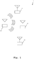
- FIG. 1 we demonstrate the general function of an according communications systems along FIG. 1 .
- FIG. 2 and 3 further details of the function of the inventive communications system are described.
- FIG. 4 an embodiment of the inventive method are shown and described in detail. Similar entities and reference numbers in different figures have been partially omitted.
- FIG. 1 a first embodiment of the inventive communications system 1 is shown.
- the communications system 1 comprises a first transceiver 10 and a number of second transceivers 11, 12, 13.
- the first transceiver 10 sends transmissions out to either all of the second transceivers 11-13 or to individual transceivers of the second transceivers 11-13.
- FIG. 3 Regarding the structure of the transmissions, it is referred to the later elaborations regarding FIG. 3 .
- Each of the transceivers 10-13 is not only able to transmit signals, but also to receive signals. Therefore, the signals transmitted by the first transceiver 10 are ideally received by the second transceivers 11-13. Signals transmitted by any of the second transceivers 11-13 are ideally received by the first transceiver 10.
- the transmission channel between the first transceiver 10 and the second transceivers 11-13 though is a real-world lossy transmission channel. Therefore, it is not guaranteed that every transmission by one of the transceivers 10-13 can be successfully received by all target transceivers.
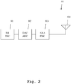
- FIG. 2 a second embodiment of the inventive communications system is shown. Especially here, some more detail of the inner construction of one of the transceivers 10-13 is shown. Although in FIG. 2 , an exemplary inner construction of transceiver 10 is shown, the construction may be similar also for the transceivers 11-13.
- the transceiver 10 comprises a baseband processor 101 connected to a digital-analog-converter / analog-digital-converter 102, which in turn is connected to an analog processor 103.
- the analog processor 103 is again connected to an antenna 104.
- a digital baseband signal is generated by the baseband processor 101 and handed on to the digital-analog-converter / analog-digital-converter 102, which converts it to an analog baseband signal.
- This analog baseband signal is then handed on to the analog processor 103, which converts it to an analog radio frequency signal, which is handed on to the antenna 104 and successively transmitted.
- the digital baseband signal 101 comprises a number of data packets. The construction of a data packet is further shown in FIG. 3 .
- the baseband processor 101 may comprise a data packet generator, which is configured to convert payload data into data packets according to a data packet structure shown in FIG. 3 .
- the baseband processor 101 may comprise a source coder configured to add redundancy to the payload data before forming packets therefrom by the packet generator.
- the baseband processor 101 may furthermore comprise a digital modulator, configured for performing a modulation to an intermediate frequency.
- the analog processor 103 may comprise a first bandpass filter configured to remove out of band signal components from the analog baseband signal provided by the digital analog converter/analog digital converter 102.
- the analog processor 103 may furthermore comprise a mixer, configured to mix the analog baseband signal or the filtered analog baseband signal with a local oscillator signal in order to achieve a transmission frequency of the analog radio frequency signal. Furthermore, the analog processor 103 may additionally comprise a second bandpass filter for removing out of band components of the signal mixed by the mixer.
- an analog radio frequency signal is received by the antenna 104 and handed on to the analog processor 103.
- the analog processor 103 converts it to an analog baseband signal and hands it on to the digital-analog-converter / analog-digital-converter 102, which converts it to a digital baseband signal.
- the digital baseband signal was handed on to the baseband processor 101, which receives the digital baseband signal and performs further processing thereupon.
- a received analog radio frequency signal may comprise data packets, which can then be extracted from the digital baseband signal. Regarding the construction of these data packets, it is again referred to the elaborations regarding FIG. 3 .
- the before-mentioned components of the baseband processor 101 and the analog processor 103 may be used.
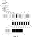
- FIG. 3 the data structure of a data packet 20 used by the communications system 1 is shown.
- the data packet 20 is comprised of a number of data packet fragments 21.
- the data packet 20 comprises 4 data packet fragments 21 1 , 21 2 , 21 3 and 21 4' .
- the data packet fragments 21 1 -21 4 are drawn apart below the initial display of the data packet fragments 21.
- each data packet fragment 21 comprises an indicator of the number of data packet fragments 21 1 -21 4 within the transmission window. This is indicated by the middle number within each of the data packet fragments 21 1 -21 4 .
- each data packet fragment 21 1 -21 4 comprises a successive number of the data packet fragment 21 1 -21 4 within the data packet. This corresponds to the upper number in any of the data packet fragments 21 1 -21 4 , as displayed in FIG. 3 .
- each data packet fragment 21 1 -21 4 comprises a sequential data packet fragment number within the transmission window. This corresponds to the lower number as depicted in FIG. 3 .
- management slots R used for reservation are shown.
- a management slot 22 is transmitted directly after the transmission of the last data packet fragment 21 4 .
- the management slot 21 is further shown in detail below.
- the data packet fragments 21 1 -21 4 together with the management slot 22 form a transmission window.
- the management slot 22 comprises a number of guard intervals 24 which separate NACK signal sub-timeslots 25 1 -25 10 . Each of these NACK signal sub-timeslots 25 directly correspond to a data packet fragment number.
- Each NACK signal sub-timeslot 25 corresponds to one of the sequential data packet fragment numbers within the transmission window. This means that the second transceiver 11 - 13 reports a NACK signal for each data packet fragment 21 it did not successfully receive, within the correct NACK signal sub-timeslot of the respective data packet fragment. For example, here the data packet fragment 21 3 has not been successfully received. This is indicated by the different color scheme. This results in the second transceiver reporting back in NACK signal sub-timeslot 25 3 that this data packet fragment 21 3 has not been successfully received by transmitting a NACK signal in this NACK signal sub-timeslot 25 3 .
- the NACK signal sub-timeslot consists of a jitter timespace 26 of a length t j it and a NACK timespace 27.
- the NACK signal is transmitted within the NACK timespace 27.
- the length of the jitter timespace 26 t j it is selected randomly by the second transceiver wishing to transmit the NACK signal.
- the length t j it is chosen so that enough time remains for transmitting the NACK signal within the NACK timespace.
- the first transceiver 10 By receiving the management slot 22, the first transceiver 10 knows which data packet fragments 21 have not been correctly received by at least one second transceiver 11 - 13, and therefore knows, which data packets 20 and data packet fragments 21 need to be retransmitted. This is also displayed in FIG. 3 . Since the first transceiver 10 learns from the management slot 22 that the data packet fragment 21 3 has not been correctly received by at least one second transceiver 11 - 13, it retransmits the data packet fragment 21 3 as data packet fragment 23 after the management slot 22. The number of the data packet fragment within the timeslot - 2 - remains the same, while the number of data packet fragments transmitted within the transmission window is now 1 and the total number of data packet fragments within the transmission window is also 1.
- the first transceiver 10 performs a dynamic slot allocation before beginning the transmission of the data packet.
- This dynamic slot allocation divides the packets into a sensible number of data packet fragments and prepares them for transmission.
- FIG. 4 a first embodiment of the inventive method is shown in a flow diagram.
- a data packet comprising at least one data packet fragment is transmitted by a first transceiver to at least one second transceiver.
- the at least one second transceiver attempts to receive all data packet fragments of the data packet.
- a not-acknowledge, NACK, signal is transmitted, if at least one data packet fragment of the data packet has not been successfully received, to the first transceiver, by the second transceiver.
- the NACK signal therein comprises a NACK sub-signal for each not successfully received data packet fragment of the data packet, each within a specific NACK signal sub-timeslot dedicated to a specific sequential data packet fragment number of the not successfully received data packet fragment of the data packet.
- FIG. 1 - FIG. 3 are also to be understood as disclosed with regard to the inventive method while on the other hand the elaborations regarding FIG. 4 are also to be understood as disclosed in regard to the inventive communications system.
- the invention is not limited to the provided examples and especially not to a specific communication standard, especially not to a specific number of packet fragments.
- the invention may be applied to many different communication standards.
- the characteristics of the exemplary embodiments can be used in any advantageous combination.
Landscapes
- Engineering & Computer Science (AREA)
- Computer Networks & Wireless Communication (AREA)
- Signal Processing (AREA)
- Mobile Radio Communication Systems (AREA)
Abstract
Description
- The invention relates to Not-Acknowledge (NACK) signaling in radio communications systems, especially Time Division Multiple Access (TDMA) systems.
- In a radio communications network, packets are to be delivered in a most robust manner to one or more participants. In a multiple access network protocol using TDMA, the data packet is subdivided into a number of data packet fragments. Each fragment is transmitted successively and then reconstituted to the entire packet by the receiver.
- If just a single one of these data packet fragments is lost during transmission, the entire packet is lost and needs to be transmitted again. In lossy communications channels, the secure transmission of large data packets is therefore difficult. For example,
EP 1 635 516 B1 - Accordingly, the object of the invention is to provide a communications system and method, which allow for a robust transmission of large data packets.
- The object is solved by the features of
claim 1 for the device and claim 10 for the method. Further it is solved by the features ofclaim 11 for the associated computer program. The dependent claims contain further developments. - An inventive direct radio transmission communications system comprises a first transceiver and at least one second transceiver. The first transceiver is configured to transmit a data packet comprising at least one data packet fragment. The at least one second transceiver is adapted to attempt to receive all the data packet fragments of the data packet. The at least one second transceiver is configured to, if at least one data packet fragment of the data packet has not been received successfully by the at least one second transceiver, transmit a Not-Acknowledge, NACK, signal to the first transceiver. The NACK signal therein comprises a NACK sub-signal for each not successfully received data packet fragment of the data packet, each within a specific NACK signal sub-timeslot dedicated to a specific sequential data packet fragment number of the not successfully received data packet fragment of the data packet. This allows for a very efficient transmission.
- Advantageously, the at least one second transceiver is configured to check which data packet fragments of the data packet have not been successfully received, before transmitting the NACK signal. This makes sure that only correct data packet fragments are indicated as not-received.
- Preferably the first transceiver is moreover configured to retransmit data packet fragments of the data packet, indicated as not received correctly. It is thereby assured that not the entire packet needs to be retransmitted, but only the actually lost fragments thereof.
- Advantageously and preferably, the at least one data packet fragment of the data packet comprises a total number of data packet fragments within the data packet within a transmission window, and/or a fragment index, indicating an order of the data packet fragment within the data packet, and/or the sequential data packet fragment number, within the transmission window. This assures an efficient NACK signaling and an efficient reconstitution of the received packets.
- Further advantageously and preferably, the first transceiver is configured to transmit the data packet fragments of the data packet in a transmission window. The transmission window comprises a number of timeslots equal to the number of data packet fragments of the data packet to transmit in addition to a management timeslot. The at least one second transceiver is adapted to transmit the NACK signal to the first transceiver during the management timeslot. This assures an efficient spectral usage.
- Further advantageously and preferably, the management timeslot comprises at least one guard interval sub-timeslot followed by at least one NACK signal sub-timeslot. This assures a time-separation of successive signals.
- Advantageously and preferably, the management timeslot comprises the dedicated NACK signal sub-timeslot for each of the sequential data packet fragment numbers. The dedicated NACK signal sub-timeslots are arranged successively within the management timeslot, separated by preceding guard intervals. By having a dedicated time-position for receiving the NACK signals of the individual fragments, a non-overlapping reception and an unambiguous signaling is assured.
- Advantageously and preferably, each NACK signal sub-timeslot is comprised of a jitter timespace and a NACK timespace. The at least one second transceiver is configured to randomly select a length of the jitter timespace, and to begin transmission of the NACK sub-signal after waiting during the jitter timespace within the NACK timespace. Especially in a multicast environment in which more than one second transceiver is the target of the transmission, resulting NACK signals from a plurality of second transceivers are thereby randomly time-shifted, assuring that two NACK signals cannot cancel each other out due to a phase shift.
- Advantageously and preferably, the first transceiver is configured to perform a dynamic slot allocation before beginning of the transmission of the data packet. This further increases transmission efficiency.
- Advantageously and preferably, after the dynamic slot allocation, the transmission has at least one transmission window followed by a management timeslot.
- An inventive direct radio transmission communication method comprises transmitting a data packet comprising at least one data packet fragment by a first transceiver, attempting to receive all of the data packet fragments by a second transceiver, if at least one data packet fragment of the data packet has not been successfully received by the at least one second transceiver, transmitting a NACK signal to the first transceiver. The NACK signal therein comprises a NACK sub-signal for each not successfully received data packet fragment of the data packet, each within a specific NACK signal sub-timeslot dedicated to a specific sequential data packet fragment number of the not successfully received data packet fragment of the data packet. This allows for a very efficient transmission.
- An inventive computer program comprises program code for performing the previously described method, when the computer program runs on a computer or a digital signal processor.
- Exemplary embodiments of the invention are now further explained with regard to the drawings in which
- FIG. 1
- shows a first embodiment of the communications system;
- FIG. 2
- shows a detail of a second embodiment of the communications system;
- FIG. 3
- shows details of a transmission in a third embodiment of the communications system, and
- FIG. 4
- shows a first embodiment of the inventive method.
- First, we demonstrate the general function of an according communications systems along
FIG. 1 . With regard toFIG. 2 and3 , further details of the function of the inventive communications system are described. Finally, alongFIG. 4 , an embodiment of the inventive method are shown and described in detail. Similar entities and reference numbers in different figures have been partially omitted. - In
FIG. 1 , a first embodiment of theinventive communications system 1 is shown. Thecommunications system 1 comprises afirst transceiver 10 and a number ofsecond transceivers first transceiver 10 sends transmissions out to either all of the second transceivers 11-13 or to individual transceivers of the second transceivers 11-13. Regarding the structure of the transmissions, it is referred to the later elaborations regardingFIG. 3 . - Each of the transceivers 10-13 is not only able to transmit signals, but also to receive signals. Therefore, the signals transmitted by the
first transceiver 10 are ideally received by the second transceivers 11-13. Signals transmitted by any of the second transceivers 11-13 are ideally received by thefirst transceiver 10. - The transmission channel between the
first transceiver 10 and the second transceivers 11-13 though is a real-world lossy transmission channel. Therefore, it is not guaranteed that every transmission by one of the transceivers 10-13 can be successfully received by all target transceivers. - In
FIG. 2 , a second embodiment of the inventive communications system is shown. Especially here, some more detail of the inner construction of one of the transceivers 10-13 is shown. Although inFIG. 2 , an exemplary inner construction oftransceiver 10 is shown, the construction may be similar also for the transceivers 11-13. - In
FIG. 2 , thetransceiver 10 comprises abaseband processor 101 connected to a digital-analog-converter / analog-digital-converter 102, which in turn is connected to ananalog processor 103. Theanalog processor 103 is again connected to anantenna 104. - When transmitting a signal, a digital baseband signal is generated by the
baseband processor 101 and handed on to the digital-analog-converter / analog-digital-converter 102, which converts it to an analog baseband signal. This analog baseband signal is then handed on to theanalog processor 103, which converts it to an analog radio frequency signal, which is handed on to theantenna 104 and successively transmitted. The digital baseband signal 101 comprises a number of data packets. The construction of a data packet is further shown inFIG. 3 . - For example, the
baseband processor 101 may comprise a data packet generator, which is configured to convert payload data into data packets according to a data packet structure shown inFIG. 3 . - Moreover, the
baseband processor 101 may comprise a source coder configured to add redundancy to the payload data before forming packets therefrom by the packet generator. - The
baseband processor 101 may furthermore comprise a digital modulator, configured for performing a modulation to an intermediate frequency. - Moreover, the
analog processor 103 may comprise a first bandpass filter configured to remove out of band signal components from the analog baseband signal provided by the digital analog converter/analogdigital converter 102. - The
analog processor 103 may furthermore comprise a mixer, configured to mix the analog baseband signal or the filtered analog baseband signal with a local oscillator signal in order to achieve a transmission frequency of the analog radio frequency signal. Furthermore, theanalog processor 103 may additionally comprise a second bandpass filter for removing out of band components of the signal mixed by the mixer. - When receiving a signal, an analog radio frequency signal is received by the
antenna 104 and handed on to theanalog processor 103. Theanalog processor 103 converts it to an analog baseband signal and hands it on to the digital-analog-converter / analog-digital-converter 102, which converts it to a digital baseband signal. The digital baseband signal was handed on to thebaseband processor 101, which receives the digital baseband signal and performs further processing thereupon. - Also, a received analog radio frequency signal may comprise data packets, which can then be extracted from the digital baseband signal. Regarding the construction of these data packets, it is again referred to the elaborations regarding
FIG. 3 . - Also, on the reception path, the before-mentioned components of the
baseband processor 101 and theanalog processor 103 may be used. - In
FIG. 3 , the data structure of adata packet 20 used by thecommunications system 1 is shown. Thedata packet 20 is comprised of a number of data packet fragments 21. In this example, thedata packet 20 comprises 4 data packet fragments 211, 212, 213 and 214'. In order to better visualize the construction of the transmission, the data packet fragments 211-214 are drawn apart below the initial display of the data packet fragments 21. - Preferably, each
data packet fragment 21 comprises an indicator of the number of data packet fragments 211-214 within the transmission window. This is indicated by the middle number within each of the data packet fragments 211-214. Moreover, preferably, each data packet fragment 211-214 comprises a successive number of the data packet fragment 211-214 within the data packet. This corresponds to the upper number in any of the data packet fragments 211-214, as displayed inFIG. 3 . Finally, advantageously, each data packet fragment 211-214 comprises a sequential data packet fragment number within the transmission window. This corresponds to the lower number as depicted inFIG. 3 . - In addition to the data packet fragments 21, here a number of management slots R used for reservation are shown.
- These are not relevant to the present invention though. Moreover, directly after the transmission of the last
data packet fragment 214, amanagement slot 22 is transmitted. Themanagement slot 21 is further shown in detail below. The data packet fragments 211-214 together with themanagement slot 22 form a transmission window. Themanagement slot 22 comprises a number ofguard intervals 24 which separate NACK signal sub-timeslots 251-2510. Each of theseNACK signal sub-timeslots 25 directly correspond to a data packet fragment number. - Each
NACK signal sub-timeslot 25 corresponds to one of the sequential data packet fragment numbers within the transmission window. This means that the second transceiver 11 - 13 reports a NACK signal for eachdata packet fragment 21 it did not successfully receive, within the correct NACK signal sub-timeslot of the respective data packet fragment. For example, here thedata packet fragment 213 has not been successfully received. This is indicated by the different color scheme. This results in the second transceiver reporting back inNACK signal sub-timeslot 253 that thisdata packet fragment 213 has not been successfully received by transmitting a NACK signal in thisNACK signal sub-timeslot 253. - In the lower part of
FIG. 3 , finally the construction of aNACK signal sub-timeslot 25, especially of theNACK signal sub-timeslot 253 is shown in detail. The NACK signal sub-timeslot consists of ajitter timespace 26 of a length tjit and aNACK timespace 27. The NACK signal is transmitted within theNACK timespace 27. The length of the jitter timespace 26 tjit is selected randomly by the second transceiver wishing to transmit the NACK signal. The length tjit is chosen so that enough time remains for transmitting the NACK signal within the NACK timespace. The jitter timespace can also have a length of tjit = 0. In a multicast environment, in which a plurality of second transceivers 11 - 14 receive the transmission, having each second transceiver having not successfully received the data packet fragment, randomly chose the length of the jitter time frame tjit assures that the NACK signals do not destructively overlap due to transmission phase shift. - By receiving the
management slot 22, thefirst transceiver 10 knows which data packet fragments 21 have not been correctly received by at least one second transceiver 11 - 13, and therefore knows, whichdata packets 20 and data packet fragments 21 need to be retransmitted. This is also displayed inFIG. 3 . Since thefirst transceiver 10 learns from themanagement slot 22 that thedata packet fragment 213 has not been correctly received by at least one second transceiver 11 - 13, it retransmits thedata packet fragment 213 as data packet fragment 23 after themanagement slot 22. The number of the data packet fragment within the timeslot - 2 - remains the same, while the number of data packet fragments transmitted within the transmission window is now 1 and the total number of data packet fragments within the transmission window is also 1. - Advantageously, the
first transceiver 10 performs a dynamic slot allocation before beginning the transmission of the data packet. This dynamic slot allocation divides the packets into a sensible number of data packet fragments and prepares them for transmission. - In
FIG. 4 , a first embodiment of the inventive method is shown in a flow diagram. - In a
first step 100, a data packet comprising at least one data packet fragment is transmitted by a first transceiver to at least one second transceiver. - In a
second step 101, the at least one second transceiver attempts to receive all data packet fragments of the data packet. - In a
third step 102, a not-acknowledge, NACK, signal, is transmitted, if at least one data packet fragment of the data packet has not been successfully received, to the first transceiver, by the second transceiver. The NACK signal therein comprises a NACK sub-signal for each not successfully received data packet fragment of the data packet, each within a specific NACK signal sub-timeslot dedicated to a specific sequential data packet fragment number of the not successfully received data packet fragment of the data packet. - It should be noted that the elaborations regarding
FIG. 1 -FIG. 3 are also to be understood as disclosed with regard to the inventive method while on the other hand the elaborations regardingFIG. 4 are also to be understood as disclosed in regard to the inventive communications system. - The invention is not limited to the provided examples and especially not to a specific communication standard, especially not to a specific number of packet fragments. The invention may be applied to many different communication standards. The characteristics of the exemplary embodiments can be used in any advantageous combination.
Claims (11)
- A direct radio transmission communication system (1), comprising a first transceiver (10) and at least one second transceiver (11, 12, 13),
wherein the first transceiver (10) is configured to transmit a data packet (20) comprising at least one data packet fragment (211, 212, 213, 214, 215),
wherein the at least one second transceiver (11, 12, 13) is configured to attempt to receive all the data packet fragments (211, 212, 213, 214, 21s) of the data packet (20),
wherein the at least one second transceiver (11, 12, 13) is configured to transmit a not-acknowledge, NACK, signal, if at least one data packet fragment (211, 212, 213, 214, 215) of the data packet (20) has not been successfully received, to the first transceiver (10), and
wherein the NACK signal comprises a NACK sub-signal for each not successfully received data packet fragment (211, 212, 213, 214, 215) of the data packet (20), each within a specific NACK signal sub-timeslot (251, 252, 253, 254, 255, 256, 257, 258, 259, 2510) dedicated to a specific sequential data packet fragment number of the not successfully received data packet fragment (211, 212, 213, 214, 21s) of the data packet (20). - The direct radio transmission communication system (1) according to claim 1,
wherein the at least one second transceiver (11, 12, 13) is configured to check which data packet fragments (211, 212, 213, 214, 215) of the data packet (20) have not been successfully received, before transmitting the NACK signal. - The direct radio transmission communication system (1) according to claim 1 or 2,
wherein the first transceiver (10) is configured to retransmit data packet fragments (211, 212, 213, 214, 21s) of the data packet (20) indicated as not received correctly. - The direct radio transmission communication system (1) according to any of the claims 1 to 3,
wherein the at least one data packet fragment (211, 212, 213, 214, 215) of the data packet (20) comprises:- a total number of data packet fragments (211, 212, 213, 214, 215) within the data packet (20), within a transmission window, and/or- a fragment index, indicating an order of the data packet fragment (211, 212, 213, 214, 215) within the data packet (20), and/or- the sequential data packet fragment number, within a transmission window. - The direct radio transmission communication system (1,) according to any of claims 1 to 4,
wherein the first transceiver (10) is configured to transmit the data packet fragments (211, 212, 213, 214, 215) of the data packet (20) in a transmission window, wherein the transmission window comprises a number of timeslots equal to the number of data packet fragments (211, 212, 213, 214, 215) of the data packet (20) to transmit in addition to a management timeslot (22), and wherein the at least one second transceiver (11, 12, 13) is adapted to transmit the NACK signal to the first transceiver (10) during the management timeslot (22). - The direct radio transmission communication system (1) according to claim 5,
wherein the management timeslot (22) comprises at least one guard interval sub-timeslot (24) followed by at least one NACK signal sub-timeslot (251, 252, 253, 254, 255, 256, 257, 258, 259, 2510). - The direct radio transmission communication system (1) according to claim 5 or 6,
wherein the management timeslot (22) comprises the dedicated NACK signal sub-timeslots (251, 252, 253, 254, 255, 256, 257, 258, 259, 2510) for each of the sequential data packet fragment numbers (211, 212, 213, 214, 215), and wherein the dedicated NACK signal sub-timeslots (251, 252, 253, 254, 255, 256, 257, 255, 259, 2510) are arranged successively within the management timeslot (22), separated by preceding guard intervals (24), - The direct radio transmission communication system (1) according to claim 7,
wherein each NACK signal sub-timeslot (251, 252, 253, 254, 255, 256, 257, 258, 259, 2510) is comprised of a jitter timespace (26) and a NACK timespace (27),
wherein the at least one second transceiver (11, 12, 13) is configured to- randomly select a length (tjit) of the jitter timespace (26), and- begin transmission of the NACK sub-signal after waiting during the jitter timespace (26), within the NACK timespace (27). - The direct radio transmission communication system (1), according to any of the claims 1 to 8,
wherein the first transceiver (10) is configured to perform a dynamic slot allocation before the beginning the transmission of the data packet (20). - A direct radio transmission communication method, comprising:- transmitting a data packet (20) comprising at least one data packet fragment (211, 212, 213, 214, 215), by a first transceiver (10),- attempting to receive all the data packet fragments (211, 212, 213, 214, 215) of the data packet (20), by a second transceiver (11, 12, 13),- transmitting a not-acknowledge, NACK, signal, if at least one data packet fragment (211, 212, 213, 214, 21s) of the data packet (20) has not been successfully received, to the first transceiver (10), by the second transceiver (111, 12, 13),wherein the NACK signal comprises a NACK sub-signal for each not successfully received data packet fragment (211, 212, 213, 214, 215) of the data packet (20), each within a specific NACK signal sub-timeslot (251, 252, 253, 254, 255, 256, 257, 258, 259, 2510) dedicated to a specific sequential data packet fragment number of the not successfully received data packet fragment (211, 212, 213, 214, 21s) of the data packet (20).
- A computer program with a program code for performing all steps of the method according to claim 10 when the computer program runs on a computer or a digital signal processor.
Priority Applications (1)
| Application Number | Priority Date | Filing Date | Title |
|---|---|---|---|
| EP19175854.9A EP3742642B8 (en) | 2019-05-22 | 2019-05-22 | Nack signaling in tdma communications |
Applications Claiming Priority (1)
| Application Number | Priority Date | Filing Date | Title |
|---|---|---|---|
| EP19175854.9A EP3742642B8 (en) | 2019-05-22 | 2019-05-22 | Nack signaling in tdma communications |
Publications (3)
| Publication Number | Publication Date |
|---|---|
| EP3742642A1 true EP3742642A1 (en) | 2020-11-25 |
| EP3742642B1 EP3742642B1 (en) | 2021-08-25 |
| EP3742642B8 EP3742642B8 (en) | 2021-09-29 |
Family
ID=66630197
Family Applications (1)
| Application Number | Title | Priority Date | Filing Date |
|---|---|---|---|
| EP19175854.9A Active EP3742642B8 (en) | 2019-05-22 | 2019-05-22 | Nack signaling in tdma communications |
Country Status (1)
| Country | Link |
|---|---|
| EP (1) | EP3742642B8 (en) |
Citations (4)
| Publication number | Priority date | Publication date | Assignee | Title |
|---|---|---|---|---|
| EP1635516A1 (en) | 2003-06-18 | 2006-03-15 | Nippon Telegraph and Telephone Corporation | Radio packet communication method |
| EP2184950A1 (en) * | 2008-11-07 | 2010-05-12 | Siemens Aktiengesellschaft | A method for data transmission in a local area network |
| US8565197B2 (en) * | 2010-08-24 | 2013-10-22 | Blackberry Limited | System and method for uplink data transfer in dynamic timeslot reduction |
| EP2757724A1 (en) * | 2011-09-16 | 2014-07-23 | Huawei Technologies Co., Ltd | Method for receiving and transmitting fragments and device for receiving and transmitting fragments |
-
2019
- 2019-05-22 EP EP19175854.9A patent/EP3742642B8/en active Active
Patent Citations (4)
| Publication number | Priority date | Publication date | Assignee | Title |
|---|---|---|---|---|
| EP1635516A1 (en) | 2003-06-18 | 2006-03-15 | Nippon Telegraph and Telephone Corporation | Radio packet communication method |
| EP2184950A1 (en) * | 2008-11-07 | 2010-05-12 | Siemens Aktiengesellschaft | A method for data transmission in a local area network |
| US8565197B2 (en) * | 2010-08-24 | 2013-10-22 | Blackberry Limited | System and method for uplink data transfer in dynamic timeslot reduction |
| EP2757724A1 (en) * | 2011-09-16 | 2014-07-23 | Huawei Technologies Co., Ltd | Method for receiving and transmitting fragments and device for receiving and transmitting fragments |
Also Published As
| Publication number | Publication date |
|---|---|
| EP3742642B1 (en) | 2021-08-25 |
| EP3742642B8 (en) | 2021-09-29 |
Similar Documents
| Publication | Publication Date | Title |
|---|---|---|
| US12041664B2 (en) | System and method for random access backoffs | |
| US5134615A (en) | Frequency agile tdma communications system | |
| US6463040B1 (en) | Methods of communicating overtime division multiple access (TDMA) communication systems with distinct non-time critical and time critical network management information transmission rates | |
| CN107231218B (en) | ACK/NACK feedback method and related equipment | |
| EP3171561B1 (en) | Signal processing method, base station and terminal | |
| US6301232B1 (en) | Methods of dynamically switching return channel transmissions of time-division multiple-access (TDMA) communication systems between signalling burst transmissions and message transmissions | |
| US5640415A (en) | Bit error performance of a frequency hopping, radio communication system | |
| EP3292646B1 (en) | Systems and methods for a subframe structure for wideband lte | |
| RU2509431C1 (en) | Relay transmission method and apparatus | |
| EP0270216A2 (en) | Dynamic frame length communication system, and stations for such a system | |
| US20180206267A1 (en) | System and Method for Co-Existence of Low-Latency and Latency-Tolerant Communication Resources | |
| US9420491B2 (en) | Method of dynamic allocation of shared resources in a time-frequency plan and associated device | |
| US8861485B2 (en) | Self-organizing communications network and method for the operation thereof | |
| US20250056590A1 (en) | Communication devices and methods | |
| CN111147213B (en) | Signal sending method and terminal | |
| US6859450B1 (en) | Method for coordinated collision avoidance in multi-transceiver frequency hopping wireless device | |
| US20120106432A1 (en) | Method for transmitting uplink signal with periodic and relay system for the same | |
| CN101409929B (en) | A communication method and device | |
| CN113852439B (en) | Burst transmitting time synchronization method of satellite countermeasure device and satellite countermeasure device | |
| US6608821B1 (en) | Method for collision avoidance in an asynchronous communication system | |
| CN109639339B (en) | Bandwidth allocation method suitable for managing large satellite FDMA communication mode | |
| EP3742642B1 (en) | Nack signaling in tdma communications | |
| US20040032878A1 (en) | Waveform for virtually simultaneous transmission and multiple receptions system and method | |
| EP3818667B1 (en) | Low latency wireless protocol for audio and gaming | |
| US11381359B2 (en) | Transmission time frame structure for time division duplex communication |
Legal Events
| Date | Code | Title | Description |
|---|---|---|---|
| PUAI | Public reference made under article 153(3) epc to a published international application that has entered the european phase |
Free format text: ORIGINAL CODE: 0009012 |
|
| STAA | Information on the status of an ep patent application or granted ep patent |
Free format text: STATUS: THE APPLICATION HAS BEEN PUBLISHED |
|
| AK | Designated contracting states |
Kind code of ref document: A1 Designated state(s): AL AT BE BG CH CY CZ DE DK EE ES FI FR GB GR HR HU IE IS IT LI LT LU LV MC MK MT NL NO PL PT RO RS SE SI SK SM TR |
|
| AX | Request for extension of the european patent |
Extension state: BA ME |
|
| STAA | Information on the status of an ep patent application or granted ep patent |
Free format text: STATUS: REQUEST FOR EXAMINATION WAS MADE |
|
| 17P | Request for examination filed |
Effective date: 20201120 |
|
| RBV | Designated contracting states (corrected) |
Designated state(s): AL AT BE BG CH CY CZ DE DK EE ES FI FR GB GR HR HU IE IS IT LI LT LU LV MC MK MT NL NO PL PT RO RS SE SI SK SM TR |
|
| RIC1 | Information provided on ipc code assigned before grant |
Ipc: H04L 1/00 20060101ALI20210430BHEP Ipc: H04L 1/18 20060101ALI20210430BHEP Ipc: H04L 1/16 20060101AFI20210430BHEP |
|
| GRAP | Despatch of communication of intention to grant a patent |
Free format text: ORIGINAL CODE: EPIDOSNIGR1 |
|
| STAA | Information on the status of an ep patent application or granted ep patent |
Free format text: STATUS: GRANT OF PATENT IS INTENDED |
|
| GRAS | Grant fee paid |
Free format text: ORIGINAL CODE: EPIDOSNIGR3 |
|
| INTG | Intention to grant announced |
Effective date: 20210611 |
|
| GRAA | (expected) grant |
Free format text: ORIGINAL CODE: 0009210 |
|
| STAA | Information on the status of an ep patent application or granted ep patent |
Free format text: STATUS: THE PATENT HAS BEEN GRANTED |
|
| AK | Designated contracting states |
Kind code of ref document: B1 Designated state(s): AL AT BE BG CH CY CZ DE DK EE ES FI FR GB GR HR HU IE IS IT LI LT LU LV MC MK MT NL NO PL PT RO RS SE SI SK SM TR |
|
| RBV | Designated contracting states (corrected) |
Designated state(s): AL AT BE BG CY CZ DE DK EE ES FI FR GB GR HR HU IS IT LT LU LV MC MK MT NL NO PL PT RO RS SE SI SK SM TR |
|
| REG | Reference to a national code |
Ref country code: IE Ref legal event code: FG4D Ref country code: AT Ref legal event code: REF Ref document number: 1424897 Country of ref document: AT Kind code of ref document: T Effective date: 20210915 |
|
| REG | Reference to a national code |
Ref country code: DE Ref legal event code: R096 Ref document number: 602019007075 Country of ref document: DE |
|
| REG | Reference to a national code |
Ref country code: LT Ref legal event code: MG9D |
|
| REG | Reference to a national code |
Ref country code: NL Ref legal event code: MP Effective date: 20210825 |
|
| REG | Reference to a national code |
Ref country code: AT Ref legal event code: MK05 Ref document number: 1424897 Country of ref document: AT Kind code of ref document: T Effective date: 20210825 |
|
| PG25 | Lapsed in a contracting state [announced via postgrant information from national office to epo] |
Ref country code: SE Free format text: LAPSE BECAUSE OF FAILURE TO SUBMIT A TRANSLATION OF THE DESCRIPTION OR TO PAY THE FEE WITHIN THE PRESCRIBED TIME-LIMIT Effective date: 20210825 Ref country code: RS Free format text: LAPSE BECAUSE OF FAILURE TO SUBMIT A TRANSLATION OF THE DESCRIPTION OR TO PAY THE FEE WITHIN THE PRESCRIBED TIME-LIMIT Effective date: 20210825 Ref country code: FI Free format text: LAPSE BECAUSE OF FAILURE TO SUBMIT A TRANSLATION OF THE DESCRIPTION OR TO PAY THE FEE WITHIN THE PRESCRIBED TIME-LIMIT Effective date: 20210825 Ref country code: ES Free format text: LAPSE BECAUSE OF FAILURE TO SUBMIT A TRANSLATION OF THE DESCRIPTION OR TO PAY THE FEE WITHIN THE PRESCRIBED TIME-LIMIT Effective date: 20210825 Ref country code: HR Free format text: LAPSE BECAUSE OF FAILURE TO SUBMIT A TRANSLATION OF THE DESCRIPTION OR TO PAY THE FEE WITHIN THE PRESCRIBED TIME-LIMIT Effective date: 20210825 Ref country code: PT Free format text: LAPSE BECAUSE OF FAILURE TO SUBMIT A TRANSLATION OF THE DESCRIPTION OR TO PAY THE FEE WITHIN THE PRESCRIBED TIME-LIMIT Effective date: 20211227 Ref country code: NO Free format text: LAPSE BECAUSE OF FAILURE TO SUBMIT A TRANSLATION OF THE DESCRIPTION OR TO PAY THE FEE WITHIN THE PRESCRIBED TIME-LIMIT Effective date: 20211125 Ref country code: BG Free format text: LAPSE BECAUSE OF FAILURE TO SUBMIT A TRANSLATION OF THE DESCRIPTION OR TO PAY THE FEE WITHIN THE PRESCRIBED TIME-LIMIT Effective date: 20211125 Ref country code: AT Free format text: LAPSE BECAUSE OF FAILURE TO SUBMIT A TRANSLATION OF THE DESCRIPTION OR TO PAY THE FEE WITHIN THE PRESCRIBED TIME-LIMIT Effective date: 20210825 Ref country code: LT Free format text: LAPSE BECAUSE OF FAILURE TO SUBMIT A TRANSLATION OF THE DESCRIPTION OR TO PAY THE FEE WITHIN THE PRESCRIBED TIME-LIMIT Effective date: 20210825 |
|
| PG25 | Lapsed in a contracting state [announced via postgrant information from national office to epo] |
Ref country code: PL Free format text: LAPSE BECAUSE OF FAILURE TO SUBMIT A TRANSLATION OF THE DESCRIPTION OR TO PAY THE FEE WITHIN THE PRESCRIBED TIME-LIMIT Effective date: 20210825 Ref country code: LV Free format text: LAPSE BECAUSE OF FAILURE TO SUBMIT A TRANSLATION OF THE DESCRIPTION OR TO PAY THE FEE WITHIN THE PRESCRIBED TIME-LIMIT Effective date: 20210825 Ref country code: GR Free format text: LAPSE BECAUSE OF FAILURE TO SUBMIT A TRANSLATION OF THE DESCRIPTION OR TO PAY THE FEE WITHIN THE PRESCRIBED TIME-LIMIT Effective date: 20211126 |
|
| PG25 | Lapsed in a contracting state [announced via postgrant information from national office to epo] |
Ref country code: NL Free format text: LAPSE BECAUSE OF FAILURE TO SUBMIT A TRANSLATION OF THE DESCRIPTION OR TO PAY THE FEE WITHIN THE PRESCRIBED TIME-LIMIT Effective date: 20210825 |
|
| PG25 | Lapsed in a contracting state [announced via postgrant information from national office to epo] |
Ref country code: DK Free format text: LAPSE BECAUSE OF FAILURE TO SUBMIT A TRANSLATION OF THE DESCRIPTION OR TO PAY THE FEE WITHIN THE PRESCRIBED TIME-LIMIT Effective date: 20210825 |
|
| REG | Reference to a national code |
Ref country code: DE Ref legal event code: R097 Ref document number: 602019007075 Country of ref document: DE |
|
| PG25 | Lapsed in a contracting state [announced via postgrant information from national office to epo] |
Ref country code: SM Free format text: LAPSE BECAUSE OF FAILURE TO SUBMIT A TRANSLATION OF THE DESCRIPTION OR TO PAY THE FEE WITHIN THE PRESCRIBED TIME-LIMIT Effective date: 20210825 Ref country code: SK Free format text: LAPSE BECAUSE OF FAILURE TO SUBMIT A TRANSLATION OF THE DESCRIPTION OR TO PAY THE FEE WITHIN THE PRESCRIBED TIME-LIMIT Effective date: 20210825 Ref country code: RO Free format text: LAPSE BECAUSE OF FAILURE TO SUBMIT A TRANSLATION OF THE DESCRIPTION OR TO PAY THE FEE WITHIN THE PRESCRIBED TIME-LIMIT Effective date: 20210825 Ref country code: EE Free format text: LAPSE BECAUSE OF FAILURE TO SUBMIT A TRANSLATION OF THE DESCRIPTION OR TO PAY THE FEE WITHIN THE PRESCRIBED TIME-LIMIT Effective date: 20210825 Ref country code: CZ Free format text: LAPSE BECAUSE OF FAILURE TO SUBMIT A TRANSLATION OF THE DESCRIPTION OR TO PAY THE FEE WITHIN THE PRESCRIBED TIME-LIMIT Effective date: 20210825 Ref country code: AL Free format text: LAPSE BECAUSE OF FAILURE TO SUBMIT A TRANSLATION OF THE DESCRIPTION OR TO PAY THE FEE WITHIN THE PRESCRIBED TIME-LIMIT Effective date: 20210825 |
|
| PLBE | No opposition filed within time limit |
Free format text: ORIGINAL CODE: 0009261 |
|
| STAA | Information on the status of an ep patent application or granted ep patent |
Free format text: STATUS: NO OPPOSITION FILED WITHIN TIME LIMIT |
|
| PG25 | Lapsed in a contracting state [announced via postgrant information from national office to epo] |
Ref country code: IT Free format text: LAPSE BECAUSE OF FAILURE TO SUBMIT A TRANSLATION OF THE DESCRIPTION OR TO PAY THE FEE WITHIN THE PRESCRIBED TIME-LIMIT Effective date: 20210825 |
|
| 26N | No opposition filed |
Effective date: 20220527 |
|
| REG | Reference to a national code |
Ref country code: BE Ref legal event code: MM Effective date: 20220531 |
|
| PG25 | Lapsed in a contracting state [announced via postgrant information from national office to epo] |
Ref country code: MC Free format text: LAPSE BECAUSE OF FAILURE TO SUBMIT A TRANSLATION OF THE DESCRIPTION OR TO PAY THE FEE WITHIN THE PRESCRIBED TIME-LIMIT Effective date: 20210825 Ref country code: LU Free format text: LAPSE BECAUSE OF NON-PAYMENT OF DUE FEES Effective date: 20220522 |
|
| PG25 | Lapsed in a contracting state [announced via postgrant information from national office to epo] |
Ref country code: BE Free format text: LAPSE BECAUSE OF NON-PAYMENT OF DUE FEES Effective date: 20220531 |
|
| P01 | Opt-out of the competence of the unified patent court (upc) registered |
Effective date: 20230525 |
|
| PG25 | Lapsed in a contracting state [announced via postgrant information from national office to epo] |
Ref country code: MK Free format text: LAPSE BECAUSE OF FAILURE TO SUBMIT A TRANSLATION OF THE DESCRIPTION OR TO PAY THE FEE WITHIN THE PRESCRIBED TIME-LIMIT Effective date: 20210825 Ref country code: CY Free format text: LAPSE BECAUSE OF FAILURE TO SUBMIT A TRANSLATION OF THE DESCRIPTION OR TO PAY THE FEE WITHIN THE PRESCRIBED TIME-LIMIT Effective date: 20210825 |
|
| PG25 | Lapsed in a contracting state [announced via postgrant information from national office to epo] |
Ref country code: HU Free format text: LAPSE BECAUSE OF FAILURE TO SUBMIT A TRANSLATION OF THE DESCRIPTION OR TO PAY THE FEE WITHIN THE PRESCRIBED TIME-LIMIT; INVALID AB INITIO Effective date: 20190522 |
|
| PG25 | Lapsed in a contracting state [announced via postgrant information from national office to epo] |
Ref country code: MT Free format text: LAPSE BECAUSE OF FAILURE TO SUBMIT A TRANSLATION OF THE DESCRIPTION OR TO PAY THE FEE WITHIN THE PRESCRIBED TIME-LIMIT Effective date: 20210825 |
|
| PG25 | Lapsed in a contracting state [announced via postgrant information from national office to epo] |
Ref country code: TR Free format text: LAPSE BECAUSE OF FAILURE TO SUBMIT A TRANSLATION OF THE DESCRIPTION OR TO PAY THE FEE WITHIN THE PRESCRIBED TIME-LIMIT Effective date: 20210825 |
|
| PG25 | Lapsed in a contracting state [announced via postgrant information from national office to epo] |
Ref country code: SI Free format text: LAPSE BECAUSE OF FAILURE TO SUBMIT A TRANSLATION OF THE DESCRIPTION OR TO PAY THE FEE WITHIN THE PRESCRIBED TIME-LIMIT Effective date: 20210825 |
|
| PGFP | Annual fee paid to national office [announced via postgrant information from national office to epo] |
Ref country code: GB Payment date: 20260324 Year of fee payment: 8 |
|
| PGFP | Annual fee paid to national office [announced via postgrant information from national office to epo] |
Ref country code: DE Payment date: 20260520 Year of fee payment: 8 |
|
| PGFP | Annual fee paid to national office [announced via postgrant information from national office to epo] |
Ref country code: FR Payment date: 20260522 Year of fee payment: 8 |