EP3742559A1 - Circular plug connector - Google Patents
Circular plug connector Download PDFInfo
- Publication number
- EP3742559A1 EP3742559A1 EP20174988.4A EP20174988A EP3742559A1 EP 3742559 A1 EP3742559 A1 EP 3742559A1 EP 20174988 A EP20174988 A EP 20174988A EP 3742559 A1 EP3742559 A1 EP 3742559A1
- Authority
- EP
- European Patent Office
- Prior art keywords
- self
- retaining
- coupling ring
- outer coupling
- supporting compression
- Prior art date
- Legal status (The legal status is an assumption and is not a legal conclusion. Google has not performed a legal analysis and makes no representation as to the accuracy of the status listed.)
- Granted
Links
Images

Classifications
-
- H—ELECTRICITY
- H01—ELECTRIC ELEMENTS
- H01R—ELECTRICALLY-CONDUCTIVE CONNECTIONS; STRUCTURAL ASSOCIATIONS OF A PLURALITY OF MUTUALLY-INSULATED ELECTRICAL CONNECTING ELEMENTS; COUPLING DEVICES; CURRENT COLLECTORS
- H01R24/00—Two-part coupling devices, or either of their cooperating parts, characterised by their overall structure
- H01R24/86—Parallel contacts arranged about a common axis
-
- H—ELECTRICITY
- H01—ELECTRIC ELEMENTS
- H01R—ELECTRICALLY-CONDUCTIVE CONNECTIONS; STRUCTURAL ASSOCIATIONS OF A PLURALITY OF MUTUALLY-INSULATED ELECTRICAL CONNECTING ELEMENTS; COUPLING DEVICES; CURRENT COLLECTORS
- H01R13/00—Details of coupling devices of the kinds covered by groups H01R12/70 or H01R24/00 - H01R33/00
- H01R13/46—Bases; Cases
- H01R13/533—Bases, cases made for use in extreme conditions, e.g. high temperature, radiation, vibration, corrosive environment, pressure
-
- H—ELECTRICITY
- H01—ELECTRIC ELEMENTS
- H01R—ELECTRICALLY-CONDUCTIVE CONNECTIONS; STRUCTURAL ASSOCIATIONS OF A PLURALITY OF MUTUALLY-INSULATED ELECTRICAL CONNECTING ELEMENTS; COUPLING DEVICES; CURRENT COLLECTORS
- H01R13/00—Details of coupling devices of the kinds covered by groups H01R12/70 or H01R24/00 - H01R33/00
- H01R13/46—Bases; Cases
- H01R13/502—Bases; Cases composed of different pieces
-
- H—ELECTRICITY
- H01—ELECTRIC ELEMENTS
- H01R—ELECTRICALLY-CONDUCTIVE CONNECTIONS; STRUCTURAL ASSOCIATIONS OF A PLURALITY OF MUTUALLY-INSULATED ELECTRICAL CONNECTING ELEMENTS; COUPLING DEVICES; CURRENT COLLECTORS
- H01R13/00—Details of coupling devices of the kinds covered by groups H01R12/70 or H01R24/00 - H01R33/00
- H01R13/62—Means for facilitating engagement or disengagement of coupling parts or for holding them in engagement
- H01R13/622—Screw-ring or screw-casing
-
- H—ELECTRICITY
- H01—ELECTRIC ELEMENTS
- H01R—ELECTRICALLY-CONDUCTIVE CONNECTIONS; STRUCTURAL ASSOCIATIONS OF A PLURALITY OF MUTUALLY-INSULATED ELECTRICAL CONNECTING ELEMENTS; COUPLING DEVICES; CURRENT COLLECTORS
- H01R13/00—Details of coupling devices of the kinds covered by groups H01R12/70 or H01R24/00 - H01R33/00
- H01R13/648—Protective earth or shield arrangements on coupling devices, e.g. anti-static shielding
- H01R13/658—High frequency shielding arrangements, e.g. against EMI [Electro-Magnetic Interference] or EMP [Electro-Magnetic Pulse]
- H01R13/6581—Shield structure
-
- H—ELECTRICITY
- H01—ELECTRIC ELEMENTS
- H01R—ELECTRICALLY-CONDUCTIVE CONNECTIONS; STRUCTURAL ASSOCIATIONS OF A PLURALITY OF MUTUALLY-INSULATED ELECTRICAL CONNECTING ELEMENTS; COUPLING DEVICES; CURRENT COLLECTORS
- H01R13/00—Details of coupling devices of the kinds covered by groups H01R12/70 or H01R24/00 - H01R33/00
- H01R13/648—Protective earth or shield arrangements on coupling devices, e.g. anti-static shielding
- H01R13/658—High frequency shielding arrangements, e.g. against EMI [Electro-Magnetic Interference] or EMP [Electro-Magnetic Pulse]
- H01R13/6581—Shield structure
- H01R13/6582—Shield structure with resilient means for engaging mating connector
-
- H—ELECTRICITY
- H01—ELECTRIC ELEMENTS
- H01R—ELECTRICALLY-CONDUCTIVE CONNECTIONS; STRUCTURAL ASSOCIATIONS OF A PLURALITY OF MUTUALLY-INSULATED ELECTRICAL CONNECTING ELEMENTS; COUPLING DEVICES; CURRENT COLLECTORS
- H01R2107/00—Four or more poles
Definitions
- the subject matter herein relates generally to electrical connectors.
- Some known electrical connectors provide an interface for high speed data transmission cables.
- the cables typically include shielded parallel pair cables or various types of coaxial cables terminated to contacts arranged within the electrical connector.
- Some known electrical connectors are manufactured according to military specifications. For example, in electronic enclosures, panel connectors are used to interconnect signals originating inside enclosures and/or avionic boxes. MIL-C-38999 connectors are popular connectors used widely in the military and aerospace avionics applications. However, the electrical connectors are used in harsh environments and subject to vibration.
- Some known electrical connectors utilize a spring element contained within the connector housing to maintain mating compliance.
- the electrical connectors use multiple retaining components to hold the spring element in place within the electrical connector, such as a retaining washer and a snap ring to hold the retaining washer and the spring element in the connector housing.
- the multiple components add additional parts and assembly complexity for the electrical connector, leading to additional cost for the manufacture and assembly of the electrical connector.
- the solution is provided by a circular plug connector.
- the circular plug connector includes an outer coupling ring that has a cavity extending between a front and a rear.
- the outer coupling ring includes a retaining element proximate to the rear.
- the outer coupling ring includes a mating element proximate to the front that is configured to be coupled to a mating connector.
- a plug shell extends between a front and a rear.
- the plug shell houses one or more plug contacts that are configured to be coupled to the mating connector.
- the plug shell has a front body at the front configured to be coupled to the mating connector.
- the plug shell has a rear body at the rear.
- the plug shell includes a mid-body between the front body and the rear body that has a rear facing support surface.
- the circular plug connector includes a self-supporting compression element surrounding the rear body.
- the self-supporting compression element extends between a front and a rear.
- the self-supporting compression element includes a spring element at the front.
- the self-supporting compression element includes a retaining shim support at the rear.
- the retaining shim support is integral with the spring element as a unitary, monolithic body.
- the retaining shim support is received in the retaining element to fix the self-supporting compression element relative to the outer coupling ring.
- the spring element engages the rear facing support surface to support the plug shell within the cavity of the outer coupling ring.
- the spring element is compressible relative to the retaining shim support to allow the plug shell to move axially within the cavity of the outer coupling ring.
- a circular plug connector in one embodiment, includes an outer coupling ring that has a cavity extending between a front and a rear.
- the outer coupling ring includes a retaining element proximate to the rear.
- the outer coupling ring includes a mating element proximate to the front that is configured to be coupled to a mating connector.
- a plug shell extends between a front and a rear.
- the plug shell houses one or more plug contacts that are configured to be coupled to the mating connector.
- the plug shell has a front body at the front configured to be coupled to the mating connector.
- the plug shell has a rear body at the rear.
- the plug shell includes a mid-body between the front body and the rear body that has a rear facing support surface.
- the circular plug connector includes a self-supporting compression element surrounding the rear body.
- the self-supporting compression element extends between a front and a rear.
- the self-supporting compression element includes a spring element at the front.
- the self-supporting compression element includes a retaining shim support at the rear.
- the retaining shim support is integral with the spring element as a unitary, monolithic body.
- the retaining shim support is received in the retaining element to fix the self-supporting compression element relative to the outer coupling ring.
- the spring element engages the rear facing support surface to support the plug shell within the cavity of the outer coupling ring.
- the spring element is compressible relative to the retaining shim support to allow the plug shell to move axially within the cavity of the outer coupling ring.
- a circular plug connector in another embodiment, includes an outer coupling ring that has a cavity extending between a front and a rear.
- the outer coupling ring includes a retaining element proximate to the rear.
- the outer coupling ring includes a mating element proximate to the front that is configured to be coupled to a mating connector.
- a plug shell extends between a front and a rear.
- the plug shell houses one or more plug contacts that are configured to be coupled to the mating connector.
- the plug shell has a front body at the front configured to be coupled to the mating connector.
- the plug shell has a rear body at the rear.
- the plug shell includes a mid-body between the front body and the rear body having a rear facing support surface.
- the circular plug connector includes a self-supporting compression element surrounding the rear body.
- the self-supporting compression element is received in the retaining element to fix the self-supporting compression element relative to the outer coupling ring.
- the self-supporting compression element engages the rear facing support surface to support the plug shell within the cavity of the outer coupling ring.
- the self-supporting compression element is compressible to allow the plug shell to move axially within the cavity of the outer coupling ring.
- a connector system in a further embodiment, includes a circular plug connector and a circular mating connector coupled together.
- the circular mating connector includes an outer housing that has a mating end and an inner housing that is received in the outer housing.
- the inner housing holds mating contacts.
- the circular plug connector includes an outer coupling ring that has a cavity extending between a front and a rear.
- the outer coupling ring includes a retaining element proximate to the rear.
- the outer coupling ring includes a mating element proximate to the front coupled to the mating end of the circular mating connector.
- the circular plug connector includes a plug shell extending between a front and a rear. The plug shell houses plug contacts coupled to corresponding mating contacts of the mating connector.
- the plug shell has a front body at the front coupled to the outer housing of the mating connector.
- the plug shell has a rear body at the rear.
- the plug shell includes a mid-body between the front body and the rear body having a rear facing support surface.
- the circular plug connector includes a self-supporting compression element surrounding the rear body.
- the self-supporting compression element extends between a front and a rear.
- the self-supporting compression element includes a spring element at the front.
- the self-supporting compression element includes a retaining shim support at the rear.
- the retaining shim support is integral with the spring element as a unitary, monolithic body.
- the retaining shim support is received in the retaining element to fix the self-supporting compression element relative to the outer coupling ring.
- the spring element engages the rear facing support surface to support the plug shell within the cavity of the outer coupling ring.
- the spring element is compressible relative to the retaining shim support to allow the plug shell to
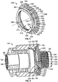
- FIG. 1 illustrates a connector system 100 formed in accordance with an exemplary embodiment.
- the connector system 100 includes a circular plug connector 102 and a circular mating connector 104 configured to be mated together.
- the connector system 100 is used to connect two data communication cables (not shown) together or to connect a data communication cable to a circuit board (not shown).
- the data communication cable(s) may be Ethernet cables transmitting data across a computer network.
- the data communication cable(s) may be fiber optic cables.
- the circular plug connector 102 is configured to be terminated to the end of the corresponding data communication cable or mounted to a circuit board.
- the circular mating connector 104 is configured to be terminated to the end of the corresponding data communication cable or mounted to a circuit board.
- the circular plug connector 102 and circular mating connector 104 are mated together to create an electrical connection therebetween. Data is transmitted across the interface between the circular plug connector 102 and the circular mating connector 104.
- the circular plug connector 102 and circular mating connector 104 are designed for use in a rugged environment, such as an environment that is subject to extreme shock, vibration and the like.
- the connector system 100 is configured for use in military applications that require data capability in harsh environments. Other applications include industrial applications, aerospace applications, marine applications, and the like. The subject matter herein may have application in other moderate environments, such as in building network systems.
- the circular plug connector 102 and the circular mating connector 104 constitute high performance cylindrical connectors, designed in accordance with the MIL-DTL-38999 standard.
- the circular mating connector 104 may be panel mounted.
- the circular mating connector 104 includes an outer housing 110 having a cavity 112 therein.
- the outer housing 110 includes a mounting flange 113 for mounting the circular mating connector 104 to a panel or other structure.
- An inner housing 114 is received in the cavity 112.
- the inner housing 114 includes mating contacts 116 configured to be mated with the plug contacts 126.
- an outer surface of the outer housing 110 may include threads 118 for threaded mating with the circular plug connector 102.
- the circular plug connector 102 includes a plug shell 120 having a cavity 122 therein.
- a plug insert 124 is received in the plug shell 120.
- the plug shell 120 and the plug insert 124 are generally cylindrical.
- the plug insert 124 includes plug contacts 126.
- the plug shell 120 is manufactured from a metal material and may provide electrical shielding for the plug contacts 126 and the plug insert 124.
- the mating contacts 116 are pin contacts and the plug contacts 126 are socket contacts configured to receive the pin contacts to create an electrical connection therebetween.
- the mating contacts 116 are socket contacts and the plug contacts 126 are pin contacts. Other types of contacts may be used in alternative embodiments, such as fiber-optic contacts.
- the circular plug connector 102 includes an outer coupling ring 130 surrounding the plug shell 120.
- the outer coupling ring 130 includes a mating element 132 used to secure the circular plug connector 102 to the circular mating connector 104.
- the outer coupler ring 130 is generally cylindrical.
- the outer coupler ring 130 may be manufactured from metal material or plastic material.
- the outer coupling ring 130 may be a threaded coupler.
- the mating element 132 of the outer coupler ring 130 may include internal threads for threadably coupling the circular plug connector 102 to the circular mating connector 104.
- the mating element 132 may be another type of mating element, such as a bayonet coupler, a breech lock coupler or another type of coupler.
- the plug contacts 126 are mated with the mating contacts 116 to make a data communication connection therebetween. Data is transmitted across the interface between the connectors 102, 104.
- a robust connection is provided between the circular plug connector 102 and the circular mating connector 104.
- the robust connection is capable of withstanding harsh environments, such as vibration and shock.
- the circular plug connector 102 may include a compression element between the outer coupling ring 130 and the plug shell 120 that allows relative movement therebetween to withstand the stresses due to vibration and shock.
- Figure 2 is a cross-sectional view of the circular plug connector 102 in accordance with an exemplary embodiment.
- Figure 2 illustrates the plug insert 124 received in the cavity 122 of the plug shell 120.
- Figure 2 illustrates the plug contacts 126 held in contact channels 140 of the plug insert 124. Cables 142 are terminated to ends of the plug contacts 126 and extend rearward from the plug insert 124.
- Figure 2 shows the outer coupling ring 130 coupled to the plug shell 120.
- the plug shell 120 extends between a front 144 and a rear 146.
- the plug shell 120 includes a front body 150 at the front 144, a rear body 152 at the rear 146 and a mid-body 154 between the front body 150 and the rear body 152.
- the plug shell 120 is a unitary structure with the front body 150, the rear body 152, and the mid body 154 being integral with each other as part of a monolithic structure.
- the plug shell 120 is generally cylindrical along an axial length of the plug shell 120.
- the plug shell 120 is machined to form the various features along the exterior of the plug shell 120 and to form the cavity 122.
- the plug shell 120 is die-cast.
- the cavity 122 is open at the front 144 to expose the plug contacts 126 for mating with the mating contacts 116 (shown in Figure 1 ).
- the cavity 122 is open at the rear 146 to allow the cables 142 to exit the plug shell 120.
- the rear body 152 includes threads 156, such as for attachment of a cable ferrule or other connector to the rear body 152 of the plug shell 120.
- the rear body 152 may include serrations 158 at the rear 146, such as for attachment to a cable jacket, a cable ferrule or other component.
- the mid body 154 includes a flange 160 extending therefrom.
- the flange 160 includes a front facing the support surface 162 and a rear facing support surface 164.
- the flange 160 has a larger diameter than the rear body 152 rearward of the flange 160 and the front body 150 forward of the flange 160.
- the front body 150 includes one or more keying features 166 extending along the exterior surface of the plug shell 120 configured to interact with the circular mating connector 104 for keyed mating with the circular mating connector 104.
- the outer coupling ring 130 extends between a front 170 and a rear 172.
- the outer coupling ring 130 includes a cavity 174 that receives the plug shell 120.
- the mating element 132 is provided on the interior surface of the outer coupling ring 130 defining the cavity 174.
- the mating element 132 is located proximate to the front 170.
- a space 176 is defined in the cavity 174 between the inner surface of the outer coupling ring 130 and the outer surface of the plug shell 120. The space 176 receives the outer housing 110 (shown in Figure 1 ) of the circular mating connector 104.
- the outer coupling ring 130 includes a locating shoulder 178 within the cavity 174.
- the locating shoulder 178 is used for locating the plug shell 120 within the cavity 174.
- the locating shoulder 178 is rearward facing.
- the front facing support surface 162 of the flange 160 is configured to be positioned against the locating shoulder 178 to axially position the plug shell 120 within the cavity 174.
- a self-supporting compression element 200 is used to forward bias the plug shell 120 against the locating shoulder 178.
- the self-supporting compression element 200 is located rearward of the flange 160 and engages the rear facing support surface 164 to push the plug shell 120 in a forward direction against the locating shoulder 178.
- the self-supporting compression element 200 is self-supporting within the outer coupling ring 130 without the need for separate or discrete retention components to retain the self-supporting compression element 200 in the outer coupling ring 130.
- the outer coupling ring 130 includes a retaining element 180 formed in the inner surface of the outer coupling ring 130.
- the retaining element 180 may be a groove in various embodiments.
- the retaining element 180 may be a shoulder, a tab or other type of retaining element in other various embodiments.
- the retaining element 180 extends entirely circumferentially around the outer coupling ring 130.
- the self-supporting compression element 200 is received in and retained by the retaining element 180.
- the retaining element 180 includes a rear lip 182 that defines a bearing surface for the self-supporting compression element 200.
- the self-supporting compression element 200 bears against the rear lip 182 and springs forward there from against the rear facing support surface 164 of the flange 160.
- the outer coupling ring 130 is rotatable relative to the self-supporting compression element 200 and the plug shell 120, such as for threadably coupling to the circular mating connector 104.
- the self-supporting compression element 200 is compressible between the flange 160 and the rear lip 182.
- the self-supporting compression element 200 may be compressed as the outer coupling ring 130 is threaded or tightened onto the circular mating connector 104 and/or the plug shell 120 may be pressed rearward, such as during mating and/or vibration, to force the flange 160 rearward from the locating shoulder 168, which compresses the self-supporting compression element 200.
- FIG. 3 is a front perspective view of the self-supporting compression element 200 in accordance with an exemplary embodiment.
- the self-supporting compression element 200 is a single piece structure having a continuous coil body 202 extending continuously between a first end 204 and a second end 206.
- the coil body 202 may be extruded or cut from a single piece of metal material.
- the coil body 202 may be produced by a winding process or edge winding process.
- the self-supporting compression element 200 extends axially along a central axis 208 between a front 210 and a rear 212.
- the self-supporting compression element 200 is compressible along the central axis 208.
- the self-supporting compression element 200 includes an opening 214 along the central axis 208.
- the self-supporting compression element 200 is circular.
- the self-supporting compression element 200 is spiral shaped.
- the continuous coil body 202 includes a plurality of loops wrapped around the central axis 208.
- the self-supporting compression element 200 includes a spring element 220 at the front 210 and a retaining shim support 222 at the rear 212.
- the spring element 220 is integral with the retaining shim support 222 to form the unitary, monolithic coil body 202.
- the spring element 220 is compressible against the retaining shim support 222.
- the retaining shim support 222 forms a backing layer for the spring element 220.
- the spring element 220 includes a plurality of spring loops 230 being compressible to form the spring element 220.
- the spring element 220 is a wave spring having the spring loops 230 arranged in wave patterns.
- each spring loop 230 has undulating segments (for example, peaks and valleys).
- Adjacent spring loops 230 have converging sections 232 and diverging sections 234. The converging sections 232 converge toward each other and engage each other at support points 236. The diverging sections 232 diverge away from each other.
- Forward spring loops 230 are supported by rearward spring loops 230.
- Other types of spring elements 220 may be provided in alternative embodiments, such as a coil spring, a leaf spring, and the like.
- the spring loops 230 may be compressed rearward toward the retaining shim support 222.
- the rearward-most spring loop 230 is directly supported by (for example, bears against) the retaining shim support 222.
- the spring element 220 includes a rear mating interface 242 that interfaces with the retaining shim support 222.
- the rear mating interface 242 may be defined by discrete, spaced apart support points where the wave shaped rear spring loop engages the retaining shim support 222.
- the spring element 220 includes a front mating interface 240 at the front 210 configured to engage the plug shell 120 (shown in Figure 2 ).
- the front mating interface 240 may be defined by discrete, spaced apart support points where the wave shaped front spring loop engages the plug shell 120.
- the retaining shim support 222 is spiral shaped and includes a plurality of spiral loops 250 rearward of the spring element 220.
- the spiral loops 250 support each other from the rear 212 toward the front 210.
- each spiral loop 250 includes a forward-facing bearing surface 252 that supports the spiral loop 250 forward of the corresponding spiral loop 250.
- Each spiral loop 250 includes an overlapping segment 254 that engages the forward-facing bearing surface 252 of the spiral loop 250 behind the corresponding spiral loop 250.
- the retaining shim support 222 is a conical helix having spiral loops 250 of different diameters, such as successively larger diameters from front to rear.
- the retaining shim support 222 includes an inner loop 260 and an outer loop 262.
- the bearing surface 252 of the inner loop 260 supports the spring element 220.
- the outer loop 262 has a larger diameter than the inner loop 260.
- One or more intermediary loops 264 may be provided between the inner loop 260 and the outer loop 262.
- the outer loop 262 is configured to engage the retaining element 180 of the outer coupling ring 130 (both shown in Figure 2 ) to position the self-supporting compression element 200 relative to the outer coupling ring 130.
- the retaining shim support 222 of the self-supporting compression element 200 is radially compressible during assembly in an inward direction (for example, to reduce the diameter of the retaining shim support 222) to fit in the outer coupling ring 130 during assembly.
- the retaining shim support 222 is radially expanded (for example, to increase and expand the diameter of the retaining shim support 222) to engage the retaining element 180 and hold the self-supporting compression element 200 in the outer coupling ring 130.
- Figure 4 is a front perspective, partial sectional view of the circular plug connector 102 in accordance with an exemplary embodiment.
- Figure 4 illustrates the plug insert 124 received in the cavity 122 of the plug shell 120.
- Figure 4 illustrates the self-supporting compression element 200 coupled to the outer coupling ring 130 and the plug shell 120.
- the rear body 152 of the plug shell 120 is received in the opening 214 of the self-supporting compression element 200.
- the spring element 220 engages the flange 160.
- the front mating interface 240 of the front spring loop 230 engages the rear facing support surface 164 of the flange 160.
- the spring element 220 forward biases the plug shell 120 relative to the outer coupling ring 130.
- the retaining shim support 222 is received in the retaining element 180 to fix the position of the retaining shim support 222 relative to the outer coupling ring 130.
- the outer loop 262, having the largest diameter, is received in the retaining element 180 and abuts against the rear lip 182.
- the intermediate loops 264 and the inner loop 260 are supported by the outer loop 262.
- the overlapping segments 254 of the spiral loops 250 engage the bearing surfaces 252 of the immediately rearward spiral loop 250 to rigidly position the spiral loops 250 relative to the outer coupling ring 130.
- the retaining shim support 222 has a non-compressible thickness along the central axis 208.
- each of the spiral loops 250 abut against each other to form the retaining shim support 222 used to shim and support the spring element 220.
- the retaining shim support 222 provides a bearing surface for the spring element 220.
- the spring element 220 extends forward of the retaining shim support 222 and has a compressible thickness along the central axis 208.
- the spring loops 230 may be compressed during mating with the circular mating connector 104 and/or during shock or vibration when the circular plug connector 102 is in use.
Landscapes
- Details Of Connecting Devices For Male And Female Coupling (AREA)
Abstract
Description
- The subject matter herein relates generally to electrical connectors.
- Some known electrical connectors provide an interface for high speed data transmission cables. The cables typically include shielded parallel pair cables or various types of coaxial cables terminated to contacts arranged within the electrical connector. Some known electrical connectors are manufactured according to military specifications. For example, in electronic enclosures, panel connectors are used to interconnect signals originating inside enclosures and/or avionic boxes. MIL-C-38999 connectors are popular connectors used widely in the military and aerospace avionics applications. However, the electrical connectors are used in harsh environments and subject to vibration. Some known electrical connectors utilize a spring element contained within the connector housing to maintain mating compliance. However, the electrical connectors use multiple retaining components to hold the spring element in place within the electrical connector, such as a retaining washer and a snap ring to hold the retaining washer and the spring element in the connector housing. The multiple components add additional parts and assembly complexity for the electrical connector, leading to additional cost for the manufacture and assembly of the electrical connector.
- The solution is provided by a circular plug connector. The circular plug connector includes an outer coupling ring that has a cavity extending between a front and a rear. The outer coupling ring includes a retaining element proximate to the rear. The outer coupling ring includes a mating element proximate to the front that is configured to be coupled to a mating connector. A plug shell extends between a front and a rear. The plug shell houses one or more plug contacts that are configured to be coupled to the mating connector. The plug shell has a front body at the front configured to be coupled to the mating connector. The plug shell has a rear body at the rear. The plug shell includes a mid-body between the front body and the rear body that has a rear facing support surface. The circular plug connector includes a self-supporting compression element surrounding the rear body. The self-supporting compression element extends between a front and a rear. The self-supporting compression element includes a spring element at the front. The self-supporting compression element includes a retaining shim support at the rear. The retaining shim support is integral with the spring element as a unitary, monolithic body. The retaining shim support is received in the retaining element to fix the self-supporting compression element relative to the outer coupling ring. The spring element engages the rear facing support surface to support the plug shell within the cavity of the outer coupling ring. The spring element is compressible relative to the retaining shim support to allow the plug shell to move axially within the cavity of the outer coupling ring.
- The invention will now be described by way of example with reference to the accompanying drawings in which:
-
Figure 1 illustrates a connector system having a circular plug connector formed in accordance with an exemplary embodiment. -
Figure 2 is a cross-sectional view of the circular plug connector in accordance with an exemplary embodiment. -
Figure 3 is a front perspective view of a self-supporting compression element of the circular plug connector in accordance with an exemplary embodiment. -
Figure 4 is a front perspective, partial sectional view of the circular plug connector in accordance with an exemplary embodiment. - In one embodiment, a circular plug connector is provided. The circular plug connector includes an outer coupling ring that has a cavity extending between a front and a rear. The outer coupling ring includes a retaining element proximate to the rear. The outer coupling ring includes a mating element proximate to the front that is configured to be coupled to a mating connector. A plug shell extends between a front and a rear. The plug shell houses one or more plug contacts that are configured to be coupled to the mating connector. The plug shell has a front body at the front configured to be coupled to the mating connector. The plug shell has a rear body at the rear. The plug shell includes a mid-body between the front body and the rear body that has a rear facing support surface. The circular plug connector includes a self-supporting compression element surrounding the rear body. The self-supporting compression element extends between a front and a rear. The self-supporting compression element includes a spring element at the front. The self-supporting compression element includes a retaining shim support at the rear. The retaining shim support is integral with the spring element as a unitary, monolithic body. The retaining shim support is received in the retaining element to fix the self-supporting compression element relative to the outer coupling ring. The spring element engages the rear facing support surface to support the plug shell within the cavity of the outer coupling ring. The spring element is compressible relative to the retaining shim support to allow the plug shell to move axially within the cavity of the outer coupling ring.
- In another embodiment, a circular plug connector is provided. The circular plug connector includes an outer coupling ring that has a cavity extending between a front and a rear. The outer coupling ring includes a retaining element proximate to the rear. The outer coupling ring includes a mating element proximate to the front that is configured to be coupled to a mating connector. A plug shell extends between a front and a rear. The plug shell houses one or more plug contacts that are configured to be coupled to the mating connector. The plug shell has a front body at the front configured to be coupled to the mating connector. The plug shell has a rear body at the rear. The plug shell includes a mid-body between the front body and the rear body having a rear facing support surface. The circular plug connector includes a self-supporting compression element surrounding the rear body. The self-supporting compression element is received in the retaining element to fix the self-supporting compression element relative to the outer coupling ring. The self-supporting compression element engages the rear facing support surface to support the plug shell within the cavity of the outer coupling ring. The self-supporting compression element is compressible to allow the plug shell to move axially within the cavity of the outer coupling ring.
- In a further embodiment, a connector system is provided. The connector system includes a circular plug connector and a circular mating connector coupled together. The circular mating connector includes an outer housing that has a mating end and an inner housing that is received in the outer housing. The inner housing holds mating contacts. The circular plug connector includes an outer coupling ring that has a cavity extending between a front and a rear. The outer coupling ring includes a retaining element proximate to the rear. The outer coupling ring includes a mating element proximate to the front coupled to the mating end of the circular mating connector. The circular plug connector includes a plug shell extending between a front and a rear. The plug shell houses plug contacts coupled to corresponding mating contacts of the mating connector. The plug shell has a front body at the front coupled to the outer housing of the mating connector. The plug shell has a rear body at the rear. The plug shell includes a mid-body between the front body and the rear body having a rear facing support surface. The circular plug connector includes a self-supporting compression element surrounding the rear body. The self-supporting compression element extends between a front and a rear. The self-supporting compression element includes a spring element at the front. The self-supporting compression element includes a retaining shim support at the rear. The retaining shim support is integral with the spring element as a unitary, monolithic body. The retaining shim support is received in the retaining element to fix the self-supporting compression element relative to the outer coupling ring. The spring element engages the rear facing support surface to support the plug shell within the cavity of the outer coupling ring. The spring element is compressible relative to the retaining shim support to allow the plug shell to move axially within the cavity of the outer coupling ring.
-
Figure 1 illustrates aconnector system 100 formed in accordance with an exemplary embodiment. Theconnector system 100 includes acircular plug connector 102 and acircular mating connector 104 configured to be mated together. Theconnector system 100 is used to connect two data communication cables (not shown) together or to connect a data communication cable to a circuit board (not shown). For example, the data communication cable(s) may be Ethernet cables transmitting data across a computer network. The data communication cable(s) may be fiber optic cables. Thecircular plug connector 102 is configured to be terminated to the end of the corresponding data communication cable or mounted to a circuit board. Thecircular mating connector 104 is configured to be terminated to the end of the corresponding data communication cable or mounted to a circuit board. Thecircular plug connector 102 andcircular mating connector 104 are mated together to create an electrical connection therebetween. Data is transmitted across the interface between thecircular plug connector 102 and thecircular mating connector 104. - In an exemplary embodiment, the
circular plug connector 102 andcircular mating connector 104 are designed for use in a rugged environment, such as an environment that is subject to extreme shock, vibration and the like. In one exemplary application, theconnector system 100 is configured for use in military applications that require data capability in harsh environments. Other applications include industrial applications, aerospace applications, marine applications, and the like. The subject matter herein may have application in other moderate environments, such as in building network systems. In the illustrated environment, thecircular plug connector 102 and thecircular mating connector 104 constitute high performance cylindrical connectors, designed in accordance with the MIL-DTL-38999 standard. Optionally, thecircular mating connector 104 may be panel mounted. - The
circular mating connector 104 includes anouter housing 110 having acavity 112 therein. In the illustrated embodiment, theouter housing 110 includes a mountingflange 113 for mounting thecircular mating connector 104 to a panel or other structure. Aninner housing 114 is received in thecavity 112. Theinner housing 114 includesmating contacts 116 configured to be mated with theplug contacts 126. Optionally, an outer surface of theouter housing 110 may includethreads 118 for threaded mating with thecircular plug connector 102. - The
circular plug connector 102 includes aplug shell 120 having acavity 122 therein. Aplug insert 124 is received in theplug shell 120. In an exemplary embodiment, theplug shell 120 and theplug insert 124 are generally cylindrical. Theplug insert 124 includesplug contacts 126. In an exemplary embodiment, theplug shell 120 is manufactured from a metal material and may provide electrical shielding for theplug contacts 126 and theplug insert 124. In the illustrated embodiment, themating contacts 116 are pin contacts and theplug contacts 126 are socket contacts configured to receive the pin contacts to create an electrical connection therebetween. In other various embodiments, themating contacts 116 are socket contacts and theplug contacts 126 are pin contacts. Other types of contacts may be used in alternative embodiments, such as fiber-optic contacts. - In an exemplary embodiment, the
circular plug connector 102 includes anouter coupling ring 130 surrounding theplug shell 120. Theouter coupling ring 130 includes amating element 132 used to secure thecircular plug connector 102 to thecircular mating connector 104. Theouter coupler ring 130 is generally cylindrical. Theouter coupler ring 130 may be manufactured from metal material or plastic material. In various embodiments, theouter coupling ring 130 may be a threaded coupler. For example, themating element 132 of theouter coupler ring 130 may include internal threads for threadably coupling thecircular plug connector 102 to thecircular mating connector 104. In other various embodiments, themating element 132 may be another type of mating element, such as a bayonet coupler, a breech lock coupler or another type of coupler. - When the
circular plug connector 102 is coupled to thecircular mating connector 104, theplug contacts 126 are mated with themating contacts 116 to make a data communication connection therebetween. Data is transmitted across the interface between theconnectors outer housing 110 and theplug shell 120 are coupled together, a robust connection is provided between thecircular plug connector 102 and thecircular mating connector 104. The robust connection is capable of withstanding harsh environments, such as vibration and shock. The connection between theplug shell 120 and theouter housing 110, such as via theouter coupling ring 130, withstands the forces exerted by the harsh environment, such that the interface between theconnectors circular plug connector 102 may include a compression element between theouter coupling ring 130 and theplug shell 120 that allows relative movement therebetween to withstand the stresses due to vibration and shock. -
Figure 2 is a cross-sectional view of thecircular plug connector 102 in accordance with an exemplary embodiment.Figure 2 illustrates theplug insert 124 received in thecavity 122 of theplug shell 120.Figure 2 illustrates theplug contacts 126 held incontact channels 140 of theplug insert 124.Cables 142 are terminated to ends of theplug contacts 126 and extend rearward from theplug insert 124.Figure 2 shows theouter coupling ring 130 coupled to theplug shell 120. - The
plug shell 120 extends between a front 144 and a rear 146. Theplug shell 120 includes afront body 150 at the front 144, arear body 152 at the rear 146 and a mid-body 154 between thefront body 150 and therear body 152. In an exemplary embodiment, theplug shell 120 is a unitary structure with thefront body 150, therear body 152, and themid body 154 being integral with each other as part of a monolithic structure. Theplug shell 120 is generally cylindrical along an axial length of theplug shell 120. In various embodiments, theplug shell 120 is machined to form the various features along the exterior of theplug shell 120 and to form thecavity 122. In other various embodiments, theplug shell 120 is die-cast. Thecavity 122 is open at the front 144 to expose theplug contacts 126 for mating with the mating contacts 116 (shown inFigure 1 ). Thecavity 122 is open at the rear 146 to allow thecables 142 to exit theplug shell 120. - In an exemplary embodiment, the
rear body 152 includesthreads 156, such as for attachment of a cable ferrule or other connector to therear body 152 of theplug shell 120. Optionally, therear body 152 may includeserrations 158 at the rear 146, such as for attachment to a cable jacket, a cable ferrule or other component. In an exemplary embodiment, themid body 154 includes aflange 160 extending therefrom. Theflange 160 includes a front facing thesupport surface 162 and a rear facingsupport surface 164. Theflange 160 has a larger diameter than therear body 152 rearward of theflange 160 and thefront body 150 forward of theflange 160. In an exemplary embodiment, thefront body 150 includes one or more keying features 166 extending along the exterior surface of theplug shell 120 configured to interact with thecircular mating connector 104 for keyed mating with thecircular mating connector 104. - The
outer coupling ring 130 extends between a front 170 and a rear 172. Theouter coupling ring 130 includes acavity 174 that receives theplug shell 120. Themating element 132 is provided on the interior surface of theouter coupling ring 130 defining thecavity 174. Themating element 132 is located proximate to thefront 170. Aspace 176 is defined in thecavity 174 between the inner surface of theouter coupling ring 130 and the outer surface of theplug shell 120. Thespace 176 receives the outer housing 110 (shown inFigure 1 ) of thecircular mating connector 104. - In an exemplary embodiment, the
outer coupling ring 130 includes a locatingshoulder 178 within thecavity 174. The locatingshoulder 178 is used for locating theplug shell 120 within thecavity 174. In the illustrated embodiment, the locatingshoulder 178 is rearward facing. The front facingsupport surface 162 of theflange 160 is configured to be positioned against the locatingshoulder 178 to axially position theplug shell 120 within thecavity 174. In an exemplary embodiment, a self-supportingcompression element 200 is used to forward bias theplug shell 120 against the locatingshoulder 178. The self-supportingcompression element 200 is located rearward of theflange 160 and engages the rear facingsupport surface 164 to push theplug shell 120 in a forward direction against the locatingshoulder 178. The self-supportingcompression element 200 is self-supporting within theouter coupling ring 130 without the need for separate or discrete retention components to retain the self-supportingcompression element 200 in theouter coupling ring 130. - In an exemplary embodiment, the
outer coupling ring 130 includes a retainingelement 180 formed in the inner surface of theouter coupling ring 130. The retainingelement 180 may be a groove in various embodiments. The retainingelement 180 may be a shoulder, a tab or other type of retaining element in other various embodiments. In an exemplary embodiment, the retainingelement 180 extends entirely circumferentially around theouter coupling ring 130. The self-supportingcompression element 200 is received in and retained by the retainingelement 180. The retainingelement 180 includes arear lip 182 that defines a bearing surface for the self-supportingcompression element 200. The self-supportingcompression element 200 bears against therear lip 182 and springs forward there from against the rear facingsupport surface 164 of theflange 160. In an exemplary embodiment, theouter coupling ring 130 is rotatable relative to the self-supportingcompression element 200 and theplug shell 120, such as for threadably coupling to thecircular mating connector 104. In an exemplary embodiment, the self-supportingcompression element 200 is compressible between theflange 160 and therear lip 182. For example, the self-supportingcompression element 200 may be compressed as theouter coupling ring 130 is threaded or tightened onto thecircular mating connector 104 and/or theplug shell 120 may be pressed rearward, such as during mating and/or vibration, to force theflange 160 rearward from the locating shoulder 168, which compresses the self-supportingcompression element 200. -
Figure 3 is a front perspective view of the self-supportingcompression element 200 in accordance with an exemplary embodiment. The self-supportingcompression element 200 is a single piece structure having acontinuous coil body 202 extending continuously between afirst end 204 and asecond end 206. For example, thecoil body 202 may be extruded or cut from a single piece of metal material. Thecoil body 202 may be produced by a winding process or edge winding process. The self-supportingcompression element 200 extends axially along acentral axis 208 between a front 210 and a rear 212. The self-supportingcompression element 200 is compressible along thecentral axis 208. The self-supportingcompression element 200 includes anopening 214 along thecentral axis 208. In an exemplary embodiment, the self-supportingcompression element 200 is circular. The self-supportingcompression element 200 is spiral shaped. For example, thecontinuous coil body 202 includes a plurality of loops wrapped around thecentral axis 208. - In an exemplary embodiment, the self-supporting
compression element 200 includes aspring element 220 at the front 210 and a retainingshim support 222 at the rear 212. Thespring element 220 is integral with the retainingshim support 222 to form the unitary,monolithic coil body 202. In an exemplary embodiment, thespring element 220 is compressible against the retainingshim support 222. The retainingshim support 222 forms a backing layer for thespring element 220. - The
spring element 220 includes a plurality ofspring loops 230 being compressible to form thespring element 220. In an exemplary embodiment, thespring element 220 is a wave spring having thespring loops 230 arranged in wave patterns. For example, eachspring loop 230 has undulating segments (for example, peaks and valleys).Adjacent spring loops 230 have convergingsections 232 and divergingsections 234. The convergingsections 232 converge toward each other and engage each other at support points 236. The divergingsections 232 diverge away from each other.Forward spring loops 230 are supported byrearward spring loops 230. Other types ofspring elements 220 may be provided in alternative embodiments, such as a coil spring, a leaf spring, and the like. Thespring loops 230 may be compressed rearward toward the retainingshim support 222. Therearward-most spring loop 230 is directly supported by (for example, bears against) the retainingshim support 222. For example, thespring element 220 includes arear mating interface 242 that interfaces with the retainingshim support 222. Therear mating interface 242 may be defined by discrete, spaced apart support points where the wave shaped rear spring loop engages the retainingshim support 222. Thespring element 220 includes afront mating interface 240 at the front 210 configured to engage the plug shell 120 (shown inFigure 2 ). Thefront mating interface 240 may be defined by discrete, spaced apart support points where the wave shaped front spring loop engages theplug shell 120. - The retaining
shim support 222 is spiral shaped and includes a plurality ofspiral loops 250 rearward of thespring element 220. Thespiral loops 250 support each other from the rear 212 toward the front 210. For example, eachspiral loop 250 includes a forward-facingbearing surface 252 that supports thespiral loop 250 forward of thecorresponding spiral loop 250. Eachspiral loop 250 includes an overlappingsegment 254 that engages the forward-facingbearing surface 252 of thespiral loop 250 behind thecorresponding spiral loop 250. In an exemplary embodiment, the retainingshim support 222 is a conical helix havingspiral loops 250 of different diameters, such as successively larger diameters from front to rear. The retainingshim support 222 includes aninner loop 260 and anouter loop 262. The bearingsurface 252 of theinner loop 260 supports thespring element 220. Theouter loop 262 has a larger diameter than theinner loop 260. One or moreintermediary loops 264 may be provided between theinner loop 260 and theouter loop 262. In an exemplary embodiment, theouter loop 262 is configured to engage the retainingelement 180 of the outer coupling ring 130 (both shown inFigure 2 ) to position the self-supportingcompression element 200 relative to theouter coupling ring 130. In an exemplary embodiment, the retainingshim support 222 of the self-supportingcompression element 200 is radially compressible during assembly in an inward direction (for example, to reduce the diameter of the retaining shim support 222) to fit in theouter coupling ring 130 during assembly. The retainingshim support 222 is radially expanded (for example, to increase and expand the diameter of the retaining shim support 222) to engage the retainingelement 180 and hold the self-supportingcompression element 200 in theouter coupling ring 130. -
Figure 4 is a front perspective, partial sectional view of thecircular plug connector 102 in accordance with an exemplary embodiment.Figure 4 illustrates theplug insert 124 received in thecavity 122 of theplug shell 120.Figure 4 illustrates the self-supportingcompression element 200 coupled to theouter coupling ring 130 and theplug shell 120. - When assembled, the
rear body 152 of theplug shell 120 is received in theopening 214 of the self-supportingcompression element 200. Thespring element 220 engages theflange 160. For example, thefront mating interface 240 of thefront spring loop 230 engages the rear facingsupport surface 164 of theflange 160. Thespring element 220 forward biases theplug shell 120 relative to theouter coupling ring 130. The retainingshim support 222 is received in the retainingelement 180 to fix the position of the retainingshim support 222 relative to theouter coupling ring 130. Theouter loop 262, having the largest diameter, is received in the retainingelement 180 and abuts against therear lip 182. Theintermediate loops 264 and theinner loop 260 are supported by theouter loop 262. The overlappingsegments 254 of thespiral loops 250 engage the bearing surfaces 252 of the immediately rearwardspiral loop 250 to rigidly position thespiral loops 250 relative to theouter coupling ring 130. - In an exemplary embodiment, the retaining
shim support 222 has a non-compressible thickness along thecentral axis 208. For example, each of thespiral loops 250 abut against each other to form the retainingshim support 222 used to shim and support thespring element 220. The retainingshim support 222 provides a bearing surface for thespring element 220. Thespring element 220 extends forward of the retainingshim support 222 and has a compressible thickness along thecentral axis 208. For example, thespring loops 230 may be compressed during mating with thecircular mating connector 104 and/or during shock or vibration when thecircular plug connector 102 is in use.
Claims (11)
- A circular plug connector (102) comprising:an outer coupling ring (130) having a cavity (174) extending between a front (170) and a rear (174), the outer coupling ring (130) including a retaining element (180) proximate to the rear (174), the outer coupling ring (130) including a mating element (132) proximate to the front (170) configured to be coupled to a mating connector (104);a plug shell (120) extending between a front (144) and a rear (146), the plug shell (120) housing one or more plug contacts (126) configured to be coupled to the mating connector (104), the plug shell (120) having a front body (150) at the front (144) configured to be coupled to the mating connector (104), the plug shell (120) having a rear body (152) at the rear (146), the plug shell (120) including a mid-body (154) between the front body (150) and the rear body (152) having a rear facing support surface (164); anda self-supporting compression element (200) surrounding the rear body (152), the self-supporting compression element (200) extending between a front (210) and a rear (212), the self-supporting compression element (200) including a spring element (220) at the front (210), the self-supporting compression element (200) including a retaining shim support (222) at the rear (212), the retaining shim support (222) being integral with the spring element (220) as a unitary monolithic body, the retaining shim support (222) being received in the retaining element (180) to fix the self-supporting compression element (200) relative to the outer coupling ring (130), the spring element (220) engaging the rear facing support surface (164) to support the plug shell (120) within the cavity (174) of the outer coupling ring (130), the spring element (220) being compressible relative to the retaining shim support (222) to allow the plug shell (120) to move axially within the cavity (174) of the outer coupling ring (130).
- The circular plug connector (102) of claim 1, wherein the self-supporting compression element (200) includes an outer edge (262) received in the retaining element (180).
- The circular plug connector (102) of claim 1 or 2, wherein the self-supporting compression element (200) includes a continuous coil body (202) defining the spring element (220) and the retaining shim support (222).
- The circular plug connector (102) of any preceding claim, wherein the self-supporting compression element (200) is radially compressible during assembly to fit in the outer coupling ring (130) during assembly and radially expandable to engage the retaining element (180) and hold the self-supporting compression element (200) in the outer coupling ring (130).
- The circular plug connector (102) of any preceding claim, wherein the retaining shim support (222) includes a bearing surface (252) supporting the spring element (220).
- The circular plug connector (102) of any preceding claim, wherein the retaining shim support (222) is a conical helix having an inner loop (260) and an outer loop (262), the inner loop (260) including a bearing surface (252) supporting the spring element (220), the outer loop (262) being received in the retaining element (180).
- The circular plug connector (102) of any preceding claim, wherein the retaining shim support (222) is spiral shaped and has a plurality of spiral loops (250) rearward of the spring element (220).
- The circular plug connector (102) of claim 7, wherein the spiral loops (250) have successively larger diameters, the spiral loops (250) having overlapping segments (254) defining bearing surfaces (252).
- The circular plug connector (102) of any preceding claim, wherein the spring element (220) includes a front mating interface (240) and a rear mating interface (242), the front mating interface (240) facing the rear facing support surface (164), the rear mating interface (242) facing the retaining shim support (222).
- The circular plug connector (102) of any preceding claim, wherein the spring element (220) has a compressible thickness and wherein the retaining shim support (222) has a non-compressible thickness.
- The circular plug connector (102) of any preceding claim, wherein the self-supporting compression element (220) has a variable diameter along an axial length of the self-supporting compression element (220).
Applications Claiming Priority (1)
| Application Number | Priority Date | Filing Date | Title |
|---|---|---|---|
| US16/417,759 US10637182B1 (en) | 2019-05-21 | 2019-05-21 | Circular plug connector |
Publications (2)
| Publication Number | Publication Date |
|---|---|
| EP3742559A1 true EP3742559A1 (en) | 2020-11-25 |
| EP3742559B1 EP3742559B1 (en) | 2022-11-23 |
Family
ID=70332353
Family Applications (1)
| Application Number | Title | Priority Date | Filing Date |
|---|---|---|---|
| EP20174988.4A Active EP3742559B1 (en) | 2019-05-21 | 2020-05-15 | Circular plug connector |
Country Status (2)
| Country | Link |
|---|---|
| US (1) | US10637182B1 (en) |
| EP (1) | EP3742559B1 (en) |
Families Citing this family (1)
| Publication number | Priority date | Publication date | Assignee | Title |
|---|---|---|---|---|
| DE102023122243A1 (en) * | 2023-08-21 | 2025-02-27 | Bayerische Motoren Werke Aktiengesellschaft | Shaft spring for a shaft bearing arrangement, housing for a shaft bearing arrangement, shaft bearing arrangement, machine and motor vehicle |
Citations (5)
| Publication number | Priority date | Publication date | Assignee | Title |
|---|---|---|---|---|
| US4820185A (en) * | 1988-01-20 | 1989-04-11 | Hughes Aircraft Company | Anti-backlash automatic locking connector coupling mechanism |
| US20140227900A1 (en) * | 2014-04-17 | 2014-08-14 | Tyco Electronics Corporation | Connector having coupling mechanism |
| EP2779321A1 (en) * | 2013-03-13 | 2014-09-17 | Amphenol Corporation | Anti-decoupling member for connector component |
| EP2873888A1 (en) * | 2013-11-14 | 2015-05-20 | Cooper Technologies Company | Retaining wave spring |
| US20190074631A1 (en) * | 2017-09-06 | 2019-03-07 | Torin Lee Bowman | Electrical connector with pull release |
Family Cites Families (4)
| Publication number | Priority date | Publication date | Assignee | Title |
|---|---|---|---|---|
| US4901987A (en) | 1988-05-03 | 1990-02-20 | Smalley Steel Ring Company | Crest-to-crest compression spring with circular flat shim ends |
| US6758465B1 (en) | 2002-03-05 | 2004-07-06 | Smalley Steel Ring Company | Wave spring with single shim end |
| DE102016212923B4 (en) * | 2016-07-14 | 2025-02-06 | Te Connectivity Germany Gmbh | Vibration-damping plug with a vibration damper and assembly comprising this plug and a mating plug |
| JP6671332B2 (en) * | 2017-12-11 | 2020-03-25 | 矢崎総業株式会社 | Power distribution box tolerance absorbing structure and vehicle circuit |
-
2019
- 2019-05-21 US US16/417,759 patent/US10637182B1/en active Active
-
2020
- 2020-05-15 EP EP20174988.4A patent/EP3742559B1/en active Active
Patent Citations (5)
| Publication number | Priority date | Publication date | Assignee | Title |
|---|---|---|---|---|
| US4820185A (en) * | 1988-01-20 | 1989-04-11 | Hughes Aircraft Company | Anti-backlash automatic locking connector coupling mechanism |
| EP2779321A1 (en) * | 2013-03-13 | 2014-09-17 | Amphenol Corporation | Anti-decoupling member for connector component |
| EP2873888A1 (en) * | 2013-11-14 | 2015-05-20 | Cooper Technologies Company | Retaining wave spring |
| US20140227900A1 (en) * | 2014-04-17 | 2014-08-14 | Tyco Electronics Corporation | Connector having coupling mechanism |
| US20190074631A1 (en) * | 2017-09-06 | 2019-03-07 | Torin Lee Bowman | Electrical connector with pull release |
Also Published As
| Publication number | Publication date |
|---|---|
| US10637182B1 (en) | 2020-04-28 |
| EP3742559B1 (en) | 2022-11-23 |
Similar Documents
| Publication | Publication Date | Title |
|---|---|---|
| EP3167512B1 (en) | Electrical connector for high-speed transmission using twisted-pair cable | |
| US6464527B2 (en) | Quick connect coaxial cable connector | |
| US6468100B1 (en) | BMA interconnect adapter | |
| EP2304847B1 (en) | Snap-on coaxial cable connector | |
| CA2756189C (en) | Rf connector assembly | |
| US9431780B2 (en) | Coaxial adapter with an adapter body forward projecting member | |
| JP6304805B2 (en) | Electrical connector with differential pair | |
| US5297227A (en) | Disengagable adapter for an optical fiber connection | |
| US4846719A (en) | Plural contact pin jack adapted to receive any of a plurality of different types of plugs | |
| US10490941B2 (en) | RF connector for an RF module | |
| US8992250B1 (en) | Clockable cable adapter | |
| US20170365956A1 (en) | Enclosure Assembly For a Connector | |
| US11150412B2 (en) | Tunable fiber optic connectors | |
| KR102623340B1 (en) | Plug connectors and plug connector assemblies | |
| US7094971B2 (en) | Coaxial cable Y-splitter assembly and method | |
| US11677172B2 (en) | Easily assembled coaxial cable and connector with rear body | |
| EP3742559B1 (en) | Circular plug connector | |
| EP3561966B1 (en) | Electrical connection assembly | |
| EP0497463A2 (en) | Screening arrangement for connectors | |
| US10454195B2 (en) | Electrical connector | |
| EP0617572B1 (en) | Composite canned data bus coupler connector | |
| CN217215205U (en) | Single-core and double-core radio frequency connection assembly mounted behind plate for antenna | |
| EP4387012A1 (en) | Circular plug connector | |
| JP7846764B2 (en) | connector | |
| US4346953A (en) | Antenna coupling assembly |
Legal Events
| Date | Code | Title | Description |
|---|---|---|---|
| PUAI | Public reference made under article 153(3) epc to a published international application that has entered the european phase |
Free format text: ORIGINAL CODE: 0009012 |
|
| STAA | Information on the status of an ep patent application or granted ep patent |
Free format text: STATUS: THE APPLICATION HAS BEEN PUBLISHED |
|
| AK | Designated contracting states |
Kind code of ref document: A1 Designated state(s): AL AT BE BG CH CY CZ DE DK EE ES FI FR GB GR HR HU IE IS IT LI LT LU LV MC MK MT NL NO PL PT RO RS SE SI SK SM TR |
|
| AX | Request for extension of the european patent |
Extension state: BA ME |
|
| STAA | Information on the status of an ep patent application or granted ep patent |
Free format text: STATUS: REQUEST FOR EXAMINATION WAS MADE |
|
| 17P | Request for examination filed |
Effective date: 20210524 |
|
| RBV | Designated contracting states (corrected) |
Designated state(s): AL AT BE BG CH CY CZ DE DK EE ES FI FR GB GR HR HU IE IS IT LI LT LU LV MC MK MT NL NO PL PT RO RS SE SI SK SM TR |
|
| GRAP | Despatch of communication of intention to grant a patent |
Free format text: ORIGINAL CODE: EPIDOSNIGR1 |
|
| STAA | Information on the status of an ep patent application or granted ep patent |
Free format text: STATUS: GRANT OF PATENT IS INTENDED |
|
| RIC1 | Information provided on ipc code assigned before grant |
Ipc: H01R 13/6582 20110101ALN20220523BHEP Ipc: H01R 24/86 20110101ALI20220523BHEP Ipc: H01R 13/622 20060101ALI20220523BHEP Ipc: H01R 13/533 20060101AFI20220523BHEP |
|
| INTG | Intention to grant announced |
Effective date: 20220620 |
|
| GRAS | Grant fee paid |
Free format text: ORIGINAL CODE: EPIDOSNIGR3 |
|
| GRAA | (expected) grant |
Free format text: ORIGINAL CODE: 0009210 |
|
| STAA | Information on the status of an ep patent application or granted ep patent |
Free format text: STATUS: THE PATENT HAS BEEN GRANTED |
|
| AK | Designated contracting states |
Kind code of ref document: B1 Designated state(s): AL AT BE BG CH CY CZ DE DK EE ES FI FR GB GR HR HU IE IS IT LI LT LU LV MC MK MT NL NO PL PT RO RS SE SI SK SM TR |
|
| REG | Reference to a national code |
Ref country code: GB Ref legal event code: FG4D |
|
| REG | Reference to a national code |
Ref country code: CH Ref legal event code: EP |
|
| REG | Reference to a national code |
Ref country code: DE Ref legal event code: R096 Ref document number: 602020006403 Country of ref document: DE |
|
| REG | Reference to a national code |
Ref country code: AT Ref legal event code: REF Ref document number: 1533726 Country of ref document: AT Kind code of ref document: T Effective date: 20221215 |
|
| REG | Reference to a national code |
Ref country code: IE Ref legal event code: FG4D |
|
| REG | Reference to a national code |
Ref country code: LT Ref legal event code: MG9D |
|
| REG | Reference to a national code |
Ref country code: NL Ref legal event code: MP Effective date: 20221123 |
|
| REG | Reference to a national code |
Ref country code: AT Ref legal event code: MK05 Ref document number: 1533726 Country of ref document: AT Kind code of ref document: T Effective date: 20221123 |
|
| PG25 | Lapsed in a contracting state [announced via postgrant information from national office to epo] |
Ref country code: SE Free format text: LAPSE BECAUSE OF FAILURE TO SUBMIT A TRANSLATION OF THE DESCRIPTION OR TO PAY THE FEE WITHIN THE PRESCRIBED TIME-LIMIT Effective date: 20221123 Ref country code: PT Free format text: LAPSE BECAUSE OF FAILURE TO SUBMIT A TRANSLATION OF THE DESCRIPTION OR TO PAY THE FEE WITHIN THE PRESCRIBED TIME-LIMIT Effective date: 20230323 Ref country code: NO Free format text: LAPSE BECAUSE OF FAILURE TO SUBMIT A TRANSLATION OF THE DESCRIPTION OR TO PAY THE FEE WITHIN THE PRESCRIBED TIME-LIMIT Effective date: 20230223 Ref country code: LT Free format text: LAPSE BECAUSE OF FAILURE TO SUBMIT A TRANSLATION OF THE DESCRIPTION OR TO PAY THE FEE WITHIN THE PRESCRIBED TIME-LIMIT Effective date: 20221123 Ref country code: FI Free format text: LAPSE BECAUSE OF FAILURE TO SUBMIT A TRANSLATION OF THE DESCRIPTION OR TO PAY THE FEE WITHIN THE PRESCRIBED TIME-LIMIT Effective date: 20221123 Ref country code: ES Free format text: LAPSE BECAUSE OF FAILURE TO SUBMIT A TRANSLATION OF THE DESCRIPTION OR TO PAY THE FEE WITHIN THE PRESCRIBED TIME-LIMIT Effective date: 20221123 Ref country code: AT Free format text: LAPSE BECAUSE OF FAILURE TO SUBMIT A TRANSLATION OF THE DESCRIPTION OR TO PAY THE FEE WITHIN THE PRESCRIBED TIME-LIMIT Effective date: 20221123 |
|
| PG25 | Lapsed in a contracting state [announced via postgrant information from national office to epo] |
Ref country code: RS Free format text: LAPSE BECAUSE OF FAILURE TO SUBMIT A TRANSLATION OF THE DESCRIPTION OR TO PAY THE FEE WITHIN THE PRESCRIBED TIME-LIMIT Effective date: 20221123 Ref country code: PL Free format text: LAPSE BECAUSE OF FAILURE TO SUBMIT A TRANSLATION OF THE DESCRIPTION OR TO PAY THE FEE WITHIN THE PRESCRIBED TIME-LIMIT Effective date: 20221123 Ref country code: LV Free format text: LAPSE BECAUSE OF FAILURE TO SUBMIT A TRANSLATION OF THE DESCRIPTION OR TO PAY THE FEE WITHIN THE PRESCRIBED TIME-LIMIT Effective date: 20221123 Ref country code: IS Free format text: LAPSE BECAUSE OF FAILURE TO SUBMIT A TRANSLATION OF THE DESCRIPTION OR TO PAY THE FEE WITHIN THE PRESCRIBED TIME-LIMIT Effective date: 20230323 Ref country code: HR Free format text: LAPSE BECAUSE OF FAILURE TO SUBMIT A TRANSLATION OF THE DESCRIPTION OR TO PAY THE FEE WITHIN THE PRESCRIBED TIME-LIMIT Effective date: 20221123 Ref country code: GR Free format text: LAPSE BECAUSE OF FAILURE TO SUBMIT A TRANSLATION OF THE DESCRIPTION OR TO PAY THE FEE WITHIN THE PRESCRIBED TIME-LIMIT Effective date: 20230224 |
|
| PG25 | Lapsed in a contracting state [announced via postgrant information from national office to epo] |
Ref country code: NL Free format text: LAPSE BECAUSE OF FAILURE TO SUBMIT A TRANSLATION OF THE DESCRIPTION OR TO PAY THE FEE WITHIN THE PRESCRIBED TIME-LIMIT Effective date: 20221123 |
|
| PG25 | Lapsed in a contracting state [announced via postgrant information from national office to epo] |
Ref country code: SM Free format text: LAPSE BECAUSE OF FAILURE TO SUBMIT A TRANSLATION OF THE DESCRIPTION OR TO PAY THE FEE WITHIN THE PRESCRIBED TIME-LIMIT Effective date: 20221123 Ref country code: RO Free format text: LAPSE BECAUSE OF FAILURE TO SUBMIT A TRANSLATION OF THE DESCRIPTION OR TO PAY THE FEE WITHIN THE PRESCRIBED TIME-LIMIT Effective date: 20221123 Ref country code: EE Free format text: LAPSE BECAUSE OF FAILURE TO SUBMIT A TRANSLATION OF THE DESCRIPTION OR TO PAY THE FEE WITHIN THE PRESCRIBED TIME-LIMIT Effective date: 20221123 Ref country code: DK Free format text: LAPSE BECAUSE OF FAILURE TO SUBMIT A TRANSLATION OF THE DESCRIPTION OR TO PAY THE FEE WITHIN THE PRESCRIBED TIME-LIMIT Effective date: 20221123 Ref country code: CZ Free format text: LAPSE BECAUSE OF FAILURE TO SUBMIT A TRANSLATION OF THE DESCRIPTION OR TO PAY THE FEE WITHIN THE PRESCRIBED TIME-LIMIT Effective date: 20221123 |
|
| REG | Reference to a national code |
Ref country code: DE Ref legal event code: R097 Ref document number: 602020006403 Country of ref document: DE |
|
| PG25 | Lapsed in a contracting state [announced via postgrant information from national office to epo] |
Ref country code: SK Free format text: LAPSE BECAUSE OF FAILURE TO SUBMIT A TRANSLATION OF THE DESCRIPTION OR TO PAY THE FEE WITHIN THE PRESCRIBED TIME-LIMIT Effective date: 20221123 Ref country code: AL Free format text: LAPSE BECAUSE OF FAILURE TO SUBMIT A TRANSLATION OF THE DESCRIPTION OR TO PAY THE FEE WITHIN THE PRESCRIBED TIME-LIMIT Effective date: 20221123 |
|
| PLBE | No opposition filed within time limit |
Free format text: ORIGINAL CODE: 0009261 |
|
| STAA | Information on the status of an ep patent application or granted ep patent |
Free format text: STATUS: NO OPPOSITION FILED WITHIN TIME LIMIT |
|
| 26N | No opposition filed |
Effective date: 20230824 |
|
| PG25 | Lapsed in a contracting state [announced via postgrant information from national office to epo] |
Ref country code: SI Free format text: LAPSE BECAUSE OF FAILURE TO SUBMIT A TRANSLATION OF THE DESCRIPTION OR TO PAY THE FEE WITHIN THE PRESCRIBED TIME-LIMIT Effective date: 20221123 |
|
| REG | Reference to a national code |
Ref country code: CH Ref legal event code: PL |
|
| PG25 | Lapsed in a contracting state [announced via postgrant information from national office to epo] |
Ref country code: MC Free format text: LAPSE BECAUSE OF FAILURE TO SUBMIT A TRANSLATION OF THE DESCRIPTION OR TO PAY THE FEE WITHIN THE PRESCRIBED TIME-LIMIT Effective date: 20221123 |
|
| REG | Reference to a national code |
Ref country code: BE Ref legal event code: MM Effective date: 20230531 |
|
| PG25 | Lapsed in a contracting state [announced via postgrant information from national office to epo] |
Ref country code: MC Free format text: LAPSE BECAUSE OF FAILURE TO SUBMIT A TRANSLATION OF THE DESCRIPTION OR TO PAY THE FEE WITHIN THE PRESCRIBED TIME-LIMIT Effective date: 20221123 Ref country code: LU Free format text: LAPSE BECAUSE OF NON-PAYMENT OF DUE FEES Effective date: 20230515 Ref country code: LI Free format text: LAPSE BECAUSE OF NON-PAYMENT OF DUE FEES Effective date: 20230531 Ref country code: CH Free format text: LAPSE BECAUSE OF NON-PAYMENT OF DUE FEES Effective date: 20230531 |
|
| REG | Reference to a national code |
Ref country code: IE Ref legal event code: MM4A |
|
| PG25 | Lapsed in a contracting state [announced via postgrant information from national office to epo] |
Ref country code: IE Free format text: LAPSE BECAUSE OF NON-PAYMENT OF DUE FEES Effective date: 20230515 |
|
| PG25 | Lapsed in a contracting state [announced via postgrant information from national office to epo] |
Ref country code: IE Free format text: LAPSE BECAUSE OF NON-PAYMENT OF DUE FEES Effective date: 20230515 |
|
| PG25 | Lapsed in a contracting state [announced via postgrant information from national office to epo] |
Ref country code: IT Free format text: LAPSE BECAUSE OF FAILURE TO SUBMIT A TRANSLATION OF THE DESCRIPTION OR TO PAY THE FEE WITHIN THE PRESCRIBED TIME-LIMIT Effective date: 20221123 Ref country code: BE Free format text: LAPSE BECAUSE OF NON-PAYMENT OF DUE FEES Effective date: 20230531 |
|
| PG25 | Lapsed in a contracting state [announced via postgrant information from national office to epo] |
Ref country code: BG Free format text: LAPSE BECAUSE OF FAILURE TO SUBMIT A TRANSLATION OF THE DESCRIPTION OR TO PAY THE FEE WITHIN THE PRESCRIBED TIME-LIMIT Effective date: 20221123 |
|
| PG25 | Lapsed in a contracting state [announced via postgrant information from national office to epo] |
Ref country code: BG Free format text: LAPSE BECAUSE OF FAILURE TO SUBMIT A TRANSLATION OF THE DESCRIPTION OR TO PAY THE FEE WITHIN THE PRESCRIBED TIME-LIMIT Effective date: 20221123 |
|
| PGFP | Annual fee paid to national office [announced via postgrant information from national office to epo] |
Ref country code: DE Payment date: 20250319 Year of fee payment: 6 |
|
| PG25 | Lapsed in a contracting state [announced via postgrant information from national office to epo] |
Ref country code: CY Free format text: LAPSE BECAUSE OF FAILURE TO SUBMIT A TRANSLATION OF THE DESCRIPTION OR TO PAY THE FEE WITHIN THE PRESCRIBED TIME-LIMIT; INVALID AB INITIO Effective date: 20200515 |
|
| PG25 | Lapsed in a contracting state [announced via postgrant information from national office to epo] |
Ref country code: HU Free format text: LAPSE BECAUSE OF FAILURE TO SUBMIT A TRANSLATION OF THE DESCRIPTION OR TO PAY THE FEE WITHIN THE PRESCRIBED TIME-LIMIT; INVALID AB INITIO Effective date: 20200515 |
|
| REG | Reference to a national code |
Ref country code: GB Ref legal event code: 732E Free format text: REGISTERED BETWEEN 20250731 AND 20250806 |
|
| PG25 | Lapsed in a contracting state [announced via postgrant information from national office to epo] |
Ref country code: TR Free format text: LAPSE BECAUSE OF FAILURE TO SUBMIT A TRANSLATION OF THE DESCRIPTION OR TO PAY THE FEE WITHIN THE PRESCRIBED TIME-LIMIT Effective date: 20221123 |
|
| PGFP | Annual fee paid to national office [announced via postgrant information from national office to epo] |
Ref country code: GB Payment date: 20260313 Year of fee payment: 7 |
|
| PGFP | Annual fee paid to national office [announced via postgrant information from national office to epo] |
Ref country code: FR Payment date: 20260309 Year of fee payment: 7 |