EP3742553A1 - Vertical polarized antenna and terminal device - Google Patents
Vertical polarized antenna and terminal device Download PDFInfo
- Publication number
- EP3742553A1 EP3742553A1 EP19741478.2A EP19741478A EP3742553A1 EP 3742553 A1 EP3742553 A1 EP 3742553A1 EP 19741478 A EP19741478 A EP 19741478A EP 3742553 A1 EP3742553 A1 EP 3742553A1
- Authority
- EP
- European Patent Office
- Prior art keywords
- aperture
- antenna
- vertical polarization
- cavity structure
- polarization antenna
- Prior art date
- Legal status (The legal status is an assumption and is not a legal conclusion. Google has not performed a legal analysis and makes no representation as to the accuracy of the status listed.)
- Granted
Links
Images




Classifications
-
- H—ELECTRICITY
- H01—ELECTRIC ELEMENTS
- H01Q—ANTENNAS, i.e. RADIO AERIALS
- H01Q9/00—Electrically-short antennas having dimensions not more than twice the operating wavelength and consisting of conductive active radiating elements
- H01Q9/04—Resonant antennas
- H01Q9/16—Resonant antennas with feed intermediate between the extremities of the antenna, e.g. centre-fed dipole
- H01Q9/18—Vertical disposition of the antenna
-
- H—ELECTRICITY
- H01—ELECTRIC ELEMENTS
- H01Q—ANTENNAS, i.e. RADIO AERIALS
- H01Q13/00—Waveguide horns or mouths; Slot antennas; Leaky-waveguide antennas; Equivalent structures causing radiation along the transmission path of a guided wave
- H01Q13/10—Resonant slot antennas
- H01Q13/18—Resonant slot antennas the slot being backed by, or formed in boundary wall of, a resonant cavity ; Open cavity antennas
-
- H—ELECTRICITY
- H01—ELECTRIC ELEMENTS
- H01Q—ANTENNAS, i.e. RADIO AERIALS
- H01Q1/00—Details of, or arrangements associated with, antennas
- H01Q1/12—Supports; Mounting means
- H01Q1/22—Supports; Mounting means by structural association with other equipment or articles
- H01Q1/24—Supports; Mounting means by structural association with other equipment or articles with receiving set
- H01Q1/241—Supports; Mounting means by structural association with other equipment or articles with receiving set used in mobile communications, e.g. GSM
- H01Q1/242—Supports; Mounting means by structural association with other equipment or articles with receiving set used in mobile communications, e.g. GSM specially adapted for hand-held use
- H01Q1/243—Supports; Mounting means by structural association with other equipment or articles with receiving set used in mobile communications, e.g. GSM specially adapted for hand-held use with built-in antennas
-
- H—ELECTRICITY
- H01—ELECTRIC ELEMENTS
- H01Q—ANTENNAS, i.e. RADIO AERIALS
- H01Q1/00—Details of, or arrangements associated with, antennas
- H01Q1/44—Details of, or arrangements associated with, antennas using equipment having another main function to serve additionally as an antenna, e.g. means for giving an antenna an aesthetic aspect
- H01Q1/46—Electric supply lines or communication lines
-
- H—ELECTRICITY
- H01—ELECTRIC ELEMENTS
- H01Q—ANTENNAS, i.e. RADIO AERIALS
- H01Q21/00—Antenna arrays or systems
- H01Q21/06—Arrays of individually energised antenna units similarly polarised and spaced apart
- H01Q21/061—Two dimensional planar arrays
- H01Q21/064—Two dimensional planar arrays using horn or slot aerials
-
- H—ELECTRICITY
- H01—ELECTRIC ELEMENTS
- H01Q—ANTENNAS, i.e. RADIO AERIALS
- H01Q3/00—Arrangements for changing or varying the orientation or the shape of the directional pattern of the waves radiated from an antenna or antenna system
- H01Q3/26—Arrangements for changing or varying the orientation or the shape of the directional pattern of the waves radiated from an antenna or antenna system varying the relative phase or relative amplitude of energisation between two or more active radiating elements; varying the distribution of energy across a radiating aperture
Definitions
- the present disclosure relates to a technique for implementing a vertical polarization antenna applicable to a planar structure.
- a 5G communication system uses an ultra-high frequency band (mmWave band) compared to the frequency band currently used in an LTE (4G) communication system
- counterpart transmission and reception terminals may be considered as a base station and a terminal.
- position coordinates of a terminal antenna are always variable, so that polarization loss occurs thereby a serious level of signal attenuation being caused.
- polarization loss caused due to rotation in the theta direction (change of position coordinates) of the terminal antenna may even cause a situation in which actual communication is lost (a wireless link loss situation) in the ultra-high frequency band (mmWave band) having strong linearity.
- Terminals in mobile communication systems are designed to have a planar structure having a very small height compared to a width, and will develop into a slimmer planar structure having a smaller height in the future.
- a vertical polarization antenna has a limitation in height rather than width due to its structural characteristics, and the existing vertical polarization antennas for ultra-high frequency band (mmWave band), which are currently used, have a disadvantage in that they are in appropriate in terms of height to be applied to a terminal having a slim planar structure.
- mmWave band ultra-high frequency band
- the present disclosure proposes vertical polarization antenna an ultra-high frequency band (mmWave band) having a new structure applicable to a slim planar structure (e.g., a terminal).
- mmWave band ultra-high frequency band
- a slim planar structure e.g., a terminal
- an object of the present disclosure is to provide an ultra-high frequency band (mmWave band) vertical polarization antenna having a new structure applicable to a slim planar structure (e.g., a terminal).
- mmWave band ultra-high frequency band
- a slim planar structure e.g., a terminal
- a vertical polarization antenna includes: an aperture antenna including a flat conductor plate having an aperture formed therein, wherein the aperture has a shape bent along a bending line extending in a lengthwise direction thereof and the aperture antenna is configured to radiate vertically polarized waves through the aperture; and a cavity structure coupled to a rear side of the aperture antenna.
- the cavity structure may be configured to block propagation of rearward radiation through the aperture.
- the cavity structure may be configured to cause the rearward radiation through the aperture to resonate within a cavity formed by the cavity structure so as to be coupled to forward radiation through the aperture.
- the aperture may be divided into a top surface and a side surface with reference to the bending line, and the aperture antenna may include a power feeder in the center area of the top surface of the aperture.
- the power feeder may include a power feeding line extending on the flat conductor plate toward the bending line and a converter extending in the lengthwise direction of the aperture.
- the converter may be configured to store electricity applied from the power feeding line and to convert the electricity into a magnetic field.
- the aperture may be divided into a top surface and a side surface with reference to the bending line, and the top surface of the aperture may have a width larger than that of the side surface of the aperture.
- edges of the side surface of the aperture may have an angled shape
- edges of the top surface of the aperture may have a curved shape
- the aperture may be divided into a top surface and a side surface with reference to the bending line, and the aperture antenna may have a resonance frequency that is determined depending on a width of the top surface of the aperture and a length of the aperture.
- the flat conductor plate may be divided into a top surface and a front surface with reference to the bending line
- the cavity structure may include a bottom surface facing the top surface of the flat conductor plate, a rear surface facing the front surface of the flat conductor plate, and side surfaces connected to the bottom surface and the rear surface of the cavity structure and facing each other.
- each of the bottom surface, the rear surface, and the side surfaces may have a planar shape or a curved shape.
- the cavity structure may have a length and a width that make a resonance frequency within the cavity equal to a resonance frequency of the aperture antenna.
- a terminal device may include an antenna and a transmission/reception processor configured to process a signal transmitted/received through the antenna.
- the antenna may include: an aperture antenna including a flat conductor plate having an aperture formed therein, wherein the aperture has a shape bent along a bending line extending in a lengthwise direction thereof and the aperture antenna is configured to radiate vertically polarized waves through the aperture; and a cavity structure coupled to a rear side of the aperture antenna.
- a plurality of antennas may be arranged along an outer edge of a circuit board on which the transmission/reception processor is disposed.
- the plurality of antennas may be positioned on the same plane as the transmission/reception processor.
- the vertical polarization antenna can be freely applied to a slim planar structure (e.g., a terminal).
- a superhigh frequency band mmWave band
- the present disclosure is to propose a vertical polarization antenna that is applicable to a slim planar structure of a terminal in a mobile communication system, such as a smartphone or a tablet PC, and more particularly, an ultra-high frequency band (mmWave band) vertical polarization antenna structure.
- a mobile communication system such as a smartphone or a tablet PC
- mmWave band ultra-high frequency band
- a 5G communication system uses an ultra-high frequency band (mmWave band) compared to the frequency band currently used in an LTE (4G) communication system.
- mmWave band ultra-high frequency band
- counterpart transmission and reception terminals may be considered as a base station and a terminal.
- a terminal antenna whose position coordinates are always variable may cause a serious level of signal attenuation when polarization loss occurs due to a change in the position coordinates.
- polarization loss caused due to rotation in the theta direction (position coordinate change) of the terminal antenna may even cause a situation in which actual communication is lost (a wireless link loss situation) in the ultra-high frequency band (mmWave band) having strong linearity.
- a 5G mobile communication system using an ultra-high frequency band it may be considered to apply various polarization antennas such as a horizontal polarization antenna to a terminal, but it may be said that it is essential to apply a vertical polarization antenna designed to prevent polarization loss to a terminal.
- Terminals in mobile communication systems are designed to have a planar structure having a very small height compared to a width, and will develop into a slimmer planar structure having a smaller height in the future.
- a vertical polarization antenna has a limitation in height rather than width due to its structural characteristics.
- the existing ultra-high frequency band (mmWave band) vertical polarization antenna having an end-fire radiation pattern suitable for a mobile communication environment has a disadvantage in terms of height to be applied to a terminal having a slim planar structure.
- the present disclosure proposes a ultra-high frequency band (mmWave band) vertical polarization antenna having a new structure having an end-fire radiation pattern and being applicable to a slim planar structure (e.g., a terminal).
- mmWave band ultra-high frequency band
- a slim planar structure e.g., a terminal
- FIGS. 1 to 3 a vertical polarization antenna having a new structure proposed by the present disclosure will be described in detail with reference to FIGS. 1 to 3 .
- a vertical polarization antenna 300 includes: an aperture antenna 100, which is a flat conductor plate having an aperture formed therein, wherein the aperture has a shape bent along a bending line extending in the lengthwise direction thereof and the aperture antenna is configured to radiate vertically polarized waves through the aperture; and a cavity structure 200 coupled to the rear side of the aperture antenna 100.
- the vertical polarization antenna 300 of the present disclosure is implemented in a structure in which the cavity structure 200 is coupled to the rear side of the aperture antenna 100.
- the two-dimensional space defined by the x axis and the y axis will be regarded as a ground, and the direction perpendicular to the ground (x axis, y axis) will be regarded as the z-axis direction.
- the shape of the aperture antenna 100 in the vertical polarization antenna 300 of the present disclosure will be described below.
- the vertical polarization antenna 300 of the present disclosure is designed to have a shape obtained by bending the flat conductor plate along a bending line extending in the lengthwise direction of the aperture from the shape obtained by vertically erecting the flat conductor plate as assumed above.
- the flat conductor plate (110a, 110b) is divided into a top surface 110a and a front surface 110b with reference to a bending line
- the bent aperture (130a, 130b) may be divided into a top surface 130a and a side surface 130b with reference to the bending line.
- the front surface 110b of the flat conductor plate and the side surface 130b of the aperture are still erected in the vertical direction (z axis), and the top surface 110a of the flat conductor plate and the top surface 130a of the aperture have a structure that is bent from the vertical direction (z axis) to be laid down along the ground (x axis, y axis).
- the aperture antenna 100 includes a power feeder 120 configured to feed power to the aperture in the center of the top surface 130a of the aperture.
- the power feeder 120 will be described in more detail in the following description.
- the aperture antenna 100 may radiate vertically polarized waves, through the aperture, in the front-rear direction, that is, forward (in the +y-axis direction) and rearward (in the -y-axis direction) during power feeding from the power feeder 120.
- the aperture antenna 100 is designed/implemented to have a shape obtained by bending the flat conductor plate along the bending line extending in the lengthwise direction thereof, it is possible to minimize the height of the antenna structure while maintaining an electric field distribution that radiates vertically polarized waves back and forth, compared to the shape in which the above-described flat conductor plate is erected in the vertical direction.
- the cavity structure 200 is coupled to the rear side of the aperture antenna 100 to block the propagation of rearward radiation through the aperture in the aperture antenna 100.
- the cavity structure 200 is designed as a structure capable of blocking the propagation of vertically polarized waves unnecessarily radiated rearward from the aperture antenna 100 when the cavity structure 200 is coupled to the rear side of the aperture antenna 100, thereby implementing forward-oriented vertical polarization radiation in the vertical polarization antenna 300.
- the cavity structure 200 has a structure such that rearward radiation through the aperture resonates within the cavity structure 200 and is coupled to forward radiation through the aperture.
- the cavity structure 200 is designed as a structure that blocks the rearward radiation of the aperture antenna 100 when the cavity structure 200 is coupled to the rear side of the aperture antenna 100, and that cause vertically polarized waves of rearward radiation to resonate within the cavity structure 200 so as to be coupled to the forward radiation of the aperture antenna 100, thereby implementing vertical polarization radiation having a stronger forward-oriented end-fire pattern in the vertical polarization antenna 300.
- the cavity structure 200 may be designed in any structure as long as the cavity structure 200 is capable of blocking rear radiation of the aperture antenna 100 when the cavity structure is coupled to the rear side of the aperture antenna 100 and is capable of causing vertically polarized waves of rearward radiation to resonate within the cavity structure 200 so as to be coupled to the forward radiation of the aperture antenna 100.
- the cavity structure 200 includes a bottom surface 210 facing the top surface 110a of the flat conductor plate when coupled to the rear side of the aperture antenna 100, a rear surface 220 facing the front surface 110b of the flat conductor plate, and opposite side surfaces 230 and 240 connected to the bottom surface 210 and the rear surface 220 of the cavity structure 200 to face each other.
- the bottom surface 210, the rear surface 220, and the opposite side surfaces 230 and 240 each have a flat shape, and may be connected to each other in an angled form (e.g., at a right angle).
- the cavity structure 200 is designed as a structure that prevents rearward radiation from escaping out of the cavity structure 200 based on the bottom surface 210, the rear surface 220, and the opposite side surfaces 230 and 240, the rearward radiation of the aperture antenna 100 is capable of resonating in the cavity structure 200 so as to be coupled to the forward radiation of the aperture antenna 100.
- the cavity structure 200' also includes a bottom surface facing the top surface 110a of the flat conductor plate when coupled to the aperture antenna 100, a rear surface facing the front surface 110b of the flat conductor plate, and opposite side surfaces connected to the bottom surface and the rear surface of the cavity structure 200' to face each other.
- the bottom surface, the rear surface, and the opposite side surfaces of the cavity structure 200' each have a curved shape, and may be connected to each other in a curved form.
- the bottom surface, the rear surface, and the opposite side surfaces of the cavity structure 200' may be interconnected in the state in which some of the surfaces have a flat shape and the others have a curved shape.
- the cavity structure 200' is designed as a structure that prevents rearward radiation from escaping out of the cavity structure 200' based on the bottom surface, the rear surface, and the opposite side surfaces, the rearward radiation of the aperture antenna 100 is capable of resonating in the cavity structure 200' so as to be coupled to the forward radiation of the aperture antenna 100.
- the cavity structure 200 or 200' is designed/implemented in a structure that allows the rearward radiation of the aperture antenna 100 to resonate and to be coupled to forward radiation, thereby enabling stronger forward-oriented end-fire pattern vertical polarization radiation in the vertical polarization antenna 300 or 300'.
- FIG. 3 is a perspective view of the vertical polarization antenna 300 of the present disclosure as viewed isometrically from a side
- FIG. 4 is a plan view of the vertical polarization antenna 300 of the present disclosure viewed from above.
- the length L s of the apertures 130a and 130b in the aperture antenna 100 means the length of the aperture in a planar form from the viewpoint of the flat conductor flat plate (110a, 110b).
- width W h of the side surface 130b and the width W s of the top surface 130a are summed in the aperture (130a, 130b), it means the width of the aperture in a planar form from the viewpoint of the conductor flat plate (110a, 110b).
- the width W s of the top surface 103a is designed to be wider than the width W h of the side surface 130b in the aperture (130a, 130b).
- opposite edges of the side surface 130b in the aperture (130a, 130b) may have an angled shape, and according to an example, the opposite edges of the side surface 130b may have a right-angle shape.
- opposite edges of the top surface 103a in the aperture (130a, 130b) may be curved.
- a power feeder 120 configured to feed power to the aperture (130a, 130b) is provided in the center of the top surface 130a of the aperture in the aperture antenna 100.
- the power feeder 120 may be in a form in which a ground signal ground (GSG) tablet PC is set on the top surface 110a of the flat conductor plate to be capable of being easily surface-mounted with a communication chip (not illustrated).
- GSG ground signal ground
- the power feeder 120 includes a power feeding line 122 formed to extend in the direction of the bending line on the top surface 110a of the flat conductor plate, and a converter 124 formed to extend in the direction of the length L s of the aperture (130a, 130b) and configured to store electricity applied from the power feeding line 122 and to convert the electricity into a magnetic field.
- the power feeding line 122 of the power feeder 120 may provide an inductive power feeding function, and the converter 120 of the power feeder 124 may provide a capacitive power feeding function.
- the electricity (current) when electricity (current) is applied to the converter 124 from a communication chip (not illustrated) connected to the other end of the power feeding line 122, the electricity (current) will be stored in the converter 124 extending in the direction of the length L s of the aperture (130a, 130b).
- the magnetic field generated due to the electricity (current) stored in the converter 124 is formed in the downward vertical direction from the side surface 130b of the aperture, that is, in the -z-axis direction while being radiated from the converter 124 formed to extend in the direction of the length L s of the aperture (130a, 130b).
- the width W s of the top surface 130a is wider than the width W h of the side surface 130b in the aperture (130a, 130b), the opposite edges of the top surface 130a have a curved shape, and the opposite edges of the side surface 130b have an angled shape (e.g., a right angle).
- the propagation distances of the magnetic fields propagating/reflected on the opposite sides along the top surface 130a of the aperture to propagate in the -z-axis direction on the top surface 130a are shortened, and all the magnetic fields propagating in the -z-axis direction are made to propagate by the same distance on the side surface 130b.
- the width W s of the top surface 130a to be wider than the width W h of the side surface 130b in the aperture (130a, 130b), and designing the opposite edges of the top surface 130a in a curved shape and the opposite edges of the side surface 130b in an angled shape (e.g., a right angle), it is possible to minimize/optimize an internal resistance (reflection) component that may occur during the magnetic field formation process in which the magnetic field is formed by the power feeder 120.
- the aperture antenna 100 may radiate vertically polarized waves forward and rearward, i.e., in the +y-axis direction and in the -y-axis direction, which are generated by magnetic fields formed in the -z-axis direction from the aperture, and in particular, from the side surface 130b of the aperture when power is fed from the power feeder 120.
- the resonance frequency of the vertically polarized waves radiated from the aperture antenna 100 is determined depending on the width W h of the top surface 130a of the aperture and the length L s of the aperture.
- the cavity structure 200 is capable of adjusting the position of a resonance point (resonance frequency) by adjusting the width W c and length L c of the cavity structure 200.
- the cavity structure 200 may be designed to have a structure of the length L c and width W c that makes the resonance frequency in the cavity structure 200 identical to the resonance frequency in the aperture antenna 100 such that the rearward radiation of the aperture antenna portion 100 can be coupled to the resonance and the forward radiation.
- the cavity structure 200 enables vertical polarization radiation of a stronger front-oriented end-fire pattern by allowing the rearward radiation of the aperture antenna 100 to be coupled to the resonance and the forward radiation at the same resonance frequency as the aperture antenna 100.
- the vertical polarization antenna 300 of the present disclosure is implemented as a structure in which the aperture antenna 100, which is designed to have a shape that minimizes the height of the antenna structure, and the cavity structure 200, which is designed to have a structure that enables vertical polarization radiation of a strong forward-oriented end-fire pattern in the aperture antenna 100, are coupled to each other.
- FIG. 5 is an illustrative view illustrating radiation patterns actually implemented in a vertical polarization antenna according to an embodiment of the present disclosure.
- radio waves (polarized waves) radiated from the vertical polarization antenna 300 exhibit vertical polarization characteristics in the end-fire direction (boresight at theta - 90°).
- the vertical polarization antenna 300 of the present disclosure has a vertical polarization characteristic of an end-fire pattern.
- the vertical polarization antenna 300 of the present disclosure has a stronger forward-oriented high front-to-back ratio characteristic.
- a difference of about 50 dB or more in the magnitude of magnetic field can be observed between the co-polarization and the cross polarization in the vertical polarization antenna 300.
- the vertical polarization antenna 300 of the present disclosure has a low cross polarization characteristic.
- the present disclosure implements an ultra-high frequency band (mmWave band) vertical polarization antenna having a new structure improved in antenna performance, i.e., a front-to-back ratio characteristic and a low cross polarization characteristic while dramatically minimizing the height of the antenna structure.
- mmWave band ultra-high frequency band
- FIGS. 6 and 7 are illustrative views illustrating the usage of a vertical polarization antenna of the present disclosure by being applied to a slim planar structure (e.g., a terminal).
- the vertical polarization antenna 300 proposed by the present disclosure has a flat shape structurally having a very small height compared to the width thereof, the vertical polarization antenna 300 has a structural advantage suitable for application to a slim flat structure, such as a terminal in a mobile communication system, such as a smartphone or a tablet PC.
- the vertical polarization antenna 300 proposed by the present disclosure can be used in a multi-input multi-output (MIMO) beamforming system of an ultra-high frequency band (mmWave band).
- MIMO multi-input multi-output
- a circuit board 450 e.g., a PCB, an FPCB, or an LTCC
- a slim planar structure e.g., a terminal
- the vertical polarization antenna 300 of the present disclosure can be placed on a circuit board 450, on which an RF component required in a MIMO beamforming system is placed, to be coplanar with the RF component.
- the vertical polarization antenna 300 proposed by the present disclosure can be disposed, on the same plane, together with broadside radiation elements of a patch antenna or the like, in which case it is possible to expect an effect of facilitating expansion of a beam coverage.
- the vertical polarization antenna 300 proposed by the present disclosure can be disposed together with a horizontal polarization antenna on the same plane, in which case it is possible to expect an effect of being applicable to a dual polarization antenna system or the like.
- a transceiver 421, a phase shifter 422, a switch, and a power divider/combiner 423 may be implemented in the form of a chip or package.
- a transmission/reception processor (RFIC) 420 implemented in the form of a chip or a package in the state of including the transceiver 421, the phase shifter 422, the switch, and the power divider/combiner 423 may further include a modulator, a demodulator, a synthesizer, a local oscillator (LO), a digital-to-analog converter (DAC), an analog-to-digital converter (ADC), and the like.
- LO local oscillator
- DAC digital-to-analog converter
- ADC analog-to-digital converter
- an ultra-high frequency band (mmWave band) antenna 300 having a new structure improved in antenna performance, i.e., a front-to-back ratio characteristic and a low cross polarization characteristic, it is possible to obtain an effect of being freely applicable to a slim planar structure (e.g., a terminal).
- the terminal device 400 includes an antenna unit 410 including a plurality of antennas, and a transmission/reception processor 420 configured to process signals transmitted/received through the antenna unit 410.
- the terminal device 400 may further include a communication processor 430.
- the communication processor 430 transmits, to the transmission/reception processor 420, a signal to be transmitted through the antenna unit 410, and receives a signal received and processed by the transmission/reception processor 420, through the antenna unit 410.
- the communication processor 430 may be a MIMO baseband.
- the communication processor 430 may control the phase and amplitude of the phase shifter 422 and/or a variable gain amplifier connected to each antenna channel formed in the antenna unit 410 so as to adjust the beam shape (direction/shape) of an antenna beam for signal transmission and reception.
- the beam shape adjustment method described above is an analog beam forming method.
- the terminal device of the present disclosure may also adopt a hybrid beam forming method, in which a digital beam forming method, an analog beam forming method, and a digital beam forming method performed by the communication processor 430 stage are combined.
- the transmission/reception processor 420 processes a signal received from the communication processor 430 so as to transmit the processed signal through an antenna beam formed in a specific direction by the antenna unit 410, and processes a signal received from the antenna unit 410 through an antenna beam formed in a specific direction so as to transmit the processed signal to the communication processor 430.
- the transmission/reception processor 420 is a functional unit (e.g., an RFIC) including an RF component required in a MIMO beamforming system.
- the transmission/reception processor 420 may include a transceiver 421, a phase shifter 422, a switch, and a power divider/combiner 423, and may further include a modulator, a demodulator, a synthesizer, a local oscillator (LO), a digital-to-analog converter (DAC), an analog to digital converter (ADC), and the like.
- a modulator a demodulator, a synthesizer, a local oscillator (LO), a digital-to-analog converter (DAC), an analog to digital converter (ADC), and the like.
- LO local oscillator
- DAC digital-to-analog converter
- ADC analog to digital converter
- the terminal device 400 may be provided with the transmission/reception processor 420 in the form of a single RFIC.
- the transmission/reception processor 420 may process a baseband signal received from the communication processor 430 as a signal in a millimeter wave band (about 20 to 60 GHz), and may then transmit the signal through an antenna beam formed in a specific direction in the antenna unit 410.
- a millimeter wave band about 20 to 60 GHz
- the transmission/reception processor 420 may process a signal received through the antenna beam formed in the specific direction in the antenna unit 410, and may then transmit the signal to the communication processor 430.
- the terminal device 400 may be provided with two RFIC types of transmission/reception processors 420.
- the transmission/reception processor 420 is divided into two RFICs (e.g., a first RFIC and a second RFIC), and during uplink, when the first RFIC of the transmission/reception processor 420 converts a baseband signal received from the communication processor 430 into a signal having an IF frequency (about 8 to 10 GHz) and transmits the signal, the second RFIC of the transmission/reception processor 420, which receives the signal, may convert the signal into a signal in a mmWave band (about 20 to 60 GHz) and may then transmit the signal through an antenna beam formed in a specific direction in the antenna unit 410.
- a first RFIC and a second RFIC e.g., a first RFIC and a second RFIC
- the first RFIC of the transmission/reception processor 420 when the second RFIC of the transmission/reception processor 420 converts the signal received through the antenna beam formed in the specific direction in the antenna unit 410 into a signal having an IF frequency (about 8 to 10 GHz), the first RFIC of the transmission/reception processor 420, which receives the signal, may process the signal and may then transmit the signal the communication processor 430.
- Each of multiple antennas constituting the antenna unit 410 includes the above-described vertical polarization antenna of the present disclosure.
- the multiple antennas constituting the antenna unit 410 may be arranged in a form arranged along the edges of a circuit board (e.g., 450 in FIG. 6 ) provided in the terminal device 400.
- a circuit board e.g., 450 in FIG. 6
- FIG. 6 for convenience of description, only a portion (e.g., the upper left portion) of the circuit board 450 is illustrated, but the multiple antennas constituting the antenna unit 410 may be arranged/placed along each of upper, lower, left, and right edges of the circuit board 450 provide in the terminal device 400.
- the terminal device 400 employing the MIMO beamforming technology in the ultra-high frequency band (mmWave band) is capable of minimizing the space for the antenna unit 410 by arranging/placing multiple vertical polarization antennas 300 in the ultra-high frequency band (mmWave band) having a new structure (structural advantage) improved in antenna performance, that is, a front-to-back ratio characteristic and a low cross polarization characteristic while dramatically minimizing the height of the antenna structure.
- the antenna unit 410 of the terminal device 400 can be placed on the circuit board 450, on which an RF component, that is, the transmission/reception processor 420, is disposed.
- an RF component that is, the transmission/reception processor 420
- the antenna unit 410 of the terminal device 400 according to an embodiment of the present disclosure and broadside radiation elements of a patch antenna or the like can be arranged on the same plane.
- the terminal device 400 may place the antenna unit 410 and a horizontal polarization antenna together on the same plane, in which case it is also possible to expect an effect of adopting a dual polarization antenna system
- the terminal device 400 by arranging vertical polarization antennas 300 having a structural advantage of improving the antenna performance while dramatically minimizing the height thereof along each of the upper, lower, left, and right edges of the circuit board 450, it is possible to arrange/place a larger number of vertical polarization antennas 300 compared to the conventional ones.
- the terminal device 400 with respect to a large number of vertical polarization antennas 300 provided thereto, based on a channel state of each antenna channel and the remaining battery power of the terminal device, it is possible to diversify/implement an algorithm for optimally selecting at least one vertical polarization antenna 300 to be used for signal transmission/reception.
- the terminal device 400 among a large number of vertical polarization antennas 300 provided thereto, based on a channel state of each antenna channel and the remaining battery power of the terminal device 400, it is possible to diversify/implement an algorithm for optimally controlling the operation of remaining vertical polarization antennas 300 that are not selected for use in transmission/reception.
- the remaining battery power when the remaining battery power is less than a threshold, power consumption can be reduced by turning off the remaining vertical polarization antennas 300 that are not selected for use in signal transmission/reception.
- the terminal device 400 when the remaining battery power is not below a threshold, it is possible to further select some of the remaining vertical polarization antennas 300 depending on the channel state of the vertical polarization antennas 300 being used for signal transmission/reception so as to use the selected ones for spatial diversity technology, or to select at least one vertical polarization antenna 300 to be used for spatial multiplexing technology among the remaining vertical polarization antennas 300 so as to simultaneously operate different communication channels.
- the subject of the selection and operation control algorithm described above may be a communication processor 430, that is, a MIMO baseband, or a separate functional unit (not illustrated).
Landscapes
- Engineering & Computer Science (AREA)
- Computer Networks & Wireless Communication (AREA)
- Variable-Direction Aerials And Aerial Arrays (AREA)
- Waveguide Aerials (AREA)
Abstract
Description
- The present disclosure relates to a technique for implementing a vertical polarization antenna applicable to a planar structure.
- The present disclosure is based on and claims priority from Korean Application No.
10-2018-0007336 filed on January 19, 2018 - A 5G communication system uses an ultra-high frequency band (mmWave band) compared to the frequency band currently used in an LTE (4G) communication system
- Due to the propagation characteristic of radio waves in the air, signal attenuation occurs between counterpart transmission and reception terminals when polarization loss occurs.
- Meanwhile, in a mobile communication system, counterpart transmission and reception terminals may be considered as a base station and a terminal.
- Unlike an antenna of a base station having a fixed position, position coordinates of a terminal antenna are always variable, so that polarization loss occurs thereby a serious level of signal attenuation being caused.
- In particular, polarization loss caused due to rotation in the theta direction (change of position coordinates) of the terminal antenna may even cause a situation in which actual communication is lost (a wireless link loss situation) in the ultra-high frequency band (mmWave band) having strong linearity.
- Accordingly, in a 5G mobile communication system using the ultra-high frequency band (mmWave band), it is important to design a terminal antenna such that polarization loss does not occur even when a terminal moves and the position coordinates of the terminal antenna changes accordingly.
- Meanwhile, vertically polarized waves undergo relatively small signal attenuation compared to horizontally polarized waves for the same propagation distance. Thus, it is necessary to apply a vertical polarization antenna to a terminal in a mobile communication system.
- Consequently, in a 5G mobile communication system using an ultra-high frequency band (mmWave band), it may be said that it is essential to apply a vertical polarization antenna designed to prevent polarization loss.
- Terminals in mobile communication systems, such as smartphones and tablet PCs, are designed to have a planar structure having a very small height compared to a width, and will develop into a slimmer planar structure having a smaller height in the future.
- Meanwhile, a vertical polarization antenna has a limitation in height rather than width due to its structural characteristics, and the existing vertical polarization antennas for ultra-high frequency band (mmWave band), which are currently used, have a disadvantage in that they are in appropriate in terms of height to be applied to a terminal having a slim planar structure.
- Accordingly, the present disclosure proposes vertical polarization antenna an ultra-high frequency band (mmWave band) having a new structure applicable to a slim planar structure (e.g., a terminal).
- Accordingly, an object of the present disclosure is to provide an ultra-high frequency band (mmWave band) vertical polarization antenna having a new structure applicable to a slim planar structure (e.g., a terminal).
- A vertical polarization antenna according to an embodiment of the present disclosure includes: an aperture antenna including a flat conductor plate having an aperture formed therein, wherein the aperture has a shape bent along a bending line extending in a lengthwise direction thereof and the aperture antenna is configured to radiate vertically polarized waves through the aperture; and a cavity structure coupled to a rear side of the aperture antenna.
- Specifically, the cavity structure may be configured to block propagation of rearward radiation through the aperture.
- Specifically, the cavity structure may be configured to cause the rearward radiation through the aperture to resonate within a cavity formed by the cavity structure so as to be coupled to forward radiation through the aperture.
- Specifically, the aperture may be divided into a top surface and a side surface with reference to the bending line, and the aperture antenna may include a power feeder in the center area of the top surface of the aperture.
- Specifically, the power feeder may include a power feeding line extending on the flat conductor plate toward the bending line and a converter extending in the lengthwise direction of the aperture.
- Specifically, the converter may be configured to store electricity applied from the power feeding line and to convert the electricity into a magnetic field.
- Specifically, the aperture may be divided into a top surface and a side surface with reference to the bending line, and the top surface of the aperture may have a width larger than that of the side surface of the aperture.
- Specifically, edges of the side surface of the aperture may have an angled shape, and edges of the top surface of the aperture may have a curved shape.
- Specifically, the aperture may be divided into a top surface and a side surface with reference to the bending line, and the aperture antenna may have a resonance frequency that is determined depending on a width of the top surface of the aperture and a length of the aperture.
- Specifically, the flat conductor plate may be divided into a top surface and a front surface with reference to the bending line, and the cavity structure may include a bottom surface facing the top surface of the flat conductor plate, a rear surface facing the front surface of the flat conductor plate, and side surfaces connected to the bottom surface and the rear surface of the cavity structure and facing each other.
- Specifically, each of the bottom surface, the rear surface, and the side surfaces may have a planar shape or a curved shape.
- The cavity structure may have a length and a width that make a resonance frequency within the cavity equal to a resonance frequency of the aperture antenna.
- A terminal device according to an embodiment of the present disclosure may include an antenna and a transmission/reception processor configured to process a signal transmitted/received through the antenna. The antenna may include: an aperture antenna including a flat conductor plate having an aperture formed therein, wherein the aperture has a shape bent along a bending line extending in a lengthwise direction thereof and the aperture antenna is configured to radiate vertically polarized waves through the aperture; and a cavity structure coupled to a rear side of the aperture antenna.
- Specifically, a plurality of antennas may be arranged along an outer edge of a circuit board on which the transmission/reception processor is disposed.
- Specifically, the plurality of antennas may be positioned on the same plane as the transmission/reception processor.
- Accordingly, according to embodiments of the present disclosure, by implementing a superhigh frequency band (mmWave band) vertical polarization antenna having a new structure improving antenna performance while significantly minimizing height, the vertical polarization antenna can be freely applied to a slim planar structure (e.g., a terminal).
- The above and other aspects, features and advantages of the present disclosure will be more apparent from the following detailed description taken in conjunction with the accompanying drawings, in which:
-
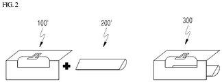
FIGS. 1 and2 are illustrative views each illustrating a structure in which an aperture antenna and a cavity structure according to an embodiment of the present disclosure are coupled to each other; -
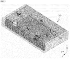
FIG. 3 is a perspective view illustrating a structure of a vertical polarization antenna according to an embodiment of the present disclosure; -
FIG. 4 is a plan view illustrating the structure of the vertical polarization antenna according to an embodiment of the present disclosure; -
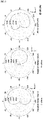
FIG. 5 is a view illustrating radiation patterns implemented in the vertical polarization antenna according to an embodiment of the present disclosure; -
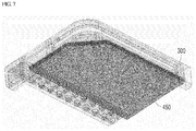
FIGS. 6 and7 are illustrative views illustrating the usage of a vertical polarization antenna of the present disclosure by being applied to a slim planar structure (e.g., a terminal); and -
FIG. 8 is a block diagram illustrating the configuration of a terminal device according to an embodiment of the present disclosure. - Hereinafter, some embodiments of the present disclosure will be described in detail with reference to illustrative drawings. In addition, in adding reference numerals to the components in each of the drawings, it shall be noted that like components are denoted by like reference numerals even if the components are illustrated in different drawings. In the following description of the present disclosure, a detailed description for known functions and configurations incorporated herein will be omitted when it is determined that the detailed description may make the subject matter of the present disclosure rather unclear.
- The present disclosure is to propose a vertical polarization antenna that is applicable to a slim planar structure of a terminal in a mobile communication system, such as a smartphone or a tablet PC, and more particularly, an ultra-high frequency band (mmWave band) vertical polarization antenna structure.
- A 5G communication system uses an ultra-high frequency band (mmWave band) compared to the frequency band currently used in an LTE (4G) communication system.
- Due to the propagation characteristic of radio waves in the air, signal attenuation occurs between counterpart transmission and reception terminals when polarization loss occurs.
- Meanwhile, in a mobile communication system, counterpart transmission and reception terminals may be considered as a base station and a terminal.
- Unlike an antenna of a base station having a fixed position, a terminal antenna whose position coordinates are always variable may cause a serious level of signal attenuation when polarization loss occurs due to a change in the position coordinates.
- In particular, polarization loss caused due to rotation in the theta direction (position coordinate change) of the terminal antenna may even cause a situation in which actual communication is lost (a wireless link loss situation) in the ultra-high frequency band (mmWave band) having strong linearity.
- Accordingly, in a 5G mobile communication system using the ultra-high frequency band (mmWave band), it is important to design a terminal antenna such that polarization loss does not occur even when a terminal moves variously and the position coordinates of the terminal antenna changes accordingly.
- Meanwhile, vertically polarized waves undergo relatively small signal attenuation compared to horizontally polarized waves for the same propagation distance. Thus, it is necessary to apply a vertical polarization antenna to a terminal in a mobile communication system.
- Consequently, in a 5G mobile communication system using an ultra-high frequency band (mmWave band), it may be considered to apply various polarization antennas such as a horizontal polarization antenna to a terminal, but it may be said that it is essential to apply a vertical polarization antenna designed to prevent polarization loss to a terminal.
- Terminals in mobile communication systems, such as smartphones and tablet PCs, are designed to have a planar structure having a very small height compared to a width, and will develop into a slimmer planar structure having a smaller height in the future.
- Meanwhile, a vertical polarization antenna has a limitation in height rather than width due to its structural characteristics.
- Accordingly, the existing ultra-high frequency band (mmWave band) vertical polarization antenna having an end-fire radiation pattern suitable for a mobile communication environment has a disadvantage in terms of height to be applied to a terminal having a slim planar structure.
- Accordingly, the present disclosure proposes a ultra-high frequency band (mmWave band) vertical polarization antenna having a new structure having an end-fire radiation pattern and being applicable to a slim planar structure (e.g., a terminal).
- Hereinafter, a vertical polarization antenna having a new structure proposed by the present disclosure will be described in detail with reference to
FIGS. 1 to 3 . - First, a coupling structure of a vertical polarization antenna according to an embodiment of the present disclosure will be described with reference to
FIG. 1 . - As illustrated in
FIG. 1 , avertical polarization antenna 300 according to an embodiment of the present disclosure includes: anaperture antenna 100, which is a flat conductor plate having an aperture formed therein, wherein the aperture has a shape bent along a bending line extending in the lengthwise direction thereof and the aperture antenna is configured to radiate vertically polarized waves through the aperture; and acavity structure 200 coupled to the rear side of theaperture antenna 100. - That is, the
vertical polarization antenna 300 of the present disclosure is implemented in a structure in which thecavity structure 200 is coupled to the rear side of theaperture antenna 100. - For convenience of description, hereinafter, in a three-dimensional space represented by x, y, and z axes, the two-dimensional space defined by the x axis and the y axis will be regarded as a ground, and the direction perpendicular to the ground (x axis, y axis) will be regarded as the z-axis direction.
- The shape of the
aperture antenna 100 in thevertical polarization antenna 300 of the present disclosure will be described below. - Assuming a shape obtained by vertically erecting a flat conductor plate having an aperture having a predetermined length and width without bending, vertically polarized waves will be radiated back and forth through the aperture in a planar shape.
- As illustrated in
FIG. 1 , thevertical polarization antenna 300 of the present disclosure is designed to have a shape obtained by bending the flat conductor plate along a bending line extending in the lengthwise direction of the aperture from the shape obtained by vertically erecting the flat conductor plate as assumed above. - In the
aperture antenna 100, the flat conductor plate (110a, 110b) is divided into atop surface 110a and afront surface 110b with reference to a bending line, and the bent aperture (130a, 130b) may be divided into atop surface 130a and aside surface 130b with reference to the bending line. - As noted from
FIG. 1 , thefront surface 110b of the flat conductor plate and theside surface 130b of the aperture are still erected in the vertical direction (z axis), and thetop surface 110a of the flat conductor plate and thetop surface 130a of the aperture have a structure that is bent from the vertical direction (z axis) to be laid down along the ground (x axis, y axis). - Then, in the
vertical polarization antenna 300 of the present disclosure, theaperture antenna 100 includes apower feeder 120 configured to feed power to the aperture in the center of thetop surface 130a of the aperture. - The
power feeder 120 will be described in more detail in the following description. - In this case, the
aperture antenna 100 may radiate vertically polarized waves, through the aperture, in the front-rear direction, that is, forward (in the +y-axis direction) and rearward (in the -y-axis direction) during power feeding from thepower feeder 120. - As described above, in the
vertical polarization antenna 300 of the present disclosure, since theaperture antenna 100 is designed/implemented to have a shape obtained by bending the flat conductor plate along the bending line extending in the lengthwise direction thereof, it is possible to minimize the height of the antenna structure while maintaining an electric field distribution that radiates vertically polarized waves back and forth, compared to the shape in which the above-described flat conductor plate is erected in the vertical direction. - The
cavity structure 200 is coupled to the rear side of theaperture antenna 100 to block the propagation of rearward radiation through the aperture in theaperture antenna 100. - That is, the
cavity structure 200 is designed as a structure capable of blocking the propagation of vertically polarized waves unnecessarily radiated rearward from theaperture antenna 100 when thecavity structure 200 is coupled to the rear side of theaperture antenna 100, thereby implementing forward-oriented vertical polarization radiation in thevertical polarization antenna 300. - Furthermore, the
cavity structure 200 has a structure such that rearward radiation through the aperture resonates within thecavity structure 200 and is coupled to forward radiation through the aperture. - That is, the
cavity structure 200 is designed as a structure that blocks the rearward radiation of theaperture antenna 100 when thecavity structure 200 is coupled to the rear side of theaperture antenna 100, and that cause vertically polarized waves of rearward radiation to resonate within thecavity structure 200 so as to be coupled to the forward radiation of theaperture antenna 100, thereby implementing vertical polarization radiation having a stronger forward-oriented end-fire pattern in thevertical polarization antenna 300. - The
cavity structure 200 may be designed in any structure as long as thecavity structure 200 is capable of blocking rear radiation of theaperture antenna 100 when the cavity structure is coupled to the rear side of theaperture antenna 100 and is capable of causing vertically polarized waves of rearward radiation to resonate within thecavity structure 200 so as to be coupled to the forward radiation of theaperture antenna 100. - An example of the shape of the
cavity structure 200 will be described below with reference toFIG. 1 . - The
cavity structure 200 includes abottom surface 210 facing thetop surface 110a of the flat conductor plate when coupled to the rear side of theaperture antenna 100, arear surface 220 facing thefront surface 110b of the flat conductor plate, and opposite side surfaces 230 and 240 connected to thebottom surface 210 and therear surface 220 of thecavity structure 200 to face each other. - At this time, in the embodiment of
FIG. 1 , thebottom surface 210, therear surface 220, and the opposite side surfaces 230 and 240 each have a flat shape, and may be connected to each other in an angled form (e.g., at a right angle). - As described above, since the
cavity structure 200 is designed as a structure that prevents rearward radiation from escaping out of thecavity structure 200 based on thebottom surface 210, therear surface 220, and the opposite side surfaces 230 and 240, the rearward radiation of theaperture antenna 100 is capable of resonating in thecavity structure 200 so as to be coupled to the forward radiation of theaperture antenna 100. - Meanwhile, another example of the shape of a cavity structure 200' will be described below with reference to
FIG. 2 . - The cavity structure 200' also includes a bottom surface facing the
top surface 110a of the flat conductor plate when coupled to theaperture antenna 100, a rear surface facing thefront surface 110b of the flat conductor plate, and opposite side surfaces connected to the bottom surface and the rear surface of the cavity structure 200' to face each other. - At this time, in the embodiment of
FIG. 2 , the bottom surface, the rear surface, and the opposite side surfaces of the cavity structure 200' each have a curved shape, and may be connected to each other in a curved form. - Of course, the bottom surface, the rear surface, and the opposite side surfaces of the cavity structure 200' may be interconnected in the state in which some of the surfaces have a flat shape and the others have a curved shape.
- That is, since the cavity structure 200' is designed as a structure that prevents rearward radiation from escaping out of the cavity structure 200' based on the bottom surface, the rear surface, and the opposite side surfaces, the rearward radiation of the
aperture antenna 100 is capable of resonating in the cavity structure 200' so as to be coupled to the forward radiation of theaperture antenna 100. - As described above, in the
vertical polarization antenna 300 of the present disclosure, thecavity structure 200 or 200' is designed/implemented in a structure that allows the rearward radiation of theaperture antenna 100 to resonate and to be coupled to forward radiation, thereby enabling stronger forward-oriented end-fire pattern vertical polarization radiation in thevertical polarization antenna 300 or 300'. - Hereinafter, a vertical polarization antenna according to an embodiment of the present disclosure will be described from various viewpoints with reference to
FIGS. 3 and4 . - However, for convenience of description, the shape of the
cavity structure 200 illustrated inFIG. 1 will be described. -
FIG. 3 is a perspective view of thevertical polarization antenna 300 of the present disclosure as viewed isometrically from a side, andFIG. 4 is a plan view of thevertical polarization antenna 300 of the present disclosure viewed from above. - The length Ls of the
apertures aperture antenna 100 means the length of the aperture in a planar form from the viewpoint of the flat conductor flat plate (110a, 110b). - In addition, when the width Wh of the
side surface 130b and the width Ws of thetop surface 130a are summed in the aperture (130a, 130b), it means the width of the aperture in a planar form from the viewpoint of the conductor flat plate (110a, 110b). - As noted from
FIGS. 2 and3 , the width Ws of the top surface 103a is designed to be wider than the width Wh of theside surface 130b in the aperture (130a, 130b). - In addition, opposite edges of the
side surface 130b in the aperture (130a, 130b) may have an angled shape, and according to an example, the opposite edges of theside surface 130b may have a right-angle shape. - In addition, opposite edges of the top surface 103a in the aperture (130a, 130b) may be curved.
- As illustrated in
FIGS. 3 and4 , apower feeder 120 configured to feed power to the aperture (130a, 130b) is provided in the center of thetop surface 130a of the aperture in theaperture antenna 100. - The
power feeder 120 may be in a form in which a ground signal ground (GSG) tablet PC is set on thetop surface 110a of the flat conductor plate to be capable of being easily surface-mounted with a communication chip (not illustrated). - The
power feeder 120 includes apower feeding line 122 formed to extend in the direction of the bending line on thetop surface 110a of the flat conductor plate, and aconverter 124 formed to extend in the direction of the length Ls of the aperture (130a, 130b) and configured to store electricity applied from thepower feeding line 122 and to convert the electricity into a magnetic field. - The
power feeding line 122 of thepower feeder 120 may provide an inductive power feeding function, and theconverter 120 of thepower feeder 124 may provide a capacitive power feeding function. - Thus, in the
power feeder 120, when electricity (current) is applied to theconverter 124 from a communication chip (not illustrated) connected to the other end of thepower feeding line 122, the electricity (current) will be stored in theconverter 124 extending in the direction of the length Ls of the aperture (130a, 130b). - In the
power feeder 120, the magnetic field generated due to the electricity (current) stored in theconverter 124 is formed in the downward vertical direction from theside surface 130b of the aperture, that is, in the -z-axis direction while being radiated from theconverter 124 formed to extend in the direction of the length Ls of the aperture (130a, 130b). - As described above, the width Ws of the
top surface 130a is wider than the width Wh of theside surface 130b in the aperture (130a, 130b), the opposite edges of thetop surface 130a have a curved shape, and the opposite edges of theside surface 130b have an angled shape (e.g., a right angle). Thus, among magnetic fields radiated from theconverter 124, the propagation distances of the magnetic fields propagating/reflected on the opposite sides along thetop surface 130a of the aperture to propagate in the -z-axis direction on thetop surface 130a are shortened, and all the magnetic fields propagating in the -z-axis direction are made to propagate by the same distance on theside surface 130b. - That is, by designing the width Ws of the
top surface 130a to be wider than the width Wh of theside surface 130b in the aperture (130a, 130b), and designing the opposite edges of thetop surface 130a in a curved shape and the opposite edges of theside surface 130b in an angled shape (e.g., a right angle), it is possible to minimize/optimize an internal resistance (reflection) component that may occur during the magnetic field formation process in which the magnetic field is formed by thepower feeder 120. - Then, in the
vertical polarization antenna 300 of the present disclosure, theaperture antenna 100 may radiate vertically polarized waves forward and rearward, i.e., in the +y-axis direction and in the -y-axis direction, which are generated by magnetic fields formed in the -z-axis direction from the aperture, and in particular, from theside surface 130b of the aperture when power is fed from thepower feeder 120. - At this time, the resonance frequency of the vertically polarized waves radiated from the
aperture antenna 100 is determined depending on the width Wh of thetop surface 130a of the aperture and the length Ls of the aperture. - Meanwhile, the
cavity structure 200 is capable of adjusting the position of a resonance point (resonance frequency) by adjusting the width Wc and length Lc of thecavity structure 200. - Accordingly, the
cavity structure 200 may be designed to have a structure of the length Lc and width Wc that makes the resonance frequency in thecavity structure 200 identical to the resonance frequency in theaperture antenna 100 such that the rearward radiation of theaperture antenna portion 100 can be coupled to the resonance and the forward radiation. - Then, in the
vertical polarization antenna 300 of the present disclosure, thecavity structure 200 enables vertical polarization radiation of a stronger front-oriented end-fire pattern by allowing the rearward radiation of theaperture antenna 100 to be coupled to the resonance and the forward radiation at the same resonance frequency as theaperture antenna 100. - As described above, the
vertical polarization antenna 300 of the present disclosure is implemented as a structure in which theaperture antenna 100, which is designed to have a shape that minimizes the height of the antenna structure, and thecavity structure 200, which is designed to have a structure that enables vertical polarization radiation of a strong forward-oriented end-fire pattern in theaperture antenna 100, are coupled to each other. -
FIG. 5 is an illustrative view illustrating radiation patterns actually implemented in a vertical polarization antenna according to an embodiment of the present disclosure. - Referring to an E-plane radiation pattern obtained by viewing the
vertical polarization antenna 300 of the present disclosure from a lateral side, it can be seen that radio waves (polarized waves) radiated from thevertical polarization antenna 300 exhibit vertical polarization characteristics in the end-fire direction (boresight at theta - 90°). - That is, the
vertical polarization antenna 300 of the present disclosure has a vertical polarization characteristic of an end-fire pattern. - Referring to an H-plane radiation pattern obtained by viewing the
vertical polarization antenna 300 of the present disclosure from a top side, it can be seen that, in radio waves (polarized waves) radiated from thevertical polarization antenna 300, there is a difference of about 12dB or more in magnitude between the forward radiation and the rearward radiation. - That is, the
vertical polarization antenna 300 of the present disclosure has a stronger forward-oriented high front-to-back ratio characteristic. - In addition, referring to a co-polarization (Co-pol) radiation pattern and a cross polarization (X-pol) pattern in the
vertical polarization antenna 300 of the present disclosure, a difference of about 50 dB or more in the magnitude of magnetic field can be observed between the co-polarization and the cross polarization in thevertical polarization antenna 300. - That is, the
vertical polarization antenna 300 of the present disclosure has a low cross polarization characteristic. - As noted from the above, the present disclosure implements an ultra-high frequency band (mmWave band) vertical polarization antenna having a new structure improved in antenna performance, i.e., a front-to-back ratio characteristic and a low cross polarization characteristic while dramatically minimizing the height of the antenna structure.
-
FIGS. 6 and7 are illustrative views illustrating the usage of a vertical polarization antenna of the present disclosure by being applied to a slim planar structure (e.g., a terminal). - Since the
vertical polarization antenna 300 proposed by the present disclosure has a flat shape structurally having a very small height compared to the width thereof, thevertical polarization antenna 300 has a structural advantage suitable for application to a slim flat structure, such as a terminal in a mobile communication system, such as a smartphone or a tablet PC. - In addition, the
vertical polarization antenna 300 proposed by the present disclosure can be used in a multi-input multi-output (MIMO) beamforming system of an ultra-high frequency band (mmWave band). - As noted from
FIGS. 6 and7 , by arranging/placing a plurality ofvertical polarization antennas 300 of the present disclosure at the edges of a circuit board 450 (e.g., a PCB, an FPCB, or an LTCC) of a slim planar structure (e.g., a terminal), it is possible to minimize the placement space. - In particular, as noted from
FIG. 6 , thanks to the above structural advantages, thevertical polarization antenna 300 of the present disclosure can be placed on acircuit board 450, on which an RF component required in a MIMO beamforming system is placed, to be coplanar with the RF component. - As described above, when it is possible to place (position) the
vertical polarization antenna 300 of the present disclosure on the same plane as the RF component, it is possible to expect an effect of having a margin in selection of resolution of a phase shifter. - In addition, thanks to the above structural advantages, the
vertical polarization antenna 300 proposed by the present disclosure can be disposed, on the same plane, together with broadside radiation elements of a patch antenna or the like, in which case it is possible to expect an effect of facilitating expansion of a beam coverage. - Furthermore, thanks to the above structural advantages, the
vertical polarization antenna 300 proposed by the present disclosure can be disposed together with a horizontal polarization antenna on the same plane, in which case it is possible to expect an effect of being applicable to a dual polarization antenna system or the like. - A
transceiver 421, aphase shifter 422, a switch, and a power divider/combiner 423 may be implemented in the form of a chip or package. - Meanwhile, although omitted from
FIG. 6 for the sake of simplicity, a transmission/reception processor (RFIC) 420 implemented in the form of a chip or a package in the state of including thetransceiver 421, thephase shifter 422, the switch, and the power divider/combiner 423 may further include a modulator, a demodulator, a synthesizer, a local oscillator (LO), a digital-to-analog converter (DAC), an analog-to-digital converter (ADC), and the like. - As noted from the above, in the present disclosure, by implementing an ultra-high frequency band (mmWave band)
antenna 300 having a new structure improved in antenna performance, i.e., a front-to-back ratio characteristic and a low cross polarization characteristic, it is possible to obtain an effect of being freely applicable to a slim planar structure (e.g., a terminal). - Hereinafter, the configuration of a terminal device according to an embodiment of the present disclosure will be described with reference to
FIG. 8 . - The
terminal device 400 according to an embodiment of the present disclosure includes anantenna unit 410 including a plurality of antennas, and a transmission/reception processor 420 configured to process signals transmitted/received through theantenna unit 410. - In addition, the
terminal device 400 according to an embodiment of the present disclosure may further include acommunication processor 430. - The
communication processor 430 transmits, to the transmission/reception processor 420, a signal to be transmitted through theantenna unit 410, and receives a signal received and processed by the transmission/reception processor 420, through theantenna unit 410. - The
communication processor 430 may be a MIMO baseband. - In addition, the
communication processor 430 may control the phase and amplitude of thephase shifter 422 and/or a variable gain amplifier connected to each antenna channel formed in theantenna unit 410 so as to adjust the beam shape (direction/shape) of an antenna beam for signal transmission and reception. - The beam shape adjustment method described above is an analog beam forming method.
- In addition to the above-described analog beam forming method, the terminal device of the present disclosure may also adopt a hybrid beam forming method, in which a digital beam forming method, an analog beam forming method, and a digital beam forming method performed by the
communication processor 430 stage are combined. - The transmission/
reception processor 420 processes a signal received from thecommunication processor 430 so as to transmit the processed signal through an antenna beam formed in a specific direction by theantenna unit 410, and processes a signal received from theantenna unit 410 through an antenna beam formed in a specific direction so as to transmit the processed signal to thecommunication processor 430. - The transmission/
reception processor 420 is a functional unit (e.g., an RFIC) including an RF component required in a MIMO beamforming system. - Referring to
FIG. 6 , the transmission/reception processor 420 may include atransceiver 421, aphase shifter 422, a switch, and a power divider/combiner 423, and may further include a modulator, a demodulator, a synthesizer, a local oscillator (LO), a digital-to-analog converter (DAC), an analog to digital converter (ADC), and the like. - Accordingly, if the
terminal device 400 adopts a direct conversion method, theterminal device 400 may be provided with the transmission/reception processor 420 in the form of a single RFIC. - In this case, during uplink, the transmission/
reception processor 420 may process a baseband signal received from thecommunication processor 430 as a signal in a millimeter wave band (about 20 to 60 GHz), and may then transmit the signal through an antenna beam formed in a specific direction in theantenna unit 410. - Meanwhile, during downlink, the transmission/
reception processor 420 may process a signal received through the antenna beam formed in the specific direction in theantenna unit 410, and may then transmit the signal to thecommunication processor 430. - In contrast, if the
terminal device 400 adopts a heterodyne method using an IF frequency (about 8 to 10 GHz), theterminal device 400 may be provided with two RFIC types of transmission/reception processors 420. - In this case, the transmission/
reception processor 420 is divided into two RFICs (e.g., a first RFIC and a second RFIC), and during uplink, when the first RFIC of the transmission/reception processor 420 converts a baseband signal received from thecommunication processor 430 into a signal having an IF frequency (about 8 to 10 GHz) and transmits the signal, the second RFIC of the transmission/reception processor 420, which receives the signal, may convert the signal into a signal in a mmWave band (about 20 to 60 GHz) and may then transmit the signal through an antenna beam formed in a specific direction in theantenna unit 410. - Meanwhile, during downlink, when the second RFIC of the transmission/
reception processor 420 converts the signal received through the antenna beam formed in the specific direction in theantenna unit 410 into a signal having an IF frequency (about 8 to 10 GHz), the first RFIC of the transmission/reception processor 420, which receives the signal, may process the signal and may then transmit the signal thecommunication processor 430. - Each of multiple antennas constituting the antenna unit 410 (e.g.,
antenna 1,antenna 2, ..., and antenna N) includes the above-described vertical polarization antenna of the present disclosure. - That is, as described above, the multiple antennas constituting the
antenna unit 410 may be arranged in a form arranged along the edges of a circuit board (e.g., 450 inFIG. 6 ) provided in theterminal device 400. - In
FIG. 6 , for convenience of description, only a portion (e.g., the upper left portion) of thecircuit board 450 is illustrated, but the multiple antennas constituting theantenna unit 410 may be arranged/placed along each of upper, lower, left, and right edges of thecircuit board 450 provide in theterminal device 400. - As described above, the
terminal device 400 according to an embodiment of the present disclosure, in particular, theterminal device 400 employing the MIMO beamforming technology in the ultra-high frequency band (mmWave band) is capable of minimizing the space for theantenna unit 410 by arranging/placing multiplevertical polarization antennas 300 in the ultra-high frequency band (mmWave band) having a new structure (structural advantage) improved in antenna performance, that is, a front-to-back ratio characteristic and a low cross polarization characteristic while dramatically minimizing the height of the antenna structure. - In particular, thanks to the above-described structural advantages of the
vertical polarization antenna 300, theantenna unit 410 of theterminal device 400 according to an embodiment of the present disclosure can be placed on thecircuit board 450, on which an RF component, that is, the transmission/reception processor 420, is disposed. Thus, it is possible to expect an effect of having a margin on selection of resolution of a phase shifter. - In addition, thanks to the above-described structural advantages of the
vertical polarization antenna 300, theantenna unit 410 of theterminal device 400 according to an embodiment of the present disclosure and broadside radiation elements of a patch antenna or the like can be arranged on the same plane. Thus, it is possible to expect an effect of facilitating expansion of a beam coverage. - Furthermore, thanks to the above-described structural advantages of the
vertical polarization antenna 300, theterminal device 400 according to an embodiment of the present disclosure may place theantenna unit 410 and a horizontal polarization antenna together on the same plane, in which case it is also possible to expect an effect of adopting a dual polarization antenna system - Furthermore, in the
terminal device 400 according to an embodiment of the present disclosure, by arrangingvertical polarization antennas 300 having a structural advantage of improving the antenna performance while dramatically minimizing the height thereof along each of the upper, lower, left, and right edges of thecircuit board 450, it is possible to arrange/place a larger number ofvertical polarization antennas 300 compared to the conventional ones. - Therefore, in the
terminal device 400 according to an embodiment of the present disclosure, with respect to a large number ofvertical polarization antennas 300 provided thereto, based on a channel state of each antenna channel and the remaining battery power of the terminal device, it is possible to diversify/implement an algorithm for optimally selecting at least onevertical polarization antenna 300 to be used for signal transmission/reception. - In addition, in the
terminal device 400 according to an embodiment of the present disclosure, among a large number ofvertical polarization antennas 300 provided thereto, based on a channel state of each antenna channel and the remaining battery power of theterminal device 400, it is possible to diversify/implement an algorithm for optimally controlling the operation of remainingvertical polarization antennas 300 that are not selected for use in transmission/reception. - For example, in the
terminal device 400, when the remaining battery power is less than a threshold, power consumption can be reduced by turning off the remainingvertical polarization antennas 300 that are not selected for use in signal transmission/reception. - In addition, in the
terminal device 400, when the remaining battery power is not below a threshold, it is possible to further select some of the remainingvertical polarization antennas 300 depending on the channel state of thevertical polarization antennas 300 being used for signal transmission/reception so as to use the selected ones for spatial diversity technology, or to select at least onevertical polarization antenna 300 to be used for spatial multiplexing technology among the remainingvertical polarization antennas 300 so as to simultaneously operate different communication channels. - The subject of the selection and operation control algorithm described above may be a
communication processor 430, that is, a MIMO baseband, or a separate functional unit (not illustrated). - In the foregoing, the present disclosure has been described in detail with reference to embodiments, but the present disclosure is not limited to the above-described embodiments. The technical spirit of the present disclosure will cover various modifications and changes that can be made by a person ordinarily skilled in the art to which the present disclosure belongs without departing from the gist of the present disclosure claimed in the following claims
Claims (15)
- A vertical polarization antenna comprising:an aperture antenna, which is a flat conductor plate having an aperture, is configured to radiate vertically polarized wave through the aperture, the aperture having a shape bent along a bending line extending in a lengthwise direction of the aperture antenna; anda cavity structure coupled to a rear side of the aperture antenna.
- The vertical polarization antenna of claim 1, wherein the cavity structure is configured to block propagation of rearward radiation through the aperture.
- The vertical polarization antenna of claim 1, wherein the cavity structure is configured to cause the rearward radiation through the aperture to resonate within a cavity formed by the cavity structure so as to be coupled to forward radiation through the aperture.
- The vertical polarization antenna of claim 1, wherein the aperture includes a top surface and a side surface with reference to the bending line, and
the aperture antenna includes a power feeder in a center area of the top surface of the aperture. - The vertical polarization antenna of claim 4, wherein the power feeder includes a power feeding line extending on the flat conductor plate toward the bending line and a converter extending in the lengthwise direction of the aperture.
- The vertical polarization antenna of claim 5, wherein the converter is configured to store electricity applied from the power feeding line and to convert the electricity into a magnetic field.
- The vertical polarization antenna of claim 1, wherein the aperture includes a top surface and a side surface with reference to the bending line, and
the top surface of the aperture has a width larger than a width of the side surface of the aperture. - The vertical polarization antenna of claim 7, wherein edges of the side surface of the aperture have an angled shape, and
edges of the top surface of the aperture have a curved shape. - The vertical polarization antenna of claim 1, wherein the aperture includes a top surface and a side surface with reference to the bending line, and
the aperture antenna has a resonance frequency that is determined depending on a width of the top surface of the aperture and a length of the aperture. - The vertical polarization antenna of claim 1, wherein the flat conductor plate includes a top surface and a front surface with reference to the bending line, and
the cavity structure includes a bottom surface facing the top surface of the flat conductor plate, a rear surface facing the front surface of the flat conductor plate, and side surfaces connected to the bottom surface and the rear surface of the cavity structure and facing each other. - The vertical polarization antenna of claim 10, wherein each of the bottom surface, the rear surface, and the side surfaces has a planar shape or a curved shape.
- The vertical polarization antenna of claim 3, wherein the cavity structure has a length and a width that make a resonance frequency within the cavity equal to a resonance frequency of the aperture antenna.
- A terminal device comprising:an antenna; anda transmission/reception processor configured to process a signal transmitted/received through the antenna;wherein the antenna includes:an aperture antenna, which is a flat conductor plate having an aperture, is configured to radiate vertically polarized wave through the aperture, the aperture having a shape bent along a bending line extending in a lengthwise direction of the aperture antenna; anda cavity structure coupled to a rear side of the aperture antenna.
- The terminal device of claim 13, wherein a plurality of antennas are arranged along an outer edge of a circuit board on which the transmission/reception processor is disposed.
- The terminal device of claim 14, wherein the plurality of antennas are positioned on a same plane as the transmission/reception processor.
Applications Claiming Priority (2)
| Application Number | Priority Date | Filing Date | Title |
|---|---|---|---|
| KR1020180007336A KR101985686B1 (en) | 2018-01-19 | 2018-01-19 | Vertical polarization antenna |
| PCT/KR2019/000646 WO2019143126A1 (en) | 2018-01-19 | 2019-01-16 | Vertical polarized antenna and terminal device |
Publications (3)
| Publication Number | Publication Date |
|---|---|
| EP3742553A1 true EP3742553A1 (en) | 2020-11-25 |
| EP3742553A4 EP3742553A4 (en) | 2021-09-29 |
| EP3742553B1 EP3742553B1 (en) | 2023-11-15 |
Family
ID=66810975
Family Applications (1)
| Application Number | Title | Priority Date | Filing Date |
|---|---|---|---|
| EP19741478.2A Active EP3742553B1 (en) | 2018-01-19 | 2019-01-16 | Vertical polarized antenna and terminal device |
Country Status (5)
| Country | Link |
|---|---|
| US (1) | US11637380B2 (en) |
| EP (1) | EP3742553B1 (en) |
| KR (1) | KR101985686B1 (en) |
| CN (1) | CN111615775B (en) |
| WO (1) | WO2019143126A1 (en) |
Families Citing this family (2)
| Publication number | Priority date | Publication date | Assignee | Title |
|---|---|---|---|---|
| CN112103624B (en) * | 2020-09-16 | 2022-11-15 | Oppo(重庆)智能科技有限公司 | Antenna device and electronic apparatus |
| CN116365243A (en) * | 2021-10-15 | 2023-06-30 | 荣耀终端有限公司 | Resonant cavity antenna and electronic equipment |
Family Cites Families (50)
| Publication number | Priority date | Publication date | Assignee | Title |
|---|---|---|---|---|
| US2972147A (en) * | 1958-07-09 | 1961-02-14 | Sylvania Electric Prod | Circularly polarized slot antenna |
| US2946055A (en) * | 1958-12-29 | 1960-07-19 | Sylvania Electric Prod | Parasitic dipole slot antenna |
| US3022505A (en) * | 1960-03-29 | 1962-02-20 | Glenn A Scharp | Loaded double-folded slot antenna |
| US4242685A (en) * | 1979-04-27 | 1980-12-30 | Ball Corporation | Slotted cavity antenna |
| FR2481526A1 (en) * | 1980-04-23 | 1981-10-30 | Trt Telecom Radio Electr | ANTENNA WITH THIN STRUCTURE |
| FR2582864B1 (en) * | 1985-06-04 | 1987-07-31 | Labo Electronique Physique | MICROWAVE UNIT MODULES AND MICROWAVE ANTENNA COMPRISING SUCH MODULES |
| EP0295003A3 (en) * | 1987-06-09 | 1990-08-29 | THORN EMI plc | Antenna |
| US5194876A (en) * | 1989-07-24 | 1993-03-16 | Ball Corporation | Dual polarization slotted antenna |
| DE69127751T2 (en) * | 1990-06-14 | 1998-04-30 | John Louis F Ch Collins | ANTENNA IN THE FORM OF A FLAT PLATE |
| KR100355263B1 (en) * | 1995-09-05 | 2002-12-31 | 가부시끼가이샤 히다치 세이사꾸쇼 | Coaxial Resonant Slot Antenna, Manufacturing Method and Portable Wireless Terminal |
| US6064350A (en) * | 1997-07-25 | 2000-05-16 | Kyocera Corporation | Laminated aperture-faced antenna and multi-layered wiring board comprising the same |
| US6198437B1 (en) * | 1998-07-09 | 2001-03-06 | The United States Of America As Represented By The Secretary Of The Air Force | Broadband patch/slot antenna |
| US6166701A (en) * | 1999-08-05 | 2000-12-26 | Raytheon Company | Dual polarization antenna array with radiating slots and notch dipole elements sharing a common aperture |
| EP1158605B1 (en) * | 2000-05-26 | 2004-04-14 | Sony International (Europe) GmbH | V-Slot antenna for circular polarization |
| US6307520B1 (en) * | 2000-07-25 | 2001-10-23 | International Business Machines Corporation | Boxed-in slot antenna with space-saving configuration |
| US6646618B2 (en) * | 2001-04-10 | 2003-11-11 | Hrl Laboratories, Llc | Low-profile slot antenna for vehicular communications and methods of making and designing same |
| US6859186B2 (en) * | 2003-02-03 | 2005-02-22 | Silver Spring Networks, Inc. | Flush-mounted antenna and transmission system |
| EP1521332B1 (en) * | 2003-09-30 | 2007-08-15 | Lucent Technologies Network Systems GmbH | A compact multiple-band antenna arrangement |
| JP4409257B2 (en) * | 2003-11-18 | 2010-02-03 | シャープ株式会社 | Radio tag, article provided with the same, and RFID system |
| US7388550B2 (en) * | 2005-10-11 | 2008-06-17 | Tdk Corporation | PxM antenna with improved radiation characteristics over a broad frequency range |
| WO2007058230A1 (en) * | 2005-11-18 | 2007-05-24 | Nec Corporation | Slot antenna and portable wireless terminal |
| KR100788284B1 (en) | 2005-11-24 | 2007-12-27 | 엘지전자 주식회사 | Electronic equipment with broadband antenna and broadband antenna |
| CN101013774A (en) * | 2007-02-14 | 2007-08-08 | 东南大学 | Slot patch printing antenna of coplanar waveguide feed |
| US20090153412A1 (en) * | 2007-12-18 | 2009-06-18 | Bing Chiang | Antenna slot windows for electronic device |
| US7804453B2 (en) * | 2008-04-16 | 2010-09-28 | Apple Inc. | Antennas for wireless electronic devices |
| US8174452B2 (en) * | 2008-09-25 | 2012-05-08 | Apple Inc. | Cavity antenna for wireless electronic devices |
| US8269677B2 (en) * | 2009-09-03 | 2012-09-18 | Apple Inc. | Dual-band cavity-backed antenna for integrated desktop computer |
| JP5413467B2 (en) | 2010-01-27 | 2014-02-12 | 株式会社村田製作所 | Broadband antenna |
| US8773310B2 (en) * | 2010-03-30 | 2014-07-08 | Apple Inc. | Methods for forming cavity antennas |
| US8542151B2 (en) * | 2010-10-21 | 2013-09-24 | Mediatek Inc. | Antenna module and antenna unit thereof |
| US8514138B2 (en) * | 2011-01-12 | 2013-08-20 | Mediatek Inc. | Meander slot antenna structure and antenna module utilizing the same |
| US9755315B2 (en) * | 2011-02-10 | 2017-09-05 | Nokia Technologies Oy | Antenna arrangement |
| JP5408160B2 (en) * | 2011-03-09 | 2014-02-05 | 株式会社村田製作所 | Horizontal radiating antenna |
| US8970446B2 (en) * | 2011-07-01 | 2015-03-03 | Apple Inc. | Electronic device with magnetic antenna mounting |
| US9455489B2 (en) * | 2011-08-30 | 2016-09-27 | Apple Inc. | Cavity antennas |
| KR101255947B1 (en) | 2011-10-05 | 2013-04-23 | 삼성전기주식회사 | Dielectric resonant antenna adjustable bandwidth |
| US9318793B2 (en) * | 2012-05-02 | 2016-04-19 | Apple Inc. | Corner bracket slot antennas |
| EP2955787B1 (en) * | 2013-02-07 | 2019-08-14 | Mitsubishi Electric Corporation | Antenna device and array antenna device |
| US9450292B2 (en) * | 2013-06-05 | 2016-09-20 | Apple Inc. | Cavity antennas with flexible printed circuits |
| US9728858B2 (en) * | 2014-04-24 | 2017-08-08 | Apple Inc. | Electronic devices with hybrid antennas |
| JP6196188B2 (en) * | 2014-06-17 | 2017-09-13 | 株式会社東芝 | ANTENNA DEVICE AND RADIO DEVICE |
| KR102151425B1 (en) | 2014-08-05 | 2020-09-03 | 삼성전자주식회사 | Antenna device |
| KR102138909B1 (en) * | 2014-09-19 | 2020-07-28 | 삼성전자주식회사 | Antenna device and method for operation of the same |
| JP5824563B1 (en) * | 2014-09-22 | 2015-11-25 | 学校法人智香寺学園 | Small slot antenna |
| US9871299B2 (en) * | 2014-12-04 | 2018-01-16 | Qualcomm Incorporated | Cavity backed aperture antenna |
| US10873121B2 (en) * | 2016-02-05 | 2020-12-22 | Mitsubishi Electric Corporation | Antenna device |
| KR102275420B1 (en) | 2016-07-12 | 2021-07-09 | 한국전자통신연구원 | A method for encoding/decoding a video and a readable medium therefor |
| US10749264B2 (en) * | 2017-04-07 | 2020-08-18 | Microsoft Technology Licensing, Llc | Cavity-backed slot antenna |
| US11271296B2 (en) * | 2017-11-10 | 2022-03-08 | Texas Instruments Incorporated | Molded packaged antenna |
| CN112768884B (en) * | 2020-12-17 | 2023-10-03 | 深圳市南斗星科技有限公司 | Dual-polarized high-isolation indoor distribution antenna |
-
2018
- 2018-01-19 KR KR1020180007336A patent/KR101985686B1/en active Active
-
2019
- 2019-01-16 CN CN201980009027.8A patent/CN111615775B/en active Active
- 2019-01-16 EP EP19741478.2A patent/EP3742553B1/en active Active
- 2019-01-16 WO PCT/KR2019/000646 patent/WO2019143126A1/en not_active Ceased
- 2019-01-16 US US16/769,653 patent/US11637380B2/en active Active
Also Published As
| Publication number | Publication date |
|---|---|
| WO2019143126A1 (en) | 2019-07-25 |
| EP3742553B1 (en) | 2023-11-15 |
| US11637380B2 (en) | 2023-04-25 |
| CN111615775A (en) | 2020-09-01 |
| CN111615775B (en) | 2023-04-07 |
| US20210367345A1 (en) | 2021-11-25 |
| KR101985686B1 (en) | 2019-06-04 |
| EP3742553A4 (en) | 2021-09-29 |
Similar Documents
| Publication | Publication Date | Title |
|---|---|---|
| US12199347B2 (en) | Null steering antenna techniques for advanced communication systems | |
| CN110137675B (en) | Antenna unit and terminal equipment | |
| KR101852580B1 (en) | Antenna system loaded in vehicle | |
| US11367943B2 (en) | Patch antenna unit and antenna in package structure | |
| US20100007573A1 (en) | Multibeam antenna | |
| US11735819B2 (en) | Compact patch and dipole interleaved array antenna | |
| US7812768B2 (en) | Multiple input multiple output antenna | |
| US20230113751A1 (en) | Antenna, antenna assembly, and wireless communication device | |
| EP3685512B1 (en) | Antenna system for a wireless communication device | |
| CN108199128A (en) | A kind of antenna system and mobile terminal | |
| CN104600422A (en) | Dual-polarization coaxial yagi antenna system | |
| US20240429611A1 (en) | Broadband patch antenna | |
| EP4425701A1 (en) | Antenna unit, antenna, and antenna feeder system | |
| US11637380B2 (en) | Vertical polarized antenna and terminal device | |
| US20260066547A1 (en) | Antenna structure and communication device | |
| US20220302595A1 (en) | Slanted polarization antenna | |
| WO2025236984A1 (en) | Antenna unit, base station antenna, and communication device | |
| US11888234B2 (en) | Zig-zag antenna array and system for polarization control | |
| KR102254173B1 (en) | Polarization antenna | |
| CN120691096A (en) | electronic devices | |
| CN110011028B (en) | Antenna system, communication terminal and base station | |
| CN116154472A (en) | Dual polarized antenna unit, antenna module and base station | |
| KR20160080037A (en) | High Gain Travelling Wave Antenna Not Requiring Impedance Matching Components | |
| EP4513676A1 (en) | Antenna and base station | |
| KR101309505B1 (en) | Mimo antenna |
Legal Events
| Date | Code | Title | Description |
|---|---|---|---|
| STAA | Information on the status of an ep patent application or granted ep patent |
Free format text: STATUS: THE INTERNATIONAL PUBLICATION HAS BEEN MADE |
|
| PUAI | Public reference made under article 153(3) epc to a published international application that has entered the european phase |
Free format text: ORIGINAL CODE: 0009012 |
|
| STAA | Information on the status of an ep patent application or granted ep patent |
Free format text: STATUS: REQUEST FOR EXAMINATION WAS MADE |
|
| 17P | Request for examination filed |
Effective date: 20200807 |
|
| AK | Designated contracting states |
Kind code of ref document: A1 Designated state(s): AL AT BE BG CH CY CZ DE DK EE ES FI FR GB GR HR HU IE IS IT LI LT LU LV MC MK MT NL NO PL PT RO RS SE SI SK SM TR |
|
| AX | Request for extension of the european patent |
Extension state: BA ME |
|
| DAV | Request for validation of the european patent (deleted) | ||
| DAX | Request for extension of the european patent (deleted) | ||
| A4 | Supplementary search report drawn up and despatched |
Effective date: 20210901 |
|
| RIC1 | Information provided on ipc code assigned before grant |
Ipc: H01Q 13/18 20060101ALI20210826BHEP Ipc: H01Q 13/16 20060101ALI20210826BHEP Ipc: H01Q 1/24 20060101ALI20210826BHEP Ipc: H01Q 13/10 20060101ALI20210826BHEP Ipc: H01Q 1/46 20060101ALI20210826BHEP Ipc: H01Q 9/18 20060101AFI20210826BHEP |
|
| RIC1 | Information provided on ipc code assigned before grant |
Ipc: H01Q 3/26 20060101ALI20230430BHEP Ipc: H01Q 13/18 20060101ALI20230430BHEP Ipc: H01Q 13/16 20060101ALI20230430BHEP Ipc: H01Q 1/24 20060101ALI20230430BHEP Ipc: H01Q 13/10 20060101ALI20230430BHEP Ipc: H01Q 1/46 20060101ALI20230430BHEP Ipc: H01Q 9/18 20060101AFI20230430BHEP |
|
| GRAP | Despatch of communication of intention to grant a patent |
Free format text: ORIGINAL CODE: EPIDOSNIGR1 |
|
| STAA | Information on the status of an ep patent application or granted ep patent |
Free format text: STATUS: GRANT OF PATENT IS INTENDED |
|
| INTG | Intention to grant announced |
Effective date: 20230627 |
|
| GRAS | Grant fee paid |
Free format text: ORIGINAL CODE: EPIDOSNIGR3 |
|
| P01 | Opt-out of the competence of the unified patent court (upc) registered |
Effective date: 20230905 |
|
| GRAA | (expected) grant |
Free format text: ORIGINAL CODE: 0009210 |
|
| STAA | Information on the status of an ep patent application or granted ep patent |
Free format text: STATUS: THE PATENT HAS BEEN GRANTED |
|
| AK | Designated contracting states |
Kind code of ref document: B1 Designated state(s): AL AT BE BG CH CY CZ DE DK EE ES FI FR GB GR HR HU IE IS IT LI LT LU LV MC MK MT NL NO PL PT RO RS SE SI SK SM TR |
|
| REG | Reference to a national code |
Ref country code: CH Ref legal event code: EP Ref country code: GB Ref legal event code: FG4D |
|
| REG | Reference to a national code |
Ref country code: DE Ref legal event code: R096 Ref document number: 602019041499 Country of ref document: DE |
|
| REG | Reference to a national code |
Ref country code: IE Ref legal event code: FG4D |
|
| REG | Reference to a national code |
Ref country code: LT Ref legal event code: MG9D |
|
| REG | Reference to a national code |
Ref country code: NL Ref legal event code: MP Effective date: 20231115 |
|
| PG25 | Lapsed in a contracting state [announced via postgrant information from national office to epo] |
Ref country code: GR Free format text: LAPSE BECAUSE OF FAILURE TO SUBMIT A TRANSLATION OF THE DESCRIPTION OR TO PAY THE FEE WITHIN THE PRESCRIBED TIME-LIMIT Effective date: 20240216 |
|
| PG25 | Lapsed in a contracting state [announced via postgrant information from national office to epo] |
Ref country code: IS Free format text: LAPSE BECAUSE OF FAILURE TO SUBMIT A TRANSLATION OF THE DESCRIPTION OR TO PAY THE FEE WITHIN THE PRESCRIBED TIME-LIMIT Effective date: 20240315 |
|
| PG25 | Lapsed in a contracting state [announced via postgrant information from national office to epo] |
Ref country code: LT Free format text: LAPSE BECAUSE OF FAILURE TO SUBMIT A TRANSLATION OF THE DESCRIPTION OR TO PAY THE FEE WITHIN THE PRESCRIBED TIME-LIMIT Effective date: 20231115 |
|
| REG | Reference to a national code |
Ref country code: AT Ref legal event code: MK05 Ref document number: 1632637 Country of ref document: AT Kind code of ref document: T Effective date: 20231115 |
|
| PG25 | Lapsed in a contracting state [announced via postgrant information from national office to epo] |
Ref country code: NL Free format text: LAPSE BECAUSE OF FAILURE TO SUBMIT A TRANSLATION OF THE DESCRIPTION OR TO PAY THE FEE WITHIN THE PRESCRIBED TIME-LIMIT Effective date: 20231115 |
|
| PG25 | Lapsed in a contracting state [announced via postgrant information from national office to epo] |
Ref country code: AT Free format text: LAPSE BECAUSE OF FAILURE TO SUBMIT A TRANSLATION OF THE DESCRIPTION OR TO PAY THE FEE WITHIN THE PRESCRIBED TIME-LIMIT Effective date: 20231115 |
|
| PG25 | Lapsed in a contracting state [announced via postgrant information from national office to epo] |
Ref country code: ES Free format text: LAPSE BECAUSE OF FAILURE TO SUBMIT A TRANSLATION OF THE DESCRIPTION OR TO PAY THE FEE WITHIN THE PRESCRIBED TIME-LIMIT Effective date: 20231115 |
|
| PG25 | Lapsed in a contracting state [announced via postgrant information from national office to epo] |
Ref country code: NL Free format text: LAPSE BECAUSE OF FAILURE TO SUBMIT A TRANSLATION OF THE DESCRIPTION OR TO PAY THE FEE WITHIN THE PRESCRIBED TIME-LIMIT Effective date: 20231115 Ref country code: LT Free format text: LAPSE BECAUSE OF FAILURE TO SUBMIT A TRANSLATION OF THE DESCRIPTION OR TO PAY THE FEE WITHIN THE PRESCRIBED TIME-LIMIT Effective date: 20231115 Ref country code: IS Free format text: LAPSE BECAUSE OF FAILURE TO SUBMIT A TRANSLATION OF THE DESCRIPTION OR TO PAY THE FEE WITHIN THE PRESCRIBED TIME-LIMIT Effective date: 20240315 Ref country code: GR Free format text: LAPSE BECAUSE OF FAILURE TO SUBMIT A TRANSLATION OF THE DESCRIPTION OR TO PAY THE FEE WITHIN THE PRESCRIBED TIME-LIMIT Effective date: 20240216 Ref country code: ES Free format text: LAPSE BECAUSE OF FAILURE TO SUBMIT A TRANSLATION OF THE DESCRIPTION OR TO PAY THE FEE WITHIN THE PRESCRIBED TIME-LIMIT Effective date: 20231115 Ref country code: BG Free format text: LAPSE BECAUSE OF FAILURE TO SUBMIT A TRANSLATION OF THE DESCRIPTION OR TO PAY THE FEE WITHIN THE PRESCRIBED TIME-LIMIT Effective date: 20240215 Ref country code: AT Free format text: LAPSE BECAUSE OF FAILURE TO SUBMIT A TRANSLATION OF THE DESCRIPTION OR TO PAY THE FEE WITHIN THE PRESCRIBED TIME-LIMIT Effective date: 20231115 Ref country code: PT Free format text: LAPSE BECAUSE OF FAILURE TO SUBMIT A TRANSLATION OF THE DESCRIPTION OR TO PAY THE FEE WITHIN THE PRESCRIBED TIME-LIMIT Effective date: 20240315 |
|
| PG25 | Lapsed in a contracting state [announced via postgrant information from national office to epo] |
Ref country code: SE Free format text: LAPSE BECAUSE OF FAILURE TO SUBMIT A TRANSLATION OF THE DESCRIPTION OR TO PAY THE FEE WITHIN THE PRESCRIBED TIME-LIMIT Effective date: 20231115 Ref country code: RS Free format text: LAPSE BECAUSE OF FAILURE TO SUBMIT A TRANSLATION OF THE DESCRIPTION OR TO PAY THE FEE WITHIN THE PRESCRIBED TIME-LIMIT Effective date: 20231115 Ref country code: PL Free format text: LAPSE BECAUSE OF FAILURE TO SUBMIT A TRANSLATION OF THE DESCRIPTION OR TO PAY THE FEE WITHIN THE PRESCRIBED TIME-LIMIT Effective date: 20231115 Ref country code: NO Free format text: LAPSE BECAUSE OF FAILURE TO SUBMIT A TRANSLATION OF THE DESCRIPTION OR TO PAY THE FEE WITHIN THE PRESCRIBED TIME-LIMIT Effective date: 20240215 Ref country code: LV Free format text: LAPSE BECAUSE OF FAILURE TO SUBMIT A TRANSLATION OF THE DESCRIPTION OR TO PAY THE FEE WITHIN THE PRESCRIBED TIME-LIMIT Effective date: 20231115 Ref country code: HR Free format text: LAPSE BECAUSE OF FAILURE TO SUBMIT A TRANSLATION OF THE DESCRIPTION OR TO PAY THE FEE WITHIN THE PRESCRIBED TIME-LIMIT Effective date: 20231115 |
|
| PG25 | Lapsed in a contracting state [announced via postgrant information from national office to epo] |
Ref country code: DK Free format text: LAPSE BECAUSE OF FAILURE TO SUBMIT A TRANSLATION OF THE DESCRIPTION OR TO PAY THE FEE WITHIN THE PRESCRIBED TIME-LIMIT Effective date: 20231115 |
|
| PG25 | Lapsed in a contracting state [announced via postgrant information from national office to epo] |
Ref country code: CZ Free format text: LAPSE BECAUSE OF FAILURE TO SUBMIT A TRANSLATION OF THE DESCRIPTION OR TO PAY THE FEE WITHIN THE PRESCRIBED TIME-LIMIT Effective date: 20231115 |
|
| PG25 | Lapsed in a contracting state [announced via postgrant information from national office to epo] |
Ref country code: SK Free format text: LAPSE BECAUSE OF FAILURE TO SUBMIT A TRANSLATION OF THE DESCRIPTION OR TO PAY THE FEE WITHIN THE PRESCRIBED TIME-LIMIT Effective date: 20231115 |
|
| PG25 | Lapsed in a contracting state [announced via postgrant information from national office to epo] |
Ref country code: SM Free format text: LAPSE BECAUSE OF FAILURE TO SUBMIT A TRANSLATION OF THE DESCRIPTION OR TO PAY THE FEE WITHIN THE PRESCRIBED TIME-LIMIT Effective date: 20231115 Ref country code: SK Free format text: LAPSE BECAUSE OF FAILURE TO SUBMIT A TRANSLATION OF THE DESCRIPTION OR TO PAY THE FEE WITHIN THE PRESCRIBED TIME-LIMIT Effective date: 20231115 Ref country code: RO Free format text: LAPSE BECAUSE OF FAILURE TO SUBMIT A TRANSLATION OF THE DESCRIPTION OR TO PAY THE FEE WITHIN THE PRESCRIBED TIME-LIMIT Effective date: 20231115 Ref country code: IT Free format text: LAPSE BECAUSE OF FAILURE TO SUBMIT A TRANSLATION OF THE DESCRIPTION OR TO PAY THE FEE WITHIN THE PRESCRIBED TIME-LIMIT Effective date: 20231115 Ref country code: EE Free format text: LAPSE BECAUSE OF FAILURE TO SUBMIT A TRANSLATION OF THE DESCRIPTION OR TO PAY THE FEE WITHIN THE PRESCRIBED TIME-LIMIT Effective date: 20231115 Ref country code: DK Free format text: LAPSE BECAUSE OF FAILURE TO SUBMIT A TRANSLATION OF THE DESCRIPTION OR TO PAY THE FEE WITHIN THE PRESCRIBED TIME-LIMIT Effective date: 20231115 Ref country code: CZ Free format text: LAPSE BECAUSE OF FAILURE TO SUBMIT A TRANSLATION OF THE DESCRIPTION OR TO PAY THE FEE WITHIN THE PRESCRIBED TIME-LIMIT Effective date: 20231115 |
|
| REG | Reference to a national code |
Ref country code: DE Ref legal event code: R097 Ref document number: 602019041499 Country of ref document: DE |
|
| PG25 | Lapsed in a contracting state [announced via postgrant information from national office to epo] |
Ref country code: MC Free format text: LAPSE BECAUSE OF FAILURE TO SUBMIT A TRANSLATION OF THE DESCRIPTION OR TO PAY THE FEE WITHIN THE PRESCRIBED TIME-LIMIT Effective date: 20231115 |
|
| PG25 | Lapsed in a contracting state [announced via postgrant information from national office to epo] |
Ref country code: MC Free format text: LAPSE BECAUSE OF FAILURE TO SUBMIT A TRANSLATION OF THE DESCRIPTION OR TO PAY THE FEE WITHIN THE PRESCRIBED TIME-LIMIT Effective date: 20231115 |
|
| REG | Reference to a national code |
Ref country code: CH Ref legal event code: PL |
|
| PG25 | Lapsed in a contracting state [announced via postgrant information from national office to epo] |
Ref country code: LU Free format text: LAPSE BECAUSE OF NON-PAYMENT OF DUE FEES Effective date: 20240116 |
|
| PLBE | No opposition filed within time limit |
Free format text: ORIGINAL CODE: 0009261 |
|
| STAA | Information on the status of an ep patent application or granted ep patent |
Free format text: STATUS: NO OPPOSITION FILED WITHIN TIME LIMIT |
|
| PG25 | Lapsed in a contracting state [announced via postgrant information from national office to epo] |
Ref country code: LU Free format text: LAPSE BECAUSE OF NON-PAYMENT OF DUE FEES Effective date: 20240116 |
|
| PG25 | Lapsed in a contracting state [announced via postgrant information from national office to epo] |
Ref country code: BE Free format text: LAPSE BECAUSE OF NON-PAYMENT OF DUE FEES Effective date: 20240131 |
|
| PG25 | Lapsed in a contracting state [announced via postgrant information from national office to epo] |
Ref country code: CH Free format text: LAPSE BECAUSE OF NON-PAYMENT OF DUE FEES Effective date: 20240131 |
|
| 26N | No opposition filed |
Effective date: 20240819 |
|
| PG25 | Lapsed in a contracting state [announced via postgrant information from national office to epo] |
Ref country code: SI Free format text: LAPSE BECAUSE OF FAILURE TO SUBMIT A TRANSLATION OF THE DESCRIPTION OR TO PAY THE FEE WITHIN THE PRESCRIBED TIME-LIMIT Effective date: 20231115 |
|
| PG25 | Lapsed in a contracting state [announced via postgrant information from national office to epo] |
Ref country code: SI Free format text: LAPSE BECAUSE OF FAILURE TO SUBMIT A TRANSLATION OF THE DESCRIPTION OR TO PAY THE FEE WITHIN THE PRESCRIBED TIME-LIMIT Effective date: 20231115 Ref country code: CH Free format text: LAPSE BECAUSE OF NON-PAYMENT OF DUE FEES Effective date: 20240131 Ref country code: BE Free format text: LAPSE BECAUSE OF NON-PAYMENT OF DUE FEES Effective date: 20240131 |
|
| REG | Reference to a national code |
Ref country code: BE Ref legal event code: MM Effective date: 20240131 |
|
| PG25 | Lapsed in a contracting state [announced via postgrant information from national office to epo] |
Ref country code: IE Free format text: LAPSE BECAUSE OF NON-PAYMENT OF DUE FEES Effective date: 20240116 |
|
| PG25 | Lapsed in a contracting state [announced via postgrant information from national office to epo] |
Ref country code: IE Free format text: LAPSE BECAUSE OF NON-PAYMENT OF DUE FEES Effective date: 20240116 |
|
| PG25 | Lapsed in a contracting state [announced via postgrant information from national office to epo] |
Ref country code: CY Free format text: LAPSE BECAUSE OF FAILURE TO SUBMIT A TRANSLATION OF THE DESCRIPTION OR TO PAY THE FEE WITHIN THE PRESCRIBED TIME-LIMIT; INVALID AB INITIO Effective date: 20190116 |
|
| PG25 | Lapsed in a contracting state [announced via postgrant information from national office to epo] |
Ref country code: HU Free format text: LAPSE BECAUSE OF FAILURE TO SUBMIT A TRANSLATION OF THE DESCRIPTION OR TO PAY THE FEE WITHIN THE PRESCRIBED TIME-LIMIT; INVALID AB INITIO Effective date: 20190116 |
|
| PG25 | Lapsed in a contracting state [announced via postgrant information from national office to epo] |
Ref country code: FI Free format text: LAPSE BECAUSE OF FAILURE TO SUBMIT A TRANSLATION OF THE DESCRIPTION OR TO PAY THE FEE WITHIN THE PRESCRIBED TIME-LIMIT Effective date: 20231115 |
|
| PG25 | Lapsed in a contracting state [announced via postgrant information from national office to epo] |
Ref country code: TR Free format text: LAPSE BECAUSE OF FAILURE TO SUBMIT A TRANSLATION OF THE DESCRIPTION OR TO PAY THE FEE WITHIN THE PRESCRIBED TIME-LIMIT Effective date: 20231115 |
|
| PGFP | Annual fee paid to national office [announced via postgrant information from national office to epo] |
Ref country code: GB Payment date: 20251204 Year of fee payment: 8 |
|
| PGFP | Annual fee paid to national office [announced via postgrant information from national office to epo] |
Ref country code: FR Payment date: 20251208 Year of fee payment: 8 |
|
| PGFP | Annual fee paid to national office [announced via postgrant information from national office to epo] |
Ref country code: DE Payment date: 20251203 Year of fee payment: 8 |