EP3742435A1 - Active noise control system - Google Patents
Active noise control system Download PDFInfo
- Publication number
- EP3742435A1 EP3742435A1 EP20175756.4A EP20175756A EP3742435A1 EP 3742435 A1 EP3742435 A1 EP 3742435A1 EP 20175756 A EP20175756 A EP 20175756A EP 3742435 A1 EP3742435 A1 EP 3742435A1
- Authority
- EP
- European Patent Office
- Prior art keywords
- output
- auxiliary
- filter
- noise
- signal
- Prior art date
- Legal status (The legal status is an assumption and is not a legal conclusion. Google has not performed a legal analysis and makes no representation as to the accuracy of the status listed.)
- Granted
Links
Images




Classifications
-
- G—PHYSICS
- G10—MUSICAL INSTRUMENTS; ACOUSTICS
- G10K—SOUND-PRODUCING DEVICES; METHODS OR DEVICES FOR PROTECTING AGAINST, OR FOR DAMPING, NOISE OR OTHER ACOUSTIC WAVES IN GENERAL; ACOUSTICS NOT OTHERWISE PROVIDED FOR
- G10K11/00—Methods or devices for transmitting, conducting or directing sound in general; Methods or devices for protecting against, or for damping, noise or other acoustic waves in general
- G10K11/16—Methods or devices for protecting against, or for damping, noise or other acoustic waves in general
- G10K11/175—Methods or devices for protecting against, or for damping, noise or other acoustic waves in general using interference effects; Masking sound
- G10K11/178—Methods or devices for protecting against, or for damping, noise or other acoustic waves in general using interference effects; Masking sound by electro-acoustically regenerating the original acoustic waves in anti-phase
- G10K11/1781—Methods or devices for protecting against, or for damping, noise or other acoustic waves in general using interference effects; Masking sound by electro-acoustically regenerating the original acoustic waves in anti-phase characterised by the analysis of input or output signals, e.g. frequency range, modes, transfer functions
- G10K11/17813—Methods or devices for protecting against, or for damping, noise or other acoustic waves in general using interference effects; Masking sound by electro-acoustically regenerating the original acoustic waves in anti-phase characterised by the analysis of input or output signals, e.g. frequency range, modes, transfer functions characterised by the analysis of the acoustic paths, e.g. estimating, calibrating or testing of transfer functions or cross-terms
- G10K11/17817—Methods or devices for protecting against, or for damping, noise or other acoustic waves in general using interference effects; Masking sound by electro-acoustically regenerating the original acoustic waves in anti-phase characterised by the analysis of input or output signals, e.g. frequency range, modes, transfer functions characterised by the analysis of the acoustic paths, e.g. estimating, calibrating or testing of transfer functions or cross-terms between the output signals and the error signals, i.e. secondary path
-
- G—PHYSICS
- G10—MUSICAL INSTRUMENTS; ACOUSTICS
- G10K—SOUND-PRODUCING DEVICES; METHODS OR DEVICES FOR PROTECTING AGAINST, OR FOR DAMPING, NOISE OR OTHER ACOUSTIC WAVES IN GENERAL; ACOUSTICS NOT OTHERWISE PROVIDED FOR
- G10K11/00—Methods or devices for transmitting, conducting or directing sound in general; Methods or devices for protecting against, or for damping, noise or other acoustic waves in general
- G10K11/16—Methods or devices for protecting against, or for damping, noise or other acoustic waves in general
- G10K11/175—Methods or devices for protecting against, or for damping, noise or other acoustic waves in general using interference effects; Masking sound
- G10K11/178—Methods or devices for protecting against, or for damping, noise or other acoustic waves in general using interference effects; Masking sound by electro-acoustically regenerating the original acoustic waves in anti-phase
- G10K11/1785—Methods, e.g. algorithms; Devices
- G10K11/17853—Methods, e.g. algorithms; Devices of the filter
- G10K11/17854—Methods, e.g. algorithms; Devices of the filter the filter being an adaptive filter
-
- G—PHYSICS
- G10—MUSICAL INSTRUMENTS; ACOUSTICS
- G10K—SOUND-PRODUCING DEVICES; METHODS OR DEVICES FOR PROTECTING AGAINST, OR FOR DAMPING, NOISE OR OTHER ACOUSTIC WAVES IN GENERAL; ACOUSTICS NOT OTHERWISE PROVIDED FOR
- G10K11/00—Methods or devices for transmitting, conducting or directing sound in general; Methods or devices for protecting against, or for damping, noise or other acoustic waves in general
- G10K11/16—Methods or devices for protecting against, or for damping, noise or other acoustic waves in general
- G10K11/175—Methods or devices for protecting against, or for damping, noise or other acoustic waves in general using interference effects; Masking sound
- G10K11/178—Methods or devices for protecting against, or for damping, noise or other acoustic waves in general using interference effects; Masking sound by electro-acoustically regenerating the original acoustic waves in anti-phase
- G10K11/1781—Methods or devices for protecting against, or for damping, noise or other acoustic waves in general using interference effects; Masking sound by electro-acoustically regenerating the original acoustic waves in anti-phase characterised by the analysis of input or output signals, e.g. frequency range, modes, transfer functions
-
- G—PHYSICS
- G10—MUSICAL INSTRUMENTS; ACOUSTICS
- G10K—SOUND-PRODUCING DEVICES; METHODS OR DEVICES FOR PROTECTING AGAINST, OR FOR DAMPING, NOISE OR OTHER ACOUSTIC WAVES IN GENERAL; ACOUSTICS NOT OTHERWISE PROVIDED FOR
- G10K11/00—Methods or devices for transmitting, conducting or directing sound in general; Methods or devices for protecting against, or for damping, noise or other acoustic waves in general
- G10K11/16—Methods or devices for protecting against, or for damping, noise or other acoustic waves in general
- G10K11/175—Methods or devices for protecting against, or for damping, noise or other acoustic waves in general using interference effects; Masking sound
- G10K11/178—Methods or devices for protecting against, or for damping, noise or other acoustic waves in general using interference effects; Masking sound by electro-acoustically regenerating the original acoustic waves in anti-phase
- G10K11/1781—Methods or devices for protecting against, or for damping, noise or other acoustic waves in general using interference effects; Masking sound by electro-acoustically regenerating the original acoustic waves in anti-phase characterised by the analysis of input or output signals, e.g. frequency range, modes, transfer functions
- G10K11/17821—Methods or devices for protecting against, or for damping, noise or other acoustic waves in general using interference effects; Masking sound by electro-acoustically regenerating the original acoustic waves in anti-phase characterised by the analysis of input or output signals, e.g. frequency range, modes, transfer functions characterised by the analysis of the input signals only
- G10K11/17825—Error signals
-
- G—PHYSICS
- G10—MUSICAL INSTRUMENTS; ACOUSTICS
- G10K—SOUND-PRODUCING DEVICES; METHODS OR DEVICES FOR PROTECTING AGAINST, OR FOR DAMPING, NOISE OR OTHER ACOUSTIC WAVES IN GENERAL; ACOUSTICS NOT OTHERWISE PROVIDED FOR
- G10K11/00—Methods or devices for transmitting, conducting or directing sound in general; Methods or devices for protecting against, or for damping, noise or other acoustic waves in general
- G10K11/16—Methods or devices for protecting against, or for damping, noise or other acoustic waves in general
- G10K11/175—Methods or devices for protecting against, or for damping, noise or other acoustic waves in general using interference effects; Masking sound
- G10K11/178—Methods or devices for protecting against, or for damping, noise or other acoustic waves in general using interference effects; Masking sound by electro-acoustically regenerating the original acoustic waves in anti-phase
- G10K11/1785—Methods, e.g. algorithms; Devices
- G10K11/17853—Methods, e.g. algorithms; Devices of the filter
-
- G—PHYSICS
- G10—MUSICAL INSTRUMENTS; ACOUSTICS
- G10K—SOUND-PRODUCING DEVICES; METHODS OR DEVICES FOR PROTECTING AGAINST, OR FOR DAMPING, NOISE OR OTHER ACOUSTIC WAVES IN GENERAL; ACOUSTICS NOT OTHERWISE PROVIDED FOR
- G10K11/00—Methods or devices for transmitting, conducting or directing sound in general; Methods or devices for protecting against, or for damping, noise or other acoustic waves in general
- G10K11/16—Methods or devices for protecting against, or for damping, noise or other acoustic waves in general
- G10K11/175—Methods or devices for protecting against, or for damping, noise or other acoustic waves in general using interference effects; Masking sound
- G10K11/178—Methods or devices for protecting against, or for damping, noise or other acoustic waves in general using interference effects; Masking sound by electro-acoustically regenerating the original acoustic waves in anti-phase
- G10K11/1785—Methods, e.g. algorithms; Devices
- G10K11/17857—Geometric disposition, e.g. placement of microphones
-
- G—PHYSICS
- G10—MUSICAL INSTRUMENTS; ACOUSTICS
- G10K—SOUND-PRODUCING DEVICES; METHODS OR DEVICES FOR PROTECTING AGAINST, OR FOR DAMPING, NOISE OR OTHER ACOUSTIC WAVES IN GENERAL; ACOUSTICS NOT OTHERWISE PROVIDED FOR
- G10K11/00—Methods or devices for transmitting, conducting or directing sound in general; Methods or devices for protecting against, or for damping, noise or other acoustic waves in general
- G10K11/16—Methods or devices for protecting against, or for damping, noise or other acoustic waves in general
- G10K11/175—Methods or devices for protecting against, or for damping, noise or other acoustic waves in general using interference effects; Masking sound
- G10K11/178—Methods or devices for protecting against, or for damping, noise or other acoustic waves in general using interference effects; Masking sound by electro-acoustically regenerating the original acoustic waves in anti-phase
- G10K11/1787—General system configurations
- G10K11/17875—General system configurations using an error signal without a reference signal, e.g. pure feedback
-
- G—PHYSICS
- G10—MUSICAL INSTRUMENTS; ACOUSTICS
- G10K—SOUND-PRODUCING DEVICES; METHODS OR DEVICES FOR PROTECTING AGAINST, OR FOR DAMPING, NOISE OR OTHER ACOUSTIC WAVES IN GENERAL; ACOUSTICS NOT OTHERWISE PROVIDED FOR
- G10K2210/00—Details of active noise control [ANC] covered by G10K11/178 but not provided for in any of its subgroups
- G10K2210/10—Applications
- G10K2210/128—Vehicles
- G10K2210/1282—Automobiles
-
- G—PHYSICS
- G10—MUSICAL INSTRUMENTS; ACOUSTICS
- G10K—SOUND-PRODUCING DEVICES; METHODS OR DEVICES FOR PROTECTING AGAINST, OR FOR DAMPING, NOISE OR OTHER ACOUSTIC WAVES IN GENERAL; ACOUSTICS NOT OTHERWISE PROVIDED FOR
- G10K2210/00—Details of active noise control [ANC] covered by G10K11/178 but not provided for in any of its subgroups
- G10K2210/30—Means
- G10K2210/301—Computational
- G10K2210/3016—Control strategies, e.g. energy minimization or intensity measurements
-
- G—PHYSICS
- G10—MUSICAL INSTRUMENTS; ACOUSTICS
- G10K—SOUND-PRODUCING DEVICES; METHODS OR DEVICES FOR PROTECTING AGAINST, OR FOR DAMPING, NOISE OR OTHER ACOUSTIC WAVES IN GENERAL; ACOUSTICS NOT OTHERWISE PROVIDED FOR
- G10K2210/00—Details of active noise control [ANC] covered by G10K11/178 but not provided for in any of its subgroups
- G10K2210/30—Means
- G10K2210/301—Computational
- G10K2210/3026—Feedback
-
- G—PHYSICS
- G10—MUSICAL INSTRUMENTS; ACOUSTICS
- G10K—SOUND-PRODUCING DEVICES; METHODS OR DEVICES FOR PROTECTING AGAINST, OR FOR DAMPING, NOISE OR OTHER ACOUSTIC WAVES IN GENERAL; ACOUSTICS NOT OTHERWISE PROVIDED FOR
- G10K2210/00—Details of active noise control [ANC] covered by G10K11/178 but not provided for in any of its subgroups
- G10K2210/30—Means
- G10K2210/301—Computational
- G10K2210/3028—Filtering, e.g. Kalman filters or special analogue or digital filters
-
- G—PHYSICS
- G10—MUSICAL INSTRUMENTS; ACOUSTICS
- G10K—SOUND-PRODUCING DEVICES; METHODS OR DEVICES FOR PROTECTING AGAINST, OR FOR DAMPING, NOISE OR OTHER ACOUSTIC WAVES IN GENERAL; ACOUSTICS NOT OTHERWISE PROVIDED FOR
- G10K2210/00—Details of active noise control [ANC] covered by G10K11/178 but not provided for in any of its subgroups
- G10K2210/30—Means
- G10K2210/301—Computational
- G10K2210/3038—Neural networks
-
- G—PHYSICS
- G10—MUSICAL INSTRUMENTS; ACOUSTICS
- G10K—SOUND-PRODUCING DEVICES; METHODS OR DEVICES FOR PROTECTING AGAINST, OR FOR DAMPING, NOISE OR OTHER ACOUSTIC WAVES IN GENERAL; ACOUSTICS NOT OTHERWISE PROVIDED FOR
- G10K2210/00—Details of active noise control [ANC] covered by G10K11/178 but not provided for in any of its subgroups
- G10K2210/30—Means
- G10K2210/301—Computational
- G10K2210/3045—Multiple acoustic inputs, single acoustic output
-
- G—PHYSICS
- G10—MUSICAL INSTRUMENTS; ACOUSTICS
- G10K—SOUND-PRODUCING DEVICES; METHODS OR DEVICES FOR PROTECTING AGAINST, OR FOR DAMPING, NOISE OR OTHER ACOUSTIC WAVES IN GENERAL; ACOUSTICS NOT OTHERWISE PROVIDED FOR
- G10K2210/00—Details of active noise control [ANC] covered by G10K11/178 but not provided for in any of its subgroups
- G10K2210/30—Means
- G10K2210/301—Computational
- G10K2210/3048—Pretraining, e.g. to identify transfer functions
-
- G—PHYSICS
- G10—MUSICAL INSTRUMENTS; ACOUSTICS
- G10K—SOUND-PRODUCING DEVICES; METHODS OR DEVICES FOR PROTECTING AGAINST, OR FOR DAMPING, NOISE OR OTHER ACOUSTIC WAVES IN GENERAL; ACOUSTICS NOT OTHERWISE PROVIDED FOR
- G10K2210/00—Details of active noise control [ANC] covered by G10K11/178 but not provided for in any of its subgroups
- G10K2210/30—Means
- G10K2210/321—Physical
- G10K2210/3214—Architectures, e.g. special constructional features or arrangements of features
-
- G—PHYSICS
- G10—MUSICAL INSTRUMENTS; ACOUSTICS
- G10K—SOUND-PRODUCING DEVICES; METHODS OR DEVICES FOR PROTECTING AGAINST, OR FOR DAMPING, NOISE OR OTHER ACOUSTIC WAVES IN GENERAL; ACOUSTICS NOT OTHERWISE PROVIDED FOR
- G10K2210/00—Details of active noise control [ANC] covered by G10K11/178 but not provided for in any of its subgroups
- G10K2210/30—Means
- G10K2210/321—Physical
- G10K2210/3219—Geometry of the configuration
-
- G—PHYSICS
- G10—MUSICAL INSTRUMENTS; ACOUSTICS
- G10K—SOUND-PRODUCING DEVICES; METHODS OR DEVICES FOR PROTECTING AGAINST, OR FOR DAMPING, NOISE OR OTHER ACOUSTIC WAVES IN GENERAL; ACOUSTICS NOT OTHERWISE PROVIDED FOR
- G10K2210/00—Details of active noise control [ANC] covered by G10K11/178 but not provided for in any of its subgroups
- G10K2210/30—Means
- G10K2210/321—Physical
- G10K2210/3221—Headrests, seats or the like, for personal ANC systems
Definitions
- the present invention relates to a technology of active noise control (ANC) that reduces noise by radiating noise cancellation sound from which noise is canceled.
- ANC active noise control
- a technology of active noise control that reduces noise by radiating noise cancellation sound from which noise is canceled
- a technology in which a microphone and a speaker that are arranged near a noise cancel position and an adaptive filter that generates the noise cancellation sound output from the speaker in an output signal of a noise source or a signal simulating the output signal are provided, and the adaptive filter adaptively sets a transfer function using, as an error signal, a signal obtained by correcting an output of a microphone using an auxiliary filter.
- a transfer function learned in advance which corrects a difference between a transfer function from a noise source to a noise cancel position and a transfer function from the noise source to the microphone and a difference between a transfer function from the speaker to the noise cancel position and a transfer function from the speaker to the microphone is preset in the auxiliary filter, and the auxiliary filter is used to cancel noise at the noise cancel position different from a position of the microphone.
- a technology in which a set of the microphone, the speaker, the adaptive filter, and the auxiliary filter corresponding to each of the two noise cancel positions is provided, and outputs the noise cancellation sound from which noise is canceled at the corresponding noise cancel position in each set by using the above-described technology to cancel the noise generated from the noise source at two noise cancel positions, respectively (for example, JP 2018-72770 A ).
- the transfer function of the auxiliary filter is learned for a plurality of different noise cancel positions, and the transf0r function of the auxiliary filter is switched to the learned transfer function for the noise cancel position corresponding to the position of the head of the user along with the displacement of the head of the user, and as a result, it is conceivable to cancel the noise heard by the user regardless of the displacement of the head of the user.
- an object of the present invention is to provide an active noise control system that is capable to switch characteristics without hindrance according to a displacement of a target whose noise needs to be canceled so as to cancel the noise at the position after the displacement.
- the invention relates to an active noise control system and an automobile comprising such systems according to the appended claims. Embodiments are disclosed in the dependent claims.
- An aspect of the present invention provides an active noise control system for reducing noise heard by an object, the active noise control system, including: a microphone; an adaptive filter that uses a noise signal representing the noise as an input; a speaker that outputs an output of the adaptive filter as a noise cancellation sound; a plurality of auxiliary filters that use the noise signal as an input and are provided corresponding to a plurality of different positions; an error correction unit that corrects a microphone output signal, which is the output of the microphone, using the output of one of the auxiliary filters and outputs the corrected microphone output signal to the adaptive filter as an error signal; a position detection unit that detects a position of the object; and a switching control unit that performs a switching operation of switching a signal output as the error signal from the error correction unit to a signal obtained by correcting the microphone output signal using the output of the auxiliary filter after the switching by controlling the error correction unit using the auxiliary filter, in which the corresponding position matches the position of the object, as the auxiliary filter after the switching, when the auxiliary filter in which the
- the adaptive filter executes a predetermined adaptive algorithm using an error indicated by an error signal input from the error correction unit and updates a transfer function of the adaptive filter.
- the transfer function learned as the transfer function in which the error indicated by the error signal becomes 0 is preset in the plurality of auxiliary filters when the noise is canceled by the noise cancellation sound at the corresponding position.
- the switching control unit may gradually or stepwise decrease a ratio at which the signal obtained by correcting the microphone output signal using the output of the auxiliary filter before the switching at the switching operation is output as the error signal by using, as the auxiliary filter before the switching, the auxiliary filter using the output for the correction of the microphone output signal before the switching operation to 0%, and gradually or stepwise increase a ratio at which the signal obtained by correcting the microphone output signal by using the output of the auxiliary filter after the switching is output as the error signal, or the decrement to 100%.
- the auxiliary filter used to generate the error signal to input to the adaptive filter according to the change in the position of the object is switched to the auxiliary filter after the switching that is the auxiliary filter capable of satisfactorily canceling the noise at the position matching the position of the object, and as a result, it is possible to satisfactorily cancel the noise heard by the object regardless of the displacement of the object.
- the switching can suppress the divergence of the adaptive filter or the occurrence of the noise of the noise cancellation sound.
- an aspect of the present invention provides an active noise control system for reducing noise heard by an object, the active noise control system, including: a microphone; an adaptive filter that uses a noise signal representing the noise as an input; a speaker that outputs an output of the adaptive filter as a noise cancellation sound; a plurality of auxiliary filters that use the noise signal as an input and are provided corresponding to a plurality of different positions; an error correction unit that corrects a microphone output signal, which is the output of the microphone, using an output of one of the auxiliary filters and outputs the corrected microphone output signal to the adaptive filter as an error signal; a position detection unit that detects a position of the object; and a switching control unit that controls the error correction unit to output a signal obtained by correcting the microphone output signal using an output of a first mixture target auxiliary filter and a signal obtained by correcting the microphone output signal using an output of a second mixture target auxiliary filter as the error signal from the error correction unit at a ratio after switching which is a ratio determined according to a ratio of a distance
- the adaptive filter executes a predetermined adaptive algorithm using an error indicated by an error signal input from the error correction unit and updates a transfer function of the adaptive filter.
- the transfer function learned as the transfer function in which the error indicated by the error signal becomes 0 is preset in the plurality of auxiliary filters when the noise is canceled by the noise cancellation sound at the corresponding position.
- the active noise control system may be configured so that the switching control unit gradually or stepwise changes the ratio of the signal obtained by correcting the microphone output signal, which is output from the error correction unit as the error signal, using the output of the first mixture target auxiliary filter and the signal obtained by correcting the microphone output signal using the output of the second mixture target auxiliary filter to the ratio after the switching, in the switching operation.
- the object may be the head of the user who is seated on the seat that is displaceable within the predetermined range, and each position where the head of the human body seated on the seats at the positions is normally positioned may be the positions corresponding to each of the plurality of auxiliary filters, each position of the plurality of different seats within the displacement range being obtained.
- an aspect of the present invention also provides an active noise control system that includes two systems of a first system and a second system including a microphone, an adaptive filter, a speaker, a plurality of auxiliary filters, and an error correction unit.
- the plurality of auxiliary filters of the first system and the plurality of auxiliary filters of the second system are associated in a one-to-one correspondence, and a position relationship between a position corresponding to the auxiliary filter of the first system and a position corresponding the auxiliary filter of the second system that are associated matches or approximates a position relationship of predetermined two positions fixed to the object.
- the adaptive filter of the first system and the adaptive filter of the second system execute a predetermined adaptive algorithm using an error signal output from the error correction unit of the first system and an error signal output from the error correction unit of the second system to update a transfer function of the adaptive filter.
- the learned transfer function as the transfer function in which the error signal output from the error correction unit of the first system and the error signal output from the error correction unit of the second system become 0 is preset in the plurality of auxiliary filters of the first system and the plurality of auxiliary filters of the second system when the noise is canceled by noise cancellation sounds output from the speaker of the first system and the speaker of the second system at the position corresponding to the auxiliary filter of the first system and the position corresponding to the auxiliary filter of the second system.
- the object may be the head of the user who is seated on the displaceable seat within the predetermined range, and each position where a left ear of the human body seated on the seat at the position may be normally positioned is positions corresponding to each of the plurality of auxiliary filters of the first system and each position where a right ear of the human body seated on the seat at the position may be positions corresponding to each of the plurality of auxiliary filters of the second system, each position of the plurality of different seats within the displacement range being obtained, and the plurality of auxiliary filters of the first system and the plurality of auxiliary filters of the second system that are associated may be the plurality of auxiliary filters of the first system and the plurality of auxiliary filters of the second system in which the position corresponding to the position of the same seat is obtained.
- the predetermined seat may be a seat of an automobile.
- the present invention provides an active noise control system that is capable to switch the characteristics without hindrance according to the displacement of the target whose noise needs to be canceled so as to cancel the noise at the position after the displacement.
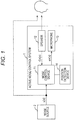
- Fig. 1 illustrates a configuration of an active noise control system according to an embodiment.
- an active noise control system 1 includes a noise control device 11, a speaker 12, a microphone 13, and a position detection device 14.
- the active noise control system 1 may be a system installed in an automobile, and may be a system that cancels noise generated from a noise source 2 at a cancel point, with the position of a head of a user who boards the automobile as the cancel point.
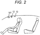
- the speaker 12 and the microphone 13 are arranged, for example, on a ceiling in front of a target seat (right front seat in Fig. 2 ) that is a seat on which a user who is a target of noise cancellation in an automobile is seated.
- the position detection device 14 is a device that detects the position of the head of the user, and includes a camera 141 that is provided in front of the target seat illustrated in Fig. 2 to photograph a periphery of the target seat or a sensor (not illustrated) that detects a position of the target seat in a front-back direction or an inclination of a backrest, and detects an image photographed by the camera 141 or the position of the head of the user from the position of the target seat or the inclination of the backrest that is detected by the sensor.
- a camera 141 that is provided in front of the target seat illustrated in Fig. 2 to photograph a periphery of the target seat or a sensor (not illustrated) that detects a position of the target seat in a front-back direction or an inclination of a backrest, and detects an image photographed by the camera 141 or the position of the head of the user from the position of the target seat or the inclination of the backrest that is detected by the sensor.
- the noise control device 11 of the active noise control system 1 uses a noise signal x (n) representing the noise generated from the noise source 2 and a microphone error signal err (n) which is a voice signal picked up by the microphone 13 to generate a cancel signal CA (n) that cancels the noise generated from the noise source 2 at the cancel point and outputs the generated cancel signal CA (n) from the speaker 12.
- FIG. 3 illustrates a configuration of the noise control device 11 of the active noise control system 1.
- the noise control device 11 includes a signal processing unit 111 and a switching control unit 112.
- the signal processing unit 111 includes a variable filter 1111, an adaptive algorithm execution unit 1112, an estimation filter 1113 for which a transfer function S ⁇ (z) is preset, a subtractor 1114, three auxiliary filters 1115 for which transfer functions H1 (z), H2 (z), and H3 (z) are each preset, and a selector 1116 that selects and outputs one of outputs of the three auxiliary filters 1115 according to the control of the switching control unit 112.
- the input noise signal x (n) is output to the speaker 12 as the cancel signal CA (n) through the variable filter 1111.
- the input noise signal x (n) is transmitted to the selector 1116 through each of the three auxiliary filters 1115, and the selector 1116 selects one of the outputs of the three auxiliary filters 1115 according to the control of the switching control unit 112 and transmits the selected output to the subtractor 1114.
- the subtractor 1114 subtracts and corrects the output of the selector 1116 from the microphone error signal err (n) picked up by the microphone 13, and outputs the corrected output to the adaptive algorithm execution unit 1112 as an error.
- variable filter 1111, the adaptive algorithm execution unit 1112, and the estimation filter 1113 configure a Filtered-X adaptive filter.
- An estimation transfer characteristic S ⁇ (z) estimated by actual measurement of the transfer function S (z) from the signal processing unit 111 to the microphone 13 is preset in the estimation filter 1113, and the estimation filter 1113 convoluted the transfer characteristic S ⁇ (z) with the input noise signal x (n) and outputs the convoluted transfer characteristic S ⁇ (z) to the adaptive algorithm execution unit 1112.
- the adaptive algorithm execution unit 1112 receives the noise signal x (n) with which the transfer function S ⁇ (z) is convoluted by the estimation filter 1113 and the error output from the subtractor 1114 as an input, and executes the adaptive algorithm by NLMS to update a transfer function W (z) of the variable filter 1111 so that the error becomes 0.
- first stage learning processing and second stage learning processing are performed on each of the transfer functions H1 (z), H2 (z), and H3 (z) of each auxiliary filter 1115 of the signal processing unit 111, and thus the transfer functions H1 (z), H2 (z), and H3 (z) are set.
- each of the transfer functions H1 (z), H2 (z), and H3 (z) of the three auxiliary filters 1115 corresponds to different cancel points.
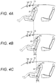
- the transfer function H1 (z) corresponds to a cancel point P1 that is a standard position of the head of a user when the position of the target seat is set to a position that is ahead of a standard position in the front-back direction by a distance D as illustrated in Fig. 4A
- the transfer function H2 (z) corresponds to a cancel point P2 that is the standard position of the head of the user when the position of the target seat is set to the standard position in the front-back direction as illustrated in Fig.
- the transfer function H2 (z) corresponds to a cancel point P3 that is the standard position of the head of the user when the position of the target seat is set to a position that is behind the standard position in the front-back direction by the distance D as illustrated in Fig. 4C .
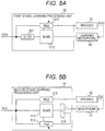
- the first stage learning processing is performed in a configuration in which the first signal processing unit is replaced with a first stage learning processing unit 50 illustrated in Fig. 5A and the microphone 13 is replaced with the learning microphone 41.
- the learning microphone 41 when learning a transfer function Hi (z), the learning microphone 41 is arranged at a cancel point Pi as illustrated in Figs. 4A, 4B, and 4C . That is, when learning the transfer function H1 (z), the learning microphone 41 is arranged at the cancel point P1 as illustrated in Fig. 4A , when learning the transfer function H2 (z), the learning microphone 41 is arranged at the cancel point P2 as illustrated in Fig. 4B , and when learning the transfer function H3 (z), the learning microphone 41 is arranged at the cancel point P3 as illustrated in Fig. 4C .
- the first stage learning processing unit 50 illustrated in Fig. 5A has a configuration in which the three auxiliary filters 1115, the selector 1116, and the subtractor 1114 are removed from the signal processing unit 111 illustrated in Fig. 3 , the estimation filter 1113 is replaced with the first stage learning estimation filter 501 for which the transfer function S v ⁇ (z) is set, and the output of the learning microphone 41 is input to the adaptive algorithm execution unit 1112 as an error.
- the transfer function S v ⁇ (z) represents the transfer function from the first stage learning processing unit 50 to the learning microphone 41.
- the transfer function W (z) of the variable filter 1111 is converged and stabilized by the adaptive operation by the adaptive algorithm execution unit 1112, and the converged and stabilized transfer function W (z) is obtained as the result of the first stage learning processing.
- the second stage learning processing is set in a configuration in which the signal processing unit 111 of Fig. 3 is replaced with the second stage learning processing unit 51 illustrated in Fig. 5B .
- the second stage learning processing unit 51 illustrated in Fig. 5B includes a second stage learning fixed filter 511 for which the transfer function W (z) obtained as a result of the first stage learning processing is set as the transfer function, a second stage learning variable filter 512, a second stage learning adaptive algorithm execution unit 513, and a second stage learning subtractor 514.
- the noise signal x (n) input to the second stage learning processing unit 51 is output to the speaker 12 through the second stage learning fixed filter 511.
- the input noise signal x (n) is transmitted to the second stage learning subtractor 514 through the second stage learning variable filter 512, and the second stage learning subtractor 514 subtracts the output of the second stage learning variable filter 512 from the signal picked up by the microphone 13 and outputs the subtracted output to the second stage learning adaptive algorithm execution unit 513 as an error.
- the transfer function H (z) of the second stage learning variable filter 512 is converged and stabilized by the adaptive operation by the second stage learning adaptive algorithm execution unit 513, and the converged and stabilized transfer function H (z) is learned as a transfer function Hi (z) of an i-th auxiliary filter 1115.
- the switching control unit 112 switches the auxiliary filter 1115 that selects the output by the selector 1116 and transmits the selected output to the subtractor 1114 according to the position of the head of the user of the target seat detected by the position detection device 14.
- This switching is performed by calculating a cancel point closest to the position of the head detected by the position detection device 14 among the cancel points P1, P2, and P3 of Figs. 4A, 4B, and 4C , and causing the selector 1116 to switch the output transmitted to the subtractor 1114 to the output of the auxiliary filter 1115 for which a transfer function Hx (z) corresponding to the calculated cancel point Px is set when the calculated cancel point changes.
- the selector 1116 switches the output transmitted to the subtractor 1114 to the output of the auxiliary filter 1115 for which the transfer function H1 (z) is set
- the selector 1116 switches the output transmitted to the subtractor 1114 to the output of the auxiliary filter 1115 for which the transfer function H2 (z) is set
- the selector 1116 switches the output transmitted to the subtractor 1114 to the output of the auxiliary filter 1115 for which the transfer function H3 (z) is set.
- this switching is performed so that the output transmitted from the selector 1116 to the subtractor 1114 stepwise changes from the output before the switching to the output after the switching.
- the ratio R_H1 decreases from 100% to 0% by 10% and the ratio R_H2 increases from 0% to 100% by 10% at predetermined time intervals.
- the ratio of the output of the auxiliary filter 1115 input to the subtractor 1114 is set by controlling a selection frequency of the output of the auxiliary filter 1115 before and after the switching of the selector 1116.
- the selector 1116 repeats selecting the output value of the auxiliary filter 1115, for which transfer function H2 (z) is set, twice after selecting the output value of the auxiliary filter 1115, for which function H1 (z) is set, eight times.
- the selector 1116 alternately performs selecting the output value of the auxiliary filter 1115 for which the transfer function H1 (z) is set and selecting the output value of the auxiliary filter 1115 for which function H2 (z) is set.
- the transition time length where the above-mentioned stepwise switching is performed may be set so that the larger the distance between cancel points Pj and Pk corresponding to transfer functions Hj (z) and Hk (z) set in the auxiliary filter 1115 before and after the switching, the longer the transition time it takes. That is, for example, since the distance between the cancel points P1 and P3 is larger than the distance between the cancel points P1 and P2 or the distance between the cancel points P2 and P3 in Figs.
- the transition time length at the time of switching between the output of the auxiliary filter 1115 for which the transfer function H1 (z) is set and the output of the auxiliary filter 1115 for which the transfer function H3 (z) is set may be larger than the transition time length at the time of switching between the outputs of the auxiliary filter 1115 for which other transfer functions are set.
- the number of steps of changing the ratio of the output before and after the switching of the output transmitted from the selector 1116 to the subtractor 1114 may be arbitrary, and for example, as illustrated in Fig. 6B , for the case of switching from the output of the auxiliary filter 1115 for which the transfer function H1 (z) is set to the output of the auxiliary filter 1115 for which the transfer function H2 (z) is set, the ratio R_H1 of the output of the auxiliary filter 1115 for which the transfer function H1 (z) input to the subtractor 1114 is set may decrease to 100%, 50%, and 0% during T (H1 - H2) and the ratio R_H2 of the auxiliary filter 1115 for which the transfer function H2 (z) input to the subtractor 1114 is set may increase to 0%, 50%, and 100%.
- the auxiliary filter 1115 used to generate the error signal input to the adaptive filter is switched to the auxiliary filter 1115 that can satisfactorily cancel the noise at the cancel point close to the position of the head of the user, and therefore it is possible to satisfactorily cancel the noise heard by the user regardless of the displacement of the head of the user.
- the switching can suppress the divergence of the adaptive filter or the occurrence of the noise of the noise cancellation sound.
- the cancel point P2 corresponding to the transfer function H2 (z) exists between the cancel point P1 corresponding to the transfer function H1 (z) and the cancel point P3 corresponding to the transfer function H3 (z), and since transfer function H2 (z) can be expected to be an intermediate value between transfer function H1 (z) and transfer function H3 (z), in the above embodiment, the switching between the output of the auxiliary filter 1115 for which transfer function H1 (z) is set and the output of the auxiliary filter 1115 for which the transfer function H3 (z) is set may be performed via the transfer function H2 (z).
- the outputs of the two auxiliary filters 1115 corresponding to the two cancel points adjacent to the position of the head detected by the position detection device 14 are output to the subtractor 1114 at a ratio of reciprocal of the distance between the corresponding cancel point and the position of the head detected by the position detection device 14, so the virtual auxiliary filter 1115 simulating the transfer function obtained when the learning microphone 41 is arranged at the position of the head detected by the position detection device 14 to perform the learning by using the two auxiliary filters 1115 and the selector 1116 may be configured.
- the noise heard by the user can be satisfactorily canceled using the two auxiliary filters 1115 in which the position between the corresponding cancel points is the position of the head.
- the speaker 12, the microphone 13, the camera 141 of the position detection device 14, and the sensor may be provided for each seat of the automobile to cancel noise for users at each seat.
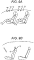
- the speaker 12 and the microphone 13 are provided on the ceiling in front of the target seat, but the positions of the speaker 12 and the microphone 13 may be different. That is, for example, as illustrated in Fig. 9B , the speaker 12 and the microphone 13 may be fixedly provided on the target seat.
- the noise signal x (n) input to the active noise control system 1 may be an audio signal output from a noise source, a voice signal in which the noise of the noise source is picked up by the noise microphone separately provided, or a signal simulating the noise of the noise source generated by a simulated sound generation device separately provided.
- an engine sound picked up by a separate noise microphone may be a noise signal x (n), or a simulated sound simulating an engine sound generated by a simulated sound generation device separately provided may be the noise signal x (n).
- above embodiments may be expanded so that positions corresponding to left and right ears of the target seat are two cancel points and the noise at each cancel point is canceled.
- a set of a left speaker 61 and a left microphone 62 for mainly canceling noise in the left ear, and a set of a right speaker 63 and a right microphone 64 for mainly canceling noise in the right ear are provided.
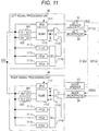
- the noise control device 11 is provided with a left signal processing unit 65 and a right signal processing unit 66 illustrated in Fig. 11 , instead of the signal processing unit 111.
- the configuration of the left signal processing unit 65 is substantially the same as the configuration of the signal processing unit 111 illustrated in Fig. 3 , but the left signal processing unit 65 is connected to the left speaker 61 instead of the speaker 12, and is connected to the left microphone 62 instead of the microphone 13.
- a left first estimation filter 651 for which an estimation transfer characteristic S 11 ⁇ (z) of a transfer function S 11 (z) from the left signal processing unit 65 that uses the noise signal x (n) as an input and transmits an output to the adaptive algorithm execution unit 1112 to the left microphone 62 is set
- a left second estimation filter 652 for which an estimation transfer characteristic S 21 ⁇ (z) of a transfer function S 21 (z) from the left signal processing unit 65 to the right microphone 64 is set.
- an error e1 output from the subtractor 1114 and an error e2 output from the subtractor 1114 of the right signal processing unit 66 are input to the adaptive algorithm execution unit 1112, and in the adaptive algorithm execution unit 1112, a transfer function W (z) of the variable filter 1111 is updated so that the error e1 and the error e2 become 0.
- the configuration of the right signal processing unit 66 is substantially the same as the configuration of the signal processing unit 111 illustrated in Fig. 3 , but the left signal processing unit 65 is connected to the right speaker 63 instead of the speaker 12, and is connected to the right microphone 64 instead of the microphone 13.
- a right first estimation filter 661 for which an estimation transfer characteristic S 22 ⁇ (z) of a transfer function S 22 (z) from the right signal processing unit 66 that uses the noise signal x (n) as an input and transmits an output to the adaptive algorithm execution unit 1112 to the right microphone 64 is set
- a right second estimation filter 662 for which an estimation transfer characteristic S 12 ⁇ (z) of a transfer function S 12 (z) from the right signal processing unit 66 to the left microphone 62 is set.
- the error e2 output from the subtractor 1114 and the error e1 output from the subtractor 1114 of the right signal processing unit 66 are input to the adaptive algorithm execution unit 1112, and in the adaptive algorithm execution unit 1112, the transfer function W (z) of the variable filter 1111 is updated so that the error e1 and the error e2 become 0.
- the selectors 1116 of the left signal processing unit 65 and the right signal processing unit 66 select the output and switch the auxiliary filters 1115 that transmit the selected output to the subtractor 1114.
- each auxiliary filter 1115 of the left signal processing unit 65 and the right signal processing unit 66 are set by performing the first stage learning processing and the second stage learning processing in advance in the same manner as each auxiliary filter 1115 of the signal processing unit 111 illustrated in Fig. 3 .
- the first stage learning processing is performed using the left learning microphone and the right learning microphone instead of the learning microphone 41.
- the left learning microphone is arranged at the standard position of the left ear of the user and the right learning microphone is arranged at the standard position of the right ear when the position of the target seat is set to be a position ahead of the standard position in the front-back direction by the distance D as illustrated in Fig. 4A
- learning the transfer function H2 (z) the left learning microphone is arranged at a standard position of the left ear of the user and the right learning microphone is arranged at the standard position of the right ear when the position of the target seat is set to be the standard position in the front-back direction as illustrated in Fig.
- the left learning microphone is arranged at the standard position of the left ear of the user and the right learning microphone is arranged at the standard position of the right ear when the position of the target seat is set to be a position behind the standard position in the front-back direction by the distance D as illustrated in Fig. 4C .
- the transfer functions of the variable filters 1111 of the left signal processing unit 65 and the right signal processing unit 66 where the noise represented by the outputs of the left learning microphone and the right learning microphone 13 is eliminated are learned
- the transfer functions of the variable filters 1111 of the left signal processing unit 65 and the right signal processing unit 66 are fixed to the transfer function in the first stage learning processing, and the transfer function of the learning auxiliary filter where the error e1 output from the subtractor 1114 of the left signal processing unit 65 and the error e2 output from the subtractor 1114 of the right signal processing unit 66 become 0 which are obtained in the state in which each auxiliary filter 1115 and selector 1116 are replaced with the learning auxiliary filter is obtained, which is the transfer function Hi (z).
- the above embodiments illustrate the case where there is only one noise source 2
- the above embodiments extend the configuration of the noise control device 11 to consider the propagation of each noise source 2 to each cancel point, and as a result, can be applied even when there are a plurality of noise sources 2.
- the number of auxiliary filters 1115 may be three, but the number of auxiliary filters 1115 may be two or more.
Landscapes
- Physics & Mathematics (AREA)
- Engineering & Computer Science (AREA)
- Acoustics & Sound (AREA)
- Multimedia (AREA)
- Soundproofing, Sound Blocking, And Sound Damping (AREA)
- Fittings On The Vehicle Exterior For Carrying Loads, And Devices For Holding Or Mounting Articles (AREA)
Abstract
Description
- The present invention relates to a technology of active noise control (ANC) that reduces noise by radiating noise cancellation sound from which noise is canceled.
- As a technology of active noise control that reduces noise by radiating noise cancellation sound from which noise is canceled, a technology is known in which a microphone and a speaker that are arranged near a noise cancel position and an adaptive filter that generates the noise cancellation sound output from the speaker in an output signal of a noise source or a signal simulating the output signal are provided, and the adaptive filter adaptively sets a transfer function using, as an error signal, a signal obtained by correcting an output of a microphone using an auxiliary filter.
- Here, in this technology, a transfer function learned in advance which corrects a difference between a transfer function from a noise source to a noise cancel position and a transfer function from the noise source to the microphone and a difference between a transfer function from the speaker to the noise cancel position and a transfer function from the speaker to the microphone is preset in the auxiliary filter, and the auxiliary filter is used to cancel noise at the noise cancel position different from a position of the microphone.
- In addition, a technology is known in which a set of the microphone, the speaker, the adaptive filter, and the auxiliary filter corresponding to each of the two noise cancel positions is provided, and outputs the noise cancellation sound from which noise is canceled at the corresponding noise cancel position in each set by using the above-described technology to cancel the noise generated from the noise source at two noise cancel positions, respectively (for example,
JP 2018-72770 A - In the case of canceling noise heard by a user by using the technology for canceling the noise at the noise cancel position different from the position of the microphone using the above-mentioned auxiliary filter, if a head of a user shifts from the noise cancel position along with the displacement of the user, the noise heard by the user may not be canceled satisfactorily.
- Therefore, the transfer function of the auxiliary filter is learned for a plurality of different noise cancel positions, and the transf0r function of the auxiliary filter is switched to the learned transfer function for the noise cancel position corresponding to the position of the head of the user along with the displacement of the head of the user, and as a result, it is conceivable to cancel the noise heard by the user regardless of the displacement of the head of the user.
- However, in this case, when the transfer function of the auxiliary filter is switched, problems such as divergence of the adaptive filter and generation of noise in the noise cancellation sound may occur.
- Therefore, an object of the present invention is to provide an active noise control system that is capable to switch characteristics without hindrance according to a displacement of a target whose noise needs to be canceled so as to cancel the noise at the position after the displacement.
The invention relates to an active noise control system and an automobile comprising such systems according to the appended claims. Embodiments are disclosed in the dependent claims. - An aspect of the present invention provides an active noise control system for reducing noise heard by an object, the active noise control system, including: a microphone; an adaptive filter that uses a noise signal representing the noise as an input; a speaker that outputs an output of the adaptive filter as a noise cancellation sound; a plurality of auxiliary filters that use the noise signal as an input and are provided corresponding to a plurality of different positions; an error correction unit that corrects a microphone output signal, which is the output of the microphone, using the output of one of the auxiliary filters and outputs the corrected microphone output signal to the adaptive filter as an error signal; a position detection unit that detects a position of the object; and a switching control unit that performs a switching operation of switching a signal output as the error signal from the error correction unit to a signal obtained by correcting the microphone output signal using the output of the auxiliary filter after the switching by controlling the error correction unit using the auxiliary filter, in which the corresponding position matches the position of the object, as the auxiliary filter after the switching, when the auxiliary filter in which the corresponding position matches the position of the object detected by the position detection unit changes.
- The adaptive filter executes a predetermined adaptive algorithm using an error indicated by an error signal input from the error correction unit and updates a transfer function of the adaptive filter. The transfer function learned as the transfer function in which the error indicated by the error signal becomes 0 is preset in the plurality of auxiliary filters when the noise is canceled by the noise cancellation sound at the corresponding position.
According to embodiments, the switching control unit may gradually or stepwise decrease a ratio at which the signal obtained by correcting the microphone output signal using the output of the auxiliary filter before the switching at the switching operation is output as the error signal by using, as the auxiliary filter before the switching, the auxiliary filter using the output for the correction of the microphone output signal before the switching operation to 0%, and gradually or stepwise increase a ratio at which the signal obtained by correcting the microphone output signal by using the output of the auxiliary filter after the switching is output as the error signal, or the decrement to 100%. - According to such an active noise control system, the auxiliary filter used to generate the error signal to input to the adaptive filter according to the change in the position of the object is switched to the auxiliary filter after the switching that is the auxiliary filter capable of satisfactorily canceling the noise at the position matching the position of the object, and as a result, it is possible to satisfactorily cancel the noise heard by the object regardless of the displacement of the object.
- In addition, since the ratio at which the signal generated using the auxiliary filter after the switching is output as the error signal gradually or stepwise increases while the ratio at which the signal generated using the auxiliary filter before the switching is output as the error signal gradually or stepwise decreases, the switching can suppress the divergence of the adaptive filter or the occurrence of the noise of the noise cancellation sound.
- In addition, an aspect of the present invention provides an active noise control system for reducing noise heard by an object, the active noise control system, including: a microphone; an adaptive filter that uses a noise signal representing the noise as an input; a speaker that outputs an output of the adaptive filter as a noise cancellation sound; a plurality of auxiliary filters that use the noise signal as an input and are provided corresponding to a plurality of different positions; an error correction unit that corrects a microphone output signal, which is the output of the microphone, using an output of one of the auxiliary filters and outputs the corrected microphone output signal to the adaptive filter as an error signal; a position detection unit that detects a position of the object; and a switching control unit that controls the error correction unit to output a signal obtained by correcting the microphone output signal using an output of a first mixture target auxiliary filter and a signal obtained by correcting the microphone output signal using an output of a second mixture target auxiliary filter as the error signal from the error correction unit at a ratio after switching which is a ratio determined according to a ratio of a distance between a position corresponding to the first mixture target auxiliary filter and a position of the object and a distance between a position corresponding to the second mixture target auxiliary filter and the position of the object, using, as the first mixture target auxiliary filter and the second mixture target auxiliary filter, two auxiliary filters in which two positions corresponding to the two auxiliary filters become the position of the object when the position of the object detected by the position detection unit changes. The adaptive filter executes a predetermined adaptive algorithm using an error indicated by an error signal input from the error correction unit and updates a transfer function of the adaptive filter. The transfer function learned as the transfer function in which the error indicated by the error signal becomes 0 is preset in the plurality of auxiliary filters when the noise is canceled by the noise cancellation sound at the corresponding position.
- According to such an active noise control system, even if the position of the object is the position where an auxiliary filter capable of satisfactorily canceling the noise at the position is not prepared, it is possible to cancel the noise heard by the object by using the two auxiliary filters in which the position between the positions where the noise can be canceled satisfactorily is the position of the object.
- Here, the active noise control system may be configured so that the switching control unit gradually or stepwise changes the ratio of the signal obtained by correcting the microphone output signal, which is output from the error correction unit as the error signal, using the output of the first mixture target auxiliary filter and the signal obtained by correcting the microphone output signal using the output of the second mixture target auxiliary filter to the ratio after the switching, in the switching operation.
- Here, in the active noise control system, the object may be the head of the user who is seated on the seat that is displaceable within the predetermined range, and each position where the head of the human body seated on the seats at the positions is normally positioned may be the positions corresponding to each of the plurality of auxiliary filters, each position of the plurality of different seats within the displacement range being obtained.
- Further, an aspect of the present invention also provides an active noise control system that includes two systems of a first system and a second system including a microphone, an adaptive filter, a speaker, a plurality of auxiliary filters, and an error correction unit. The plurality of auxiliary filters of the first system and the plurality of auxiliary filters of the second system are associated in a one-to-one correspondence, and a position relationship between a position corresponding to the auxiliary filter of the first system and a position corresponding the auxiliary filter of the second system that are associated matches or approximates a position relationship of predetermined two positions fixed to the object. In addition, the adaptive filter of the first system and the adaptive filter of the second system execute a predetermined adaptive algorithm using an error signal output from the error correction unit of the first system and an error signal output from the error correction unit of the second system to update a transfer function of the adaptive filter. The learned transfer function as the transfer function in which the error signal output from the error correction unit of the first system and the error signal output from the error correction unit of the second system become 0 is preset in the plurality of auxiliary filters of the first system and the plurality of auxiliary filters of the second system when the noise is canceled by noise cancellation sounds output from the speaker of the first system and the speaker of the second system at the position corresponding to the auxiliary filter of the first system and the position corresponding to the auxiliary filter of the second system.
- Here, in the active noise control system, the object may be the head of the user who is seated on the displaceable seat within the predetermined range, and each position where a left ear of the human body seated on the seat at the position may be normally positioned is positions corresponding to each of the plurality of auxiliary filters of the first system and each position where a right ear of the human body seated on the seat at the position may be positions corresponding to each of the plurality of auxiliary filters of the second system, each position of the plurality of different seats within the displacement range being obtained, and the plurality of auxiliary filters of the first system and the plurality of auxiliary filters of the second system that are associated may be the plurality of auxiliary filters of the first system and the plurality of auxiliary filters of the second system in which the position corresponding to the position of the same seat is obtained.
- In addition, in the above active noise control system, the predetermined seat may be a seat of an automobile.
- As described above, the present invention provides an active noise control system that is capable to switch the characteristics without hindrance according to the displacement of the target whose noise needs to be canceled so as to cancel the noise at the position after the displacement.
-
Fig. 1 is a block diagram illustrating a configuration of an active noise control system according to an embodiment of the present invention. -
Fig. 2 is a diagram illustrating an arrangement of a speaker and a microphone of the active noise control system according to an embodiment of the present invention. -
Fig. 3 is a block diagram illustrating a configuration of a noise control device according to an embodiment of the present invention. -
Figs. 4A to 4C are diagrams illustrating arrangement examples of a learning microphone according to an embodiment of the present invention. -
Figs. 5A and 5B are block diagrams illustrating a configuration of learning of a transfer function of an auxiliary filter according to an embodiment of the present invention. -
Figs. 6A and 6B are diagrams illustrating a switching operation of the auxiliary filter according to an embodiment of the present invention. -
Figs. 7A and 7B are diagrams illustrating the switching operation of the auxiliary filter according to an embodiment of the present invention. -
Figs. 8A ,8B1, and 8B2 are diagrams illustrating the switching operation of the auxiliary filter according to an embodiment of the present invention. -
Figs. 9A and 9B are diagrams illustrating another configuration example of the active noise control system according to an embodiment of the present invention. -
Figs. 10A and 10B are diagrams illustrating another configuration example of the active noise control system according to an embodiment of the present invention. -
Fig. 11 is a block diagram illustrating another configuration example of the noise control device according to an embodiment of the present invention. - Hereinafter, embodiments of the present invention will be described.
-
Fig. 1 illustrates a configuration of an active noise control system according to an embodiment. - As illustrated, an active
noise control system 1 includes anoise control device 11, aspeaker 12, amicrophone 13, and aposition detection device 14. - The active
noise control system 1 may be a system installed in an automobile, and may be a system that cancels noise generated from anoise source 2 at a cancel point, with the position of a head of a user who boards the automobile as the cancel point. - Further, as illustrated in
Fig. 2 , thespeaker 12 and themicrophone 13 are arranged, for example, on a ceiling in front of a target seat (right front seat inFig. 2 ) that is a seat on which a user who is a target of noise cancellation in an automobile is seated. - In addition, the
position detection device 14 is a device that detects the position of the head of the user, and includes acamera 141 that is provided in front of the target seat illustrated inFig. 2 to photograph a periphery of the target seat or a sensor (not illustrated) that detects a position of the target seat in a front-back direction or an inclination of a backrest, and detects an image photographed by thecamera 141 or the position of the head of the user from the position of the target seat or the inclination of the backrest that is detected by the sensor. - Returning to
Fig. 1 , thenoise control device 11 of the activenoise control system 1 uses a noise signal x (n) representing the noise generated from thenoise source 2 and a microphone error signal err (n) which is a voice signal picked up by themicrophone 13 to generate a cancel signal CA (n) that cancels the noise generated from thenoise source 2 at the cancel point and outputs the generated cancel signal CA (n) from thespeaker 12. - Subsequently,
Fig. 3 illustrates a configuration of thenoise control device 11 of the activenoise control system 1. - As illustrated, the
noise control device 11 includes asignal processing unit 111 and aswitching control unit 112. - The
signal processing unit 111 includes avariable filter 1111, an adaptivealgorithm execution unit 1112, anestimation filter 1113 for which a transfer function S^ (z) is preset, asubtractor 1114, threeauxiliary filters 1115 for which transfer functions H1 (z), H2 (z), and H3 (z) are each preset, and aselector 1116 that selects and outputs one of outputs of the threeauxiliary filters 1115 according to the control of theswitching control unit 112. - In such a configuration of the
signal processing unit 111, the input noise signal x (n) is output to thespeaker 12 as the cancel signal CA (n) through thevariable filter 1111. - In addition, the input noise signal x (n) is transmitted to the
selector 1116 through each of the threeauxiliary filters 1115, and theselector 1116 selects one of the outputs of the threeauxiliary filters 1115 according to the control of theswitching control unit 112 and transmits the selected output to thesubtractor 1114. Thesubtractor 1114 subtracts and corrects the output of theselector 1116 from the microphone error signal err (n) picked up by themicrophone 13, and outputs the corrected output to the adaptivealgorithm execution unit 1112 as an error. - Subsequently, the
variable filter 1111, the adaptivealgorithm execution unit 1112, and theestimation filter 1113 configure a Filtered-X adaptive filter. An estimation transfer characteristic S^ (z) estimated by actual measurement of the transfer function S (z) from thesignal processing unit 111 to themicrophone 13 is preset in theestimation filter 1113, and theestimation filter 1113 convoluted the transfer characteristic S^ (z) with the input noise signal x (n) and outputs the convoluted transfer characteristic S^ (z) to the adaptivealgorithm execution unit 1112. - Then, the adaptive
algorithm execution unit 1112 receives the noise signal x (n) with which the transfer function S^ (z) is convoluted by theestimation filter 1113 and the error output from thesubtractor 1114 as an input, and executes the adaptive algorithm by NLMS to update a transfer function W (z) of thevariable filter 1111 so that the error becomes 0. - Subsequently, first stage learning processing and second stage learning processing are performed on each of the transfer functions H1 (z), H2 (z), and H3 (z) of each
auxiliary filter 1115 of thesignal processing unit 111, and thus the transfer functions H1 (z), H2 (z), and H3 (z) are set. - Here, each of the transfer functions H1 (z), H2 (z), and H3 (z) of the three
auxiliary filters 1115 corresponds to different cancel points. - That is, the transfer function H1 (z) corresponds to a cancel point P1 that is a standard position of the head of a user when the position of the target seat is set to a position that is ahead of a standard position in the front-back direction by a distance D as illustrated in
Fig. 4A , the transfer function H2 (z) corresponds to a cancel point P2 that is the standard position of the head of the user when the position of the target seat is set to the standard position in the front-back direction as illustrated inFig. 4B , and the transfer function H2 (z) corresponds to a cancel point P3 that is the standard position of the head of the user when the position of the target seat is set to a position that is behind the standard position in the front-back direction by the distance D as illustrated inFig. 4C . - The first stage learning processing is performed in a configuration in which the first signal processing unit is replaced with a first stage
learning processing unit 50 illustrated inFig. 5A and themicrophone 13 is replaced with the learningmicrophone 41. - Assuming i is an arbitrary number among 1, 2, and 3, when learning a transfer function Hi (z), the learning
microphone 41 is arranged at a cancel point Pi as illustrated inFigs. 4A, 4B, and 4C . That is, when learning the transfer function H1 (z), the learningmicrophone 41 is arranged at the cancel point P1 as illustrated inFig. 4A , when learning the transfer function H2 (z), the learningmicrophone 41 is arranged at the cancel point P2 as illustrated inFig. 4B , and when learning the transfer function H3 (z), the learningmicrophone 41 is arranged at the cancel point P3 as illustrated inFig. 4C . - The first stage
learning processing unit 50 illustrated inFig. 5A has a configuration in which the threeauxiliary filters 1115, theselector 1116, and thesubtractor 1114 are removed from thesignal processing unit 111 illustrated inFig. 3 , theestimation filter 1113 is replaced with the first stage learningestimation filter 501 for which the transfer function Sv^ (z) is set, and the output of the learningmicrophone 41 is input to the adaptivealgorithm execution unit 1112 as an error. However, the transfer function Sv^ (z) represents the transfer function from the first stagelearning processing unit 50 to the learningmicrophone 41. - Then, in such a configuration, the transfer function W (z) of the
variable filter 1111 is converged and stabilized by the adaptive operation by the adaptivealgorithm execution unit 1112, and the converged and stabilized transfer function W (z) is obtained as the result of the first stage learning processing. - Subsequently, the second stage learning processing is set in a configuration in which the
signal processing unit 111 ofFig. 3 is replaced with the second stage learningprocessing unit 51 illustrated inFig. 5B . - The second stage learning
processing unit 51 illustrated inFig. 5B includes a second stage learning fixedfilter 511 for which the transfer function W (z) obtained as a result of the first stage learning processing is set as the transfer function, a second stage learningvariable filter 512, a second stage learning adaptivealgorithm execution unit 513, and a secondstage learning subtractor 514. - The noise signal x (n) input to the second stage learning
processing unit 51 is output to thespeaker 12 through the second stage learning fixedfilter 511. - Further, the input noise signal x (n) is transmitted to the second
stage learning subtractor 514 through the second stage learningvariable filter 512, and the secondstage learning subtractor 514 subtracts the output of the second stage learningvariable filter 512 from the signal picked up by themicrophone 13 and outputs the subtracted output to the second stage learning adaptivealgorithm execution unit 513 as an error. - Then, in such a configuration, the transfer function H (z) of the second stage learning
variable filter 512 is converged and stabilized by the adaptive operation by the second stage learning adaptivealgorithm execution unit 513, and the converged and stabilized transfer function H (z) is learned as a transfer function Hi (z) of an i-thauxiliary filter 1115. - Subsequently the switching operation performed by the switching
control unit 112 of thenoise control device 11 ofFig. 3 will be described. - The switching
control unit 112 switches theauxiliary filter 1115 that selects the output by theselector 1116 and transmits the selected output to thesubtractor 1114 according to the position of the head of the user of the target seat detected by theposition detection device 14. - This switching is performed by calculating a cancel point closest to the position of the head detected by the
position detection device 14 among the cancel points P1, P2, and P3 ofFigs. 4A, 4B, and 4C , and causing theselector 1116 to switch the output transmitted to thesubtractor 1114 to the output of theauxiliary filter 1115 for which a transfer function Hx (z) corresponding to the calculated cancel point Px is set when the calculated cancel point changes. - That is, among the cancel points P1, P2, and P3 of
Figs. 4A, 4B, and 4C , when the cancel point P1 is closest to the position of the head detected by theposition detection device 14, theselector 1116 switches the output transmitted to thesubtractor 1114 to the output of theauxiliary filter 1115 for which the transfer function H1 (z) is set, when the cancel point P2 is closest to the position of the head detected by theposition detection device 14, theselector 1116 switches the output transmitted to thesubtractor 1114 to the output of theauxiliary filter 1115 for which the transfer function H2 (z) is set, and when the cancel point P3 is closest to the position of the head detected by theposition detection device 14, theselector 1116 switches the output transmitted to thesubtractor 1114 to the output of theauxiliary filter 1115 for which the transfer function H3 (z) is set. - In addition, this switching is performed so that the output transmitted from the
selector 1116 to thesubtractor 1114 stepwise changes from the output before the switching to the output after the switching. - That is, for example, when the output before the switching transmitted from the
selector 1116 to thesubtractor 1114 is the output of theauxiliary filter 1115 for which the transfer function H1 (z) is set, and the output after the switching is the output of theauxiliary filter 1115 for which the transfer function H2 (z) is set, as illustrated inFig. 6A , a ratio R_H1 of the output ofauxiliary filter 1115 for which the transfer function H1 (z) input to thesubtractor 1114 is set stepwise decreases from 100% to 0% during a transition time length T (H1 - H2) from the preset transfer function H1 (z) to the transfer function H2 (z), a ratio R_H2 of the output of theauxiliary filter 1115 for which the transfer function H2 (z) input to thesubtractor 1114 stepwise increases from 0% to 100% while satisfying R_H1 + R_H2 = 100%, and the ratio R_H2 needs to be maintained at 100% after the lapse of T (H1 - H2). InFig. 6A , the ratio R_H1 decreases from 100% to 0% by 10% and the ratio R_H2 increases from 0% to 100% by 10% at predetermined time intervals. - Here, the ratio of the output of the
auxiliary filter 1115 input to thesubtractor 1114 is set by controlling a selection frequency of the output of theauxiliary filter 1115 before and after the switching of theselector 1116. - That is, for example, when the output of the
auxiliary filter 1115 for which the transfer function H1 (z) is set is 80% and the output of theauxiliary filter 1115 for which the transfer function H2 (z) is set is 20%, theselector 1116 repeats selecting the output value of theauxiliary filter 1115, for which transfer function H2 (z) is set, twice after selecting the output value of theauxiliary filter 1115, for which function H1 (z) is set, eight times. Similarly, when the output of theauxiliary filter 1115 for which transfer function H1 (z) is set is 50% and the output of theauxiliary filter 1115 for which transfer function H2 (z) is set is 50%, theselector 1116 alternately performs selecting the output value of theauxiliary filter 1115 for which the transfer function H1 (z) is set and selecting the output value of theauxiliary filter 1115 for which function H2 (z) is set. - In addition, the transition time length where the above-mentioned stepwise switching is performed may be set so that the larger the distance between cancel points Pj and Pk corresponding to transfer functions Hj (z) and Hk (z) set in the
auxiliary filter 1115 before and after the switching, the longer the transition time it takes. That is, for example, since the distance between the cancel points P1 and P3 is larger than the distance between the cancel points P1 and P2 or the distance between the cancel points P2 and P3 inFigs. 4A to 4C , the transition time length at the time of switching between the output of theauxiliary filter 1115 for which the transfer function H1 (z) is set and the output of theauxiliary filter 1115 for which the transfer function H3 (z) is set may be larger than the transition time length at the time of switching between the outputs of theauxiliary filter 1115 for which other transfer functions are set. - In addition, the number of steps of changing the ratio of the output before and after the switching of the output transmitted from the
selector 1116 to thesubtractor 1114 may be arbitrary, and for example, as illustrated inFig. 6B , for the case of switching from the output of theauxiliary filter 1115 for which the transfer function H1 (z) is set to the output of theauxiliary filter 1115 for which the transfer function H2 (z) is set, the ratio R_H1 of the output of theauxiliary filter 1115 for which the transfer function H1 (z) input to thesubtractor 1114 is set may decrease to 100%, 50%, and 0% during T (H1 - H2) and the ratio R_H2 of theauxiliary filter 1115 for which the transfer function H2 (z) input to thesubtractor 1114 is set may increase to 0%, 50%, and 100%. - Embodiments of the present invention have been described above. According to embodiments as described above, the
auxiliary filter 1115 used to generate the error signal input to the adaptive filter is switched to theauxiliary filter 1115 that can satisfactorily cancel the noise at the cancel point close to the position of the head of the user, and therefore it is possible to satisfactorily cancel the noise heard by the user regardless of the displacement of the head of the user. - In addition, since the ratio at which the signal generated using the
auxiliary filter 1115 after the switching is output as the error signal gradually or stepwise increases while the ratio at which the signal generated using theauxiliary filter 1115 before the switching is output as the error signal gradually or stepwise decreases, the switching can suppress the divergence of the adaptive filter or the occurrence of the noise of the noise cancellation sound. - However, in above embodiments, the cancel point P2 corresponding to the transfer function H2 (z) exists between the cancel point P1 corresponding to the transfer function H1 (z) and the cancel point P3 corresponding to the transfer function H3 (z), and since transfer function H2 (z) can be expected to be an intermediate value between transfer function H1 (z) and transfer function H3 (z), in the above embodiment, the switching between the output of the
auxiliary filter 1115 for which transfer function H1 (z) is set and the output of theauxiliary filter 1115 for which the transfer function H3 (z) is set may be performed via the transfer function H2 (z). - That is, for example, in the case of switching from the output of the
auxiliary filter 1115 for which the transfer function H1 (z) is set to the output of theauxiliary filter 1115 for which the transfer function H3 (z) is set, as illustrated inFig. 7A or 7B , during the transition time length T (H1 - H3) from the preset transfer function H1 (z) to the transfer function H3 (z), the ratio R_H1 of the output of theauxiliary filter 1115 for which the transfer function H1 (z) input to thesubtractor 1114 is set stepwise decreases from 100% to 0%, and the ratio R_H2 of the output of theauxiliary filter 1115 for which the transfer function H2 (z) input to thesubtractor 1114 is set stepwise increases from 0% to 100% while satisfying R_H1 + R_H2 = 100%, and then the ratio R_H2 of the output of theauxiliary filter 1115 for which the transfer function H2 (z) input to thesubtractor 1114 is set stepwise decreases from 100% to 0% and the ratio R_H3 of the output of theauxiliary filter 1115 for which the transfer function H3 (z) input to thesubtractor 1114 is set stepwise increases from 0% to 100% while satisfying R_H2 + R_H3 = 100%, and after the lapse of T (H1 - H3), theselector 1116 may perform the switching of the output so that the R_H3 is maintained at 100%. - In addition, in above embodiments, when the position of the head detected by the
position detection device 14 is between the cancel points P1 and P2 ofFigs. 4A, 4B and 4C , or between the cancel points P2 and P3, in theselector 1116, the outputs of the twoauxiliary filters 1115 corresponding to the two cancel points adjacent to the position of the head detected by theposition detection device 14 are output to thesubtractor 1114 at a ratio of reciprocal of the distance between the corresponding cancel point and the position of the head detected by theposition detection device 14, so the virtualauxiliary filter 1115 simulating the transfer function obtained when the learningmicrophone 41 is arranged at the position of the head detected by theposition detection device 14 to perform the learning by using the twoauxiliary filters 1115 and theselector 1116 may be configured. - That is, for example, as illustrated in
Fig. 8A , when a position Pr of the head detected by theposition detection device 14 is between the cancel points P1 and P2 and a ratio of a distance from the position Pr to the cancel point P1 and a distance from the position Pr to the cancel point P2 is 70 : 30, the state in which the ratio of the output of theauxiliary filter 1115 for which the transfer function H1 (z) corresponding to the cancel point P1 input to thesubtractor 1114 and the output of theauxiliary filter 1115 for which the transfer function H2 (z) corresponding to the cancel point P2 input to thesubtractor 1114 is set 30 : 70 that is a ratio of reciprocal of a distance ratio 70 : 30 becomes the switched state. Then, in the case where the position of the head detected by theposition detection device 14 changes from the position of the cancel point P1 to the position Pr, as illustrated inFig. 8B1 or Fig. 8B2 , in the switchingcontrol unit 112, the ratio R_H1 of the output of theauxiliary filter 1115 for which the transfer function H1 (z) input to thesubtractor 1114 stepwise decreases from 100% to 30%, and the ratio R_H2 of the output of theauxiliary filter 1115 for which the transfer function H2 (z) input to thesubtractor 1114 is set stepwise increases from 0% to 70% while satisfying R_H1 + R_H2 = 100%, and then theselector 1116 performs the switching of the output so that the ratio R_H2 is maintained at 70%. - By doing so, even if the position of the head of the user is a position where the
auxiliary filter 1115 that makes the position the corresponding cancel point is not prepared, the noise heard by the user can be satisfactorily canceled using the twoauxiliary filters 1115 in which the position between the corresponding cancel points is the position of the head. - In addition, in above embodiments, the case of canceling noise for a user at one seat of the automobile has been described, but as illustrated in
Fig. 9A , thespeaker 12, themicrophone 13, thecamera 141 of theposition detection device 14, and the sensor may be provided for each seat of the automobile to cancel noise for users at each seat. - Further, in above embodiments, the
speaker 12 and themicrophone 13 are provided on the ceiling in front of the target seat, but the positions of thespeaker 12 and themicrophone 13 may be different. That is, for example, as illustrated inFig. 9B , thespeaker 12 and themicrophone 13 may be fixedly provided on the target seat. - Further, in above embodiments, the noise signal x (n) input to the active
noise control system 1 may be an audio signal output from a noise source, a voice signal in which the noise of the noise source is picked up by the noise microphone separately provided, or a signal simulating the noise of the noise source generated by a simulated sound generation device separately provided. - That is, for example, when an engine is used as a noise source, an engine sound picked up by a separate noise microphone may be a noise signal x (n), or a simulated sound simulating an engine sound generated by a simulated sound generation device separately provided may be the noise signal x (n).
- Further, above embodiments may be expanded so that positions corresponding to left and right ears of the target seat are two cancel points and the noise at each cancel point is canceled.
- That is, in this case, as illustrated in
Figs. 10A and 10B , a set of aleft speaker 61 and aleft microphone 62 for mainly canceling noise in the left ear, and a set of aright speaker 63 and aright microphone 64 for mainly canceling noise in the right ear are provided. - Then, the
noise control device 11 is provided with a leftsignal processing unit 65 and a rightsignal processing unit 66 illustrated inFig. 11 , instead of thesignal processing unit 111. - The configuration of the left
signal processing unit 65 is substantially the same as the configuration of thesignal processing unit 111 illustrated inFig. 3 , but the leftsignal processing unit 65 is connected to theleft speaker 61 instead of thespeaker 12, and is connected to theleft microphone 62 instead of themicrophone 13. - Further, instead of the
estimation filter 1113, there are provided a leftfirst estimation filter 651 for which an estimation transfer characteristic S11^ (z) of a transfer function S11 (z) from the leftsignal processing unit 65 that uses the noise signal x (n) as an input and transmits an output to the adaptivealgorithm execution unit 1112 to theleft microphone 62 is set, and a leftsecond estimation filter 652 for which an estimation transfer characteristic S21^ (z) of a transfer function S21 (z) from the leftsignal processing unit 65 to theright microphone 64 is set. In addition, an error e1 output from thesubtractor 1114 and an error e2 output from thesubtractor 1114 of the rightsignal processing unit 66 are input to the adaptivealgorithm execution unit 1112, and in the adaptivealgorithm execution unit 1112, a transfer function W (z) of thevariable filter 1111 is updated so that the error e1 and the error e2 become 0. - In addition, the configuration of the right
signal processing unit 66 is substantially the same as the configuration of thesignal processing unit 111 illustrated inFig. 3 , but the leftsignal processing unit 65 is connected to theright speaker 63 instead of thespeaker 12, and is connected to theright microphone 64 instead of themicrophone 13. Further, instead of theestimation filter 1113, there are provided a rightfirst estimation filter 661 for which an estimation transfer characteristic S22^ (z) of a transfer function S22 (z) from the rightsignal processing unit 66 that uses the noise signal x (n) as an input and transmits an output to the adaptivealgorithm execution unit 1112 to theright microphone 64 is set, and a rightsecond estimation filter 662 for which an estimation transfer characteristic S12^ (z) of a transfer function S12 (z) from the rightsignal processing unit 66 to theleft microphone 62 is set. In addition, the error e2 output from thesubtractor 1114 and the error e1 output from thesubtractor 1114 of the rightsignal processing unit 66 are input to the adaptivealgorithm execution unit 1112, and in the adaptivealgorithm execution unit 1112, the transfer function W (z) of thevariable filter 1111 is updated so that the error e1 and the error e2 become 0. - Then, in the switching
control unit 112, as in the case of thesignal processing unit 111 illustrated inFig. 3 , depending on the position of the head of the user of the target seat detected by theposition detection device 14, theselectors 1116 of the leftsignal processing unit 65 and the rightsignal processing unit 66 select the output and switch theauxiliary filters 1115 that transmit the selected output to thesubtractor 1114. - The learning of the transfer functions of each
auxiliary filter 1115 of the leftsignal processing unit 65 and the rightsignal processing unit 66 are set by performing the first stage learning processing and the second stage learning processing in advance in the same manner as eachauxiliary filter 1115 of thesignal processing unit 111 illustrated inFig. 3 . - However, the first stage learning processing is performed using the left learning microphone and the right learning microphone instead of the learning
microphone 41. Then, when learning the transfer function H1 (z), the left learning microphone is arranged at the standard position of the left ear of the user and the right learning microphone is arranged at the standard position of the right ear when the position of the target seat is set to be a position ahead of the standard position in the front-back direction by the distance D as illustrated inFig. 4A , when learning the transfer function H2 (z), the left learning microphone is arranged at a standard position of the left ear of the user and the right learning microphone is arranged at the standard position of the right ear when the position of the target seat is set to be the standard position in the front-back direction as illustrated inFig. 4B , and when learning the transfer function H3 (z), the left learning microphone is arranged at the standard position of the left ear of the user and the right learning microphone is arranged at the standard position of the right ear when the position of the target seat is set to be a position behind the standard position in the front-back direction by the distance D as illustrated inFig. 4C . - Then, when learning the transfer function Hi (z), in the first stage learning processing, the transfer functions of the
variable filters 1111 of the leftsignal processing unit 65 and the rightsignal processing unit 66 where the noise represented by the outputs of the left learning microphone and theright learning microphone 13 is eliminated are learned, in the second stage learning processing, the transfer functions of thevariable filters 1111 of the leftsignal processing unit 65 and the rightsignal processing unit 66 are fixed to the transfer function in the first stage learning processing, and the transfer function of the learning auxiliary filter where the error e1 output from thesubtractor 1114 of the leftsignal processing unit 65 and the error e2 output from thesubtractor 1114 of the rightsignal processing unit 66 become 0 which are obtained in the state in which eachauxiliary filter 1115 andselector 1116 are replaced with the learning auxiliary filter is obtained, which is the transfer function Hi (z). - Further, although the above embodiments illustrate the case where there is only one
noise source 2, the above embodiments extend the configuration of thenoise control device 11 to consider the propagation of eachnoise source 2 to each cancel point, and as a result, can be applied even when there are a plurality ofnoise sources 2. - In the above
signal processing unit 111, the leftsignal processing unit 65, and the rightsignal processing unit 66, the number ofauxiliary filters 1115 may be three, but the number ofauxiliary filters 1115 may be two or more. -
- 1
- Active noise control system
- 2
- Noise source
- 11
- Noise control device
- 12
- Speaker
- 13
- Microphone
- 14
- Position detection device
- 41
- Learning microphone
- 50
- First stage learning processing unit
- 51
- Second stage learning processing unit
- 61
- Left speaker
- 62
- Left microphone
- 63
- Right speaker
- 64
- Right microphone
- 65
- Left signal processing unit
- 66
- Right signal processing unit
- 111
- Signal processing unit
- 112
- Switching control unit
- 141
- Camera
- 501
- First stage learning estimation filter
- 511
- Second stage learning fixed filter
- 512
- Second stage learning variable filter
- 513
- Second stage adaptive algorithm execution unit
- 514
- Second stage learning subtractor
- 651
- Left first estimation filter
- 652
- Left second estimation filter
- 661
- Right first estimation filter
- 662
- Right second estimation filter
- 1111
- Variable filter
- 1112
- Adaptive algorithm execution unit
- 1113
- Estimation filter
- 1114
- Subtractor
- 1115
- Auxiliary filter
- 1116
- Selector
Claims (7)
- An active noise control system (1) for reducing noise heard by an object, comprising:a microphone (13);an adaptive filter (1111 to 1113) that is configured to receive a noise signal representing the noise as an input;a speaker (12) that is configured to output an output of the adaptive filter (1111 to 1113) as a noise cancellation sound;a plurality of auxiliary filters (1115) that are configured to receive the noise signal as an input and are provided corresponding to a plurality of different positions;an error correction unit that is configured to correct a microphone output signal, which is an output of the microphone (13), using an output of one of the auxiliary filters (1115) and to output the corrected microphone output signal to the adaptive filter (1111 to 1113) as an error signal;a position detection unit that is configured to detect a position of the object; anda switching control unit (112) that is configured to control the error correction unit to output a signal obtained by correcting the microphone output signal using an output of a first mixture target auxiliary filter (1115) and a signal obtained by correcting the microphone output signal using an output of a second mixture target auxiliary filter (1115) as the error signal from the error correction unit at a ratio after switching which is a ratio determined according to a ratio of a distance between a position corresponding to the first mixture target auxiliary filter (1115) and a position of the object and a distance between a position corresponding to the second mixture target auxiliary filter (1115) and the position of the object, using, as the first mixture target auxiliary filter (1115) and the second mixture target auxiliary filter (1115), two auxiliary filters (1115) in which two positions corresponding to the two auxiliary filters (1115) become the position of the object when the position of the object detected by the position detection unit changes,wherein the adaptive filter (1111 to 1113) is configured to execute a predetermined adaptive algorithm using an error representing an error signal input from the error correction unit and to update a transfer function of the adaptive filter (1111 to 1113), andthe transfer function learned as the transfer function in which the error indicated by the error signal becomes 0 is preset in the plurality of auxiliary filters (1115) when the noise is canceled by the noise cancellation sound at the corresponding position.
- The active noise control system (1) according to claim 1, wherein the switching control unit (112) is configured to gradually or stepwise change the ratio of the signal obtained by correcting the microphone output signal output from the error correction unit as the error signal using the output of the first mixture target auxiliary filter (1115) and the signal obtained by correcting the microphone output signal using the output of the second mixture target auxiliary filter (1115) to a ratio after switching, in the switching operation.
- The active noise control system (1) according to claim 1 or 2, wherein
the object is a head of a user seated on a seat that is displaceable within a predetermined range, and
each position where a head of a human body seated on the seat at the position is normally positioned is a position corresponding to each of the plurality of auxiliary filters (1115), each position of the plurality of different seats within the displacement range being obtained. - The active noise control system (1) according to one of claims 1 to 3, further comprising:two systems of a first system and a second system including the microphone (13), the adaptive filter (1111 to 1113), the speaker (12), the plurality of auxiliary filters (1115), and the error correction unit,wherein the plurality of auxiliary filters (1115) of the first system and the plurality of auxiliary filters (1115) of the second system are associated in a one-to-one correspondence, and a position relationship between a position corresponding to the auxiliary filter (1115) of the first system and a position corresponding the auxiliary filter (1115) of the second system that are associated matches or approximates a position relationship of predetermined two positions fixed to the object,the adaptive filter (1111 to 1113) of the first system and the adaptive filter (1111 to 1113) of the second system is configured to execute a predetermined adaptive algorithm using an error signal output from the error correction unit of the first system and an error signal output from the error correction unit of the second system to update a transfer function of the adaptive filter (1111 to 1113), andthe learned transfer function as the transfer function in which the error signal output from the error correction unit of the first system and the error signal output from the error correction unit of the second system become 0 is preset in the plurality of auxiliary filters (1115) of the first system and the plurality of auxiliary filters (1115) of the second system when the noise is canceled by noise cancellation sounds output from a speaker (12) of the first system and a speaker (12) of the second system at the position corresponding to the auxiliary filter (1115) of the first system and the position corresponding to the auxiliary filter (1115) of the second system.
- The active noise control system (1) according to claim 4, wherein
the object is a head of a user seated on a seat that is displaceable within a predetermined range, and
each position where a left ear of a human body seated on the seat at the position is normally positioned is a position corresponding to each of the plurality of auxiliary filters (1115) of the first system and each position where a right ear of the human body seated on the seat at the position is a position corresponding to each of the plurality of auxiliary filters (1115) of the second system, and the plurality of auxiliary filters (1115) of the first system and the plurality of auxiliary filters (1115) of the second system that are associated are the plurality of auxiliary filters (1115) of the first system and the plurality of auxiliary filters (1115) of the second system in which the position corresponding to the position of the same seat is obtained. - The active noise control system (1) according to one of claims 3 to 5, wherein
a predetermined seat is a seat of an automobile. - An automobile comprising an active noise control system (1) according to one of the preceding claims.
Applications Claiming Priority (1)
| Application Number | Priority Date | Filing Date | Title |
|---|---|---|---|
| JP2019096415A JP7262899B2 (en) | 2019-05-22 | 2019-05-22 | Active noise control system |
Publications (2)
| Publication Number | Publication Date |
|---|---|
| EP3742435A1 true EP3742435A1 (en) | 2020-11-25 |
| EP3742435B1 EP3742435B1 (en) | 2023-04-12 |
Family
ID=70802656
Family Applications (1)
| Application Number | Title | Priority Date | Filing Date |
|---|---|---|---|
| EP20175756.4A Active EP3742435B1 (en) | 2019-05-22 | 2020-05-20 | Active noise control system |
Country Status (4)
| Country | Link |
|---|---|
| US (1) | US11335314B2 (en) |
| EP (1) | EP3742435B1 (en) |
| JP (1) | JP7262899B2 (en) |
| CN (1) | CN111986642B (en) |
Cited By (1)
| Publication number | Priority date | Publication date | Assignee | Title |
|---|---|---|---|---|
| CN114255733A (en) * | 2021-12-21 | 2022-03-29 | 中国空气动力研究与发展中心低速空气动力研究所 | Self-noise masking system and flight equipment |
Families Citing this family (6)
| Publication number | Priority date | Publication date | Assignee | Title |
|---|---|---|---|---|
| JP7511978B2 (en) * | 2020-07-03 | 2024-07-08 | アルプスアルパイン株式会社 | Active Noise Control System |
| JP7508292B2 (en) * | 2020-07-03 | 2024-07-01 | アルプスアルパイン株式会社 | Active Noise Control System |
| CN117813649A (en) * | 2021-06-29 | 2024-04-02 | 赛朗声学技术有限公司 | Active Acoustic Control (AAC) apparatus, system and method |
| CN114464203B (en) * | 2022-01-18 | 2022-10-25 | 小米汽车科技有限公司 | Noise filtering method, device, system, vehicle and storage medium |
| JP7765992B2 (en) * | 2022-03-09 | 2025-11-07 | 本田技研工業株式会社 | Active noise reduction device |
| JP7720366B2 (en) * | 2023-09-05 | 2025-08-07 | 本田技研工業株式会社 | In-vehicle sound control device |
Citations (6)
| Publication number | Priority date | Publication date | Assignee | Title |
|---|---|---|---|---|
| US20090097679A1 (en) * | 2007-10-15 | 2009-04-16 | Fujitsu Ten Limited | Acoustic system for providing individual acoustic environment |
| US20100027805A1 (en) * | 2008-07-30 | 2010-02-04 | Fujitsu Limited | Transfer function estimating device, noise suppressing apparatus and transfer function estimating method |
| US20140112490A1 (en) * | 2012-10-23 | 2014-04-24 | Eurocopter | Method and an active device for treating noise on board a vehicle, and a vehicle provided with such a device |
| JP2018072770A (en) | 2016-11-04 | 2018-05-10 | 株式会社ヤクルト本社 | Active muffler and muffling system |
| US20190035380A1 (en) * | 2017-07-28 | 2019-01-31 | Harman Becker Automotive Systems Gmbh | Silent zone generation |
| EP3441965A1 (en) * | 2016-04-05 | 2019-02-13 | Sony Corporation | Signal processing device, signal processing method, and program |
Family Cites Families (19)
| Publication number | Priority date | Publication date | Assignee | Title |
|---|---|---|---|---|
| JP2663552B2 (en) * | 1988-09-29 | 1997-10-15 | 株式会社デンソー | Vehicle noise reduction device |
| JPH0511771A (en) * | 1991-03-29 | 1993-01-22 | Ricoh Co Ltd | Noise control device |
| US5267320A (en) * | 1991-03-12 | 1993-11-30 | Ricoh Company, Ltd. | Noise controller which noise-controls movable point |
| US5359662A (en) * | 1992-04-29 | 1994-10-25 | General Motors Corporation | Active noise control system |
| JPH07325588A (en) * | 1994-06-02 | 1995-12-12 | Matsushita Seiko Co Ltd | Muffler |
| JP3728837B2 (en) * | 1996-12-12 | 2005-12-21 | 住友電気工業株式会社 | Active noise control device |
| US20080273716A1 (en) * | 2005-09-27 | 2008-11-06 | Kosuke Saito | Feedback Sound Eliminating Apparatus |
| JP2007296886A (en) | 2006-04-27 | 2007-11-15 | Nissan Motor Co Ltd | Noise reduction apparatus and method |
| GB2441835B (en) * | 2007-02-07 | 2008-08-20 | Sonaptic Ltd | Ambient noise reduction system |
| CN102077607B (en) * | 2008-05-02 | 2014-12-10 | Gn奈康有限公司 | A method of combining at least two audio signals and a microphone system comprising at least two microphones |
| JP5241921B2 (en) * | 2008-07-29 | 2013-07-17 | ドルビー ラボラトリーズ ライセンシング コーポレイション | Methods for adaptive control and equalization of electroacoustic channels. |
| CN101751918B (en) * | 2008-12-18 | 2012-04-18 | 李双清 | novel silencing device and silencing method |
| US9202456B2 (en) * | 2009-04-23 | 2015-12-01 | Qualcomm Incorporated | Systems, methods, apparatus, and computer-readable media for automatic control of active noise cancellation |
| US9240176B2 (en) * | 2013-02-08 | 2016-01-19 | GM Global Technology Operations LLC | Active noise control system and method |
| CN106023981A (en) * | 2016-05-11 | 2016-10-12 | 浙江工业大学 | Active noise control method based on standard particle swarm optimization algorithm |
| KR101876022B1 (en) * | 2016-05-16 | 2018-08-02 | 현대자동차주식회사 | An apparatus for controlling engine noise to reflect engine vibration and driving condition |
| JP7040439B2 (en) * | 2016-06-13 | 2022-03-23 | ソニーグループ株式会社 | Sound processing equipment, sound processing methods and computer programs |
| DE102017200488A1 (en) * | 2016-07-13 | 2018-01-18 | Fraunhofer-Gesellschaft zur Förderung der angewandten Forschung e.V. | COMPENSATOR FOR A SPEAKER SYSTEM AND SPEAKER SYSTEM |
| US10699691B1 (en) * | 2017-06-29 | 2020-06-30 | Amazon Technologies, Inc. | Active noise cancellation for bone conduction speaker of a head-mounted wearable device |
-
2019
- 2019-05-22 JP JP2019096415A patent/JP7262899B2/en active Active
-
2020
- 2020-05-20 EP EP20175756.4A patent/EP3742435B1/en active Active
- 2020-05-21 CN CN202010434744.XA patent/CN111986642B/en active Active
- 2020-05-21 US US16/880,145 patent/US11335314B2/en active Active
Patent Citations (6)
| Publication number | Priority date | Publication date | Assignee | Title |
|---|---|---|---|---|
| US20090097679A1 (en) * | 2007-10-15 | 2009-04-16 | Fujitsu Ten Limited | Acoustic system for providing individual acoustic environment |
| US20100027805A1 (en) * | 2008-07-30 | 2010-02-04 | Fujitsu Limited | Transfer function estimating device, noise suppressing apparatus and transfer function estimating method |
| US20140112490A1 (en) * | 2012-10-23 | 2014-04-24 | Eurocopter | Method and an active device for treating noise on board a vehicle, and a vehicle provided with such a device |
| EP3441965A1 (en) * | 2016-04-05 | 2019-02-13 | Sony Corporation | Signal processing device, signal processing method, and program |
| JP2018072770A (en) | 2016-11-04 | 2018-05-10 | 株式会社ヤクルト本社 | Active muffler and muffling system |
| US20190035380A1 (en) * | 2017-07-28 | 2019-01-31 | Harman Becker Automotive Systems Gmbh | Silent zone generation |
Cited By (2)
| Publication number | Priority date | Publication date | Assignee | Title |
|---|---|---|---|---|
| CN114255733A (en) * | 2021-12-21 | 2022-03-29 | 中国空气动力研究与发展中心低速空气动力研究所 | Self-noise masking system and flight equipment |
| CN114255733B (en) * | 2021-12-21 | 2023-05-23 | 中国空气动力研究与发展中心低速空气动力研究所 | Self-noise masking system and flight device |
Also Published As
| Publication number | Publication date |
|---|---|
| CN111986642B (en) | 2025-07-04 |
| CN111986642A (en) | 2020-11-24 |
| JP2020189583A (en) | 2020-11-26 |
| EP3742435B1 (en) | 2023-04-12 |
| US20200372892A1 (en) | 2020-11-26 |
| JP7262899B2 (en) | 2023-04-24 |
| US11335314B2 (en) | 2022-05-17 |
Similar Documents
| Publication | Publication Date | Title |
|---|---|---|
| US11335314B2 (en) | Active noise control system comprising auxiliary filter selection based on object position | |
| US10854187B2 (en) | Active noise control system and on-vehicle audio system | |
| US11482204B2 (en) | Active noise control system | |
| EP3933826B1 (en) | Active noise control system | |
| JP2020106619A (en) | Active noise control system, setting method of active noise control system, and audio system | |
| EP3933825B1 (en) | Active noise control system | |
| JP2007096389A (en) | Recursive noise canceller | |
| EP3951770B1 (en) | Active noise control system | |
| EP4057276B1 (en) | Active noise control system | |
| US11501748B2 (en) | Active noise control system | |
| EP4280208A1 (en) | Active noise control system | |
| JP7128588B2 (en) | Active noise control system | |
| JP7475784B2 (en) | Active Noise Control System | |
| JP7527723B2 (en) | Active Noise Control System | |
| JP2022013125A (en) | Approach notifying system |
Legal Events
| Date | Code | Title | Description |
|---|---|---|---|
| PUAI | Public reference made under article 153(3) epc to a published international application that has entered the european phase |
Free format text: ORIGINAL CODE: 0009012 |
|
| STAA | Information on the status of an ep patent application or granted ep patent |
Free format text: STATUS: THE APPLICATION HAS BEEN PUBLISHED |
|
| AK | Designated contracting states |
Kind code of ref document: A1 Designated state(s): AL AT BE BG CH CY CZ DE DK EE ES FI FR GB GR HR HU IE IS IT LI LT LU LV MC MK MT NL NO PL PT RO RS SE SI SK SM TR |
|
| AX | Request for extension of the european patent |
Extension state: BA ME |
|
| STAA | Information on the status of an ep patent application or granted ep patent |
Free format text: STATUS: REQUEST FOR EXAMINATION WAS MADE |
|
| RAP1 | Party data changed (applicant data changed or rights of an application transferred) |
Owner name: ALPINE ELECTRONICS, INC. Owner name: A SCHOOL CORPORATION KANSAI UNIVERSITY |
|
| 17P | Request for examination filed |
Effective date: 20210521 |
|
| RBV | Designated contracting states (corrected) |
Designated state(s): AL AT BE BG CH CY CZ DE DK EE ES FI FR GB GR HR HU IE IS IT LI LT LU LV MC MK MT NL NO PL PT RO RS SE SI SK SM TR |
|
| GRAP | Despatch of communication of intention to grant a patent |
Free format text: ORIGINAL CODE: EPIDOSNIGR1 |
|
| STAA | Information on the status of an ep patent application or granted ep patent |
Free format text: STATUS: GRANT OF PATENT IS INTENDED |
|
| INTG | Intention to grant announced |
Effective date: 20221107 |
|
| GRAS | Grant fee paid |
Free format text: ORIGINAL CODE: EPIDOSNIGR3 |
|
| GRAA | (expected) grant |
Free format text: ORIGINAL CODE: 0009210 |
|
| STAA | Information on the status of an ep patent application or granted ep patent |
Free format text: STATUS: THE PATENT HAS BEEN GRANTED |
|
| AK | Designated contracting states |
Kind code of ref document: B1 Designated state(s): AL AT BE BG CH CY CZ DE DK EE ES FI FR GB GR HR HU IE IS IT LI LT LU LV MC MK MT NL NO PL PT RO RS SE SI SK SM TR |
|
| REG | Reference to a national code |
Ref country code: GB Ref legal event code: FG4D |
|
| REG | Reference to a national code |
Ref country code: CH Ref legal event code: EP |
|
| REG | Reference to a national code |
Ref country code: DE Ref legal event code: R096 Ref document number: 602020009615 Country of ref document: DE |
|
| REG | Reference to a national code |
Ref country code: IE Ref legal event code: FG4D |
|
| REG | Reference to a national code |
Ref country code: AT Ref legal event code: REF Ref document number: 1560230 Country of ref document: AT Kind code of ref document: T Effective date: 20230515 |
|
| P01 | Opt-out of the competence of the unified patent court (upc) registered |
Effective date: 20230525 |
|
| REG | Reference to a national code |
Ref country code: LT Ref legal event code: MG9D |
|
| REG | Reference to a national code |
Ref country code: NL Ref legal event code: MP Effective date: 20230412 |
|
| REG | Reference to a national code |
Ref country code: AT Ref legal event code: MK05 Ref document number: 1560230 Country of ref document: AT Kind code of ref document: T Effective date: 20230412 |
|
| PG25 | Lapsed in a contracting state [announced via postgrant information from national office to epo] |
Ref country code: NL Free format text: LAPSE BECAUSE OF FAILURE TO SUBMIT A TRANSLATION OF THE DESCRIPTION OR TO PAY THE FEE WITHIN THE PRESCRIBED TIME-LIMIT Effective date: 20230412 |
|
| PG25 | Lapsed in a contracting state [announced via postgrant information from national office to epo] |
Ref country code: SE Free format text: LAPSE BECAUSE OF FAILURE TO SUBMIT A TRANSLATION OF THE DESCRIPTION OR TO PAY THE FEE WITHIN THE PRESCRIBED TIME-LIMIT Effective date: 20230412 Ref country code: PT Free format text: LAPSE BECAUSE OF FAILURE TO SUBMIT A TRANSLATION OF THE DESCRIPTION OR TO PAY THE FEE WITHIN THE PRESCRIBED TIME-LIMIT Effective date: 20230814 Ref country code: NO Free format text: LAPSE BECAUSE OF FAILURE TO SUBMIT A TRANSLATION OF THE DESCRIPTION OR TO PAY THE FEE WITHIN THE PRESCRIBED TIME-LIMIT Effective date: 20230712 Ref country code: ES Free format text: LAPSE BECAUSE OF FAILURE TO SUBMIT A TRANSLATION OF THE DESCRIPTION OR TO PAY THE FEE WITHIN THE PRESCRIBED TIME-LIMIT Effective date: 20230412 Ref country code: AT Free format text: LAPSE BECAUSE OF FAILURE TO SUBMIT A TRANSLATION OF THE DESCRIPTION OR TO PAY THE FEE WITHIN THE PRESCRIBED TIME-LIMIT Effective date: 20230412 |
|
| PG25 | Lapsed in a contracting state [announced via postgrant information from national office to epo] |
Ref country code: RS Free format text: LAPSE BECAUSE OF FAILURE TO SUBMIT A TRANSLATION OF THE DESCRIPTION OR TO PAY THE FEE WITHIN THE PRESCRIBED TIME-LIMIT Effective date: 20230412 Ref country code: PL Free format text: LAPSE BECAUSE OF FAILURE TO SUBMIT A TRANSLATION OF THE DESCRIPTION OR TO PAY THE FEE WITHIN THE PRESCRIBED TIME-LIMIT Effective date: 20230412 Ref country code: LV Free format text: LAPSE BECAUSE OF FAILURE TO SUBMIT A TRANSLATION OF THE DESCRIPTION OR TO PAY THE FEE WITHIN THE PRESCRIBED TIME-LIMIT Effective date: 20230412 Ref country code: LT Free format text: LAPSE BECAUSE OF FAILURE TO SUBMIT A TRANSLATION OF THE DESCRIPTION OR TO PAY THE FEE WITHIN THE PRESCRIBED TIME-LIMIT Effective date: 20230412 Ref country code: IS Free format text: LAPSE BECAUSE OF FAILURE TO SUBMIT A TRANSLATION OF THE DESCRIPTION OR TO PAY THE FEE WITHIN THE PRESCRIBED TIME-LIMIT Effective date: 20230812 Ref country code: HR Free format text: LAPSE BECAUSE OF FAILURE TO SUBMIT A TRANSLATION OF THE DESCRIPTION OR TO PAY THE FEE WITHIN THE PRESCRIBED TIME-LIMIT Effective date: 20230412 Ref country code: GR Free format text: LAPSE BECAUSE OF FAILURE TO SUBMIT A TRANSLATION OF THE DESCRIPTION OR TO PAY THE FEE WITHIN THE PRESCRIBED TIME-LIMIT Effective date: 20230713 Ref country code: AL Free format text: LAPSE BECAUSE OF FAILURE TO SUBMIT A TRANSLATION OF THE DESCRIPTION OR TO PAY THE FEE WITHIN THE PRESCRIBED TIME-LIMIT Effective date: 20230412 |
|
| PG25 | Lapsed in a contracting state [announced via postgrant information from national office to epo] |
Ref country code: FI Free format text: LAPSE BECAUSE OF FAILURE TO SUBMIT A TRANSLATION OF THE DESCRIPTION OR TO PAY THE FEE WITHIN THE PRESCRIBED TIME-LIMIT Effective date: 20230412 |
|
| REG | Reference to a national code |
Ref country code: CH Ref legal event code: PL |
|
| REG | Reference to a national code |
Ref country code: DE Ref legal event code: R097 Ref document number: 602020009615 Country of ref document: DE |
|
| PG25 | Lapsed in a contracting state [announced via postgrant information from national office to epo] |
Ref country code: SK Free format text: LAPSE BECAUSE OF FAILURE TO SUBMIT A TRANSLATION OF THE DESCRIPTION OR TO PAY THE FEE WITHIN THE PRESCRIBED TIME-LIMIT Effective date: 20230412 |
|
| PG25 | Lapsed in a contracting state [announced via postgrant information from national office to epo] |
Ref country code: MC Free format text: LAPSE BECAUSE OF FAILURE TO SUBMIT A TRANSLATION OF THE DESCRIPTION OR TO PAY THE FEE WITHIN THE PRESCRIBED TIME-LIMIT Effective date: 20230412 |
|
| REG | Reference to a national code |
Ref country code: BE Ref legal event code: MM Effective date: 20230531 |
|
| PG25 | Lapsed in a contracting state [announced via postgrant information from national office to epo] |
Ref country code: SM Free format text: LAPSE BECAUSE OF FAILURE TO SUBMIT A TRANSLATION OF THE DESCRIPTION OR TO PAY THE FEE WITHIN THE PRESCRIBED TIME-LIMIT Effective date: 20230412 Ref country code: SK Free format text: LAPSE BECAUSE OF FAILURE TO SUBMIT A TRANSLATION OF THE DESCRIPTION OR TO PAY THE FEE WITHIN THE PRESCRIBED TIME-LIMIT Effective date: 20230412 Ref country code: RO Free format text: LAPSE BECAUSE OF FAILURE TO SUBMIT A TRANSLATION OF THE DESCRIPTION OR TO PAY THE FEE WITHIN THE PRESCRIBED TIME-LIMIT Effective date: 20230412 Ref country code: MC Free format text: LAPSE BECAUSE OF FAILURE TO SUBMIT A TRANSLATION OF THE DESCRIPTION OR TO PAY THE FEE WITHIN THE PRESCRIBED TIME-LIMIT Effective date: 20230412 Ref country code: LU Free format text: LAPSE BECAUSE OF NON-PAYMENT OF DUE FEES Effective date: 20230520 Ref country code: LI Free format text: LAPSE BECAUSE OF NON-PAYMENT OF DUE FEES Effective date: 20230531 Ref country code: EE Free format text: LAPSE BECAUSE OF FAILURE TO SUBMIT A TRANSLATION OF THE DESCRIPTION OR TO PAY THE FEE WITHIN THE PRESCRIBED TIME-LIMIT Effective date: 20230412 Ref country code: DK Free format text: LAPSE BECAUSE OF FAILURE TO SUBMIT A TRANSLATION OF THE DESCRIPTION OR TO PAY THE FEE WITHIN THE PRESCRIBED TIME-LIMIT Effective date: 20230412 Ref country code: CZ Free format text: LAPSE BECAUSE OF FAILURE TO SUBMIT A TRANSLATION OF THE DESCRIPTION OR TO PAY THE FEE WITHIN THE PRESCRIBED TIME-LIMIT Effective date: 20230412 Ref country code: CH Free format text: LAPSE BECAUSE OF NON-PAYMENT OF DUE FEES Effective date: 20230531 |
|
| PLBE | No opposition filed within time limit |
Free format text: ORIGINAL CODE: 0009261 |
|
| STAA | Information on the status of an ep patent application or granted ep patent |
Free format text: STATUS: NO OPPOSITION FILED WITHIN TIME LIMIT |
|
| REG | Reference to a national code |
Ref country code: IE Ref legal event code: MM4A |
|
| 26N | No opposition filed |
Effective date: 20240115 |
|
| PG25 | Lapsed in a contracting state [announced via postgrant information from national office to epo] |
Ref country code: IE Free format text: LAPSE BECAUSE OF NON-PAYMENT OF DUE FEES Effective date: 20230520 |
|
| PG25 | Lapsed in a contracting state [announced via postgrant information from national office to epo] |
Ref country code: IE Free format text: LAPSE BECAUSE OF NON-PAYMENT OF DUE FEES Effective date: 20230520 |
|
| PG25 | Lapsed in a contracting state [announced via postgrant information from national office to epo] |
Ref country code: SI Free format text: LAPSE BECAUSE OF FAILURE TO SUBMIT A TRANSLATION OF THE DESCRIPTION OR TO PAY THE FEE WITHIN THE PRESCRIBED TIME-LIMIT Effective date: 20230412 |
|
| PG25 | Lapsed in a contracting state [announced via postgrant information from national office to epo] |
Ref country code: SI Free format text: LAPSE BECAUSE OF FAILURE TO SUBMIT A TRANSLATION OF THE DESCRIPTION OR TO PAY THE FEE WITHIN THE PRESCRIBED TIME-LIMIT Effective date: 20230412 Ref country code: IT Free format text: LAPSE BECAUSE OF FAILURE TO SUBMIT A TRANSLATION OF THE DESCRIPTION OR TO PAY THE FEE WITHIN THE PRESCRIBED TIME-LIMIT Effective date: 20230412 Ref country code: BE Free format text: LAPSE BECAUSE OF NON-PAYMENT OF DUE FEES Effective date: 20230531 |
|
| PG25 | Lapsed in a contracting state [announced via postgrant information from national office to epo] |
Ref country code: BG Free format text: LAPSE BECAUSE OF FAILURE TO SUBMIT A TRANSLATION OF THE DESCRIPTION OR TO PAY THE FEE WITHIN THE PRESCRIBED TIME-LIMIT Effective date: 20230412 |
|
| PG25 | Lapsed in a contracting state [announced via postgrant information from national office to epo] |
Ref country code: BG Free format text: LAPSE BECAUSE OF FAILURE TO SUBMIT A TRANSLATION OF THE DESCRIPTION OR TO PAY THE FEE WITHIN THE PRESCRIBED TIME-LIMIT Effective date: 20230412 |
|
| PGFP | Annual fee paid to national office [announced via postgrant information from national office to epo] |
Ref country code: DE Payment date: 20250521 Year of fee payment: 6 |
|
| PGFP | Annual fee paid to national office [announced via postgrant information from national office to epo] |
Ref country code: GB Payment date: 20250527 Year of fee payment: 6 |
|
| PGFP | Annual fee paid to national office [announced via postgrant information from national office to epo] |
Ref country code: FR Payment date: 20250528 Year of fee payment: 6 |
|
| PG25 | Lapsed in a contracting state [announced via postgrant information from national office to epo] |
Ref country code: CY Free format text: LAPSE BECAUSE OF FAILURE TO SUBMIT A TRANSLATION OF THE DESCRIPTION OR TO PAY THE FEE WITHIN THE PRESCRIBED TIME-LIMIT; INVALID AB INITIO Effective date: 20200520 |
|
| PG25 | Lapsed in a contracting state [announced via postgrant information from national office to epo] |
Ref country code: HU Free format text: LAPSE BECAUSE OF FAILURE TO SUBMIT A TRANSLATION OF THE DESCRIPTION OR TO PAY THE FEE WITHIN THE PRESCRIBED TIME-LIMIT; INVALID AB INITIO Effective date: 20200520 |
|
| PG25 | Lapsed in a contracting state [announced via postgrant information from national office to epo] |
Ref country code: TR Free format text: LAPSE BECAUSE OF FAILURE TO SUBMIT A TRANSLATION OF THE DESCRIPTION OR TO PAY THE FEE WITHIN THE PRESCRIBED TIME-LIMIT Effective date: 20230412 |