EP3742245A1 - Bead-type additive manufacturing system and method - Google Patents
Bead-type additive manufacturing system and method Download PDFInfo
- Publication number
- EP3742245A1 EP3742245A1 EP20163600.8A EP20163600A EP3742245A1 EP 3742245 A1 EP3742245 A1 EP 3742245A1 EP 20163600 A EP20163600 A EP 20163600A EP 3742245 A1 EP3742245 A1 EP 3742245A1
- Authority
- EP
- European Patent Office
- Prior art keywords
- bead
- profile
- work
- article
- cross
- Prior art date
- Legal status (The legal status is an assumption and is not a legal conclusion. Google has not performed a legal analysis and makes no representation as to the accuracy of the status listed.)
- Withdrawn
Links
Images


Classifications
-
- B—PERFORMING OPERATIONS; TRANSPORTING
- B29—WORKING OF PLASTICS; WORKING OF SUBSTANCES IN A PLASTIC STATE IN GENERAL
- B29C—SHAPING OR JOINING OF PLASTICS; SHAPING OF MATERIAL IN A PLASTIC STATE, NOT OTHERWISE PROVIDED FOR; AFTER-TREATMENT OF THE SHAPED PRODUCTS, e.g. REPAIRING
- B29C64/00—Additive manufacturing, i.e. manufacturing of three-dimensional [3D] objects by additive deposition, additive agglomeration or additive layering, e.g. by 3D printing, stereolithography or selective laser sintering
- B29C64/20—Apparatus for additive manufacturing; Details thereof or accessories therefor
-
- G—PHYSICS
- G05—CONTROLLING; REGULATING
- G05B—CONTROL OR REGULATING SYSTEMS IN GENERAL; FUNCTIONAL ELEMENTS OF SUCH SYSTEMS; MONITORING OR TESTING ARRANGEMENTS FOR SUCH SYSTEMS OR ELEMENTS
- G05B19/00—Program-control systems
- G05B19/02—Program-control systems electric
- G05B19/18—Numerical control [NC], i.e. automatically operating machines, in particular machine tools, e.g. in a manufacturing environment, so as to execute positioning, movement or co-ordinated operations by means of program data in numerical form
- G05B19/404—Numerical control [NC], i.e. automatically operating machines, in particular machine tools, e.g. in a manufacturing environment, so as to execute positioning, movement or co-ordinated operations by means of program data in numerical form characterised by control arrangements for compensation, e.g. for backlash, overshoot, tool offset, tool wear, temperature, machine construction errors, load, inertia
-
- B—PERFORMING OPERATIONS; TRANSPORTING
- B22—CASTING; POWDER METALLURGY
- B22D—CASTING OF METALS; CASTING OF OTHER SUBSTANCES BY THE SAME PROCESSES OR DEVICES
- B22D23/00—Casting processes not provided for in groups B22D1/00 - B22D21/00
- B22D23/003—Moulding by spraying metal on a surface
-
- B—PERFORMING OPERATIONS; TRANSPORTING
- B29—WORKING OF PLASTICS; WORKING OF SUBSTANCES IN A PLASTIC STATE IN GENERAL
- B29C—SHAPING OR JOINING OF PLASTICS; SHAPING OF MATERIAL IN A PLASTIC STATE, NOT OTHERWISE PROVIDED FOR; AFTER-TREATMENT OF THE SHAPED PRODUCTS, e.g. REPAIRING
- B29C64/00—Additive manufacturing, i.e. manufacturing of three-dimensional [3D] objects by additive deposition, additive agglomeration or additive layering, e.g. by 3D printing, stereolithography or selective laser sintering
- B29C64/10—Processes of additive manufacturing
- B29C64/106—Processes of additive manufacturing using only liquids or viscous materials, e.g. depositing a continuous bead of viscous material
- B29C64/118—Processes of additive manufacturing using only liquids or viscous materials, e.g. depositing a continuous bead of viscous material using filamentary material being melted, e.g. fused deposition modelling [FDM]
-
- B—PERFORMING OPERATIONS; TRANSPORTING
- B29—WORKING OF PLASTICS; WORKING OF SUBSTANCES IN A PLASTIC STATE IN GENERAL
- B29C—SHAPING OR JOINING OF PLASTICS; SHAPING OF MATERIAL IN A PLASTIC STATE, NOT OTHERWISE PROVIDED FOR; AFTER-TREATMENT OF THE SHAPED PRODUCTS, e.g. REPAIRING
- B29C64/00—Additive manufacturing, i.e. manufacturing of three-dimensional [3D] objects by additive deposition, additive agglomeration or additive layering, e.g. by 3D printing, stereolithography or selective laser sintering
- B29C64/20—Apparatus for additive manufacturing; Details thereof or accessories therefor
- B29C64/205—Means for applying layers
- B29C64/209—Heads; Nozzles
-
- B—PERFORMING OPERATIONS; TRANSPORTING
- B29—WORKING OF PLASTICS; WORKING OF SUBSTANCES IN A PLASTIC STATE IN GENERAL
- B29C—SHAPING OR JOINING OF PLASTICS; SHAPING OF MATERIAL IN A PLASTIC STATE, NOT OTHERWISE PROVIDED FOR; AFTER-TREATMENT OF THE SHAPED PRODUCTS, e.g. REPAIRING
- B29C64/00—Additive manufacturing, i.e. manufacturing of three-dimensional [3D] objects by additive deposition, additive agglomeration or additive layering, e.g. by 3D printing, stereolithography or selective laser sintering
- B29C64/20—Apparatus for additive manufacturing; Details thereof or accessories therefor
- B29C64/205—Means for applying layers
- B29C64/218—Rollers
-
- B—PERFORMING OPERATIONS; TRANSPORTING
- B29—WORKING OF PLASTICS; WORKING OF SUBSTANCES IN A PLASTIC STATE IN GENERAL
- B29C—SHAPING OR JOINING OF PLASTICS; SHAPING OF MATERIAL IN A PLASTIC STATE, NOT OTHERWISE PROVIDED FOR; AFTER-TREATMENT OF THE SHAPED PRODUCTS, e.g. REPAIRING
- B29C64/00—Additive manufacturing, i.e. manufacturing of three-dimensional [3D] objects by additive deposition, additive agglomeration or additive layering, e.g. by 3D printing, stereolithography or selective laser sintering
- B29C64/20—Apparatus for additive manufacturing; Details thereof or accessories therefor
- B29C64/227—Driving means
-
- B—PERFORMING OPERATIONS; TRANSPORTING
- B29—WORKING OF PLASTICS; WORKING OF SUBSTANCES IN A PLASTIC STATE IN GENERAL
- B29C—SHAPING OR JOINING OF PLASTICS; SHAPING OF MATERIAL IN A PLASTIC STATE, NOT OTHERWISE PROVIDED FOR; AFTER-TREATMENT OF THE SHAPED PRODUCTS, e.g. REPAIRING
- B29C64/00—Additive manufacturing, i.e. manufacturing of three-dimensional [3D] objects by additive deposition, additive agglomeration or additive layering, e.g. by 3D printing, stereolithography or selective laser sintering
- B29C64/20—Apparatus for additive manufacturing; Details thereof or accessories therefor
- B29C64/295—Heating elements
-
- B—PERFORMING OPERATIONS; TRANSPORTING
- B29—WORKING OF PLASTICS; WORKING OF SUBSTANCES IN A PLASTIC STATE IN GENERAL
- B29C—SHAPING OR JOINING OF PLASTICS; SHAPING OF MATERIAL IN A PLASTIC STATE, NOT OTHERWISE PROVIDED FOR; AFTER-TREATMENT OF THE SHAPED PRODUCTS, e.g. REPAIRING
- B29C64/00—Additive manufacturing, i.e. manufacturing of three-dimensional [3D] objects by additive deposition, additive agglomeration or additive layering, e.g. by 3D printing, stereolithography or selective laser sintering
- B29C64/30—Auxiliary operations or equipment
- B29C64/307—Handling of material to be used in additive manufacturing
- B29C64/321—Feeding
-
- B—PERFORMING OPERATIONS; TRANSPORTING
- B29—WORKING OF PLASTICS; WORKING OF SUBSTANCES IN A PLASTIC STATE IN GENERAL
- B29C—SHAPING OR JOINING OF PLASTICS; SHAPING OF MATERIAL IN A PLASTIC STATE, NOT OTHERWISE PROVIDED FOR; AFTER-TREATMENT OF THE SHAPED PRODUCTS, e.g. REPAIRING
- B29C64/00—Additive manufacturing, i.e. manufacturing of three-dimensional [3D] objects by additive deposition, additive agglomeration or additive layering, e.g. by 3D printing, stereolithography or selective laser sintering
- B29C64/30—Auxiliary operations or equipment
- B29C64/386—Data acquisition or data processing for additive manufacturing
- B29C64/393—Data acquisition or data processing for additive manufacturing for controlling or regulating additive manufacturing processes
-
- B—PERFORMING OPERATIONS; TRANSPORTING
- B33—ADDITIVE MANUFACTURING TECHNOLOGY
- B33Y—ADDITIVE MANUFACTURING, i.e. MANUFACTURING OF THREE-DIMENSIONAL [3D] OBJECTS BY ADDITIVE DEPOSITION, ADDITIVE AGGLOMERATION OR ADDITIVE LAYERING, e.g. BY 3D PRINTING, STEREOLITHOGRAPHY OR SELECTIVE LASER SINTERING
- B33Y10/00—Processes of additive manufacturing
-
- B—PERFORMING OPERATIONS; TRANSPORTING
- B33—ADDITIVE MANUFACTURING TECHNOLOGY
- B33Y—ADDITIVE MANUFACTURING, i.e. MANUFACTURING OF THREE-DIMENSIONAL [3D] OBJECTS BY ADDITIVE DEPOSITION, ADDITIVE AGGLOMERATION OR ADDITIVE LAYERING, e.g. BY 3D PRINTING, STEREOLITHOGRAPHY OR SELECTIVE LASER SINTERING
- B33Y30/00—Apparatus for additive manufacturing; Details thereof or accessories therefor
-
- B—PERFORMING OPERATIONS; TRANSPORTING
- B33—ADDITIVE MANUFACTURING TECHNOLOGY
- B33Y—ADDITIVE MANUFACTURING, i.e. MANUFACTURING OF THREE-DIMENSIONAL [3D] OBJECTS BY ADDITIVE DEPOSITION, ADDITIVE AGGLOMERATION OR ADDITIVE LAYERING, e.g. BY 3D PRINTING, STEREOLITHOGRAPHY OR SELECTIVE LASER SINTERING
- B33Y40/00—Auxiliary operations or equipment, e.g. for material handling
-
- B—PERFORMING OPERATIONS; TRANSPORTING
- B33—ADDITIVE MANUFACTURING TECHNOLOGY
- B33Y—ADDITIVE MANUFACTURING, i.e. MANUFACTURING OF THREE-DIMENSIONAL [3D] OBJECTS BY ADDITIVE DEPOSITION, ADDITIVE AGGLOMERATION OR ADDITIVE LAYERING, e.g. BY 3D PRINTING, STEREOLITHOGRAPHY OR SELECTIVE LASER SINTERING
- B33Y50/00—Data acquisition or data processing for additive manufacturing
- B33Y50/02—Data acquisition or data processing for additive manufacturing for controlling or regulating additive manufacturing processes
-
- G—PHYSICS
- G05—CONTROLLING; REGULATING
- G05B—CONTROL OR REGULATING SYSTEMS IN GENERAL; FUNCTIONAL ELEMENTS OF SUCH SYSTEMS; MONITORING OR TESTING ARRANGEMENTS FOR SUCH SYSTEMS OR ELEMENTS
- G05B2219/00—Program-control systems
- G05B2219/30—Nc systems
- G05B2219/49—Nc machine tool, till multiple
- G05B2219/49007—Making, forming 3-D object, model, surface
-
- G—PHYSICS
- G05—CONTROLLING; REGULATING
- G05B—CONTROL OR REGULATING SYSTEMS IN GENERAL; FUNCTIONAL ELEMENTS OF SUCH SYSTEMS; MONITORING OR TESTING ARRANGEMENTS FOR SUCH SYSTEMS OR ELEMENTS
- G05B2219/00—Program-control systems
- G05B2219/30—Nc systems
- G05B2219/49—Nc machine tool, till multiple
- G05B2219/49023—3-D printing, layer of powder, add drops of binder in layer, new powder
-
- G—PHYSICS
- G05—CONTROLLING; REGULATING
- G05B—CONTROL OR REGULATING SYSTEMS IN GENERAL; FUNCTIONAL ELEMENTS OF SUCH SYSTEMS; MONITORING OR TESTING ARRANGEMENTS FOR SUCH SYSTEMS OR ELEMENTS
- G05B2219/00—Program-control systems
- G05B2219/30—Nc systems
- G05B2219/49—Nc machine tool, till multiple
- G05B2219/49062—Adaptive control AC
-
- G—PHYSICS
- G05—CONTROLLING; REGULATING
- G05B—CONTROL OR REGULATING SYSTEMS IN GENERAL; FUNCTIONAL ELEMENTS OF SUCH SYSTEMS; MONITORING OR TESTING ARRANGEMENTS FOR SUCH SYSTEMS OR ELEMENTS
- G05B2219/00—Program-control systems
- G05B2219/30—Nc systems
- G05B2219/49—Nc machine tool, till multiple
- G05B2219/49091—Control feed as function of detected diameter, cross section of workpiece
-
- Y—GENERAL TAGGING OF NEW TECHNOLOGICAL DEVELOPMENTS; GENERAL TAGGING OF CROSS-SECTIONAL TECHNOLOGIES SPANNING OVER SEVERAL SECTIONS OF THE IPC; TECHNICAL SUBJECTS COVERED BY FORMER USPC CROSS-REFERENCE ART COLLECTIONS [XRACs] AND DIGESTS
- Y02—TECHNOLOGIES OR APPLICATIONS FOR MITIGATION OR ADAPTATION AGAINST CLIMATE CHANGE
- Y02P—CLIMATE CHANGE MITIGATION TECHNOLOGIES IN THE PRODUCTION OR PROCESSING OF GOODS
- Y02P80/00—Climate change mitigation technologies for sector-wide applications
- Y02P80/40—Minimising material used in manufacturing processes
Definitions
- the present disclosure relates generally to manufacturing systems and, more particularly, to a system and method for additively manufacturing an article using profilometer feedback.
- Additive manufacturing is a cost-effective method for manufacturing relatively small quantities of articles of relatively complex shape.
- bead-type additive manufacturing provides a relatively quick method for manufacturing contoured layup tools for composite part fabrication.
- a printhead moving over a substrate extrudes a bead of material onto a table or onto previously applied beads.
- the printhead applies beads in a layer-by-layer manner to build up the article.
- the new bead may be partially flattened by a compression roller.
- Each flattened bead may preferably be in side-by-side contacting relation to an existing bead in the same layer.
- the terminal ends of each flattened bead are preferably in contacting relation to another bead or the same bead in the same layer.
- surface variations such as notches or gaps may occur between the new bead and one or more existing beads. Such notches or gaps may result in flaws such as voids which may compromise the structural integrity of the finished article.
- the above-noted needs associated with bead-type additive manufacturing are specifically addressed and alleviated by the present disclosure which provides a manufacturing system having a printhead, at least one profilometer, and a control system.
- the printhead is configured to extrude a material onto a substrate and form a new bead during additive manufacturing of an in-work article.
- the profilometer is movable with the printhead and is configured to measure an in-work cross-sectional profile at least of one or more existing beads of the in-work article during forming of the new bead.
- the control system is configured to generate in-work profile data including the in-work cross-sectional profile at a plurality of in-work profile locations in the in-work article, and continuously perform a profile comparison of the in-work profile data to reference profile data of a reference article.
- the reference profile data includes a reference cross-sectional profile at a plurality of reference profile locations corresponding to the plurality of in-work profile locations.
- the control system is additionally configured to adjust, based on the profile comparison, one or more bead forming parameters and cause the printhead to form the new bead according to the bead forming parameters in a manner resulting in a reduction in a size of a nonconformity associated with forming the new bead relative to the size of the nonconformity otherwise occurring without adjusting the bead forming parameters.
- the method includes extruding, using a printhead of an additive manufacturing system, a material onto a substrate to form a new bead during manufacturing of the in-work article.
- the method additionally includes measuring, using at least one profilometer movable with the printhead, an in-work cross-sectional profile at least of one or more existing beads of the in-work article during forming of the new bead.
- the method also includes generating, using a control system, in-work profile data including the in-work cross-sectional profile at a plurality of in-work profile locations in the in-work article.
- the method includes comparing, using the control system, the in-work profile data to reference profile data of a reference article.
- the reference profile data includes a reference cross-sectional profile at a plurality of reference profile locations corresponding to the plurality of in-work profile locations.
- the method further includes adjusting, based on comparing the in-work profile data to the reference profile data, one or more bead forming parameters causing a reduction in a size of a nonconformity associated with forming the new bead relative to the size of the nonconformity otherwise occurring without adjusting the bead forming parameters.
- Also disclosed is a method of manufacturing an in work article in which the method includes evaluating a physical example of a nominal article representative of at least a portion of the in-work article, and generating nominal profile data containing a nominal cross-sectional profile and associated voids at one or more of a plurality of nominal profile locations in the nominal article.
- the method additionally includes extruding, using a printhead of an additive manufacturing system, a polymeric material onto a substrate to form a new bead during manufacturing of the in-work article, and measuring, using at least one profilometer movable with the printhead, an in-work cross-sectional profile at least of one or more existing beads of the in-work article during forming of the new bead.
- the method also includes generating, using a control system, in-work profile data including the in-work cross-sectional profile at a plurality of in-work profile locations in the in-work article.
- the method includes comparing, using the control system, the in-work profile data to the nominal profile data.
- the method includes adjusting, based on comparing the in-work profile data to the nominal profile data, one or more bead forming parameters causing a reduction in a size of a nonconformity associated with forming the new bead relative to the size of the nonconformity otherwise occurring without adjusting the bead forming parameters.
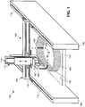
- FIG. 1 shown in Figure 1 is a perspective view of an example of a manufacturing system 100 including an additive manufacturing machine 102 having a printhead 140 configured for layer-by-layer manufacturing of an in-work article 460.
- the in-work article 460 is supported on a table 122, and the printhead 140 is oriented for layer-by-layer manufacturing of the in-work article 460 in a vertical direction.
- the printhead 140 may be oriented for layer-by-layer manufacturing of the in-work article 460 in a horizontal direction or in other directions.
- the printhead 140 is configured to extrude a material onto a substrate 120 and form a new bead 324 during relative movement of the printhead 140 for additive manufacturing of the in-work article 460.
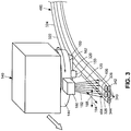
- the manufacturing system 100 further includes at least one profilometer 180 movable with the printhead 140 and configured to continuously or periodically measure an in-work cross-sectional profile 464 ( Figure 3 ) at least of one or more existing beads 340 of the in-work article 460 during forming of the new bead 324.
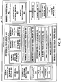
- the manufacturing system 100 additionally includes a control system 200 ( Figure 2 ) having a processor 204 ( Figure 2 ) configured to continuously or periodically generate and record in-work profile data 462 ( Figure 2 ) including the in-work cross-sectional profiles 464 measured by the profilometer 180 at a corresponding plurality of in-work profile locations 466 in the in-work article 460.
- the in-work profile locations 466 of the in-work cross-sectional profiles 464 may be continuously determined and/or automatically recorded in a memory 202 ( Figure 2 ) and may be based on the six-dimensional locational data of the printhead 140 at the time of measurement of the in-work cross-sectional profile 464 by a profilometer 180.
- the six-dimensional locational data of the printhead 140 may include three-dimensional position data (e.g., the x, y, z location of the printhead 140) and three-dimensional angular orientation data (e.g., orientation of the printhead 140 about each of the x, y, and z axes).
- three-dimensional position data e.g., the x, y, z location of the printhead 140
- three-dimensional angular orientation data e.g., orientation of the printhead 140 about each of the x, y, and z axes.
- the control system 200 is additionally configured to continuously or periodically perform a profile comparison of the in-work profile data 462 to reference profile data 472 of a reference article 470.
- the reference profile data 472 includes a reference cross-sectional profile 474 at a plurality of reference profile locations 476.
- the plurality of reference profile locations 476 in the reference article 470 correspond to the plurality of in-work profile locations 466 in the in-work article 460.
- the reference profile data 472 may include nominal profile data 482 containing a plurality of reference cross-sectional profiles 474 at a corresponding plurality of nominal profile locations 486 of a nominal article 480 which may represent the as-designed configuration of the in-work article 460.
- the nominal profile data 482 may include profile-to-void data 488 identifying voids 442 (e.g., Figures 6 , 14 , 21 , 25 , 29 , 33 ) existing at or associated with one or more of the nominal profile locations 486 ( Figure 2 ) in the reference article 470.
- profile-to-void data 488 identifying voids 442 (e.g., Figures 6 , 14 , 21 , 25 , 29 , 33 ) existing at or associated with one or more of the nominal profile locations 486 ( Figure 2 ) in the reference article 470.
- the reference profile data 472 may include simulated profile data 494 of a simulated article 492 that may represent the in-work article 460.
- the simulated article 492 may be a computer model (e.g., a three-dimensional digital definition 220) of the in-work article 460.
- the simulated profile data 494 may include a plurality of simulated cross-sectional profiles 496 at a corresponding plurality of simulated profile locations 498 and may additionally include profile-to-void data 488 identifying voids 442 in the simulated article 492 at one or more of the simulated profile locations 498.
- the simulated cross-sectional profile 496 may be generated by analysis or querying of the simulated article 492 regarding profile features 400 of simulated cross-sectional profiles 496 at a plurality of simulated profile locations 498 in the simulated article 492.
- the control system 200 may adjust, based on the profile comparison, one or more bead forming parameters 240 in a manner reducing a nonconformity 430 in the in-work article 460 to a size no larger than the nonconformity 430 at a corresponding one or more of the simulated profile locations 498 in the simulated article 492.
- the reference profile data 472 may include machine-learned profile data 490 which may contain a plurality of in-work cross-sectional profiles 464 previously measured by the profilometer 180 for use by the control system 200 to predict and mitigate nonconformities 430 in the in-work article 460.
- control system 200 ( Figure 2 ) is configured to adjust (e.g., via a controller 206), based on the profile comparison, one or more bead forming parameters 240, and cause the printhead 140 to form the new bead 324 according to the bead forming parameters 240 in a manner resulting in a reduction in a size of a nonconformity 430 (e.g., Figures 17, 19, 21 , 23 , 27 , 31 , etc.) associated with forming the new bead 324 at one or more of the in-work profile locations 466 relative to the size of the nonconformity 430 otherwise occurring without adjusting the bead forming parameters 240.
- a nonconformity 430 e.g., Figures 17, 19, 21 , 23 , 27 , 31 , etc.
- adjustment of the one or more bead forming parameters 240 may be performed on an as-needed basis, such as when the in-work cross-sectional profile 464 deviates from the reference cross-sectional profile 474 to an extent that the control system 200 determines that a nonconformity 430 exceeding a predetermined size will occur in the in-work article 460 absent adjustment of the bead forming parameters 240.
- a nonconformity 430 in the in-work article 460 may include a gap 432 (e.g., Figures 17 and 19 ) between a new bead 324 and an existing bead 340, a notch 420 (e.g., Figure 21 ) exceeding a threshold notch size (e.g., 0.10 inch) between existing beads 340, a bead mislocation 434 (e.g., Figure 16 ), an existing bead 340 that is a mis-sized bead 408 (e.g., Figures 18 and 20 ), and/or a void 442 (e.g., Figure 21 ) exceeding a threshold size (e.g., 0.10 inch).
- a threshold notch size e.g. 0.10 inch
- the printhead 140 may be movably supported by a head moving system 104 configured to move the printhead 140 relative to the substrate 120 (e.g., table 122) during additive manufacturing of the in-work article 460.
- the head moving system 104 may be configured as a gantry 106 having a horizontal beam 110 that may be movable along horizontal tracks 112 or rails respectively of a pair of base members 108 which may be supported on a factory floor.
- the head moving system 104 may include a vertical beam 114 to which the printhead 140 may be coupled.
- the vertical beam 114 may include vertical tracks 116 or rails for vertical movement of the printhead 140.
- the gantry 106 may enable movement of the printhead 140 along three mutually perpendicular axes according to a preprogrammed head path for manufacturing the in-work article 460.
- the head moving system 104 may be configured as a robotic device having a robotic arm configured to move the printhead 140 along a preprogrammed head path.
- control system 200 may include a controller 206 configured to control the head moving system 104 for controlling movement (e.g., path parameters 242 - the head path, the head travel speed, the head orientation) of the printhead 140 according to computer readable program instructions 224 based on a three-dimensional digital definition 220 (e.g., a computer-aided-design (CAD) model 222) of the in-work article 460.
- the computer-aided-design (CAD) model 222 may also function as the simulated article 492 from which the simulated profile data 494 is generated for comparison to the in-work profile data 452 during manufacturing of an in-work article 460.
- control system 200 may be configured to control the operation (e.g., process parameters 244) of the printhead 140 in forming the new bead 324 based on the computer readable program instructions 224.
- the in-work article 460 may have a net shape or a near-net shape that may be trimmed, machined and/or otherwise processed into a final shape.
- a beneath layer 344 may be described as an existing layer 342 containing one or more existing beads 340 upon which the new bead 324 is formed.
- An adjacent bead 328 may be described as an existing bead 340 alongside of which the new bead 324 is to be formed in the new layer 326.
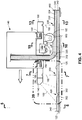
- Figure 4 is a sectional view of the printhead 140 of Figure 3 showing the printhead 140 forming a new bead 324 on top of an existing layer 342 of existing beads 340. Also shown in Figure 4 are the terminating ends 362 of the existing layer 342 upon which the new bead 324 is being formed.
- the printhead 140 may include at least one nozzle 150 for extruding material, and may also include a compression device 160 for at least partially flattening the material after extrusion.
- the nozzle 150 may extrude a pre-flattened bead 320 of the material onto the substrate 120.
- the substrate 120 may be a table 122 upon which the in-work article 460 is manufactured, or the substrate 120 may be an existing layer 342 of existing beads 340 previously formed by the printhead 140.
- the nozzle 150 may have a circular cross-sectional shape resulting in a cylindrical shape of the pre-flattened bead 320.
- the nozzle 150 may have an alternative cross-sectional shape such as a rectangular cross-sectional shape or a square cross-sectional shape for forming the pre-flattened bead 320 in a corresponding shape.
- the printhead 140 may move relative to the table 122 which may be stationary.
- the table 122 may be movable via a table movement system (not shown) in coordination with movement of the printhead 140 during forming of the new bead 324.
- the table 122 may be movable and the printhead 140 may be stationary during forming of a new bead 324.
- the compression device 160 may be configured as a compression roller 162 which may be freely rotatable.
- the compression device 160 is located downstream of the nozzle 150 and may be configured to compress the pre-flattened bead 320 against the substrate 120 to form the new bead 324 as a flattened bead 322.
- the compression device 160 may urge the material of the pre-flattened bead 320 into nesting relation against one or more existing beads 340 in a beneath layer 344 and/or in a new layer 326 being formed as a means to at least partially fill one or more gaps 432 ( Figures 17 and 19 ) or notches 420 ( Figure 9 ) that may extend along a lengthwise direction between the new bead 324 and one or more existing beads 340.
- the compression device 160 may have a smooth surface for imparting a smooth surface finish on the bead top portion of the new bead 324.
- each new bead 324 may be configured to form each new bead 324 with a generally flat or planar bead upper surface for supporting a new bead 324.
- the compression device 160 may be configured to form each new bead 324 with a bead height 404 ( Figure 9 ) that is consistent (e.g., within 10 percent) with the bead height 404 of existing beads 340.
- the compression device 160 may be mounted to a rotatable base 144 of the printhead 140.
- the rotatable base 144 may rotate when the printhead 140 changes direction along the head path as a means to maintain the compression device 160 behind the nozzle 150 at all times during extrusion of the material for flattening the material after extrusion onto the substrate 120.
- the rotatable base 144 may be servo-controlled for changing the orientation of the compression device 160 in correspondence with changes in direction of the printhead 140.
- the compression device 160 may be provided in alternative configurations such as a compression shoe configured to slide over the pre-flattened bead 320 and compress the pre-flattened bead 320 into a flattened bead 322 (i.e., the new bead 324).
- the compression device 160 may be maintained (e.g., via the control system 200) at a temperature that promotes either heating or cooling of the new bead 324 during the flattening process.
- the compression device 160 may be maintained at a temperature that promotes fusing of the new bead 324 to existing beads 340 during the flattening process.
- the compression device 160 may be maintained at a temperature that promotes solidification of the new bead 324 to allow the new bead 324 to support the next layer.
- the printhead 140 may be configured to extrude any one a variety of different types of materials.
- pellets (not shown) of material may be loaded into a hopper (not shown) and melted into molten material that may be forced by a pump (not shown) through the nozzle 150.
- the printhead 140 may be configured to maintain the material at a temperature that allows for extrusion and flattening of the material onto the substrate 120.
- the material may be at an elevated temperature that facilitates extrusion as a pre-flattened bead 320 from the nozzle 150, and allowing the pre-flattened bead 320 to bend from a perpendicular orientation of the nozzle 150 relative to the substrate 120, to a parallel orientation of the pre-flattened bead 320 on the substrate 120.
- materials that the printhead 140 may extrude include glass material, ceramic material, metallic material, polymeric material, or any combination thereof.
- Polymeric material may include thermosetting material or thermoplastic material.
- polymeric material may include acrylonitrile butadiene styrene, polylactic acid, polyphenylene sulfide, NylonTM, polycarbonate, polyether ether ketone (PEEK), polyether ketone ketone PEKK, or any one a variety of other polymeric materials.
- the printhead 140 may be configured to extrude material containing reinforcing fibers (not shown) formed of glass, graphite, ceramic, metallic, and/or polymeric material. Such reinforcing fibers may be provided as short, chopped fibers or as continuous and/or unidirectional reinforcing fibers (not shown) that may be introduced into the polymeric material during feeding of the polymeric material to the nozzle 150.
- metallic (e.g., steel, aluminum, etc.) wire feedstock may be dispensed from a printhead 140 as an alternative to extruding molten material.
- the metallic wire feedstock may be melted with a heating device (not shown) providing a localized high-temperature source for melting the wire feedstock as it is dispensed to form a new bead 324 of material onto a substrate 120.
- a heating device not shown
- a printhead 140 may include a resistance heating element configured to melt the wire feedstock as it is dispensed from the printhead 140 which may allow for shaping into a desired cross-sectional shape.
- the printhead 140 may include an arc-welding torch, a laser, and/or an electron beam to melt the wire feedstock as it is dispensed from the printhead 140 and/or as the wire feedstock contacts the bead laydown point 302.
- the printhead 140 includes at least one profilometer 180 for measuring in-work cross-sectional profiles 464 of the in-work article 460 during layer-by-layer manufacturing.
- one or more of the profilometers 180 may be mounted to the printhead 140 such as to the rotatable base 144 of the printhead housing 142 to allow the profilometers 180 to change orientation in correspondence with changes in the direction of the printhead 140 moving along the head path during the forming of a new bead 324.
- the one or more profilometers 180 may continuously or periodically measure (e.g., in real time) the in-work cross-sectional profile 464 of existing beads 340 in an existing layer 342 located immediately below a new layer 326 in which the new bead 324 is being formed.
- the geometric measurement of the in-work cross-sectional profile 464 may include the in-work cross-sectional profiles 464 of one or more existing beads 340 in a new layer 326 containing the new bead 324, and including an adjacent bead 328 against which the new bead 324 is being formed.
- the one or more profilometers 180 may be provided in any one of a variety of configurations.
- each profilometer 180 may be configured as a non-contact device for measuring a cross-sectional profile.
- the profilometer 180 may be a laser profilometer configured to emit one or more laser beams within a scanning plane 182.
- a laser profilometer may be configured to emit a single laser beam configured to scan back and forth within a scanning angle of a scanning plane 182.
- a laser profilometer may be configured to emit multiple laser beams (e.g., Figure 7 ) within a scanning plane 182.
- a laser profilometer may emit laser beams that impinge at predetermined locations of a surface contour being scanned.
- a laser profilometer may emit laser beams that impinge on a minimum of 20 points uniformly distributed across a surface contour defined by existing beads 340 of which the in-work cross-sectional profile 464 is being measured.
- a laser profilometer may be configured as a linear scanning profilometer configured to scan in a two-dimensional direction.
- one or more of the laser profilometers may be configured to scan a laser beam along scanning plane 182 oriented in a lateral direction 184 ( Figure 3 ) perpendicular to a direction of travel of the printhead 140, or along a longitudinal direction 188 ( Figure 3 ) parallel to the direction of travel of the printhead 140, or in a combination of the lateral direction 184 and the longitudinal direction 188 or any other direction.
- a laser profilometer is a high-speed laser profile designated as the LJ-V7000 Series available from Keyence Corporation of Itasca, Illinois.
- a laser profilometer may use a blue laser (e.g., frequency band of 450-490 nm) to provide for relatively high accuracy of measurement of in-work cross-sectional profiles 464.
- the printhead 140 may include one or more laser profilometers that use lasers operating in other frequencies, such as a red laser.
- the printhead 140 includes one or more profilometers 180 configured to measure in-work cross-sectional profiles 464, as mentioned above.
- the profilometers 180 may be mounted to the printhead 140 at one or more locations relative to the bead laydown point 302.
- the printhead 140 may include one or more profilometers 180 configured to measure at least one in-work cross-sectional profile 464 representing the contour of the existing beads 340 at a pre-laydown location 300 upstream (e.g., up to several inches or more) of the bead laydown point 302.
- the bead laydown point 302 may be defined as the location where the leading edge portion of pre-flattened bead 320 first makes contact with the substrate 120 during extrusion of material from the nozzle 150.
- the printhead 140 may also include one or more profilometers 180 at a pre-flattened location 304 between the nozzle 150 and the compression device 160 for measuring an in-work cross-sectional 464 of the contour of the pre-flattened bead 320 and the existing beads 340 over which and/or against which the new bead 324 is being formed.
- a printhead 140 may additionally include one or more profilometers 180 at a post-flattened location 306 immediately (e.g., up to several inches or more) downstream of the compression device 160 for measuring an in-work cross-sectional profile 464 of the contour of the new bead 324 and the existing beads 340 located beneath and adjacent to the new bead 324.
- the printhead 140 may include one or more profilometers 180 at any one of the above-describe locations.
- the profilometers 180 may be configured to measure in-work cross-sectional profiles 464 along any one of a variety of scanning planes 182.
- Figure 4 shows an example of printhead 140 having two profilometers 180 at the pre-laydown location 300, including a lateral profilometer 186 configured to measure an in-work cross-sectional profile 464 along a lateral direction 184 ( Figure 3 ) by scanning a laser along a scanning plane 182 oriented perpendicular to the direction of travel of the printhead 140, and a longitudinal profilometer 190 configured to measure an in-work cross-sectional profile 464 along a longitudinal direction 188 ( Figure 3 ) by scanning a laser along a scanning plane 182 oriented parallel to the direction of travel of the printhead 140.
- a lateral profilometer 186 configured to measure an in-work cross-sectional profile 464 along a lateral direction 184 ( Figure 3 ) by scanning a laser along a scanning plane 182 oriented perpendicular to the direction of travel of the printhead 140
- a longitudinal profilometer 190 configured to measure an in-work cross-sectional profile 464 along a longitudinal direction 188 ( Figure 3 ) by scanning a laser
- Measuring the in-work cross-sectional profile 464 along the longitudinal direction 188 allows for measuring the contour of the notch 420 between terminating ends 362 of existing beads 340 ( Figures 4 and 40 ), or between the intersection of a terminating end 362 of an existing bead 340 with the side of another existing bead 340 (e.g., Figure 41 ), as described below.
- Figure 5 shown in Figure 5 is a front view of an example of a printhead 140 having a single nozzle 150 configured for forming a single new bead 324 ( Figure 13 ).
- Figure 6 is a front view of an example of a printhead 140 having a plurality of nozzles 150 for forming a corresponding plurality of new beads 324.
- the plurality of nozzles 150 are arranged in a linear array and may be configured to simultaneously extrude material onto the substrate 120 to simultaneously form a corresponding plurality of pre-flattened beads 320.
- the printhead 140 may include at least one compression device 160 such as a compression roller 162 configured to simultaneously flatten the pre-flattened beads 320 into flattened beads 322 (e.g., new beads 324) preferably arranged in side-by-side contacting relation with each other.
- a compression roller 162 configured to simultaneously flatten the pre-flattened beads 320 into flattened beads 322 (e.g., new beads 324) preferably arranged in side-by-side contacting relation with each other.
- Figure 7 is a sectional view of an example of a profilometer 180 at a pre-laydown location 300.
- the profilometer 180 is shown scanning a laser along a scanning plane 182 oriented parallel to the lateral direction 184 ( Figure 3 ) for measuring an in-work cross-sectional profile 464 ( Figure 8 ) of the existing beads 340 of an in-work article 460.
- Figure 8 shows an example of the in-work cross-sectional profile 464 measured by the profilometer 180 at the pre-laydown location 300.
- the in-work cross-sectional profile 464 represents the surface contour of the existing beads 340 in a beneath layer 344 over which a new bead 324 ( Figures 3-4 ) is to be formed, and also represents the surface contour of an adjacent bead 328 (e.g., an existing bead 340) against which the new bead 324 is to be positioned.
- Figure 9 is a magnified view of the in-work cross-sectional profile 464 of Figure 8 showing the profile features 400 of the in-work cross-sectional profile 464.
- the profile features 400 may include the bead lateral location 402 of the existing beads 340 ( Figure 8 ) in the beneath layer 344 ( Figure 8 ) and the new layer 326 ( Figure 8 ), and may additionally include the bead size and the bead shape of the existing beads 340.
- the bead size may include the bead width 406 and the bead height 404.
- the profile features 400 may include the notch size and the notch shape of each notch 420 between existing beads 340.
- the notch size may include the notch width 426 and the notch depth 422.
- the control system 200 ( Figure 2 ) is configured to continuously or periodically perform a profile comparison of the in-work profile data 462 to reference profile data 472 of a reference article 470, and make necessary adjustments to one or more bead forming parameters 240 ( Figure 2 ) to reduce or prevent the occurrence of nonconformities 430 (e.g., Figures 17, 19, 21 , etc.) in the in-work article 460.
- the bead forming parameters 240 may include path parameters 242 and/or process parameters 244.
- Path parameters 242 may include the head path of the printhead 140.
- the head path may define directions for movement and orientation of the printhead 140 and/or movement and orientation of the substrate 120 during printing of an in-work article 460.
- the head path may include multiple path segments which may be described as a sequence of directions and corresponding distances of travel along which the printhead 140 moves during layer-by-layer manufacturing of the in-work article 460.
- the head path may be defined by the computer readable program instructions 224 ( Figure 2 ) for operation of the head manufacturing system 100.
- the path parameters 242 may also include the head travel speed of the printhead 140 along each path segment of the head path.
- the bead forming parameters 240 may also include process parameters 244 regarding processing operations of the printhead 140 during movement along the head path.
- the process parameters 244 may include a material temperature at which the material is extruded onto the substrate 120.
- the material may be extruded at a temperature that allows for fusing of a new bead 324 to existing beads 340, and that also promotes solidification of the new bead 324 to an extent allowing the new bead 324 to support another layer of material.
- the process parameters 244 may also include a material feed rate (e.g., volumetric) at which material passes through a nozzle 150 and is extruded onto the substrate 120.
- Controlling the material feed rate may provide a means to control the bead width 406 (e.g., Figure 12 ) of the pre-flattened bead 320 which therefore affects the bead size of the new bead 324.
- the printhead 140 may be configured to extrude a pre-flattened bead 320 having a bead diameter in the range of 0.12 inch to 3.0 inches although larger and smaller diameters are possible.
- the pre-flattened bead 320 may be extruded in a bead diameter of from 0.25-1.0 inch.
- the material feed rate may be synchronized with the head travel speed to achieve a desired size of the pre-flattened bead 320 which, in turn, affects the size (e.g., the bead width 406 and the bead height 404) of the new bead 324 (i.e., the pre-flattened bead 320 after flattening).
- the process parameters 244 may also include the bead lay rate (e.g., inches per unit time) at which a new bead 324 is formed on the substrate 120, and which may be a function of the head travel speed and the material feed rate as described above. Additional process parameters 244 may include the temperature of the compression device 160 (e.g., compression roller 162) of the printhead 140 for increasing or decreasing the temperature of the material during flattening of the pre-flattened bead 320 by the compression device 160.
- the compression device 160 e.g., compression roller 162
- the temperature of the compression device 160 may be increased to slightly reduce the viscosity of the material to promote the material filling in the notches 420 between the new bead 324 and the existing beads 340 and/or to promote the fusing of the new bead 324 to the existing beads 340.
- Other process parameters 244 include the vertical position of the compression device 160 for controlling the bead height 404 ( Figure 19 ) of the new bead 324.
- the compression device 160 may be vertically adjustable to allow for adjustment of the bead height 404 such that the new bead 324 is substantially equal to (e.g., within 10 percent of) the bead height 404 of existing beads 340.
- the process parameters 244 may also include the compaction pressure applied by the compression device 160 onto the pre-flattened bead 320 against the substrate 120 and against one or more existing beads 340 during the flattening of the pre-flattened bead 320.
- control system 200 may perform the profile comparison by comparing the profile features 400 ( Figure 9 ) of an in-work cross-sectional profile 464 of an in-work article 460 to corresponding profile features 400 of a reference cross-sectional profile 474 of a reference article 470 ( Figure 2 ).
- Profile features 400 that may be included in the profile comparison include the above-mentioned bead lateral location 402, bead size, bead shape, notch size, and notch shape.
- the in-work article 460 is of nominal construction and may represent an as-designed version of the in-work article 460.
- the existing beads 340 in Figure 7 may be sized, shaped, and positioned within design specifications such that the profile features 400 in Figure 9 represent profile features 400 of a nominal cross-sectional profile 484 ( Figure 2 ) of a nominal article 480 ( Figure 2 ).
- the nominal article 480 may be the reference article 470 against which the in-work article 460 is continuously compared during the manufacturing of the in-work article 460.
- the reference profile data 472 may be simulated profile data 494 of a simulated article 492, which may be a computer model (e.g., a CAD model 222) of the in-work article 460 and which may represent the above-mentioned as-designed version of the in-work article 460.
- the simulated profile data 494 may include simulated cross-sectional profiles 496 taken at a plurality of simulated profile locations 498.
- the simulated profile data 494 may additionally include profile-to-void data 488 including size and location information on voids 442 (if any) in the simulated article 492 at one or more simulated profile locations 498.
- the simulated cross-sectional profile 496 may be generated by analysis of the simulated article 492.
- the simulated article 492 may be queried and/or measurements of profile features (e.g., bead size, bead shape, notch size, notch shape) may be extracted from simulated cross-sectional profiles 496 at a plurality of simulated profile locations 498 in the simulated article 492.
- the measurements may be stored in the memory 202 and accessed during the profile comparison performed by the control system 200 during manufacturing of an in-work article 460 for assessing whether one or more bead forming parameters 240 require adjustment in order to reduce a nonconformity 430 in the in-work article 460 to a size no larger than the nonconformity 430 at a corresponding simulated profile location 498 in the simulated article 492.
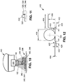
- Figure 10 is a sectional view of an example of a profilometer 180 of a printhead 140 at a pre-flattened location 304 and showing the profilometer 180 scanning a laser along a scanning plane 182 oriented parallel to the lateral direction 184 ( Figure 3 ).
- Figure 11 shows an example of the in-work cross-sectional profile 464 measured by the profilometer 180 at the pre-flattened location 304.
- the in-work cross-sectional profile 464 represents the surface contour of the pre-flattened bead 320 and the existing beads 340 in the beneath layer 344 over which the pre-flattened bead 320 is located, and also represents the surface contour of the adjacent bead 328 against which the new bead 324 ( Figure 13 ) is to be positioned after the pre-flattened bead 320 has been flattened by the compression device (not shown).
- Figure 12 is a magnified view of the in-work cross-sectional profile 464 of Figure 11 and showing the above-mentioned profile features 400 including the bead width 406 (e.g., bead diameter) and the bead lateral location 402.
- the in-work article 460 in Figures 10-12 may be of nominal construction such that the profile features 400 in Figure 12 may represent the profile features 400 of a nominal cross-sectional profile 484 ( Figure 2 ) of a nominal article 480 ( Figure 2 ) that the control system 200 may use as the reference article 470 in the profile comparison.
- the bead centerline 360 of the pre-flattened bead 320 is aligned with the bead centerline 360 of the existing bead 340 over which the pre-flattened bead 320 is placed.
- Figure 13 is a sectional view of an example of a profilometer 180 at a post-flattened location 306 and showing the profilometer 180 scanning a laser along the lateral direction 184 ( Figure 3 ).
- Figure 14 shows an example of the in-work cross-sectional profile 464 measured by the profilometer 180 at the post-flattened location 306.
- the in-work cross-sectional profile 464 represents the surface contour of the new bead 324 resulting from the flattening of the pre-flattened bead 320 ( Figure 10 ), and additionally represents the surface contour of the existing beads 340 in the beneath layer 344 and the adjacent bead 328 against which the new bead 324 is positioned.
- Figure 15 is a magnified view of the in-work cross-sectional profile 464 of Figure 14 and showing the profile features 400 including the bead lateral location 402 and bead size of the new bead 324 and the existing beads 340, and additionally showing the notch size and notch shape of the notch 420 between the new bead 324 and the existing beads 340.
- the in-work article 460 shown in Figures 13-15 may be of nominal construction such that the profile features 400 in Figure 15 represent the profile features 400 of a nominal cross-sectional profile 484 ( Figure 2 ) of a nominal article 480 ( Figure 2 ).
- the bead centerline 360 of the new bead 324 may be aligned with the bead centerline 360 of the existing bead 340 over which the new bead 324 is formed.
- the bead width 406 and the bead height 404 of the new bead 324 may be equivalent respectively to the bead width 406 and the bead height 404 of the existing beads 340.
- control system 200 may use machine-learned profile data 490 ( Figure 2 ) which may include a plurality of in-work cross-sectional profiles 464 previously-generated (e.g., previously measured and recorded) at a corresponding plurality of in-work profile locations 466 during manufacturing of the in-work article 460.
- the control system 200 may be configured to continuously compare the in-work cross-sectional profiles 464 and identify, via machine learning, one or more patterns of nonconformities 430 associated with manufacturing the in-work article 460.
- control system 200 may identify a pattern of bead mislocation 434 of one or more existing beads 340 and/or of the new bead 324 at one or types of locations in the in-work article 460, such as at certain types of corners (i.e., locations where the beads change direction) of the in-work article 460, or at other locations.
- control system 200 may identify a pattern of mis-sized beads 408 (e.g., an undersized bead 410 - Figure 18 ; an oversized bead 412 - Figure 20 ) at one or more types of locations in the in-work article 460.
- the control system 200 may identify a pattern of gaps 432 occurring at certain types of locations in the in-work article 460.
- the control system 200 may be configured to adjust, based on the patterns, one or more of the bead forming parameters 240 associated with the forming of a new bead 324 in a manner to reduce or prevent the occurrence of the nonconformities 430 identified in the pattern. For example, upon identifying a pattern of bead mislocation 434 at a certain type of location or geometric feature (e.g., at a corner) in the in-work article 460, the control system 200 may adjust the head path as the printhead 140 approaches the location identified in the pattern as a means to prevent further mislocation of the new bead 324 and thereby reduce or prevent the occurrence of a void 442 at the location identified in the pattern.
- control system 200 may adjust one or more process parameters 244 such as the head travel speed and/or the material feed rate as the printhead 140 approaches the location identified in the pattern as a means to locally increase the bead size of the new bead 324 at the location identified in the pattern.
- Figure 16-21 show an in-work article 460 for the purpose of illustrating several examples of various types of nonconformities 430 that may occur during manufacturing of an in-work article 460.
- Figure 16 is a cross-sectional view of an example of a bead mislocation 434 in which the pre-flattened bead 320 is mislocated relative to the existing beads 340 which include existing beads 340 in a beneath layer 344 over which the pre-flattened bead 320 is extruded, and also includes an adjacent bead 328 in the new layer 326 containing the pre-flattened bead 320.
- the bead centerline 360 of the pre-flattened bead 320 is offset from the bead centerline 360 of the existing bead 340 in the existing layer 342 over which the pre-flattened bead 320 is extruded.
- Figure 17 is a cross-sectional view of the existing beads 340 and the pre-flattened bead 320 after being flattened to form the new bead 324, and illustrating a gap 432 between the new bead 324 and the adjacent bead 328 (e.g., an existing bead 340) as a result of the bead mislocation 434 ( Figure 16 ) of the pre-flattened bead 320.
- Such gap 432 may result in a void (not shown) in the in-work article 460 when completed.
- Figure 18 is a cross-sectional view of an example of a nonconformity 430 in which the pre-flattened bead 320 is placed at the correct bead lateral location 402, but the adjacent bead 328 (i.e., the existing bead 340 against which the pre-flattened bead 320 is placed) is undersized (e.g., a mis-sized bead 408).
- the undersized bead 410 may have occurred as a result of an error in one or more of the bead forming parameters 240 ( Figure 2 ) during forming of the adjacent bead 328.
- the error in the bead forming parameters 240 may include an excessively high head travel speed of the printhead 140 ( Figure 2 ) and/or an excessively low material feed rate at which is passed (e.g., pumped) through the nozzle 150 ( Figure 3 ) of the printhead 140.
- Figure 19 is a cross-sectional view of the existing beads 340 and pre-flattened bead 320 of Figure 18 after flattening to form the new bead 324, and which results in a gap 432 between the new bead 324 and the adjacent bead 328 as a result of the adjacent bead 328 being undersized.
- a gap 432 may result in a void 442 in the in-work article 460 when completed.
- Figure 20 is a cross-sectional view of an example of a nonconformity 430 in which the pre-flattened bead 320 is properly located but the adjacent bead 328 is oversized (e.g., a mis-sized bead 408), and which may be the result of an error in one or more bead forming parameters 240 including an error in the head travel speed and/or an error in the material feed rate of the printhead 140 during extrusion of the pre-flattened bead 320.
- Figure 21 is a cross-sectional view of the new bead 324 in Figure 20 being mislocated as a result of the adjacent bead 328 being oversized.
- the bead centerline 360 of the new bead 324 may be offset from the bead centerline 360 of the existing bead 340 in the beneath layer 344.
- subsequently formed new beads 324 may also be mislocated.
- FIG. 21 Also shown in Figure 21 is an example of a nonconformity 430 in the form of a void 442, one or more of which may remain in the in-work article 460 after manufacturing is complete and the in-work article 460 has cured or solidified.
- a void 442 may occur between the surfaces of two or more existing beads 340 of the in-work article 460.
- an in-work article 460 may include any number of voids 442 extending along any portion of the in-work article 460.
- a void 442 may also occur as a result of a gap 432 between a new bead 324 and an adjacent bead 328 such as the gap 432 illustrated in Figures 17 and 19 .
- a void 442 may also occur as a result of a surface cavity 436 (e.g., Figures 39 and 41 ) on a surface of an existing bead 340 during its formation, as described below.
- voids 442 may be detected and measured by nondestructive evaluation (e.g., x-ray imaging, computed tomography imaging, etc.) of a reference article 470 and/or by physical inspection of a reference article 470.
- a reference article 470 may be an in-work article 460 that has been completed and designated as a nominal article 480 for use as a reference standard against which future in-work articles 460 may be compared during manufacturing as a means to assess whether adjustment of bead forming parameters 240 is necessary.
- a nominal article 480 may be manufactured using the same type of material and the same type of printhead 140 to be used during future manufacturing of in-work articles 460.
- a nominal article 480 may be physically sectioned (e.g., in a laboratory) and nominal cross-sectional profiles 484 may be measured at a plurality of nominal profile locations 486 within the nominal article 480 to generate the above-described nominal profile data 482 for comparison by the control system 200 to in-work profile data 462 continuously generated (using one or more profilometers 180) during manufacturing of an in-work article 460.
- the measurement values of the profile features 400 may be adjusted to compensate for shrinkage of the bead material during cool down.
- the material may be at a higher temperature than the existing beads 340 and/or higher than ambient temperature.
- the new bead 324 of material may shrink as it cools to room temperature.
- the profile comparison of the in-work profile data 452 e.g., when the material is hot
- the nominal profile data 482 e.g., reference profile data 472
- an adjustment factor may be applied to increase the value of each profile feature 400 (e.g., of bead width, notch width, etc.) of the nominal article 480 by an amount equal to the shrinkage of such profile feature due to cool down of the material.
- control system 200 is configured to adjust, based on the profile comparison, one or more bead forming parameters 240 in a manner reducing a nonconformity 430 (e.g., a void 442, a gap 432, a bead mislocation 434, a mis-sized bead 408) potentially occurring at one or more in-work profile locations 466 to a size no larger than the nonconformity 430 at a corresponding nominal profile locations 486 in the nominal article 480.
- a nonconformity 430 e.g., a void 442, a gap 432, a bead mislocation 434, a mis-sized bead 408
- the nominal profile data 482 ( Figure 2 ) (e.g., reference profile data 472) includes nominal cross-sectional profiles 484 and the corresponding three-dimensional location (i.e., the nominal profile location) of each nominal cross-sectional profile 484 that is measured.
- the nominal profile data 482 includes data on nonconformities 430 associated with one or more of the nominal cross-sectional profiles 484.
- nonconformities 430 such as voids 442 in the nominal article 480 may be detected and measured during evaluation of the nominal article 480.
- Voids 442 may be measured for void 442 size (e.g., void 442 width and/or void 442 cross-sectional area).
- the void data may be recorded as profile-to-void data 488 along with the nominal cross-sectional profile 484 to which each void 442 is associated.
- the profile-to-void data 488 may be limited to data on voids 442 that are larger than a threshold size. For example, voids 442 having a void 442 width of less than 0.10 inch in the lateral direction 184 may be excluded from the profile-to-void data 488.
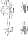
- Figure 22 shows an example of an in-work cross-sectional profile 464 of the existing beads 340 and illustrating the mislocation of the pre-flattened bead 320 of Figure 16 as may be measured by one or more of the above-described profilometers 180 ( Figure 4 ) of the printhead 140 ( Figure 4 ).
- the in-work cross-sectional profile 464 may be measured by a profilometer 180 mounted to the printhead 140 at the pre-laydown location 300 shown in Figure 4 .
- Figure 23 is a magnified view of the in-work cross-sectional profile 464 of Figure 22 showing the profile features 400 (e.g., bead lateral location 402, bead size, notch size, etc.) of the in-work cross-sectional profile 464.
- control system 200 is configured to perform a profile comparison by comparing at least one profile feature 400 of the in-work cross-sectional profile 464 measured at one or more in-work profile locations 466 to a corresponding profile feature 400 of a reference cross-sectional profile 474 at a corresponding reference profile location 476 for determining which, if any, of the bead forming parameters 240 require adjustment in order to reduce or prevent nonconformities 430 that may otherwise occur in the in-work article 460 at the in-work profile location 466 of the in-work cross-sectional profile 464.
- the in-work profile locations 466 of the in-work cross-sectional profile 464 may be automatically correlated (e.g., by the control system 200) to a three-dimensional location of the printhead 140 at the time of measurement of the in-work cross-sectional profile 464 by one or more profilometers 180.
- the manufacturing system 100 may include one or more encoders (not shown) that may be used by the head moving system 104 (e.g., the gantry 106 in Figure 1 ; a robotic device - not shown) in moving the printhead 140 along the head path. Such encoders may continuously transmit the printhead positional data to the control system 200 for continuous association by the control system 200 to in-work cross-sectional profile 464 measured by the one or more profilometers 180.
- the profile features 400 may include the bead lateral location 402, the bead size, and/or the bead shape of one or more beads defining the cross-sectional profile of at least one of a new layer 326 and a beneath layer 344 located directly below the new layer 326 in which the new bead 324 is to be formed.
- the bead lateral location 402 may be that of the existing beads 340, the pre-flattened bead 320, and/or the new bead 324.
- the bead lateral location 402 may be measured relative to the bead centerline 360 of a pre-flattened bead 320 and the bead centerline 360 of one or more existing beads 340 (e.g., in a beneath layer 344, or of an adjacent bead 328), or between the bead centerline 360 of a new bead 324 and the bead centerline 360 of one or more existing beads 340.
- the profile features 400 may additionally include the bead size such as the bead width 406 and/or the bead height 404 of the existing beads 340, the pre-flattened bead 320, and/or the new bead 324.
- the profile features 400 may include the bead shape (e.g., cross-sectional shape - rectangular, square, circular, etc.) of the existing beads 340, the pre-flattened bead 320, and/or the new bead 324.
- bead shape e.g., cross-sectional shape - rectangular, square, circular, etc.
- the profile features 400 may include the notch size and/or the notch shape of one or more notches 420 or dips that may exist in the surface profile between beads that define the cross-sectional profile.
- the control system 200 may be configured to record notches 420 having a notch size that exceeds a threshold value (e.g., greater than 0.10 inch).
- the notch size may include the notch depth 422 ( Figure 23 ) which may be defined as the vertical distance between the notch apex 424 ( Figure 23 ) and the top surface of at least one of the existing beads 340 between which the notch 420 is located.
- the notch size may also include the notch width 426 ( Figure 23 ) which may be defined as the maximum horizontal width of the notch 420 which may typically be located proximate the top surfaces of the existing beads 340 that define the notch 420.
- the notch size may also be defined in terms of notch cross-sectional area.
- the notch shape may be defined in terms of the radius of one or both of the opposing sides of the notch 420.
- the bead lateral location 402, the bead shape, and/or the bead size of one or more existing beads 340 defining the in-work cross-sectional profile 464 at one or more in-work profile locations 466 may be compared to the bead lateral location 402, the bead shape, and the bead size respectively of corresponding ones of the existing beads 340 which define the reference cross-sectional profile 474 at the corresponding reference profile location 476.
- the notch size and the notch shape between existing beads 340 defining the in-work cross-sectional profile 464 at one or more in-work profile locations 466 may be compared to the bead lateral location 402, the bead shape, and the bead size respectively of corresponding ones of the existing beads 340 defining the reference cross-sectional profile 474 at the corresponding reference profile location 476.
- the profile comparison performed by the control system 200 may include comparing the sizes and/or shapes of any one or more of the above-noted profile features 400.
- the profile features 400 of the in-work cross-sectional profile 464 may include the bead lateral location 402 and the bead size (e.g., bead width 406) of the pre-flattened bead 320 and the existing beads 340.
- the profile features 400 may also include the notch size of the notches 420 between the existing beads 340.
- the bead centerline 360 of the pre-flattened bead 320 is offset from the bead centerline 360 of the existing bead 340 located beneath the pre-flattened bead 320.
- Figure 24 is a cross-sectional view of the existing beads 340 and pre-flattened bead 320 represented in Figures 22-23 .
- the control system 200 is configured to adjust the head path of the printhead 140 ( Figure 3 ) and cause lateral repositioning of the printhead 140 in a manner causing the pre-flattened bead 320 to be extruded nearer to the adjacent bead 328. After adjustment of the head path by the control system 200, the adjusted head path becomes the new head path.
- Figure 25 shows the new bead 324 (i.e., the pre-flattened bead 320 after flattening) in side-by-side contacting relation with the adjacent bead 328, demonstrating the avoidance of a gap 432 (e.g., Figure 17 ) that may otherwise occur between the new bead 324 and the adjacent bead 328 if the bead forming parameters 240 were not adjusted.
- a gap 432 e.g., Figure 17
- Figure 26 shows an example of an in-work cross-sectional profile 464 of the existing beads 340 and the pre-flattened bead 320 of Figure 18 as may be measured by one or more profilometers 180 mounted at the pre-flattening location shown in Figure 4 .
- Figure 26 illustrates the adjacent bead 328 (e.g., existing bead 340) as an undersized bead 410.
- Figure 27 is a magnified view of the in-work cross-sectional profile 464 of Figure 26 showing the profile features 400 (e.g., bead lateral location 402, bead size, notch size, etc.) that the control system 200 may compare with corresponding profile features 400 of the reference article 470 to determine whether the adjustment of one or more bead forming parameters 240 is necessary in order to reduce or prevent nonconformities 430 in the in-work article 460.
- profile features 400 e.g., bead lateral location 402, bead size, notch size, etc.
- Figure 28 is a cross-sectional view of the existing beads 340 and pre-flattened bead 320 of Figure 18 .
- the control system 200 is configured to adjust one or more bead forming parameters 240 such as the head travel speed of the printhead 140 and/or the material feed rate at which material is extruded onto the substrate 120.
- the bead forming parameters 240 may be adjusted in a manner to cause an increase in the bead size of the pre-flattened bead 320 for reducing or preventing the occurrence of a gap 432 (e.g., Figure 19 ) between the new bead 324 and the adjacent bead 328.
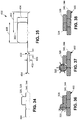
- Figure 29 is a cross-sectional view of the bead configuration of Figure 28 after flattening of the pre-flattened bead 320 to form the new bead 324 which is shown in side-by-side contacting relation with the adjacent bead 328, and demonstrating the avoidance of a gap 432 that would otherwise occur between the new bead 324 and the adjacent bead 328 if the bead forming parameters 240 were not adjusted.
- the adjustment of the bead forming parameters 240 may result in the material of the new bead 324 at least partially filling the notch 420 (e.g., Figure 27 ) between the new bead 324 and the adjacent bead 328.
- the control system 200 may maintain the adjustment of one or more bead forming parameters 240 as long as a nonconformity (e.g., an undersized bead 410) continues to exist.
- a nonconformity e.g., an undersized bead 410
- the control system 200 may maintain a reduced head travel speed and/or an increased material feed rate for the length of time that the profile comparison indicates that the adjacent bead 328 is undersized.
- the control system 200 may revert the bead forming parameters 240 back to their previous settings.
- control system 200 may adjust the settings of one or more bead forming parameters 240 temporarily for as long as a nonconformity 430 (e.g., bead mislocation 434, mis-sized bead 408, occurrence of A gap 432, etc.) exists during the manufacturing of the in-work article 460.
- control system 200 may maintain the adjusted settings of one or more bead forming parameters 240 for the duration of manufacturing of the in-work article 460.
- Figure 30 shows an example of an in-work cross-sectional profile 464 of the existing beads 340 and pre-flattened bead 320 of Figure 20 as may be measured by one or more profilometers 180 mounted at the post-flattened location 306 shown in Figure 4 .
- Figure 30 illustrates the adjacent bead 328 (e.g., existing bead 340) as an oversized bead 412.
- Figure 31 is a magnified view of the in-work cross-sectional profile 464 of Figure 30 showing the profile features 400 (e.g., bead lateral location 402, bead size, notch size, etc.) that the control system 200 may compare with corresponding profile features 400 of a reference article 470 to determine whether the adjustment of one or more bead forming parameters 240 is necessary.
- profile features 400 e.g., bead lateral location 402, bead size, notch size, etc.
- Figure 32 is a cross-sectional view of the existing beads 340 and pre-flattened bead 320 of Figure 20 showing a decrease in the size of the pre-flattened bead 320 as a result of the control system 200 adjusting one or more bead forming parameters 240 (e.g., increasing the head travel speed of the printhead 140 and/or reducing material feed rate) as a means to reduce or avoid a bead mislocation (not shown) of the new bead 324 (e.g., the pre-flattened bead 320 after flattening).
- one or more bead forming parameters 240 e.g., increasing the head travel speed of the printhead 140 and/or reducing material feed rate
- bead mislocation not shown
- Figure 33 is a cross-sectional view of the bead configuration of Figure 32 after the flattening of the pre-flattened bead 320 to form the new bead 324 which is shown in proper side-by-side contacting relation with the adjacent bead 328.
- Figure 34 shows an example of an in-work cross-sectional profile 464 of existing beads 340 as may be measured by one or more profilometers 180 at the pre-laydown location 300 in Figure 4 .
- the adjacent bead 328 i.e., the bead against which the new bead 324 is to be formed
- Figure 35 is a magnified view of the in-work cross-sectional profile 464 of Figure 34 showing the profile features 400 including bead lateral location 402 of which the control system 200 may compare with corresponding profile features 400 of a reference article 470.
- Figure 36 is a cross-sectional view of the existing beads 340 of Figure 34 and showing the pre-flattened bead 320 repositioned nearer to the adjacent bead 328 in response to a profile comparison performed by the control system 200.
- the control system 200 may cause the adjustment of the lateral positioning of the printhead 140 for the purpose of extruding the pre-flattened bead 320 nearer to the adjacent bead 328.
- Figure 38 is a cross-sectional view of the bead configuration of Figure 36 after the flattening of the pre-flattened bead 320 to form the new bead 324 which may be better positioned within the in-work article 460.
- the material of the new bead 324 may fill in the notches (not shown) resulting in improved stackup of the new bead 324 and existing beads 340, and thereby preventing voids (not shown) at the noted location in the in-work article 460
- Figure 37 is a cross-sectional view of the existing beads 340 of Figure 34 and showing the pre-flattened bead 320 at an increased size as a result of the profile comparison and subsequent adjustment of bead forming parameters 240 by control system 200.
- the control system 200 may adjust the head travel speed of the printhead 140 and/or the material feed rate at which material is extruded onto the substrate 120 in a manner to cause an increase in the bead size of the pre-flattened bead 320 as a means to at least partially fill in one or more notches 420 as shown in Figure 35 for reducing or preventing the occurrence of voids 442 in the in-work article 460.
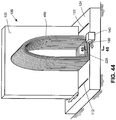
- Figure 39 is a perspective view of an example of a portion of a printhead 140 approaching the opposing terminating ends 362 of existing beads 340.
- the printhead 140 has a lateral profilometer 186 and a longitudinal profilometer 190.
- the lateral profilometer 186 is shown scanning a laser along a scanning plane 182 oriented along the lateral direction 184 which is perpendicular to the direction of travel of the printhead 140.
- the lateral profilometer 186 is shown generating an in-work cross-sectional profile 464 of an existing bead 340 along the lateral direction 184.
- the existing bead 340 has a surface cavity 436 that is represented in the in-work cross-sectional profile 464 measured by the lateral profilometer 186.
- the printhead 140 also has the longitudinal profilometer 190 which is shown scanning a laser along a scanning plane 182 oriented along a longitudinal direction 188 which is parallel to the direction of travel of the printhead 140.
- the longitudinal profilometer 190 is shown generating an in-work cross-sectional profile 464 representing the notch 420 between the terminating ends 362 of the existing beads 340.
- Figure 40 shows the in-work cross-sectional profile 464 along the longitudinal direction 188 and illustrating the notch 420 between the terminating ends 362 of the existing beads 340 of Figure 39 .
- the profiles features 400 may include the notch depth 422 and notch width 426 of the notch 420.
- the control system 200 may determine that one or more of the bead forming parameters 240 require adjustment in anticipation of the printhead 140 approaching the notch 420 between the terminating ends 362 of the existing beads 340.
- the control system 200 may cause one or more bead forming parameters 240 such as head travel speed and/or material feed rate to be temporarily adjusted in a manner to cause a temporary increase in the bead size of the pre-flattened bead 320 ( Figure 28 ) during the time period when the nozzle 150 ( Figure 4 ) passes over the notch 420 as a means to allow the material of the new bead 324 to at least partially fill the notch 420 while maintaining the new bead 324 at a constant bead height 404 ( Figure 29 ).
- bead forming parameters 240 such as head travel speed and/or material feed rate
- Figure 41 shows the in-work cross-sectional profile 464 along the lateral direction 184 and illustrating the surface cavity 436 in the existing bead 340 of Figure 39 .
- the profile features 400 may include the cavity depth 440 and the cavity width 438 of the surface cavity 436 in addition to the bead size and bead shape of the existing bead 340.
- control system 200 may determine that the bead forming parameters 240 must be adjusted in order to temporarily increase the volume of material in the pre-flattened bead 320 in order to allow the material to at least partially fill the surface cavity 436 for the purpose of reducing or preventing the occurrence of a void 442 in the in-work article 460 at the noted location.
- Figure 42 is a perspective view of an example of a portion of a printhead 140 approaching a location where a terminating end 362 of an existing bead 340 terminates at the side of another existing bead 340.
- the printhead 140 has a lateral profilometer 186 and a longitudinal profilometer 190 respectively measuring in-work cross-sectional profiles 464 respectively along the lateral direction 184 ( Figure 39 ) and along the longitudinal direction 188 ( Figure 39 ).
- the in-work cross-sectional profile 464 taken along the longitudinal direction 188 includes a notch 420 between the terminating end 362 of one existing bead 340 and the side of the other existing bead 340.
- Figure 43 shows the in-work cross-sectional profile 464 taken along the longitudinal direction 188 and includes profile features 400 including notch width 426 and notch depth 422 of the notch, and further includes the geometry of the intersecting beads and the surface of the table 122 upon which the existing beads 340 are supported.
- the control system 200 may determine that adjustment is necessary for one or more bead forming parameters 240 to causes a temporary increase in the bead size of the pre-flattened bead 320 during the time period when the nozzle 150 passes over the notch 420 in order to allow the material to at least partially fill the notch 420.
- control system 200 may determine that adjustment of one or more the bead forming parameters 240 is necessary for any one a variety of reasons, and not solely for the purpose of at least partially filling notches 420 between existing beads 340 or for reducing or preventing bead mislocations 434.
- Figure 44 is a perspective view of an example of a manufacturing system 100 in which the in-work article 460 is supported on a horizontal surface of a tool 124 and the printhead 140 is oriented for layer-by-layer manufacturing in a horizontal direction.
- the base of the in-work article 460 is attached to the table 122 which is vertically oriented and which is horizontally movable along the horizontal tracks 112 of the tool 124.
- the table 122 moves incrementally along the horizontal tracks 112, pulling the in-work article 460 with it as the in-work article 460 slides along the horizontal surface of the tool 124.
- Figure 45 is a perspective view of the printhead 140 (head moving system intentionally omitted) and a portion of the existing beads 340 and tool 124 of Figure 45 . Also shown is a profilometer 180 measuring the in-work cross-sectional profile 464 of the existing beads 340 along a lateral direction 184 which is perpendicular to the direction of travel of the printhead 140 during forming of a new bead 324.
- Figure 46 is a magnified sectional view of a portion of the existing beads 340 and tool 124 of Figure 45 showing the in-work cross-sectional profile 464 measured by the profilometer 180. Also shown are the profile features 400 of the in-work cross-sectional profile 464 including the notch width 426 and notch depth 422 of the notches 420.
- the control system 200 may compare the profile features 400 with corresponding profile features 400 of a reference article 470 (not shown) to determine whether the adjustment of one or more bead forming parameters 240 is necessary in order to reduce or prevent nonconformities 430 in the in-work article 460. For example, the control system 200 may determine if adjustment of the head path is required to maintain the side of the new bead 324 in alignment with the surface of the tool 124 indicated in Figure 46 .
- the control system 200 may use machine-learned profile data 490 as the reference profile data 472 for comparison to the in-work profile data 462.
- the machine-learned profile data 490 includes a plurality of in-work cross-sectional profiles 464 previously-generated at a corresponding plurality of in-work profile locations 466 in the in-work article 460.
- the control system 200 may also continuously compare the in-work cross-sectional profiles 464 previously generated as a means to detect, via machine learning, a trend in the operating characteristics of the printhead 140.
- Such operating characteristics may be predictive of the manufacturing system 100 operating out of specification at some point in the future. Trends in the operating characteristics of the manufacturing system 100 may provide an early indication of a need for adjustment, maintenance, repair, and/or replacement of one or more components of the manufacturing system 100.
- continuous comparison of in-work cross-sectional profiles 464 may result in the control system 200 identifying a trend of a change in the bead diameter at which pre-flattened beads 320 are extruded from the nozzle 150.
- the control system 200 may identify a trend of gradually increasing bead diameter which may be representative of wear of the nozzle 150 and/or sub-nominal operation of the pump (not shown) feeding material through the nozzle 150.
- Another trend may be a trend of a gradually increasing bead height 404 of the new bead 324 which may be an indication of the compression device 160 being out of adjustment.
- a further trend may be a trend of reduced accuracy with which the printhead 140 locates the pre-flattened bead 320 on the substrate 120, and which may be representative of out-of-specification performance of the head moving system 104 (e.g., a gantry 106 - Figure 1 ; robotic device - not shown).
- the control system 200 may identify trends in any one of a variety of different operating characteristics of the printhead 140 as a result of continuous comparison of the in-work cross-sectional profiles 464 during manufacturing of an in-work article 460.
- control system 200 may be configured to issue an alert (e.g., visual, aural, tactile) indicating that the manufacturing system 100 may currently be operating out of specification, or that the manufacturing system 100 may potentially operate out of specification unless corrective action is taken.
- an alert e.g., visual, aural, tactile
- step 502 of extruding the material onto the substrate 120 may comprise extruding material (e.g., molten material) from a nozzle 150 as a pre-flattened bead 320 of generally circular cross-section.
- extruding material e.g., molten material
- Step 502 may additionally include compressing, using a compression device 160 (e.g., a compression roller 162) coupled to the printhead 140, the pre-flattened bead 320 against the substrate 120 to form the new bead 324 as a flattened bead 322.
- a compression device 160 e.g., a compression roller 162
- the printhead 140 may extrude molten material of any one of a variety of compositions including, but not limited to, glass material, ceramic material, metallic material, polymeric material, or any combination thereof.
- the printhead 140 may be configured to dispense metallic wire feedstock (e.g., a continuous metal wire - not shown) which may be continuously melted onto a substrate 120 as the wire feedstock is dispensed.
- the wire feedstock may be melted using a localized high-temperature source (not shown) such as a resistance heating element, an arc-welding torch, a laser, and/or an electron beam to form a new bead 324 of cooled metallic material on the substrate 120 as the printhead 140 moves along the substrate 120.
- a localized high-temperature source such as a resistance heating element, an arc-welding torch, a laser, and/or an electron beam to form a new bead 324 of cooled metallic material on the substrate 120 as the printhead 140 moves along the substrate 120.
- the printhead 140 may include a device for imparting a desired cross-sectional shape to the molten metallic material prior to cooling and solidifying into the new bead 324.
- the method 500 additionally includes step 504 of measuring, using at least one profilometer 180 movable with the printhead 140, an in-work cross-sectional profile 464 at least of one or more existing beads 340 of the in-work article 460 during forming of the new bead 324.
- the printhead 140 may include one or more profilometers 180 configured for non-contact measurement of the surface contour of the existing beads 340.
- an in-work cross-sectional profile 464 may additionally measure the surface contour of a pre-flattened bead 320 or a new bead 324 being formed relative to the existing beads 340.
- step 504 of measuring the in-work cross-sectional profile 464 using the at least one profilometer 180 may include measuring the in-work cross-sectional profile 464 at a pre-laydown location 300 upstream of the nozzle 150 as shown in the example of Figure 4 , and which may result in an in-work cross-sectional profile 464 of only existing beads 340 similar to the example shown in Figures 8-9 .
- step 504 may include measuring the in-work cross-sectional profile 464 at a pre-flattened location 304 between the nozzle 150 and a compression device 160 as shown in Figure 4 , and which may result in an in-work cross-sectional profile 464 of the pre-flattened beads 320 and the existing beads 340 similar to the example shown in Figures 11-12 .
- Step 504 may alternatively or additionally include measuring the in-work cross-sectional profile 464 at a post-flattened location 306 downstream of the compression device 160 as shown in Figure 4 , and which may result in an in-work cross-sectional profile 464 of the new bead 324 and the existing beads 340 similar to the example shown in Figures 15-14 .
- step 504 of measuring the in-work cross-sectional profile 464 may be performed by scanning, using a laser profilometer, a laser beam at least along a lateral direction 184 ( Figure 3 ) perpendicular to a direction of travel of the printhead 140 during forming of the new bead 324.
- the printhead 140 may include one or more laser profilometers configured to scan a laser beam along a longitudinal direction 188 ( Figure 3 ) which is parallel to the direction of travel of the printhead 140.
- the printhead 140 may include one or more laser profilometers configured to scan in any one a variety of directions including in a combination of the lateral direction 184 and the longitudinal direction 188.
- the method 500 additionally includes step 506 of generating, using a control system 200, in-work profile data 462 including the in-work cross-sectional profile 464 measured by the one or more profilometers 180 at a plurality of in-work profile locations 466 of the in-work article 460 as the printhead 140 moves along the head path.
- the one or more one or more profilometers may continuously or periodically scan the surface contour of at least one or more existing beads 340 during manufacturing of the in-work article 460.
- the control system 200 may continuously or periodically receive and record the in-work cross-sectional profiles 464 measured by the one or more profilometers.
- the in-work profile locations 466 of the in-work cross-sectional profiles 464 may be automatically recorded by the control system 200.
- the in-work profile locations 466 may be based on six-dimensional locational data (e.g., three-dimensional position data and three-dimensional angular orientation data) of the printhead 140 at the time of measurement of the in-work cross-sectional profiles 464.
- the six-dimensional locational data of the printhead 140 may be derived from signals generated by one or more position control devices such as encoders (not shown) that may be included with the head moving system 104 of the additive manufacturing machine 102.
- the method 500 additionally includes step 508 of comparing, using the control system 200, the in-work profile data 462 to reference profile data 472 of a reference article 470.
- the reference profile data 472 includes the reference cross-sectional profile 474 at a plurality of reference profile locations 476 that correspond to the plurality of in-work profile locations 466 of the in-work article 460 being manufactured.
- Step 508 of comparing the in-work profile data 462 to the reference profile data 472 may include comparing one or more profile features 400 of an in-work cross-sectional profile 464 with one or more corresponding profile features 400 of a corresponding reference cross-sectional profile 474.
- the method may include comparing a bead lateral location 402, a bead shape, a bead size, a notch size, and/or a notch shape of the in-work cross-sectional profiles 464 respectively to the bead lateral location 402, bead shape, bead size, notch size, and/or notch shape of the corresponding reference cross-sectional profile 474 of the reference article 470.
- the bead lateral location 402 may be measured relative to the bead centerlines 360 of existing beads 340, the pre-flattened bead 320, and/or the new bead 324.
- the bead size may include the bead width 406 and/or the bead height 404 of existing beads 340, the pre-flattened bead 320, and/or the new bead 324.
- the bead shape may define the cross-sectional shape of an existing bead 340 or a new bead 324 as a rectangular shape, a square shape or other shapes.
- the bead shape may also define the radius of curvature of the bead corners (e.g., of the bead-cross-sectional shape) or other geometric features of the bead-cross-sectional shape.
- the notch size of a notch 420 between existing beads 340 may include the notch depth 422 at the notch apex 424, the notch width 426, and/or the notch cross-sectional area.
- the notch shape may include the radius of curvature of the sides of the notch 420 between existing beads 340, and/or the notch shape may include other geometric characteristics of the notch 420.
- the reference profile data 472 may be nominal profile data 482.
- the reference profile data 472 may be generated from a reference article 470 which may be an in-work article 460 that has been completed and designated as a nominal article 480 for use as a reference standard against which future in-work articles 460 may be compared during manufacturing of manufacturing of in-work articles 460.
- the method may optionally include evaluating a physical example of a nominal article 480 (e.g., an in-work article 460 previously manufactured) that is representative of the in-work article 460.
- the method may include generating reference profile data 472 by measuring a nominal cross-sectional profile 484 at a plurality of nominal profile locations 486 in the nominal article 480 representative of at least a portion of the in-work article 460. The method may then include generating profile-to-void data 488 identifying voids 442 existing at or associated with one or more of the nominal profile locations 486 ( Figure 2 ) in the reference article 470. The method may additionally include generating the nominal profile data 482 containing the nominal cross-sectional profile 484 and the profile-to-void data 488 at one or more of the nominal profile locations 486, as described above.
- the method may include generating simulated profile data 494 as the reference profile data 472.
- Simulated profile data 494 may be generated by analyzing a simulated cross-sectional profile 496 at a plurality of simulated profile locations 498 of a simulated article 492 which may be a computer model of the in-work article 460.
- the computer model may be a CAD model 222 of the in-work article 460 and may represent an as-designed version of the in-work article 460.
- Analysis of the simulated cross-sectional profile 496 at a plurality of simulated profile locations 498 may include extracting measurements of profile features 400 (e.g., bead size, bead shape, notch size, notch shape) from the simulated cross-sectional profile 496 at a plurality of simulated profile locations 498 in the simulated article 492.
- the method may further include generating profile-to-void data 488 identifying voids 442 in the simulated article 492 as may exist at the simulated profile locations 498.
- the method may also include generating and storing in the memory 202 the simulated profile data 494 containing the simulated cross-sectional profile 496 and the profile-to-void data 488 at one or more of the simulated profile locations 498.
- the method may include generating machine-learned profile data 490 for use as the reference profile data 472.
- the method may include continuously comparing in-work cross-sectional profiles 464 measured at a plurality of in-work profile locations 466 during manufacturing of an in-work article 460.
- the method may additionally include identifying, based on continuously comparing the in-work cross-sectional profiles 464, one or more patterns of nonconformities 430 associated with the existing beads 340 of the in-work article 460.
- the method may include identifying a pattern of bead mislocation 434 of one or more existing beads 340 at one or more types of locations in the in-work article 460, such as at certain types of corners (e.g., directional changes of the existing beads), or at other locations in the in-work article 460.
- the method may include identifying a pattern of gaps 432 occurring at certain types of locations in the in-work article 460.
- the method may include generating machine-learned profile data 490 containing the nominal cross-sectional profile 484 and one or more patterns of nonconformities 430 at one or more of the in-work profile locations 466 of the nominal cross-sectional profiles 484.
- the method 500 additionally includes step 510 of adjusting, based on comparing the in-work profile data 462 to the reference profile data 472, one or more bead forming parameters 240 causing a reduction in a size of a nonconformity 430 associated with forming the new bead 324 relative to the size of the nonconformity 430 that would otherwise occur if the bead forming parameters 240 were not adjusted.
- Step 510 of adjusting one or more bead forming parameters 240 may include forming the new bead 324 in a manner causing a reduction in a size of a gap 432 between the new bead 324 and one or more of the existing beads 340, relative to the size of the gap 432 that would occur without adjusting the bead forming parameters 240.
- the bead forming parameters 240 may be adjusted in a manner to reduce the magnitude of a bead mislocation 434 of a new bead 324 relative to one or more of the existing beads 340, or reducing the size of a void 442 occurring as a result of a surface cavity 436 in an existing bead 340.
- the adjustment of one or more bead forming parameters 240 may result in a reduction of the size of voids 442 that would otherwise exist in the in-work article 460 when completed relative to the size of the voids 442 that would occur without adjusting the bead forming parameters 240.
- Step 510 of adjusting one or more bead forming parameters 240 may include adjusting one or more path parameters 242 and/or one or more process parameters 244 of the printhead 140.
- adjustment of the path parameters 242 may include adjustment of the head path defining the directions of movement and orientation of the printhead 140, and/or adjustment of the head travel speed of the printhead 140.
- Adjustment of the process parameters 244 may include adjustment of the material temperature at which the material is extruded onto the substrate 120, adjustment of the material feed rate at which material is extruded onto the substrate 120, and/or adjustment of the bead lay rate at which the new bead 324 is formed.
- Adjustment of the process parameters 244 may additionally or alternatively include adjustment of the temperature of the compression device 160 as a means for increasing or decreasing the temperature of the material during flattening of the pre-flattened bead 320 by the compression device 160. Adjustment of the process parameters 244 may also optionally include adjustment of the vertical position of the compression device 160 as a means for controlling the bead height 404 of the new bead 324 to be consistent with the bead height 404 of existing beads 340. In addition, adjustment of the process parameters 244 may include adjustment of the compaction pressure applied by the compression device 160 onto the material against the substrate 120, which may affect the bead size and/or bead shape of the new bead 324.
- step 510 of the method may include adjusting the lateral position of the printhead 140 in a manner causing the new bead 324 to be positioned nearer to an existing bead 340 as a means to reduce or prevent the occurrence of a gap 432 between the new bead 324 and the existing bead 340, as illustrated in Figures 24-25 .
- step 510 of the method may include adjusting the head travel speed and/or the material feed rate in a manner causing a change in size of the new bead 324 as a means for reducing or preventing the occurrence of a gap 432 between the new bead 324 and an existing bead 340, as illustrated in Figures 28-29 .
- the method may optionally include the use of machine learning in which the comparison of the in-work profile data 462 to reference profile data 472 can be used to measure performance trends of the additive manufacturing machine 102 to determine or predict out-of-specification performance of the manufacturing system 100.
- the method may include continuously comparing the in-work cross-sectional profiles 464 at a corresponding plurality of in-work profile locations 466 during manufacturing of the in-work article 460.
- the method may include detecting, via machine learning, a trend in operating characteristics of the manufacturing system 100. Such trends in operation may be predictive of the manufacturing system 100 operating out of specification either currently or in the future.
- the control system 200 may be configured to issue an alert to appropriate personnel, as mentioned above.
Landscapes
- Engineering & Computer Science (AREA)
- Chemical & Material Sciences (AREA)
- Materials Engineering (AREA)
- Manufacturing & Machinery (AREA)
- Mechanical Engineering (AREA)
- Physics & Mathematics (AREA)
- Optics & Photonics (AREA)
- Human Computer Interaction (AREA)
- General Physics & Mathematics (AREA)
- Automation & Control Theory (AREA)
Abstract
Description
- The present disclosure relates generally to manufacturing systems and, more particularly, to a system and method for additively manufacturing an article using profilometer feedback.
- Additive manufacturing is a cost-effective method for manufacturing relatively small quantities of articles of relatively complex shape. For example, bead-type additive manufacturing provides a relatively quick method for manufacturing contoured layup tools for composite part fabrication. In bead-type additive manufacturing, a printhead moving over a substrate extrudes a bead of material onto a table or onto previously applied beads. The printhead applies beads in a layer-by-layer manner to build up the article.
- As each new bead is extruded, the new bead may be partially flattened by a compression roller. Each flattened bead may preferably be in side-by-side contacting relation to an existing bead in the same layer. In addition, the terminal ends of each flattened bead are preferably in contacting relation to another bead or the same bead in the same layer. However, in certain instances, surface variations such as notches or gaps may occur between the new bead and one or more existing beads. Such notches or gaps may result in flaws such as voids which may compromise the structural integrity of the finished article. Currently, finished articles must be examined after completion to determine the extent of nonconformities such as voids in the article, and to assess and revise the bead forming parameters in an iterative manner to reduce or prevent the occurrence of such flaws or voids during future manufacturing of the article. Unfortunately, such an evaluation process is time-consuming, labor intensive, and costly.
- As can be seen, there exists a need in the art for a system and method for bead-type additive manufacturing that avoids the need for iterative adjustment of the bead forming parameters to reduce or prevent nonconformities in a finished article.
- The above-noted needs associated with bead-type additive manufacturing are specifically addressed and alleviated by the present disclosure which provides a manufacturing system having a printhead, at least one profilometer, and a control system. The printhead is configured to extrude a material onto a substrate and form a new bead during additive manufacturing of an in-work article. The profilometer is movable with the printhead and is configured to measure an in-work cross-sectional profile at least of one or more existing beads of the in-work article during forming of the new bead. The control system is configured to generate in-work profile data including the in-work cross-sectional profile at a plurality of in-work profile locations in the in-work article, and continuously perform a profile comparison of the in-work profile data to reference profile data of a reference article. The reference profile data includes a reference cross-sectional profile at a plurality of reference profile locations corresponding to the plurality of in-work profile locations. The control system is additionally configured to adjust, based on the profile comparison, one or more bead forming parameters and cause the printhead to form the new bead according to the bead forming parameters in a manner resulting in a reduction in a size of a nonconformity associated with forming the new bead relative to the size of the nonconformity otherwise occurring without adjusting the bead forming parameters.
- Also disclosed is a method of manufacturing an in-work article. The method includes extruding, using a printhead of an additive manufacturing system, a material onto a substrate to form a new bead during manufacturing of the in-work article. The method additionally includes measuring, using at least one profilometer movable with the printhead, an in-work cross-sectional profile at least of one or more existing beads of the in-work article during forming of the new bead. The method also includes generating, using a control system, in-work profile data including the in-work cross-sectional profile at a plurality of in-work profile locations in the in-work article. In addition, the method includes comparing, using the control system, the in-work profile data to reference profile data of a reference article. The reference profile data includes a reference cross-sectional profile at a plurality of reference profile locations corresponding to the plurality of in-work profile locations. The method further includes adjusting, based on comparing the in-work profile data to the reference profile data, one or more bead forming parameters causing a reduction in a size of a nonconformity associated with forming the new bead relative to the size of the nonconformity otherwise occurring without adjusting the bead forming parameters.
- Also disclosed is a method of manufacturing an in work article in which the method includes evaluating a physical example of a nominal article representative of at least a portion of the in-work article, and generating nominal profile data containing a nominal cross-sectional profile and associated voids at one or more of a plurality of nominal profile locations in the nominal article. The method additionally includes extruding, using a printhead of an additive manufacturing system, a polymeric material onto a substrate to form a new bead during manufacturing of the in-work article, and measuring, using at least one profilometer movable with the printhead, an in-work cross-sectional profile at least of one or more existing beads of the in-work article during forming of the new bead. The method also includes generating, using a control system, in-work profile data including the in-work cross-sectional profile at a plurality of in-work profile locations in the in-work article. In addition, the method includes comparing, using the control system, the in-work profile data to the nominal profile data. Additionally, the method includes adjusting, based on comparing the in-work profile data to the nominal profile data, one or more bead forming parameters causing a reduction in a size of a nonconformity associated with forming the new bead relative to the size of the nonconformity otherwise occurring without adjusting the bead forming parameters.
- The features, functions and advantages that have been discussed can be achieved independently in various embodiments of the present disclosure or may be combined in yet other embodiments, further details of which can be seen with reference to the following description and drawings below.
- These and other features of the present disclosure will become more apparent upon reference to the drawings wherein like numbers refer to like parts throughout and wherein:
-
Figure 1 is a perspective view of an example of a presently-disclosed manufacturing system including an additive manufacturing machine having a printhead configured for additively manufacturing an in-work article supported on a table for layer-by-layer manufacturing in a vertical direction; -
Figure 2 is a block diagram of an example of a control system of the manufacturing system; -
Figure 3 is a perspective view of an example of a printhead having a nozzle and a compression device for flattening material extruded by the nozzle for forming a new bead and further including a profilometer configured to measure an in-work cross-sectional profile of one or more existing beads of the in-work article during forming the new bead; -
Figure 4 is a side sectional view of an example of a printhead having a profilometer mounted to the printhead at several locations including a pre-laydown location upstream of the nozzle, a pre-flattened location between the nozzle and the compression device, and a post-flattened location downstream of the compression device; -
Figure 5 is a front view of an example of a printhead having a single nozzle; -
Figure 6 is a front view of a further example of a printhead having a plurality of nozzles; -
Figure 7 is a partial sectional view of the printhead taken along line 7-7 ofFigure 4 and illustrating a profilometer measuring an in-work cross-sectional profile of existing beads at the pre-laydown location; -
Figure 8 shows an example of an in-work cross-sectional profile taken at the pre-laydown location; -
Figure 9 is a magnified view of the in-work cross-sectional profile ofFigure 8 and showing the profile features; -
Figure 10 is a partial sectional view taken of the printhead taken along line 10-10 ofFigure 4 and illustrating the profilometer measuring an in-work cross-sectional profile of existing beads and a pre-flattened bead at the pre-flattened location; -
Figure 11 shows an example of an in-work cross-sectional profile taken at the pre-flattened location; -
Figure 12 is a magnified view of the in-work cross-sectional profile ofFigure 11 and showing the profile features; -
Figure 13 is a partial sectional view of the printhead taken along line 13-13 ofFigure 4 and illustrating the profilometer measuring an in-work cross-sectional profile of existing beads and a new bead at the post-flattened location; -
Figure 14 shows an example of an in-work cross-sectional profile taken at the post-flattened location; -
Figure 15 is a magnified view of the in-work cross-sectional profile ofFigure 14 and showing the profile features; -
Figure 16 is a cross-sectional view of a nonconformity occurring during the forming of a new bead and in which the pre-flattened bead is mislocated relative to the existing beads; -
Figure 17 is a cross-sectional view of the existing beads and the pre-flattened bead ofFigure 16 after flattening to form a new bead; -
Figure 18 is a cross-sectional view of a further example of a nonconformity in which the pre-flattened bead is properly located but the adjacent bead is undersized; -
Figure 19 is a cross-sectional view of the existing beads and the pre-flattened bead ofFigure 18 after flattening to form a new bead; -
Figure 20 is a cross-sectional view of a further example of a nonconformity in which the pre-flattened bead is properly located but the adjacent bead is oversized; -
Figure 21 is a cross-sectional view of the new bead inFigure 20 being mislocated after flattening as a result of the adjacent bead being oversized; -
Figure 22 shows an example of an in-work cross-sectional profile of the existing beads and pre-flattened bead ofFigure 16 ; -
Figure 23 is a magnified view of the in-work cross-sectional profile ofFigure 22 and illustrating one or more profile features (e.g., bead size, notch size, etc.) of the in-work cross-sectional profile; -
Figure 24 is a cross-sectional view of the existing beads and pre-flattened bead ofFigure 16 showing the positioning of the pre-flattened bead; -
Figure 25 is a cross-sectional view of the bead configuration ofFigure 24 after the flattening of the pre-flattened bead to form the new bead; -
Figure 26 shows an example of an in-work cross-sectional profile of the existing beads and pre-flattened bead ofFigure 18 in which the adjacent bead is undersized; -
Figure 27 is a magnified view of the in-work cross-sectional profile ofFigure 26 and illustrating one or more of the profile features that the control system may compare with corresponding profile features of a reference article; -
Figure 28 is a cross-sectional view of the existing beads and pre-flattened bead ofFigure 18 showing an increase in the size of the pre-flattened bead as a result of adjusting one or more bead forming parameters; -
Figure 29 is a cross-sectional view of the bead configuration ofFigure 28 after the flattening of the pre-flattened bead; -
Figure 30 shows an example of an in-work cross-sectional profile of the existing beads and pre-flattened bead ofFigure 20 in which the adjacent bead is oversized; -
Figure 31 is a magnified view of the in-work cross-sectional profile ofFigure 30 and illustrating one or more of the profile features that the control system may compare with corresponding profile features of a reference article; -
Figure 32 is a cross-sectional view of the existing beads and pre-flattened bead ofFigure 20 showing a decrease in the size of the pre-flattened bead; -
Figure 33 is a cross-sectional view of the bead configuration ofFigure 32 after the flattening of the pre-flattened bead; -
Figure 34 shows an example of an in-work cross-sectional profile of existing beads in which the adjacent bead may be mislocated; -
Figure 35 is a magnified view of the in-work cross-sectional profile ofFigure 34 and illustrating one or more of the profile features that the control system may compare with corresponding profile features of a reference article; -
Figure 36 is a cross-sectional view of the existing beads ofFigure 34 and showing the pre-flattened bead positioned nearer to the adjacent bead; -
Figure 37 is a cross-sectional view of the existing beads ofFigure 34 and showing the pre-flattened bead at an increased size as a result of adjusting one or more bead forming parameters; -
Figure 38 is a cross-sectional view of the bead configurations ofFigures 36-37 after the flattening of the pre-flattened bead; -
Figure 39 is a perspective view of an example of a portion of a printhead ofFigure 4 shown approaching the opposing terminating ends of existing beads and showing a lateral profilometer and a longitudinal profilometer measuring an in-work cross-sectional profile respectively along a lateral direction and a longitudinal direction; -
Figure 40 is a magnified view of the portion of the existing beads identified byreference numeral 40 ofFigure 39 ; -
Figure 41 is a magnified view of the portion of the existing bead identified byreference numeral 41 ofFigure 39 ; -
Figure 42 is a perspective view of an example of a portion of a printhead approaching an intersection of an existing bead with another existing bead; -
Figure 43 is a magnified view of the portion of the existing beads identified byreference numeral 43 ofFigure 42 and showing the in-work cross-sectional profile taken along the longitudinal direction of travel of the printhead; -
Figure 44 is a perspective view of an example of a manufacturing system in which the in-work article is supported on a horizontally movable tool and the printhead is oriented for layer-by-layer manufacturing in a horizontal direction; -
Figure 45 is a perspective view of the printhead and a portion of the existing beads and tool ofFigure 45 and illustrating a profilometer measuring the in-work cross-sectional profile of the existing beads; -
Figure 46 is a magnified sectional view of the portion of the existing beads and tool ofFigure 45 and illustrating profile features of the in-work cross-sectional profile; -
Figure 47 is a flowchart of operations included in a method of additively manufacturing an article. - Referring now to the drawings which illustrate various examples of the disclosure, shown in
Figure 1 is a perspective view of an example of amanufacturing system 100 including an additive manufacturing machine 102 having aprinthead 140 configured for layer-by-layer manufacturing of an in-work article 460. In the example ofFigure 1 , the in-work article 460 is supported on a table 122, and theprinthead 140 is oriented for layer-by-layer manufacturing of the in-work article 460 in a vertical direction. However, in other examples (Figure 41 ) of the additive manufacturing machine 102 described below, theprinthead 140 may be oriented for layer-by-layer manufacturing of the in-work article 460 in a horizontal direction or in other directions. - In
Figures 1-2 , theprinthead 140 is configured to extrude a material onto asubstrate 120 and form anew bead 324 during relative movement of theprinthead 140 for additive manufacturing of the in-work article 460. Themanufacturing system 100 further includes at least oneprofilometer 180 movable with theprinthead 140 and configured to continuously or periodically measure an in-work cross-sectional profile 464 (Figure 3 ) at least of one or more existingbeads 340 of the in-work article 460 during forming of thenew bead 324. Themanufacturing system 100 additionally includes a control system 200 (Figure 2 ) having a processor 204 (Figure 2 ) configured to continuously or periodically generate and record in-work profile data 462 (Figure 2 ) including the in-workcross-sectional profiles 464 measured by theprofilometer 180 at a corresponding plurality of in-work profile locations 466 in the in-work article 460. The in-work profile locations 466 of the in-workcross-sectional profiles 464 may be continuously determined and/or automatically recorded in a memory 202 (Figure 2 ) and may be based on the six-dimensional locational data of theprinthead 140 at the time of measurement of the in-workcross-sectional profile 464 by aprofilometer 180. The six-dimensional locational data of theprinthead 140 may include three-dimensional position data (e.g., the x, y, z location of the printhead 140) and three-dimensional angular orientation data (e.g., orientation of theprinthead 140 about each of the x, y, and z axes). - Referring to
Figure 2 , thecontrol system 200 is additionally configured to continuously or periodically perform a profile comparison of the in-work profile data 462 to reference profile data 472 of a reference article 470. The reference profile data 472 includes a referencecross-sectional profile 474 at a plurality ofreference profile locations 476. The plurality ofreference profile locations 476 in the reference article 470 correspond to the plurality of in-work profile locations 466 in the in-work article 460. In one example described below, the reference profile data 472 may includenominal profile data 482 containing a plurality of referencecross-sectional profiles 474 at a corresponding plurality ofnominal profile locations 486 of a nominal article 480 which may represent the as-designed configuration of the in-work article 460. Thenominal profile data 482 may include profile-to-void data 488 identifying voids 442 (e.g.,Figures 6 ,14 ,21 ,25 ,29 ,33 ) existing at or associated with one or more of the nominal profile locations 486 (Figure 2 ) in the reference article 470. - In another example described below, the reference profile data 472 may include
simulated profile data 494 of asimulated article 492 that may represent the in-work article 460. For example, thesimulated article 492 may be a computer model (e.g., a three-dimensional digital definition 220) of the in-work article 460. Thesimulated profile data 494 may include a plurality of simulatedcross-sectional profiles 496 at a corresponding plurality ofsimulated profile locations 498 and may additionally include profile-to-void data 488 identifyingvoids 442 in thesimulated article 492 at one or more of thesimulated profile locations 498. The simulatedcross-sectional profile 496 may be generated by analysis or querying of thesimulated article 492 regarding profile features 400 of simulatedcross-sectional profiles 496 at a plurality ofsimulated profile locations 498 in thesimulated article 492. Thecontrol system 200 may adjust, based on the profile comparison, one or morebead forming parameters 240 in a manner reducing anonconformity 430 in the in-work article 460 to a size no larger than thenonconformity 430 at a corresponding one or more of thesimulated profile locations 498 in thesimulated article 492. In a still further example also described below, the reference profile data 472 may include machine-learnedprofile data 490 which may contain a plurality of in-workcross-sectional profiles 464 previously measured by theprofilometer 180 for use by thecontrol system 200 to predict and mitigatenonconformities 430 in the in-work article 460. - As described in greater detail below, the control system 200 (
Figure 2 ) is configured to adjust (e.g., via a controller 206), based on the profile comparison, one or morebead forming parameters 240, and cause theprinthead 140 to form thenew bead 324 according to thebead forming parameters 240 in a manner resulting in a reduction in a size of a nonconformity 430 (e.g.,Figures 17, 19, 21 ,23 ,27 ,31 , etc.) associated with forming thenew bead 324 at one or more of the in-work profile locations 466 relative to the size of thenonconformity 430 otherwise occurring without adjusting thebead forming parameters 240. In this regard, adjustment of the one or morebead forming parameters 240 may be performed on an as-needed basis, such as when the in-workcross-sectional profile 464 deviates from the referencecross-sectional profile 474 to an extent that thecontrol system 200 determines that anonconformity 430 exceeding a predetermined size will occur in the in-work article 460 absent adjustment of thebead forming parameters 240. As described in greater detail below, anonconformity 430 in the in-work article 460 may include a gap 432 (e.g.,Figures 17 and 19 ) between anew bead 324 and an existingbead 340, a notch 420 (e.g.,Figure 21 ) exceeding a threshold notch size (e.g., 0.10 inch) between existingbeads 340, a bead mislocation 434 (e.g.,Figure 16 ), an existingbead 340 that is a mis-sized bead 408 (e.g.,Figures 18 and 20 ), and/or a void 442 (e.g.,Figure 21 ) exceeding a threshold size (e.g., 0.10 inch). - Referring to
Figure 1 , theprinthead 140 may be movably supported by ahead moving system 104 configured to move theprinthead 140 relative to the substrate 120 (e.g., table 122) during additive manufacturing of the in-work article 460. In the example shown, thehead moving system 104 may be configured as agantry 106 having ahorizontal beam 110 that may be movable alonghorizontal tracks 112 or rails respectively of a pair ofbase members 108 which may be supported on a factory floor. Thehead moving system 104 may include avertical beam 114 to which theprinthead 140 may be coupled. Thevertical beam 114 may includevertical tracks 116 or rails for vertical movement of theprinthead 140. Thegantry 106 may enable movement of theprinthead 140 along three mutually perpendicular axes according to a preprogrammed head path for manufacturing the in-work article 460. In another example not shown, thehead moving system 104 may be configured as a robotic device having a robotic arm configured to move theprinthead 140 along a preprogrammed head path. - As shown in
Figure 2 , thecontrol system 200 may include acontroller 206 configured to control thehead moving system 104 for controlling movement (e.g., path parameters 242 - the head path, the head travel speed, the head orientation) of theprinthead 140 according to computer readable program instructions 224 based on a three-dimensional digital definition 220 (e.g., a computer-aided-design (CAD) model 222) of the in-work article 460. The computer-aided-design (CAD)model 222 may also function as thesimulated article 492 from which thesimulated profile data 494 is generated for comparison to the in-work profile data 452 during manufacturing of an in-work article 460. In addition to controlling movement of theprinthead 140, thecontrol system 200 may be configured to control the operation (e.g., process parameters 244) of theprinthead 140 in forming thenew bead 324 based on the computer readable program instructions 224. At the completion of the layer-by-layer manufacturing, the in-work article 460 may have a net shape or a near-net shape that may be trimmed, machined and/or otherwise processed into a final shape. - Referring to
Figures 3-4 , shown is an example of aprinthead 140 forming anew bead 324 of material on top of a beneathlayer 344 of existingbeads 340, and next to anadjacent bead 328 of anew layer 326. In the present disclosure, a beneathlayer 344 may be described as an existinglayer 342 containing one or more existingbeads 340 upon which thenew bead 324 is formed. Anadjacent bead 328 may be described as an existingbead 340 alongside of which thenew bead 324 is to be formed in thenew layer 326.Figure 4 is a sectional view of theprinthead 140 ofFigure 3 showing theprinthead 140 forming anew bead 324 on top of an existinglayer 342 of existingbeads 340. Also shown inFigure 4 are the terminating ends 362 of the existinglayer 342 upon which thenew bead 324 is being formed. - The
printhead 140 may include at least onenozzle 150 for extruding material, and may also include acompression device 160 for at least partially flattening the material after extrusion. Thenozzle 150 may extrude apre-flattened bead 320 of the material onto thesubstrate 120. Thesubstrate 120 may be a table 122 upon which the in-work article 460 is manufactured, or thesubstrate 120 may be an existinglayer 342 of existingbeads 340 previously formed by theprinthead 140. In one example, thenozzle 150 may have a circular cross-sectional shape resulting in a cylindrical shape of thepre-flattened bead 320. However, in other examples not shown, thenozzle 150 may have an alternative cross-sectional shape such as a rectangular cross-sectional shape or a square cross-sectional shape for forming thepre-flattened bead 320 in a corresponding shape. During extrusion of the material to form thenew bead 324, theprinthead 140 may move relative to the table 122 which may be stationary. In some examples, the table 122 may be movable via a table movement system (not shown) in coordination with movement of theprinthead 140 during forming of thenew bead 324. In still further examples not shown, the table 122 may be movable and theprinthead 140 may be stationary during forming of anew bead 324. - In
Figures 3-4 , thecompression device 160 may be configured as acompression roller 162 which may be freely rotatable. Thecompression device 160 is located downstream of thenozzle 150 and may be configured to compress thepre-flattened bead 320 against thesubstrate 120 to form thenew bead 324 as a flattenedbead 322. In addition, during flattening of thepre-flattened bead 320, thecompression device 160 may urge the material of thepre-flattened bead 320 into nesting relation against one or more existingbeads 340 in a beneathlayer 344 and/or in anew layer 326 being formed as a means to at least partially fill one or more gaps 432 (Figures 17 and 19 ) or notches 420 (Figure 9 ) that may extend along a lengthwise direction between thenew bead 324 and one or more existingbeads 340. Thecompression device 160 may have a smooth surface for imparting a smooth surface finish on the bead top portion of thenew bead 324. In addition, thecompression device 160 may be configured to form eachnew bead 324 with a generally flat or planar bead upper surface for supporting anew bead 324. Furthermore, thecompression device 160 may be configured to form eachnew bead 324 with a bead height 404 (Figure 9 ) that is consistent (e.g., within 10 percent) with thebead height 404 of existingbeads 340. - The
compression device 160 may be mounted to arotatable base 144 of theprinthead 140. Therotatable base 144 may rotate when theprinthead 140 changes direction along the head path as a means to maintain thecompression device 160 behind thenozzle 150 at all times during extrusion of the material for flattening the material after extrusion onto thesubstrate 120. In an example, therotatable base 144 may be servo-controlled for changing the orientation of thecompression device 160 in correspondence with changes in direction of theprinthead 140. Although shown as acompression roller 162, thecompression device 160 may be provided in alternative configurations such as a compression shoe configured to slide over thepre-flattened bead 320 and compress thepre-flattened bead 320 into a flattened bead 322 (i.e., the new bead 324). - The
compression device 160 may be maintained (e.g., via the control system 200) at a temperature that promotes either heating or cooling of thenew bead 324 during the flattening process. For example, thecompression device 160 may be maintained at a temperature that promotes fusing of thenew bead 324 to existingbeads 340 during the flattening process. Alternatively or additionally, thecompression device 160 may be maintained at a temperature that promotes solidification of thenew bead 324 to allow thenew bead 324 to support the next layer. - The
printhead 140 may be configured to extrude any one a variety of different types of materials. In one example, pellets (not shown) of material may be loaded into a hopper (not shown) and melted into molten material that may be forced by a pump (not shown) through thenozzle 150. Theprinthead 140 may be configured to maintain the material at a temperature that allows for extrusion and flattening of the material onto thesubstrate 120. For example, the material may be at an elevated temperature that facilitates extrusion as apre-flattened bead 320 from thenozzle 150, and allowing thepre-flattened bead 320 to bend from a perpendicular orientation of thenozzle 150 relative to thesubstrate 120, to a parallel orientation of thepre-flattened bead 320 on thesubstrate 120. Examples of materials that theprinthead 140 may extrude include glass material, ceramic material, metallic material, polymeric material, or any combination thereof. Polymeric material may include thermosetting material or thermoplastic material. For example, polymeric material may include acrylonitrile butadiene styrene, polylactic acid, polyphenylene sulfide, Nylon™, polycarbonate, polyether ether ketone (PEEK), polyether ketone ketone PEKK, or any one a variety of other polymeric materials. - In some examples, the
printhead 140 may be configured to extrude material containing reinforcing fibers (not shown) formed of glass, graphite, ceramic, metallic, and/or polymeric material. Such reinforcing fibers may be provided as short, chopped fibers or as continuous and/or unidirectional reinforcing fibers (not shown) that may be introduced into the polymeric material during feeding of the polymeric material to thenozzle 150. In anexample printhead 140 not shown, metallic (e.g., steel, aluminum, etc.) wire feedstock may be dispensed from aprinthead 140 as an alternative to extruding molten material. The metallic wire feedstock may be melted with a heating device (not shown) providing a localized high-temperature source for melting the wire feedstock as it is dispensed to form anew bead 324 of material onto asubstrate 120. For example, aprinthead 140 may include a resistance heating element configured to melt the wire feedstock as it is dispensed from theprinthead 140 which may allow for shaping into a desired cross-sectional shape. Alternatively or additionally, theprinthead 140 may include an arc-welding torch, a laser, and/or an electron beam to melt the wire feedstock as it is dispensed from theprinthead 140 and/or as the wire feedstock contacts thebead laydown point 302. - Referring to
Figure 3-4 , as mentioned above, theprinthead 140 includes at least oneprofilometer 180 for measuring in-workcross-sectional profiles 464 of the in-work article 460 during layer-by-layer manufacturing. In an example, one or more of theprofilometers 180 may be mounted to theprinthead 140 such as to therotatable base 144 of the printhead housing 142 to allow theprofilometers 180 to change orientation in correspondence with changes in the direction of theprinthead 140 moving along the head path during the forming of anew bead 324. The one or more profilometers 180 may continuously or periodically measure (e.g., in real time) the in-workcross-sectional profile 464 of existingbeads 340 in an existinglayer 342 located immediately below anew layer 326 in which thenew bead 324 is being formed. Alternatively or additionally, the geometric measurement of the in-workcross-sectional profile 464 may include the in-workcross-sectional profiles 464 of one or more existingbeads 340 in anew layer 326 containing thenew bead 324, and including anadjacent bead 328 against which thenew bead 324 is being formed. - The one or more profilometers 180 may be provided in any one of a variety of configurations. For example, each
profilometer 180 may be configured as a non-contact device for measuring a cross-sectional profile. In one example, theprofilometer 180 may be a laser profilometer configured to emit one or more laser beams within ascanning plane 182. For example, a laser profilometer may be configured to emit a single laser beam configured to scan back and forth within a scanning angle of ascanning plane 182. Alternatively, a laser profilometer may be configured to emit multiple laser beams (e.g.,Figure 7 ) within ascanning plane 182. Depending upon the scanning angle, a laser profilometer may emit laser beams that impinge at predetermined locations of a surface contour being scanned. For example, a laser profilometer may emit laser beams that impinge on a minimum of 20 points uniformly distributed across a surface contour defined by existingbeads 340 of which the in-workcross-sectional profile 464 is being measured. - A laser profilometer may be configured as a linear scanning profilometer configured to scan in a two-dimensional direction. For example, one or more of the laser profilometers may be configured to scan a laser beam along
scanning plane 182 oriented in a lateral direction 184 (Figure 3 ) perpendicular to a direction of travel of theprinthead 140, or along a longitudinal direction 188 (Figure 3 ) parallel to the direction of travel of theprinthead 140, or in a combination of thelateral direction 184 and thelongitudinal direction 188 or any other direction. One example of a laser profilometer is a high-speed laser profile designated as the LJ-V7000 Series available from Keyence Corporation of Itasca, Illinois. In an example, a laser profilometer may use a blue laser (e.g., frequency band of 450-490 nm) to provide for relatively high accuracy of measurement of in-work cross-sectional profiles 464. However, theprinthead 140 may include one or more laser profilometers that use lasers operating in other frequencies, such as a red laser. - Referring to
Figure 4 , theprinthead 140 includes one ormore profilometers 180 configured to measure in-workcross-sectional profiles 464, as mentioned above. Theprofilometers 180 may be mounted to theprinthead 140 at one or more locations relative to thebead laydown point 302. For example, theprinthead 140 may include one ormore profilometers 180 configured to measure at least one in-workcross-sectional profile 464 representing the contour of the existingbeads 340 at apre-laydown location 300 upstream (e.g., up to several inches or more) of thebead laydown point 302. Thebead laydown point 302 may be defined as the location where the leading edge portion ofpre-flattened bead 320 first makes contact with thesubstrate 120 during extrusion of material from thenozzle 150. Theprinthead 140 may also include one ormore profilometers 180 at apre-flattened location 304 between thenozzle 150 and thecompression device 160 for measuring an in-work cross-sectional 464 of the contour of thepre-flattened bead 320 and the existingbeads 340 over which and/or against which thenew bead 324 is being formed. - A
printhead 140 may additionally include one ormore profilometers 180 at apost-flattened location 306 immediately (e.g., up to several inches or more) downstream of thecompression device 160 for measuring an in-workcross-sectional profile 464 of the contour of thenew bead 324 and the existingbeads 340 located beneath and adjacent to thenew bead 324. Theprinthead 140 may include one ormore profilometers 180 at any one of the above-describe locations. Theprofilometers 180 may be configured to measure in-workcross-sectional profiles 464 along any one of a variety of scanning planes 182. For example,Figure 4 shows an example ofprinthead 140 having twoprofilometers 180 at thepre-laydown location 300, including alateral profilometer 186 configured to measure an in-workcross-sectional profile 464 along a lateral direction 184 (Figure 3 ) by scanning a laser along ascanning plane 182 oriented perpendicular to the direction of travel of theprinthead 140, and alongitudinal profilometer 190 configured to measure an in-workcross-sectional profile 464 along a longitudinal direction 188 (Figure 3 ) by scanning a laser along ascanning plane 182 oriented parallel to the direction of travel of theprinthead 140. Measuring the in-workcross-sectional profile 464 along thelongitudinal direction 188 allows for measuring the contour of thenotch 420 between terminating ends 362 of existing beads 340 (Figures 4 and40 ), or between the intersection of a terminatingend 362 of an existingbead 340 with the side of another existing bead 340 (e.g.,Figure 41 ), as described below. - Referring to
Figures 5-6 , shown inFigure 5 is a front view of an example of aprinthead 140 having asingle nozzle 150 configured for forming a single new bead 324 (Figure 13 ).Figure 6 is a front view of an example of aprinthead 140 having a plurality ofnozzles 150 for forming a corresponding plurality ofnew beads 324. InFigure 6 , the plurality ofnozzles 150 are arranged in a linear array and may be configured to simultaneously extrude material onto thesubstrate 120 to simultaneously form a corresponding plurality ofpre-flattened beads 320. Theprinthead 140 may include at least onecompression device 160 such as acompression roller 162 configured to simultaneously flatten thepre-flattened beads 320 into flattened beads 322 (e.g., new beads 324) preferably arranged in side-by-side contacting relation with each other. -
Figure 7 is a sectional view of an example of aprofilometer 180 at apre-laydown location 300. Theprofilometer 180 is shown scanning a laser along ascanning plane 182 oriented parallel to the lateral direction 184 (Figure 3 ) for measuring an in-work cross-sectional profile 464 (Figure 8 ) of the existingbeads 340 of an in-work article 460.Figure 8 shows an example of the in-workcross-sectional profile 464 measured by theprofilometer 180 at thepre-laydown location 300. The in-workcross-sectional profile 464 represents the surface contour of the existingbeads 340 in a beneathlayer 344 over which a new bead 324 (Figures 3-4 ) is to be formed, and also represents the surface contour of an adjacent bead 328 (e.g., an existing bead 340) against which thenew bead 324 is to be positioned.Figure 9 is a magnified view of the in-workcross-sectional profile 464 ofFigure 8 showing the profile features 400 of the in-workcross-sectional profile 464. The profile features 400 may include thebead lateral location 402 of the existing beads 340 (Figure 8 ) in the beneath layer 344 (Figure 8 ) and the new layer 326 (Figure 8 ), and may additionally include the bead size and the bead shape of the existingbeads 340. The bead size may include thebead width 406 and thebead height 404. In addition, the profile features 400 may include the notch size and the notch shape of eachnotch 420 between existingbeads 340. The notch size may include thenotch width 426 and thenotch depth 422. - As mentioned above, during manufacturing of an in-
work article 460, the control system 200 (Figure 2 ) is configured to continuously or periodically perform a profile comparison of the in-work profile data 462 to reference profile data 472 of a reference article 470, and make necessary adjustments to one or more bead forming parameters 240 (Figure 2 ) to reduce or prevent the occurrence of nonconformities 430 (e.g.,Figures 17, 19, 21 , etc.) in the in-work article 460. Thebead forming parameters 240 may includepath parameters 242 and/orprocess parameters 244.Path parameters 242 may include the head path of theprinthead 140. The head path may define directions for movement and orientation of theprinthead 140 and/or movement and orientation of thesubstrate 120 during printing of an in-work article 460. For example, the head path may include multiple path segments which may be described as a sequence of directions and corresponding distances of travel along which theprinthead 140 moves during layer-by-layer manufacturing of the in-work article 460. The head path may be defined by the computer readable program instructions 224 (Figure 2 ) for operation of thehead manufacturing system 100. Thepath parameters 242 may also include the head travel speed of theprinthead 140 along each path segment of the head path. - As mentioned above, the
bead forming parameters 240 may also includeprocess parameters 244 regarding processing operations of theprinthead 140 during movement along the head path. Theprocess parameters 244 may include a material temperature at which the material is extruded onto thesubstrate 120. As mentioned above, the material may be extruded at a temperature that allows for fusing of anew bead 324 to existingbeads 340, and that also promotes solidification of thenew bead 324 to an extent allowing thenew bead 324 to support another layer of material. Theprocess parameters 244 may also include a material feed rate (e.g., volumetric) at which material passes through anozzle 150 and is extruded onto thesubstrate 120. Controlling the material feed rate may provide a means to control the bead width 406 (e.g.,Figure 12 ) of thepre-flattened bead 320 which therefore affects the bead size of thenew bead 324. In some examples, theprinthead 140 may be configured to extrude apre-flattened bead 320 having a bead diameter in the range of 0.12 inch to 3.0 inches although larger and smaller diameters are possible. For example, thepre-flattened bead 320 may be extruded in a bead diameter of from 0.25-1.0 inch. The material feed rate may be synchronized with the head travel speed to achieve a desired size of thepre-flattened bead 320 which, in turn, affects the size (e.g., thebead width 406 and the bead height 404) of the new bead 324 (i.e., thepre-flattened bead 320 after flattening). - The
process parameters 244 may also include the bead lay rate (e.g., inches per unit time) at which anew bead 324 is formed on thesubstrate 120, and which may be a function of the head travel speed and the material feed rate as described above.Additional process parameters 244 may include the temperature of the compression device 160 (e.g., compression roller 162) of theprinthead 140 for increasing or decreasing the temperature of the material during flattening of thepre-flattened bead 320 by thecompression device 160. For example, the temperature of thecompression device 160 may be increased to slightly reduce the viscosity of the material to promote the material filling in thenotches 420 between thenew bead 324 and the existingbeads 340 and/or to promote the fusing of thenew bead 324 to the existingbeads 340.Other process parameters 244 include the vertical position of thecompression device 160 for controlling the bead height 404 (Figure 19 ) of thenew bead 324. For example, thecompression device 160 may be vertically adjustable to allow for adjustment of thebead height 404 such that thenew bead 324 is substantially equal to (e.g., within 10 percent of) thebead height 404 of existingbeads 340. Theprocess parameters 244 may also include the compaction pressure applied by thecompression device 160 onto thepre-flattened bead 320 against thesubstrate 120 and against one or more existingbeads 340 during the flattening of thepre-flattened bead 320. - As described in greater detail below, the
control system 200 may perform the profile comparison by comparing the profile features 400 (Figure 9 ) of an in-workcross-sectional profile 464 of an in-work article 460 to corresponding profile features 400 of a referencecross-sectional profile 474 of a reference article 470 (Figure 2 ). Profile features 400 that may be included in the profile comparison include the above-mentionedbead lateral location 402, bead size, bead shape, notch size, and notch shape. InFigures 7-9 , the in-work article 460 is of nominal construction and may represent an as-designed version of the in-work article 460. In this regard, the existingbeads 340 inFigure 7 may be sized, shaped, and positioned within design specifications such that the profile features 400 inFigure 9 represent profile features 400 of a nominal cross-sectional profile 484 (Figure 2 ) of a nominal article 480 (Figure 2 ). The nominal article 480 may be the reference article 470 against which the in-work article 460 is continuously compared during the manufacturing of the in-work article 460. - In another example mentioned above, the reference profile data 472 may be simulated
profile data 494 of asimulated article 492, which may be a computer model (e.g., a CAD model 222) of the in-work article 460 and which may represent the above-mentioned as-designed version of the in-work article 460. Thesimulated profile data 494 may include simulatedcross-sectional profiles 496 taken at a plurality ofsimulated profile locations 498. Thesimulated profile data 494 may additionally include profile-to-void data 488 including size and location information on voids 442 (if any) in thesimulated article 492 at one or moresimulated profile locations 498. The simulatedcross-sectional profile 496 may be generated by analysis of thesimulated article 492. For example, thesimulated article 492 may be queried and/or measurements of profile features (e.g., bead size, bead shape, notch size, notch shape) may be extracted from simulatedcross-sectional profiles 496 at a plurality ofsimulated profile locations 498 in thesimulated article 492. The measurements may be stored in thememory 202 and accessed during the profile comparison performed by thecontrol system 200 during manufacturing of an in-work article 460 for assessing whether one or morebead forming parameters 240 require adjustment in order to reduce anonconformity 430 in the in-work article 460 to a size no larger than thenonconformity 430 at a correspondingsimulated profile location 498 in thesimulated article 492. -
Figure 10 is a sectional view of an example of aprofilometer 180 of aprinthead 140 at apre-flattened location 304 and showing theprofilometer 180 scanning a laser along ascanning plane 182 oriented parallel to the lateral direction 184 (Figure 3 ).Figure 11 shows an example of the in-workcross-sectional profile 464 measured by theprofilometer 180 at thepre-flattened location 304. The in-workcross-sectional profile 464 represents the surface contour of thepre-flattened bead 320 and the existingbeads 340 in the beneathlayer 344 over which thepre-flattened bead 320 is located, and also represents the surface contour of theadjacent bead 328 against which the new bead 324 (Figure 13 ) is to be positioned after thepre-flattened bead 320 has been flattened by the compression device (not shown).Figure 12 is a magnified view of the in-workcross-sectional profile 464 ofFigure 11 and showing the above-mentioned profile features 400 including the bead width 406 (e.g., bead diameter) and thebead lateral location 402. As mentioned above with regard toFigures 7-9 , the in-work article 460 inFigures 10-12 may be of nominal construction such that the profile features 400 inFigure 12 may represent the profile features 400 of a nominal cross-sectional profile 484 (Figure 2 ) of a nominal article 480 (Figure 2 ) that thecontrol system 200 may use as the reference article 470 in the profile comparison. For example, inFigure 12 , thebead centerline 360 of thepre-flattened bead 320 is aligned with thebead centerline 360 of the existingbead 340 over which thepre-flattened bead 320 is placed. -
Figure 13 is a sectional view of an example of aprofilometer 180 at apost-flattened location 306 and showing theprofilometer 180 scanning a laser along the lateral direction 184 (Figure 3 ).Figure 14 shows an example of the in-workcross-sectional profile 464 measured by theprofilometer 180 at thepost-flattened location 306. InFigure 14 , the in-workcross-sectional profile 464 represents the surface contour of thenew bead 324 resulting from the flattening of the pre-flattened bead 320 (Figure 10 ), and additionally represents the surface contour of the existingbeads 340 in the beneathlayer 344 and theadjacent bead 328 against which thenew bead 324 is positioned.Figure 15 is a magnified view of the in-workcross-sectional profile 464 ofFigure 14 and showing the profile features 400 including thebead lateral location 402 and bead size of thenew bead 324 and the existingbeads 340, and additionally showing the notch size and notch shape of thenotch 420 between thenew bead 324 and the existingbeads 340. As mentioned above with regard toFigures 7-12 , the in-work article 460 shown inFigures 13-15 may be of nominal construction such that the profile features 400 inFigure 15 represent the profile features 400 of a nominal cross-sectional profile 484 (Figure 2 ) of a nominal article 480 (Figure 2 ). For example, inFigure 15 , thebead centerline 360 of thenew bead 324 may be aligned with thebead centerline 360 of the existingbead 340 over which thenew bead 324 is formed. In addition, thebead width 406 and thebead height 404 of thenew bead 324 may be equivalent respectively to thebead width 406 and thebead height 404 of the existingbeads 340. - As an alternative to or in addition to using nominal profile data 482 (
Figure 2 ) as the reference profile data 472 (Figure 2 ), the control system 200 (Figure 2 ) may use machine-learned profile data 490 (Figure 2 ) which may include a plurality of in-workcross-sectional profiles 464 previously-generated (e.g., previously measured and recorded) at a corresponding plurality of in-work profile locations 466 during manufacturing of the in-work article 460. Thecontrol system 200 may be configured to continuously compare the in-workcross-sectional profiles 464 and identify, via machine learning, one or more patterns ofnonconformities 430 associated with manufacturing the in-work article 460. For example, thecontrol system 200 may identify a pattern ofbead mislocation 434 of one or more existingbeads 340 and/or of thenew bead 324 at one or types of locations in the in-work article 460, such as at certain types of corners (i.e., locations where the beads change direction) of the in-work article 460, or at other locations. Alternatively or additionally, thecontrol system 200 may identify a pattern of mis-sized beads 408 (e.g., an undersized bead 410 -Figure 18 ; an oversized bead 412 -Figure 20 ) at one or more types of locations in the in-work article 460. In still further examples, thecontrol system 200 may identify a pattern ofgaps 432 occurring at certain types of locations in the in-work article 460. - Upon identifying one or more patterns of
nonconformities 430, thecontrol system 200 may be configured to adjust, based on the patterns, one or more of thebead forming parameters 240 associated with the forming of anew bead 324 in a manner to reduce or prevent the occurrence of thenonconformities 430 identified in the pattern. For example, upon identifying a pattern ofbead mislocation 434 at a certain type of location or geometric feature (e.g., at a corner) in the in-work article 460, thecontrol system 200 may adjust the head path as theprinthead 140 approaches the location identified in the pattern as a means to prevent further mislocation of thenew bead 324 and thereby reduce or prevent the occurrence of a void 442 at the location identified in the pattern. In another example, upon identifying a pattern ofundersized beads 410 occurring at a certain types of geometry (e.g., at certain corners) in the in-work article 460, thecontrol system 200 may adjust one ormore process parameters 244 such as the head travel speed and/or the material feed rate as theprinthead 140 approaches the location identified in the pattern as a means to locally increase the bead size of thenew bead 324 at the location identified in the pattern. -
Figure 16-21 show an in-work article 460 for the purpose of illustrating several examples of various types ofnonconformities 430 that may occur during manufacturing of an in-work article 460.Figure 16 is a cross-sectional view of an example of abead mislocation 434 in which thepre-flattened bead 320 is mislocated relative to the existingbeads 340 which include existingbeads 340 in a beneathlayer 344 over which thepre-flattened bead 320 is extruded, and also includes anadjacent bead 328 in thenew layer 326 containing thepre-flattened bead 320. Thebead centerline 360 of thepre-flattened bead 320 is offset from thebead centerline 360 of the existingbead 340 in the existinglayer 342 over which thepre-flattened bead 320 is extruded.Figure 17 is a cross-sectional view of the existingbeads 340 and thepre-flattened bead 320 after being flattened to form thenew bead 324, and illustrating agap 432 between thenew bead 324 and the adjacent bead 328 (e.g., an existing bead 340) as a result of the bead mislocation 434 (Figure 16 ) of thepre-flattened bead 320.Such gap 432 may result in a void (not shown) in the in-work article 460 when completed. -
Figure 18 is a cross-sectional view of an example of anonconformity 430 in which thepre-flattened bead 320 is placed at the correct beadlateral location 402, but the adjacent bead 328 (i.e., the existingbead 340 against which thepre-flattened bead 320 is placed) is undersized (e.g., a mis-sized bead 408). Theundersized bead 410 may have occurred as a result of an error in one or more of the bead forming parameters 240 (Figure 2 ) during forming of theadjacent bead 328. For example, the error in thebead forming parameters 240 may include an excessively high head travel speed of the printhead 140 (Figure 2 ) and/or an excessively low material feed rate at which is passed (e.g., pumped) through the nozzle 150 (Figure 3 ) of theprinthead 140.Figure 19 is a cross-sectional view of the existingbeads 340 andpre-flattened bead 320 ofFigure 18 after flattening to form thenew bead 324, and which results in agap 432 between thenew bead 324 and theadjacent bead 328 as a result of theadjacent bead 328 being undersized. As mentioned above, agap 432 may result in a void 442 in the in-work article 460 when completed. -
Figure 20 is a cross-sectional view of an example of anonconformity 430 in which thepre-flattened bead 320 is properly located but theadjacent bead 328 is oversized (e.g., a mis-sized bead 408), and which may be the result of an error in one or morebead forming parameters 240 including an error in the head travel speed and/or an error in the material feed rate of theprinthead 140 during extrusion of thepre-flattened bead 320.Figure 21 is a cross-sectional view of thenew bead 324 inFigure 20 being mislocated as a result of theadjacent bead 328 being oversized. For example, thebead centerline 360 of thenew bead 324 may be offset from thebead centerline 360 of the existingbead 340 in the beneathlayer 344. As a result of theoversized bead 412, subsequently formednew beads 324 may also be mislocated. - Also shown in
Figure 21 is an example of anonconformity 430 in the form of a void 442, one or more of which may remain in the in-work article 460 after manufacturing is complete and the in-work article 460 has cured or solidified. A void 442 may occur between the surfaces of two or more existingbeads 340 of the in-work article 460. Although asingle void 442 is shown inFigure 21 , an in-work article 460 may include any number ofvoids 442 extending along any portion of the in-work article 460. As mentioned above, a void 442 may also occur as a result of agap 432 between anew bead 324 and anadjacent bead 328 such as thegap 432 illustrated inFigures 17 and 19 . A void 442 may also occur as a result of a surface cavity 436 (e.g.,Figures 39 and 41 ) on a surface of an existingbead 340 during its formation, as described below. - In the present disclosure, voids 442 (e.g.,
Figure 21 ) may be detected and measured by nondestructive evaluation (e.g., x-ray imaging, computed tomography imaging, etc.) of a reference article 470 and/or by physical inspection of a reference article 470. As mentioned above, a reference article 470 may be an in-work article 460 that has been completed and designated as a nominal article 480 for use as a reference standard against which future in-work articles 460 may be compared during manufacturing as a means to assess whether adjustment ofbead forming parameters 240 is necessary. In an example, a nominal article 480 may be manufactured using the same type of material and the same type ofprinthead 140 to be used during future manufacturing of in-work articles 460. A nominal article 480 may be physically sectioned (e.g., in a laboratory) and nominalcross-sectional profiles 484 may be measured at a plurality ofnominal profile locations 486 within the nominal article 480 to generate the above-describednominal profile data 482 for comparison by thecontrol system 200 to in-work profile data 462 continuously generated (using one or more profilometers 180) during manufacturing of an in-work article 460. - The measurement values of the profile features 400 (e.g., numerical values for the bead lateral location, bead shape, bead size, notch size, and/or notch shape) associated with the nominal
cross-sectional profiles 484 may be adjusted to compensate for shrinkage of the bead material during cool down. In this regard, during extrusion from theprinthead 140, the material may be at a higher temperature than the existingbeads 340 and/or higher than ambient temperature. Thenew bead 324 of material may shrink as it cools to room temperature. So that the profile comparison of the in-work profile data 452 (e.g., when the material is hot) to the nominal profile data 482 (e.g., reference profile data 472) is accurate, it may be necessary to compensate for such shrinkage by applying an adjustment factor to the measurements of the nominalcross-sectional profiles 484. For example, an adjustment factor may be applied to increase the value of each profile feature 400 (e.g., of bead width, notch width, etc.) of the nominal article 480 by an amount equal to the shrinkage of such profile feature due to cool down of the material. As mentioned above, thecontrol system 200 is configured to adjust, based on the profile comparison, one or morebead forming parameters 240 in a manner reducing a nonconformity 430 (e.g., avoid 442, agap 432, abead mislocation 434, a mis-sized bead 408) potentially occurring at one or more in-work profile locations 466 to a size no larger than thenonconformity 430 at a correspondingnominal profile locations 486 in the nominal article 480. - As indicated above, the nominal profile data 482 (
Figure 2 ) (e.g., reference profile data 472) includes nominalcross-sectional profiles 484 and the corresponding three-dimensional location (i.e., the nominal profile location) of each nominalcross-sectional profile 484 that is measured. In addition, thenominal profile data 482 includes data onnonconformities 430 associated with one or more of the nominalcross-sectional profiles 484. As mentioned above,nonconformities 430 such asvoids 442 in the nominal article 480 may be detected and measured during evaluation of the nominal article 480.Voids 442 may be measured forvoid 442 size (e.g., void 442 width and/or void 442 cross-sectional area). The void data may be recorded as profile-to-void data 488 along with the nominalcross-sectional profile 484 to which each void 442 is associated. In one example, the profile-to-void data 488 may be limited to data onvoids 442 that are larger than a threshold size. For example, voids 442 having a void 442 width of less than 0.10 inch in thelateral direction 184 may be excluded from the profile-to-void data 488. -
Figure 22 shows an example of an in-workcross-sectional profile 464 of the existingbeads 340 and illustrating the mislocation of thepre-flattened bead 320 ofFigure 16 as may be measured by one or more of the above-described profilometers 180 (Figure 4 ) of the printhead 140 (Figure 4 ). For example, the in-workcross-sectional profile 464 may be measured by aprofilometer 180 mounted to theprinthead 140 at thepre-laydown location 300 shown inFigure 4 .Figure 23 is a magnified view of the in-workcross-sectional profile 464 ofFigure 22 showing the profile features 400 (e.g.,bead lateral location 402, bead size, notch size, etc.) of the in-workcross-sectional profile 464. - As mentioned above, the
control system 200 is configured to perform a profile comparison by comparing at least oneprofile feature 400 of the in-workcross-sectional profile 464 measured at one or more in-work profile locations 466 to acorresponding profile feature 400 of a referencecross-sectional profile 474 at a correspondingreference profile location 476 for determining which, if any, of thebead forming parameters 240 require adjustment in order to reduce or preventnonconformities 430 that may otherwise occur in the in-work article 460 at the in-work profile location 466 of the in-workcross-sectional profile 464. - The in-
work profile locations 466 of the in-workcross-sectional profile 464 may be automatically correlated (e.g., by the control system 200) to a three-dimensional location of theprinthead 140 at the time of measurement of the in-workcross-sectional profile 464 by one or more profilometers 180. In one example, themanufacturing system 100 may include one or more encoders (not shown) that may be used by the head moving system 104 (e.g., thegantry 106 inFigure 1 ; a robotic device - not shown) in moving theprinthead 140 along the head path. Such encoders may continuously transmit the printhead positional data to thecontrol system 200 for continuous association by thecontrol system 200 to in-workcross-sectional profile 464 measured by the one or more profilometers 180. - As mentioned above, the profile features 400 may include the
bead lateral location 402, the bead size, and/or the bead shape of one or more beads defining the cross-sectional profile of at least one of anew layer 326 and a beneathlayer 344 located directly below thenew layer 326 in which thenew bead 324 is to be formed. Thebead lateral location 402 may be that of the existingbeads 340, thepre-flattened bead 320, and/or thenew bead 324. Thebead lateral location 402 may be measured relative to thebead centerline 360 of apre-flattened bead 320 and thebead centerline 360 of one or more existing beads 340 (e.g., in a beneathlayer 344, or of an adjacent bead 328), or between thebead centerline 360 of anew bead 324 and thebead centerline 360 of one or more existingbeads 340. The profile features 400 may additionally include the bead size such as thebead width 406 and/or thebead height 404 of the existingbeads 340, thepre-flattened bead 320, and/or thenew bead 324. In addition, the profile features 400 may include the bead shape (e.g., cross-sectional shape - rectangular, square, circular, etc.) of the existingbeads 340, thepre-flattened bead 320, and/or thenew bead 324. - Additionally, the profile features 400 may include the notch size and/or the notch shape of one or
more notches 420 or dips that may exist in the surface profile between beads that define the cross-sectional profile. In some examples, thecontrol system 200 may be configured to recordnotches 420 having a notch size that exceeds a threshold value (e.g., greater than 0.10 inch). The notch size may include the notch depth 422 (Figure 23 ) which may be defined as the vertical distance between the notch apex 424 (Figure 23 ) and the top surface of at least one of the existingbeads 340 between which thenotch 420 is located. The notch size may also include the notch width 426 (Figure 23 ) which may be defined as the maximum horizontal width of thenotch 420 which may typically be located proximate the top surfaces of the existingbeads 340 that define thenotch 420. The notch size may also be defined in terms of notch cross-sectional area. The notch shape may be defined in terms of the radius of one or both of the opposing sides of thenotch 420. - In one example, when performing a profile comparison, the
bead lateral location 402, the bead shape, and/or the bead size of one or more existingbeads 340 defining the in-workcross-sectional profile 464 at one or more in-work profile locations 466 may be compared to thebead lateral location 402, the bead shape, and the bead size respectively of corresponding ones of the existingbeads 340 which define the referencecross-sectional profile 474 at the correspondingreference profile location 476. Alternatively or additionally, when performing a profile comparison, the notch size and the notch shape between existingbeads 340 defining the in-workcross-sectional profile 464 at one or more in-work profile locations 466 may be compared to thebead lateral location 402, the bead shape, and the bead size respectively of corresponding ones of the existingbeads 340 defining the referencecross-sectional profile 474 at the correspondingreference profile location 476. The profile comparison performed by thecontrol system 200 may include comparing the sizes and/or shapes of any one or more of the above-noted profile features 400. - Referring back to
Figure 23 , shown is a magnified view of the in-workcross-sectional profile 464 ofFigure 22 . The profile features 400 of the in-workcross-sectional profile 464 may include thebead lateral location 402 and the bead size (e.g., bead width 406) of thepre-flattened bead 320 and the existingbeads 340. The profile features 400 may also include the notch size of thenotches 420 between the existingbeads 340. InFigure 23 , thebead centerline 360 of thepre-flattened bead 320 is offset from thebead centerline 360 of the existingbead 340 located beneath thepre-flattened bead 320. -
Figure 24 is a cross-sectional view of the existingbeads 340 andpre-flattened bead 320 represented inFigures 22-23 . In response to performing the profile comparison of the in-work cross-sectional profile 464 (e.g.,Figure 23 ) to a corresponding reference cross-sectional profile 474 (e.g.,Figure 12 ), thecontrol system 200 is configured to adjust the head path of the printhead 140 (Figure 3 ) and cause lateral repositioning of theprinthead 140 in a manner causing thepre-flattened bead 320 to be extruded nearer to theadjacent bead 328. After adjustment of the head path by thecontrol system 200, the adjusted head path becomes the new head path.Figure 25 shows the new bead 324 (i.e., thepre-flattened bead 320 after flattening) in side-by-side contacting relation with theadjacent bead 328, demonstrating the avoidance of a gap 432 (e.g.,Figure 17 ) that may otherwise occur between thenew bead 324 and theadjacent bead 328 if thebead forming parameters 240 were not adjusted. -
Figure 26 shows an example of an in-workcross-sectional profile 464 of the existingbeads 340 and thepre-flattened bead 320 ofFigure 18 as may be measured by one ormore profilometers 180 mounted at the pre-flattening location shown inFigure 4 .Figure 26 illustrates the adjacent bead 328 (e.g., existing bead 340) as anundersized bead 410.Figure 27 is a magnified view of the in-workcross-sectional profile 464 ofFigure 26 showing the profile features 400 (e.g.,bead lateral location 402, bead size, notch size, etc.) that thecontrol system 200 may compare with corresponding profile features 400 of the reference article 470 to determine whether the adjustment of one or morebead forming parameters 240 is necessary in order to reduce or preventnonconformities 430 in the in-work article 460. -
Figure 28 is a cross-sectional view of the existingbeads 340 andpre-flattened bead 320 ofFigure 18 . In response to performing the profile comparison of the in-work cross-sectional profile 464 (e.g.,Figure 27 ) to the reference cross-sectional profile 474 (e.g.,Figure 12 ), thecontrol system 200 is configured to adjust one or morebead forming parameters 240 such as the head travel speed of theprinthead 140 and/or the material feed rate at which material is extruded onto thesubstrate 120. Thebead forming parameters 240 may be adjusted in a manner to cause an increase in the bead size of thepre-flattened bead 320 for reducing or preventing the occurrence of a gap 432 (e.g.,Figure 19 ) between thenew bead 324 and theadjacent bead 328.Figure 29 is a cross-sectional view of the bead configuration ofFigure 28 after flattening of thepre-flattened bead 320 to form thenew bead 324 which is shown in side-by-side contacting relation with theadjacent bead 328, and demonstrating the avoidance of agap 432 that would otherwise occur between thenew bead 324 and theadjacent bead 328 if thebead forming parameters 240 were not adjusted. In addition, the adjustment of thebead forming parameters 240 may result in the material of thenew bead 324 at least partially filling the notch 420 (e.g.,Figure 27 ) between thenew bead 324 and theadjacent bead 328. - In any one of the examples disclosed herein, the
control system 200 may maintain the adjustment of one or morebead forming parameters 240 as long as a nonconformity (e.g., an undersized bead 410) continues to exist. For example, thecontrol system 200 may maintain a reduced head travel speed and/or an increased material feed rate for the length of time that the profile comparison indicates that theadjacent bead 328 is undersized. When the profile comparison indicates that theadjacent bead 328 is no longer undersized, thecontrol system 200 may revert thebead forming parameters 240 back to their previous settings. In this regard, for any one of the examples disclosed herein, thecontrol system 200 may adjust the settings of one or morebead forming parameters 240 temporarily for as long as a nonconformity 430 (e.g.,bead mislocation 434, mis-sized bead 408, occurrence of Agap 432, etc.) exists during the manufacturing of the in-work article 460. Alternatively, thecontrol system 200 may maintain the adjusted settings of one or morebead forming parameters 240 for the duration of manufacturing of the in-work article 460. -
Figure 30 shows an example of an in-workcross-sectional profile 464 of the existingbeads 340 andpre-flattened bead 320 ofFigure 20 as may be measured by one ormore profilometers 180 mounted at thepost-flattened location 306 shown inFigure 4 .Figure 30 illustrates the adjacent bead 328 (e.g., existing bead 340) as anoversized bead 412.Figure 31 is a magnified view of the in-workcross-sectional profile 464 ofFigure 30 showing the profile features 400 (e.g.,bead lateral location 402, bead size, notch size, etc.) that thecontrol system 200 may compare with corresponding profile features 400 of a reference article 470 to determine whether the adjustment of one or morebead forming parameters 240 is necessary. -
Figure 32 is a cross-sectional view of the existingbeads 340 andpre-flattened bead 320 ofFigure 20 showing a decrease in the size of thepre-flattened bead 320 as a result of thecontrol system 200 adjusting one or more bead forming parameters 240 (e.g., increasing the head travel speed of theprinthead 140 and/or reducing material feed rate) as a means to reduce or avoid a bead mislocation (not shown) of the new bead 324 (e.g., thepre-flattened bead 320 after flattening).Figure 33 is a cross-sectional view of the bead configuration ofFigure 32 after the flattening of thepre-flattened bead 320 to form thenew bead 324 which is shown in proper side-by-side contacting relation with theadjacent bead 328. -
Figure 34 shows an example of an in-workcross-sectional profile 464 of existingbeads 340 as may be measured by one ormore profilometers 180 at thepre-laydown location 300 inFigure 4 . Depending upon the as-designed configuration of the in-work article 460, the adjacent bead 328 (i.e., the bead against which thenew bead 324 is to be formed) may be as a mislocated bead.Figure 35 is a magnified view of the in-workcross-sectional profile 464 ofFigure 34 showing the profile features 400 including beadlateral location 402 of which thecontrol system 200 may compare with corresponding profile features 400 of a reference article 470. -
Figure 36 is a cross-sectional view of the existingbeads 340 ofFigure 34 and showing thepre-flattened bead 320 repositioned nearer to theadjacent bead 328 in response to a profile comparison performed by thecontrol system 200. As a result of the profile comparison, thecontrol system 200 may cause the adjustment of the lateral positioning of theprinthead 140 for the purpose of extruding thepre-flattened bead 320 nearer to theadjacent bead 328.Figure 38 is a cross-sectional view of the bead configuration ofFigure 36 after the flattening of thepre-flattened bead 320 to form thenew bead 324 which may be better positioned within the in-work article 460. Additionally, the material of thenew bead 324 may fill in the notches (not shown) resulting in improved stackup of thenew bead 324 and existingbeads 340, and thereby preventing voids (not shown) at the noted location in the in-work article 460 -
Figure 37 is a cross-sectional view of the existingbeads 340 ofFigure 34 and showing thepre-flattened bead 320 at an increased size as a result of the profile comparison and subsequent adjustment ofbead forming parameters 240 bycontrol system 200. For example, thecontrol system 200 may adjust the head travel speed of theprinthead 140 and/or the material feed rate at which material is extruded onto thesubstrate 120 in a manner to cause an increase in the bead size of thepre-flattened bead 320 as a means to at least partially fill in one ormore notches 420 as shown inFigure 35 for reducing or preventing the occurrence ofvoids 442 in the in-work article 460. -
Figure 39 is a perspective view of an example of a portion of aprinthead 140 approaching the opposing terminating ends 362 of existingbeads 340. Theprinthead 140 has alateral profilometer 186 and alongitudinal profilometer 190. Thelateral profilometer 186 is shown scanning a laser along ascanning plane 182 oriented along thelateral direction 184 which is perpendicular to the direction of travel of theprinthead 140. Thelateral profilometer 186 is shown generating an in-workcross-sectional profile 464 of an existingbead 340 along thelateral direction 184. The existingbead 340 has asurface cavity 436 that is represented in the in-workcross-sectional profile 464 measured by thelateral profilometer 186. Theprinthead 140 also has thelongitudinal profilometer 190 which is shown scanning a laser along ascanning plane 182 oriented along alongitudinal direction 188 which is parallel to the direction of travel of theprinthead 140. Thelongitudinal profilometer 190 is shown generating an in-workcross-sectional profile 464 representing thenotch 420 between the terminating ends 362 of the existingbeads 340. -
Figure 40 shows the in-workcross-sectional profile 464 along thelongitudinal direction 188 and illustrating thenotch 420 between the terminating ends 362 of the existingbeads 340 ofFigure 39 . The profiles features 400 may include thenotch depth 422 andnotch width 426 of thenotch 420. During the profile comparison, thecontrol system 200 may determine that one or more of thebead forming parameters 240 require adjustment in anticipation of theprinthead 140 approaching thenotch 420 between the terminating ends 362 of the existingbeads 340. Thecontrol system 200 may cause one or morebead forming parameters 240 such as head travel speed and/or material feed rate to be temporarily adjusted in a manner to cause a temporary increase in the bead size of the pre-flattened bead 320 (Figure 28 ) during the time period when the nozzle 150 (Figure 4 ) passes over thenotch 420 as a means to allow the material of thenew bead 324 to at least partially fill thenotch 420 while maintaining thenew bead 324 at a constant bead height 404 (Figure 29 ). -
Figure 41 shows the in-workcross-sectional profile 464 along thelateral direction 184 and illustrating thesurface cavity 436 in the existingbead 340 ofFigure 39 . The profile features 400 may include thecavity depth 440 and thecavity width 438 of thesurface cavity 436 in addition to the bead size and bead shape of the existingbead 340. During the profile comparison performed by thecontrol system 200 during movement of theprinthead 140, thecontrol system 200 may determine that thebead forming parameters 240 must be adjusted in order to temporarily increase the volume of material in thepre-flattened bead 320 in order to allow the material to at least partially fill thesurface cavity 436 for the purpose of reducing or preventing the occurrence of a void 442 in the in-work article 460 at the noted location. -
Figure 42 is a perspective view of an example of a portion of aprinthead 140 approaching a location where a terminatingend 362 of an existingbead 340 terminates at the side of another existingbead 340. Similar to the arrangement shown inFigure 39 , theprinthead 140 has alateral profilometer 186 and alongitudinal profilometer 190 respectively measuring in-workcross-sectional profiles 464 respectively along the lateral direction 184 (Figure 39 ) and along the longitudinal direction 188 (Figure 39 ). The in-workcross-sectional profile 464 taken along thelongitudinal direction 188 includes anotch 420 between the terminatingend 362 of one existingbead 340 and the side of the other existingbead 340.Figure 43 shows the in-workcross-sectional profile 464 taken along thelongitudinal direction 188 and includes profile features 400 includingnotch width 426 andnotch depth 422 of the notch, and further includes the geometry of the intersecting beads and the surface of the table 122 upon which the existingbeads 340 are supported. As a result of the profile comparison, thecontrol system 200 may determine that adjustment is necessary for one or morebead forming parameters 240 to causes a temporary increase in the bead size of thepre-flattened bead 320 during the time period when thenozzle 150 passes over thenotch 420 in order to allow the material to at least partially fill thenotch 420. In any of the above examples, thecontrol system 200 may determine that adjustment of one or more thebead forming parameters 240 is necessary for any one a variety of reasons, and not solely for the purpose of at least partially fillingnotches 420 between existingbeads 340 or for reducing or preventingbead mislocations 434. -
Figure 44 is a perspective view of an example of amanufacturing system 100 in which the in-work article 460 is supported on a horizontal surface of atool 124 and theprinthead 140 is oriented for layer-by-layer manufacturing in a horizontal direction. The base of the in-work article 460 is attached to the table 122 which is vertically oriented and which is horizontally movable along thehorizontal tracks 112 of thetool 124. After the forming of eachnew layer 326, the table 122 moves incrementally along thehorizontal tracks 112, pulling the in-work article 460 with it as the in-work article 460 slides along the horizontal surface of thetool 124. -
Figure 45 is a perspective view of the printhead 140 (head moving system intentionally omitted) and a portion of the existingbeads 340 andtool 124 ofFigure 45 . Also shown is aprofilometer 180 measuring the in-workcross-sectional profile 464 of the existingbeads 340 along alateral direction 184 which is perpendicular to the direction of travel of theprinthead 140 during forming of anew bead 324.Figure 46 is a magnified sectional view of a portion of the existingbeads 340 andtool 124 ofFigure 45 showing the in-workcross-sectional profile 464 measured by theprofilometer 180. Also shown are the profile features 400 of the in-workcross-sectional profile 464 including thenotch width 426 andnotch depth 422 of thenotches 420. Thecontrol system 200 may compare the profile features 400 with corresponding profile features 400 of a reference article 470 (not shown) to determine whether the adjustment of one or morebead forming parameters 240 is necessary in order to reduce or preventnonconformities 430 in the in-work article 460. For example, thecontrol system 200 may determine if adjustment of the head path is required to maintain the side of thenew bead 324 in alignment with the surface of thetool 124 indicated inFigure 46 . - As described above, in some examples, the
control system 200 may use machine-learnedprofile data 490 as the reference profile data 472 for comparison to the in-work profile data 462. As noted above, the machine-learnedprofile data 490 includes a plurality of in-workcross-sectional profiles 464 previously-generated at a corresponding plurality of in-work profile locations 466 in the in-work article 460. In addition to comparing the machine-learnedprofile data 490 to the in-work profile data 462 for determining whether adjustment of thebead forming parameters 240 is necessary, thecontrol system 200 may also continuously compare the in-workcross-sectional profiles 464 previously generated as a means to detect, via machine learning, a trend in the operating characteristics of theprinthead 140. Such operating characteristics may be predictive of themanufacturing system 100 operating out of specification at some point in the future. Trends in the operating characteristics of themanufacturing system 100 may provide an early indication of a need for adjustment, maintenance, repair, and/or replacement of one or more components of themanufacturing system 100. - For example, continuous comparison of in-work
cross-sectional profiles 464 may result in thecontrol system 200 identifying a trend of a change in the bead diameter at whichpre-flattened beads 320 are extruded from thenozzle 150. Thecontrol system 200 may identify a trend of gradually increasing bead diameter which may be representative of wear of thenozzle 150 and/or sub-nominal operation of the pump (not shown) feeding material through thenozzle 150. Another trend may be a trend of a gradually increasingbead height 404 of thenew bead 324 which may be an indication of thecompression device 160 being out of adjustment. A further trend may be a trend of reduced accuracy with which theprinthead 140 locates thepre-flattened bead 320 on thesubstrate 120, and which may be representative of out-of-specification performance of the head moving system 104 (e.g., a gantry 106 -Figure 1 ; robotic device - not shown). As may be appreciated, thecontrol system 200 may identify trends in any one of a variety of different operating characteristics of theprinthead 140 as a result of continuous comparison of the in-workcross-sectional profiles 464 during manufacturing of an in-work article 460. Upon identifying a trend that may result in one ormore nonconformities 430, thecontrol system 200 may be configured to issue an alert (e.g., visual, aural, tactile) indicating that themanufacturing system 100 may currently be operating out of specification, or that themanufacturing system 100 may potentially operate out of specification unless corrective action is taken. - Referring to
Figure 47 , shown is a flowchart of operations included in amethod 500 of additively manufacturing an in-work article 460. Themethod 500 includes step 502 of extruding, using aprinthead 140 of anadditive manufacturing system 100, a material onto asubstrate 120 to form anew bead 324 during manufacturing of the in-work article 460. In the context of the present disclosure and as shown in the figures and described above, step 502 of extruding the material onto thesubstrate 120 may comprise extruding material (e.g., molten material) from anozzle 150 as apre-flattened bead 320 of generally circular cross-section. - Step 502 may additionally include compressing, using a compression device 160 (e.g., a compression roller 162) coupled to the
printhead 140, thepre-flattened bead 320 against thesubstrate 120 to form thenew bead 324 as a flattenedbead 322. As described above, theprinthead 140 may extrude molten material of any one of a variety of compositions including, but not limited to, glass material, ceramic material, metallic material, polymeric material, or any combination thereof. However, in an alternative example mentioned above, theprinthead 140 may be configured to dispense metallic wire feedstock (e.g., a continuous metal wire - not shown) which may be continuously melted onto asubstrate 120 as the wire feedstock is dispensed. The wire feedstock may be melted using a localized high-temperature source (not shown) such as a resistance heating element, an arc-welding torch, a laser, and/or an electron beam to form anew bead 324 of cooled metallic material on thesubstrate 120 as theprinthead 140 moves along thesubstrate 120. Although not shown, theprinthead 140 may include a device for imparting a desired cross-sectional shape to the molten metallic material prior to cooling and solidifying into thenew bead 324. - The
method 500 additionally includesstep 504 of measuring, using at least oneprofilometer 180 movable with theprinthead 140, an in-workcross-sectional profile 464 at least of one or more existingbeads 340 of the in-work article 460 during forming of thenew bead 324. As described above, theprinthead 140 may include one ormore profilometers 180 configured for non-contact measurement of the surface contour of the existingbeads 340. Depending upon the location of theprofilometer 180 relative to theprinthead 140, an in-workcross-sectional profile 464 may additionally measure the surface contour of apre-flattened bead 320 or anew bead 324 being formed relative to the existingbeads 340. In this regard, step 504 of measuring the in-workcross-sectional profile 464 using the at least oneprofilometer 180 may include measuring the in-workcross-sectional profile 464 at apre-laydown location 300 upstream of thenozzle 150 as shown in the example ofFigure 4 , and which may result in an in-workcross-sectional profile 464 of only existingbeads 340 similar to the example shown inFigures 8-9 . Alternatively or additionally, step 504 may include measuring the in-workcross-sectional profile 464 at apre-flattened location 304 between thenozzle 150 and acompression device 160 as shown inFigure 4 , and which may result in an in-workcross-sectional profile 464 of thepre-flattened beads 320 and the existingbeads 340 similar to the example shown inFigures 11-12 . Step 504 may alternatively or additionally include measuring the in-workcross-sectional profile 464 at apost-flattened location 306 downstream of thecompression device 160 as shown inFigure 4 , and which may result in an in-workcross-sectional profile 464 of thenew bead 324 and the existingbeads 340 similar to the example shown inFigures 15-14 . - In some examples, step 504 of measuring the in-work
cross-sectional profile 464 may be performed by scanning, using a laser profilometer, a laser beam at least along a lateral direction 184 (Figure 3 ) perpendicular to a direction of travel of theprinthead 140 during forming of thenew bead 324. Alternatively or additionally, theprinthead 140 may include one or more laser profilometers configured to scan a laser beam along a longitudinal direction 188 (Figure 3 ) which is parallel to the direction of travel of theprinthead 140. In still further examples, theprinthead 140 may include one or more laser profilometers configured to scan in any one a variety of directions including in a combination of thelateral direction 184 and thelongitudinal direction 188. - Referring still to
Figure 47 , themethod 500 additionally includesstep 506 of generating, using acontrol system 200, in-work profile data 462 including the in-workcross-sectional profile 464 measured by the one ormore profilometers 180 at a plurality of in-work profile locations 466 of the in-work article 460 as theprinthead 140 moves along the head path. As mentioned above, the one or more one or more profilometers may continuously or periodically scan the surface contour of at least one or more existingbeads 340 during manufacturing of the in-work article 460. Thecontrol system 200 may continuously or periodically receive and record the in-workcross-sectional profiles 464 measured by the one or more profilometers. The in-work profile locations 466 of the in-workcross-sectional profiles 464 may be automatically recorded by thecontrol system 200. The in-work profile locations 466 may be based on six-dimensional locational data (e.g., three-dimensional position data and three-dimensional angular orientation data) of theprinthead 140 at the time of measurement of the in-work cross-sectional profiles 464. For example, as mentioned above, the six-dimensional locational data of theprinthead 140 may be derived from signals generated by one or more position control devices such as encoders (not shown) that may be included with thehead moving system 104 of the additive manufacturing machine 102. - Referring to
Figure 47 , themethod 500 additionally includesstep 508 of comparing, using thecontrol system 200, the in-work profile data 462 to reference profile data 472 of a reference article 470. As described above, the reference profile data 472 includes the referencecross-sectional profile 474 at a plurality ofreference profile locations 476 that correspond to the plurality of in-work profile locations 466 of the in-work article 460 being manufactured. Step 508 of comparing the in-work profile data 462 to the reference profile data 472 may include comparing one or more profile features 400 of an in-workcross-sectional profile 464 with one or more corresponding profile features 400 of a corresponding referencecross-sectional profile 474. For example, the method may include comparing abead lateral location 402, a bead shape, a bead size, a notch size, and/or a notch shape of the in-workcross-sectional profiles 464 respectively to thebead lateral location 402, bead shape, bead size, notch size, and/or notch shape of the corresponding referencecross-sectional profile 474 of the reference article 470. - As described above, the
bead lateral location 402 may be measured relative to thebead centerlines 360 of existingbeads 340, thepre-flattened bead 320, and/or thenew bead 324. The bead size may include thebead width 406 and/or thebead height 404 of existingbeads 340, thepre-flattened bead 320, and/or thenew bead 324. The bead shape may define the cross-sectional shape of an existingbead 340 or anew bead 324 as a rectangular shape, a square shape or other shapes. The bead shape may also define the radius of curvature of the bead corners (e.g., of the bead-cross-sectional shape) or other geometric features of the bead-cross-sectional shape. The notch size of anotch 420 between existingbeads 340 may include thenotch depth 422 at thenotch apex 424, thenotch width 426, and/or the notch cross-sectional area. The notch shape may include the radius of curvature of the sides of thenotch 420 between existingbeads 340, and/or the notch shape may include other geometric characteristics of thenotch 420. - In some examples, the reference profile data 472 may be
nominal profile data 482. In one example described above, the reference profile data 472 may be generated from a reference article 470 which may be an in-work article 460 that has been completed and designated as a nominal article 480 for use as a reference standard against which future in-work articles 460 may be compared during manufacturing of manufacturing of in-work articles 460. The method may optionally include evaluating a physical example of a nominal article 480 (e.g., an in-work article 460 previously manufactured) that is representative of the in-work article 460. The method may include generating reference profile data 472 by measuring a nominalcross-sectional profile 484 at a plurality ofnominal profile locations 486 in the nominal article 480 representative of at least a portion of the in-work article 460. The method may then include generating profile-to-void data 488 identifyingvoids 442 existing at or associated with one or more of the nominal profile locations 486 (Figure 2 ) in the reference article 470. The method may additionally include generating thenominal profile data 482 containing the nominalcross-sectional profile 484 and the profile-to-void data 488 at one or more of thenominal profile locations 486, as described above. - As an alternative to or in addition to generating reference profile data 472 from a nominal article 480, the method may include generating
simulated profile data 494 as the reference profile data 472.Simulated profile data 494 may be generated by analyzing a simulatedcross-sectional profile 496 at a plurality ofsimulated profile locations 498 of asimulated article 492 which may be a computer model of the in-work article 460. For example, as mentioned above, the computer model may be aCAD model 222 of the in-work article 460 and may represent an as-designed version of the in-work article 460. Analysis of the simulatedcross-sectional profile 496 at a plurality ofsimulated profile locations 498 may include extracting measurements of profile features 400 (e.g., bead size, bead shape, notch size, notch shape) from the simulatedcross-sectional profile 496 at a plurality ofsimulated profile locations 498 in thesimulated article 492. The method may further include generating profile-to-void data 488 identifyingvoids 442 in thesimulated article 492 as may exist at thesimulated profile locations 498. The method may also include generating and storing in thememory 202 thesimulated profile data 494 containing the simulatedcross-sectional profile 496 and the profile-to-void data 488 at one or more of thesimulated profile locations 498. - As another alternative to or in addition to generating reference profile data 472 from a nominal article 480 or from a
simulated article 492, the method may include generating machine-learnedprofile data 490 for use as the reference profile data 472. For generating machine-learnedprofile data 490, the method may include continuously comparing in-workcross-sectional profiles 464 measured at a plurality of in-work profile locations 466 during manufacturing of an in-work article 460. The method may additionally include identifying, based on continuously comparing the in-workcross-sectional profiles 464, one or more patterns ofnonconformities 430 associated with the existingbeads 340 of the in-work article 460. For example, as mentioned above, the method may include identifying a pattern ofbead mislocation 434 of one or more existingbeads 340 at one or more types of locations in the in-work article 460, such as at certain types of corners (e.g., directional changes of the existing beads), or at other locations in the in-work article 460. In another example, the method may include identifying a pattern ofgaps 432 occurring at certain types of locations in the in-work article 460. The method may include generating machine-learnedprofile data 490 containing the nominalcross-sectional profile 484 and one or more patterns ofnonconformities 430 at one or more of the in-work profile locations 466 of the nominalcross-sectional profiles 484. - Regardless of the source of the reference profile data 472, the
method 500 additionally includesstep 510 of adjusting, based on comparing the in-work profile data 462 to the reference profile data 472, one or morebead forming parameters 240 causing a reduction in a size of anonconformity 430 associated with forming thenew bead 324 relative to the size of thenonconformity 430 that would otherwise occur if thebead forming parameters 240 were not adjusted. Step 510 of adjusting one or morebead forming parameters 240 may include forming thenew bead 324 in a manner causing a reduction in a size of agap 432 between thenew bead 324 and one or more of the existingbeads 340, relative to the size of thegap 432 that would occur without adjusting thebead forming parameters 240. Alternatively or additionally, thebead forming parameters 240 may be adjusted in a manner to reduce the magnitude of abead mislocation 434 of anew bead 324 relative to one or more of the existingbeads 340, or reducing the size of a void 442 occurring as a result of asurface cavity 436 in an existingbead 340. In any of the above-described examples, the adjustment of one or morebead forming parameters 240 may result in a reduction of the size ofvoids 442 that would otherwise exist in the in-work article 460 when completed relative to the size of thevoids 442 that would occur without adjusting thebead forming parameters 240. - Step 510 of adjusting one or more
bead forming parameters 240 may include adjusting one ormore path parameters 242 and/or one ormore process parameters 244 of theprinthead 140. For example, adjustment of thepath parameters 242 may include adjustment of the head path defining the directions of movement and orientation of theprinthead 140, and/or adjustment of the head travel speed of theprinthead 140. Adjustment of theprocess parameters 244 may include adjustment of the material temperature at which the material is extruded onto thesubstrate 120, adjustment of the material feed rate at which material is extruded onto thesubstrate 120, and/or adjustment of the bead lay rate at which thenew bead 324 is formed. Adjustment of theprocess parameters 244 may additionally or alternatively include adjustment of the temperature of thecompression device 160 as a means for increasing or decreasing the temperature of the material during flattening of thepre-flattened bead 320 by thecompression device 160. Adjustment of theprocess parameters 244 may also optionally include adjustment of the vertical position of thecompression device 160 as a means for controlling thebead height 404 of thenew bead 324 to be consistent with thebead height 404 of existingbeads 340. In addition, adjustment of theprocess parameters 244 may include adjustment of the compaction pressure applied by thecompression device 160 onto the material against thesubstrate 120, which may affect the bead size and/or bead shape of thenew bead 324. - As an example of adjusting one or more
bead forming parameters 240, step 510 of the method may include adjusting the lateral position of theprinthead 140 in a manner causing thenew bead 324 to be positioned nearer to an existingbead 340 as a means to reduce or prevent the occurrence of agap 432 between thenew bead 324 and the existingbead 340, as illustrated inFigures 24-25 . In another example of adjusting one or more bead parameters, step 510 of the method may include adjusting the head travel speed and/or the material feed rate in a manner causing a change in size of thenew bead 324 as a means for reducing or preventing the occurrence of agap 432 between thenew bead 324 and an existingbead 340, as illustrated inFigures 28-29 . - As described above, the method may optionally include the use of machine learning in which the comparison of the in-work profile data 462 to reference profile data 472 can be used to measure performance trends of the additive manufacturing machine 102 to determine or predict out-of-specification performance of the
manufacturing system 100. In this regard, the method may include continuously comparing the in-workcross-sectional profiles 464 at a corresponding plurality of in-work profile locations 466 during manufacturing of the in-work article 460. As a result of continuously comparing the in-work profile data 462, the method may include detecting, via machine learning, a trend in operating characteristics of themanufacturing system 100. Such trends in operation may be predictive of themanufacturing system 100 operating out of specification either currently or in the future. Upon determining current or future of-of-specification operation of themanufacturing system 100, thecontrol system 200 may be configured to issue an alert to appropriate personnel, as mentioned above. - Further, the disclosure comprises examples according to the following clauses:
- Clause 1.A manufacturing system, comprising: a printhead configured to extrude a material onto a substrate and form a new bead during additive manufacturing of an in-work article; at least one profilometer movable with the printhead and configured to measure an in-work cross-sectional profile at least of one or more existing beads of the in-work article during forming of the new bead; a control system configured to generate in-work profile data including the in-work cross-sectional profile at a plurality of in-work profile locations in the in-work article, and continuously perform a profile comparison of the in-work profile data to reference profile data of a reference article, the reference profile data including a reference cross-sectional profile at a plurality of reference profile locations corresponding to the plurality of in-work profile locations; and the control system configured to adjust, based on the profile comparison, one or more bead forming parameters and cause the printhead to form the new bead according to the bead forming parameters in a manner resulting in a reduction in a size of a nonconformity associated with forming the new bead relative to the size of the nonconformity otherwise occurring without adjusting the bead forming parameters.
-
Clause 2. The manufacturing system of Clause 1, wherein the control system is configured to perform the profile comparison by comparing at least one of the following profile features of the in-work cross-sectional profile to a corresponding one of the profile features of the reference cross-sectional profile: at least one of a bead lateral location, a bead shape, and a bead size of one or more beads in at least one of a new layer and a beneath layer located directly below the new layer in which the new bead is to be formed; and at least one of a notch size and a notch shape of a notch between beads. - Clause 3.The manufacturing system of
Clause 1 or 2, wherein the nonconformity comprises at least one of the following: a gap between the new bead and one or more of the existing beads; a bead mislocation of the new bead relative to one or more of the existing beads; a surface cavity in an existing bead; and a void in the in-work article. - Clause 4.The manufacturing system of any of Clauses 1 to 3, wherein the bead forming parameters include at least one of the following: a path parameter including at least one of: a head path defining directions of movement and orientations of the printhead; a head travel speed of the printhead relative to the substrate; a process parameter including at least one of: a material temperature at which the material is extruded onto the substrate; a material feed rate at which material is extruded onto the substrate; a bead lay rate at which the new bead is formed; a temperature of a compression device of the printhead; a vertical position of the compression device; and a compaction pressure applied by the compression device onto the material against the substrate.
- Clause 5.The manufacturing system of any of Clauses 1 to 4, wherein: the printhead includes a nozzle and a compression device; the nozzle configured to extrude a pre-flattened bead of material onto the substrate; and the compression device located downstream of the nozzle and configured to compress the pre-flattened bead against the substrate and form the new bead as a flattened bead.
- Clause 6.The manufacturing system of any of Clauses 1 to 5, wherein the at least one profilometer is mounted to the printhead on least at one of the following locations: at a pre-laydown location upstream of the nozzle; at a pre-flattened location between the nozzle and a compression device; and at a post-flattened location downstream of the compression device.
- Clause 7.The manufacturing system of any of Clauses 1 to 6, wherein: the at least one profilometer is a laser profilometer configured to scan at least along a lateral direction perpendicular to a direction of travel of the printhead during forming of the new bead.
- Clause 8.The manufacturing system of any of Clauses 1 to 7, wherein: the reference profile data comprises nominal profile data of a nominal article, the nominal profile data including a plurality of nominal cross-sectional profiles at a corresponding plurality of nominal profile locations and including profile-to-void data identifying voids in the nominal article at one or more of the nominal profile locations; the nominal cross-sectional profile generated from evaluation of a physical example of the nominal article prior to manufacturing the in-work article; and the control system configured to adjust, based on the profile comparison, one or more bead forming parameters in a manner reducing a nonconformity to a size no larger than the nonconformity at a corresponding one or more of the nominal profile locations in the nominal article.
- Clause 9.The manufacturing system of any of Clauses 1 to 8, wherein: the reference profile data comprises simulated profile data of a simulated article, the simulated profile data including a plurality of simulated cross-sectional profiles at a corresponding plurality of simulated profile locations and including profile-to-void data identifying voids in the simulated article at one or more of the simulated profile locations; the simulated cross-sectional profile generated from a computer model of the in-work article; and the control system configured to adjust, based on the profile comparison, one or more bead forming parameters in a manner reducing a nonconformity to a size no larger than the nonconformity at a corresponding one or more of the simulated profile locations in the simulated article.
-
Clause 10. A method of manufacturing an in-work article, comprising: extruding, using a printhead of an additive manufacturing system, a material onto a substrate to form a new bead during manufacturing of the in-work article; measuring, using at least one profilometer movable with the printhead, an in-work cross-sectional profile at least of one or more existing beads of the in-work article during forming of the new bead; generating, using a control system, in-work profile data including the in-work cross-sectional profile at a plurality of in-work profile locations in the in-work article; comparing, using the control system, the in-work profile data to reference profile data of a reference article, the reference profile data including a reference cross-sectional profile at a plurality of reference profile locations corresponding to the plurality of in-work profile locations; and adjusting, based on comparing the in-work profile data to the reference profile data, one or more bead forming parameters causing a reduction in a size of a nonconformity associated with forming the new bead relative to the size of the nonconformity otherwise occurring without adjusting the bead forming parameters. - Clause 11. The method of
Clause 10, wherein comparing the in-work profile data to the reference profile data comprises: comparing at least one of a bead lateral location, a bead shape, a bead size, a notch size, and a notch shape of the in-work cross-sectional profile to a corresponding one of the bead lateral location, the bead shape, the bead size, the notch size, and the notch shape of the reference cross-sectional profile. - Clause 12. The method of
Clause 10 or 11, wherein adjusting one or more bead forming parameters includes forming the new bead in a manner causing a reduction in a size of at least one of the following nonconformities: a gap between the new bead and one or more of the existing beads; a bead mislocation of the new bead relative to one or more of the existing beads; a surface cavity in an existing bead; and a void in the in-work article when completed. -
Clause 13. The method of any ofClauses 10 to 12, wherein adjusting one or more bead forming parameters includes adjusting at least one of the following: a path parameter including at least one of: a head path defining directions of movement and orientations of the printhead; a head travel speed of the printhead relative to the substrate; a process parameter including at least one of: a material temperature at which the material is extruded onto the substrate; a material feed rate at which material is extruded onto the substrate; a bead lay rate at which the new bead is formed; a temperature of a compression device of the printhead; a vertical position of the compression device; and a compaction pressure applied by the compression device onto the material against the substrate. - Clause 14. The method of
Clause 13, wherein adjusting one or more bead forming parameters includes: laterally repositioning the printhead in a manner causing the new bead to be positioned nearer to an existing bead to reduce or prevent the occurrence of a gap between the new bead and the existing bead. - Clause 15. The method of
Clause 13 or 14, wherein adjusting one or more bead forming parameters includes: adjusting at least one of the head travel speed and the material feed rate in a manner causing a change in a size of the new bead for reducing or preventing the occurrence of a gap between the new bead and the existing bead. - Clause 16. The method of any of
Clauses 10 to 15, wherein the printhead includes a nozzle for extruding a pre-flattened bead of the material, and a compression device for compression the pre-flattened bead , the step of measuring the in-work cross-sectional profile using the at least one profilometer comprising at least one of the following: measuring the in-work cross-sectional profile at a pre-laydown location upstream of the nozzle; measuring the in-work cross-sectional profile at a pre-flattened location between the nozzle and a compression device; and measuring the in-work cross-sectional profile at a post-flattened location downstream of the compression device. - Clause 17. The method of any of
Clauses 10 to 16, wherein measuring the in-work cross-sectional profile using the at least one profilometer comprises: scanning, using a laser profilometer, at least along a lateral direction perpendicular to a direction of travel of the printhead during forming of the new bead. - Clause 18. The method of any of
Clauses 10 to 17, further comprising generating nominal profile data as the reference profile data by performing the following: measuring a nominal cross-sectional profile at a plurality of nominal profile locations in a physical example of a nominal article representative of at least a portion of the in-work article; and generating profile-to-void data identifying voids in the nominal article at one or more of the nominal profile locations; and generating the nominal profile data containing the nominal cross-sectional profile and the profile-to-void data at one or more of the nominal profile locations. - Clause 19. The method of any of
Clauses 10 to 18, further comprising generating simulated profile data as the reference profile data by performing the following: analyzing a simulated cross-sectional profile at a plurality of simulated profile locations of a simulated article comprising a computer model of the in-work article; generating profile-to-void data identifying voids in the simulated article at one or more of the simulated profile locations; and generating the simulated profile data containing the simulated cross-sectional profile and the profile-to-void data at one or more of the simulated profile locations. - Clause 20. The method of any of
Clauses 10 to 19, further comprising generating machine-learned profile data as the reference profile data by performing the following: continuously comparing the in-work cross-sectional profiles at a corresponding plurality of in-work profile locations during manufacturing of the in-work article; identifying, via machine learning based continuously comparing the in-work cross-sectional profiles, one or more patterns of nonconformities associated with the existing beads of the in-work article; and generating the machine-learned profile data containing the nominal cross-sectional profile and the one or more patterns of nonconformities at one or more of the in-work profile locations. - Clause 21. The method of any of
Clauses 10 to 20, further comprising: continuously comparing the in-work cross-sectional profiles at a corresponding plurality of in-work profile locations during manufacturing of the in-work article; and detecting, via machine learning, a trend in operating characteristics predictive of the manufacturing system operating out of specification. -
Clause 22. A method of manufacturing an in-work article, comprising: evaluating a physical example of a nominal article representative of at least a portion of the in-work article; generating nominal profile data containing a nominal cross-sectional profile and associated voids at one or more of a plurality of nominal profile locations in the nominal article; extruding, using a printhead of an additive manufacturing system, a polymeric material onto a substrate to form a new bead during manufacturing of the in-work article; measuring, using at least one profilometer movable with the printhead, an in-work cross-sectional profile at least of one or more existing beads of the in-work article during forming of the new bead; generating, using a control system, in-work profile data including the in-work cross-sectional profile at a plurality of in-work profile locations in the in-work article; comparing, using the control system, the in-work profile data to the nominal profile data; and adjusting, based on comparing the in-work profile data to the nominal profile data, one or more bead forming parameters causing a reduction in a size of a nonconformity associated with forming the new bead relative to the size of the nonconformity otherwise occurring without adjusting the bead forming parameters. - Additional modifications and improvements of the present disclosure may be apparent to those of ordinary skill in the art. Thus, the particular combination of parts described and illustrated herein is intended to represent only certain embodiments of the present disclosure and is not intended to serve as limitations of alternative embodiments or devices within the spirit and scope of the disclosure.
Claims (15)
- A manufacturing system (100), comprising:a printhead (140) configured to extrude a material onto a substrate (120) and form a new bead (324) during additive manufacturing of an in-work article (460);at least one profilometer (180) movable with the printhead (140) and configured to measure an in-work cross-sectional profile (464) at least of one or more existing beads (340) of the in-work article (460) during forming of the new bead (324);a control system (200) configured to generate in-work profile data (462) including the in-work cross-sectional profile (464) at a plurality of in-work profile locations (466) in the in-work article (460), and continuously perform a profile comparison of the in-work profile data (462) to reference profile data (472) of a reference article (470), the reference profile data (472) including a reference cross-sectional profile (474) at a plurality of reference profile locations (476) corresponding to the plurality of in-work profile locations (466); andthe control system (200) configured to adjust, based on the profile comparison, one or more bead forming parameters (240) and cause the printhead (140) to form the new bead (324) according to the bead forming parameters (240) in a manner resulting in a reduction in a size of a nonconformity (430) associated with forming the new bead (324) relative to the size of the nonconformity (430) otherwise occurring without adjusting the bead forming parameters (240).
- The manufacturing system (100) of Claim 1, wherein the control system (200) is configured to perform the profile comparison by comparing at least one of the following profile features (400) of the in-work cross-sectional profile (464) to a corresponding one of the profile features (400) of the reference cross-sectional profile (474):at least one of a bead lateral location (402), a bead shape, and a bead size of one or more beads in at least one of a new layer (326) and a beneath layer (344) located directly below the new layer (326) in which the new bead (324) is to be formed; andat least one of a notch size and a notch shape of a notch (420) between beads.
- The manufacturing system (100) of Claim 1 or 2, wherein the bead forming parameters (240) include at least one of the following:a path parameter (242) including at least one of:a head path defining directions of movement and orientations of the printhead (140);a head travel speed of the printhead (140) relative to the substrate (120);a process parameter (244) including at least one of:a material temperature at which the material is extruded onto the substrate (120);a material feed rate at which material is extruded onto the substrate (120) a bead lay rate at which the new bead (324) is formed;a temperature of a compression device (160) of the printhead (140);a vertical position of the compression device (160); anda compaction pressure applied by the compression device (160) onto the material against the substrate (120).
- The manufacturing system (100) of any of Claims 1 to 3, wherein:the printhead (140) includes a nozzle (150) and a compression device (160);the nozzle (150) configured to extrude a pre-flattened bead (320) of material onto the substrate (120); andthe compression device (160) located downstream of the nozzle (150) and configured to compress the pre-flattened bead (320) against the substrate (120) and form the new bead (324) as a flattened bead (322).
- The manufacturing system (100) of any of Claims 1 to 4 , wherein the at least one profilometer (180) is mounted to the printhead (140) on least at one of the following locations:at a pre-laydown location (300) upstream of the nozzle (150);at a pre-flattened location (304) between the nozzle (150) and a compression device (160); andat a post-flattened location (306) downstream of the compression device (160).
- The manufacturing system (100) of any of Claims 1 to 5, wherein:the reference profile data (472) comprises nominal profile data (482) of a nominal article (480), the nominal profile data (482) including a plurality of nominal cross-sectional profiles (484) at a corresponding plurality of nominal profile locations (486) and including profile-to-void data (488) identifying voids (442) in the nominal article (480) at one or more of the nominal profile locations (486);the nominal cross-sectional profile (484) generated from evaluation of a physical example of the nominal article (480) prior to manufacturing the in-work article (460); andthe control system (200) configured to adjust, based on the profile comparison, one or more bead forming parameters (240) in a manner reducing a nonconformity (430) to a size no larger than the nonconformity (430) at a corresponding one or more of the nominal profile locations (486) in the nominal article (480).
- The manufacturing system (100) of any of Claims 1 to 6, wherein:the reference profile data (472) comprises simulated profile data (494) of a simulated article (492), the simulated profile data (494) including a plurality of simulated cross-sectional profiles (496) at a corresponding plurality of simulated profile locations (498) and including profile-to-void data (488) identifying voids (442) in the simulated article (492) at one or more of the simulated profile locations (498);the simulated cross-sectional profiles (496) generated from a computer model of the in-work article (460); andthe control system (200) configured to adjust, based on the profile comparison, one or more bead forming parameters (240) in a manner reducing a nonconformity (430) to a size no larger than the nonconformity (430) at a corresponding one or more of the simulated profile locations (498) in the simulated article (492).
- A method (500) of manufacturing an in-work article (460), comprising:extruding, using a printhead (140) of an additive manufacturing system (100), a material onto a substrate (120) to form a new bead (324) during manufacturing of the in-work article (460);measuring, using at least one profilometer (180) movable with the printhead (140), an in-work cross-sectional profile (464) at least of one or more existing beads (340) of the in-work article (460) during forming of the new bead (324);generating, using a control system (200), in-work profile data (462) including the in-work cross-sectional profile (464) at a plurality of in-work profile locations (466) in the in-work article (460);comparing, using the control system (200), the in-work profile data (462) to reference profile data (472) of a reference article (470), the reference profile data (472) including a reference cross-sectional profile (474) at a plurality of reference profile locations (476) corresponding to the plurality of in-work profile locations (466); andadjusting, based on comparing the in-work profile data (462) to the reference profile data (472), one or more bead forming parameters (240) causing a reduction in a size of a nonconformity (430) associated with forming the new bead (324) relative to the size of the nonconformity (430) otherwise occurring without adjusting the bead forming parameters (240).
- The method (500) of Claim 8, wherein comparing the in-work profile data (462) to the reference profile data (472) comprises:
comparing at least one of a bead lateral location (402), a bead shape, a bead size, a notch (420) size, and a notch shape of the in-work cross-sectional profile (464) to a corresponding one of the bead lateral location (402), the bead shape, the bead size, the notch (420) size, and the notch shape of the reference cross-sectional profile (474). - The method (500) of Claim 8 or 9, wherein adjusting one or more bead forming parameters (240) includes adjusting at least one of the following:a path parameter (242) including at least one of:a head path defining directions of movement and orientations of the printhead (140);a head travel speed of the printhead (140) relative to the substrate (120);a process parameter (244) including at least one of:a material temperature at which the material is extruded onto the substrate (120);a material feed rate at which material is extruded onto the substrate (120)a bead lay rate at which the new bead (324) is formed;a temperature of a compression device (160) of the printhead (140);a vertical position of the compression device (160); anda compaction pressure applied by the compression device (160) onto the material against the substrate (120).
- The method (500) of Claim 10, wherein adjusting one or more bead forming parameters (240) includes one or both of:laterally repositioning the printhead (140) in a manner causing the new bead (324) to be positioned nearer to an existing bead (340) to reduce or prevent the occurrence of a gap (432) between the new bead (324) and the existing bead (340); and/oradjusting at least one of the head travel speed and the material feed rate in a manner causing a change in a size of the new bead (324) for reducing or preventing the occurrence of a gap (432) between the new bead (324) and the existing bead (340).
- The method (500) of any of Claims 8 to 11, wherein the printhead (140) includes a nozzle (150) for extruding a pre-flattened bead (320) of the material, and a compression device (160) for compression the pre-flattened bead (320), the step (502, 504, 506, 508, 510) of measuring the in-work cross-sectional profile (464) using the at least one profilometer (180) comprising at least one of the following:measuring the in-work cross-sectional profile (464) at a pre-laydown location (300) upstream of the nozzle (150);measuring the in-work cross-sectional profile (464) at a pre-flattened location (304) between the nozzle (150) and a compression device (160); andmeasuring the in-work cross-sectional profile (464) at a post-flattened location (306) downstream of the compression device (160).
- The method (500) of any of Claims 8 to 12, further comprising generating nominal profile data (482) as the reference profile data (472) by performing the following:measuring a nominal cross-sectional profile (484) at a plurality of nominal profile locations (486) in a physical example of a nominal article (480) representative of at least a portion of the in-work article (460); andgenerating profile-to-void data (488) identifying voids (442) in the nominal article (480) at one or more of the nominal profile locations (486); andgenerating the nominal profile data (482) containing the nominal cross-sectional profile (484) and the profile-to-void data (488) at one or more of the nominal profile locations (486).
- The method of any of Claims 8 to 13, further comprising generating simulated profile data (494) as the reference profile data (472) by performing the following:analyzing a simulated cross-sectional profile (496) at a plurality of simulated profile locations (498) of a simulated article (492) comprising a computer model of the in-work article (460);generating profile-to-void data (488) identifying voids (442) in the simulated article (492) at one or more of the simulated profile locations (498); andgenerating the simulated profile data (494) containing the simulated cross-sectional profile (496) and the profile-to-void data (488) at one or more of the simulated profile locations (498).
- The method (500) of any of Claims 8 to 14, further comprising generating machine-learned profile data (490) as the reference profile data (472) by performing the following:continuously comparing the in-work cross-sectional profiles (464) at a corresponding plurality of in-work profile locations (466) during manufacturing of the in-work article (460);identifying, via machine learning based on continuously comparing the in-work cross-sectional profiles (464), one or more patterns of nonconformities (430) associated with the existing beads (340) of the in-work article (460); andgenerating the machine-learned profile data (490) containing the nominal cross-sectional profile (484) and the one or more patterns of nonconformities (430) at one or more of the in-work profile locations (466).
Applications Claiming Priority (1)
| Application Number | Priority Date | Filing Date | Title |
|---|---|---|---|
| US16/422,356 US11225026B2 (en) | 2019-05-24 | 2019-05-24 | Bead-type additive manufacturing system and method |
Publications (1)
| Publication Number | Publication Date |
|---|---|
| EP3742245A1 true EP3742245A1 (en) | 2020-11-25 |
Family
ID=69845185
Family Applications (1)
| Application Number | Title | Priority Date | Filing Date |
|---|---|---|---|
| EP20163600.8A Withdrawn EP3742245A1 (en) | 2019-05-24 | 2020-03-17 | Bead-type additive manufacturing system and method |
Country Status (4)
| Country | Link |
|---|---|
| US (1) | US11225026B2 (en) |
| EP (1) | EP3742245A1 (en) |
| JP (1) | JP7481896B2 (en) |
| CN (1) | CN112060576B (en) |
Cited By (2)
| Publication number | Priority date | Publication date | Assignee | Title |
|---|---|---|---|---|
| EP4039449A1 (en) * | 2021-02-05 | 2022-08-10 | Bent Braden | 3d printer and method for 3d printing |
| LU103168B1 (en) * | 2023-07-12 | 2025-01-13 | BigRep GmbH | Material verification method for a 3D-printer |
Families Citing this family (30)
| Publication number | Priority date | Publication date | Assignee | Title |
|---|---|---|---|---|
| CN210634127U (en) | 2016-08-22 | 2020-05-29 | 斯特塔思有限公司 | Multi-axis robot additive manufacturing system |
| NL2018720B1 (en) * | 2017-04-14 | 2018-10-24 | Bond High Performance 3D Tech B V | Three-dimensional modeling method and system |
| US12128631B2 (en) | 2018-08-17 | 2024-10-29 | Stratasys, Inc. | Method of analyzing and utilizing surface topology for targeted local thermal management in additive manufacturing systems |
| DE102018129559A1 (en) * | 2018-11-23 | 2020-05-28 | Airbus Operations Gmbh | System and method for manufacturing a component |
| US12233608B2 (en) * | 2019-09-16 | 2025-02-25 | Gurit Tooling (Taicang) Co., Ltd. | Apparatus for automatic manufacturing of wind turbine blades |
| US11364592B2 (en) * | 2019-11-19 | 2022-06-21 | HMS Enterprises, INC. | Sharpening apparatus and method of making |
| DE112020006863T5 (en) * | 2020-03-06 | 2022-12-29 | Mitsubishi Electric Corporation | NUMERICAL CONTROL DEVICE AND METHOD FOR CONTROLLING ADDITIVE MANUFACTURING EQUIPMENT |
| US11590711B2 (en) * | 2020-05-27 | 2023-02-28 | Icon Technology, Inc. | System and method for constructing structures by adding layers of extrudable building material using a control feedback loop |
| JP7343454B2 (en) * | 2020-07-20 | 2023-09-12 | 株式会社神戸製鋼所 | Machine learning device, additive manufacturing system, machine learning method for welding conditions, method for determining welding conditions, and program |
| US12312796B2 (en) * | 2020-11-19 | 2025-05-27 | Icon Technology, Inc. | Topologically adaptive toolpath generation system and method for additively constructing a building structure |
| CN112917918B (en) * | 2020-12-25 | 2024-09-03 | 武汉路然科技有限责任公司 | Lamination method of 3D printing material |
| CN112903729B (en) * | 2021-01-26 | 2023-03-28 | 西安增材制造国家研究院有限公司 | Industrial online CT for additive manufacturing |
| US11701712B2 (en) * | 2021-01-30 | 2023-07-18 | Xerox Corporation | System and method for reducing drop placement errors at perimeter features on an object in a three-dimensional (3D) object printer |
| US11241841B1 (en) * | 2021-03-12 | 2022-02-08 | Thermwood Corporation | Systems and methods for greater inter-layer bond integrity in additive manufacturing |
| CN112873830B (en) * | 2021-03-18 | 2025-08-22 | 青岛科技大学 | A deformable hot pressing 3D printing device |
| US12329629B2 (en) | 2021-06-08 | 2025-06-17 | Howmedica Osteonics Corp. | Additive manufacturing of porous coatings separate from substrate |
| EP4380780A1 (en) * | 2021-08-06 | 2024-06-12 | PPG Industries Ohio Inc. | System and method for 3d printing a non-planar surface |
| CN118215571A (en) * | 2021-11-09 | 2024-06-18 | 斯特拉塔西斯公司 | Surface topology analysis and use of targeted local thermal management in additive manufacturing systems |
| DE102022200817A1 (en) * | 2022-01-25 | 2023-07-27 | Continental Reifen Deutschland Gmbh | Device and computer-implemented method for controlling an extrusion system, extrusion system and computer-readable storage medium |
| US20250091260A1 (en) * | 2022-01-31 | 2025-03-20 | Kuraray Co., Ltd. | Method for manufacturing resin sheet by using 3d printer, and polishing pad having polishing layer obtained thereby |
| EP4476053A4 (en) * | 2022-02-09 | 2026-04-08 | Triex Llc | SYSTEM FOR GENERATIVE MANUFACTURING AND QUALITY CONTROL SYSTEM AND METHOD FOR A SYSTEM FOR GENERATIVE MANUFACTURING |
| JP7744262B2 (en) * | 2022-02-21 | 2025-09-25 | 株式会社神戸製鋼所 | Defect detection device and additive manufacturing system |
| WO2023198049A1 (en) * | 2022-04-13 | 2023-10-19 | 苏州美梦机器有限公司 | 3d printing system and control method |
| JP7831115B2 (en) * | 2022-04-25 | 2026-03-17 | セイコーエプソン株式会社 | 3D printing equipment |
| US12600084B2 (en) * | 2022-05-12 | 2026-04-14 | Continuous Composites Inc. | Additive manufacturing system |
| JP7670650B2 (en) * | 2022-07-20 | 2025-04-30 | 株式会社神戸製鋼所 | IMAGE INFORMATION GENERATION DEVICE AND IMAGE INFORMATION GENERATION METHOD, IMAGE PROCESSING DEVICE AND IMAGE PROCESSING METHOD, DEFECT PREDICTION DEVICE AND DEFECT PREDICTION METHOD, AND PROGRAM |
| DE102022125491A1 (en) * | 2022-10-04 | 2024-04-04 | Simona Aktiengesellschaft | Device and method for additive component manufacturing |
| WO2024166230A1 (en) * | 2023-02-08 | 2024-08-15 | 三菱電機株式会社 | Defect estimation device, numerical control device, additive manufacturing device, and defect estimation method |
| US20240367371A1 (en) * | 2023-05-01 | 2024-11-07 | Blue Origin, Llc | System and technique for fabricating a three-dimensional composite structure |
| CN119347040A (en) * | 2024-10-25 | 2025-01-24 | 西北工业大学 | Additive manufacturing method, device and system |
Citations (3)
| Publication number | Priority date | Publication date | Assignee | Title |
|---|---|---|---|---|
| US20150331402A1 (en) * | 2014-05-13 | 2015-11-19 | Autodesk, Inc. | Intelligent 3d printing through optimization of 3d print parameters |
| US20150328839A1 (en) * | 2014-05-13 | 2015-11-19 | Autodesk, Inc. | Dynamic real-time slice engine for 3d printing |
| US20160236414A1 (en) * | 2015-02-12 | 2016-08-18 | Arevo Inc. | Method to monitor additive manufacturing process for detection and in-situ correction of defects |
Family Cites Families (14)
| Publication number | Priority date | Publication date | Assignee | Title |
|---|---|---|---|---|
| US9987800B2 (en) * | 2014-11-17 | 2018-06-05 | Formlabs, Inc. | Systems and methods of simulating intermediate forms for additive fabrication |
| JP6669444B2 (en) | 2015-06-29 | 2020-03-18 | 株式会社ミツトヨ | Modeling apparatus and modeling method |
| US10232570B2 (en) | 2015-07-31 | 2019-03-19 | The Boeing Company | Systems for additively manufacturing composite parts |
| JP2017165012A (en) * | 2016-03-17 | 2017-09-21 | 株式会社リコー | Information processing apparatus, molding system, program, and information processing method |
| US10254499B1 (en) * | 2016-08-05 | 2019-04-09 | Southern Methodist University | Additive manufacturing of active devices using dielectric, conductive and magnetic materials |
| WO2018203867A1 (en) * | 2017-04-30 | 2018-11-08 | Virginia Tech Intellectual Properties, Inc. | Scanning vat-photopolymerization |
| CN107263858B (en) * | 2017-07-03 | 2018-04-10 | 华中科技大学 | A kind of heterogeneous more material increasing material manufacturing systems |
| JP2019025759A (en) | 2017-07-28 | 2019-02-21 | コニカミノルタ株式会社 | Modeling system, modeling method, and modeling control program |
| US10786946B2 (en) * | 2017-09-13 | 2020-09-29 | Thermwood Corporation | Apparatus and methods for compressing material during additive manufacturing |
| US10933586B2 (en) | 2017-09-13 | 2021-03-02 | Thermwood Corporation | Apparatus and method for printing large thermoplastic parts during additive manufacturing |
| CN108031844B (en) * | 2017-12-05 | 2020-05-19 | 华中科技大学 | A composite manufacturing method of adding and subtracting materials for online layer-by-layer detection |
| CN108312547B (en) * | 2018-01-30 | 2019-12-31 | 清华大学 | Method for real-time monitoring of part shape during additive manufacturing |
| CN109159421B (en) * | 2018-07-28 | 2020-05-19 | 华中科技大学 | Laser additive manufacturing system and method for polymer wire |
| US20200368848A1 (en) * | 2019-05-20 | 2020-11-26 | Birmingham Technologies, Inc. | Multi-Nozzle Apparatus for Engineered Nano-scale Electrospray Depositions |
-
2019
- 2019-05-24 US US16/422,356 patent/US11225026B2/en active Active
-
2020
- 2020-03-17 EP EP20163600.8A patent/EP3742245A1/en not_active Withdrawn
- 2020-04-24 CN CN202010333863.6A patent/CN112060576B/en active Active
- 2020-05-12 JP JP2020083869A patent/JP7481896B2/en active Active
Patent Citations (3)
| Publication number | Priority date | Publication date | Assignee | Title |
|---|---|---|---|---|
| US20150331402A1 (en) * | 2014-05-13 | 2015-11-19 | Autodesk, Inc. | Intelligent 3d printing through optimization of 3d print parameters |
| US20150328839A1 (en) * | 2014-05-13 | 2015-11-19 | Autodesk, Inc. | Dynamic real-time slice engine for 3d printing |
| US20160236414A1 (en) * | 2015-02-12 | 2016-08-18 | Arevo Inc. | Method to monitor additive manufacturing process for detection and in-situ correction of defects |
Cited By (3)
| Publication number | Priority date | Publication date | Assignee | Title |
|---|---|---|---|---|
| EP4039449A1 (en) * | 2021-02-05 | 2022-08-10 | Bent Braden | 3d printer and method for 3d printing |
| LU103168B1 (en) * | 2023-07-12 | 2025-01-13 | BigRep GmbH | Material verification method for a 3D-printer |
| WO2025012448A1 (en) * | 2023-07-12 | 2025-01-16 | BigRep GmbH | Material verification method for a 3d-printer |
Also Published As
| Publication number | Publication date |
|---|---|
| JP2020203478A (en) | 2020-12-24 |
| US11225026B2 (en) | 2022-01-18 |
| JP7481896B2 (en) | 2024-05-13 |
| US20200368970A1 (en) | 2020-11-26 |
| CN112060576B (en) | 2024-01-26 |
| CN112060576A (en) | 2020-12-11 |
Similar Documents
| Publication | Publication Date | Title |
|---|---|---|
| US11225026B2 (en) | Bead-type additive manufacturing system and method | |
| US20210379823A1 (en) | Method and System for Producing a Workpiece Using Additive Manufacturing Techniques | |
| US11072162B2 (en) | Methods and apparatus for compensating for thermal expansion during additive manufacturing | |
| CN108031844B (en) | A composite manufacturing method of adding and subtracting materials for online layer-by-layer detection | |
| JP6825109B2 (en) | Three-dimensional laminated modeling device, three-dimensional laminated modeling method, and three-dimensional laminated modeling object | |
| US11084276B2 (en) | Method to monitor additive manufacturing process for detection and in-situ correction of defects | |
| US9174388B2 (en) | Draw control for extrusion-based additive manufacturing systems | |
| JP6826201B2 (en) | Construction abnormality detection system of 3D laminated modeling device, 3D laminated modeling device, construction abnormality detection method of 3D laminated modeling device, manufacturing method of 3D laminated model, and 3D laminated model | |
| EP2004896B1 (en) | Auto tip calibration in an extrusion apparatus | |
| US11458681B2 (en) | Recoating assembly for an additive manufacturing machine | |
| US20210107215A1 (en) | Adaptive Closed-Loop Control of Additive Manufacturing for Producing a Workpiece | |
| Sillani et al. | In-situ monitoring of powder bed fusion of polymers using laser profilometry | |
| CN111448014B (en) | Method and non-transitory computer readable medium for calibrating an additive manufacturing apparatus | |
| EP3351370B1 (en) | Systems and methods for forming a composite part | |
| CN107806843A (en) | Electron beam fuse increasing material manufacturing topography measurement device and its compensating control method | |
| Pajtinka et al. | Research of Geometric Accuracy and Print Quality in Additive Manufacturing by FDM | |
| CN121941590A (en) | Method for analyzing and monitoring process parameters and component data during an additive manufacturing process | |
| CN117704975A (en) | Die punch pin detection device and detection method |
Legal Events
| Date | Code | Title | Description |
|---|---|---|---|
| PUAI | Public reference made under article 153(3) epc to a published international application that has entered the european phase |
Free format text: ORIGINAL CODE: 0009012 |
|
| STAA | Information on the status of an ep patent application or granted ep patent |
Free format text: STATUS: THE APPLICATION HAS BEEN PUBLISHED |
|
| AK | Designated contracting states |
Kind code of ref document: A1 Designated state(s): AL AT BE BG CH CY CZ DE DK EE ES FI FR GB GR HR HU IE IS IT LI LT LU LV MC MK MT NL NO PL PT RO RS SE SI SK SM TR |
|
| AX | Request for extension of the european patent |
Extension state: BA ME |
|
| STAA | Information on the status of an ep patent application or granted ep patent |
Free format text: STATUS: REQUEST FOR EXAMINATION WAS MADE |
|
| 17P | Request for examination filed |
Effective date: 20210413 |
|
| RBV | Designated contracting states (corrected) |
Designated state(s): AL AT BE BG CH CY CZ DE DK EE ES FI FR GB GR HR HU IE IS IT LI LT LU LV MC MK MT NL NO PL PT RO RS SE SI SK SM TR |
|
| STAA | Information on the status of an ep patent application or granted ep patent |
Free format text: STATUS: THE APPLICATION HAS BEEN WITHDRAWN |
|
| 18W | Application withdrawn |
Effective date: 20220922 |