EP3742177A1 - Accelerometer mounting adaptor, accelerometer mounting system and accelerometer mounting method - Google Patents
Accelerometer mounting adaptor, accelerometer mounting system and accelerometer mounting method Download PDFInfo
- Publication number
- EP3742177A1 EP3742177A1 EP20175869.5A EP20175869A EP3742177A1 EP 3742177 A1 EP3742177 A1 EP 3742177A1 EP 20175869 A EP20175869 A EP 20175869A EP 3742177 A1 EP3742177 A1 EP 3742177A1
- Authority
- EP
- European Patent Office
- Prior art keywords
- accelerometer
- mounting plate
- adaptor
- plate
- screw
- Prior art date
- Legal status (The legal status is an assumption and is not a legal conclusion. Google has not performed a legal analysis and makes no representation as to the accuracy of the status listed.)
- Granted
Links
Images



Classifications
-
- G—PHYSICS
- G01—MEASURING; TESTING
- G01P—MEASURING LINEAR OR ANGULAR SPEED, ACCELERATION, DECELERATION, OR SHOCK; INDICATING PRESENCE, ABSENCE, OR DIRECTION, OF MOVEMENT
- G01P1/00—Details of instruments
- G01P1/02—Housings
- G01P1/023—Housings for acceleration measuring devices
-
- G—PHYSICS
- G01—MEASURING; TESTING
- G01D—MEASURING NOT SPECIALLY ADAPTED FOR A SPECIFIC VARIABLE; ARRANGEMENTS FOR MEASURING TWO OR MORE VARIABLES NOT COVERED IN A SINGLE OTHER SUBCLASS; TARIFF METERING APPARATUS; MEASURING OR TESTING NOT OTHERWISE PROVIDED FOR
- G01D11/00—Component parts of measuring arrangements not specially adapted for a specific variable
- G01D11/30—Supports specially adapted for an instrument; Supports specially adapted for a set of instruments
-
- G—PHYSICS
- G01—MEASURING; TESTING
- G01H—MEASUREMENT OF MECHANICAL VIBRATIONS OR ULTRASONIC, SONIC OR INFRASONIC WAVES
- G01H1/00—Measuring characteristics of vibrations in solids by using direct conduction to the detector
- G01H1/003—Measuring characteristics of vibrations in solids by using direct conduction to the detector of rotating machines
- G01H1/006—Measuring characteristics of vibrations in solids by using direct conduction to the detector of rotating machines of the rotor of turbo machines
-
- G—PHYSICS
- G01—MEASURING; TESTING
- G01P—MEASURING LINEAR OR ANGULAR SPEED, ACCELERATION, DECELERATION, OR SHOCK; INDICATING PRESENCE, ABSENCE, OR DIRECTION, OF MOVEMENT
- G01P15/00—Measuring acceleration; Measuring deceleration; Measuring shock, i.e. sudden change of acceleration
- G01P15/18—Measuring acceleration; Measuring deceleration; Measuring shock, i.e. sudden change of acceleration in two or more dimensions
-
- F—MECHANICAL ENGINEERING; LIGHTING; HEATING; WEAPONS; BLASTING
- F16—ENGINEERING ELEMENTS AND UNITS; GENERAL MEASURES FOR PRODUCING AND MAINTAINING EFFECTIVE FUNCTIONING OF MACHINES OR INSTALLATIONS; THERMAL INSULATION IN GENERAL
- F16B—DEVICES FOR FASTENING OR SECURING CONSTRUCTIONAL ELEMENTS OR MACHINE PARTS TOGETHER, e.g. NAILS, BOLTS, CIRCLIPS, CLAMPS, CLIPS OR WEDGES; JOINTS OR JOINTING
- F16B2200/00—Constructional details of connections not covered for in other groups of this subclass
- F16B2200/95—Constructional details of connections not covered for in other groups of this subclass with markings, colours, indicators or the like
Definitions
- Accelerometers can be used to monitor vibration that may be occurring with respect to a component of machinery.
- Triaxial accelerometers can be configured to measure vibration data in three orthogonal directions, often described as the X-axis, Y-axis, and Z-axis.
- a reference axis of the accelerometer In order to accurately measure vibration data along a desired axis of the machinery component, a reference axis of the accelerometer must be aligned with a corresponding measurement axis of the machinery component so that the vibration data received by accelerometer properly reflects vibration occurring along the desired axis of the machinery component.
- devices, system, and methods are provided for aligning a triaxial accelerometer with respect to a machinery component.
- an adaptor configured to couple an accelerometer to a machinery component.
- the mounting plate can include a first surface and a second surface. The second surface can be opposite the first surface.
- the adaptor can also include a plate stud integrated with the mounting plate at the second surface.
- the adaptor can include a screw.
- the screw can include a screw head. The screw can be configured to couple the accelerometer to the mounting plate such that a reference axis indicator of the accelerometer is aligned with a measurement axis indicator applied to the mounting plate.
- a system in another aspect, can include an adaptor.
- the adaptor can be configured to couple an accelerometer to a machinery component.
- the adaptor can include a mounting plate.
- the mounting plate can include a first surface and a second surface. The second surface can be opposite the first surface.
- the mounting plate can also include a plate stud integrated within the mounting plate at the second surface.
- the adaptor can include a screw.
- the screw can include a screw head.
- the system can also include an accelerometer coupled to the mounting plate via the screw such that a reference axis indicator of the accelerometer is aligned with a measurement axis indicator applied to the mounting plate.
- the accelerometer can be configured to measure vibration data associated with a machinery component.
- a method for aligning a triaxial accelerometer with respect to a machinery component can include positioning an adaptor with respect to a machine.
- the adaptor can include a mounting plate and a screw.
- the method can also include securing the adaptor with respect to the machine.
- the method can further include determining a measurement axis of a machinery component of the machine.
- the method can include applying an indicator of the measurement axis on the mounting plate.
- the method can also include removing the adaptor from the machine.
- the method can further include coupling an accelerometer to the adaptor so as to align a reference axis indicator of the accelerometer with the measurement axis indicator on the mounting plate.
- the method can include securing the adaptor, including the coupled accelerometer, with respect to the machine.
- Accelerometers such as triaxial accelerometers
- Triaxial accelerometers can be mounted to a machinery component to monitor for vibration generated by the machinery component during operation.
- Triaxial accelerometers can measure vibration data in three orthogonal Cartesian coordinate planes, represented as X, Y, and Z-axes. In order to collect accurate vibration data with respect to any one of these axes, it is important to align a reference axis of the accelerometer with a corresponding axis of the machinery component. For example, to measure vibration data associated with a horizontally-oriented shaft within a compressor or engine, the reference axis of the accelerometer must be aligned with the axis around which the shaft is rotating.
- the shaft Since the shaft is horizontally oriented, it can be determined that the shaft is rotating about the X-axis and thus the measurement axis of the shaft can be determined to be the X-axis. Once the measurement axis has been determined, the accuracy of the collected vibration data will depend on the proper alignment of the reference axis of the accelerometer with the measurement axis of the machinery component.
- Properly aligning the reference axis of the accelerometer with the measurement axis of the machinery component for which vibration data is to be collected can be difficult when the accelerometer is mounted to the machinery component via a single mounting stud because the accelerometer may rotate around the stud causing the reference axis of the accelerometer to become unaligned from the measurement axis of the machinery component. This can be problematic when repeatedly installing and removing accelerometers from the machinery component.
- Another contributing factor to misalignment between the reference axis of the accelerometer and the measurement axis of the machinery component can be a misalignment between the start of the thread patterns on the mounting stud and the start of the thread patterns within the screw hole of an attachment element or bracket which may be used to mount the accelerometer to the machinery component.
- the thread patterns of on the mounting stud and the screw hole are not controllable and are not synchronized because they are manufactured by different vendors. As a result, when the accelerometer is tightened to the mounting stud with the required amount of torque, the reference axis of the accelerometer and the measurement axis of the machinery component may not be aligned.
- An improved alignment system can be configured to provide consistent, repeatable alignment between a reference axis of an accelerometer and a measurement axis of a machinery component.
- the improved alignment system allows a reference axis indicator of the accelerometer to be aligned with a measurement axis indicator applied to the mounting plate.
- the improved alignment system includes a small number of parts offering simple installation and requires no modifications to the accelerometer for installation making single or repeated installations simpler and less prone to installation errors, which can cause vibration data to be inaccurately reported and analyzed.
- the design of the system provides a low-profile adaptor that enables vibration data to be acquired from machinery components operating at higher frequencies, thus providing more robust performance as compared to other alignment systems.
- the alignment system can include an adaptor configured to couple an accelerometer to a machinery component.
- the adaptor can include a mounting plate and a plate stud integrated within the mounting plate to receive a screw to couple the accelerometer to the mounting plate.
- the mounting plate can be installed with respect to a machinery component being monitored for vibration data and a determination of the desired measurement axis of the machinery component can be made. Based on determining the orientation of the measurement axis of the machinery component, an indicator can be applied to the mounting plate denoting the orientation or position of the measurement axis on the mounting plate.
- the indicator of the measurement axis can be used to align an indicator of the reference axis that is indicated on the accelerometer with the indicator of the measurement axis that has been applied to the mounting plate.
- the screw can then be inserted through the integrated plate stud and into the accelerometer.
- the alignment of the measurement axis of machinery component (as indicated by the indicator applied to the mounting plate) can be maintained with respect to the reference axis of the accelerometer (as indicated by the reference axis indicator on the accelerometer).
- the accelerometer, now coupled to the mounting plate can be installed with respect to the machinery component thereby securing the accelerometer in a proper alignment with respect to the machinery component being monitored for vibration data.
- Embodiments of systems, devices, and methods for aligning an accelerometer with a machinery component are discussed herein. However, embodiments of the disclosure can be employed for aligning other monitoring devices or sensors to a broad variety of machinery or machinery components without limit.
- FIG. 1 is a diagram illustrating an exemplary embodiment of a system 100 for aligning an accelerometer with respect to a machinery component.
- an alignment system 100 can be attached to a piece of machinery 115, such as a motor.
- the machinery 115 includes a machinery component 120, such as a rotating shaft for which vibration data is to be collected.
- the alignment system 100 includes an adaptor 105 and an accelerometer 110.
- the accelerometer 110 can include a single-axis accelerometer, a dual-axis accelerometer, a triaxial accelerometer, a velocity vibration transducer, or a displacement vibration transducer, or the like.
- the adaptor 105 can be configured to couple the accelerometer 110 to the machine 115.
- the adaptor 105 can be coupled to the machinery 115 directly via an attachment element.
- the accelerometer 110 can be configured to collect and generate vibration data in any of three individual axes, such as the X, Y, and Z-axes.
- the machinery component 120 can be operating or otherwise moving with respect to one particular axis.
- the motor 115 includes a rotating shaft 120 which is rotating with respect to a horizontal axis, or the X-axis.
- the axis of the machinery component 120 for which the vibration data is to be collected can be referred to as the measurement axis.
- the measurement axis of the rotating shaft 120 is a horizontal or the X-axis 125.
- the rotating shaft 120 has a measurement axis 125 that corresponds to a horizontal or X-axis. In order to accurately and efficiently collect the vibration data, it is useful to ensure that a measurement axis 125 of the machinery component 120 is aligned with a reference axis 130 of the triaxial accelerometer 110.
- the collected vibration data is accurate with respect to the measurement axis 125 for which it was collected.
- Properly aligning the reference axis 130 of the accelerometer 110 with the measurement axis 125 of the machinery component 120 can avoid the need for subsequent post-processing of the collected vibration data that may be required to correctly associate the axial orientation of the collected vibration data with the axial orientation of the machinery component generating the vibration data.
- FIG. 2 is a diagram illustrating another exemplary embodiment of a system 100 for aligning an accelerometer with respect to a machinery component.
- the alignment system 100 includes an adaptor 105 and an accelerometer 110.
- the alignment system 100 is mounted to a machine 115.
- the alignment system is configured to monitor vibration data generated by a machinery component 120.
- the machinery 115 can be a motor and can include an operable component 120, such as a rotating shaft, for which vibration data is to be collected using the system 100.
- the component 120 can be rotating with respect to a measurement axis 125.
- a reference axis indicator is provided in the lower right portion of the figure.
- the X-axis can be considered to be associated with a plane that traverses FIG. 2 horizontally, while the Y-axis can be considered to be associated with a plane extending into and out of the diagram shown in FIG. 2 .
- the Z-axis can be considered to be associated with a plane that traverses FIG. 2 vertically.
- the measurement axis 125 of the machinery component 125 corresponds to the X-axis.
- the accelerometer 110 can include one or more reference axes, such as a reference axis oriented with respect to the X-axis.
- the reference axis 130 should be aligned with and oriented relative to the measurement axis 125 in order to collect accurate measurements of the vibration generated by the machinery component 120.
- the system 100 has been installed to properly align the reference axis 130 of the accelerometer 110 with the measurement axis 125 that has been determined for the machinery component 120.
- FIG. 3 is a diagram of an exemplary embodiment of the system 100 of FIG. 2 .
- the adaptor 105 can be coupled to the accelerometer 110.
- a reference axis indicator is provided in the lower right portion of the figure.
- the X-axis can be considered to be associated with a plane extending into and out of the diagram shown in FIG. 3 orthogonally to the Z and Y-axes that traverse FIG. 3
- the Y-axis can be considered to be associated with a plane that traverses FIG. 3 vertically
- the Z-axis can be considered to be associated with a plane that traverses FIG. 3 horizontally.
- the adaptor 105 includes a mounting plate 305 and a plate stud 310 that is integrated within the mounting plate 305.
- the mounting plate 305 can be configured to receive and couple to the accelerometer 110 and can be shaped as a circle as shown in FIG. 3 .
- the mounting plate 305 can be shaped as an oval, a rectangle, a square, a triangle, a polygon, or a parallelogram, or the like.
- the shape and dimensionality of the mounting plate 305 can correspond to a shape and dimensionality of the accelerometer 110.
- the plate stud 310 can be a threaded stud extending away from the mounting plate 305.
- the outer surface of the plate stud 310 can be threaded in order to secure the adaptor 105 to the machinery 115 and/or to a machinery component 120.
- outer diameter of the plate stud is 1/2" and can include a 20 threads per in pitch pattern.
- the outer diameter of the plate stud is 3/8" and can include a 24 threads per in pitch pattern.
- the plate stud 310 can include a smooth bore through which a screw 315 can pass in order to secure the accelerometer 110 to secure the accelerometer 110 to the adaptor 105.
- the accelerometer 110 is secured to the adaptor 105 by tightening the screw 315 such that the screw head 320 is seated against the end of the plate stud 310 opposite the accelerometer 110.
- the screw 315 can be a metric screw with a nominal outer diameter of 4mm or 6 mm, such as an "M4" or "M6" screw as designated by the International Organization for Standards (ISO).
- the accelerometer 110 includes a reference axis indicator 325 and a reference axis indicator legend 330.
- the reference axis indicator 325 can be a mark or etching applied to the accelerometer 110 to indicate a particular, designated reference axis of the accelerometer 110.
- the reference axis indicator 325 indicates that the orientation of the reference axis corresponds to an X-axis reference axis, such as the X-axis reference axis 130 shown FIG. 2 .
- the reference axis indicator 325 can correspond to a Y-axis reference axis or a Z-axis reference axis. Having determined the orientation of the X-axis reference axis, the reference axis indicator legend 330 can assist in determining the orientation of the other reference axes of the accelerometer 110. As shown in FIG. 3 , the Z-axis reference axis 335 can be further determined. The Y-axis reference axis would appropriately be oriented orthogonally to the X and Z axes. The reference axis indicator 325 can be used to align the adaptor 105 with the accelerometer 110. In this way, as shown in FIG. 2 , the reference axis 130 of the accelerometer 110 is aligned with the measurement axis 125 of the machinery component 120.
- FIG. 4 is a diagram of another exemplary embodiment of the system 100 of FIGS. 2 and 3 .
- the adaptor 105 can further include a threaded coupling 405.
- the threaded coupling 405 can be used in embodiments when the plate stud 310 is configured as a 3/8"-24 sized stud and an M4 sized screw 315 is used.
- the threaded coupling 405 can include an inner thread pitch pattern that is associated with an M4 sized screw 315 and an outer thread pitch pattern that is associated with an M6 sized screw 315. In this way, the threaded coupling 405 can be used to receive an M4 sized screw 315 within the plate stud 310 so as to couple an accelerometer 110 configured to receive an M6 sized screw 315 to the mounting plate 305.
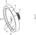
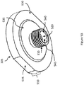
- FIGS. 5A-5B are diagrams of a mounting plate 305 included in the adaptor 105 of FIGS. 2-4 .
- FIG 5A illustrates the mounting plate 305 from an angled, top-down perspective.
- FIG. 5B illustrates the mounting plate 305 from an angled, bottoms-up perspective.
- the mounting plate 305 includes a first surface 505 that is within a recessed portion of the mounting plate 305 and is formed by a collar 510 extending vertically around the periphery of the mounting plate 305 and away from the first surface 505.
- the collar 510 can surround a portion of the accelerometer 110 when the adaptor 105 is coupled to the accelerometer 110 and may provide structural support to maintain the union of the adaptor 105 and the accelerometer 110 during high vibrational forces exerted on the system 100 by the machinery component 120 and/or the machine 115 of FIGS. 1-2 .
- the collar 510 includes a plurality of vertical surfaces 515 arranged around the periphery of the mounting plate 305.
- the vertical surfaces 515 enable use of a tool for securing or removing the adaptor 105 from the attachment element, as well as to secure the adaptor 105 during coupling or removal from the accelerometer 110. In some embodiments there may be 2, 3, 4, 5, or 6 vertical surfaces 515. In some embodiments, the number, shape, and arrangement of the vertical surfaces 515 can depend on the shape of the mounting plate 305 and/or the collar 510.
- the mounting plate 305 includes a plate stud 310 which is configured with a bore 520 extending therethrough.
- the bore 520 incudes a first opening 525 in the first surface 505.
- the first opening 525 allows the screw 315 to pass through the bore 520 and into a threaded portion at the base of the accelerometer 110 in order to secure the accelerometer 110 to the adaptor 105.
- the mounting plate 305 includes a second surface 530 located opposite the first surface 505.
- the plate stud 310 is integrated with the mounting plate 305 at the second surface 530.
- the second surface 530 is a flat surface.
- the second surface 530 can include a raised or elevated portion 535 which may correspond to the overall shape of the mounting plate 305.
- the raised or elevation portion 535 may not correspond to the overall shape of the mounting plate 305.
- the bore 520 of the plate stud 310 includes a second opening 540.
- the second opening 540 allows the screw 315 to be received into the bore 520 for securing the accelerometer 110 to the adaptor 105.
- the second opening 540 can include a recession 545 allowing the screw head 320 to be positioned or recessed within the plate stud 310.
- FIG. 6 is a flowchart illustrating one exemplary embodiment of a method for aligning a triaxial accelerometer to a machinery component using the system 100 of FIGS. 2-3 and the mounting plate 305 as shown in FIGS. 4 , and 5A-5B .
- the adaptor 105 is positioned with respect to a machine 115 comprising a machinery component 120.
- the adaptor 105 excluding the screw 315, can be positioned with respect to the machine 115 by inserting the plate stud 310 of the adaptor 105 into a hole or other receiving mechanism configured within the machine 115.
- the adaptor 105 can be positioned within the machinery 115 with respect to the machinery component 120.
- the adaptor 105 is secured with respect to the machine 115.
- the plate stud 310 may be inserted into a receiving mechanism configured with respect to the machine, such as a threaded bore.
- the adaptor 105 can be secured to the machine 115 by screwing the plate stud 310 into the receiving mechanism and applying a predetermined or specified amount of torque to the mounting plate to secure the adaptor 105 within the receiving mechanism of the machine 115.
- a measurement axis 125 of the machinery component 120 is determined. Based on the configuration and orientation of the machine 115 and/or the machinery component 120, the measurement axis 125 of the machinery component 120 for which vibration data is to be collected can be determined.
- a machinery component 120 oriented horizontally can be determined to have a measurement axis corresponding to an X-axis.
- a machinery component 120 that is oriented vertically can be determined to have a measurement axis corresponding to a Y-axis.
- a machinery component 120 that is oriented orthogonally to X and Y-axes can be determined to have a measurement axis corresponding to a Z-axis.
- an indicator of the measurement axis 125 is applied on the mounting plate 305.
- the indicator will indicate the orientation of the measurement axis 125 on the mounting plate 305.
- the indicator can be applied using a marker pen.
- the indicator can be applied using a sharp object to etch a mark or indicator mark into the mounting plate 305.
- the indicator can be a sticker that can be applied to the mounting plate 305 to denote the orientation of the measurement axis 125.
- the adaptor 305 is removed from the machine. Having applied the indicator of the measurement axis 125 to the mounting plate 305, the orientation of the measurement axis 125 is now defined relative to the mounting plate 305. The indicator can then serve as an alignment aid when coupling the accelerometer 110 to the adaptor 105.
- the adaptor 105 can be removed from the machine 115 by unscrewing the plate stud 310 from the receiving mechanism of the machine 115 or by otherwise decoupling the adaptor 105 from the machine..
- an accelerometer 110 is coupled to the adaptor 105.
- the accelerometer 110 can be coupled to the adaptor 105 by inserting a screw 315 through the second opening 535 of the plate stud 310 into the bore 520 such that the screw 315 can further pass through the first opening 525 and into the accelerometer 110. While the accelerometer 110 is being coupled to the adaptor 105, the reference axis indicator 325 of the accelerometer 110 can be maintained in alignment the measurement axis indicator applied to the mounting plate 305 during operation 640.
- the adaptor 105 including the coupled accelerometer, is secured with respect to the machine 115. Operation 670 is performed in a similar manner as operation 620, however in operation 670, the adaptor 105 is now coupled to the accelerometer and ready for use in collecting and monitoring vibration data associated with the machinery component 120.
- the machinery component 120 can be operated and vibration data can be collected via the accelerometer 110.
- the collected vibration data will now properly correlate to the appropriate measurement axis 125 because of the proper alignment with the reference axis indicator that can be achieved by the system 100 and specifically by the adaptor 105.
- the improved alignment system described herein addresses the technical problem of ensuring alignment of a reference axis of an accelerometer with a measurement axis of a machinery component.
- the problem of properly aligning these two axes can be difficult, time-consuming, and prone to error often requiring multiple attempts and numbers re-installations of the accelerometer in order to determine the proper alignment.
- the exemplary technical effects of the methods, systems, and devices described herein include, by way of non-limiting example, providing an adaptor capable of enabling proper alignment of a reference axis of an accelerometer with a corresponding measurement axis of a machinery component for which vibration data is to be collected.
- the adaptor By providing an adaptor configured to receive an indicator of a measurement axis of the machinery component to be monitored, and aligning that measurement axis indicator with the reference axis indicator of the accelerometer, the adaptor can achieve proper alignment between these two axes in an intuitive, easy to use manner, that produces consistent alignment during a single or repeated installations.
- the adaptor and system described herein reduces the estimation and trial and error previously required to determine such alignment and allows for maintaining the proper alignment over repeated re-installations of the accelerometer.
- Approximating language may be applied to modify any quantitative representation that could permissibly vary without resulting in a change in the basic function to which it is related. Accordingly, a value modified by a term or terms, such as “about,” “approximately,” and “substantially,” are not to be limited to the precise value specified. In at least some instances, the approximating language may correspond to the precision of an instrument for measuring the value.
- range limitations may be combined and/or interchanged, such ranges are identified and include all the sub-ranges contained therein unless context or language indicates otherwise.
Landscapes
- Physics & Mathematics (AREA)
- General Physics & Mathematics (AREA)
- Measurement Of Mechanical Vibrations Or Ultrasonic Waves (AREA)
Abstract
Description
- Accelerometers can be used to monitor vibration that may be occurring with respect to a component of machinery. Triaxial accelerometers can be configured to measure vibration data in three orthogonal directions, often described as the X-axis, Y-axis, and Z-axis. In order to accurately measure vibration data along a desired axis of the machinery component, a reference axis of the accelerometer must be aligned with a corresponding measurement axis of the machinery component so that the vibration data received by accelerometer properly reflects vibration occurring along the desired axis of the machinery component.
- In general, devices, system, and methods are provided for aligning a triaxial accelerometer with respect to a machinery component.
- In one aspect, an adaptor is provided. In one embodiment, the adaptor can include a mounting plate configured to couple an accelerometer to a machinery component. The mounting plate can include a first surface and a second surface. The second surface can be opposite the first surface. The adaptor can also include a plate stud integrated with the mounting plate at the second surface. The adaptor can include a screw. The screw can include a screw head. The screw can be configured to couple the accelerometer to the mounting plate such that a reference axis indicator of the accelerometer is aligned with a measurement axis indicator applied to the mounting plate.
- In another aspect, a system is provided. In one embodiment, the system can include an adaptor. The adaptor can be configured to couple an accelerometer to a machinery component. The adaptor can include a mounting plate. The mounting plate can include a first surface and a second surface. The second surface can be opposite the first surface. The mounting plate can also include a plate stud integrated within the mounting plate at the second surface. The adaptor can include a screw. The screw can include a screw head. The system can also include an accelerometer coupled to the mounting plate via the screw such that a reference axis indicator of the accelerometer is aligned with a measurement axis indicator applied to the mounting plate. The accelerometer can be configured to measure vibration data associated with a machinery component.
- In another aspect, a method for aligning a triaxial accelerometer with respect to a machinery component is provided. In one embodiment, the method can include positioning an adaptor with respect to a machine. The adaptor can include a mounting plate and a screw. The method can also include securing the adaptor with respect to the machine. The method can further include determining a measurement axis of a machinery component of the machine. The method can include applying an indicator of the measurement axis on the mounting plate. The method can also include removing the adaptor from the machine. The method can further include coupling an accelerometer to the adaptor so as to align a reference axis indicator of the accelerometer with the measurement axis indicator on the mounting plate. The method can include securing the adaptor, including the coupled accelerometer, with respect to the machine.
- These and other features will be more readily understood from the following detailed description taken in conjunction with the accompanying drawings, in which:
-
FIG. 1 is a diagram illustrating an exemplary embodiment of a system for aligning an accelerometer with respect to a machinery component; -
FIG. 2 is a diagram illustrating another exemplary embodiment of a system for aligning an accelerometer with respect to a machinery component; -
FIG. 3 is a diagram of an embodiment of the system ofFIG. 2 ; -
FIG. 4 is a diagram of another embodiment of the system ofFIG. 2 ; -
FIGS. 5A-5B are diagrams of a mounting plate included in the adaptor ofFIGS. 2-4 ; and -
FIG. 6 is a flowchart illustrating one exemplary embodiment of a method for aligning an accelerometer to a machinery component using the system ofFIGS. 2-3 . - It is noted that the drawings are not necessarily to scale. The drawings are intended to depict only typical aspects of the subject matter disclosed herein, and therefore should not be considered as limiting the scope of the disclosure.
- Accelerometers, such as triaxial accelerometers, can be mounted to a machinery component to monitor for vibration generated by the machinery component during operation. Triaxial accelerometers can measure vibration data in three orthogonal Cartesian coordinate planes, represented as X, Y, and Z-axes. In order to collect accurate vibration data with respect to any one of these axes, it is important to align a reference axis of the accelerometer with a corresponding axis of the machinery component. For example, to measure vibration data associated with a horizontally-oriented shaft within a compressor or engine, the reference axis of the accelerometer must be aligned with the axis around which the shaft is rotating. Since the shaft is horizontally oriented, it can be determined that the shaft is rotating about the X-axis and thus the measurement axis of the shaft can be determined to be the X-axis. Once the measurement axis has been determined, the accuracy of the collected vibration data will depend on the proper alignment of the reference axis of the accelerometer with the measurement axis of the machinery component.
- Properly aligning the reference axis of the accelerometer with the measurement axis of the machinery component for which vibration data is to be collected can be difficult when the accelerometer is mounted to the machinery component via a single mounting stud because the accelerometer may rotate around the stud causing the reference axis of the accelerometer to become unaligned from the measurement axis of the machinery component. This can be problematic when repeatedly installing and removing accelerometers from the machinery component. Another contributing factor to misalignment between the reference axis of the accelerometer and the measurement axis of the machinery component can be a misalignment between the start of the thread patterns on the mounting stud and the start of the thread patterns within the screw hole of an attachment element or bracket which may be used to mount the accelerometer to the machinery component. The thread patterns of on the mounting stud and the screw hole are not controllable and are not synchronized because they are manufactured by different vendors. As a result, when the accelerometer is tightened to the mounting stud with the required amount of torque, the reference axis of the accelerometer and the measurement axis of the machinery component may not be aligned.
- An improved alignment system can be configured to provide consistent, repeatable alignment between a reference axis of an accelerometer and a measurement axis of a machinery component. The improved alignment system allows a reference axis indicator of the accelerometer to be aligned with a measurement axis indicator applied to the mounting plate. As compared to other alignment systems, the improved alignment system includes a small number of parts offering simple installation and requires no modifications to the accelerometer for installation making single or repeated installations simpler and less prone to installation errors, which can cause vibration data to be inaccurately reported and analyzed. The design of the system provides a low-profile adaptor that enables vibration data to be acquired from machinery components operating at higher frequencies, thus providing more robust performance as compared to other alignment systems.
- An improved alignment system is provided herein including systems, devices, and methods for aligning a reference axis of an accelerometer with a measurement axis of a machinery component. The alignment system can include an adaptor configured to couple an accelerometer to a machinery component. The adaptor can include a mounting plate and a plate stud integrated within the mounting plate to receive a screw to couple the accelerometer to the mounting plate. The mounting plate can be installed with respect to a machinery component being monitored for vibration data and a determination of the desired measurement axis of the machinery component can be made. Based on determining the orientation of the measurement axis of the machinery component, an indicator can be applied to the mounting plate denoting the orientation or position of the measurement axis on the mounting plate. Once applied, the indicator of the measurement axis can be used to align an indicator of the reference axis that is indicated on the accelerometer with the indicator of the measurement axis that has been applied to the mounting plate. The screw can then be inserted through the integrated plate stud and into the accelerometer. As the screw is tightened, the alignment of the measurement axis of machinery component (as indicated by the indicator applied to the mounting plate) can be maintained with respect to the reference axis of the accelerometer (as indicated by the reference axis indicator on the accelerometer). The accelerometer, now coupled to the mounting plate, can be installed with respect to the machinery component thereby securing the accelerometer in a proper alignment with respect to the machinery component being monitored for vibration data.
- Embodiments of systems, devices, and methods for aligning an accelerometer with a machinery component are discussed herein. However, embodiments of the disclosure can be employed for aligning other monitoring devices or sensors to a broad variety of machinery or machinery components without limit.
-
FIG. 1 is a diagram illustrating an exemplary embodiment of asystem 100 for aligning an accelerometer with respect to a machinery component. As shown inFIG. 1 , analignment system 100 can be attached to a piece ofmachinery 115, such as a motor. Themachinery 115 includes amachinery component 120, such as a rotating shaft for which vibration data is to be collected. Thealignment system 100 includes anadaptor 105 and anaccelerometer 110. Theaccelerometer 110 can include a single-axis accelerometer, a dual-axis accelerometer, a triaxial accelerometer, a velocity vibration transducer, or a displacement vibration transducer, or the like. - The
adaptor 105 can be configured to couple theaccelerometer 110 to themachine 115. In some embodiments, theadaptor 105 can be coupled to themachinery 115 directly via an attachment element. In the case of a triaxial accelerometer, theaccelerometer 110 can be configured to collect and generate vibration data in any of three individual axes, such as the X, Y, and Z-axes. Themachinery component 120 can be operating or otherwise moving with respect to one particular axis. - As shown in
FIG. 1 , themotor 115 includes arotating shaft 120 which is rotating with respect to a horizontal axis, or the X-axis. The axis of themachinery component 120 for which the vibration data is to be collected can be referred to as the measurement axis. As shown inFIG. 1 , the measurement axis of therotating shaft 120 is a horizontal or theX-axis 125. Thus therotating shaft 120 has ameasurement axis 125 that corresponds to a horizontal or X-axis. In order to accurately and efficiently collect the vibration data, it is useful to ensure that ameasurement axis 125 of themachinery component 120 is aligned with areference axis 130 of thetriaxial accelerometer 110. In this way, the collected vibration data is accurate with respect to themeasurement axis 125 for which it was collected. Properly aligning thereference axis 130 of theaccelerometer 110 with themeasurement axis 125 of themachinery component 120 can avoid the need for subsequent post-processing of the collected vibration data that may be required to correctly associate the axial orientation of the collected vibration data with the axial orientation of the machinery component generating the vibration data. -
FIG. 2 is a diagram illustrating another exemplary embodiment of asystem 100 for aligning an accelerometer with respect to a machinery component. As shown inFIG. 2 , thealignment system 100 includes anadaptor 105 and anaccelerometer 110. Thealignment system 100 is mounted to amachine 115. The alignment system is configured to monitor vibration data generated by amachinery component 120. Following the preceding example, themachinery 115 can be a motor and can include anoperable component 120, such as a rotating shaft, for which vibration data is to be collected using thesystem 100. Thecomponent 120 can be rotating with respect to ameasurement axis 125. - To aid discussion of the
system 100, a reference axis indicator is provided in the lower right portion of the figure. The X-axis can be considered to be associated with a plane that traversesFIG. 2 horizontally, while the Y-axis can be considered to be associated with a plane extending into and out of the diagram shown inFIG. 2 . The Z-axis can be considered to be associated with a plane that traversesFIG. 2 vertically. - As shown in
FIG. 2 , themeasurement axis 125 of themachinery component 125 corresponds to the X-axis. Theaccelerometer 110 can include one or more reference axes, such as a reference axis oriented with respect to the X-axis. Thereference axis 130 should be aligned with and oriented relative to themeasurement axis 125 in order to collect accurate measurements of the vibration generated by themachinery component 120. As shown inFIG. 2 , thesystem 100 has been installed to properly align thereference axis 130 of theaccelerometer 110 with themeasurement axis 125 that has been determined for themachinery component 120. -
FIG. 3 is a diagram of an exemplary embodiment of thesystem 100 ofFIG. 2 . As shown inFIG. 3 , theadaptor 105 can be coupled to theaccelerometer 110. - To aid discussion of the
system 100 shown inFIG. 3 , a reference axis indicator is provided in the lower right portion of the figure. The X-axis can be considered to be associated with a plane extending into and out of the diagram shown inFIG. 3 orthogonally to the Z and Y-axes that traverseFIG. 3 , while the Y-axis can be considered to be associated with a plane that traversesFIG. 3 vertically. The Z-axis can be considered to be associated with a plane that traversesFIG. 3 horizontally. - As shown in
FIG. 3 , theadaptor 105 includes a mountingplate 305 and aplate stud 310 that is integrated within the mountingplate 305. The mountingplate 305 can be configured to receive and couple to theaccelerometer 110 and can be shaped as a circle as shown inFIG. 3 . In some embodiments, the mountingplate 305 can be shaped as an oval, a rectangle, a square, a triangle, a polygon, or a parallelogram, or the like. In some embodiments, the shape and dimensionality of the mountingplate 305 can correspond to a shape and dimensionality of theaccelerometer 110. Theplate stud 310 can be a threaded stud extending away from the mountingplate 305. The outer surface of theplate stud 310 can be threaded in order to secure theadaptor 105 to themachinery 115 and/or to amachinery component 120. In some embodiments, outer diameter of the plate stud is 1/2" and can include a 20 threads per in pitch pattern. In some embodiments, the outer diameter of the plate stud is 3/8" and can include a 24 threads per in pitch pattern. In some embodiments, theplate stud 310 can include a smooth bore through which ascrew 315 can pass in order to secure theaccelerometer 110 to secure theaccelerometer 110 to theadaptor 105. Theaccelerometer 110 is secured to theadaptor 105 by tightening thescrew 315 such that thescrew head 320 is seated against the end of theplate stud 310 opposite theaccelerometer 110. In some embodiments, thescrew 315 can be a metric screw with a nominal outer diameter of 4mm or 6 mm, such as an "M4" or "M6" screw as designated by the International Organization for Standards (ISO). - As further shown in
FIG. 3 , theaccelerometer 110 includes areference axis indicator 325 and a referenceaxis indicator legend 330. Thereference axis indicator 325 can be a mark or etching applied to theaccelerometer 110 to indicate a particular, designated reference axis of theaccelerometer 110. As shown inFIG. 3 , based on the orientation of the Z and Y axes provided in the referenceaxis indicator legend 330, it can be determined that thereference axis indicator 325 indicates that the orientation of the reference axis corresponds to an X-axis reference axis, such as theX-axis reference axis 130 shownFIG. 2 . In some embodiments, thereference axis indicator 325 can correspond to a Y-axis reference axis or a Z-axis reference axis. Having determined the orientation of the X-axis reference axis, the referenceaxis indicator legend 330 can assist in determining the orientation of the other reference axes of theaccelerometer 110. As shown inFIG. 3 , the Z-axis reference axis 335 can be further determined. The Y-axis reference axis would appropriately be oriented orthogonally to the X and Z axes. Thereference axis indicator 325 can be used to align theadaptor 105 with theaccelerometer 110. In this way, as shown inFIG. 2 , thereference axis 130 of theaccelerometer 110 is aligned with themeasurement axis 125 of themachinery component 120. -
FIG. 4 is a diagram of another exemplary embodiment of thesystem 100 ofFIGS. 2 and3 . As shown inFIG. 4 , theadaptor 105 can further include a threadedcoupling 405. The threadedcoupling 405 can be used in embodiments when theplate stud 310 is configured as a 3/8"-24 sized stud and an M4sized screw 315 is used. The threadedcoupling 405 can include an inner thread pitch pattern that is associated with an M4sized screw 315 and an outer thread pitch pattern that is associated with an M6sized screw 315. In this way, the threadedcoupling 405 can be used to receive an M4sized screw 315 within theplate stud 310 so as to couple anaccelerometer 110 configured to receive an M6sized screw 315 to the mountingplate 305. -
FIGS. 5A-5B are diagrams of a mountingplate 305 included in theadaptor 105 ofFIGS. 2-4 .FIG 5A illustrates the mountingplate 305 from an angled, top-down perspective.FIG. 5B illustrates the mountingplate 305 from an angled, bottoms-up perspective. - As shown in
FIG. 5A , the mountingplate 305 includes afirst surface 505 that is within a recessed portion of the mountingplate 305 and is formed by acollar 510 extending vertically around the periphery of the mountingplate 305 and away from thefirst surface 505. Thecollar 510 can surround a portion of theaccelerometer 110 when theadaptor 105 is coupled to theaccelerometer 110 and may provide structural support to maintain the union of theadaptor 105 and theaccelerometer 110 during high vibrational forces exerted on thesystem 100 by themachinery component 120 and/or themachine 115 ofFIGS. 1-2 . Thecollar 510 includes a plurality ofvertical surfaces 515 arranged around the periphery of the mountingplate 305. Thevertical surfaces 515 enable use of a tool for securing or removing theadaptor 105 from the attachment element, as well as to secure theadaptor 105 during coupling or removal from theaccelerometer 110. In some embodiments there may be 2, 3, 4, 5, or 6vertical surfaces 515. In some embodiments, the number, shape, and arrangement of thevertical surfaces 515 can depend on the shape of the mountingplate 305 and/or thecollar 510. - As further shown in
FIG. 5A , the mountingplate 305 includes aplate stud 310 which is configured with abore 520 extending therethrough. Thebore 520 incudes afirst opening 525 in thefirst surface 505. Thefirst opening 525 allows thescrew 315 to pass through thebore 520 and into a threaded portion at the base of theaccelerometer 110 in order to secure theaccelerometer 110 to theadaptor 105. - As shown in
FIG. 5B , the mountingplate 305 includes asecond surface 530 located opposite thefirst surface 505. Theplate stud 310 is integrated with the mountingplate 305 at thesecond surface 530. In some embodiments, thesecond surface 530 is a flat surface. In other embodiments, thesecond surface 530 can include a raised orelevated portion 535 which may correspond to the overall shape of the mountingplate 305. In some embodiments, the raised orelevation portion 535 may not correspond to the overall shape of the mountingplate 305. Thebore 520 of theplate stud 310 includes asecond opening 540. Thesecond opening 540 allows thescrew 315 to be received into thebore 520 for securing theaccelerometer 110 to theadaptor 105. In some embodiments thesecond opening 540 can include arecession 545 allowing thescrew head 320 to be positioned or recessed within theplate stud 310. -
FIG. 6 is a flowchart illustrating one exemplary embodiment of a method for aligning a triaxial accelerometer to a machinery component using thesystem 100 ofFIGS. 2-3 and the mountingplate 305 as shown inFIGS. 4 , and5A-5B . - In
operation 610, theadaptor 105 is positioned with respect to amachine 115 comprising amachinery component 120. Theadaptor 105, excluding thescrew 315, can be positioned with respect to themachine 115 by inserting theplate stud 310 of theadaptor 105 into a hole or other receiving mechanism configured within themachine 115. In some embodiments, theadaptor 105 can be positioned within themachinery 115 with respect to themachinery component 120. - In
operation 620, theadaptor 105 is secured with respect to themachine 115. Theplate stud 310 may be inserted into a receiving mechanism configured with respect to the machine, such as a threaded bore. In this example, theadaptor 105 can be secured to themachine 115 by screwing theplate stud 310 into the receiving mechanism and applying a predetermined or specified amount of torque to the mounting plate to secure theadaptor 105 within the receiving mechanism of themachine 115. - In
operation 630, ameasurement axis 125 of themachinery component 120 is determined. Based on the configuration and orientation of themachine 115 and/or themachinery component 120, themeasurement axis 125 of themachinery component 120 for which vibration data is to be collected can be determined. Amachinery component 120 oriented horizontally can be determined to have a measurement axis corresponding to an X-axis. Amachinery component 120 that is oriented vertically can be determined to have a measurement axis corresponding to a Y-axis. Amachinery component 120 that is oriented orthogonally to X and Y-axes can be determined to have a measurement axis corresponding to a Z-axis. - In
operation 640, an indicator of themeasurement axis 125 is applied on the mountingplate 305. The indicator will indicate the orientation of themeasurement axis 125 on the mountingplate 305. In some embodiments, the indicator can be applied using a marker pen. In some embodiments, the indicator can be applied using a sharp object to etch a mark or indicator mark into the mountingplate 305. In some embodiments, the indicator can be a sticker that can be applied to the mountingplate 305 to denote the orientation of themeasurement axis 125. - In
operation 650, theadaptor 305 is removed from the machine. Having applied the indicator of themeasurement axis 125 to the mountingplate 305, the orientation of themeasurement axis 125 is now defined relative to the mountingplate 305. The indicator can then serve as an alignment aid when coupling theaccelerometer 110 to theadaptor 105. Theadaptor 105 can be removed from themachine 115 by unscrewing theplate stud 310 from the receiving mechanism of themachine 115 or by otherwise decoupling theadaptor 105 from the machine.. - In
operation 660, anaccelerometer 110 is coupled to theadaptor 105. Theaccelerometer 110 can be coupled to theadaptor 105 by inserting ascrew 315 through thesecond opening 535 of theplate stud 310 into thebore 520 such that thescrew 315 can further pass through thefirst opening 525 and into theaccelerometer 110. While theaccelerometer 110 is being coupled to theadaptor 105, thereference axis indicator 325 of theaccelerometer 110 can be maintained in alignment the measurement axis indicator applied to the mountingplate 305 duringoperation 640. In this way, as thescrew 315 is tightened to couple theaccelerometer 110 to theadaptor 105, alignment between thereference axis indicator 325 and the measurement axis indicator on the mountingplate 305 can be achieved to ensure the reference axis of theaccelerometer 110 is properly aligned with themeasurement axis 125 of themachinery component 120. - In
operation 670, theadaptor 105, including the coupled accelerometer, is secured with respect to themachine 115.Operation 670 is performed in a similar manner asoperation 620, however inoperation 670, theadaptor 105 is now coupled to the accelerometer and ready for use in collecting and monitoring vibration data associated with themachinery component 120. - In
operation 680, themachinery component 120 can be operated and vibration data can be collected via theaccelerometer 110. The collected vibration data will now properly correlate to theappropriate measurement axis 125 because of the proper alignment with the reference axis indicator that can be achieved by thesystem 100 and specifically by theadaptor 105. - The improved alignment system described herein addresses the technical problem of ensuring alignment of a reference axis of an accelerometer with a measurement axis of a machinery component. The problem of properly aligning these two axes can be difficult, time-consuming, and prone to error often requiring multiple attempts and numbers re-installations of the accelerometer in order to determine the proper alignment. The exemplary technical effects of the methods, systems, and devices described herein include, by way of non-limiting example, providing an adaptor capable of enabling proper alignment of a reference axis of an accelerometer with a corresponding measurement axis of a machinery component for which vibration data is to be collected. By providing an adaptor configured to receive an indicator of a measurement axis of the machinery component to be monitored, and aligning that measurement axis indicator with the reference axis indicator of the accelerometer, the adaptor can achieve proper alignment between these two axes in an intuitive, easy to use manner, that produces consistent alignment during a single or repeated installations. The adaptor and system described herein reduces the estimation and trial and error previously required to determine such alignment and allows for maintaining the proper alignment over repeated re-installations of the accelerometer.
- Certain exemplary embodiments have been described to provide an overall understanding of the principles of the structure, function, manufacture, and use of the systems, devices, and methods disclosed herein. One or more examples of these embodiments have been illustrated in the accompanying drawings. Those skilled in the art will understand that the systems, devices, and methods specifically described herein and illustrated in the accompanying drawings are non-limiting exemplary embodiments and that the scope of the present invention is defined solely by the claims. The features illustrated or described in connection with one exemplary embodiment may be combined with the features of other embodiments. Such modifications and variations are intended to be included within the scope of the present invention. Further, in the present disclosure, like-named components of the embodiments generally have similar features, and thus within a particular embodiment each feature of each like-named component is not necessarily fully elaborated upon.
- Approximating language, as used herein throughout the specification and claims, may be applied to modify any quantitative representation that could permissibly vary without resulting in a change in the basic function to which it is related. Accordingly, a value modified by a term or terms, such as "about," "approximately," and "substantially," are not to be limited to the precise value specified. In at least some instances, the approximating language may correspond to the precision of an instrument for measuring the value. Here and throughout the specification and claims, range limitations may be combined and/or interchanged, such ranges are identified and include all the sub-ranges contained therein unless context or language indicates otherwise.
- One skilled in the art will appreciate further features and advantages of the invention based on the above-described embodiments. Accordingly, the present application is not to be limited by what has been particularly shown and described, except as indicated by the appended claims. All publications and references cited herein are expressly incorporated by reference in their entirety.
Claims (20)
- An adaptor comprising:a mounting plate configured to couple an accelerometer to a machinery component, the mounting plate including a first surface and a second surface, the second surface opposite the first surface, and a plate stud integrated with the mounting plate at the second surface; anda screw, including a screw head, the screw configured to couple the accelerometer to the mounting plate such that a reference axis indicator of the accelerometer is aligned with a measurement axis indicator applied to the mounting plate.
- The adaptor of claim 1, wherein the mounting plate is shaped as a circle, an oval, a rectangle, a square, a triangle, a polygon, or a parallelogram.
- The adaptor of claim 1, further comprising a collar arranged with respect to a periphery of the mounting plate and extending vertically away from the first surface of the mounting plate at which the accelerometer is coupled to the mounting plate so as to surround a portion of the accelerometer.
- The adaptor of claim 3, wherein the collar includes a plurality of vertical surfaces arranged around the periphery of the mounting plate.
- The adaptor of claim 1, wherein the plate stud includes a first screw thread configuration corresponding to a first outer diameter of the plate stud or a second screw thread configuration corresponding a second outer diameter of the plate stud.
- The adaptor of claim 1, wherein the plate stud extends away from the second surface of the mounting plate and includes a bore extending through the plate stud, the bore including a first opening in the first surface of the mounting plate and a second opening opposite the second surface of the mounting plate, the bore allowing the screw to pass through the plate stud and the mounting plate to couple the accelerometer to the mounting plate.
- The adaptor of claim 6, wherein the second opening of the bore is configured to receive the screw head within a recess formed within the second opening of the bore or to receive the screw head such that the screw head is directly interfaced with the second opening of the plate stud.
- A system comprising:an adaptor configured to couple an accelerometer to a machinery component, the adaptor including,a mounting plate including a first surface and a second surface, the second surface opposite the first surface, and a plate stud integrated with the mounting plate at the second surface; anda screw, including a screw head; andan accelerometer coupled to the mounting plate via the screw such that a reference axis indicator of the accelerometer is aligned with a measurement axis indicator applied to the mounting plate, the accelerometer configured to measure vibration data associated with a machinery component.
- The system of claim 8, wherein the mounting plate is shaped as a circle, an oval, a rectangle, a square, a triangle, a polygon, or a parallelogram.
- The system of claim 8, further comprising a collar arranged with respect to a periphery of the mounting plate and extending vertically away from the first surface of the mounting plate at which the accelerometer is coupled to the mounting plate so as to surround a portion of the accelerometer.
- The system of claim 10, wherein the collar includes a plurality of vertical surfaces arranged around the periphery of the mounting plate.
- The system of claim 8, wherein the plate stud includes a first screw thread configuration corresponding to a first outer diameter of the plate stud or a second screw thread configuration corresponding a second outer diameter of the plate stud.
- The system of claim 8, wherein the plate stud extends away from the second surface of the mounting plate and includes a bore extending through the plate stud, the bore including a first opening in the first surface of the mounting plate and a second opening opposite the second surface of the mounting plate, the bore allowing the screw to pass through the plate stud and the mounting plate to couple the accelerometer to the mounting plate.
- The system of claim 13, wherein the second opening of the bore is configured to receive the screw head within a recess formed within the second opening of the bore or to receive the screw head such that the screw head is directly interfaced with the second opening of the plate stud.
- A method comprising:positioning an adaptor, including a mounting plate and a screw, with respect to a machine;securing the adaptor with respect to the machine;determining a measurement axis of a machinery component of the machine;applying an indicator of the measurement axis on the mounting plate;removing the adaptor from the machine;coupling an accelerometer to the adaptor so as to align a reference axis indicator of the accelerometer with the measurement axis indicator on the mounting plate; andsecuring the adaptor, including the coupled accelerometer, with respect to the machine.
- The method of claim 15, wherein securing the adaptor with respect to the machine includes applying a predetermined amount of torque to the mounting plate.
- The method of claim 15, wherein the accelerometer includes a single-axis accelerometer, a dual-axis accelerometer, a triaxial accelerometer, a velocity vibration transducer, or a displacement vibration transducer.
- The method of claim 15, wherein applying a measurement axis indicator includes applying the measurement axis indicator on the mounting plate with a marker or sharp object, the measurement axis indicator corresponding to the determined measurement axis of the machinery component.
- The method of claim 15, further comprising operating the machinery component and collecting vibration data via the accelerometer.
- The method of claim 15, wherein the accelerometer is coupled within the adaptor by inserting the screw through a plate stud integrated with the mounting plate and tightening the screw in the accelerometer with a predetermine amount of torque.
Applications Claiming Priority (2)
| Application Number | Priority Date | Filing Date | Title |
|---|---|---|---|
| US201962851748P | 2019-05-23 | 2019-05-23 | |
| US16/867,670 US11385253B2 (en) | 2019-05-23 | 2020-05-06 | Triaxial accelerometer mounting adapter |
Publications (2)
| Publication Number | Publication Date |
|---|---|
| EP3742177A1 true EP3742177A1 (en) | 2020-11-25 |
| EP3742177B1 EP3742177B1 (en) | 2023-03-22 |
Family
ID=70802727
Family Applications (1)
| Application Number | Title | Priority Date | Filing Date |
|---|---|---|---|
| EP20175869.5A Active EP3742177B1 (en) | 2019-05-23 | 2020-05-20 | Accelerometer mounting adaptor, accelerometer mounting system and accelerometer mounting method |
Country Status (3)
| Country | Link |
|---|---|
| US (1) | US11385253B2 (en) |
| EP (1) | EP3742177B1 (en) |
| DK (1) | DK3742177T3 (en) |
Citations (4)
| Publication number | Priority date | Publication date | Assignee | Title |
|---|---|---|---|---|
| US4823602A (en) * | 1987-06-19 | 1989-04-25 | The Dow Chemical Company | Accelerometer mounting device |
| US20100092117A1 (en) * | 2007-06-19 | 2010-04-15 | Ntn Corporation | Wheel Bearing Apparatus Incorporated With A Wheel Speed Detecting Apparatus |
| GB2471526A (en) * | 2009-07-03 | 2011-01-05 | Monitran Ltd | Mounting assembly for a sensor |
| US20140117059A1 (en) * | 2012-10-26 | 2014-05-01 | Azima Holdings, Inc. | Sensor Mounting Apparatus and Methods of Using Same |
Family Cites Families (1)
| Publication number | Priority date | Publication date | Assignee | Title |
|---|---|---|---|---|
| FR3027975B1 (en) * | 2014-10-31 | 2017-05-05 | 01Db-Metravib | DEVICE AND METHOD FOR MOUNTING AND ORIENTING A SENSOR ON A SUPPORT |
-
2020
- 2020-05-06 US US16/867,670 patent/US11385253B2/en active Active
- 2020-05-20 EP EP20175869.5A patent/EP3742177B1/en active Active
- 2020-05-20 DK DK20175869.5T patent/DK3742177T3/en active
Patent Citations (4)
| Publication number | Priority date | Publication date | Assignee | Title |
|---|---|---|---|---|
| US4823602A (en) * | 1987-06-19 | 1989-04-25 | The Dow Chemical Company | Accelerometer mounting device |
| US20100092117A1 (en) * | 2007-06-19 | 2010-04-15 | Ntn Corporation | Wheel Bearing Apparatus Incorporated With A Wheel Speed Detecting Apparatus |
| GB2471526A (en) * | 2009-07-03 | 2011-01-05 | Monitran Ltd | Mounting assembly for a sensor |
| US20140117059A1 (en) * | 2012-10-26 | 2014-05-01 | Azima Holdings, Inc. | Sensor Mounting Apparatus and Methods of Using Same |
Also Published As
| Publication number | Publication date |
|---|---|
| EP3742177B1 (en) | 2023-03-22 |
| US11385253B2 (en) | 2022-07-12 |
| US20200371127A1 (en) | 2020-11-26 |
| DK3742177T3 (en) | 2023-04-24 |
Similar Documents
| Publication | Publication Date | Title |
|---|---|---|
| US11781941B2 (en) | Multi-degree-of-freedom impedance fixture for automated frequency response function measurements | |
| JP6399973B2 (en) | Method for adjusting plating apparatus and measuring apparatus | |
| EP4012334B1 (en) | Surveying pole and secondary sensor unit having toroidal form | |
| CN109631828B (en) | Method for detecting the angle between coordinate axes of adjacent spatial coordinate systems based on cube prism | |
| US9212884B2 (en) | Measuring device | |
| US10866256B2 (en) | Universal sensor mount | |
| US11385253B2 (en) | Triaxial accelerometer mounting adapter | |
| WO2002097362A1 (en) | Photogrammetry targets | |
| US20120017671A1 (en) | Test gauge | |
| JP3204906U (en) | Angle measurement tool | |
| CN108709482B (en) | Auto parts space vertical hole system distance vertical measuring tool | |
| JP4841142B2 (en) | Method and system for screw tolerance inspection | |
| JP5437693B2 (en) | Automatic correction value measurement method for spindle or attachment spindle | |
| JP2010181198A (en) | Instrument and method for measuring mounting position of support part | |
| CN220153436U (en) | Comprehensive detection tool for motor iron core | |
| US8806943B2 (en) | Golf shaft assembly oscillation analyzer | |
| EP4563935A1 (en) | Method for determining information about one or more depressions in a part | |
| CN220533709U (en) | Measuring tool for measuring tungsten ring groove depth | |
| CN117542789B (en) | Perpendicularity adjusting device and perpendicularity adjusting method | |
| US2694926A (en) | Cord tension indicator | |
| CN117516335A (en) | Roundness measuring method, tool and combined structure of large cylinder or cylindrical structure | |
| EP3885696B1 (en) | Touching detection device | |
| JP3069225B2 (en) | Measuring object mounting jig for inner and outer measuring devices | |
| EP2912283B1 (en) | An alignment device for a turbomachine component and turbomachine including such device | |
| KR20170053788A (en) | Screw fastening apparatus and holder |
Legal Events
| Date | Code | Title | Description |
|---|---|---|---|
| PUAI | Public reference made under article 153(3) epc to a published international application that has entered the european phase |
Free format text: ORIGINAL CODE: 0009012 |
|
| STAA | Information on the status of an ep patent application or granted ep patent |
Free format text: STATUS: REQUEST FOR EXAMINATION WAS MADE |
|
| 17P | Request for examination filed |
Effective date: 20200520 |
|
| AK | Designated contracting states |
Kind code of ref document: A1 Designated state(s): AL AT BE BG CH CY CZ DE DK EE ES FI FR GB GR HR HU IE IS IT LI LT LU LV MC MK MT NL NO PL PT RO RS SE SI SK SM TR |
|
| AX | Request for extension of the european patent |
Extension state: BA ME |
|
| GRAP | Despatch of communication of intention to grant a patent |
Free format text: ORIGINAL CODE: EPIDOSNIGR1 |
|
| STAA | Information on the status of an ep patent application or granted ep patent |
Free format text: STATUS: GRANT OF PATENT IS INTENDED |
|
| INTG | Intention to grant announced |
Effective date: 20221124 |
|
| GRAS | Grant fee paid |
Free format text: ORIGINAL CODE: EPIDOSNIGR3 |
|
| GRAA | (expected) grant |
Free format text: ORIGINAL CODE: 0009210 |
|
| STAA | Information on the status of an ep patent application or granted ep patent |
Free format text: STATUS: THE PATENT HAS BEEN GRANTED |
|
| AK | Designated contracting states |
Kind code of ref document: B1 Designated state(s): AL AT BE BG CH CY CZ DE DK EE ES FI FR GB GR HR HU IE IS IT LI LT LU LV MC MK MT NL NO PL PT RO RS SE SI SK SM TR |
|
| REG | Reference to a national code |
Ref country code: GB Ref legal event code: FG4D |
|
| REG | Reference to a national code |
Ref country code: CH Ref legal event code: EP |
|
| REG | Reference to a national code |
Ref country code: IE Ref legal event code: FG4D |
|
| REG | Reference to a national code |
Ref country code: DE Ref legal event code: R096 Ref document number: 602020008953 Country of ref document: DE |
|
| REG | Reference to a national code |
Ref country code: AT Ref legal event code: REF Ref document number: 1555619 Country of ref document: AT Kind code of ref document: T Effective date: 20230415 |
|
| REG | Reference to a national code |
Ref country code: DK Ref legal event code: T3 Effective date: 20230417 |
|
| P01 | Opt-out of the competence of the unified patent court (upc) registered |
Effective date: 20230526 |
|
| REG | Reference to a national code |
Ref country code: LT Ref legal event code: MG9D |
|
| REG | Reference to a national code |
Ref country code: NL Ref legal event code: MP Effective date: 20230322 |
|
| PG25 | Lapsed in a contracting state [announced via postgrant information from national office to epo] |
Ref country code: RS Free format text: LAPSE BECAUSE OF FAILURE TO SUBMIT A TRANSLATION OF THE DESCRIPTION OR TO PAY THE FEE WITHIN THE PRESCRIBED TIME-LIMIT Effective date: 20230322 Ref country code: NO Free format text: LAPSE BECAUSE OF FAILURE TO SUBMIT A TRANSLATION OF THE DESCRIPTION OR TO PAY THE FEE WITHIN THE PRESCRIBED TIME-LIMIT Effective date: 20230622 Ref country code: LV Free format text: LAPSE BECAUSE OF FAILURE TO SUBMIT A TRANSLATION OF THE DESCRIPTION OR TO PAY THE FEE WITHIN THE PRESCRIBED TIME-LIMIT Effective date: 20230322 Ref country code: LT Free format text: LAPSE BECAUSE OF FAILURE TO SUBMIT A TRANSLATION OF THE DESCRIPTION OR TO PAY THE FEE WITHIN THE PRESCRIBED TIME-LIMIT Effective date: 20230322 Ref country code: HR Free format text: LAPSE BECAUSE OF FAILURE TO SUBMIT A TRANSLATION OF THE DESCRIPTION OR TO PAY THE FEE WITHIN THE PRESCRIBED TIME-LIMIT Effective date: 20230322 |
|
| REG | Reference to a national code |
Ref country code: AT Ref legal event code: MK05 Ref document number: 1555619 Country of ref document: AT Kind code of ref document: T Effective date: 20230322 |
|
| PG25 | Lapsed in a contracting state [announced via postgrant information from national office to epo] |
Ref country code: SE Free format text: LAPSE BECAUSE OF FAILURE TO SUBMIT A TRANSLATION OF THE DESCRIPTION OR TO PAY THE FEE WITHIN THE PRESCRIBED TIME-LIMIT Effective date: 20230322 Ref country code: NL Free format text: LAPSE BECAUSE OF FAILURE TO SUBMIT A TRANSLATION OF THE DESCRIPTION OR TO PAY THE FEE WITHIN THE PRESCRIBED TIME-LIMIT Effective date: 20230322 Ref country code: GR Free format text: LAPSE BECAUSE OF FAILURE TO SUBMIT A TRANSLATION OF THE DESCRIPTION OR TO PAY THE FEE WITHIN THE PRESCRIBED TIME-LIMIT Effective date: 20230623 Ref country code: FI Free format text: LAPSE BECAUSE OF FAILURE TO SUBMIT A TRANSLATION OF THE DESCRIPTION OR TO PAY THE FEE WITHIN THE PRESCRIBED TIME-LIMIT Effective date: 20230322 |
|
| PG25 | Lapsed in a contracting state [announced via postgrant information from national office to epo] |
Ref country code: SM Free format text: LAPSE BECAUSE OF FAILURE TO SUBMIT A TRANSLATION OF THE DESCRIPTION OR TO PAY THE FEE WITHIN THE PRESCRIBED TIME-LIMIT Effective date: 20230322 Ref country code: RO Free format text: LAPSE BECAUSE OF FAILURE TO SUBMIT A TRANSLATION OF THE DESCRIPTION OR TO PAY THE FEE WITHIN THE PRESCRIBED TIME-LIMIT Effective date: 20230322 Ref country code: PT Free format text: LAPSE BECAUSE OF FAILURE TO SUBMIT A TRANSLATION OF THE DESCRIPTION OR TO PAY THE FEE WITHIN THE PRESCRIBED TIME-LIMIT Effective date: 20230724 Ref country code: ES Free format text: LAPSE BECAUSE OF FAILURE TO SUBMIT A TRANSLATION OF THE DESCRIPTION OR TO PAY THE FEE WITHIN THE PRESCRIBED TIME-LIMIT Effective date: 20230322 Ref country code: EE Free format text: LAPSE BECAUSE OF FAILURE TO SUBMIT A TRANSLATION OF THE DESCRIPTION OR TO PAY THE FEE WITHIN THE PRESCRIBED TIME-LIMIT Effective date: 20230322 Ref country code: AT Free format text: LAPSE BECAUSE OF FAILURE TO SUBMIT A TRANSLATION OF THE DESCRIPTION OR TO PAY THE FEE WITHIN THE PRESCRIBED TIME-LIMIT Effective date: 20230322 |
|
| PG25 | Lapsed in a contracting state [announced via postgrant information from national office to epo] |
Ref country code: SK Free format text: LAPSE BECAUSE OF FAILURE TO SUBMIT A TRANSLATION OF THE DESCRIPTION OR TO PAY THE FEE WITHIN THE PRESCRIBED TIME-LIMIT Effective date: 20230322 Ref country code: PL Free format text: LAPSE BECAUSE OF FAILURE TO SUBMIT A TRANSLATION OF THE DESCRIPTION OR TO PAY THE FEE WITHIN THE PRESCRIBED TIME-LIMIT Effective date: 20230322 Ref country code: IS Free format text: LAPSE BECAUSE OF FAILURE TO SUBMIT A TRANSLATION OF THE DESCRIPTION OR TO PAY THE FEE WITHIN THE PRESCRIBED TIME-LIMIT Effective date: 20230722 |
|
| REG | Reference to a national code |
Ref country code: DE Ref legal event code: R097 Ref document number: 602020008953 Country of ref document: DE |
|
| PG25 | Lapsed in a contracting state [announced via postgrant information from national office to epo] |
Ref country code: MC Free format text: LAPSE BECAUSE OF FAILURE TO SUBMIT A TRANSLATION OF THE DESCRIPTION OR TO PAY THE FEE WITHIN THE PRESCRIBED TIME-LIMIT Effective date: 20230322 |
|
| PLBE | No opposition filed within time limit |
Free format text: ORIGINAL CODE: 0009261 |
|
| STAA | Information on the status of an ep patent application or granted ep patent |
Free format text: STATUS: NO OPPOSITION FILED WITHIN TIME LIMIT |
|
| REG | Reference to a national code |
Ref country code: BE Ref legal event code: MM Effective date: 20230531 |
|
| PG25 | Lapsed in a contracting state [announced via postgrant information from national office to epo] |
Ref country code: SI Free format text: LAPSE BECAUSE OF FAILURE TO SUBMIT A TRANSLATION OF THE DESCRIPTION OR TO PAY THE FEE WITHIN THE PRESCRIBED TIME-LIMIT Effective date: 20230322 Ref country code: MC Free format text: LAPSE BECAUSE OF FAILURE TO SUBMIT A TRANSLATION OF THE DESCRIPTION OR TO PAY THE FEE WITHIN THE PRESCRIBED TIME-LIMIT Effective date: 20230322 Ref country code: LU Free format text: LAPSE BECAUSE OF NON-PAYMENT OF DUE FEES Effective date: 20230520 Ref country code: CZ Free format text: LAPSE BECAUSE OF FAILURE TO SUBMIT A TRANSLATION OF THE DESCRIPTION OR TO PAY THE FEE WITHIN THE PRESCRIBED TIME-LIMIT Effective date: 20230322 |
|
| 26N | No opposition filed |
Effective date: 20240102 |
|
| REG | Reference to a national code |
Ref country code: IE Ref legal event code: MM4A |
|
| PG25 | Lapsed in a contracting state [announced via postgrant information from national office to epo] |
Ref country code: IE Free format text: LAPSE BECAUSE OF NON-PAYMENT OF DUE FEES Effective date: 20230520 |
|
| PG25 | Lapsed in a contracting state [announced via postgrant information from national office to epo] |
Ref country code: IE Free format text: LAPSE BECAUSE OF NON-PAYMENT OF DUE FEES Effective date: 20230520 |
|
| PG25 | Lapsed in a contracting state [announced via postgrant information from national office to epo] |
Ref country code: IT Free format text: LAPSE BECAUSE OF FAILURE TO SUBMIT A TRANSLATION OF THE DESCRIPTION OR TO PAY THE FEE WITHIN THE PRESCRIBED TIME-LIMIT Effective date: 20230322 Ref country code: BE Free format text: LAPSE BECAUSE OF NON-PAYMENT OF DUE FEES Effective date: 20230531 |
|
| PG25 | Lapsed in a contracting state [announced via postgrant information from national office to epo] |
Ref country code: BG Free format text: LAPSE BECAUSE OF FAILURE TO SUBMIT A TRANSLATION OF THE DESCRIPTION OR TO PAY THE FEE WITHIN THE PRESCRIBED TIME-LIMIT Effective date: 20230322 |
|
| PG25 | Lapsed in a contracting state [announced via postgrant information from national office to epo] |
Ref country code: BG Free format text: LAPSE BECAUSE OF FAILURE TO SUBMIT A TRANSLATION OF THE DESCRIPTION OR TO PAY THE FEE WITHIN THE PRESCRIBED TIME-LIMIT Effective date: 20230322 |
|
| PGFP | Annual fee paid to national office [announced via postgrant information from national office to epo] |
Ref country code: DE Payment date: 20250423 Year of fee payment: 6 |
|
| PGFP | Annual fee paid to national office [announced via postgrant information from national office to epo] |
Ref country code: GB Payment date: 20250423 Year of fee payment: 6 Ref country code: DK Payment date: 20250423 Year of fee payment: 6 |
|
| PGFP | Annual fee paid to national office [announced via postgrant information from national office to epo] |
Ref country code: FR Payment date: 20250423 Year of fee payment: 6 |
|
| PGFP | Annual fee paid to national office [announced via postgrant information from national office to epo] |
Ref country code: CH Payment date: 20250601 Year of fee payment: 6 |
|
| PG25 | Lapsed in a contracting state [announced via postgrant information from national office to epo] |
Ref country code: CY Free format text: LAPSE BECAUSE OF FAILURE TO SUBMIT A TRANSLATION OF THE DESCRIPTION OR TO PAY THE FEE WITHIN THE PRESCRIBED TIME-LIMIT; INVALID AB INITIO Effective date: 20200520 |
|
| PG25 | Lapsed in a contracting state [announced via postgrant information from national office to epo] |
Ref country code: HU Free format text: LAPSE BECAUSE OF FAILURE TO SUBMIT A TRANSLATION OF THE DESCRIPTION OR TO PAY THE FEE WITHIN THE PRESCRIBED TIME-LIMIT; INVALID AB INITIO Effective date: 20200520 |
|
| PG25 | Lapsed in a contracting state [announced via postgrant information from national office to epo] |
Ref country code: TR Free format text: LAPSE BECAUSE OF FAILURE TO SUBMIT A TRANSLATION OF THE DESCRIPTION OR TO PAY THE FEE WITHIN THE PRESCRIBED TIME-LIMIT Effective date: 20230322 |