EP3742078A1 - Refrigeration apparatus - Google Patents
Refrigeration apparatus Download PDFInfo
- Publication number
- EP3742078A1 EP3742078A1 EP19175787.1A EP19175787A EP3742078A1 EP 3742078 A1 EP3742078 A1 EP 3742078A1 EP 19175787 A EP19175787 A EP 19175787A EP 3742078 A1 EP3742078 A1 EP 3742078A1
- Authority
- EP
- European Patent Office
- Prior art keywords
- refrigerant
- lubrication
- refrigeration apparatus
- tank
- compressor
- Prior art date
- Legal status (The legal status is an assumption and is not a legal conclusion. Google has not performed a legal analysis and makes no representation as to the accuracy of the status listed.)
- Granted
Links
Images
Classifications
-
- F—MECHANICAL ENGINEERING; LIGHTING; HEATING; WEAPONS; BLASTING
- F25—REFRIGERATION OR COOLING; COMBINED HEATING AND REFRIGERATION SYSTEMS; HEAT PUMP SYSTEMS; MANUFACTURE OR STORAGE OF ICE; LIQUEFACTION SOLIDIFICATION OF GASES
- F25B—REFRIGERATION MACHINES, PLANTS OR SYSTEMS; COMBINED HEATING AND REFRIGERATION SYSTEMS; HEAT PUMP SYSTEMS
- F25B31/00—Compressor arrangements
- F25B31/002—Lubrication
- F25B31/004—Lubrication oil recirculating arrangements
-
- F—MECHANICAL ENGINEERING; LIGHTING; HEATING; WEAPONS; BLASTING
- F25—REFRIGERATION OR COOLING; COMBINED HEATING AND REFRIGERATION SYSTEMS; HEAT PUMP SYSTEMS; MANUFACTURE OR STORAGE OF ICE; LIQUEFACTION SOLIDIFICATION OF GASES
- F25B—REFRIGERATION MACHINES, PLANTS OR SYSTEMS; COMBINED HEATING AND REFRIGERATION SYSTEMS; HEAT PUMP SYSTEMS
- F25B1/00—Compression machines, plants or systems with non-reversible cycle
-
- F—MECHANICAL ENGINEERING; LIGHTING; HEATING; WEAPONS; BLASTING
- F04—POSITIVE - DISPLACEMENT MACHINES FOR LIQUIDS; PUMPS FOR LIQUIDS OR ELASTIC FLUIDS
- F04C—ROTARY-PISTON, OR OSCILLATING-PISTON, POSITIVE-DISPLACEMENT MACHINES FOR LIQUIDS; ROTARY-PISTON, OR OSCILLATING-PISTON, POSITIVE-DISPLACEMENT PUMPS
- F04C29/00—Component parts, details or accessories of pumps or pumping installations, not provided for in groups F04C18/00 - F04C28/00
- F04C29/02—Lubrication; Lubricant separation
-
- F—MECHANICAL ENGINEERING; LIGHTING; HEATING; WEAPONS; BLASTING
- F25—REFRIGERATION OR COOLING; COMBINED HEATING AND REFRIGERATION SYSTEMS; HEAT PUMP SYSTEMS; MANUFACTURE OR STORAGE OF ICE; LIQUEFACTION SOLIDIFICATION OF GASES
- F25B—REFRIGERATION MACHINES, PLANTS OR SYSTEMS; COMBINED HEATING AND REFRIGERATION SYSTEMS; HEAT PUMP SYSTEMS
- F25B31/00—Compressor arrangements
- F25B31/002—Lubrication
-
- F—MECHANICAL ENGINEERING; LIGHTING; HEATING; WEAPONS; BLASTING
- F25—REFRIGERATION OR COOLING; COMBINED HEATING AND REFRIGERATION SYSTEMS; HEAT PUMP SYSTEMS; MANUFACTURE OR STORAGE OF ICE; LIQUEFACTION SOLIDIFICATION OF GASES
- F25B—REFRIGERATION MACHINES, PLANTS OR SYSTEMS; COMBINED HEATING AND REFRIGERATION SYSTEMS; HEAT PUMP SYSTEMS
- F25B43/00—Arrangements for separating or purifying gases or liquids; Arrangements for vaporising the residuum of liquid refrigerant, e.g. by heat
- F25B43/006—Accumulators
-
- F—MECHANICAL ENGINEERING; LIGHTING; HEATING; WEAPONS; BLASTING
- F25—REFRIGERATION OR COOLING; COMBINED HEATING AND REFRIGERATION SYSTEMS; HEAT PUMP SYSTEMS; MANUFACTURE OR STORAGE OF ICE; LIQUEFACTION SOLIDIFICATION OF GASES
- F25B—REFRIGERATION MACHINES, PLANTS OR SYSTEMS; COMBINED HEATING AND REFRIGERATION SYSTEMS; HEAT PUMP SYSTEMS
- F25B49/00—Arrangement or mounting of control or safety devices
- F25B49/02—Arrangement or mounting of control or safety devices for compression type machines, plants or systems
-
- F—MECHANICAL ENGINEERING; LIGHTING; HEATING; WEAPONS; BLASTING
- F25—REFRIGERATION OR COOLING; COMBINED HEATING AND REFRIGERATION SYSTEMS; HEAT PUMP SYSTEMS; MANUFACTURE OR STORAGE OF ICE; LIQUEFACTION SOLIDIFICATION OF GASES
- F25B—REFRIGERATION MACHINES, PLANTS OR SYSTEMS; COMBINED HEATING AND REFRIGERATION SYSTEMS; HEAT PUMP SYSTEMS
- F25B21/00—Machines, plants or systems, using electric or magnetic effects
- F25B21/02—Machines, plants or systems, using electric or magnetic effects using Peltier effect; using Nernst-Ettinghausen effect
-
- F—MECHANICAL ENGINEERING; LIGHTING; HEATING; WEAPONS; BLASTING
- F25—REFRIGERATION OR COOLING; COMBINED HEATING AND REFRIGERATION SYSTEMS; HEAT PUMP SYSTEMS; MANUFACTURE OR STORAGE OF ICE; LIQUEFACTION SOLIDIFICATION OF GASES
- F25B—REFRIGERATION MACHINES, PLANTS OR SYSTEMS; COMBINED HEATING AND REFRIGERATION SYSTEMS; HEAT PUMP SYSTEMS
- F25B2400/00—Component parts or details not otherwise provided for in this subclass
- F25B2400/12—Inflammable refrigerants
- F25B2400/121—Inflammable refrigerants using R1234
-
- F—MECHANICAL ENGINEERING; LIGHTING; HEATING; WEAPONS; BLASTING
- F25—REFRIGERATION OR COOLING; COMBINED HEATING AND REFRIGERATION SYSTEMS; HEAT PUMP SYSTEMS; MANUFACTURE OR STORAGE OF ICE; LIQUEFACTION SOLIDIFICATION OF GASES
- F25B—REFRIGERATION MACHINES, PLANTS OR SYSTEMS; COMBINED HEATING AND REFRIGERATION SYSTEMS; HEAT PUMP SYSTEMS
- F25B2500/00—Problems to be solved
- F25B2500/16—Lubrication
-
- F—MECHANICAL ENGINEERING; LIGHTING; HEATING; WEAPONS; BLASTING
- F25—REFRIGERATION OR COOLING; COMBINED HEATING AND REFRIGERATION SYSTEMS; HEAT PUMP SYSTEMS; MANUFACTURE OR STORAGE OF ICE; LIQUEFACTION SOLIDIFICATION OF GASES
- F25B—REFRIGERATION MACHINES, PLANTS OR SYSTEMS; COMBINED HEATING AND REFRIGERATION SYSTEMS; HEAT PUMP SYSTEMS
- F25B2500/00—Problems to be solved
- F25B2500/26—Problems to be solved characterised by the startup of the refrigeration cycle
-
- F—MECHANICAL ENGINEERING; LIGHTING; HEATING; WEAPONS; BLASTING
- F25—REFRIGERATION OR COOLING; COMBINED HEATING AND REFRIGERATION SYSTEMS; HEAT PUMP SYSTEMS; MANUFACTURE OR STORAGE OF ICE; LIQUEFACTION SOLIDIFICATION OF GASES
- F25B—REFRIGERATION MACHINES, PLANTS OR SYSTEMS; COMBINED HEATING AND REFRIGERATION SYSTEMS; HEAT PUMP SYSTEMS
- F25B2700/00—Sensing or detecting of parameters; Sensors therefor
- F25B2700/03—Oil level
Definitions
- the present invention concerns a refrigeration apparatus.
- a refrigeration apparatus comprising a refrigerant circuit including a screw compressor, a condenser, an expansion valve and an evaporator.
- This known apparatus comprises a bypass flow passage, branching at a part of said refrigerant circuit between the condenser and the expansion valve, routing through throttle means, and communicating with a rotor cavity and with bearings of the screw compressor. Lubrication of the compressor is achieved by the same fluid that is also used as refrigerant in the circuit, and in the absence of oil.
- the liquid refrigerant present in the lubrication line may not be in sufficient quantity to properly lubricate the compressor at the first start or restart, or might have migrated towards another part of the main circuit.
- the liquid refrigerant may have migrated by gravity to a low part of the refrigerant circuit remote from the compressor.
- An aim of the invention is to provide a refrigeration apparatus where proper lubrication of the compressor by the refrigerant is guaranteed at the time of start of the refrigeration apparatus.
- the invention concerns a refrigeration apparatus comprising:
- the refrigeration apparatus comprises a lubrication refrigerant tank connected to the lubrication refrigerant line upstream the compressor, the lubrication tank being configured to store liquid refrigerant for lubrication of the compressor and the lubrication refrigerant tank comprises means to cool down the refrigerant stored in the lubrication refrigerant tank prior to a starting operation of the refrigeration apparatus.
- the compression chamber and the bearings of the compressor are provided with a flow of liquid lubricant stored in the tank.
- the cooling of the refrigerant in the tank produces a cold point that forms the coldest part of the refrigerant circuit.
- Gaseous refrigerant present in the tank is condensed, inducing a depression that spontaneously attracts liquid and gaseous refrigerant towards the tank.
- such a refrigeration apparatus may incorporate one or several of the following features:
- Figure 1 represents a refrigeration apparatus 1, comprising a main refrigerant circuit 2 through which a refrigerant circulates in a closed loop circulation.
- the main refrigerant circuit 2 comprises four main components: a positive displacement compressor 4, also called volumetric compressor, a condenser 6, an expansion valve 8, and an evaporator 10.
- the refrigerant circulates successively in these four components according to a thermodynamic cycle.
- the low temperature is approximately between 5-10°C
- the high temperature is approximately between 35-40°C
- the low pressure is approximately between 3-4 bar
- the high pressure is approximately between 6-10 bar.
- the main circuit 2 comprises a high-pressure part, consisting in the discharge line 12, the condenser 6 and the line 14, and a low-pressure part, consisting in the line 15, the evaporator 10 and the suction line 16.
- the refrigerant is mostly in liquid state and high pressure.
- the positive-displacement compressor 4 may be chosen between at least a scroll compressor, a screw compressor, a piston compressor, a rotary compressor, or a Roots compressor.
- the compressor 4 comprises non-shown rotors and bearings.
- the refrigerant of the refrigeration apparatus 1 is a fluid material chosen to ensure both functions of refrigerant and lubricant.
- the refrigerant used in the apparatus is a hydrofluoroolefin (HFO), for example R1234ze (1,3,3,3-tetrafluoroprop-1-ene). There is therefore no lubrication oil present in the main refrigerant circuit 2.
- the refrigeration apparatus 1 is operating an oil-free refrigerant cycle.
- the refrigeration apparatus 1 comprises a lubrication refrigerant line 18 connected between the condenser 6 and the expansion valve 8, and connected to the compressor 4 for lubrication of said compressor 4 with the liquid refrigerant.
- the lubrication refrigerant line 18 may be connected to the condenser 6, for example in a bottom area of the condenser 6.
- the refrigeration apparatus 1 comprises a lubrication refrigerant tank 20 connected to the lubrication refrigerant line 18 upstream the compressor 4.
- the lubrication tank 20 is configured to store liquid refrigerant for lubrication of the compressor 4.
- the lubricant tank 20 retains a given quantity of liquid refrigerant and is connected to the compressor 4 so that a sufficient quantity of refrigerant may be provided to the compressor 4 for lubrication purpose.
- the lubrication refrigerant tank 20 comprises means to cool down the refrigerant stored in the lubrication refrigerant tank 20 prior to a starting operation of the refrigeration apparatus 1. This permits to insure that the refrigerant is duly in liquid state prior to being injected into the compressor 4, and creates a cold point to induce a phenomenon of spontaneous migration of the liquid refrigerant towards the tank 20. This cold point condenses any gaseous part of the refrigerant present in the tank 20, creating a depression that attracts gaseous and liquid refrigerant towards the tank 20.
- the refrigerant tank 20 may be placed in a top area A of the refrigeration apparatus 1, and feed the compressor 4 with lubrication refrigerant by gravity.
- the refrigerant tank 20 may be placed so that the compressor 4 is at a height below the height of the refrigerant tank 20 with respect to a floor F on which the refrigeration apparatus 1 is installed.
- the refrigerant tank 20 is connected to the compressor 4 by a section 180 of the lubrication refrigerant line 18.
- the section 180 is located under the refrigerant tank 20 and connects with a bottom 200 of the refrigerant tank 20.
- the lubrication refrigerant line 18 comprises a valve 22 upstream the tank 20 and a valve 24 downstream the tank 20. These valves 22 and 24 are closed during stand-by operations of the refrigeration apparatus 1. This allows that during standby, a minimal quantity of liquid refrigerant is kept in the tank 20. These valves 22 and 24 are opened before a starting operation of the refrigeration apparatus 1, so that the stored liquid refrigerant can flow towards the compressor 4 for lubrication, and that entry of new liquid refrigerant in the tank 20 due to the starting of the operation of the main circuit 2 is allowed.
- the valves 22 and 24 may be solenoid valves controlled by a control unit CU of the refrigeration apparatus 1.
- the control unit CU may be configured to send control signals to the valves 22 and 24 depending on the state of operation of the refrigeration apparatus 1.
- the control unit CU may monitor the state of operation of the refrigeration apparatus 1 to detect stand-by periods of the refrigeration apparatus 1, starting commands by an operator, for example using the state of an ON/OFF command.
- the control unit CU may also detect a request for cooling or heating based on a temperature request for a water flow leaving the evaporator 10, compared to a measured temperature for the water leaving the evaporator 10.
- the lubrication refrigerant tank 20 preferably comprises detection means 26 of the level L of liquid refrigerant in the lubrication refrigerant tank 20.
- the detection means 26 may comprise, for example optical sensors, for detecting a low level L1 of lubrication refrigerant, or a high level L2, requested to allow the compressor 4 to start.
- the level measures obtained by the detection means 26 may be transmitted to the control unit CU to allow or disallow starting of the compressor 4.
- the refrigeration apparatus 1 may comprise at least one heating device mounted on the condenser 6, or on a shell of the evaporator 10, or both, and being configured to heat up the refrigerant contained in the condenser 6 and/or the evaporator 10 to induce migration of liquid refrigerant towards the lubrication refrigerant tank 20.
- the refrigeration apparatus 1 may comprise a heating device formed by a heating belt 28 mounted on a non-shown shell of the evaporator 10, and a heating device formed by a heating belt 30 mounted on a non-shown shell of the condenser 6.
- the heating belts 28 and 30 may be electrical devices configured to be fed with electrical current before or during a start of the refrigeration device 1.
- the heating belts 28 and 30 generate heat so that the refrigerant in the shells of the evaporator 10 and the condenser 6 becomes hotter than the refrigerant present in the other places of the main circuit 2 and the lubrication refrigerant line 18, and migrates spontaneously towards the lubrication refrigerant tank 20.
- the means to cool down the refrigerant stored in the lubrication refrigerant tank 20 are formed by at least one thermoelectric cooler 32 provided on a shell 202 of the lubrication refrigerant tank 20 configured to cool an inner volume V of the lubrication refrigerant tank 20.
- the means to cool down the refrigerant stored in the lubrication refrigerant tank 20 also comprises at least one heat sink 34 configured to reject a heat H generated by the thermoelectric cooler 32 outside the lubrication refrigerant tank 20.
- the thermoelectric cooler 32 also called “Peltier module” generates a temperature difference between two plates separated by a semiconductor medium in which circulates an electrical current.
- thermoelectric cooler 32 is mounted so that it cools down the shell 202, thereby cooling down the refrigerant contained in the lubrication refrigerant tank 20. This allows producing more liquid refrigerant suitable for lubrication of the compressor 4. At the same time the thermoelectric cooler 32 heats up the heat sink 34, which dissipates the heat H in the surrounding air. The thermoelectric cooler 32 is fed with electrical current just before or during a start or restart of the compressor 4.
- the lubrication refrigerant tank 20 may comprise a plurality of thermoelectric coolers 32 mounted in sandwich between at least one face 204 of the shell 202, and a heat sink 34 formed by heat dissipation fins 340 extending from a base plate 342.
- the lubrication refrigerant tank 20 may comprise four thermoelectric coolers 32 mounted in pairs on two opposite faces 204 and 206 of the lubrication refrigerant tank 20.
- the lubrication refrigerant tank 20 may comprise two heat sinks 34 mounted on the thermoelectric coolers 32 so as to form two sandwich-like mounts on the face 204 and on the face 206.
- thermoelectric coolers 32 have a cold side 32A attached to the face 204 or 206, and a hot side 32B attached to the base plates 342.
- the heat H generated by the hot sides 32B is conducted in the base plates 342 then dissipated in the fins 340.
- the fins 340 are preferably placed in a vented place so that the heat H is dissipated to the outside air.
- the refrigeration apparatus 1 may comprise an electrical power supply unit PSU configured to feed the at least one thermoelectric cooler 32 with electrical current on a starting operation of the refrigeration apparatus 1.
- the electrical power supply unit PSU may be controlled by the control unit CU.
- the control unit CU commands the power supply unit PSU to feed electrical current to the thermoelectric cooler 32.
- the thermoelectric cooler 32 is deactivated by commanding stoppage of the feeding with electrical current by the power supply unit PSU.
- the thermoelectric cooler 32 may be activated during limited durations, such as several seconds or minutes depending on the needs for lubrication refrigerant.
- thermoelectric coolers 32 may be provided in any number, disposition or position on the shell 202 of the lubrication refrigerant tank 20.
- FIG 4 A second embodiment of the invention is shown in figure 4 .
- elements common to the embodiment of figures 1 to 3 have the same references and work in the same way.
- the means to cool down the refrigerant stored in the lubrication refrigerant tank 20 comprise:
- the injection of the pressurized gas in the tube 380 induces expansion of the pressurized gas in the tube 380, thereby reducing the temperature of the gas and cooling down the refrigerant contained in the lubrication refrigerant tank 20 by heat exchange between the expanded gas and the refrigerant through the tube 380.
- the release of the pressurized gas may be operated at a first start of the refrigeration apparatus 1.
- the removable container 40 is then disconnected from the first end 382.
- the tube 380 may have a serpentine-like shape, configured to make maximal the heat exchange surface of the tube 380 in the lubrication refrigerant tank 20.
- the first end 382 of the tube 380 may comprise a valve 386 that is opened at a starting operation of the refrigeration apparatus 1.
- the removable container 40 may contain a pressurized gas chosen amongst at least propane or carbon dioxide.
- the means to cool down the refrigerant stored in the lubrication refrigerant tank 20 may comprise a magnetic cooling device or any other suitable device.
Landscapes
- Engineering & Computer Science (AREA)
- Mechanical Engineering (AREA)
- General Engineering & Computer Science (AREA)
- Physics & Mathematics (AREA)
- Thermal Sciences (AREA)
- Chemical & Material Sciences (AREA)
- Analytical Chemistry (AREA)
- Power Engineering (AREA)
- Devices That Are Associated With Refrigeration Equipment (AREA)
Abstract
Description
- The present invention concerns a refrigeration apparatus.
- A refrigeration apparatus is known from
EP 1 400 765 - For successfully lubricating the rotor cavity and the bearings at the start of the refrigeration apparatus after a standby period or at the first start, one must ensure that a sufficient amount of lubrication refrigerant is present in liquid state in the rotor cavity and in the bearings, to avoid potential damages of the compressor. In some cases, depending on the location of the compressor with respect to the other components of the main refrigerant circuit, the liquid refrigerant may not be available in sufficient quantity in the bypass flow passage to properly lubricate the compressor. After a period of standby, or before the first start of the refrigeration apparatus, the liquid refrigerant present in the lubrication line may not be in sufficient quantity to properly lubricate the compressor at the first start or restart, or might have migrated towards another part of the main circuit. For example, the liquid refrigerant may have migrated by gravity to a low part of the refrigerant circuit remote from the compressor.
- An aim of the invention is to provide a refrigeration apparatus where proper lubrication of the compressor by the refrigerant is guaranteed at the time of start of the refrigeration apparatus.
- To this end, the invention concerns a refrigeration apparatus comprising:
- a main refrigerant circuit including a positive displacement compressor, a condenser, an expansion valve, and an evaporator, through which a refrigerant circulates successively in a closed loop circulation;
- a lubrication refrigerant line connected to the main refrigerant circuit between the condenser and the expansion valve or to the condenser, in which circulates a portion of the refrigerant of the main refrigerant circuit and connected to the compressor for lubrication of said compressor with the refrigerant.
- According to the invention, the refrigeration apparatus comprises a lubrication refrigerant tank connected to the lubrication refrigerant line upstream the compressor, the lubrication tank being configured to store liquid refrigerant for lubrication of the compressor and the lubrication refrigerant tank comprises means to cool down the refrigerant stored in the lubrication refrigerant tank prior to a starting operation of the refrigeration apparatus.
- Thanks to the invention, at the start of the refrigeration apparatus, the compression chamber and the bearings of the compressor are provided with a flow of liquid lubricant stored in the tank. In addition, the cooling of the refrigerant in the tank produces a cold point that forms the coldest part of the refrigerant circuit. Gaseous refrigerant present in the tank is condensed, inducing a depression that spontaneously attracts liquid and gaseous refrigerant towards the tank. The hazard of damage of the compressor due to an insufficient amount of refrigerant during start-up of the refrigeration apparatus that may be caused due to migration of the refrigerant to other parts of the refrigerant circuit is therefore avoided.
- According to further aspects of the invention that are advantageous but not mandatory, such a refrigeration apparatus may incorporate one or several of the following features:
- The refrigerant tank is placed in a top area of the refrigeration apparatus, and feeds the compressor with lubrication refrigerant by gravity.
- The lubrication refrigerant tank comprises detection means of the level of liquid refrigerant in the lubrication refrigerant tank.
- The lubrication refrigerant line comprises a valve upstream the lubrication refrigerant tank and a valve downstream the lubrication refrigerant tank, and whereas these valves are closed during stand-by periods of the refrigeration apparatus and opened during a starting operation of the refrigeration apparatus.
- The valves are solenoid valves that are controlled by a control unit of the refrigeration apparatus.
- The refrigeration apparatus comprises at least one heating device mounted on the condenser, or on the evaporator, or both, and configured to heat up the refrigerant contained in the condenser and/or the evaporator to induce migration of liquid refrigerant towards the lubrication refrigerant tank.
- The heating device is an electrical heating belt.
- The means to cool down the refrigerant stored in the lubrication refrigerant tank are formed by at least one thermoelectric cooler provided on a shell of the lubrication refrigerant tank and configured to cool an inner volume of the lubrication refrigerant tank, and by at least one heat sink configured to reject heat generated by the thermoelectric cooler outside the lubrication refrigerant tank.
- The lubrication refrigerant tank comprises a plurality of thermoelectric coolers mounted in sandwich between at least one face of the lubrication refrigerant tank and the heat sink.
- The refrigeration apparatus comprises an electrical power supply unit configured to feed the at least one thermoelectric cooler with electrical current on a starting operation of the refrigeration apparatus.
- The means to cool down the refrigerant stored in the lubrication refrigerant tank comprise:
- a heat exchanger comprising a tube circulating within the lubrication refrigerant tank, the tube having a first end in which a pressurized gas is released, and a second end connected to atmospheric pressure;
- a removable container of pressurized gas connected to the first end of the tube, and configured to be opened toward the tube so that the pressurized gas is released to the atmosphere along the tube at a starting operation of the refrigeration apparatus.
- The tube has a serpentine-like shape.
- The first end of the tube comprises a valve that is opened at a starting operation of the refrigeration apparatus.
- The removable container contains a pressurized gas chosen amongst at least propane or carbon dioxide.
- The refrigeration apparatus operates an oil free refrigerant cycle.
- The means to cool down the refrigerant stored in the lubrication refrigerant tank comprise a magnetic cooling device.
- Exemplary embodiments compliant to the invention and including further advantageous features of the invention are explained below, in referenced to the attached drawings, in which:
-
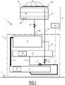
figure 1 is a synoptic drawing showing a refrigeration apparatus according to a first embodiment of the invention; -
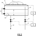
figure 2 is a synoptic drawing showing only a part of the refrigeration apparatus offigure 1 including a lubrication refrigerant tank; -
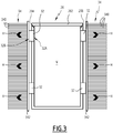
figure 3 is a synoptic drawing showing the lubricant refrigeration tank in transversal section; -
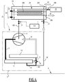
figure 4 is a synoptic drawing similar tofigure 1 , showing a refrigeration apparatus according to a second embodiment of the invention. -
Figure 1 represents arefrigeration apparatus 1, comprising a main refrigerant circuit 2 through which a refrigerant circulates in a closed loop circulation. The main refrigerant circuit 2 comprises four main components: apositive displacement compressor 4, also called volumetric compressor, acondenser 6, anexpansion valve 8, and anevaporator 10. The refrigerant circulates successively in these four components according to a thermodynamic cycle. - Preferably, in a steady-state, during high load operation of the refrigeration apparatus 1:
- in the
compressor 4, the refrigerant is in a gaseous state, and is compressed from a low pressure to a high pressure, which raises the temperature of the refrigerant from a low temperature to a high temperature; - in a
discharge line 12 connecting thecompressor 4 to thecondenser 6, the refrigerant is in a gaseous state, or essentially gaseous state, and is at the high temperature and the high pressure; - in the
condenser 6, the refrigerant is in a bi-phasic state, including gaseous and liquid refrigerant, and is condensed to a liquid state by thecondenser 6; - in a
line 14 connecting thecondenser 6 to theexpansion valve 8, the refrigerant is in a liquid state, or essentially liquid state, is at the high pressure, and may be at the high temperature or at a temperature between the high temperature and the low temperature; - in the
expansion valve 8, the refrigerant is brought to the low pressure, which lowers the temperature of the refrigerant to the low temperature while evaporating the refrigerant to the bi-phasic state; - in a
line 15 connecting theexpansion valve 8 to theevaporator 10, the refrigerant is in a biphasic-state, where a major part is liquid and a smaller part is gaseous, and the refrigerant is at the low temperature and the low pressure; - in the
evaporator 10, the refrigerant is in a bi-phasic state, including gaseous and liquid refrigerant, and is evaporated to a gaseous state by theevaporator 10 by absorbing heat from another medium, mainly water, which is cooled down when leaving theevaporator 10 ; - in a
suction line 16 connecting theevaporator 10 to thecompressor 4, the refrigerant is in a gaseous state, or essentially gaseous state, at the low pressure and at a low temperature, or at a temperature between the low and the high temperature. - For example, the low temperature is approximately between 5-10°C, the high temperature is approximately between 35-40°C, the low pressure is approximately between 3-4 bar, and the high pressure is approximately between 6-10 bar.
- Considering the above, the main circuit 2 comprises a high-pressure part, consisting in the
discharge line 12, thecondenser 6 and theline 14, and a low-pressure part, consisting in theline 15, theevaporator 10 and thesuction line 16. - In a part of the main circuit 2, which covers only a portion of the high-pressure part, preferably consisting in the
condenser 6 and theline 14, the refrigerant is mostly in liquid state and high pressure. - The positive-
displacement compressor 4 may be chosen between at least a scroll compressor, a screw compressor, a piston compressor, a rotary compressor, or a Roots compressor. Thecompressor 4 comprises non-shown rotors and bearings. - To insure the proper operation of the
compressor 4, it is essential that the rotors and the bearings are sufficiently lubricated with a liquid lubricant. - The refrigerant of the
refrigeration apparatus 1 is a fluid material chosen to ensure both functions of refrigerant and lubricant. Preferably, the refrigerant used in the apparatus is a hydrofluoroolefin (HFO), for example R1234ze (1,3,3,3-tetrafluoroprop-1-ene). There is therefore no lubrication oil present in the main refrigerant circuit 2. Therefrigeration apparatus 1 is operating an oil-free refrigerant cycle. - In the
condenser 6 and between thecondenser 6 and theexpansion valve 8, where the refrigerant of the main circuit 2 it mostly in liquid state and at high pressure, is the part of the main circuit 2 where the refrigerant is in the most appropriate state to be used as lubricant. - The
refrigeration apparatus 1 comprises alubrication refrigerant line 18 connected between thecondenser 6 and theexpansion valve 8, and connected to thecompressor 4 for lubrication of saidcompressor 4 with the liquid refrigerant. According to a non-shown embodiment, thelubrication refrigerant line 18 may be connected to thecondenser 6, for example in a bottom area of thecondenser 6. - To prevent a shortage of lubricant that may damage the
compressor 4 at first start or restart, therefrigeration apparatus 1 comprises alubrication refrigerant tank 20 connected to thelubrication refrigerant line 18 upstream thecompressor 4. Thelubrication tank 20 is configured to store liquid refrigerant for lubrication of thecompressor 4. Thelubricant tank 20 retains a given quantity of liquid refrigerant and is connected to thecompressor 4 so that a sufficient quantity of refrigerant may be provided to thecompressor 4 for lubrication purpose. - The
lubrication refrigerant tank 20 comprises means to cool down the refrigerant stored in thelubrication refrigerant tank 20 prior to a starting operation of therefrigeration apparatus 1. This permits to insure that the refrigerant is duly in liquid state prior to being injected into thecompressor 4, and creates a cold point to induce a phenomenon of spontaneous migration of the liquid refrigerant towards the tank 20.This cold point condenses any gaseous part of the refrigerant present in thetank 20, creating a depression that attracts gaseous and liquid refrigerant towards thetank 20. This phenomenon of spontaneous migration of the refrigerant makes it unnecessary to use a pump in thelubrication refrigerant line 18, as the circulation of liquid refrigerant towards thelubrication refrigerant tank 20 is self-induced. This avoids the use of costly parts and additional fluid lines, which may increase the cost of the refrigeration apparatus and lead to more failures due to additional moving parts. The means to cool down the refrigerant will be described in more detail below. - As shown on
figure 1 , therefrigerant tank 20 may be placed in a top area A of therefrigeration apparatus 1, and feed thecompressor 4 with lubrication refrigerant by gravity. In such a case, therefrigerant tank 20 may be placed so that thecompressor 4 is at a height below the height of therefrigerant tank 20 with respect to a floor F on which therefrigeration apparatus 1 is installed. Therefrigerant tank 20 is connected to thecompressor 4 by asection 180 of thelubrication refrigerant line 18. Thesection 180 is located under therefrigerant tank 20 and connects with abottom 200 of therefrigerant tank 20. - In one embodiment, the
lubrication refrigerant line 18 comprises avalve 22 upstream thetank 20 and avalve 24 downstream thetank 20. Thesevalves refrigeration apparatus 1. This allows that during standby, a minimal quantity of liquid refrigerant is kept in thetank 20. Thesevalves refrigeration apparatus 1, so that the stored liquid refrigerant can flow towards thecompressor 4 for lubrication, and that entry of new liquid refrigerant in thetank 20 due to the starting of the operation of the main circuit 2 is allowed. - The
valves refrigeration apparatus 1. The control unit CU may be configured to send control signals to thevalves refrigeration apparatus 1. The control unit CU may monitor the state of operation of therefrigeration apparatus 1 to detect stand-by periods of therefrigeration apparatus 1, starting commands by an operator, for example using the state of an ON/OFF command. The control unit CU may also detect a request for cooling or heating based on a temperature request for a water flow leaving theevaporator 10, compared to a measured temperature for the water leaving theevaporator 10. - The
lubrication refrigerant tank 20 preferably comprises detection means 26 of the level L of liquid refrigerant in thelubrication refrigerant tank 20. The detection means 26 may comprise, for example optical sensors, for detecting a low level L1 of lubrication refrigerant, or a high level L2, requested to allow thecompressor 4 to start. The level measures obtained by the detection means 26 may be transmitted to the control unit CU to allow or disallow starting of thecompressor 4. - According to an optional embodiment, the
refrigeration apparatus 1 may comprise at least one heating device mounted on thecondenser 6, or on a shell of theevaporator 10, or both, and being configured to heat up the refrigerant contained in thecondenser 6 and/or theevaporator 10 to induce migration of liquid refrigerant towards thelubrication refrigerant tank 20. For example, therefrigeration apparatus 1 may comprise a heating device formed by aheating belt 28 mounted on a non-shown shell of theevaporator 10, and a heating device formed by a heating belt 30 mounted on a non-shown shell of thecondenser 6. Theheating belts 28 and 30 may be electrical devices configured to be fed with electrical current before or during a start of therefrigeration device 1. Theheating belts 28 and 30 generate heat so that the refrigerant in the shells of theevaporator 10 and thecondenser 6 becomes hotter than the refrigerant present in the other places of the main circuit 2 and thelubrication refrigerant line 18, and migrates spontaneously towards thelubrication refrigerant tank 20. - As shown on
figures 1 to 3 , the means to cool down the refrigerant stored in thelubrication refrigerant tank 20 are formed by at least one thermoelectric cooler 32 provided on ashell 202 of thelubrication refrigerant tank 20 configured to cool an inner volume V of thelubrication refrigerant tank 20. The means to cool down the refrigerant stored in thelubrication refrigerant tank 20 also comprises at least oneheat sink 34 configured to reject a heat H generated by thethermoelectric cooler 32 outside thelubrication refrigerant tank 20. Thethermoelectric cooler 32, also called "Peltier module" generates a temperature difference between two plates separated by a semiconductor medium in which circulates an electrical current. A first plate called "cold side" becomes colder and can cool down another element, while a second plate called "hot side" becomes hotter and can heat up another element. In the present case, thethermoelectric cooler 32 is mounted so that it cools down theshell 202, thereby cooling down the refrigerant contained in thelubrication refrigerant tank 20. This allows producing more liquid refrigerant suitable for lubrication of thecompressor 4. At the same time the thermoelectric cooler 32 heats up theheat sink 34, which dissipates the heat H in the surrounding air. Thethermoelectric cooler 32 is fed with electrical current just before or during a start or restart of thecompressor 4. - As shown in more detail on
figure 3 , thelubrication refrigerant tank 20 may comprise a plurality ofthermoelectric coolers 32 mounted in sandwich between at least oneface 204 of theshell 202, and aheat sink 34 formed byheat dissipation fins 340 extending from abase plate 342. For example, thelubrication refrigerant tank 20 may comprise fourthermoelectric coolers 32 mounted in pairs on twoopposite faces lubrication refrigerant tank 20. Thelubrication refrigerant tank 20 may comprise twoheat sinks 34 mounted on thethermoelectric coolers 32 so as to form two sandwich-like mounts on theface 204 and on theface 206. Thethermoelectric coolers 32 have acold side 32A attached to theface hot side 32B attached to thebase plates 342. The heat H generated by thehot sides 32B is conducted in thebase plates 342 then dissipated in thefins 340. Thefins 340 are preferably placed in a vented place so that the heat H is dissipated to the outside air. - As shown in
figure 2 , therefrigeration apparatus 1 may comprise an electrical power supply unit PSU configured to feed the at least one thermoelectric cooler 32 with electrical current on a starting operation of therefrigeration apparatus 1. The electrical power supply unit PSU may be controlled by the control unit CU. On starting operations, the control unit CU commands the power supply unit PSU to feed electrical current to thethermoelectric cooler 32. Once the starting operation is over, thethermoelectric cooler 32 is deactivated by commanding stoppage of the feeding with electrical current by the power supply unit PSU. Thethermoelectric cooler 32 may be activated during limited durations, such as several seconds or minutes depending on the needs for lubrication refrigerant. - The
thermoelectric coolers 32 may be provided in any number, disposition or position on theshell 202 of thelubrication refrigerant tank 20. - A second embodiment of the invention is shown in
figure 4 . In this embodiment, elements common to the embodiment offigures 1 to 3 have the same references and work in the same way. - In this embodiment, the means to cool down the refrigerant stored in the
lubrication refrigerant tank 20 comprise: - a
heat exchanger 38 comprising atube 380 circulating within thelubrication refrigerant tank 20, thetube 380 having afirst end 382 in which a pressurized gas is released along arrow A1, and asecond end 384 connected to atmospheric pressure, and - a
removable container 40 of pressurized gas connected to thefirst end 382 of thetube 38, and configured to be opened toward thetube 380 so that the pressurized gas is released to the atmosphere as shown by arrow A2, along thetube 380 at a starting operation of therefrigeration apparatus 1. - The injection of the pressurized gas in the
tube 380 induces expansion of the pressurized gas in thetube 380, thereby reducing the temperature of the gas and cooling down the refrigerant contained in thelubrication refrigerant tank 20 by heat exchange between the expanded gas and the refrigerant through thetube 380. This produces more liquid refrigerant in thelubrication refrigerant tank 20 and activates migration of liquid refrigerant towards thelubrication refrigerant tank 20. The release of the pressurized gas may be operated at a first start of therefrigeration apparatus 1. Theremovable container 40 is then disconnected from thefirst end 382. - The
tube 380 may have a serpentine-like shape, configured to make maximal the heat exchange surface of thetube 380 in thelubrication refrigerant tank 20. Thefirst end 382 of thetube 380 may comprise avalve 386 that is opened at a starting operation of therefrigeration apparatus 1. - The
removable container 40 may contain a pressurized gas chosen amongst at least propane or carbon dioxide. - According to a non-shown embodiment of the invention, the means to cool down the refrigerant stored in the
lubrication refrigerant tank 20 may comprise a magnetic cooling device or any other suitable device. - Other embodiments may be formed by combining the technical features of the embodiments and variants described here-above within the scope of the claims.
Claims (16)
- A refrigeration apparatus (1) comprising:- a main refrigerant circuit (2) including a positive displacement compressor (4), a condenser (6), an expansion valve (8), and an evaporator (10), through which a refrigerant circulates successively in a closed loop circulation;- a lubrication refrigerant line (18) connected to the main refrigerant circuit (2) between the condenser (6) and the expansion valve (8) or to the condenser (6), in which circulates a portion of the refrigerant of the main refrigerant circuit (2) and connected to the compressor (4) for lubrication of said compressor (4) with the refrigerant;wherein the refrigeration apparatus comprises a lubrication refrigerant tank (20) connected to the lubrication refrigerant line (18) upstream the compressor (4), the lubrication tank (20) being configured to store liquid refrigerant for lubrication of the compressor (4);
and wherein the lubrication refrigerant tank (20) comprises means (32, 34; 38, 40) to cool down the refrigerant stored in the lubrication refrigerant tank (20) prior to a starting operation of the refrigeration apparatus (1). - A refrigeration apparatus according to claim 1, wherein the refrigerant tank (20) is placed in a top area (A) of the refrigeration apparatus (1), and feeds the compressor (4) with lubrication refrigerant by gravity.
- A refrigeration apparatus according to any preceding claim, wherein the lubrication refrigerant tank (20) comprises detection means (26) of the level (L) of liquid refrigerant in the lubrication refrigerant tank (20).
- A refrigeration apparatus according to any preceding claim, wherein the lubrication refrigerant line (18) comprises a valve (22) upstream the lubrication refrigerant tank (20) and a valve (24) downstream the lubrication refrigerant tank (20), and wherein these valves (22, 24) are closed during stand-by periods of the refrigeration apparatus (1) and opened during a starting operation of the refrigeration apparatus (1).
- A refrigeration apparatus according to claim 4, wherein the valves (22, 24) are solenoid valves that are controlled by a control unit (CU) of the refrigeration apparatus (1).
- A refrigeration apparatus according to any preceding claim, wherein it comprises at least one heating device (28, 30) mounted on the condenser (6), or on the evaporator (10), or both, and configured to heat up the refrigerant contained in the condenser (6) and/or the evaporator (10) to induce migration of liquid refrigerant towards the lubrication refrigerant tank (20).
- A refrigeration apparatus according to claim 6, wherein the heating device is an electrical heating belt (28, 30).
- A refrigeration apparatus according to any preceding claim, wherein the means to cool down the refrigerant stored in the lubrication refrigerant tank (20) are formed by at least one thermoelectric cooler (32) provided on a shell (202) of the lubrication refrigerant tank (20) and configured to cool an inner volume (V) of the lubrication refrigerant tank (20), and by at least one heat sink (34) configured to reject heat (H) generated by the thermoelectric cooler (32) outside the lubrication refrigerant tank (20).
- A refrigeration apparatus according to claim 8, wherein the lubrication refrigerant tank (20) comprises a plurality of thermoelectric coolers (32) mounted in sandwich between at least one face (204, 206) of the lubrication refrigerant tank (20) and the heat sink (34).
- A refrigeration apparatus according to claim 8 or 9, wherein the refrigeration apparatus (1) comprises an electrical power supply unit (PSU) configured to feed the at least one thermoelectric cooler (32) with electrical current on a starting operation of the refrigeration apparatus (1).
- A refrigeration apparatus according to any of claims 1 to 7, wherein the means to cool down the refrigerant stored in the lubrication refrigerant tank (20) comprise:- a heat exchanger (38) comprising a tube (380) circulating within the lubrication refrigerant tank (20), the tube (380) having a first end (382) in which a pressurized gas (A1) is released, and a second end (384) connected to atmospheric pressure;- a removable container (40) of pressurized gas connected to the first end (382) of the tube (380), and configured to be opened toward the tube (380) so that the pressurized gas is released (A2) to the atmosphere along the tube (380) at a starting operation of the refrigeration apparatus (1).
- A refrigeration apparatus according to claim 11, wherein the tube (380) has a serpentine-like shape.
- A refrigeration apparatus according to claim 11 or 12, wherein the first end (382) of the tube (380) comprises a valve (386) that is opened at a starting operation of the refrigeration apparatus (1).
- A refrigeration apparatus according to claim 11 or 12, wherein the removable container (40) contains a pressurized gas chosen amongst at least propane or carbon dioxide.
- A refrigeration apparatus according to any preceding claim, wherein it operates an oil free refrigerant cycle.
- A refrigeration apparatus according to any of claims 1 to 7, wherein the means to cool down the refrigerant stored in the lubrication refrigerant tank (20) comprise a magnetic cooling device.
Priority Applications (4)
| Application Number | Priority Date | Filing Date | Title |
|---|---|---|---|
| EP19175787.1A EP3742078B1 (en) | 2019-05-21 | 2019-05-21 | Refrigeration apparatus |
| ES19175787T ES2980113T3 (en) | 2019-05-21 | 2019-05-21 | Refrigeration appliance |
| US15/930,670 US11326813B2 (en) | 2019-05-21 | 2020-05-13 | Refrigeration apparatus |
| CN202010430168.1A CN111981715B (en) | 2019-05-21 | 2020-05-20 | Refrigerating apparatus |
Applications Claiming Priority (1)
| Application Number | Priority Date | Filing Date | Title |
|---|---|---|---|
| EP19175787.1A EP3742078B1 (en) | 2019-05-21 | 2019-05-21 | Refrigeration apparatus |
Publications (2)
| Publication Number | Publication Date |
|---|---|
| EP3742078A1 true EP3742078A1 (en) | 2020-11-25 |
| EP3742078B1 EP3742078B1 (en) | 2024-04-24 |
Family
ID=66630160
Family Applications (1)
| Application Number | Title | Priority Date | Filing Date |
|---|---|---|---|
| EP19175787.1A Active EP3742078B1 (en) | 2019-05-21 | 2019-05-21 | Refrigeration apparatus |
Country Status (4)
| Country | Link |
|---|---|
| US (1) | US11326813B2 (en) |
| EP (1) | EP3742078B1 (en) |
| CN (1) | CN111981715B (en) |
| ES (1) | ES2980113T3 (en) |
Citations (3)
| Publication number | Priority date | Publication date | Assignee | Title |
|---|---|---|---|---|
| EP1400765A2 (en) | 2002-09-17 | 2004-03-24 | Kabushiki Kaisha Kobe Seiko Sho | Screw refrigerating apparatus |
| WO2015142825A1 (en) * | 2014-03-18 | 2015-09-24 | Carrier Corporation | Refrigerant lube system |
| WO2017024101A1 (en) * | 2015-08-04 | 2017-02-09 | Carrier Corporation | Liquid sensing for refrigerant-lubricated bearings |
Family Cites Families (11)
| Publication number | Priority date | Publication date | Assignee | Title |
|---|---|---|---|---|
| JPH07318177A (en) * | 1994-05-27 | 1995-12-08 | Toyota Autom Loom Works Ltd | Freezing circuit using clutchless variable capacity compressor |
| US6176092B1 (en) * | 1998-10-09 | 2001-01-23 | American Standard Inc. | Oil-free liquid chiller |
| JP2001050601A (en) * | 1999-08-06 | 2001-02-23 | Mitsubishi Heavy Ind Ltd | Refrigerator |
| JP2001201195A (en) * | 2000-01-18 | 2001-07-27 | Mitsubishi Heavy Ind Ltd | Turbo refrigerating machine and method for lubricating compressor for turbo refrigerating machine |
| US6550258B1 (en) * | 2000-11-22 | 2003-04-22 | Carrier Corporation | Pre-start bearing lubrication for refrigeration system compressor |
| CN101784846A (en) * | 2007-08-14 | 2010-07-21 | 开利公司 | thermoelectric cooler for compressor motor |
| BRPI0819492A2 (en) * | 2007-12-20 | 2015-05-26 | Du Pont | "cooling system and method for diverting a reservoir into a cooling system" |
| WO2009091403A1 (en) * | 2008-01-17 | 2009-07-23 | Carrier Corporation | Refrigerant vapor compression system with lubricant cooler |
| US9032753B2 (en) * | 2012-03-22 | 2015-05-19 | Trane International Inc. | Electronics cooling using lubricant return for a shell-and-tube style evaporator |
| CN108027185B (en) * | 2015-10-27 | 2020-06-05 | 株式会社电装 | Refrigeration cycle device |
| JP6736357B2 (en) * | 2016-05-31 | 2020-08-05 | 三菱重工サーマルシステムズ株式会社 | Turbo refrigerator and start control method thereof |
-
2019
- 2019-05-21 EP EP19175787.1A patent/EP3742078B1/en active Active
- 2019-05-21 ES ES19175787T patent/ES2980113T3/en active Active
-
2020
- 2020-05-13 US US15/930,670 patent/US11326813B2/en active Active
- 2020-05-20 CN CN202010430168.1A patent/CN111981715B/en active Active
Patent Citations (3)
| Publication number | Priority date | Publication date | Assignee | Title |
|---|---|---|---|---|
| EP1400765A2 (en) | 2002-09-17 | 2004-03-24 | Kabushiki Kaisha Kobe Seiko Sho | Screw refrigerating apparatus |
| WO2015142825A1 (en) * | 2014-03-18 | 2015-09-24 | Carrier Corporation | Refrigerant lube system |
| WO2017024101A1 (en) * | 2015-08-04 | 2017-02-09 | Carrier Corporation | Liquid sensing for refrigerant-lubricated bearings |
Also Published As
| Publication number | Publication date |
|---|---|
| US20200370800A1 (en) | 2020-11-26 |
| ES2980113T3 (en) | 2024-09-30 |
| US11326813B2 (en) | 2022-05-10 |
| EP3742078B1 (en) | 2024-04-24 |
| CN111981715B (en) | 2023-07-04 |
| CN111981715A (en) | 2020-11-24 |
Similar Documents
| Publication | Publication Date | Title |
|---|---|---|
| KR100268111B1 (en) | Refrigerator Compressor | |
| JP4454197B2 (en) | Oil return from evaporator of refrigeration system using hot oil as power | |
| EP2602572B1 (en) | Closed- and gas circulation-type freezing apparatus and operation method thereof | |
| US20170016651A1 (en) | Engery system | |
| CN107314566A (en) | Refrigerant cools and lubricating system | |
| JP6527353B2 (en) | Superconductor cooling system | |
| US3548612A (en) | Refrigerating compressor with oil cooler | |
| KR20170110925A (en) | Refrigerant circulation method for improving the efficiency of the refrigerating cycle refrigeration | |
| KR200456849Y1 (en) | Refrigeration Vehicle Cooling Equipment | |
| KR20020035118A (en) | Thermosiphonic oil cooler for refrigeration chiller | |
| US11326813B2 (en) | Refrigeration apparatus | |
| CN111981716A (en) | Refrigeration equipment and use method thereof | |
| US11506429B2 (en) | Refrigeration apparatus | |
| CN211424747U (en) | Oilless bearing liquid supply system and air conditioning unit | |
| JP3221037U (en) | Power saving refrigeration cycle device. | |
| JPH10220885A (en) | Refrigerating machine | |
| RU2727220C2 (en) | Aircraft on-board equipment cooling method and system | |
| JPH0583666U (en) | Refrigeration equipment | |
| CN110986429A (en) | Oilless bearing liquid supply system and air conditioning unit | |
| CN119642456B (en) | Cooling water circulation control system and method for refrigerator | |
| JP2016099067A (en) | heat pump | |
| JP5162930B2 (en) | refrigerator | |
| JP6762624B1 (en) | Heat pump for refrigeration equipment, liquid quick freezing device using this | |
| CN120367855A (en) | Bearing lubrication structure, compressor, air conditioning system and control method of air conditioning system | |
| CN121828966A (en) | Refrigeration system control methods, refrigeration system and testing equipment |
Legal Events
| Date | Code | Title | Description |
|---|---|---|---|
| PUAI | Public reference made under article 153(3) epc to a published international application that has entered the european phase |
Free format text: ORIGINAL CODE: 0009012 |
|
| STAA | Information on the status of an ep patent application or granted ep patent |
Free format text: STATUS: THE APPLICATION HAS BEEN PUBLISHED |
|
| AK | Designated contracting states |
Kind code of ref document: A1 Designated state(s): AL AT BE BG CH CY CZ DE DK EE ES FI FR GB GR HR HU IE IS IT LI LT LU LV MC MK MT NL NO PL PT RO RS SE SI SK SM TR |
|
| AX | Request for extension of the european patent |
Extension state: BA ME |
|
| STAA | Information on the status of an ep patent application or granted ep patent |
Free format text: STATUS: REQUEST FOR EXAMINATION WAS MADE |
|
| 17P | Request for examination filed |
Effective date: 20210427 |
|
| RBV | Designated contracting states (corrected) |
Designated state(s): AL AT BE BG CH CY CZ DE DK EE ES FI FR GB GR HR HU IE IS IT LI LT LU LV MC MK MT NL NO PL PT RO RS SE SI SK SM TR |
|
| STAA | Information on the status of an ep patent application or granted ep patent |
Free format text: STATUS: EXAMINATION IS IN PROGRESS |
|
| 17Q | First examination report despatched |
Effective date: 20220314 |
|
| GRAP | Despatch of communication of intention to grant a patent |
Free format text: ORIGINAL CODE: EPIDOSNIGR1 |
|
| STAA | Information on the status of an ep patent application or granted ep patent |
Free format text: STATUS: GRANT OF PATENT IS INTENDED |
|
| RIC1 | Information provided on ipc code assigned before grant |
Ipc: F25B 21/02 20060101ALN20231121BHEP Ipc: F25B 31/00 20060101AFI20231121BHEP |
|
| INTG | Intention to grant announced |
Effective date: 20231206 |
|
| GRAS | Grant fee paid |
Free format text: ORIGINAL CODE: EPIDOSNIGR3 |
|
| GRAA | (expected) grant |
Free format text: ORIGINAL CODE: 0009210 |
|
| STAA | Information on the status of an ep patent application or granted ep patent |
Free format text: STATUS: THE PATENT HAS BEEN GRANTED |
|
| AK | Designated contracting states |
Kind code of ref document: B1 Designated state(s): AL AT BE BG CH CY CZ DE DK EE ES FI FR GB GR HR HU IE IS IT LI LT LU LV MC MK MT NL NO PL PT RO RS SE SI SK SM TR |
|
| REG | Reference to a national code |
Ref country code: GB Ref legal event code: FG4D |
|
| REG | Reference to a national code |
Ref country code: CH Ref legal event code: EP |
|
| REG | Reference to a national code |
Ref country code: DE Ref legal event code: R096 Ref document number: 602019050735 Country of ref document: DE |
|
| REG | Reference to a national code |
Ref country code: IE Ref legal event code: FG4D |
|
| PGFP | Annual fee paid to national office [announced via postgrant information from national office to epo] |
Ref country code: ES Payment date: 20240605 Year of fee payment: 6 |
|
| REG | Reference to a national code |
Ref country code: LT Ref legal event code: MG9D |
|
| REG | Reference to a national code |
Ref country code: NL Ref legal event code: MP Effective date: 20240424 |
|
| PGFP | Annual fee paid to national office [announced via postgrant information from national office to epo] |
Ref country code: BE Payment date: 20240515 Year of fee payment: 6 |
|
| REG | Reference to a national code |
Ref country code: AT Ref legal event code: MK05 Ref document number: 1679992 Country of ref document: AT Kind code of ref document: T Effective date: 20240424 |
|
| PG25 | Lapsed in a contracting state [announced via postgrant information from national office to epo] |
Ref country code: NL Free format text: LAPSE BECAUSE OF FAILURE TO SUBMIT A TRANSLATION OF THE DESCRIPTION OR TO PAY THE FEE WITHIN THE PRESCRIBED TIME-LIMIT Effective date: 20240424 |
|
| PG25 | Lapsed in a contracting state [announced via postgrant information from national office to epo] |
Ref country code: NL Free format text: LAPSE BECAUSE OF FAILURE TO SUBMIT A TRANSLATION OF THE DESCRIPTION OR TO PAY THE FEE WITHIN THE PRESCRIBED TIME-LIMIT Effective date: 20240424 |
|
| REG | Reference to a national code |
Ref country code: ES Ref legal event code: FG2A Ref document number: 2980113 Country of ref document: ES Kind code of ref document: T3 Effective date: 20240930 |
|
| PG25 | Lapsed in a contracting state [announced via postgrant information from national office to epo] |
Ref country code: IS Free format text: LAPSE BECAUSE OF FAILURE TO SUBMIT A TRANSLATION OF THE DESCRIPTION OR TO PAY THE FEE WITHIN THE PRESCRIBED TIME-LIMIT Effective date: 20240824 |
|
| PG25 | Lapsed in a contracting state [announced via postgrant information from national office to epo] |
Ref country code: BG Free format text: LAPSE BECAUSE OF FAILURE TO SUBMIT A TRANSLATION OF THE DESCRIPTION OR TO PAY THE FEE WITHIN THE PRESCRIBED TIME-LIMIT Effective date: 20240424 |
|
| PG25 | Lapsed in a contracting state [announced via postgrant information from national office to epo] |
Ref country code: FI Free format text: LAPSE BECAUSE OF FAILURE TO SUBMIT A TRANSLATION OF THE DESCRIPTION OR TO PAY THE FEE WITHIN THE PRESCRIBED TIME-LIMIT Effective date: 20240424 Ref country code: HR Free format text: LAPSE BECAUSE OF FAILURE TO SUBMIT A TRANSLATION OF THE DESCRIPTION OR TO PAY THE FEE WITHIN THE PRESCRIBED TIME-LIMIT Effective date: 20240424 |
|
| PG25 | Lapsed in a contracting state [announced via postgrant information from national office to epo] |
Ref country code: GR Free format text: LAPSE BECAUSE OF FAILURE TO SUBMIT A TRANSLATION OF THE DESCRIPTION OR TO PAY THE FEE WITHIN THE PRESCRIBED TIME-LIMIT Effective date: 20240725 |
|
| PG25 | Lapsed in a contracting state [announced via postgrant information from national office to epo] |
Ref country code: PT Free format text: LAPSE BECAUSE OF FAILURE TO SUBMIT A TRANSLATION OF THE DESCRIPTION OR TO PAY THE FEE WITHIN THE PRESCRIBED TIME-LIMIT Effective date: 20240826 |
|
| PG25 | Lapsed in a contracting state [announced via postgrant information from national office to epo] |
Ref country code: AT Free format text: LAPSE BECAUSE OF FAILURE TO SUBMIT A TRANSLATION OF THE DESCRIPTION OR TO PAY THE FEE WITHIN THE PRESCRIBED TIME-LIMIT Effective date: 20240424 |
|
| PG25 | Lapsed in a contracting state [announced via postgrant information from national office to epo] |
Ref country code: PL Free format text: LAPSE BECAUSE OF FAILURE TO SUBMIT A TRANSLATION OF THE DESCRIPTION OR TO PAY THE FEE WITHIN THE PRESCRIBED TIME-LIMIT Effective date: 20240424 |
|
| PG25 | Lapsed in a contracting state [announced via postgrant information from national office to epo] |
Ref country code: LV Free format text: LAPSE BECAUSE OF FAILURE TO SUBMIT A TRANSLATION OF THE DESCRIPTION OR TO PAY THE FEE WITHIN THE PRESCRIBED TIME-LIMIT Effective date: 20240424 |
|
| PG25 | Lapsed in a contracting state [announced via postgrant information from national office to epo] |
Ref country code: PT Free format text: LAPSE BECAUSE OF FAILURE TO SUBMIT A TRANSLATION OF THE DESCRIPTION OR TO PAY THE FEE WITHIN THE PRESCRIBED TIME-LIMIT Effective date: 20240826 Ref country code: PL Free format text: LAPSE BECAUSE OF FAILURE TO SUBMIT A TRANSLATION OF THE DESCRIPTION OR TO PAY THE FEE WITHIN THE PRESCRIBED TIME-LIMIT Effective date: 20240424 Ref country code: NO Free format text: LAPSE BECAUSE OF FAILURE TO SUBMIT A TRANSLATION OF THE DESCRIPTION OR TO PAY THE FEE WITHIN THE PRESCRIBED TIME-LIMIT Effective date: 20240724 Ref country code: LV Free format text: LAPSE BECAUSE OF FAILURE TO SUBMIT A TRANSLATION OF THE DESCRIPTION OR TO PAY THE FEE WITHIN THE PRESCRIBED TIME-LIMIT Effective date: 20240424 Ref country code: IS Free format text: LAPSE BECAUSE OF FAILURE TO SUBMIT A TRANSLATION OF THE DESCRIPTION OR TO PAY THE FEE WITHIN THE PRESCRIBED TIME-LIMIT Effective date: 20240824 Ref country code: HR Free format text: LAPSE BECAUSE OF FAILURE TO SUBMIT A TRANSLATION OF THE DESCRIPTION OR TO PAY THE FEE WITHIN THE PRESCRIBED TIME-LIMIT Effective date: 20240424 Ref country code: GR Free format text: LAPSE BECAUSE OF FAILURE TO SUBMIT A TRANSLATION OF THE DESCRIPTION OR TO PAY THE FEE WITHIN THE PRESCRIBED TIME-LIMIT Effective date: 20240725 Ref country code: FI Free format text: LAPSE BECAUSE OF FAILURE TO SUBMIT A TRANSLATION OF THE DESCRIPTION OR TO PAY THE FEE WITHIN THE PRESCRIBED TIME-LIMIT Effective date: 20240424 Ref country code: BG Free format text: LAPSE BECAUSE OF FAILURE TO SUBMIT A TRANSLATION OF THE DESCRIPTION OR TO PAY THE FEE WITHIN THE PRESCRIBED TIME-LIMIT Effective date: 20240424 Ref country code: AT Free format text: LAPSE BECAUSE OF FAILURE TO SUBMIT A TRANSLATION OF THE DESCRIPTION OR TO PAY THE FEE WITHIN THE PRESCRIBED TIME-LIMIT Effective date: 20240424 Ref country code: RS Free format text: LAPSE BECAUSE OF FAILURE TO SUBMIT A TRANSLATION OF THE DESCRIPTION OR TO PAY THE FEE WITHIN THE PRESCRIBED TIME-LIMIT Effective date: 20240724 |
|
| REG | Reference to a national code |
Ref country code: CH Ref legal event code: PL |
|
| PG25 | Lapsed in a contracting state [announced via postgrant information from national office to epo] |
Ref country code: DK Free format text: LAPSE BECAUSE OF FAILURE TO SUBMIT A TRANSLATION OF THE DESCRIPTION OR TO PAY THE FEE WITHIN THE PRESCRIBED TIME-LIMIT Effective date: 20240424 |
|
| PG25 | Lapsed in a contracting state [announced via postgrant information from national office to epo] |
Ref country code: LU Free format text: LAPSE BECAUSE OF NON-PAYMENT OF DUE FEES Effective date: 20240521 |
|
| PG25 | Lapsed in a contracting state [announced via postgrant information from national office to epo] |
Ref country code: EE Free format text: LAPSE BECAUSE OF FAILURE TO SUBMIT A TRANSLATION OF THE DESCRIPTION OR TO PAY THE FEE WITHIN THE PRESCRIBED TIME-LIMIT Effective date: 20240424 |
|
| PG25 | Lapsed in a contracting state [announced via postgrant information from national office to epo] |
Ref country code: CZ Free format text: LAPSE BECAUSE OF FAILURE TO SUBMIT A TRANSLATION OF THE DESCRIPTION OR TO PAY THE FEE WITHIN THE PRESCRIBED TIME-LIMIT Effective date: 20240424 |
|
| PG25 | Lapsed in a contracting state [announced via postgrant information from national office to epo] |
Ref country code: RO Free format text: LAPSE BECAUSE OF FAILURE TO SUBMIT A TRANSLATION OF THE DESCRIPTION OR TO PAY THE FEE WITHIN THE PRESCRIBED TIME-LIMIT Effective date: 20240424 Ref country code: SK Free format text: LAPSE BECAUSE OF FAILURE TO SUBMIT A TRANSLATION OF THE DESCRIPTION OR TO PAY THE FEE WITHIN THE PRESCRIBED TIME-LIMIT Effective date: 20240424 |
|
| REG | Reference to a national code |
Ref country code: DE Ref legal event code: R097 Ref document number: 602019050735 Country of ref document: DE |
|
| PG25 | Lapsed in a contracting state [announced via postgrant information from national office to epo] |
Ref country code: SM Free format text: LAPSE BECAUSE OF FAILURE TO SUBMIT A TRANSLATION OF THE DESCRIPTION OR TO PAY THE FEE WITHIN THE PRESCRIBED TIME-LIMIT Effective date: 20240424 |
|
| PG25 | Lapsed in a contracting state [announced via postgrant information from national office to epo] |
Ref country code: SM Free format text: LAPSE BECAUSE OF FAILURE TO SUBMIT A TRANSLATION OF THE DESCRIPTION OR TO PAY THE FEE WITHIN THE PRESCRIBED TIME-LIMIT Effective date: 20240424 Ref country code: SK Free format text: LAPSE BECAUSE OF FAILURE TO SUBMIT A TRANSLATION OF THE DESCRIPTION OR TO PAY THE FEE WITHIN THE PRESCRIBED TIME-LIMIT Effective date: 20240424 Ref country code: RO Free format text: LAPSE BECAUSE OF FAILURE TO SUBMIT A TRANSLATION OF THE DESCRIPTION OR TO PAY THE FEE WITHIN THE PRESCRIBED TIME-LIMIT Effective date: 20240424 Ref country code: LU Free format text: LAPSE BECAUSE OF NON-PAYMENT OF DUE FEES Effective date: 20240521 Ref country code: EE Free format text: LAPSE BECAUSE OF FAILURE TO SUBMIT A TRANSLATION OF THE DESCRIPTION OR TO PAY THE FEE WITHIN THE PRESCRIBED TIME-LIMIT Effective date: 20240424 Ref country code: DK Free format text: LAPSE BECAUSE OF FAILURE TO SUBMIT A TRANSLATION OF THE DESCRIPTION OR TO PAY THE FEE WITHIN THE PRESCRIBED TIME-LIMIT Effective date: 20240424 Ref country code: CZ Free format text: LAPSE BECAUSE OF FAILURE TO SUBMIT A TRANSLATION OF THE DESCRIPTION OR TO PAY THE FEE WITHIN THE PRESCRIBED TIME-LIMIT Effective date: 20240424 Ref country code: MC Free format text: LAPSE BECAUSE OF FAILURE TO SUBMIT A TRANSLATION OF THE DESCRIPTION OR TO PAY THE FEE WITHIN THE PRESCRIBED TIME-LIMIT Effective date: 20240424 Ref country code: CH Free format text: LAPSE BECAUSE OF NON-PAYMENT OF DUE FEES Effective date: 20240531 |
|
| PLBE | No opposition filed within time limit |
Free format text: ORIGINAL CODE: 0009261 |
|
| STAA | Information on the status of an ep patent application or granted ep patent |
Free format text: STATUS: NO OPPOSITION FILED WITHIN TIME LIMIT |
|
| GBPC | Gb: european patent ceased through non-payment of renewal fee |
Effective date: 20240724 |
|
| 26N | No opposition filed |
Effective date: 20250127 |
|
| PG25 | Lapsed in a contracting state [announced via postgrant information from national office to epo] |
Ref country code: IE Free format text: LAPSE BECAUSE OF NON-PAYMENT OF DUE FEES Effective date: 20240521 |
|
| PG25 | Lapsed in a contracting state [announced via postgrant information from national office to epo] |
Ref country code: SI Free format text: LAPSE BECAUSE OF FAILURE TO SUBMIT A TRANSLATION OF THE DESCRIPTION OR TO PAY THE FEE WITHIN THE PRESCRIBED TIME-LIMIT Effective date: 20240424 |
|
| PG25 | Lapsed in a contracting state [announced via postgrant information from national office to epo] |
Ref country code: GB Free format text: LAPSE BECAUSE OF NON-PAYMENT OF DUE FEES Effective date: 20240724 |
|
| PGFP | Annual fee paid to national office [announced via postgrant information from national office to epo] |
Ref country code: DE Payment date: 20250423 Year of fee payment: 7 |
|
| PGFP | Annual fee paid to national office [announced via postgrant information from national office to epo] |
Ref country code: FR Payment date: 20250423 Year of fee payment: 7 |
|
| PG25 | Lapsed in a contracting state [announced via postgrant information from national office to epo] |
Ref country code: CY Free format text: LAPSE BECAUSE OF FAILURE TO SUBMIT A TRANSLATION OF THE DESCRIPTION OR TO PAY THE FEE WITHIN THE PRESCRIBED TIME-LIMIT; INVALID AB INITIO Effective date: 20190521 |
|
| PG25 | Lapsed in a contracting state [announced via postgrant information from national office to epo] |
Ref country code: HU Free format text: LAPSE BECAUSE OF FAILURE TO SUBMIT A TRANSLATION OF THE DESCRIPTION OR TO PAY THE FEE WITHIN THE PRESCRIBED TIME-LIMIT; INVALID AB INITIO Effective date: 20190521 |
|
| PG25 | Lapsed in a contracting state [announced via postgrant information from national office to epo] |
Ref country code: SE Free format text: LAPSE BECAUSE OF FAILURE TO SUBMIT A TRANSLATION OF THE DESCRIPTION OR TO PAY THE FEE WITHIN THE PRESCRIBED TIME-LIMIT Effective date: 20240424 |
|
| PG25 | Lapsed in a contracting state [announced via postgrant information from national office to epo] |
Ref country code: IT Free format text: LAPSE BECAUSE OF NON-PAYMENT OF DUE FEES Effective date: 20240521 |
|
| REG | Reference to a national code |
Ref country code: BE Ref legal event code: MM Effective date: 20250531 |
|
| PG25 | Lapsed in a contracting state [announced via postgrant information from national office to epo] |
Ref country code: IT Free format text: LAPSE BECAUSE OF NON-PAYMENT OF DUE FEES Effective date: 20240521 Ref country code: BE Free format text: LAPSE BECAUSE OF NON-PAYMENT OF DUE FEES Effective date: 20250531 |
|
| PGFP | Annual fee paid to national office [announced via postgrant information from national office to epo] |
Ref country code: IT Payment date: 20240418 Year of fee payment: 6 |
|
| PGRI | Patent reinstated in contracting state [announced from national office to epo] |
Ref country code: IT Effective date: 20240930 |