EP3742039A1 - Gas distribution circuit for feeding a gas engine for a work vehicle - Google Patents
Gas distribution circuit for feeding a gas engine for a work vehicle Download PDFInfo
- Publication number
- EP3742039A1 EP3742039A1 EP20175881.0A EP20175881A EP3742039A1 EP 3742039 A1 EP3742039 A1 EP 3742039A1 EP 20175881 A EP20175881 A EP 20175881A EP 3742039 A1 EP3742039 A1 EP 3742039A1
- Authority
- EP
- European Patent Office
- Prior art keywords
- distribution circuit
- gas distribution
- conduit
- gas
- tank module
- Prior art date
- Legal status (The legal status is an assumption and is not a legal conclusion. Google has not performed a legal analysis and makes no representation as to the accuracy of the status listed.)
- Granted
Links
Images
Classifications
-
- F—MECHANICAL ENGINEERING; LIGHTING; HEATING; WEAPONS; BLASTING
- F17—STORING OR DISTRIBUTING GASES OR LIQUIDS
- F17C—VESSELS FOR CONTAINING OR STORING COMPRESSED, LIQUEFIED OR SOLIDIFIED GASES; FIXED-CAPACITY GAS-HOLDERS; FILLING VESSELS WITH, OR DISCHARGING FROM VESSELS, COMPRESSED, LIQUEFIED, OR SOLIDIFIED GASES
- F17C7/00—Methods or apparatus for discharging liquefied, solidified, or compressed gases from pressure vessels, not covered by another subclass
-
- F—MECHANICAL ENGINEERING; LIGHTING; HEATING; WEAPONS; BLASTING
- F17—STORING OR DISTRIBUTING GASES OR LIQUIDS
- F17C—VESSELS FOR CONTAINING OR STORING COMPRESSED, LIQUEFIED OR SOLIDIFIED GASES; FIXED-CAPACITY GAS-HOLDERS; FILLING VESSELS WITH, OR DISCHARGING FROM VESSELS, COMPRESSED, LIQUEFIED, OR SOLIDIFIED GASES
- F17C2201/00—Vessel construction, in particular geometry, arrangement or size
- F17C2201/05—Size
- F17C2201/054—Size medium (>1 m3)
-
- F—MECHANICAL ENGINEERING; LIGHTING; HEATING; WEAPONS; BLASTING
- F17—STORING OR DISTRIBUTING GASES OR LIQUIDS
- F17C—VESSELS FOR CONTAINING OR STORING COMPRESSED, LIQUEFIED OR SOLIDIFIED GASES; FIXED-CAPACITY GAS-HOLDERS; FILLING VESSELS WITH, OR DISCHARGING FROM VESSELS, COMPRESSED, LIQUEFIED, OR SOLIDIFIED GASES
- F17C2201/00—Vessel construction, in particular geometry, arrangement or size
- F17C2201/05—Size
- F17C2201/056—Small (<1 m3)
-
- F—MECHANICAL ENGINEERING; LIGHTING; HEATING; WEAPONS; BLASTING
- F17—STORING OR DISTRIBUTING GASES OR LIQUIDS
- F17C—VESSELS FOR CONTAINING OR STORING COMPRESSED, LIQUEFIED OR SOLIDIFIED GASES; FIXED-CAPACITY GAS-HOLDERS; FILLING VESSELS WITH, OR DISCHARGING FROM VESSELS, COMPRESSED, LIQUEFIED, OR SOLIDIFIED GASES
- F17C2205/00—Vessel construction, in particular mounting arrangements, attachments or identifications means
- F17C2205/01—Mounting arrangements
- F17C2205/0123—Mounting arrangements characterised by number of vessels
- F17C2205/013—Two or more vessels
- F17C2205/0134—Two or more vessels characterised by the presence of fluid connection between vessels
- F17C2205/0142—Two or more vessels characterised by the presence of fluid connection between vessels bundled in parallel
-
- F—MECHANICAL ENGINEERING; LIGHTING; HEATING; WEAPONS; BLASTING
- F17—STORING OR DISTRIBUTING GASES OR LIQUIDS
- F17C—VESSELS FOR CONTAINING OR STORING COMPRESSED, LIQUEFIED OR SOLIDIFIED GASES; FIXED-CAPACITY GAS-HOLDERS; FILLING VESSELS WITH, OR DISCHARGING FROM VESSELS, COMPRESSED, LIQUEFIED, OR SOLIDIFIED GASES
- F17C2205/00—Vessel construction, in particular mounting arrangements, attachments or identifications means
- F17C2205/03—Fluid connections, filters, valves, closure means or other attachments
- F17C2205/0302—Fittings, valves, filters, or components in connection with the gas storage device
- F17C2205/0323—Valves
- F17C2205/0326—Valves electrically actuated
-
- F—MECHANICAL ENGINEERING; LIGHTING; HEATING; WEAPONS; BLASTING
- F17—STORING OR DISTRIBUTING GASES OR LIQUIDS
- F17C—VESSELS FOR CONTAINING OR STORING COMPRESSED, LIQUEFIED OR SOLIDIFIED GASES; FIXED-CAPACITY GAS-HOLDERS; FILLING VESSELS WITH, OR DISCHARGING FROM VESSELS, COMPRESSED, LIQUEFIED, OR SOLIDIFIED GASES
- F17C2205/00—Vessel construction, in particular mounting arrangements, attachments or identifications means
- F17C2205/03—Fluid connections, filters, valves, closure means or other attachments
- F17C2205/0302—Fittings, valves, filters, or components in connection with the gas storage device
- F17C2205/0323—Valves
- F17C2205/0335—Check-valves or non-return valves
-
- F—MECHANICAL ENGINEERING; LIGHTING; HEATING; WEAPONS; BLASTING
- F17—STORING OR DISTRIBUTING GASES OR LIQUIDS
- F17C—VESSELS FOR CONTAINING OR STORING COMPRESSED, LIQUEFIED OR SOLIDIFIED GASES; FIXED-CAPACITY GAS-HOLDERS; FILLING VESSELS WITH, OR DISCHARGING FROM VESSELS, COMPRESSED, LIQUEFIED, OR SOLIDIFIED GASES
- F17C2221/00—Handled fluid, in particular type of fluid
- F17C2221/03—Mixtures
- F17C2221/032—Hydrocarbons
- F17C2221/033—Methane, e.g. natural gas, CNG, LNG, GNL, GNC, PLNG
-
- F—MECHANICAL ENGINEERING; LIGHTING; HEATING; WEAPONS; BLASTING
- F17—STORING OR DISTRIBUTING GASES OR LIQUIDS
- F17C—VESSELS FOR CONTAINING OR STORING COMPRESSED, LIQUEFIED OR SOLIDIFIED GASES; FIXED-CAPACITY GAS-HOLDERS; FILLING VESSELS WITH, OR DISCHARGING FROM VESSELS, COMPRESSED, LIQUEFIED, OR SOLIDIFIED GASES
- F17C2223/00—Handled fluid before transfer, i.e. state of fluid when stored in the vessel or before transfer from the vessel
- F17C2223/01—Handled fluid before transfer, i.e. state of fluid when stored in the vessel or before transfer from the vessel characterised by the phase
- F17C2223/0107—Single phase
- F17C2223/0123—Single phase gaseous, e.g. CNG, GNC
-
- F—MECHANICAL ENGINEERING; LIGHTING; HEATING; WEAPONS; BLASTING
- F17—STORING OR DISTRIBUTING GASES OR LIQUIDS
- F17C—VESSELS FOR CONTAINING OR STORING COMPRESSED, LIQUEFIED OR SOLIDIFIED GASES; FIXED-CAPACITY GAS-HOLDERS; FILLING VESSELS WITH, OR DISCHARGING FROM VESSELS, COMPRESSED, LIQUEFIED, OR SOLIDIFIED GASES
- F17C2223/00—Handled fluid before transfer, i.e. state of fluid when stored in the vessel or before transfer from the vessel
- F17C2223/03—Handled fluid before transfer, i.e. state of fluid when stored in the vessel or before transfer from the vessel characterised by the pressure level
- F17C2223/035—High pressure (>10 bar)
-
- F—MECHANICAL ENGINEERING; LIGHTING; HEATING; WEAPONS; BLASTING
- F17—STORING OR DISTRIBUTING GASES OR LIQUIDS
- F17C—VESSELS FOR CONTAINING OR STORING COMPRESSED, LIQUEFIED OR SOLIDIFIED GASES; FIXED-CAPACITY GAS-HOLDERS; FILLING VESSELS WITH, OR DISCHARGING FROM VESSELS, COMPRESSED, LIQUEFIED, OR SOLIDIFIED GASES
- F17C2223/00—Handled fluid before transfer, i.e. state of fluid when stored in the vessel or before transfer from the vessel
- F17C2223/03—Handled fluid before transfer, i.e. state of fluid when stored in the vessel or before transfer from the vessel characterised by the pressure level
- F17C2223/036—Very high pressure (>80 bar)
-
- F—MECHANICAL ENGINEERING; LIGHTING; HEATING; WEAPONS; BLASTING
- F17—STORING OR DISTRIBUTING GASES OR LIQUIDS
- F17C—VESSELS FOR CONTAINING OR STORING COMPRESSED, LIQUEFIED OR SOLIDIFIED GASES; FIXED-CAPACITY GAS-HOLDERS; FILLING VESSELS WITH, OR DISCHARGING FROM VESSELS, COMPRESSED, LIQUEFIED, OR SOLIDIFIED GASES
- F17C2227/00—Transfer of fluids, i.e. method or means for transferring the fluid; Heat exchange with the fluid
- F17C2227/04—Methods for emptying or filling
- F17C2227/041—Methods for emptying or filling vessel by vessel
- F17C2227/042—Methods for emptying or filling vessel by vessel with change-over from one vessel to another
-
- F—MECHANICAL ENGINEERING; LIGHTING; HEATING; WEAPONS; BLASTING
- F17—STORING OR DISTRIBUTING GASES OR LIQUIDS
- F17C—VESSELS FOR CONTAINING OR STORING COMPRESSED, LIQUEFIED OR SOLIDIFIED GASES; FIXED-CAPACITY GAS-HOLDERS; FILLING VESSELS WITH, OR DISCHARGING FROM VESSELS, COMPRESSED, LIQUEFIED, OR SOLIDIFIED GASES
- F17C2227/00—Transfer of fluids, i.e. method or means for transferring the fluid; Heat exchange with the fluid
- F17C2227/04—Methods for emptying or filling
- F17C2227/048—Methods for emptying or filling by maintaining residual pressure
-
- F—MECHANICAL ENGINEERING; LIGHTING; HEATING; WEAPONS; BLASTING
- F17—STORING OR DISTRIBUTING GASES OR LIQUIDS
- F17C—VESSELS FOR CONTAINING OR STORING COMPRESSED, LIQUEFIED OR SOLIDIFIED GASES; FIXED-CAPACITY GAS-HOLDERS; FILLING VESSELS WITH, OR DISCHARGING FROM VESSELS, COMPRESSED, LIQUEFIED, OR SOLIDIFIED GASES
- F17C2250/00—Accessories; Control means; Indicating, measuring or monitoring of parameters
- F17C2250/03—Control means
- F17C2250/032—Control means using computers
-
- F—MECHANICAL ENGINEERING; LIGHTING; HEATING; WEAPONS; BLASTING
- F17—STORING OR DISTRIBUTING GASES OR LIQUIDS
- F17C—VESSELS FOR CONTAINING OR STORING COMPRESSED, LIQUEFIED OR SOLIDIFIED GASES; FIXED-CAPACITY GAS-HOLDERS; FILLING VESSELS WITH, OR DISCHARGING FROM VESSELS, COMPRESSED, LIQUEFIED, OR SOLIDIFIED GASES
- F17C2250/00—Accessories; Control means; Indicating, measuring or monitoring of parameters
- F17C2250/04—Indicating or measuring of parameters as input values
- F17C2250/0404—Parameters indicated or measured
- F17C2250/043—Pressure
- F17C2250/0434—Pressure difference
-
- F—MECHANICAL ENGINEERING; LIGHTING; HEATING; WEAPONS; BLASTING
- F17—STORING OR DISTRIBUTING GASES OR LIQUIDS
- F17C—VESSELS FOR CONTAINING OR STORING COMPRESSED, LIQUEFIED OR SOLIDIFIED GASES; FIXED-CAPACITY GAS-HOLDERS; FILLING VESSELS WITH, OR DISCHARGING FROM VESSELS, COMPRESSED, LIQUEFIED, OR SOLIDIFIED GASES
- F17C2250/00—Accessories; Control means; Indicating, measuring or monitoring of parameters
- F17C2250/06—Controlling or regulating of parameters as output values
- F17C2250/0605—Parameters
- F17C2250/0636—Flow or movement of content
-
- F—MECHANICAL ENGINEERING; LIGHTING; HEATING; WEAPONS; BLASTING
- F17—STORING OR DISTRIBUTING GASES OR LIQUIDS
- F17C—VESSELS FOR CONTAINING OR STORING COMPRESSED, LIQUEFIED OR SOLIDIFIED GASES; FIXED-CAPACITY GAS-HOLDERS; FILLING VESSELS WITH, OR DISCHARGING FROM VESSELS, COMPRESSED, LIQUEFIED, OR SOLIDIFIED GASES
- F17C2250/00—Accessories; Control means; Indicating, measuring or monitoring of parameters
- F17C2250/07—Actions triggered by measured parameters
- F17C2250/072—Action when predefined value is reached
- F17C2250/077—Action when predefined value is reached when empty
-
- F—MECHANICAL ENGINEERING; LIGHTING; HEATING; WEAPONS; BLASTING
- F17—STORING OR DISTRIBUTING GASES OR LIQUIDS
- F17C—VESSELS FOR CONTAINING OR STORING COMPRESSED, LIQUEFIED OR SOLIDIFIED GASES; FIXED-CAPACITY GAS-HOLDERS; FILLING VESSELS WITH, OR DISCHARGING FROM VESSELS, COMPRESSED, LIQUEFIED, OR SOLIDIFIED GASES
- F17C2260/00—Purposes of gas storage and gas handling
- F17C2260/02—Improving properties related to fluid or fluid transfer
-
- F—MECHANICAL ENGINEERING; LIGHTING; HEATING; WEAPONS; BLASTING
- F17—STORING OR DISTRIBUTING GASES OR LIQUIDS
- F17C—VESSELS FOR CONTAINING OR STORING COMPRESSED, LIQUEFIED OR SOLIDIFIED GASES; FIXED-CAPACITY GAS-HOLDERS; FILLING VESSELS WITH, OR DISCHARGING FROM VESSELS, COMPRESSED, LIQUEFIED, OR SOLIDIFIED GASES
- F17C2265/00—Effects achieved by gas storage or gas handling
- F17C2265/06—Fluid distribution
- F17C2265/066—Fluid distribution for feeding engines for propulsion
-
- F—MECHANICAL ENGINEERING; LIGHTING; HEATING; WEAPONS; BLASTING
- F17—STORING OR DISTRIBUTING GASES OR LIQUIDS
- F17C—VESSELS FOR CONTAINING OR STORING COMPRESSED, LIQUEFIED OR SOLIDIFIED GASES; FIXED-CAPACITY GAS-HOLDERS; FILLING VESSELS WITH, OR DISCHARGING FROM VESSELS, COMPRESSED, LIQUEFIED, OR SOLIDIFIED GASES
- F17C2270/00—Applications
- F17C2270/01—Applications for fluid transport or storage
- F17C2270/0165—Applications for fluid transport or storage on the road
- F17C2270/0168—Applications for fluid transport or storage on the road by vehicles
Definitions
- the present invention concerns a gas distribution circuit, in particular a gas distribution circuit for feeding a gas engine for a work vehicle.
- Tractors may be powered by using gas fuel in order to reduce the emissions with respect to other typology of fossil fuels.
- CNG Compressed Natural Gas
- the tractor has to be used with an auxiliary gas tank that is carried by an auxiliary unit such as a towed implement or a range extender such as the front or rear hitch or fixed to the front on the front axle support.
- an auxiliary unit such as a towed implement or a range extender such as the front or rear hitch or fixed to the front on the front axle support.
- main tank is used first for feeding the gas engine and, when such tank is almost empty, the auxiliary tank is used for feeding the engine.
- main tank of the tractor has not sufficient gas for returning to its recovery, leaving its user in the fields without possibility of moving away.
- implements or range extenders provided with gas tanks are not usually driven on roads because they may be not homologated for such configuration and therefore, if the auxiliary unit has the entire tank full of gas, it should be left on the fields leading to the danger of explosion in hot/sunny environment.
- An aim of the present invention is to satisfy the above mentioned needs.
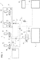
- Figure 1 discloses a gas distribution circuit 1 for feeding a gas engine 2 of a work vehicle, e.g. a tractor (not shown), according to a first embodiment of the invention.
- Gas distribution circuit 1 comprises a main tank module 3 for storing gas in compressed/liquid phase; in the disclosed embodiment circuit 1 comprises two main tanks 3a, 3b fluidly connectable to engine 2 as disclosed in the following.
- first and second main tanks 3a, 3b are fluidly connected together by respective conduits 4a, 4b which joins into a common conduit 5 which is then fluidly connectable to engine 2.
- circuit 1 comprises, on each main tank 3a, 3b on the respective conduits 4a, 4b a valve 6a, 6b configured to allows passage of gas between main tanks 3a, 3b and conduit 5 or only in the direction directed to tanks 3a, 3b.
- valves 6a, 6b are two ways - two position valves and, preferably, electro-mechanically actuated valves, according to R110 EU requirements.
- Circuit 1 further comprises a check valve 7 fluidly interposed on conduit 5 between conduits 4a, 4b and engine 2 and configured to allow the passage of gas only from tanks 3a, 3b to engine 2.
- Conduit 5 is furthermore fluidly connected via a filling conduit 8 to a filing port 9 configured to allow filling of main tank module 3.
- Filling port 9 may be of any known typology and therefore it is not described for sake of brevity.
- Circuit 1 further comprises a check valve 11 fluidly interposed on filling conduit 8 and configured to allow the passage of gas only from filling port 9 towards main tank module 3.
- Gas distribution circuit 1 is configured to allow the coupling of an auxiliary tank module 12 for storing gas in compressed/liquid phase; in the disclosed embodiment circuit 1 comprises two auxiliary tanks 12a, 12b fluidly connectable to engine 2 as disclosed in the following.
- first and second auxiliary tanks 12a, 12b are fluidly connected together by respective conduits 13a, 13b which joins into a common conduit 14 which is then fluidly connectable to engine 2.
- circuit 1 comprises, on each auxiliary tank 12a, 12b on the respective conduits 13a, 13b a valve 15a, 15b configured to allows passage of gas between auxiliary tanks 12a, 12b and conduit 14 or only in the direction directed to tanks 12a, 12b.
- valves 15a, 15b are two ways - two position valves and, preferably, electro-mechanically actuated valves according to R110 EU requirements.
- Circuit 1 comprises a conduit 16 fluidly connecting engine 2 and provided with a coupling interface 17 configured to selectively fluidly connect conduit 14 with conduit 16.
- coupling interface 17 may be of any typology, e.g. comprising a quick coupler and a flexible hose, and herein not described for sake of brevity.
- Conduit 16 is furthermore fluidly connected to filling port 9 via a conduit 18 joint to conduit 16 downstream with respect to coupling interface 17.
- circuit 1 comprises a check valve 19 fluidly interposed on conduit 18 and configured to allow the passage of gas only from filling port 9 towards auxiliary tank module 12.
- circuit 1 comprises a check valve 21 fluidly interposed on conduit 16 upstream with respect to engine 2 and downstream with respect to junction of conduit 18 with conduit 16.
- Check valve 21 is configured to allow the passage of gas only from auxiliary tanks 12a, 12b towards engine 2.
- circuit 1 comprises a valve 22 configured to allow or deny the passage of gas from main tank module 3 towards engine 2 according to the pressure of gas coming from auxiliary tank module in conduit 16.
- valve 22 is a two ways - two positions pressure actuated valve configured to assume a first position into which it allows gas communication between engine 2 and conduit 5 or a second position into which denies gas communication between these latter elements.
- valve 22 is balanced by an elastic element 23 determining a preset threshold under which valve 22 is maintained into the above mentioned first position.
- a preset threshold may be varied and set according to user's settings. More preferably such threshold may be set as 40 bar.
- auxiliary tanks 12a, 12b The force applied by elastic element 23 is balanced by a pilot signal 24 taken from conduit 16, i.e. representing the pressure of gas into auxiliary tanks 12a, 12b. Accordingly, if pressure into these latter is lower, valve 22 allows fluidic communication from main tanks 3a, 3b, otherwise fluidic communication from main tanks 3a, 3b is denied and engine 2 is feed by auxiliary tanks 12a, 12b.
- Circuit 1 may further comprise a pressure sensor 25 configured to detect pressure on conduit 16 and connected to an indicator 26 suitable for indicating the fuel level on auxiliary tank module 12.
- indicator 26 is an electrical indicator and is electrically connected to pressure sensor 25.
- Circuit 1 may further comprise aN electronic control unit 27 configured to monitor and control electrical elements of circuit 1.
- control unit 27 is electrically connected to indicator 26 and to valves 6a, 6b and 15a 15b respectively to monitor acquired pressure data or to allow their position switch.
- a first working mode i.e. gas distribution to engine mode
- gas flows into conduit 16 through check valve 21 and then to engine 2.
- Check valve 19 deny the passage of gas to filling port 9.
- the pressure of gas inside conduit 16 is measured by sensor 25, displayed by indicator 26 and acquired by control unit 27. From conduit 16 pressure pilot signal 24 acts against force of elastic element 23 therefore maintaining valve 22 in its second position, i.e. denying flow passage from conduit 5 to engine 2.
- valve 22 switch position thereby allowing passage of gas from conduit 5 to engine 2.
- gas in conduit 5 do not pass in conduit 16 because of check valve 21.
- elastic element 23 will maintain valve 22 in its first position, i.e. allowing feeding of engine 2 by main tank module 3.
- gas will pass in conduits 8 and 18 towards main and auxiliary tank modules 3, 12 through the respective check valves 11 and 19 so as to allow their filling.
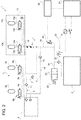
- Figure 2 discloses a gas distribution circuit 1 according to a second embodiment of the invention.
- Circuit of figure 2 comprises essentially the same elements of the circuit 1 as disclosed in the first embodiment, except for the fact that the system further comprises at least an emergency switch 28 configured to shutoff valves 6a, 6b, 15a, 15b of main and auxiliary tank modules 3, 12 so that no fluidic communication is possible to/from engine 2.
- Control unit 27 may take care of emergency switch activation, in known way.
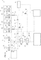
- Figure 3 discloses a gas distribution circuit 1 according to a third embodiment of the invention. Such embodiment is directed to implement the embodiment as described in figure 1 in case of more different auxiliary tank modules 12.
- gas distribution circuit 1 is configured to allow the coupling of two auxiliary tank modules 12', 12'' for storing gas in compressed/liquid phase; similarly to the first and second embodiments, modules 12', 12'' comprises each two tanks 12a', 12a", 12b', 12b'' fluidly connected together by respective conduits 13a', 13a'', 13b', 13b'' respectively joining into common conduits 14', 14'' which are each separately then fluidly connectable to engine 2.
- circuit 1 comprises, on auxiliary tanks 12a', 12a", 12b', 12b" a valve 15a', 15a", 15b', 15b” on the respective conduits and configured to allows passage of gas in between auxiliary tanks 12a', 12a", 12b', 12b" or only in the direction directed to these latter.
- valves are realized as described for the other embodiments.
- Circuit 1 comprises, for each auxiliary tank module 12 respective conduits 16', 16" fluidly connecting engine 2 and each provided with a coupling interface 17', 17" configured to selectively fluidly connect conduits 14', 14" with conduits 16', 16".
- coupling interface 17 may be of any typology.
- Each conduit 16', 16" is furthermore fluidly connected to a filling port 9 via a respective conduit 18', 18" joint to the respective conduit 16', 16" downstream with respect to coupling interface 17', 17".
- circuit 1 comprises a check valve 19', 19" respectively fluidly interposed on each conduit 18', 18" and configured to allow the passage of gas only from filling port 9 towards auxiliary tank modules 12', 12".
- circuit 1 comprises a check valve 21', 21" fluidly interposed on each conduit 16', 16" upstream with respect to engine 2 and downstream with respect to junction of conduits 18', 18" with the respective conduit 16', 16".
- Check valve 21 is configured to allow the passage of gas only from auxiliary modules 12', 12" towards engine 2.
- circuit 1 comprises a valve 22', 22" configured to allow or deny the passage of gas from main tank module 3 towards engine 2 according to the pressure of gas coming from auxiliary tank modules 12', 12" in conduits 16', 16".
- valves 22', 22' are a two ways- two positions pressure-actuated valve configured to assume a first position into which they allow gas communication between engine 2 and conduit 5 or a second position into which they deny gas communication between these latter elements.
- valves 22', 22" are each balanced by an elastic element 23', 23" determining preset thresholds under which valves 22', 22" are maintained into the above mentioned first positions. Preferably such thresholds may be varied and set according to user's settings.
- valves 22', 22" are fluidly connected in series so that the valve 22' related to first auxiliary tank module 12' is upstream with respect to valve 22" related to second auxiliary tank module 12".
- thresholds may differ with respect to the other, so that it is possible to allow first the fluid communication of second auxiliary tank module 12", then the fluid communication of first auxiliary tank module 12' and, then, fluid communication of main auxiliary tank module 3 towards engine 2.
- valve 22 allows fluidic communication between second auxiliary tank module 12" and engine 2, otherwise it is denied such communication and it is allowed fluidic communication between first auxiliary tank module 12' and engine 2 till pressure 24' is higher than the set threshold of valve 22'; otherwise, such communication is denied and the it is allowed fluidic communication between main tank module 3 and engine 2.
- circuit 1 may further comprise pressure sensors 25', 25" configured to detect pressure on conduit 16', 16" and an electronic control unit 27 configured to monitor and control electrical elements of circuit 1, i.e. indicator 26 and all valves of modules 3, 12' and 12" respectively to monitor acquired pressure data or to allow their position switch.
- a first working mode i.e. gas distribution to engine mode
- gas flows into conduit 16" from second auxiliary tank 12" through check valve 21" and then to engine 2.
- Check valve 19" deny the passage of gas to filling port 9.
- the pressure of gas inside conduit 16 is measured by sensor 25", displayed by indicator 26 and acquired by control unit 27. From conduit 16" pressure pilot signal 24" acts against force of elastic element 23" therefore maintaining valve 22" in its second position, i.e. denying flow passage from conduit 16' to engine 2.
- valve 22" switches position thereby allowing passage of gas from conduit 16', i.e. to first auxiliary tank module 12' to engine 2.
- gas in conduit 16' does not pass in conduit 16" because of check valve 21".
- no pressure pilot signal 24" would be present and accordingly elastic element 23" will maintain valve 22" in its first position, i.e. allowing feeding of engine 2 by first auxiliary module 12'.
- gas will pass in conduits 8, 18' and 18" towards main and first and second auxiliary tank modules 3, 12', 12" through the respective check valves 11, 19', 19" so as to allow their filling.
- Valve means 2 are simple, economic and versatile since the preset threshold may be varied according to user's setting.
- the proposed gas distribution circuit 1 is scalable, i.e. may be used without major modification with more than one auxiliary tank module 12. In such case, moreover, it is possible to set different pressure thresholds so as to discharge a single auxiliary tank module 12', 12" one by one.
- emergency switches 28 and indicator 26 allows respectively to lock the system in case of a fault, to monitor the value of the gas level in auxiliary tank module 12.
- the parallel use of a control unit 27 allows to monitor and control the aforementioned elements.
- both main and auxiliary tank modules 3, 12 can comprise different number of tanks 3a, 3b, 12a, 12b and number and typology of valves 6a, 6b, 15a, 15b.
- Valve means 22 may be substituted by equivalent valves with respect to the described one having the same functionality. Similar consideration may be applied to sensor means 25, indicator 26 and emergency switches 28.
- auxiliary tank modules 12', 12" may be varied and that pressure threshold may be set so as to obtain a parallel or an alternative feeding from such modules.
Landscapes
- Engineering & Computer Science (AREA)
- Mechanical Engineering (AREA)
- General Engineering & Computer Science (AREA)
- Filling Or Discharging Of Gas Storage Vessels (AREA)
Abstract
Description
- The present invention concerns a gas distribution circuit, in particular a gas distribution circuit for feeding a gas engine for a work vehicle.
- Tractors may be powered by using gas fuel in order to reduce the emissions with respect to other typology of fossil fuels.
- One example of gas fuel is Compressed Natural Gas (CNG) (methane stored at high pressure) that is a fuel which can be used in place of gasoline.
- Today the current design layout of a tractor does not allow to accommodate a main tank large enough for storing of a suitable amount of gas fuel to allow to power the engine for a full working day of the tractor. Accordingly, the tractor has to be used with an auxiliary gas tank that is carried by an auxiliary unit such as a towed implement or a range extender such as the front or rear hitch or fixed to the front on the front axle support.
- Usually such main tank is used first for feeding the gas engine and, when such tank is almost empty, the auxiliary tank is used for feeding the engine.
- However it may happen that main tank of the tractor has not sufficient gas for returning to its recovery, leaving its user in the fields without possibility of moving away.
- Further, implements or range extenders provided with gas tanks are not usually driven on roads because they may be not homologated for such configuration and therefore, if the auxiliary unit has the entire tank full of gas, it should be left on the fields leading to the danger of explosion in hot/sunny environment.
- In view of the above, the need is felt to foresee an optimized system for managing gas between a tractor and an auxiliary unit when such tractor uses gas for feeding its engine.
- Furthermore, European Regulation R110 concerning gas vehicles and gas arrangements for elements related to storing, distributing and using such gas imposes strict requirements to be accomplished by vehicle manufacturers. Exempli gratia, electrical actuation in circuit 1 should be avoided.
- Therefore, the need is felt to provide a system for distributing gas to a gas engine for a work vehicle which uses, in an optimized way, the gas contained in a plurality of tanks and which complies with R110 requirements.
- An aim of the present invention is to satisfy the above mentioned needs.
- The aforementioned aim is reached by a gas distribution circuit as claimed in the appended set of claims.
- For a better understanding of the present invention, a preferred embodiment is described in the following, by way of a non-limiting example, with reference to the attached drawings wherein:
-
Figure 1 is a gas distribution circuit for a gas engine according to a first embodiment of the present invention; -
Figure 2 is a gas distribution circuit for a gas engine according to a second embodiment of the present invention; and -
Figure 3 is a gas distribution circuit for a gas engine according to a third embodiment of the present invention. -
Figure 1 discloses a gas distribution circuit 1 for feeding agas engine 2 of a work vehicle, e.g. a tractor (not shown), according to a first embodiment of the invention. - Gas distribution circuit 1 comprises a main tank module 3 for storing gas in compressed/liquid phase; in the disclosed embodiment circuit 1 comprises two
main tanks engine 2 as disclosed in the following. - According to the described embodiment, first and second
main tanks respective conduits common conduit 5 which is then fluidly connectable toengine 2. - In greater particular, circuit 1 comprises, on each
main tank respective conduits valve main tanks conduit 5 or only in the direction directed totanks such valves - Circuit 1 further comprises a check valve 7 fluidly interposed on
conduit 5 betweenconduits engine 2 and configured to allow the passage of gas only fromtanks engine 2. -
Conduit 5 is furthermore fluidly connected via a fillingconduit 8 to afiling port 9 configured to allow filling of main tank module 3. Fillingport 9 may be of any known typology and therefore it is not described for sake of brevity. Circuit 1 further comprises acheck valve 11 fluidly interposed on fillingconduit 8 and configured to allow the passage of gas only from fillingport 9 towards main tank module 3. - Gas distribution circuit 1 is configured to allow the coupling of an
auxiliary tank module 12 for storing gas in compressed/liquid phase; in the disclosed embodiment circuit 1 comprises twoauxiliary tanks engine 2 as disclosed in the following. - According to the described embodiment, first and second
auxiliary tanks respective conduits common conduit 14 which is then fluidly connectable toengine 2. - In greater particular, circuit 1 comprises, on each
auxiliary tank respective conduits valve auxiliary tanks conduit 14 or only in the direction directed totanks such valves - Circuit 1 comprises a
conduit 16 fluidly connectingengine 2 and provided with acoupling interface 17 configured to selectively fluidly connectconduit 14 withconduit 16. In particular,coupling interface 17 may be of any typology, e.g. comprising a quick coupler and a flexible hose, and herein not described for sake of brevity. -
Conduit 16 is furthermore fluidly connected to fillingport 9 via aconduit 18 joint to conduit 16 downstream with respect tocoupling interface 17. In particular, circuit 1 comprises acheck valve 19 fluidly interposed onconduit 18 and configured to allow the passage of gas only from fillingport 9 towardsauxiliary tank module 12. - Advantageously, circuit 1 comprises a
check valve 21 fluidly interposed onconduit 16 upstream with respect toengine 2 and downstream with respect to junction ofconduit 18 withconduit 16.Check valve 21 is configured to allow the passage of gas only fromauxiliary tanks engine 2. - Advantageously, circuit 1 comprises a
valve 22 configured to allow or deny the passage of gas from main tank module 3 towardsengine 2 according to the pressure of gas coming from auxiliary tank module inconduit 16. - According to the described embodiment,
valve 22 is a two ways - two positions pressure actuated valve configured to assume a first position into which it allows gas communication betweenengine 2 andconduit 5 or a second position into which denies gas communication between these latter elements. - In greater detail,
valve 22 is balanced by anelastic element 23 determining a preset threshold under whichvalve 22 is maintained into the above mentioned first position. Preferably such threshold may be varied and set according to user's settings. More preferably such threshold may be set as 40 bar. - The force applied by
elastic element 23 is balanced by apilot signal 24 taken fromconduit 16, i.e. representing the pressure of gas intoauxiliary tanks valve 22 allows fluidic communication frommain tanks main tanks engine 2 is feed byauxiliary tanks - Circuit 1 may further comprise a
pressure sensor 25 configured to detect pressure onconduit 16 and connected to anindicator 26 suitable for indicating the fuel level onauxiliary tank module 12. Advantageously,indicator 26 is an electrical indicator and is electrically connected topressure sensor 25. - Circuit 1 may further comprise aN
electronic control unit 27 configured to monitor and control electrical elements of circuit 1. According to the described embodiment,control unit 27 is electrically connected toindicator 26 and tovalves 15a 15b respectively to monitor acquired pressure data or to allow their position switch. - The operation of the above disclosed embodiment is the following.
- In a first working mode, i.e. gas distribution to engine mode, supposing that
auxiliary tank module 12 is attached toconduit 16, gas flows intoconduit 16 throughcheck valve 21 and then toengine 2. Checkvalve 19 deny the passage of gas to fillingport 9. The pressure of gas insideconduit 16 is measured bysensor 25, displayed byindicator 26 and acquired bycontrol unit 27. Fromconduit 16pressure pilot signal 24 acts against force ofelastic element 23 therefore maintainingvalve 22 in its second position, i.e. denying flow passage fromconduit 5 toengine 2. - The above configuration is maintained till pressure in
conduit 16 is above the pressure threshold given by force ofelastic element 23. Once passed below such threshold,valve 22 switch position thereby allowing passage of gas fromconduit 5 toengine 2. In parallel, gas inconduit 5 do not pass inconduit 16 because ofcheck valve 21. The same situation occurs in case noauxiliary tank module 12 is present. Indeed, nopressure pilot signal 24 would be present and accordinglyelastic element 23 will maintainvalve 22 in its first position, i.e. allowing feeding ofengine 2 by main tank module 3. - In a second working mode, i.e. filling tank mode, gas will pass in
conduits auxiliary tank modules 3, 12 through therespective check valves -
Figure 2 discloses a gas distribution circuit 1 according to a second embodiment of the invention. - Circuit of
figure 2 comprises essentially the same elements of the circuit 1 as disclosed in the first embodiment, except for the fact that the system further comprises at least anemergency switch 28 configured toshutoff valves auxiliary tank modules 3, 12 so that no fluidic communication is possible to/fromengine 2. - The operation of the above mentioned embodiment is the same of the first embodiment, except for the fact that, if a fault occurs in
engine 2 or in other vehicle elements or in circuit 1,valves Control unit 27 may take care of emergency switch activation, in known way. -
Figure 3 discloses a gas distribution circuit 1 according to a third embodiment of the invention. Such embodiment is directed to implement the embodiment as described infigure 1 in case of more differentauxiliary tank modules 12. - In the describe alternative embodiment, gas distribution circuit 1 is configured to allow the coupling of two auxiliary tank modules 12', 12'' for storing gas in compressed/liquid phase; similarly to the first and second embodiments, modules 12', 12'' comprises each two
tanks 12a', 12a", 12b', 12b'' fluidly connected together byrespective conduits 13a', 13a'', 13b', 13b'' respectively joining into common conduits 14', 14'' which are each separately then fluidly connectable toengine 2. - Always similarly to what described to the other embodiments, circuit 1 comprises, on
auxiliary tanks 12a', 12a", 12b', 12b" avalve 15a', 15a", 15b', 15b" on the respective conduits and configured to allows passage of gas in betweenauxiliary tanks 12a', 12a", 12b', 12b" or only in the direction directed to these latter. Preferably such valves are realized as described for the other embodiments. - Circuit 1 comprises, for each
auxiliary tank module 12respective conduits 16', 16" fluidly connectingengine 2 and each provided with acoupling interface 17', 17" configured to selectively fluidly connectconduits 14', 14" withconduits 16', 16". As said for the other embodiments,coupling interface 17 may be of any typology. - Each
conduit 16', 16" is furthermore fluidly connected to a fillingport 9 via arespective conduit 18', 18" joint to therespective conduit 16', 16" downstream with respect tocoupling interface 17', 17". In particular, circuit 1 comprises acheck valve 19', 19" respectively fluidly interposed on eachconduit 18', 18" and configured to allow the passage of gas only from fillingport 9 towardsauxiliary tank modules 12', 12". - Advantageously, circuit 1 comprises a
check valve 21', 21" fluidly interposed on eachconduit 16', 16" upstream with respect toengine 2 and downstream with respect to junction ofconduits 18', 18" with therespective conduit 16', 16". Checkvalve 21 is configured to allow the passage of gas only fromauxiliary modules 12', 12" towardsengine 2. - Advantageously, circuit 1 comprises a
valve 22', 22" configured to allow or deny the passage of gas from main tank module 3 towardsengine 2 according to the pressure of gas coming fromauxiliary tank modules 12', 12" inconduits 16', 16". - Similarly to the other described embodiments, valves 22', 22' are a two ways- two positions pressure-actuated valve configured to assume a first position into which they allow gas communication between
engine 2 andconduit 5 or a second position into which they deny gas communication between these latter elements. Similarly,valves 22', 22" are each balanced by anelastic element 23', 23" determining preset thresholds under whichvalves 22', 22" are maintained into the above mentioned first positions. Preferably such thresholds may be varied and set according to user's settings. - In particular,
valves 22', 22" are fluidly connected in series so that the valve 22' related to first auxiliary tank module 12' is upstream with respect tovalve 22" related to secondauxiliary tank module 12". - More preferably such thresholds may differ with respect to the other, so that it is possible to allow first the fluid communication of second
auxiliary tank module 12", then the fluid communication of first auxiliary tank module 12' and, then, fluid communication of main auxiliary tank module 3 towardsengine 2. - The force applied by
elastic element 23', 23" is balanced by arespective pilot signal 24', 24" taken from therelated conduit 16', 16", i.e. representing the pressure of gas intoauxiliary tank modules 12', 12". Accordingly, if pressure conduit 16'' is higher than the set threshold ofvalve 22",valve 22" allows fluidic communication between secondauxiliary tank module 12" andengine 2, otherwise it is denied such communication and it is allowed fluidic communication between first auxiliary tank module 12' andengine 2 till pressure 24' is higher than the set threshold of valve 22'; otherwise, such communication is denied and the it is allowed fluidic communication between main tank module 3 andengine 2. - According to the above disclosed structure, circuit 1 may further comprise
pressure sensors 25', 25" configured to detect pressure onconduit 16', 16" and anelectronic control unit 27 configured to monitor and control electrical elements of circuit 1, i.e.indicator 26 and all valves ofmodules 3, 12' and 12" respectively to monitor acquired pressure data or to allow their position switch. - The operation of the above disclosed embodiment is the following.
- In a first working mode, i.e. gas distribution to engine mode, supposing that
auxiliary tank modules 12', 12" are attached toconduit 16', 16", then gas flows intoconduit 16" from secondauxiliary tank 12" throughcheck valve 21" and then toengine 2. Checkvalve 19" deny the passage of gas to fillingport 9. The pressure of gas insideconduit 16 is measured bysensor 25", displayed byindicator 26 and acquired bycontrol unit 27. Fromconduit 16"pressure pilot signal 24" acts against force ofelastic element 23" therefore maintainingvalve 22" in its second position, i.e. denying flow passage from conduit 16' toengine 2. - The above configuration is maintained till pressure in
conduit 16" is above the pressure threshold given by force ofelastic element 23". Once passed below such threshold,valve 22" switches position thereby allowing passage of gas from conduit 16', i.e. to first auxiliary tank module 12' toengine 2. In parallel, gas in conduit 16' does not pass inconduit 16" because ofcheck valve 21". The same situation occurs in case no second auxiliary tank module 12'' is present. Indeed, nopressure pilot signal 24" would be present and accordinglyelastic element 23" will maintainvalve 22" in its first position, i.e. allowing feeding ofengine 2 by first auxiliary module 12'. - Then, the operation is the same as described in the first embodiment, into which gas from first auxiliary tank module 12' flows to
engine 2 till pressure on conduit 16' is higher than the pressure threshold of valve 22', otherwise gas will flow from main tank module 3, as already described and not repeated for sake of brevity. - In a second working mode, i.e. filling tank mode, gas will pass in
conduits auxiliary tank modules 3, 12', 12" through therespective check valves - In view of the foregoing, the advantages of a gas distribution circuit 1 according to the invention are apparent.
- First, it is possible to automatically control the feeding of gas to
engine 2 selecting first theauxiliary tank module 12 and, then, main tank module 3 without incurring in an electrical control. - Valve means 2 are simple, economic and versatile since the preset threshold may be varied according to user's setting.
- Furthermore, the proposed gas distribution circuit 1 is scalable, i.e. may be used without major modification with more than one
auxiliary tank module 12. In such case, moreover, it is possible to set different pressure thresholds so as to discharge a singleauxiliary tank module 12', 12" one by one. - It is furthermore possible to use the same filling
port 9 to refill both main andauxiliary tank modules 3, 12 in a quick way. - Further the presence of emergency switches 28 and
indicator 26 allows respectively to lock the system in case of a fault, to monitor the value of the gas level inauxiliary tank module 12. The parallel use of acontrol unit 27 allows to monitor and control the aforementioned elements. - It is clear that modifications can be made to the described gas distribution circuit 1 which do not extend beyond the scope of protection defined by the claims.
- For example, both main and
auxiliary tank modules 3, 12 can comprise different number oftanks valves - Valve means 22 may be substituted by equivalent valves with respect to the described one having the same functionality. Similar consideration may be applied to sensor means 25,
indicator 26 and emergency switches 28. - It is clear that number of
auxiliary tank modules 12', 12" may be varied and that pressure threshold may be set so as to obtain a parallel or an alternative feeding from such modules.
Claims (17)
- Gas distribution circuit (1) for feeding a gas engine (2) of a work vehicle, said gas distribution circuit (1) comprising a main tank module (3) and being configured to be in fluid communication with at least one auxiliary tank module (12), said main tank module (3) being fluidly connected to said engine via a first conduit (5) and said at least one auxiliary tank module (12) being connectable to said engine via a second conduit (16), said gas distribution circuit (1) comprising valve means (22) fluidly interposed on said first conduit (5) and configured to allow or deny gas communication between said main tank module (3) and said engine (2), said valve means (22) allowing such fluid communication if pressure in said second conduit (16) is higher than a preset threshold, otherwise, fluid communication is allowed only between said at least one auxiliary tank module (12) and said engine (2).
- Gas distribution circuit according to claim 1, wherein said valve means (22) comprises a two ways - two positions pressure actuated valve.
- Gas distribution circuit according to claim 1 or 2, wherein said preset threshold is variable.
- Gas distribution circuit according to any of the preceding claims, wherein said valve means (22) are configured to allow or deny said fluid communication according to a balance between a first pressure force given by elastic means (23) acting on said valve means (22) and a second pressure force given by a pressure pilot signal (24) taken from said second conduit (16).
- Gas distribution circuit according to any of the preceding claims, further comprising a check valve (21) fluidly interposed on said second conduit (16) configured to allow passage of gas only from said auxiliary tank unit (12) to said engine (2).
- Gas distribution circuit according to any of the preceding claims, further comprising a check valve (7) fluidly interposed on said first conduit (5) configured to allow passage of gas only from said main tank unit (3) to said engine (2) .
- Gas distribution circuit according to any of the preceding claims, comprising a first auxiliary tank module (12') and at least a second auxiliary tank module (12"), said first and second auxiliary tank module (12', 12") being connectable to said engine (2) via respective second conduits (16', 16"), said circuit (1) comprises respectively valve means (22', 22') on said first conduit (5), said valve means (22', 22') allowing said fluid communication if pressure in said second conduits (16', 16") is higher than respective preset thresholds.
- Gas distribution circuit according to claim 7, wherein the preset thresholds of said valve means (22', 22") are different.
- Gas distribution circuit according to claim 7 or 8, wherein the preset threshold of the second auxiliary tank module (12") is higher than the preset threshold of the first auxiliary tank module (12').
- Gas distribution circuit according to any of the preceding claims, further comprising a filling port (9) fluidly connected to said first and second conduits (5, 16) via respective conduit (8, 18) provided with check valves (11, 19), each configured to allow the passage of gas only from said filling port (9) towards said conduits (5, 16).
- Gas distribution circuit according to any of the preceding claims, further comprising at least one coupling interface (17, 17', 17") configured to fluidly connect second conduit (16, 16', 16") to said at least one auxiliary tank module (12, 12', 12").
- Gas distribution circuit according to any of the preceding claims, wherein said main tank module (3) and said at least one auxiliary tank module (12, 12'', 12") each comprises a plurality of tanks (3a, 3b, 12a, 12b, 12a', 12b', 12a", 12b") fluidly connected together.
- Gas distribution circuit according to any of the preceding claims, wherein said main and said at least one auxiliary tank module (3, 12, 12'', 12") each comprises valve means (6a, 6b, 15a, 15b, 15a', 15b', 15a", 15b") configured to either allow fluidic communication between at least one tank (3a, 3b, 12a, 12b, 12a', 12b', 12a", 12b") and the respective first and second conduits (5, 16, 16', 16") or allow fluidic communication only towards said at least one tank (3a, 3b, 12a, 12b, 12a', 12b', 12a", 12b").
- Gas distribution circuit according to claim 13, wherein said valve means (6a, 6b, 15a, 15b, 15a', 15b', 15a", 15b") are electro-mechanical actuated valves.
- Gas distribution circuit according any of the preceding claims, comprising emergency switch means (28) configured to lock the communication from said main and auxiliary tanks (3, 12) towards said engine (2).
- Gas distribution circuit according any of the preceding claims, comprising sensor means (25, 25', 25") configured to detect a pressure value in said second conduit (16, 16', 16") and an indicator (26) configured to display such pressure value.
- Gas distribution circuit according any claims 13 to 16, further comprising an electronic control unit (27) electrically connected to the electrical components of said circuits and configured to monitor and/or to control their operation.
Applications Claiming Priority (1)
| Application Number | Priority Date | Filing Date | Title |
|---|---|---|---|
| IT201900007112 | 2019-05-22 |
Publications (2)
| Publication Number | Publication Date |
|---|---|
| EP3742039A1 true EP3742039A1 (en) | 2020-11-25 |
| EP3742039B1 EP3742039B1 (en) | 2023-05-10 |
Family
ID=67734778
Family Applications (1)
| Application Number | Title | Priority Date | Filing Date |
|---|---|---|---|
| EP20175881.0A Active EP3742039B1 (en) | 2019-05-22 | 2020-05-21 | Gas distribution circuit for feeding a gas engine of a work vehicle |
Country Status (1)
| Country | Link |
|---|---|
| EP (1) | EP3742039B1 (en) |
Citations (4)
| Publication number | Priority date | Publication date | Assignee | Title |
|---|---|---|---|---|
| US5014733A (en) * | 1990-06-14 | 1991-05-14 | Wilson Earl L | Automatic switching valve |
| US20060118175A1 (en) * | 2004-12-02 | 2006-06-08 | Mathison Steven R | Hydrogen vehicle gas utilization and refueling system |
| US20090283351A1 (en) * | 2004-08-12 | 2009-11-19 | Gilles Cannet | Gas storage system, method using same, and vehicle incorporating same |
| US8539972B2 (en) * | 2007-07-12 | 2013-09-24 | Beijing Bolken Equipment Corporation | Low consumption and intelligent safe gas-supply system using gas tanks |
-
2020
- 2020-05-21 EP EP20175881.0A patent/EP3742039B1/en active Active
Patent Citations (4)
| Publication number | Priority date | Publication date | Assignee | Title |
|---|---|---|---|---|
| US5014733A (en) * | 1990-06-14 | 1991-05-14 | Wilson Earl L | Automatic switching valve |
| US20090283351A1 (en) * | 2004-08-12 | 2009-11-19 | Gilles Cannet | Gas storage system, method using same, and vehicle incorporating same |
| US20060118175A1 (en) * | 2004-12-02 | 2006-06-08 | Mathison Steven R | Hydrogen vehicle gas utilization and refueling system |
| US8539972B2 (en) * | 2007-07-12 | 2013-09-24 | Beijing Bolken Equipment Corporation | Low consumption and intelligent safe gas-supply system using gas tanks |
Also Published As
| Publication number | Publication date |
|---|---|
| EP3742039B1 (en) | 2023-05-10 |
Similar Documents
| Publication | Publication Date | Title |
|---|---|---|
| RU2659344C2 (en) | Vehicle with coupling device for mounting attachments and mounting attachment for said vehicle | |
| US4574904A (en) | Auxilliary steering system | |
| US7426935B2 (en) | Method of discharging high pressure storage vessels | |
| US20180112686A1 (en) | Hydraulic actuator system of vehicle having secondary load-holding valve with tank connection | |
| US8720485B2 (en) | Fuel system including dual fuel delivery modules for bifurcated fuel tanks | |
| CN111032456A (en) | Electropneumatic trailer supply module for providing a trailer supply pressure | |
| US20130139498A1 (en) | Control apparatus for a first tool and a second tool | |
| JP2015058768A (en) | On-vehicle system and wire harness structure | |
| US20130312401A1 (en) | Pilot Pressure Supply System | |
| US20030188529A1 (en) | Hydraulic system architecture for controlling steering | |
| JP2016161071A (en) | Hydrogen filling system | |
| EP3742039B1 (en) | Gas distribution circuit for feeding a gas engine of a work vehicle | |
| CN104074809B (en) | Hydraulic system | |
| US11168710B2 (en) | Control apparatus for supplying at least one hydraulic consumer with fluid | |
| US8899627B2 (en) | Multiple fuel tank system | |
| EP3994020A1 (en) | A fuel gas system for a vehicle | |
| US20200182268A1 (en) | Pressure supply device | |
| US20070169473A1 (en) | Hydraulic circuit | |
| US20110277460A1 (en) | Electrohydraulic Steering System | |
| CN102345518A (en) | Multi-circuit fuel supply (diesel fuel) control circuit for vehicle | |
| US10822025B1 (en) | Hydraulic valve module for steering and work functions in a work vehicle | |
| WO2021209876A1 (en) | Tank unit for a hydrogen fuel cell automotive system | |
| EP3121078B1 (en) | Modular air supply control system | |
| CN204163902U (en) | Engine system | |
| EP4083444A1 (en) | Hydraulic circuit for an agricultural vehicle provided with an anti-saturation system and anti-saturation control method |
Legal Events
| Date | Code | Title | Description |
|---|---|---|---|
| PUAI | Public reference made under article 153(3) epc to a published international application that has entered the european phase |
Free format text: ORIGINAL CODE: 0009012 |
|
| STAA | Information on the status of an ep patent application or granted ep patent |
Free format text: STATUS: THE APPLICATION HAS BEEN PUBLISHED |
|
| AK | Designated contracting states |
Kind code of ref document: A1 Designated state(s): AL AT BE BG CH CY CZ DE DK EE ES FI FR GB GR HR HU IE IS IT LI LT LU LV MC MK MT NL NO PL PT RO RS SE SI SK SM TR |
|
| AX | Request for extension of the european patent |
Extension state: BA ME |
|
| STAA | Information on the status of an ep patent application or granted ep patent |
Free format text: STATUS: REQUEST FOR EXAMINATION WAS MADE |
|
| 17P | Request for examination filed |
Effective date: 20210525 |
|
| RBV | Designated contracting states (corrected) |
Designated state(s): AL AT BE BG CH CY CZ DE DK EE ES FI FR GB GR HR HU IE IS IT LI LT LU LV MC MK MT NL NO PL PT RO RS SE SI SK SM TR |
|
| GRAP | Despatch of communication of intention to grant a patent |
Free format text: ORIGINAL CODE: EPIDOSNIGR1 |
|
| STAA | Information on the status of an ep patent application or granted ep patent |
Free format text: STATUS: GRANT OF PATENT IS INTENDED |
|
| INTG | Intention to grant announced |
Effective date: 20221129 |
|
| GRAS | Grant fee paid |
Free format text: ORIGINAL CODE: EPIDOSNIGR3 |
|
| GRAA | (expected) grant |
Free format text: ORIGINAL CODE: 0009210 |
|
| STAA | Information on the status of an ep patent application or granted ep patent |
Free format text: STATUS: THE PATENT HAS BEEN GRANTED |
|
| AK | Designated contracting states |
Kind code of ref document: B1 Designated state(s): AL AT BE BG CH CY CZ DE DK EE ES FI FR GB GR HR HU IE IS IT LI LT LU LV MC MK MT NL NO PL PT RO RS SE SI SK SM TR |
|
| REG | Reference to a national code |
Ref country code: GB Ref legal event code: FG4D |
|
| REG | Reference to a national code |
Ref country code: AT Ref legal event code: REF Ref document number: 1566974 Country of ref document: AT Kind code of ref document: T Effective date: 20230515 Ref country code: CH Ref legal event code: EP |
|
| REG | Reference to a national code |
Ref country code: DE Ref legal event code: R096 Ref document number: 602020010615 Country of ref document: DE |
|
| REG | Reference to a national code |
Ref country code: IE Ref legal event code: FG4D |
|
| P01 | Opt-out of the competence of the unified patent court (upc) registered |
Effective date: 20230411 |
|
| RAP4 | Party data changed (patent owner data changed or rights of a patent transferred) |
Owner name: CNH INDUSTRIAL ITALIA S.P.A. |
|
| REG | Reference to a national code |
Ref country code: LT Ref legal event code: MG9D |
|
| REG | Reference to a national code |
Ref country code: NL Ref legal event code: MP Effective date: 20230510 |
|
| REG | Reference to a national code |
Ref country code: AT Ref legal event code: MK05 Ref document number: 1566974 Country of ref document: AT Kind code of ref document: T Effective date: 20230510 |
|
| PG25 | Lapsed in a contracting state [announced via postgrant information from national office to epo] |
Ref country code: SE Free format text: LAPSE BECAUSE OF FAILURE TO SUBMIT A TRANSLATION OF THE DESCRIPTION OR TO PAY THE FEE WITHIN THE PRESCRIBED TIME-LIMIT Effective date: 20230510 Ref country code: PT Free format text: LAPSE BECAUSE OF FAILURE TO SUBMIT A TRANSLATION OF THE DESCRIPTION OR TO PAY THE FEE WITHIN THE PRESCRIBED TIME-LIMIT Effective date: 20230911 Ref country code: NO Free format text: LAPSE BECAUSE OF FAILURE TO SUBMIT A TRANSLATION OF THE DESCRIPTION OR TO PAY THE FEE WITHIN THE PRESCRIBED TIME-LIMIT Effective date: 20230810 Ref country code: NL Free format text: LAPSE BECAUSE OF FAILURE TO SUBMIT A TRANSLATION OF THE DESCRIPTION OR TO PAY THE FEE WITHIN THE PRESCRIBED TIME-LIMIT Effective date: 20230510 Ref country code: ES Free format text: LAPSE BECAUSE OF FAILURE TO SUBMIT A TRANSLATION OF THE DESCRIPTION OR TO PAY THE FEE WITHIN THE PRESCRIBED TIME-LIMIT Effective date: 20230510 Ref country code: AT Free format text: LAPSE BECAUSE OF FAILURE TO SUBMIT A TRANSLATION OF THE DESCRIPTION OR TO PAY THE FEE WITHIN THE PRESCRIBED TIME-LIMIT Effective date: 20230510 |
|
| PG25 | Lapsed in a contracting state [announced via postgrant information from national office to epo] |
Ref country code: RS Free format text: LAPSE BECAUSE OF FAILURE TO SUBMIT A TRANSLATION OF THE DESCRIPTION OR TO PAY THE FEE WITHIN THE PRESCRIBED TIME-LIMIT Effective date: 20230510 Ref country code: PL Free format text: LAPSE BECAUSE OF FAILURE TO SUBMIT A TRANSLATION OF THE DESCRIPTION OR TO PAY THE FEE WITHIN THE PRESCRIBED TIME-LIMIT Effective date: 20230510 Ref country code: LV Free format text: LAPSE BECAUSE OF FAILURE TO SUBMIT A TRANSLATION OF THE DESCRIPTION OR TO PAY THE FEE WITHIN THE PRESCRIBED TIME-LIMIT Effective date: 20230510 Ref country code: LT Free format text: LAPSE BECAUSE OF FAILURE TO SUBMIT A TRANSLATION OF THE DESCRIPTION OR TO PAY THE FEE WITHIN THE PRESCRIBED TIME-LIMIT Effective date: 20230510 Ref country code: IS Free format text: LAPSE BECAUSE OF FAILURE TO SUBMIT A TRANSLATION OF THE DESCRIPTION OR TO PAY THE FEE WITHIN THE PRESCRIBED TIME-LIMIT Effective date: 20230910 Ref country code: HR Free format text: LAPSE BECAUSE OF FAILURE TO SUBMIT A TRANSLATION OF THE DESCRIPTION OR TO PAY THE FEE WITHIN THE PRESCRIBED TIME-LIMIT Effective date: 20230510 Ref country code: GR Free format text: LAPSE BECAUSE OF FAILURE TO SUBMIT A TRANSLATION OF THE DESCRIPTION OR TO PAY THE FEE WITHIN THE PRESCRIBED TIME-LIMIT Effective date: 20230811 |
|
| PG25 | Lapsed in a contracting state [announced via postgrant information from national office to epo] |
Ref country code: FI Free format text: LAPSE BECAUSE OF FAILURE TO SUBMIT A TRANSLATION OF THE DESCRIPTION OR TO PAY THE FEE WITHIN THE PRESCRIBED TIME-LIMIT Effective date: 20230510 |
|
| REG | Reference to a national code |
Ref country code: CH Ref legal event code: PL |
|
| PG25 | Lapsed in a contracting state [announced via postgrant information from national office to epo] |
Ref country code: SK Free format text: LAPSE BECAUSE OF FAILURE TO SUBMIT A TRANSLATION OF THE DESCRIPTION OR TO PAY THE FEE WITHIN THE PRESCRIBED TIME-LIMIT Effective date: 20230510 |
|
| REG | Reference to a national code |
Ref country code: BE Ref legal event code: MM Effective date: 20230531 |
|
| PG25 | Lapsed in a contracting state [announced via postgrant information from national office to epo] |
Ref country code: SM Free format text: LAPSE BECAUSE OF FAILURE TO SUBMIT A TRANSLATION OF THE DESCRIPTION OR TO PAY THE FEE WITHIN THE PRESCRIBED TIME-LIMIT Effective date: 20230510 Ref country code: SK Free format text: LAPSE BECAUSE OF FAILURE TO SUBMIT A TRANSLATION OF THE DESCRIPTION OR TO PAY THE FEE WITHIN THE PRESCRIBED TIME-LIMIT Effective date: 20230510 Ref country code: RO Free format text: LAPSE BECAUSE OF FAILURE TO SUBMIT A TRANSLATION OF THE DESCRIPTION OR TO PAY THE FEE WITHIN THE PRESCRIBED TIME-LIMIT Effective date: 20230510 Ref country code: LU Free format text: LAPSE BECAUSE OF NON-PAYMENT OF DUE FEES Effective date: 20230521 Ref country code: LI Free format text: LAPSE BECAUSE OF NON-PAYMENT OF DUE FEES Effective date: 20230531 Ref country code: EE Free format text: LAPSE BECAUSE OF FAILURE TO SUBMIT A TRANSLATION OF THE DESCRIPTION OR TO PAY THE FEE WITHIN THE PRESCRIBED TIME-LIMIT Effective date: 20230510 Ref country code: DK Free format text: LAPSE BECAUSE OF FAILURE TO SUBMIT A TRANSLATION OF THE DESCRIPTION OR TO PAY THE FEE WITHIN THE PRESCRIBED TIME-LIMIT Effective date: 20230510 Ref country code: CZ Free format text: LAPSE BECAUSE OF FAILURE TO SUBMIT A TRANSLATION OF THE DESCRIPTION OR TO PAY THE FEE WITHIN THE PRESCRIBED TIME-LIMIT Effective date: 20230510 Ref country code: CH Free format text: LAPSE BECAUSE OF NON-PAYMENT OF DUE FEES Effective date: 20230531 |
|
| REG | Reference to a national code |
Ref country code: DE Ref legal event code: R097 Ref document number: 602020010615 Country of ref document: DE |
|
| PG25 | Lapsed in a contracting state [announced via postgrant information from national office to epo] |
Ref country code: MC Free format text: LAPSE BECAUSE OF FAILURE TO SUBMIT A TRANSLATION OF THE DESCRIPTION OR TO PAY THE FEE WITHIN THE PRESCRIBED TIME-LIMIT Effective date: 20230510 |
|
| REG | Reference to a national code |
Ref country code: IE Ref legal event code: MM4A |
|
| PG25 | Lapsed in a contracting state [announced via postgrant information from national office to epo] |
Ref country code: MC Free format text: LAPSE BECAUSE OF FAILURE TO SUBMIT A TRANSLATION OF THE DESCRIPTION OR TO PAY THE FEE WITHIN THE PRESCRIBED TIME-LIMIT Effective date: 20230510 |
|
| PLBE | No opposition filed within time limit |
Free format text: ORIGINAL CODE: 0009261 |
|
| STAA | Information on the status of an ep patent application or granted ep patent |
Free format text: STATUS: NO OPPOSITION FILED WITHIN TIME LIMIT |
|
| PG25 | Lapsed in a contracting state [announced via postgrant information from national office to epo] |
Ref country code: IE Free format text: LAPSE BECAUSE OF NON-PAYMENT OF DUE FEES Effective date: 20230521 |
|
| 26N | No opposition filed |
Effective date: 20240213 |
|
| PG25 | Lapsed in a contracting state [announced via postgrant information from national office to epo] |
Ref country code: IE Free format text: LAPSE BECAUSE OF NON-PAYMENT OF DUE FEES Effective date: 20230521 |
|
| PG25 | Lapsed in a contracting state [announced via postgrant information from national office to epo] |
Ref country code: SI Free format text: LAPSE BECAUSE OF FAILURE TO SUBMIT A TRANSLATION OF THE DESCRIPTION OR TO PAY THE FEE WITHIN THE PRESCRIBED TIME-LIMIT Effective date: 20230510 |
|
| PG25 | Lapsed in a contracting state [announced via postgrant information from national office to epo] |
Ref country code: SI Free format text: LAPSE BECAUSE OF FAILURE TO SUBMIT A TRANSLATION OF THE DESCRIPTION OR TO PAY THE FEE WITHIN THE PRESCRIBED TIME-LIMIT Effective date: 20230510 Ref country code: BE Free format text: LAPSE BECAUSE OF NON-PAYMENT OF DUE FEES Effective date: 20230531 |
|
| PG25 | Lapsed in a contracting state [announced via postgrant information from national office to epo] |
Ref country code: BG Free format text: LAPSE BECAUSE OF FAILURE TO SUBMIT A TRANSLATION OF THE DESCRIPTION OR TO PAY THE FEE WITHIN THE PRESCRIBED TIME-LIMIT Effective date: 20230510 |
|
| PG25 | Lapsed in a contracting state [announced via postgrant information from national office to epo] |
Ref country code: BG Free format text: LAPSE BECAUSE OF FAILURE TO SUBMIT A TRANSLATION OF THE DESCRIPTION OR TO PAY THE FEE WITHIN THE PRESCRIBED TIME-LIMIT Effective date: 20230510 |
|
| PG25 | Lapsed in a contracting state [announced via postgrant information from national office to epo] |
Ref country code: CY Free format text: LAPSE BECAUSE OF FAILURE TO SUBMIT A TRANSLATION OF THE DESCRIPTION OR TO PAY THE FEE WITHIN THE PRESCRIBED TIME-LIMIT; INVALID AB INITIO Effective date: 20200521 |
|
| PG25 | Lapsed in a contracting state [announced via postgrant information from national office to epo] |
Ref country code: HU Free format text: LAPSE BECAUSE OF FAILURE TO SUBMIT A TRANSLATION OF THE DESCRIPTION OR TO PAY THE FEE WITHIN THE PRESCRIBED TIME-LIMIT; INVALID AB INITIO Effective date: 20200521 |
|
| PG25 | Lapsed in a contracting state [announced via postgrant information from national office to epo] |
Ref country code: TR Free format text: LAPSE BECAUSE OF FAILURE TO SUBMIT A TRANSLATION OF THE DESCRIPTION OR TO PAY THE FEE WITHIN THE PRESCRIBED TIME-LIMIT Effective date: 20230510 |
|
| PGFP | Annual fee paid to national office [announced via postgrant information from national office to epo] |
Ref country code: GB Payment date: 20260513 Year of fee payment: 7 |
|
| PGFP | Annual fee paid to national office [announced via postgrant information from national office to epo] |
Ref country code: IT Payment date: 20260522 Year of fee payment: 7 |
|
| PGFP | Annual fee paid to national office [announced via postgrant information from national office to epo] |
Ref country code: DE Payment date: 20260522 Year of fee payment: 7 |
|
| PGFP | Annual fee paid to national office [announced via postgrant information from national office to epo] |
Ref country code: FR Payment date: 20260521 Year of fee payment: 7 |