EP3742028A1 - Protection against rotation for valve spindles - Google Patents
Protection against rotation for valve spindles Download PDFInfo
- Publication number
- EP3742028A1 EP3742028A1 EP19175637.8A EP19175637A EP3742028A1 EP 3742028 A1 EP3742028 A1 EP 3742028A1 EP 19175637 A EP19175637 A EP 19175637A EP 3742028 A1 EP3742028 A1 EP 3742028A1
- Authority
- EP
- European Patent Office
- Prior art keywords
- valve spindle
- valve
- bush
- feather key
- weight
- Prior art date
- Legal status (The legal status is an assumption and is not a legal conclusion. Google has not performed a legal analysis and makes no representation as to the accuracy of the status listed.)
- Granted
Links
Images

Classifications
-
- F—MECHANICAL ENGINEERING; LIGHTING; HEATING; WEAPONS; BLASTING
- F16—ENGINEERING ELEMENTS AND UNITS; GENERAL MEASURES FOR PRODUCING AND MAINTAINING EFFECTIVE FUNCTIONING OF MACHINES OR INSTALLATIONS; THERMAL INSULATION IN GENERAL
- F16K—VALVES; TAPS; COCKS; ACTUATING-FLOATS; DEVICES FOR VENTING OR AERATING
- F16K11/00—Multiple-way valves, e.g. mixing valves; Pipe fittings incorporating such valves
- F16K11/10—Multiple-way valves, e.g. mixing valves; Pipe fittings incorporating such valves with two or more closure members not moving as a unit
- F16K11/14—Multiple-way valves, e.g. mixing valves; Pipe fittings incorporating such valves with two or more closure members not moving as a unit operated by one actuating member, e.g. a handle
- F16K11/16—Multiple-way valves, e.g. mixing valves; Pipe fittings incorporating such valves with two or more closure members not moving as a unit operated by one actuating member, e.g. a handle which only slides, or only turns, or only swings in one plane
- F16K11/161—Multiple-way valves, e.g. mixing valves; Pipe fittings incorporating such valves with two or more closure members not moving as a unit operated by one actuating member, e.g. a handle which only slides, or only turns, or only swings in one plane only slides
-
- F—MECHANICAL ENGINEERING; LIGHTING; HEATING; WEAPONS; BLASTING
- F01—MACHINES OR ENGINES IN GENERAL; ENGINE PLANTS IN GENERAL; STEAM ENGINES
- F01D—NON-POSITIVE DISPLACEMENT MACHINES OR ENGINES, e.g. STEAM TURBINES
- F01D17/00—Regulating or controlling by varying flow
- F01D17/10—Final actuators
- F01D17/12—Final actuators arranged in stator parts
- F01D17/14—Final actuators arranged in stator parts varying effective cross-sectional area of nozzles or guide conduits
- F01D17/141—Final actuators arranged in stator parts varying effective cross-sectional area of nozzles or guide conduits by means of shiftable members or valves obturating part of the flow path
- F01D17/145—Final actuators arranged in stator parts varying effective cross-sectional area of nozzles or guide conduits by means of shiftable members or valves obturating part of the flow path by means of valves, e.g. for steam turbines
-
- F—MECHANICAL ENGINEERING; LIGHTING; HEATING; WEAPONS; BLASTING
- F16—ENGINEERING ELEMENTS AND UNITS; GENERAL MEASURES FOR PRODUCING AND MAINTAINING EFFECTIVE FUNCTIONING OF MACHINES OR INSTALLATIONS; THERMAL INSULATION IN GENERAL
- F16K—VALVES; TAPS; COCKS; ACTUATING-FLOATS; DEVICES FOR VENTING OR AERATING
- F16K11/00—Multiple-way valves, e.g. mixing valves; Pipe fittings incorporating such valves
- F16K11/02—Multiple-way valves, e.g. mixing valves; Pipe fittings incorporating such valves with all movable sealing faces moving as one unit
- F16K11/06—Multiple-way valves, e.g. mixing valves; Pipe fittings incorporating such valves with all movable sealing faces moving as one unit comprising only sliding valves, i.e. sliding closure elements
- F16K11/065—Multiple-way valves, e.g. mixing valves; Pipe fittings incorporating such valves with all movable sealing faces moving as one unit comprising only sliding valves, i.e. sliding closure elements with linearly sliding closure members
- F16K11/07—Multiple-way valves, e.g. mixing valves; Pipe fittings incorporating such valves with all movable sealing faces moving as one unit comprising only sliding valves, i.e. sliding closure elements with linearly sliding closure members with cylindrical slides
-
- F—MECHANICAL ENGINEERING; LIGHTING; HEATING; WEAPONS; BLASTING
- F05—INDEXING SCHEMES RELATING TO ENGINES OR PUMPS IN VARIOUS SUBCLASSES OF CLASSES F01-F04
- F05D—INDEXING SCHEME FOR ASPECTS RELATING TO NON-POSITIVE-DISPLACEMENT MACHINES OR ENGINES, GAS-TURBINES OR JET-PROPULSION PLANTS
- F05D2260/00—Function
- F05D2260/30—Retaining components in desired mutual position
- F05D2260/36—Retaining components in desired mutual position by a form fit connection, e.g. by interlocking
Definitions
- the invention relates to a valve spindle arrangement comprising a first valve spindle and a first bush, wherein the first valve spindle and the first bush are arranged so as to be displaceable relative to one another in a longitudinal direction, further comprising at least one feather key which is arranged on the first valve spindle, wherein the feather key projects in a recess of the bush in such a way that a rotation of the first valve spindle and of the bush with respect to one another is prevented.
- valve spindle arrangements are used, for example, for valves which are used in steam turbines. Such valves perform the task of changing the volumetric flow of a steam to a steam turbine.
- Such valves perform the task of changing the volumetric flow of a steam to a steam turbine.
- quick-closing and regulating valves are designed to prevent the feed of steam from a steam generator to a steam turbine in a comparatively quick manner, this possibly occurring in a disturbance situation, for example.
- regulating valves which perform the task of changing the feed of steam, or the volumetric flow of the steam, from the steam generator to the steam turbine in such a way that an optimum amount of steam is available to the steam turbine.
- valves are designed for application in steam turbine construction in such a way that a steam cone is arranged so as to be movable by a valve spindle and bears against a valve seat in the closed state.
- the valve cone is moved, inter alia, via the valve spindle away from the valve cone, with the result that a fluidic connection is formed between a valve inlet and a valve outlet, with the result that steam can flow from the valve inlet to the valve outlet.
- valves such as, for example, double seat steam turbine valves.
- two valve cones are formed which each bear against a valve seat.
- the valve spindle exerts a movement in one direction, making possible a flow of steam on the respective valve cone.
- Such combinations of valve spindle and valve cones are usually guided at a terminal end within a bush. Since this relative movement of the valve spindle and the bush takes place at high temperatures and at critical steam parameters, it is possible that the relative movement between the valve spindle and the bush does not always occur in a friction-free manner. Jamming is sometimes possible, with the result that the valve cone cannot be moved further.
- the invention comes in at this point. It is an object of the invention to specify a valve spindle arrangement which allows movability of the valve spindles even during critical states.
- a valve spindle arrangement comprising a first valve spindle and a first bush, wherein the first valve spindle and the first bush are arranged so as to be displaceable relative to one another in a longitudinal direction, further comprising at least one feather key which is arranged on the first valve spindle, wherein the feather key projects in a recess of the bush in such a way that a rotation of the first valve spindle and of the bush with respect to one another is prevented, wherein the first valve spindle is formed from a first valve spindle material, and the first bush is formed from a first bush material, and the feather key is formed from a feather key material, wherein the feather key material is different from the first valve spindle material and/or the first bush material.
- the invention follows the approach that a feather key can be arranged in a recess of the first valve spindle, with the result that, after a certain use time, the feather key can be removed from the valve spindle and be exchanged in a service case, wherein the feather key is formed from a suitable material. Consequently, a frictionless movement of the valve spindle within the bush is possible after exchanging the feather keys or after reconditioning the feather keys.
- the feather key material has a greater hardness than the first bush material and/or the first valve spindle material.
- the feather key material has a hardness which is greater by 20% to 40%, in particular 25% to 35%, than the first bush material and the first valve spindle material.
- the material from the feather key is made from a material with a hard surface and is suitable for high temperatures above 500°C.
- the feather key is advantageously formed from stellite.
- the bush material is likewise advantageously formed from stellite.
- the stellite has the following composition: Cr: 25 to 30% by weight Mo: max. 1% by weight W: 2 to 15% by weight C: 0.25 to 3.3% by weight Fe: max. 3% by weight Ni: max. 3% by weight Si: max. 2% by weight Mn: max. 1% by weight
- the first valve spindle has a recess in which the feather key is arranged.
- the feather key can subsequently be cleaned if the surface of the feather key has changed.
- Such design allows to combine two materials in one part.
- the recess is formed in such a way that the feather key is not displaceable in the longitudinal direction relative to the first valve spindle.
- the first valve spindle has a second feather key, wherein the second feather key is arranged opposite to the feather key.
- the bush is arranged in a second valve spindle.
- the bush is advantageously connected to the second valve spindle in such a way that a rotation of the bush relative to the second valve spindle is prevented.
- At least one pin for securing is arranged between the bush and the second valve spindle.
- the second valve spindle is provided on the end side with feather springs which engages in a second bush in such a way that a rotation is prevented.
- the function of the spring is to ensure closing force of the valve spindle.
- a further function of the spring is to prevent an unwanted release of the bush.
- the second valve spindle comprises a valve cone which bears against a valve seat.
- a valve spindle arrangement is designed to open two steam flow lines to a steam turbine.
- the first valve spindle comprises two valve cones which opens the first line to the steam turbine, and the second valve spindle comprises a further valve cone which opens the second line to the steam turbine.
- the second bush is advantageously fixedly connected to a valve housing.
- the feather key of the second valve spindle is formed from a second feather key material
- the second bush is formed from a second bush material, wherein the second feather key material has a greater hardness than the second bush material and/or the second valve spindle material.
- the second feather key material advantageously has a hardness which is greater by 20% to 40%, in particular 25% to 35%, than the second bush material and/or the valve spindle material.
- the feather key is formed from stellite.
- the second bush is advantageously formed from stellite.
- the stellite of the second bush material has the following composition: Cr: 25 to 30% by weight Mo: max. 1% by weight W: 2 to 15% by weight C: 0.25 to 3.3% by weight Fe: max. 3% by weight Ni: max. 3% by weight Si: max. 2% by weight Mn: max. 1% by weight
- a sleeve is arranged on the first valve spindle between the first bush and the first valve spindle, wherein the sleeve is formed from a material which has a greater hardness than the material from which the first valve spindle is formed.
- This measure serves as it were to protect the surface of the first valve spindle.
- the sleeve prevents rubbing of the bush on the surface of the first valve spindle.
- a second sleeve is arranged on the second valve spindle between the second bush and the second valve spindle, wherein the second sleeve is formed from a material which has a greater hardness than the material from which the second valve spindle is formed.
- the surface of the second valve spindle is protected from destruction during the movement within the second bush by virtue of the fact that a sleeve is arranged on the surface, between the feather keys.
- the feather key is arranged releasably on the first valve spindle and/or second valve spindle.
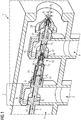
- Fig. 1 shows a perspective arrangement of a valve spindle arrangement 1.
- the valve spindle arrangement 1 comprises an inflow region 2.
- a steam which is generated, for example, in a steam generator, flows into the inflow region 2.
- This steam generally has very high temperatures and high pressures.
- the valve spindle arrangement 1 comprises a first outflow region 3 and a second outflow region 4. In the opened position of the valve spindle arrangement 1, the steam flows from the inflow region 2 into the first outflow region 3 and into the second outflow region 4.
- This valve spindle 5 is moved along a longitudinal direction 6.
- a first valve 7 the first valve spindle 5 is moved from left to right, as can be seen in figure 1 .
- the first valve cone 8 and the second valve cone 9 bear in contact with a first valve seat 10 and second valve seat 11, respectively. If the first valve spindle 5 is moved from left to right, an annular surface thereby opens between the first valve cone 8 and the first valve seat 10, and a further annular surface opens between the second valve cone 9 and the second valve seat 11.
- the terminal end 12 of the valve spindle 5 projects into a second valve spindle 13.
- the second valve spindle 13 has a cavity 14 in which the terminal end 12 of the first valve spindle 5 projects and can move within the cavity 14.
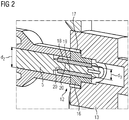
- the valve spindle 5 comprises a portion with a diameter d1. Following this portion is a portion with a smaller diameter d2. After the portion with the diameter d2 there follows a further portion with the diameter d3. The portion with the diameter d3 is explained in more detail in fig. 2 .
- the casing 15 has a spacing from the valve spindle 5 and is arranged in the region with the diameter d1 and partially also in the region with the diameter d2. In the region with the diameter d3, the casing 15 bears more or less in contact with the valve spindle 5.
- a spring (not shown) is arranged in the cavity 14 between the casing 15 and the second valve cone 9. The spring force of this spring results in the casing 15 being pressed against the second valve spindle 13. If the valve spindle 5 is moved from left to right, the first valve spindle 5 moves at first relative to the second valve spindle 13. The second valve spindle 13 is at first stationary.
- the terminal end 12 of the first valve spindle 5 is arranged within a bush 16 in such a way that the valve spindle 5 is movable relative to the first bush 16.
- the first bush 16 is in turn fixedly connected to the second valve spindle 13. This can occur by a thread between the first bush 16, a welded connection or a shrink fit between the first bush 16 and the second valve spindle 13.
- a release of the first bush 16 is prevented by a pin 17.
- This pin 17 is arranged between the first bush 16 and the second valve spindle 13. The pin 17 is secured against release by casing 15.
- Fig. 3 shows a perspective illustration of the terminal end 12 of the first valve spindle 5.
- the valve spindle 5 comprises a first feather key 18.
- a second feather key 19 is arranged opposite to the first feather key 18.
- the first feather key 18 and the second feather key 19 are formed from a harder material than the material of the first valve spindle 5.
- the first feather key 18 and the second feather key 19 are arranged in recesses 20 (not illustrated in fig. 3 but indicated in fig. 2 ).
- the mode of operation of the movement between the first valve spindle 5 and the first bush 16 becomes clear in figure 4.
- Fig. 4 shows a cross-sectional view of the valve spindle 5 and of the first bush 16.
- the first feather key 18 is arranged in a recess 20 which is arranged in the first valve spindle 5.
- the first feather key 18 is releasably inserted in this recess 20.
- a part of the first feather key 18 here projects from the surface of the first valve spindle 5.
- the part which projects here engages in a recess 21 in the first bush 16.
- a relative movement of the terminal end 12 of the first valve spindle 5 in a direction of rotation 22 is thereby prevented, wherein there is also preventing of rotation in other direction.
- the material of the first feather key 18 and of the second feather key 19 is harder than the material of the first valve spindle 5 and of the first bush 16.
- the material of the feather key 18 and of the feather key 19 is a stellite.
- the composition of stellite is here: Cr: 25 to 30% by weight Mo: max. 1% by weight W: 2 to 15% by weight C: 0.25 to 3.3% by weight Fe: max. 3% by weight Ni: max. 3% by weight Si: max. 2% by weight Mn: max. 1% by weight
- a sleeve (not shown), which likewise consists of a material which is harder than the material of the second bush 33 and the material of the first valve spindle 5, is arranged on the surface of the terminal end 12 of the first valve spindle 5 between the first feather key 18 and the second feather key 19.
- the sleeve is (in a manner not shown) arranged substantially in contact with the first bush 16.
- Fig. 5 shows a cross-sectional view of a terminal end of a valve spindle 23, according to the prior art.
- the valve spindle 23 has a total of six projections 34 which project into corresponding recesses 35 of a second valve spindle 24.
- a disadvantage with this design is that, with increasing duration, sticking or jamming between the valve spindle 23 and the valve spindle 24 is possible.
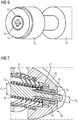
- Fig. 6 shows a perspective illustration of the first bush 16 and of the second valve spindle 13.
- the second valve spindle 13 has a third valve cone 25 which bears against a third valve seat 26 in the closed state.
- a fourth valve cone 27 Arranged behind it in the longitudinal direction 6 is a fourth valve cone 27 which, in the closed state, bears against a fourth valve seat 28.
- the valve spindle 23 is encased by a valve housing 29 in a longitudinal direction 6 behind the fourth valve cone 27.
- the second valve spindle 13 comprises a first region with a diameter d4 and, arranged in a longitudinal direction behind it, a region with a diameter d5 (see figure 8 ).
- the diameter d5 is substantially approximately identical to the diameter d3.
- a cavity is arranged between the valve spindle 23 in the region of the diameter d4 and the valve housing 29.
- the fourth valve cone 27 and the region with the diameter d4 are formed in such a way that a spring can be arranged therein which projects from the fourth valve cone 27 along the longitudinal direction up to the valve housing 29 (not shown).
- Fig. 7 shows an enlarged illustration of a terminal end 30 of the second valve spindle 13.
- fig. 7 shows a first spring 31 and a second spring 32.
- the first spring 31 and the second spring 32 exert a force on the valve housing 29 between the valve spindle 13 via the fourth valve cone 27.
- the valve spindle 13 has a first feather key 18 and a second feather key 19. These feather keys 18 and 19 are arranged in a second bush 33.
- the design of the first feather key 18 and of the second feather key 19 and also of the second bush 33 and of the pin 17 is identical to the embodiment according to figs. 2 , 3 and 4 . Reference should therefore be made at this point to the statements pertaining to the design of the terminal end 12 of the first valve spindle 5 and of the associated bush.
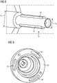
- Fig. 8 shows the perspective view of the end of the second valve spindle 13.
- Fig. 9 shows a perspective view of the valve housing 29.
- the valve housing 29 comprises three slots 34 which are designed to mount the valve housing 29 with a degree of leeway along a direction of rotation.
- the second bush 33 is arranged with the valve housing 29 either by screwing, welding or shrink-fitting.
- the mode of operation of the valve arrangement 1 occurs as follows: First of all, the first valve spindle 5 moves from left to right. The second valve spindle 13 remains stationary here. The movement of the first valve spindle 5 from left to right opens the annular surfaces between the first valve cone 8 and the first valve seat 10 and between the second valve cone 9 and the second valve seat 11. Here, the steam flows from the inflow region 2 into the outflow region 3.
- first valve spindle 5 has covered a certain distance, specifically a distance which is such that the transition from the region with the diameter d2 to the region with the diameter d3 bears against the second bush 33 or second valve spindle 13, a force is exerted on the second valve spindle 13 from the first valve spindle 5 directly (without the spring force between the casing 15 and the first valve spindle 5).
- a further movement of the valve spindle 5 then leads to a movement of the second valve spindle 13 from left to right.
- an annular surface between the third valve cone 25 and the third valve seat 26 and between the fourth valve cone 27 and the fourth valve seat 28 opens.
- the feather keys 18 and 19 move relatively with respect to the bushes 16 and 33.
Landscapes
- Engineering & Computer Science (AREA)
- General Engineering & Computer Science (AREA)
- Mechanical Engineering (AREA)
- Lift Valve (AREA)
Abstract
Description
- The invention relates to a valve spindle arrangement comprising a first valve spindle and a first bush, wherein the first valve spindle and the first bush are arranged so as to be displaceable relative to one another in a longitudinal direction, further comprising at least one feather key which is arranged on the first valve spindle, wherein the feather key projects in a recess of the bush in such a way that a rotation of the first valve spindle and of the bush with respect to one another is prevented.
- Such valve spindle arrangements are used, for example, for valves which are used in steam turbines. Such valves perform the task of changing the volumetric flow of a steam to a steam turbine. Known in this connection are so-called quick-closing and regulating valves. Quick-closing valves are designed to prevent the feed of steam from a steam generator to a steam turbine in a comparatively quick manner, this possibly occurring in a disturbance situation, for example. Additionally known are regulating valves which perform the task of changing the feed of steam, or the volumetric flow of the steam, from the steam generator to the steam turbine in such a way that an optimum amount of steam is available to the steam turbine.
- As a general rule, the valves are designed for application in steam turbine construction in such a way that a steam cone is arranged so as to be movable by a valve spindle and bears against a valve seat in the closed state. In operation, the valve cone is moved, inter alia, via the valve spindle away from the valve cone, with the result that a fluidic connection is formed between a valve inlet and a valve outlet, with the result that steam can flow from the valve inlet to the valve outlet.
- Moreover, still further embodiments of steam turbine valves are known, such as, for example, double seat steam turbine valves. Here, in principle, two valve cones are formed which each bear against a valve seat. The valve spindle exerts a movement in one direction, making possible a flow of steam on the respective valve cone. Such combinations of valve spindle and valve cones are usually guided at a terminal end within a bush. Since this relative movement of the valve spindle and the bush takes place at high temperatures and at critical steam parameters, it is possible that the relative movement between the valve spindle and the bush does not always occur in a friction-free manner. Jamming is sometimes possible, with the result that the valve cone cannot be moved further.
- It would therefore be desirable to have a possibility which demonstrates good movability of the valve spindle within a bush while also effectively preventing a rotation of the valve spindle.
- The invention comes in at this point. It is an object of the invention to specify a valve spindle arrangement which allows movability of the valve spindles even during critical states.
- This object is achieved by a valve spindle arrangement comprising a first valve spindle and a first bush, wherein the first valve spindle and the first bush are arranged so as to be displaceable relative to one another in a longitudinal direction, further comprising at least one feather key which is arranged on the first valve spindle, wherein the feather key projects in a recess of the bush in such a way that a rotation of the first valve spindle and of the bush with respect to one another is prevented, wherein the first valve spindle is formed from a first valve spindle material, and the first bush is formed from a first bush material, and the feather key is formed from a feather key material, wherein the feather key material is different from the first valve spindle material and/or the first bush material.
- The invention follows the approach that a feather key can be arranged in a recess of the first valve spindle, with the result that, after a certain use time, the feather key can be removed from the valve spindle and be exchanged in a service case, wherein the feather key is formed from a suitable material. Consequently, a frictionless movement of the valve spindle within the bush is possible after exchanging the feather keys or after reconditioning the feather keys.
- Advantageous developments are specified in the subclaims.
- In a first advantageous development, the feather key material has a greater hardness than the first bush material and/or the first valve spindle material.
- As a result, wedging or sticking of the feather key in the bush is effectively avoided.
- In a further advantageous embodiment, the feather key material has a hardness which is greater by 20% to 40%, in particular 25% to 35%, than the first bush material and the first valve spindle material.
- The material from the feather key is made from a material with a hard surface and is suitable for high temperatures above 500°C.
- The feather key is advantageously formed from stellite.
- Furthermore, the bush material is likewise advantageously formed from stellite.
- In a further advantageous development, the stellite has the following composition:
Cr: 25 to 30% by weight Mo: max. 1% by weight W: 2 to 15% by weight C: 0.25 to 3.3% by weight Fe: max. 3% by weight Ni: max. 3% by weight Si: max. 2% by weight Mn: max. 1% by weight - In a further advantageous development, the first valve spindle has a recess in which the feather key is arranged.
- A possibility is thereby provided of quickly removing the feather key from the first valve spindle for servicing purposes. The feather key can subsequently be cleaned if the surface of the feather key has changed. Such design allows to combine two materials in one part.
- In an advantageous development, the recess is formed in such a way that the feather key is not displaceable in the longitudinal direction relative to the first valve spindle.
- In an advantageous development, the first valve spindle has a second feather key, wherein the second feather key is arranged opposite to the feather key.
- As a result, a rotation of the valve spindle with respect to the bush is effectively prevented.
- In a further advantageous development, the bush is arranged in a second valve spindle.
- The bush is advantageously connected to the second valve spindle in such a way that a rotation of the bush relative to the second valve spindle is prevented.
- This can occur by welding, by shrink-fitting or by a thread between the bush and the second valve spindle.
- In a further advantageous development, at least one pin for securing is arranged between the bush and the second valve spindle.
- As a result, an unwanted release of the bush from the second valve spindle is effectively prevented.
- In a further advantageous development, the second valve spindle is provided on the end side with feather springs which engages in a second bush in such a way that a rotation is prevented.
- The function of the spring is to ensure closing force of the valve spindle. A further function of the spring is to prevent an unwanted release of the bush.
- Moreover, the second valve spindle comprises a valve cone which bears against a valve seat. Such a valve spindle arrangement is designed to open two steam flow lines to a steam turbine. Here, the first valve spindle comprises two valve cones which opens the first line to the steam turbine, and the second valve spindle comprises a further valve cone which opens the second line to the steam turbine.
- The second bush is advantageously fixedly connected to a valve housing.
- In an advantageous development, the feather key of the second valve spindle is formed from a second feather key material, and the second bush is formed from a second bush material, wherein the second feather key material has a greater hardness than the second bush material and/or the second valve spindle material.
- The second feather key material advantageously has a hardness which is greater by 20% to 40%, in particular 25% to 35%, than the second bush material and/or the valve spindle material.
- In an advantageous development, the feather key is formed from stellite.
- The second bush is advantageously formed from stellite.
- In a further advantageous development, the stellite of the second bush material has the following composition:
Cr: 25 to 30% by weight Mo: max. 1% by weight W: 2 to 15% by weight C: 0.25 to 3.3% by weight Fe: max. 3% by weight Ni: max. 3% by weight Si: max. 2% by weight Mn: max. 1% by weight - In an advantageous development, a sleeve is arranged on the first valve spindle between the first bush and the first valve spindle, wherein the sleeve is formed from a material which has a greater hardness than the material from which the first valve spindle is formed.
- This measure serves as it were to protect the surface of the first valve spindle. The sleeve prevents rubbing of the bush on the surface of the first valve spindle.
- In a further advantageous development, a second sleeve is arranged on the second valve spindle between the second bush and the second valve spindle, wherein the second sleeve is formed from a material which has a greater hardness than the material from which the second valve spindle is formed.
- Here, too, the surface of the second valve spindle is protected from destruction during the movement within the second bush by virtue of the fact that a sleeve is arranged on the surface, between the feather keys.
- In a further advantageous development, the feather key is arranged releasably on the first valve spindle and/or second valve spindle.
- The above-described properties, features and advantages of this invention and the manner in which they are achieved will become clearer and better understandable in conjunction with the following description of the exemplary embodiments which are explained in more detail in conjunction with the drawings.
- Here, identical components or components having an identical function are designated by identical reference signs.
- Exemplary embodiments of the invention are described below with reference to the drawings.
- This drawing is not intended to definitively represent the exemplary embodiments but rather is implemented, where it is useful for explanation, in a schematic and/or slightly distorted form. With regard to additions to the teachings which are directly evident from the drawing, reference is made to the relevant prior art.
- In the drawing:
- fig. 1
- shows a perspective illustration of a valve arrangement having two double seat valves;
- fig. 2
- shows an enlarged illustration of a detail from
fig. 1 ; - fig. 3
- shows an enlarged illustration of a detail from
fig. 2 ; - fig. 4
- shows a cross-sectional view of a valve spindle according to the invention;
- fig. 5
- shows a cross-sectional view of a valve spindle acc ording to the prior art;
- fig. 6
- shows a perspective illustration of a detail from
fig. 1 ; - fig. 7
- shows a perspective illustration of a second valve spindle;
- fig. 8
- shows an enlarged illustration of a detail from
fig. 7 ; and - fig. 9
- shows a perspective view of a valve housing with bush.
-
Fig. 1 shows a perspective arrangement of a valve spindle arrangement 1. The valve spindle arrangement 1 comprises an inflow region 2. A steam, which is generated, for example, in a steam generator, flows into the inflow region 2. This steam generally has very high temperatures and high pressures. Furthermore, the valve spindle arrangement 1 comprises a first outflow region 3 and asecond outflow region 4. In the opened position of the valve spindle arrangement 1, the steam flows from the inflow region 2 into the first outflow region 3 and into thesecond outflow region 4. - The steam flows from the inflow region 2 first to the first outflow region 3. This occurs via the movement of a
first valve spindle 5. Thisvalve spindle 5 is moved along alongitudinal direction 6. To open a first valve 7, thefirst valve spindle 5 is moved from left to right, as can be seen infigure 1 . Arranged on thefirst valve spindle 5 is afirst valve cone 8 and, behind it, a second valve cone 9. In the closed state, thefirst valve cone 8 and the second valve cone 9 bear in contact with afirst valve seat 10 and second valve seat 11, respectively. If thefirst valve spindle 5 is moved from left to right, an annular surface thereby opens between thefirst valve cone 8 and thefirst valve seat 10, and a further annular surface opens between the second valve cone 9 and the second valve seat 11. As a result, a steam flows between thevalve seat 10 and thefirst valve cone 8 from the inflow region 2 into the first outflow region 3. A steam likewise flows from the inflow region 2 through the gap between the second valve cone 9 and the second valve seat 11 into the first outflow region 3. - Here, the
terminal end 12 of thevalve spindle 5 projects into asecond valve spindle 13. Here, thesecond valve spindle 13 has acavity 14 in which theterminal end 12 of thefirst valve spindle 5 projects and can move within thecavity 14. - The
valve spindle 5 comprises a portion with a diameter d1. Following this portion is a portion with a smaller diameter d2. After the portion with the diameter d2 there follows a further portion with the diameter d3. The portion with the diameter d3 is explained in more detail infig. 2 . - Around the
valve spindle 5 is arranged amovable casing 15. Thecasing 15 has a spacing from thevalve spindle 5 and is arranged in the region with the diameter d1 and partially also in the region with the diameter d2. In the region with the diameter d3, thecasing 15 bears more or less in contact with thevalve spindle 5. A spring (not shown) is arranged in thecavity 14 between thecasing 15 and the second valve cone 9. The spring force of this spring results in thecasing 15 being pressed against thesecond valve spindle 13. If thevalve spindle 5 is moved from left to right, thefirst valve spindle 5 moves at first relative to thesecond valve spindle 13. Thesecond valve spindle 13 is at first stationary. Theterminal end 12 of thefirst valve spindle 5 is arranged within abush 16 in such a way that thevalve spindle 5 is movable relative to thefirst bush 16. Thefirst bush 16 is in turn fixedly connected to thesecond valve spindle 13. This can occur by a thread between thefirst bush 16, a welded connection or a shrink fit between thefirst bush 16 and thesecond valve spindle 13. A release of thefirst bush 16 is prevented by apin 17. Thispin 17 is arranged between thefirst bush 16 and thesecond valve spindle 13. Thepin 17 is secured against release by casing 15. -
Fig. 3 shows a perspective illustration of theterminal end 12 of thefirst valve spindle 5. As can be seen infig. 3 , thevalve spindle 5 comprises afirst feather key 18. In a further embodiment, asecond feather key 19 is arranged opposite to thefirst feather key 18. Thefirst feather key 18 and thesecond feather key 19 are formed from a harder material than the material of thefirst valve spindle 5. Here, thefirst feather key 18 and thesecond feather key 19 are arranged in recesses 20 (not illustrated infig. 3 but indicated infig. 2 ). The mode of operation of the movement between thefirst valve spindle 5 and thefirst bush 16 becomes clear infigure 4. Fig. 4 shows a cross-sectional view of thevalve spindle 5 and of thefirst bush 16. As can be seen infig. 4 , thefirst feather key 18 is arranged in arecess 20 which is arranged in thefirst valve spindle 5. Thefirst feather key 18 is releasably inserted in thisrecess 20. As can be seen infig. 4 , a part of thefirst feather key 18 here projects from the surface of thefirst valve spindle 5. The part which projects here engages in arecess 21 in thefirst bush 16. A relative movement of theterminal end 12 of thefirst valve spindle 5 in a direction ofrotation 22 is thereby prevented, wherein there is also preventing of rotation in other direction. Here, the material of thefirst feather key 18 and of thesecond feather key 19 is harder than the material of thefirst valve spindle 5 and of thefirst bush 16. Here, the material of thefeather key 18 and of thefeather key 19 is a stellite. The composition of stellite is here:Cr: 25 to 30% by weight Mo: max. 1% by weight W: 2 to 15% by weight C: 0.25 to 3.3% by weight Fe: max. 3% by weight Ni: max. 3% by weight Si: max. 2% by weight Mn: max. 1% by weight - A sleeve (not shown), which likewise consists of a material which is harder than the material of the
second bush 33 and the material of thefirst valve spindle 5, is arranged on the surface of theterminal end 12 of thefirst valve spindle 5 between thefirst feather key 18 and thesecond feather key 19. The sleeve is (in a manner not shown) arranged substantially in contact with thefirst bush 16. -
Fig. 5 shows a cross-sectional view of a terminal end of avalve spindle 23, according to the prior art. Here, thevalve spindle 23 has a total of sixprojections 34 which project into correspondingrecesses 35 of asecond valve spindle 24. A disadvantage with this design is that, with increasing duration, sticking or jamming between thevalve spindle 23 and thevalve spindle 24 is possible. -
Fig. 6 shows a perspective illustration of thefirst bush 16 and of thesecond valve spindle 13. Thesecond valve spindle 13 has athird valve cone 25 which bears against athird valve seat 26 in the closed state. Arranged behind it in thelongitudinal direction 6 is afourth valve cone 27 which, in the closed state, bears against afourth valve seat 28. - The
valve spindle 23 is encased by avalve housing 29 in alongitudinal direction 6 behind thefourth valve cone 27. Here, thesecond valve spindle 13 comprises a first region with a diameter d4 and, arranged in a longitudinal direction behind it, a region with a diameter d5 (seefigure 8 ). The diameter d5 is substantially approximately identical to the diameter d3. A cavity is arranged between thevalve spindle 23 in the region of the diameter d4 and thevalve housing 29. Thefourth valve cone 27 and the region with the diameter d4 are formed in such a way that a spring can be arranged therein which projects from thefourth valve cone 27 along the longitudinal direction up to the valve housing 29 (not shown). -
Fig. 7 shows an enlarged illustration of aterminal end 30 of thesecond valve spindle 13. Here,fig. 7 shows afirst spring 31 and asecond spring 32. Thefirst spring 31 and thesecond spring 32 exert a force on thevalve housing 29 between thevalve spindle 13 via thefourth valve cone 27. Here, just like the end of thefirst valve spindle 5, thevalve spindle 13 has afirst feather key 18 and asecond feather key 19. Thesefeather keys second bush 33. The design of thefirst feather key 18 and of thesecond feather key 19 and also of thesecond bush 33 and of thepin 17 is identical to the embodiment according tofigs. 2 ,3 and 4 . Reference should therefore be made at this point to the statements pertaining to the design of theterminal end 12 of thefirst valve spindle 5 and of the associated bush. -
Fig. 8 shows the perspective view of the end of thesecond valve spindle 13. -
Fig. 9 shows a perspective view of thevalve housing 29. Thevalve housing 29 comprises threeslots 34 which are designed to mount thevalve housing 29 with a degree of leeway along a direction of rotation. Here, thesecond bush 33 is arranged with thevalve housing 29 either by screwing, welding or shrink-fitting. - The mode of operation of the valve arrangement 1 occurs as follows:
First of all, thefirst valve spindle 5 moves from left to right. Thesecond valve spindle 13 remains stationary here. The movement of thefirst valve spindle 5 from left to right opens the annular surfaces between thefirst valve cone 8 and thefirst valve seat 10 and between the second valve cone 9 and the second valve seat 11. Here, the steam flows from the inflow region 2 into the outflow region 3. If thefirst valve spindle 5 has covered a certain distance, specifically a distance which is such that the transition from the region with the diameter d2 to the region with the diameter d3 bears against thesecond bush 33 orsecond valve spindle 13, a force is exerted on thesecond valve spindle 13 from thefirst valve spindle 5 directly (without the spring force between thecasing 15 and the first valve spindle 5). A further movement of thevalve spindle 5 then leads to a movement of thesecond valve spindle 13 from left to right. Here, an annular surface between thethird valve cone 25 and thethird valve seat 26 and between thefourth valve cone 27 and thefourth valve seat 28 opens. As a result, the steam flows from the inflow region 2 into thesecond outflow region 4. Here, thefeather keys bushes - Although the invention has been illustrated and described in more detail by the preferred exemplary embodiment, the invention is not restricted by the disclosed examples and other variations can be derived therefrom by a person skilled in the art without departing from the scope of protection of the invention.
Claims (25)
- A valve spindle arrangement (1)
comprising
a first valve spindle (5) and a first bush (16),
wherein the first valve spindle (5) and the first bush (16) are arranged so as to be displaceable relative to one another in a longitudinal direction (6),
further comprising at least one feather key (18) which is arranged on the first valve spindle (5),
wherein the feather key (18) projects into a recess (20) of the first bush (16) in such a way that a rotation of the first valve spindle (5) and of the bush (16) with respect to one another is prevented,
characterized in that
the first valve spindle (5) is formed from a first valve spindle material, and the first bush (16) is formed from a first bush material, and the feather key (18) is formed from a feather key material,
wherein the feather key material is different from the first valve spindle material and/or the first bush material. - The valve spindle arrangement (1) as claimed in claim 1, wherein the feather key material has a greater hardness than the first bush material and/or the first valve spindle material.
- The valve spindle arrangement (1) as claimed in claim 2, wherein the feather key material has a hardness which is greater by 20% to 40%, in particular by 25% to 35%, than the first bush material and the first valve spindle material.
- The valve spindle arrangement (1) as claimed in claim 2 or 3,
wherein the feather key (18) is formed from stellite. - The valve spindle arrangement (1) as claimed in claim 2, 3 or 4,
wherein the first bush material is formed from stellite. - The valve spindle arrangement (1) as claimed in claim 4 or 5,
wherein stellite has the following composition:Cr: 25 to 30% by weight Mo: max. 1% by weight W: 2 to 15% by weight C: 0.25 to 3.3% by weight Fe: max. 3% by weight Ni: max. 3% by weight Si: max. 2% by weight Mn: max. 1% by weight. - The valve spindle arrangement (1) as claimed in one of the preceding claims,
wherein the first valve spindle (5) has a recess (20) in which the feather key (18) is arranged. - The valve spindle arrangement (1) as claimed in one of the preceding claims,
wherein the recess (20) is formed in such a way that the feather key (18) is not displaceable in the longitudinal direction (6) relative to the first valve spindle (5). - The valve spindle arrangement (1) as claimed in one of the preceding claims,
wherein the first valve spindle (5) comprises a second feather key (19), wherein the second feather key (19) is arranged opposite to the first feather key (18). - The valve spindle arrangement (1) as claimed in one of the preceding claims,
wherein the bush (16) is arranged in a second valve spindle (13). - The valve spindle arrangement (1) as claimed in claim 10,
wherein the bush (16) is connected to the second valve spindle (13) in such a way that a rotation of the bush (16) relative to the second valve spindle (13) is prevented. - The valve spindle arrangement (1) as claimed in claim 11,
wherein the second valve spindle (13) has an end-side cavity (14), and the bush (16) is connected in this cavity (14) to the second valve spindle (13) by a shrink fit. - The valve spindle arrangement (1) as claimed in either of claims 5 and 6,
wherein at least one pin (17) for securing is arranged between the bush (16) and the second valve spindle (13). - The valve spindle arrangement (1) as claimed in one of claims 10 to 13,
wherein the second valve spindle (13) is provided on the end side with feather keys (18, 19) which engages in a second bush (33) in such a way that a rotation is prevented. - The valve spindle arrangement (1) as claimed in claim 14,
wherein the second bush (33) is fixedly connected to a valve housing (29). - The valve spindle arrangement (1) as claimed in one of claims 10 to 15,
wherein the feather key (18, 19) of the second valve spindle (13) is formed from a feather key material, and the second bush (33) is formed from a second bush material, wherein the feather key material has a greater hardness than the second bush material and/or the second valve spindle material. - The valve spindle arrangement (1) as claimed in claim 16,
wherein the feather key material material has a hardness which is greater by 20% to 40%, in particular by 25% to 35%, than the second bush material. - The valve spindle arrangement (1) as claimed in claim 15 or 16,
wherein the second valve spindle (13) is formed from stellite. - The valve spindle arrangement (1) as claimed in claim 16, 17 or 18,
wherein the second bush (33) is formed from stellite. - The valve spindle arrangement (1) as claimed in claim 18 or 19,
wherein stellite has the following composition:Cr: 25 to 30% by weight Mo: max. 1% by weight W: 2 to 15% by weight C: 0.25 to 3.3% by weight Fe: max. 3% by weight Ni: max. 3% by weight Si: max. 2% by weight Mn: max. 1% by weight. - The valve spindle arrangement (1) as claimed in one of the preceding claims,
wherein a sleeve is arranged on the first valve spindle (5) between the first bush (16) and the first valve spindle (5), wherein the sleeve is formed from a material which has a greater hardness than the material from which the first valve spindle (5) is formed. - The valve spindle arrangement (21) as claimed in one of the preceding claims,
wherein a second sleeve is arranged on the second valve spindle (13) between the second bush (33) and the second valve spindle (13), wherein the second sleeve is formed from a material which has a greater hardness than the material from which the second valve spindle (13) is formed. - The valve spindle arrangement (1) as claimed in one of the preceding claims,
wherein the feather key (18, 19) is arranged releasably on the first valve spindle (5) and/or second valve spindle (13). - A valve having a valve spindle arrangement as claimed in one of claims 1 to 20.
- The valve as claimed in claim 21,
wherein the first valve spindle (5) is designed to move a first valve cone (8), and the second valve spindle (13) is designed to move a third valve cone (25).
Priority Applications (2)
| Application Number | Priority Date | Filing Date | Title |
|---|---|---|---|
| EP19175637.8A EP3742028B1 (en) | 2019-05-21 | 2019-05-21 | Protection against rotation for valve spindles |
| PL19175637T PL3742028T3 (en) | 2019-05-21 | 2019-05-21 | Protection against rotation for valve spindles |
Applications Claiming Priority (1)
| Application Number | Priority Date | Filing Date | Title |
|---|---|---|---|
| EP19175637.8A EP3742028B1 (en) | 2019-05-21 | 2019-05-21 | Protection against rotation for valve spindles |
Publications (2)
| Publication Number | Publication Date |
|---|---|
| EP3742028A1 true EP3742028A1 (en) | 2020-11-25 |
| EP3742028B1 EP3742028B1 (en) | 2021-06-30 |
Family
ID=66625857
Family Applications (1)
| Application Number | Title | Priority Date | Filing Date |
|---|---|---|---|
| EP19175637.8A Active EP3742028B1 (en) | 2019-05-21 | 2019-05-21 | Protection against rotation for valve spindles |
Country Status (2)
| Country | Link |
|---|---|
| EP (1) | EP3742028B1 (en) |
| PL (1) | PL3742028T3 (en) |
Citations (1)
| Publication number | Priority date | Publication date | Assignee | Title |
|---|---|---|---|---|
| EP3431840A1 (en) * | 2017-07-20 | 2019-01-23 | Siemens Aktiengesellschaft | Valve arrangement for fluid power equipment |
-
2019
- 2019-05-21 EP EP19175637.8A patent/EP3742028B1/en active Active
- 2019-05-21 PL PL19175637T patent/PL3742028T3/en unknown
Patent Citations (1)
| Publication number | Priority date | Publication date | Assignee | Title |
|---|---|---|---|---|
| EP3431840A1 (en) * | 2017-07-20 | 2019-01-23 | Siemens Aktiengesellschaft | Valve arrangement for fluid power equipment |
Also Published As
| Publication number | Publication date |
|---|---|
| PL3742028T3 (en) | 2021-12-13 |
| EP3742028B1 (en) | 2021-06-30 |
Similar Documents
| Publication | Publication Date | Title |
|---|---|---|
| CA2141005C (en) | Wire cutting insert for gate valve | |
| CA2982470C (en) | Valves including multiple seats and related assemblies and methods | |
| US8322373B2 (en) | Axial drag valve with internal sleeve actuator | |
| RU2559955C2 (en) | Valve fitted by ceramic gate with protected blocking surfaces | |
| JP2011226650A (en) | Fluid flow control device | |
| CN105909381B (en) | With the variable compression ratio that can be set and with the internal combustion engine of switching module | |
| CN101135378A (en) | Variable clearance positive pressure seal ring and bearing device with helical spring | |
| EP0449668A1 (en) | Shock absorbing sealing means for flow control devices | |
| EP3742028B1 (en) | Protection against rotation for valve spindles | |
| US7383859B2 (en) | Main steam valve for a steam turbine | |
| JP2014070513A (en) | Steam valve for steam turbine | |
| JPS597877B2 (en) | pressure fluid control valve | |
| CN109555863A (en) | It adjusts for the overtravel in double furcation plugs used in valve module | |
| JP2012097592A (en) | Steam valve device | |
| US6805162B2 (en) | Erosion reducing valve plug and seat ring | |
| JP4648857B2 (en) | Steam control valve | |
| US2988105A (en) | Throttling valve | |
| JP3721256B2 (en) | Poppet valve | |
| JP7325118B2 (en) | Pressure reducing valve with automatic cleaning function | |
| EP3853506B1 (en) | Combination valve consisting of quick-acting valve and control valve for a steam circuit and sil 3 certified safety circuit | |
| JP7378998B2 (en) | erosion resistant steam valve | |
| CN103429858A (en) | Cylinder structure of internal combustion engine | |
| JP6843387B2 (en) | Check valve | |
| CN208057971U (en) | More cut-off core assemblies for control valve | |
| JP4025172B2 (en) | Gas turbine equipment |
Legal Events
| Date | Code | Title | Description |
|---|---|---|---|
| PUAI | Public reference made under article 153(3) epc to a published international application that has entered the european phase |
Free format text: ORIGINAL CODE: 0009012 |
|
| STAA | Information on the status of an ep patent application or granted ep patent |
Free format text: STATUS: THE APPLICATION HAS BEEN PUBLISHED |
|
| STAA | Information on the status of an ep patent application or granted ep patent |
Free format text: STATUS: REQUEST FOR EXAMINATION WAS MADE |
|
| AK | Designated contracting states |
Kind code of ref document: A1 Designated state(s): AL AT BE BG CH CY CZ DE DK EE ES FI FR GB GR HR HU IE IS IT LI LT LU LV MC MK MT NL NO PL PT RO RS SE SI SK SM TR |
|
| AX | Request for extension of the european patent |
Extension state: BA ME |
|
| 17P | Request for examination filed |
Effective date: 20201103 |
|
| RBV | Designated contracting states (corrected) |
Designated state(s): AL AT BE BG CH CY CZ DE DK EE ES FI FR GB GR HR HU IE IS IT LI LT LU LV MC MK MT NL NO PL PT RO RS SE SI SK SM TR |
|
| RIC1 | Information provided on ipc code assigned before grant |
Ipc: F16K 11/16 20060101ALI20201201BHEP Ipc: F16K 1/44 20060101AFI20201201BHEP Ipc: F01D 17/14 20060101ALI20201201BHEP Ipc: F16K 11/07 20060101ALI20201201BHEP |
|
| GRAP | Despatch of communication of intention to grant a patent |
Free format text: ORIGINAL CODE: EPIDOSNIGR1 |
|
| STAA | Information on the status of an ep patent application or granted ep patent |
Free format text: STATUS: GRANT OF PATENT IS INTENDED |
|
| INTG | Intention to grant announced |
Effective date: 20210118 |
|
| RAP1 | Party data changed (applicant data changed or rights of an application transferred) |
Owner name: SIEMENS ENERGY GLOBAL GMBH & CO. KG |
|
| GRAS | Grant fee paid |
Free format text: ORIGINAL CODE: EPIDOSNIGR3 |
|
| GRAA | (expected) grant |
Free format text: ORIGINAL CODE: 0009210 |
|
| STAA | Information on the status of an ep patent application or granted ep patent |
Free format text: STATUS: THE PATENT HAS BEEN GRANTED |
|
| AK | Designated contracting states |
Kind code of ref document: B1 Designated state(s): AL AT BE BG CH CY CZ DE DK EE ES FI FR GB GR HR HU IE IS IT LI LT LU LV MC MK MT NL NO PL PT RO RS SE SI SK SM TR |
|
| REG | Reference to a national code |
Ref country code: CH Ref legal event code: EP |
|
| REG | Reference to a national code |
Ref country code: DE Ref legal event code: R096 Ref document number: 602019005686 Country of ref document: DE Ref country code: AT Ref legal event code: REF Ref document number: 1406636 Country of ref document: AT Kind code of ref document: T Effective date: 20210715 |
|
| REG | Reference to a national code |
Ref country code: IE Ref legal event code: FG4D |
|
| REG | Reference to a national code |
Ref country code: LT Ref legal event code: MG9D |
|
| PG25 | Lapsed in a contracting state [announced via postgrant information from national office to epo] |
Ref country code: HR Free format text: LAPSE BECAUSE OF FAILURE TO SUBMIT A TRANSLATION OF THE DESCRIPTION OR TO PAY THE FEE WITHIN THE PRESCRIBED TIME-LIMIT Effective date: 20210630 Ref country code: FI Free format text: LAPSE BECAUSE OF FAILURE TO SUBMIT A TRANSLATION OF THE DESCRIPTION OR TO PAY THE FEE WITHIN THE PRESCRIBED TIME-LIMIT Effective date: 20210630 Ref country code: BG Free format text: LAPSE BECAUSE OF FAILURE TO SUBMIT A TRANSLATION OF THE DESCRIPTION OR TO PAY THE FEE WITHIN THE PRESCRIBED TIME-LIMIT Effective date: 20210930 |
|
| REG | Reference to a national code |
Ref country code: NL Ref legal event code: MP Effective date: 20210630 |
|
| REG | Reference to a national code |
Ref country code: AT Ref legal event code: MK05 Ref document number: 1406636 Country of ref document: AT Kind code of ref document: T Effective date: 20210630 |
|
| PG25 | Lapsed in a contracting state [announced via postgrant information from national office to epo] |
Ref country code: GR Free format text: LAPSE BECAUSE OF FAILURE TO SUBMIT A TRANSLATION OF THE DESCRIPTION OR TO PAY THE FEE WITHIN THE PRESCRIBED TIME-LIMIT Effective date: 20211001 Ref country code: RS Free format text: LAPSE BECAUSE OF FAILURE TO SUBMIT A TRANSLATION OF THE DESCRIPTION OR TO PAY THE FEE WITHIN THE PRESCRIBED TIME-LIMIT Effective date: 20210630 Ref country code: SE Free format text: LAPSE BECAUSE OF FAILURE TO SUBMIT A TRANSLATION OF THE DESCRIPTION OR TO PAY THE FEE WITHIN THE PRESCRIBED TIME-LIMIT Effective date: 20210630 Ref country code: LV Free format text: LAPSE BECAUSE OF FAILURE TO SUBMIT A TRANSLATION OF THE DESCRIPTION OR TO PAY THE FEE WITHIN THE PRESCRIBED TIME-LIMIT Effective date: 20210630 Ref country code: NO Free format text: LAPSE BECAUSE OF FAILURE TO SUBMIT A TRANSLATION OF THE DESCRIPTION OR TO PAY THE FEE WITHIN THE PRESCRIBED TIME-LIMIT Effective date: 20210930 |
|
| PG25 | Lapsed in a contracting state [announced via postgrant information from national office to epo] |
Ref country code: ES Free format text: LAPSE BECAUSE OF FAILURE TO SUBMIT A TRANSLATION OF THE DESCRIPTION OR TO PAY THE FEE WITHIN THE PRESCRIBED TIME-LIMIT Effective date: 20210630 Ref country code: EE Free format text: LAPSE BECAUSE OF FAILURE TO SUBMIT A TRANSLATION OF THE DESCRIPTION OR TO PAY THE FEE WITHIN THE PRESCRIBED TIME-LIMIT Effective date: 20210630 Ref country code: SK Free format text: LAPSE BECAUSE OF FAILURE TO SUBMIT A TRANSLATION OF THE DESCRIPTION OR TO PAY THE FEE WITHIN THE PRESCRIBED TIME-LIMIT Effective date: 20210630 Ref country code: AT Free format text: LAPSE BECAUSE OF FAILURE TO SUBMIT A TRANSLATION OF THE DESCRIPTION OR TO PAY THE FEE WITHIN THE PRESCRIBED TIME-LIMIT Effective date: 20210630 Ref country code: NL Free format text: LAPSE BECAUSE OF FAILURE TO SUBMIT A TRANSLATION OF THE DESCRIPTION OR TO PAY THE FEE WITHIN THE PRESCRIBED TIME-LIMIT Effective date: 20210630 Ref country code: RO Free format text: LAPSE BECAUSE OF FAILURE TO SUBMIT A TRANSLATION OF THE DESCRIPTION OR TO PAY THE FEE WITHIN THE PRESCRIBED TIME-LIMIT Effective date: 20210630 Ref country code: PT Free format text: LAPSE BECAUSE OF FAILURE TO SUBMIT A TRANSLATION OF THE DESCRIPTION OR TO PAY THE FEE WITHIN THE PRESCRIBED TIME-LIMIT Effective date: 20211102 Ref country code: SM Free format text: LAPSE BECAUSE OF FAILURE TO SUBMIT A TRANSLATION OF THE DESCRIPTION OR TO PAY THE FEE WITHIN THE PRESCRIBED TIME-LIMIT Effective date: 20210630 |
|
| REG | Reference to a national code |
Ref country code: DE Ref legal event code: R097 Ref document number: 602019005686 Country of ref document: DE |
|
| PG25 | Lapsed in a contracting state [announced via postgrant information from national office to epo] |
Ref country code: DK Free format text: LAPSE BECAUSE OF FAILURE TO SUBMIT A TRANSLATION OF THE DESCRIPTION OR TO PAY THE FEE WITHIN THE PRESCRIBED TIME-LIMIT Effective date: 20210630 |
|
| PLBE | No opposition filed within time limit |
Free format text: ORIGINAL CODE: 0009261 |
|
| STAA | Information on the status of an ep patent application or granted ep patent |
Free format text: STATUS: NO OPPOSITION FILED WITHIN TIME LIMIT |
|
| PG25 | Lapsed in a contracting state [announced via postgrant information from national office to epo] |
Ref country code: AL Free format text: LAPSE BECAUSE OF FAILURE TO SUBMIT A TRANSLATION OF THE DESCRIPTION OR TO PAY THE FEE WITHIN THE PRESCRIBED TIME-LIMIT Effective date: 20210630 |
|
| 26N | No opposition filed |
Effective date: 20220331 |
|
| REG | Reference to a national code |
Ref country code: CH Ref legal event code: PL |
|
| REG | Reference to a national code |
Ref country code: BE Ref legal event code: MM Effective date: 20220531 |
|
| PG25 | Lapsed in a contracting state [announced via postgrant information from national office to epo] |
Ref country code: MC Free format text: LAPSE BECAUSE OF FAILURE TO SUBMIT A TRANSLATION OF THE DESCRIPTION OR TO PAY THE FEE WITHIN THE PRESCRIBED TIME-LIMIT Effective date: 20210630 Ref country code: LU Free format text: LAPSE BECAUSE OF NON-PAYMENT OF DUE FEES Effective date: 20220521 Ref country code: LI Free format text: LAPSE BECAUSE OF NON-PAYMENT OF DUE FEES Effective date: 20220531 Ref country code: CH Free format text: LAPSE BECAUSE OF NON-PAYMENT OF DUE FEES Effective date: 20220531 |
|
| PG25 | Lapsed in a contracting state [announced via postgrant information from national office to epo] |
Ref country code: LT Free format text: LAPSE BECAUSE OF FAILURE TO SUBMIT A TRANSLATION OF THE DESCRIPTION OR TO PAY THE FEE WITHIN THE PRESCRIBED TIME-LIMIT Effective date: 20210630 Ref country code: IE Free format text: LAPSE BECAUSE OF NON-PAYMENT OF DUE FEES Effective date: 20220521 Ref country code: FR Free format text: LAPSE BECAUSE OF NON-PAYMENT OF DUE FEES Effective date: 20220531 |
|
| PG25 | Lapsed in a contracting state [announced via postgrant information from national office to epo] |
Ref country code: BE Free format text: LAPSE BECAUSE OF NON-PAYMENT OF DUE FEES Effective date: 20220531 |
|
| GBPC | Gb: european patent ceased through non-payment of renewal fee |
Effective date: 20230521 |
|
| PG25 | Lapsed in a contracting state [announced via postgrant information from national office to epo] |
Ref country code: MK Free format text: LAPSE BECAUSE OF FAILURE TO SUBMIT A TRANSLATION OF THE DESCRIPTION OR TO PAY THE FEE WITHIN THE PRESCRIBED TIME-LIMIT Effective date: 20210630 Ref country code: CY Free format text: LAPSE BECAUSE OF FAILURE TO SUBMIT A TRANSLATION OF THE DESCRIPTION OR TO PAY THE FEE WITHIN THE PRESCRIBED TIME-LIMIT Effective date: 20210630 Ref country code: GB Free format text: LAPSE BECAUSE OF NON-PAYMENT OF DUE FEES Effective date: 20230521 |
|
| PG25 | Lapsed in a contracting state [announced via postgrant information from national office to epo] |
Ref country code: HU Free format text: LAPSE BECAUSE OF FAILURE TO SUBMIT A TRANSLATION OF THE DESCRIPTION OR TO PAY THE FEE WITHIN THE PRESCRIBED TIME-LIMIT; INVALID AB INITIO Effective date: 20190521 |
|
| PG25 | Lapsed in a contracting state [announced via postgrant information from national office to epo] |
Ref country code: MT Free format text: LAPSE BECAUSE OF FAILURE TO SUBMIT A TRANSLATION OF THE DESCRIPTION OR TO PAY THE FEE WITHIN THE PRESCRIBED TIME-LIMIT Effective date: 20210630 |
|
| PGFP | Annual fee paid to national office [announced via postgrant information from national office to epo] |
Ref country code: PL Payment date: 20250429 Year of fee payment: 7 Ref country code: DE Payment date: 20250528 Year of fee payment: 7 |
|
| PGFP | Annual fee paid to national office [announced via postgrant information from national office to epo] |
Ref country code: IT Payment date: 20250522 Year of fee payment: 7 |
|
| PGFP | Annual fee paid to national office [announced via postgrant information from national office to epo] |
Ref country code: CZ Payment date: 20250506 Year of fee payment: 7 |
|
| PG25 | Lapsed in a contracting state [announced via postgrant information from national office to epo] |
Ref country code: TR Free format text: LAPSE BECAUSE OF FAILURE TO SUBMIT A TRANSLATION OF THE DESCRIPTION OR TO PAY THE FEE WITHIN THE PRESCRIBED TIME-LIMIT Effective date: 20210630 |