EP3742000A1 - Construction machine - Google Patents
Construction machine Download PDFInfo
- Publication number
- EP3742000A1 EP3742000A1 EP18901447.5A EP18901447A EP3742000A1 EP 3742000 A1 EP3742000 A1 EP 3742000A1 EP 18901447 A EP18901447 A EP 18901447A EP 3742000 A1 EP3742000 A1 EP 3742000A1
- Authority
- EP
- European Patent Office
- Prior art keywords
- rod
- valve
- flow rate
- pressure
- pump
- Prior art date
- Legal status (The legal status is an assumption and is not a legal conclusion. Google has not performed a legal analysis and makes no representation as to the accuracy of the status listed.)
- Granted
Links
Images



Classifications
-
- E—FIXED CONSTRUCTIONS
- E02—HYDRAULIC ENGINEERING; FOUNDATIONS; SOIL SHIFTING
- E02F—DREDGING; SOIL-SHIFTING
- E02F9/00—Component parts of dredgers or soil-shifting machines, not restricted to one of the kinds covered by groups E02F3/00 - E02F7/00
- E02F9/20—Drives; Control devices
- E02F9/22—Hydraulic or pneumatic drives
- E02F9/2221—Control of flow rate; Load sensing arrangements
- E02F9/2239—Control of flow rate; Load sensing arrangements using two or more pumps with cross-assistance
- E02F9/2242—Control of flow rate; Load sensing arrangements using two or more pumps with cross-assistance including an electronic controller
-
- F—MECHANICAL ENGINEERING; LIGHTING; HEATING; WEAPONS; BLASTING
- F15—FLUID-PRESSURE ACTUATORS; HYDRAULICS OR PNEUMATICS IN GENERAL
- F15B—SYSTEMS ACTING BY MEANS OF FLUIDS IN GENERAL; FLUID-PRESSURE ACTUATORS, e.g. SERVOMOTORS; DETAILS OF FLUID-PRESSURE SYSTEMS, NOT OTHERWISE PROVIDED FOR
- F15B11/00—Servomotor systems without provision for follow-up action ; Circuits therefor
- F15B11/02—Systems essentially incorporating special features for controlling the speed or the actuating force of an output member
- F15B11/04—Systems essentially incorporating special features for controlling the speed or the actuating force of an output member for controlling the speed
- F15B11/042—Systems essentially incorporating special features for controlling the speed or the actuating force of an output member for controlling the speed by means in the feed line
- F15B11/0426—Systems essentially incorporating special features for controlling the speed or the actuating force of an output member for controlling the speed by means in the feed line by controlling the number of pumps or parallel valves switched on
-
- E—FIXED CONSTRUCTIONS
- E02—HYDRAULIC ENGINEERING; FOUNDATIONS; SOIL SHIFTING
- E02F—DREDGING; SOIL-SHIFTING
- E02F3/00—Dredgers; Soil-shifting machines
- E02F3/04—Dredgers; Soil-shifting machines mechanically-driven
- E02F3/28—Dredgers; Soil-shifting machines mechanically-driven with digging tools mounted on a dipper- or bucket-arm, i.e. there is either one arm or a pair of arms, e.g. dippers, buckets
- E02F3/36—Component parts
- E02F3/42—Drives for dippers, buckets, dipper-arms or bucket-arms
- E02F3/425—Drive systems for dipper-arms, backhoes or the like
-
- E—FIXED CONSTRUCTIONS
- E02—HYDRAULIC ENGINEERING; FOUNDATIONS; SOIL SHIFTING
- E02F—DREDGING; SOIL-SHIFTING
- E02F3/00—Dredgers; Soil-shifting machines
- E02F3/04—Dredgers; Soil-shifting machines mechanically-driven
- E02F3/28—Dredgers; Soil-shifting machines mechanically-driven with digging tools mounted on a dipper- or bucket-arm, i.e. there is either one arm or a pair of arms, e.g. dippers, buckets
- E02F3/36—Component parts
- E02F3/42—Drives for dippers, buckets, dipper-arms or bucket-arms
- E02F3/43—Control of dipper or bucket position; Control of sequence of drive operations
- E02F3/435—Control of dipper or bucket position; Control of sequence of drive operations for dipper-arms, backhoes or the like
-
- E—FIXED CONSTRUCTIONS
- E02—HYDRAULIC ENGINEERING; FOUNDATIONS; SOIL SHIFTING
- E02F—DREDGING; SOIL-SHIFTING
- E02F9/00—Component parts of dredgers or soil-shifting machines, not restricted to one of the kinds covered by groups E02F3/00 - E02F7/00
- E02F9/20—Drives; Control devices
- E02F9/2004—Control mechanisms, e.g. control levers
-
- E—FIXED CONSTRUCTIONS
- E02—HYDRAULIC ENGINEERING; FOUNDATIONS; SOIL SHIFTING
- E02F—DREDGING; SOIL-SHIFTING
- E02F9/00—Component parts of dredgers or soil-shifting machines, not restricted to one of the kinds covered by groups E02F3/00 - E02F7/00
- E02F9/20—Drives; Control devices
- E02F9/22—Hydraulic or pneumatic drives
- E02F9/2221—Control of flow rate; Load sensing arrangements
- E02F9/2225—Control of flow rate; Load sensing arrangements using pressure-compensating valves
- E02F9/2228—Control of flow rate; Load sensing arrangements using pressure-compensating valves including an electronic controller
-
- E—FIXED CONSTRUCTIONS
- E02—HYDRAULIC ENGINEERING; FOUNDATIONS; SOIL SHIFTING
- E02F—DREDGING; SOIL-SHIFTING
- E02F9/00—Component parts of dredgers or soil-shifting machines, not restricted to one of the kinds covered by groups E02F3/00 - E02F7/00
- E02F9/20—Drives; Control devices
- E02F9/22—Hydraulic or pneumatic drives
- E02F9/2221—Control of flow rate; Load sensing arrangements
- E02F9/2232—Control of flow rate; Load sensing arrangements using one or more variable displacement pumps
- E02F9/2235—Control of flow rate; Load sensing arrangements using one or more variable displacement pumps including an electronic controller
-
- E—FIXED CONSTRUCTIONS
- E02—HYDRAULIC ENGINEERING; FOUNDATIONS; SOIL SHIFTING
- E02F—DREDGING; SOIL-SHIFTING
- E02F9/00—Component parts of dredgers or soil-shifting machines, not restricted to one of the kinds covered by groups E02F3/00 - E02F7/00
- E02F9/20—Drives; Control devices
- E02F9/22—Hydraulic or pneumatic drives
- E02F9/2264—Arrangements or adaptations of elements for hydraulic drives
- E02F9/2267—Valves or distributors
-
- E—FIXED CONSTRUCTIONS
- E02—HYDRAULIC ENGINEERING; FOUNDATIONS; SOIL SHIFTING
- E02F—DREDGING; SOIL-SHIFTING
- E02F9/00—Component parts of dredgers or soil-shifting machines, not restricted to one of the kinds covered by groups E02F3/00 - E02F7/00
- E02F9/20—Drives; Control devices
- E02F9/22—Hydraulic or pneumatic drives
- E02F9/2264—Arrangements or adaptations of elements for hydraulic drives
- E02F9/2271—Actuators and supports therefor and protection therefor
-
- E—FIXED CONSTRUCTIONS
- E02—HYDRAULIC ENGINEERING; FOUNDATIONS; SOIL SHIFTING
- E02F—DREDGING; SOIL-SHIFTING
- E02F9/00—Component parts of dredgers or soil-shifting machines, not restricted to one of the kinds covered by groups E02F3/00 - E02F7/00
- E02F9/20—Drives; Control devices
- E02F9/22—Hydraulic or pneumatic drives
- E02F9/2264—Arrangements or adaptations of elements for hydraulic drives
- E02F9/2275—Hoses and supports therefor and protection therefor
-
- E—FIXED CONSTRUCTIONS
- E02—HYDRAULIC ENGINEERING; FOUNDATIONS; SOIL SHIFTING
- E02F—DREDGING; SOIL-SHIFTING
- E02F9/00—Component parts of dredgers or soil-shifting machines, not restricted to one of the kinds covered by groups E02F3/00 - E02F7/00
- E02F9/20—Drives; Control devices
- E02F9/22—Hydraulic or pneumatic drives
- E02F9/2278—Hydraulic circuits
- E02F9/2289—Closed circuit
-
- E—FIXED CONSTRUCTIONS
- E02—HYDRAULIC ENGINEERING; FOUNDATIONS; SOIL SHIFTING
- E02F—DREDGING; SOIL-SHIFTING
- E02F9/00—Component parts of dredgers or soil-shifting machines, not restricted to one of the kinds covered by groups E02F3/00 - E02F7/00
- E02F9/20—Drives; Control devices
- E02F9/22—Hydraulic or pneumatic drives
- E02F9/2278—Hydraulic circuits
- E02F9/2292—Systems with two or more pumps
-
- E—FIXED CONSTRUCTIONS
- E02—HYDRAULIC ENGINEERING; FOUNDATIONS; SOIL SHIFTING
- E02F—DREDGING; SOIL-SHIFTING
- E02F9/00—Component parts of dredgers or soil-shifting machines, not restricted to one of the kinds covered by groups E02F3/00 - E02F7/00
- E02F9/20—Drives; Control devices
- E02F9/22—Hydraulic or pneumatic drives
- E02F9/2278—Hydraulic circuits
- E02F9/2296—Systems with a variable displacement pump
-
- F—MECHANICAL ENGINEERING; LIGHTING; HEATING; WEAPONS; BLASTING
- F15—FLUID-PRESSURE ACTUATORS; HYDRAULICS OR PNEUMATICS IN GENERAL
- F15B—SYSTEMS ACTING BY MEANS OF FLUIDS IN GENERAL; FLUID-PRESSURE ACTUATORS, e.g. SERVOMOTORS; DETAILS OF FLUID-PRESSURE SYSTEMS, NOT OTHERWISE PROVIDED FOR
- F15B11/00—Servomotor systems without provision for follow-up action ; Circuits therefor
- F15B11/02—Systems essentially incorporating special features for controlling the speed or the actuating force of an output member
-
- E—FIXED CONSTRUCTIONS
- E02—HYDRAULIC ENGINEERING; FOUNDATIONS; SOIL SHIFTING
- E02F—DREDGING; SOIL-SHIFTING
- E02F3/00—Dredgers; Soil-shifting machines
- E02F3/04—Dredgers; Soil-shifting machines mechanically-driven
- E02F3/28—Dredgers; Soil-shifting machines mechanically-driven with digging tools mounted on a dipper- or bucket-arm, i.e. there is either one arm or a pair of arms, e.g. dippers, buckets
- E02F3/30—Dredgers; Soil-shifting machines mechanically-driven with digging tools mounted on a dipper- or bucket-arm, i.e. there is either one arm or a pair of arms, e.g. dippers, buckets with a dipper-arm pivoted on a cantilever beam, i.e. boom
- E02F3/32—Dredgers; Soil-shifting machines mechanically-driven with digging tools mounted on a dipper- or bucket-arm, i.e. there is either one arm or a pair of arms, e.g. dippers, buckets with a dipper-arm pivoted on a cantilever beam, i.e. boom working downwardly and towards the machine, e.g. with backhoes
-
- F—MECHANICAL ENGINEERING; LIGHTING; HEATING; WEAPONS; BLASTING
- F15—FLUID-PRESSURE ACTUATORS; HYDRAULICS OR PNEUMATICS IN GENERAL
- F15B—SYSTEMS ACTING BY MEANS OF FLUIDS IN GENERAL; FLUID-PRESSURE ACTUATORS, e.g. SERVOMOTORS; DETAILS OF FLUID-PRESSURE SYSTEMS, NOT OTHERWISE PROVIDED FOR
- F15B2211/00—Circuits for servomotor systems
- F15B2211/20—Fluid pressure source, e.g. accumulator or variable axial piston pump
- F15B2211/205—Systems with pumps
- F15B2211/2053—Type of pump
- F15B2211/20546—Type of pump variable capacity
-
- F—MECHANICAL ENGINEERING; LIGHTING; HEATING; WEAPONS; BLASTING
- F15—FLUID-PRESSURE ACTUATORS; HYDRAULICS OR PNEUMATICS IN GENERAL
- F15B—SYSTEMS ACTING BY MEANS OF FLUIDS IN GENERAL; FLUID-PRESSURE ACTUATORS, e.g. SERVOMOTORS; DETAILS OF FLUID-PRESSURE SYSTEMS, NOT OTHERWISE PROVIDED FOR
- F15B2211/00—Circuits for servomotor systems
- F15B2211/20—Fluid pressure source, e.g. accumulator or variable axial piston pump
- F15B2211/205—Systems with pumps
- F15B2211/2053—Type of pump
- F15B2211/20561—Type of pump reversible
-
- F—MECHANICAL ENGINEERING; LIGHTING; HEATING; WEAPONS; BLASTING
- F15—FLUID-PRESSURE ACTUATORS; HYDRAULICS OR PNEUMATICS IN GENERAL
- F15B—SYSTEMS ACTING BY MEANS OF FLUIDS IN GENERAL; FLUID-PRESSURE ACTUATORS, e.g. SERVOMOTORS; DETAILS OF FLUID-PRESSURE SYSTEMS, NOT OTHERWISE PROVIDED FOR
- F15B2211/00—Circuits for servomotor systems
- F15B2211/20—Fluid pressure source, e.g. accumulator or variable axial piston pump
- F15B2211/205—Systems with pumps
- F15B2211/20576—Systems with pumps with multiple pumps
-
- F—MECHANICAL ENGINEERING; LIGHTING; HEATING; WEAPONS; BLASTING
- F15—FLUID-PRESSURE ACTUATORS; HYDRAULICS OR PNEUMATICS IN GENERAL
- F15B—SYSTEMS ACTING BY MEANS OF FLUIDS IN GENERAL; FLUID-PRESSURE ACTUATORS, e.g. SERVOMOTORS; DETAILS OF FLUID-PRESSURE SYSTEMS, NOT OTHERWISE PROVIDED FOR
- F15B2211/00—Circuits for servomotor systems
- F15B2211/30—Directional control
- F15B2211/305—Directional control characterised by the type of valves
- F15B2211/3056—Assemblies of multiple valves
- F15B2211/30565—Assemblies of multiple valves having multiple valves for a single output member, e.g. for creating higher valve function by use of multiple valves like two 2/2-valves replacing a 5/3-valve
- F15B2211/3057—Assemblies of multiple valves having multiple valves for a single output member, e.g. for creating higher valve function by use of multiple valves like two 2/2-valves replacing a 5/3-valve having two valves, one for each port of a double-acting output member
-
- F—MECHANICAL ENGINEERING; LIGHTING; HEATING; WEAPONS; BLASTING
- F15—FLUID-PRESSURE ACTUATORS; HYDRAULICS OR PNEUMATICS IN GENERAL
- F15B—SYSTEMS ACTING BY MEANS OF FLUIDS IN GENERAL; FLUID-PRESSURE ACTUATORS, e.g. SERVOMOTORS; DETAILS OF FLUID-PRESSURE SYSTEMS, NOT OTHERWISE PROVIDED FOR
- F15B2211/00—Circuits for servomotor systems
- F15B2211/60—Circuit components or control therefor
- F15B2211/61—Secondary circuits
- F15B2211/611—Diverting circuits, e.g. for cooling or filtering
-
- F—MECHANICAL ENGINEERING; LIGHTING; HEATING; WEAPONS; BLASTING
- F15—FLUID-PRESSURE ACTUATORS; HYDRAULICS OR PNEUMATICS IN GENERAL
- F15B—SYSTEMS ACTING BY MEANS OF FLUIDS IN GENERAL; FLUID-PRESSURE ACTUATORS, e.g. SERVOMOTORS; DETAILS OF FLUID-PRESSURE SYSTEMS, NOT OTHERWISE PROVIDED FOR
- F15B2211/00—Circuits for servomotor systems
- F15B2211/60—Circuit components or control therefor
- F15B2211/61—Secondary circuits
- F15B2211/613—Feeding circuits
-
- F—MECHANICAL ENGINEERING; LIGHTING; HEATING; WEAPONS; BLASTING
- F15—FLUID-PRESSURE ACTUATORS; HYDRAULICS OR PNEUMATICS IN GENERAL
- F15B—SYSTEMS ACTING BY MEANS OF FLUIDS IN GENERAL; FLUID-PRESSURE ACTUATORS, e.g. SERVOMOTORS; DETAILS OF FLUID-PRESSURE SYSTEMS, NOT OTHERWISE PROVIDED FOR
- F15B2211/00—Circuits for servomotor systems
- F15B2211/60—Circuit components or control therefor
- F15B2211/63—Electronic controllers
- F15B2211/6303—Electronic controllers using input signals
- F15B2211/6306—Electronic controllers using input signals representing a pressure
- F15B2211/6313—Electronic controllers using input signals representing a pressure the pressure being a load pressure
-
- F—MECHANICAL ENGINEERING; LIGHTING; HEATING; WEAPONS; BLASTING
- F15—FLUID-PRESSURE ACTUATORS; HYDRAULICS OR PNEUMATICS IN GENERAL
- F15B—SYSTEMS ACTING BY MEANS OF FLUIDS IN GENERAL; FLUID-PRESSURE ACTUATORS, e.g. SERVOMOTORS; DETAILS OF FLUID-PRESSURE SYSTEMS, NOT OTHERWISE PROVIDED FOR
- F15B2211/00—Circuits for servomotor systems
- F15B2211/60—Circuit components or control therefor
- F15B2211/63—Electronic controllers
- F15B2211/6303—Electronic controllers using input signals
- F15B2211/6346—Electronic controllers using input signals representing a state of input means, e.g. joystick position
-
- F—MECHANICAL ENGINEERING; LIGHTING; HEATING; WEAPONS; BLASTING
- F15—FLUID-PRESSURE ACTUATORS; HYDRAULICS OR PNEUMATICS IN GENERAL
- F15B—SYSTEMS ACTING BY MEANS OF FLUIDS IN GENERAL; FLUID-PRESSURE ACTUATORS, e.g. SERVOMOTORS; DETAILS OF FLUID-PRESSURE SYSTEMS, NOT OTHERWISE PROVIDED FOR
- F15B2211/00—Circuits for servomotor systems
- F15B2211/60—Circuit components or control therefor
- F15B2211/665—Methods of control using electronic components
- F15B2211/6652—Control of the pressure source, e.g. control of the swash plate angle
-
- F—MECHANICAL ENGINEERING; LIGHTING; HEATING; WEAPONS; BLASTING
- F15—FLUID-PRESSURE ACTUATORS; HYDRAULICS OR PNEUMATICS IN GENERAL
- F15B—SYSTEMS ACTING BY MEANS OF FLUIDS IN GENERAL; FLUID-PRESSURE ACTUATORS, e.g. SERVOMOTORS; DETAILS OF FLUID-PRESSURE SYSTEMS, NOT OTHERWISE PROVIDED FOR
- F15B2211/00—Circuits for servomotor systems
- F15B2211/60—Circuit components or control therefor
- F15B2211/665—Methods of control using electronic components
- F15B2211/6654—Flow rate control
-
- F—MECHANICAL ENGINEERING; LIGHTING; HEATING; WEAPONS; BLASTING
- F15—FLUID-PRESSURE ACTUATORS; HYDRAULICS OR PNEUMATICS IN GENERAL
- F15B—SYSTEMS ACTING BY MEANS OF FLUIDS IN GENERAL; FLUID-PRESSURE ACTUATORS, e.g. SERVOMOTORS; DETAILS OF FLUID-PRESSURE SYSTEMS, NOT OTHERWISE PROVIDED FOR
- F15B2211/00—Circuits for servomotor systems
- F15B2211/60—Circuit components or control therefor
- F15B2211/665—Methods of control using electronic components
- F15B2211/6658—Control using different modes, e.g. four-quadrant-operation, working mode and transportation mode
-
- F—MECHANICAL ENGINEERING; LIGHTING; HEATING; WEAPONS; BLASTING
- F15—FLUID-PRESSURE ACTUATORS; HYDRAULICS OR PNEUMATICS IN GENERAL
- F15B—SYSTEMS ACTING BY MEANS OF FLUIDS IN GENERAL; FLUID-PRESSURE ACTUATORS, e.g. SERVOMOTORS; DETAILS OF FLUID-PRESSURE SYSTEMS, NOT OTHERWISE PROVIDED FOR
- F15B2211/00—Circuits for servomotor systems
- F15B2211/70—Output members, e.g. hydraulic motors or cylinders or control therefor
- F15B2211/705—Output members, e.g. hydraulic motors or cylinders or control therefor characterised by the type of output members or actuators
- F15B2211/7051—Linear output members
- F15B2211/7053—Double-acting output members
Definitions
- the present invention relates to a construction machine that includes a hydraulic closed circuit in which a hydraulic actuator is driven directly by a hydraulic pump.
- hydraulic closed circuit a hydraulic circuit that connects a hydraulic pump of the bidirectionally tiltable type and a hydraulic actuator to each other without a throttle valve interposed therebetween such that the hydraulic actuator is directly driven by the hydraulic pump.
- hydraulic closed circuit since pressure loss by a throttle valve does not occur and the hydraulic pump delivers only a flow rate required by the hydraulic actuator, flow rate loss by shunting does not occur. Therefore, a hydraulic system to which the hydraulic closed circuit is applied can achieve energy saving rather than a conventional hydraulic system.
- Patent Document 1 discloses a drive system for a work machine in which a fluid pressure actuator (hereinafter referred to as single rod hydraulic cylinder) and a bidirectionally tiltable variable displacement pump (hereinafter referred to as open circuit pump) are directly coupled to each other, and hydraulic fluid of a unidirectionally tiltable variable displacement pump (hereinafter referred to as closed circuit pump) can be supplied into a bottom chamber (hereinafter referred to as cap chamber) or a rod chamber of the single rod hydraulic cylinder.
- a fluid pressure actuator hereinafter referred to as single rod hydraulic cylinder
- open circuit pump bidirectionally tiltable variable displacement pump
- closed circuit pump hydraulic fluid of a unidirectionally tiltable variable displacement pump
- the hydraulic closed circuit includes a flushing valve that communicates the low pressure side of two hydraulic lines (hereinafter referred to as a cap side hydraulic line and a rod side hydraulic line) for connecting the closed circuit pump and the single rod hydraulic cylinder to each other with an fluid tank to absorb a flow rate difference between the cap side hydraulic line and the rod side hydraulic line.
- a flushing valve that communicates the low pressure side of two hydraulic lines (hereinafter referred to as a cap side hydraulic line and a rod side hydraulic line) for connecting the closed circuit pump and the single rod hydraulic cylinder to each other with an fluid tank to absorb a flow rate difference between the cap side hydraulic line and the rod side hydraulic line.
- Patent Document 1 JP-2005-76781-A
- a cylinder contraction action can be speeded up by supplying hydraulic fluid of the open circuit pump into the rod chamber of the single rod hydraulic cylinder (rod assist action).
- the cap side hydraulic line is not communicated as yet with the fluid tank through the flushing valve and surplus fluid of the cap side hydraulic line cannot be returned into the fluid tank through the flushing valve.
- the pressure (back pressure) in the cap chamber increases excessively, resulting in the possibility that the cylinder contraction action cannot be speeded up stably.
- the present invention has been made in view of such a problem as described above, and the object of the present invention resides in provision of a construction machine including a hydraulic closed circuit in which a single rod hydraulic cylinder is driven directly by a bidirectionally tiltable variable displacement pump and can stably speed up the contraction action of the single rod hydraulic cylinder.
- a construction machine including: a single rod hydraulic cylinder having a cap chamber and a rod chamber; a first hydraulic pump that is a bidirectionally tiltable variable displacement pump; a cap side hydraulic line that connects one delivery port of the first hydraulic pump and the cap chamber to each other; a rod side hydraulic line that connects another delivery port of the first hydraulic pump and the rod chamber to each other; a fluid tank; a flushing valve that discharges surplus fluid of one of the cap side hydraulic line and the rod side hydraulic line, that one is on a low pressure side, to the fluid tank; a second hydraulic pump that is a unidirectionally tiltable variable displacement pump; a rod side selector valve that communicates a delivery port of the second hydraulic pump and the rod chamber with each other or interrupts the communication; an operation lever for instructing an action of the hydraulic cylinder; a cap pressure sensor that detects a pressure of the cap chamber; a rod pressure sensor that detects a pressure of the rod chamber; and a
- the controller is configured to, in a case where a contraction action of the hydraulic cylinder is instructed through the operation lever, close the rod side selector valve to disable a rod assist action for supplying hydraulic fluid from the second hydraulic pump to the rod chamber when a differential pressure obtained by subtracting the pressure of the cap chamber from the pressure of the rod chamber is equal to or lower than a first threshold value set to a level equal to or higher than a selection setting pressure of the flushing valve, and open the rod side selector valve to enable the rod assist action when the differential pressure is higher than the first threshold value.
- the rod assist action is disabled, and when the cap chamber is communicated with the fluid tank through the flushing valve, the rod assist action is enabled. Consequently, immediately after the rod assist action is started, part of the discharge flow rate of the cap chamber begins to be returned to the fluid tank through the flushing valve, and therefore, increase of the cap pressure is suppressed. As a result, it becomes possible to stably speed up the contraction action of the single rod hydraulic cylinder.
- a construction machine that includes a hydraulic closed circuit in which a single rod hydraulic cylinder is directly driven by a bidirectionally tiltable variable displacement pump, to speed up the contraction action of the single rod hydraulic cylinder stably.
- FIG. 1 is a side elevational view of the hydraulic excavator according to the present embodiment.
- a hydraulic excavator 100 includes a lower track structure 1C, an upper swing structure 1B mounted for swinging motion on the lower track structure 1C, and a front implement 1A attached for pivotal motion in upward and downward directions to the front side of the upper swing structure 1B.
- the lower track structure 1C is driven to travel by a traveling motor not depicted, and the upper swing structure 1B is driven to swing by a swing motor not depicted.
- the front implement 1A includes a boom 1, an arm 2, a bucket 3, a single rod hydraulic cylinder 4, another single rod hydraulic cylinder 5, and a further single rod hydraulic cylinder 6.
- the boom 1 is attached at a proximal end portion thereof for pivotal motion in upward and downward directions at a front portion of the upper swing structure 1B.
- the arm 2 is attached for pivotal motion in upward and downward directions and forward and rearward directions to a distal end portion of the boom 1.
- the bucket 3 is attached for pivotal motion in upward and downward directions and forward and rearward directions to a distal end portion of the arm 2.
- the single rod hydraulic cylinder (hereinafter referred to as "boom cylinder”) 4 drives the boom 1.
- the single rod hydraulic cylinder (hereinafter referred to as "arm cylinder”) 5 drives the arm 2.
- the single rod hydraulic cylinder (hereinafter referred to as "bucket cylinder") 6 drives the bucket 3.
- an operation lever 30 (depicted in FIG. 2 ) for instructing actions for the hydraulic cylinders 4 to 7 is installed.
- FIGS. 2 to 8 A first working example of the present invention is described with reference to FIGS. 2 to 8 .
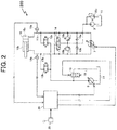
- FIG. 2 is a view depicting a standby state of a drive system incorporated in the hydraulic excavator depicted in FIG. 1 .
- the boom cylinder 4, the arm cylinder 5, and the bucket cylinder 6 depicted in FIG. 1 are depicted by a hydraulic cylinder 10 as a representative.
- the drive system 200 includes a closed circuit pump (first hydraulic pump) 7, an open circuit pump (second hydraulic pump) 8, a charge pump 9, a hydraulic cylinder 10, a fluid tank 11, a cap side selector valve 12a, a rod side selector valve 12b, a proportional valve 13, a flushing valve 14, an operation lever 30, and a controller 20.
- the closed circuit pump 7 that is a bidirectionally tiltable variable displacement pump, the open circuit pump 8 that is a unidirectionally tiltable variable displacement pump, and the charge pump 9 that is a unidirectionally tiltable fixed displacement pump are driven by a prime mover not depicted.
- the closed circuit pump 7 is connected at one delivery port thereof to a cap chamber 10a of the hydraulic cylinder 10 through a cap side hydraulic line 17a and at another delivery port thereof to a rod chamber 10b of the hydraulic cylinder 10 through a rod side hydraulic line 17b.
- the closed circuit pump 7 directly drives the hydraulic cylinder 10 by sucking fluid from one of the cap chamber 10a and the rod chamber 10b of the arm cylinder 5 and delivering the fluid to the other of the cap chamber 10a and the rod chamber 10b.
- the closed circuit pump 7, the hydraulic cylinder 10, the cap side hydraulic line 17a, and the rod side hydraulic line 17b configure a closed circuit.
- a cap side pressure sensor (cap pressure sensor) 18a for detecting the pressure of the cap chamber 10a (cap pressure) is provided, and in the rod side hydraulic line 17b, a rod side pressure sensor (rod pressure sensor) 18b for detecting the pressure of the rod chamber 10b (cap pressure) is provided.
- the open circuit pump 8 is connected at a delivery port thereof to the cap side hydraulic line 17a through the cap side selector valve 12a and to the rod side hydraulic line 17b through the rod side selector valve 12b.
- the delivery port of the open circuit pump 8 and the cap chamber 10a are communicated with each other or the communication is interrupted
- the rod side selector valve 12b performs an on or off action
- the delivery port of the open circuit pump 8 and the rod chamber 10b are communicated with each other or the communication is interrupted.
- the open circuit pump 8 sucks fluid from the fluid tank 11 and supplies hydraulic fluid to the cap chamber 10a or the rod chamber 10b of the arm cylinder 5 through the selector valve 12a or 12b.
- the proportional valve 13 is provided in a discharge hydraulic line 19 that is branched from the delivery hydraulic line of the open circuit pump 8 and is communicated with the fluid tank 11.
- the proportional valve 13 opens when the open circuit pump 8 is not used such that a delivery flow rate of the open circuit pump 8 is returned to the fluid tank 11. Further, the proportional valve 13 changes an opening area thereof continuously according to an operation amount of the operation lever 30 and adjusts a flow rate discharged from the cap chamber 10a to the fluid tank 11 to speed up a cylinder contraction action.
- the charge pump 9 sucks fluid from the fluid tank 11 and supplements the circuitry with the fluid through a check valve 15a or 15b.
- the flushing valve 14 discharges surplus fluid of one of the cap side hydraulic line 17a and the rod side hydraulic line 17b, that is the low pressure side, to the fluid tank 11.
- Main relief valves 16a and 16b set a maximum pressure for the circuitry, and a charge relief valve 16c sets a maximum pressure for the charge pump 9.
- the controller 20 calculates, on the basis of the operation amount of the operation lever 30, pressure information of the pressure sensors 18a and 18b, and so forth, and outputs a delivery direction of the closed circuit pump 7, delivery flow rate commands for the closed circuit pump 7 and the open circuit pump 8, opening-closing commands for the selector valves 12a and 12b, and an opening command for the proportional valve 13.
- the selector valve 12a in the standby state, is in a closed position and keeps the pressure in the cap chamber 10a. Meanwhile, the proportional valve 13 is in an open position and lets a standby flow rate of the open circuit pump 8 escape to the fluid tank 11 to prevent an increase of the pressure.
- the closed circuit pump 7 sucks fluid from the rod side hydraulic line 17b and delivers the fluid to the cap side hydraulic line 17a. Further, the selector valve 12a is placed into its open position and the proportional valve 13 is placed into its closed position. Then, to the open circuit pump 8, a flow rate command for making up for the shortage of fluid in the cap chamber 10a caused by a delivery flow rate of the closed circuit pump 7 and the cylinder pressure receiving area difference is issued. Consequently, the cylinder extension action can be speeded up and flow rate balance of the circuitry can be anticipated.
- the closed circuit pump 7 sucks fluid from the cap side hydraulic line 17a and delivers the fluid to the rod side hydraulic line 17b. Further, the selector valve 12a is placed into its open position, and the proportional valve 13 is opened according to the operation amount of the operation lever 30 such that a surplus flow rate discharged from the cap chamber 10a is discharged from the proportional valve 13. Consequently, the cylinder contraction action can be speeded up, and flow rate balance of the circuitry can be anticipated.
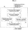
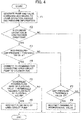
- FIG. 3 is a functional block diagram of the controller 20, and FIG. 4 is a flow chart depicting a flow of processing in one control cycle of the controller.
- the controller 20 includes a valve and pump command generation section 21, a rod assist permission decision section 22, a proportional valve opening restriction section 23, a rod assist flow rate restriction section 24, and a valve and pump command correction section 25.
- the controller 20 is configured from a CPU as a calculation section not depicted, a ROM and a RAM as storage sections, and other peripheral circuits and implements functions of various members by executing a program stored in the ROM by the CPU.
- the valve and pump command generation section 21 generates a valve command and a pump command according to an operation amount of the operation lever 30 and pressure information of the pressure sensors 18a and 18b.
- a next process F2 it is decided whether or not a cylinder action direction is a contraction direction.
- the processing advances to a process F3, but in any other case, the processing flow is ended.
- the rod assist permission decision section 22 performs a decision of whether or not a rod assist action for connecting the open circuit pump 8 to the rod chamber 10b to speed up a dumping action is to be started. For the decision, the cylinder pressure information is used.
- the rod assist permission decision section 22 decides that the open circuit pump 8 may be connected to the rod chamber 10b, and the processing advances to a process F4, but in any other case, the processing advances to a process F7.
- the threshold value ⁇ is set to a value higher than a selection setting pressure ⁇ of the flushing valve 14.
- the rod assist flow rate restriction section 24 performs calculation for suppressing a passing flow rate of the flushing valve 14 in order to suppress an increase of a rod pressure that increases as a result of the connection of the open circuit pump 8 to the rod chamber 10b.
- the rod assist flow rate restriction section 24 decides whether or not a scheduled passing flow rate value of the flushing valve 14 calculated from the pump flow rate command is greater than a permissible passing flow rate value set in advance. In the case where the scheduled passing flow rate value is greater, the processing advances to a process F6, in which the flow rate command for the open circuit pump 8 is restricted.
- the valve and pump command correction section 25 corrects the delivery flow rate command for the open circuit pump 8 generated by the valve and pump command generation section 21 in response to the flow rate command restricted by the rod assist flow rate restriction section 24. In the case where the scheduled passing flow rate value is equal to or lower than the permissible passing flow rate value, the processing flow is ended.
- the processing advances to a process F7 without performing the rod assist action.
- the proportional valve opening restriction section 23 decides whether or not the pressure of the rod chamber 10b is lower than a threshold value set in advance.
- the processing advances to a process F8, where the opening command for the proportional valve 13 is restricted.
- the valve and pump command correction section 25 corrects the opening command for the proportional valve 13 generated by the valve and pump command generation section 21 in response to the opening command restricted by the proportional valve opening restriction section 23.
- the processing flow is ended.
- valve and pump command correction section 25 corrects and outputs the commands to the valves and the pumps.
- An action of the hydraulic excavator 100 according to the present working example is described taking an action of dumping from a state in which the arm 2 is crowded in the air as an example.
- commands for the pumps and the valves are generated according to a lever operation amount and a cylinder load pressure.
- a delivery flow rate command to the rod side hydraulic line 17b is generated according to an operation amount of the operation lever 30;
- an opening command is generated;
- to the selector valve 12b a closing command is generated; and
- to the proportional valve 13 an opening command according to the command to the closed circuit pump 7 is generated.
- a state of the drive system 200 in the case where it is decided in the process F3 that the differential pressure obtained by subtracting the cap pressure from the rod pressure is equal to or lower than the threshold value ⁇ (that is, when a rod assist action is not performed) is depicted in FIG. 5 .
- the delivery flow rate of the closed circuit pump 7 is represented by Qcp and the discharge flow rate of the proportional valve 13 is represented by Qbv
- the flow rate that flows out from the cap chamber 10a is Qcp + Qbv
- the pressure receiving areas of the cap chamber 10a and the rod chamber 10b are represented by Ac and Ar, respectively, then the flow rate that flows into the rod chamber 10b is given by [Expression 1] Ar / Ac ⁇ Qcp + Qbv
- a command for connecting the open circuit pump 8 to the rod chamber 10b is generated.
- a command for closing the selector valve 12a, opening the selector valve 12b, and closing the proportional valve 13 is generated. Consequently, it becomes possible to feed the delivery flow rate of the open circuit pump 8 into the rod chamber 10b to speed up the arm dumping action.
- FIG. 6 is a view depicting an example of calculation of the rod assist permission decision section 22.
- the delivery flow rate of the closed circuit pump 7 in a state in which the open circuit pump 8 is connected to the rod chamber 10b, namely, immediately before the proportional valve 13 is closed is represented as Qcp.
- the flushing valve 14 is in its neutral position.
- the proportional valve 13 is closed at time t2 at which the differential pressure obtained by subtracting the cap pressure from the rod pressure coincides with the threshold value ⁇ as depicted in FIG. 6 .
- the threshold value ⁇ is set to a value higher than the selection setting pressure ⁇ of the flushing valve 14 and, at time t2, the flushing valve 14 is displaced sufficiently so as to open to the cap side hydraulic line 17a, the flow rate Qcp from the cap chamber 10a can be discharged by the flushing valve 14, and excessive increase of the cap pressure can be suppressed.
- the passing flow rate of the flushing valve 14 is the sum of the flow rate of the closed circuit pump 7 and twice the flow rate of the open circuit pump 8.
- the passing flow rate of the flushing valve 14 increases, then the pressure loss of the flushing valve 14 increases and the cap pressure increases. If the cap pressure increases, then the hydraulic force for displacing the flushing valve 14 to the opening side decreases, the cap side opening area of the flushing valve 14 decreases. This amplifies the pressure loss, and the displacement of the flushing valve 14 is reversed and the cylinder action becomes unstable.
- the rod assist flow rate restriction section 24 calculates whether or not the scheduled passing flow rate of the flushing valve 14 is higher than the permissible passing flow rate.
- the scheduled passing flow rate is represented by the expression (5).
- the permissible passing flow rate is set in advance as a flow rate that can be fed to the flushing valve 14 with respect to the differential pressure obtained by subtracting the cap pressure from the rod pressure.
- the axis of abscissa of FIG. 8 indicates the differential pressure obtained by subtracting the cap pressure from the rod pressure, and the axis of ordinate indicates the passing flow rate of the flushing valve 14.
- a solid line 91 indicates the permissible passing flow rate of the flushing valve 14, and a dash-dot line 92 indicates the scheduled passing flow rate of the flushing valve 14.
- the flushing valve 14 is opened to the cap side hydraulic line 17a and the permissible passing flow rate 91 increases according to the differential pressure.
- the scheduled passing flow rate 92 increases according to the differential pressure, and when the differential pressure is lower than y, the scheduled passing flow rate 92 is higher than the permissible passing flow rate 91, and when the differential pressure is higher than ⁇ , the scheduled passing flow rate 92 is lower than the permissible passing flow rate 91. Accordingly, when the differential pressure is higher than ⁇ (after time t3 depicted in FIG. 6 ), since the scheduled passing flow rate 92 is lower than the permissible passing flow rate 91, the processing flow is ended by the process F5.
- the scheduled passing flow rate indicated by the expression (5) is discharged to the fluid tank 11 through the flushing valve 14.
- the processing advances to the process F6, where the delivery flow rate of the open circuit pump 8 is restricted. Consequently, since the scheduled passing flow rate is suppressed so as to be equal to or lower than the permissible passing flow rate, an excessively high flow rate equal to or higher than a presupposed level is not fed to the flushing valve 14, and the displacement of the flushing valve 14 and the cap pressure can be stabilized.
- the permissible passing flow rate is designed using such parameters as a driving pressure-displacement characteristic, a displacement-opening characteristic, a flow rate-pressure loss characteristic upon opening of the flushing valve 14 and a permissible upper limit value of the cap pressure so as to achieve balance between the cylinder speedup and the stabilized action.
- the rod assist action is disabled when the cap chamber 10a of the hydraulic cylinder 10 is not communicated with the fluid tank 11 through the flushing valve 14, and the rod assist action is enabled when the cap chamber 10a is communicated with the fluid tank 11 through the flushing valve 14. Consequently, immediately after the rod assist action is started, part of a discharge flow rate of the cap chamber 10a begins to be returned to the fluid tank 11 through the flushing valve 14 and increase of the cap pressure is suppressed. Consequently, the contraction action of the hydraulic cylinder 10 can be speeded up stably.
- the delivery flow rate of the open circuit pump 8 is restricted such that the surplus flow rate (scheduled passing flow rate) of the cap side hydraulic line is suppressed to a level equal to or lower than the permissible passing flow rate of the flushing valve 14, and therefore, increase of the cap pressure can be suppressed further.
- a second working example of the present invention described below is directed to a case in which it is decided in the process F7 of FIG. 4 that the cap pressure of the hydraulic cylinder 10 is lower than the threshold value.
- the cylinder speed is controlled with the discharge flow rate of the cap chamber 10a (total flow rate of the suction flow rate of the closed circuit pump 7 and the discharge flow rate of the proportional valve 13).
- the proportional valve opening restriction section 23 (depicted in FIG. 4 ) restricts the opening of the proportional valve 13 in the case where the cap pressure becomes lower than the predetermined threshold value ⁇ .
- the threshold value for example, a set pressure of the charge relief valve 16c is applicable. Since this suppresses the opening of the proportional valve 13 such that the cap pressure does not become lower than the threshold value, occurrence of cavitation described above can be prevented.
- the present invention is not limited to the embodiment described above but includes various modifications.
- the embodiment is described above taking a hydraulic excavator as an example, the present invention can be applied also to the construction machines other than the hydraulic excavator.
- the embodiment described above has been described in detail in order to facilitate understanding of the present invention, the present invention does not necessarily need to include all components described hereinabove.
Landscapes
- Engineering & Computer Science (AREA)
- General Engineering & Computer Science (AREA)
- Mining & Mineral Resources (AREA)
- Civil Engineering (AREA)
- Structural Engineering (AREA)
- Physics & Mathematics (AREA)
- Fluid Mechanics (AREA)
- Mechanical Engineering (AREA)
- Fluid-Pressure Circuits (AREA)
- Operation Control Of Excavators (AREA)
Abstract
Description
- The present invention relates to a construction machine that includes a hydraulic closed circuit in which a hydraulic actuator is driven directly by a hydraulic pump.
- In recent years, energy saving is an important development item in a construction machine such as a hydraulic excavator or a wheel loader. For energy saving of a construction machine, energy saving of a hydraulic system is effective. Therefore, application of a hydraulic circuit (hereinafter referred to as "hydraulic closed circuit") that connects a hydraulic pump of the bidirectionally tiltable type and a hydraulic actuator to each other without a throttle valve interposed therebetween such that the hydraulic actuator is directly driven by the hydraulic pump is under consideration. In the hydraulic closed circuit, since pressure loss by a throttle valve does not occur and the hydraulic pump delivers only a flow rate required by the hydraulic actuator, flow rate loss by shunting does not occur. Therefore, a hydraulic system to which the hydraulic closed circuit is applied can achieve energy saving rather than a conventional hydraulic system.
- A hydraulic closed circuit is disclosed, for example, in
Patent Document 1.Patent Document 1 discloses a drive system for a work machine in which a fluid pressure actuator (hereinafter referred to as single rod hydraulic cylinder) and a bidirectionally tiltable variable displacement pump (hereinafter referred to as open circuit pump) are directly coupled to each other, and hydraulic fluid of a unidirectionally tiltable variable displacement pump (hereinafter referred to as closed circuit pump) can be supplied into a bottom chamber (hereinafter referred to as cap chamber) or a rod chamber of the single rod hydraulic cylinder. The hydraulic closed circuit includes a flushing valve that communicates the low pressure side of two hydraulic lines (hereinafter referred to as a cap side hydraulic line and a rod side hydraulic line) for connecting the closed circuit pump and the single rod hydraulic cylinder to each other with an fluid tank to absorb a flow rate difference between the cap side hydraulic line and the rod side hydraulic line. - Patent Document 1:
JP-2005-76781-A - According to the drive system for a work machine disclosed in
Patent Document 1, a cylinder contraction action can be speeded up by supplying hydraulic fluid of the open circuit pump into the rod chamber of the single rod hydraulic cylinder (rod assist action). - However, depending upon the timing at which a rod assist action is started, the cap side hydraulic line is not communicated as yet with the fluid tank through the flushing valve and surplus fluid of the cap side hydraulic line cannot be returned into the fluid tank through the flushing valve. As a result, the pressure (back pressure) in the cap chamber increases excessively, resulting in the possibility that the cylinder contraction action cannot be speeded up stably.
- The present invention has been made in view of such a problem as described above, and the object of the present invention resides in provision of a construction machine including a hydraulic closed circuit in which a single rod hydraulic cylinder is driven directly by a bidirectionally tiltable variable displacement pump and can stably speed up the contraction action of the single rod hydraulic cylinder.
- In order to achieve the object described above, according to the present invention, there is provided a construction machine including: a single rod hydraulic cylinder having a cap chamber and a rod chamber; a first hydraulic pump that is a bidirectionally tiltable variable displacement pump; a cap side hydraulic line that connects one delivery port of the first hydraulic pump and the cap chamber to each other; a rod side hydraulic line that connects another delivery port of the first hydraulic pump and the rod chamber to each other; a fluid tank; a flushing valve that discharges surplus fluid of one of the cap side hydraulic line and the rod side hydraulic line, that one is on a low pressure side, to the fluid tank; a second hydraulic pump that is a unidirectionally tiltable variable displacement pump; a rod side selector valve that communicates a delivery port of the second hydraulic pump and the rod chamber with each other or interrupts the communication; an operation lever for instructing an action of the hydraulic cylinder; a cap pressure sensor that detects a pressure of the cap chamber; a rod pressure sensor that detects a pressure of the rod chamber; and a controller for controlling the first hydraulic pump, the second hydraulic pump, and the rod side selector valve based on inputs from the operation lever, the cap pressure sensor, and the rod pressure sensor. The controller is configured to, in a case where a contraction action of the hydraulic cylinder is instructed through the operation lever, close the rod side selector valve to disable a rod assist action for supplying hydraulic fluid from the second hydraulic pump to the rod chamber when a differential pressure obtained by subtracting the pressure of the cap chamber from the pressure of the rod chamber is equal to or lower than a first threshold value set to a level equal to or higher than a selection setting pressure of the flushing valve, and open the rod side selector valve to enable the rod assist action when the differential pressure is higher than the first threshold value.
- According to the present invention configured in such a manner as described above, in the case where the single rod hydraulic cylinder is operated in the contraction direction, when the cap chamber of the single rod hydraulic cylinder is not communicated with the fluid tank through the flushing valve, the rod assist action is disabled, and when the cap chamber is communicated with the fluid tank through the flushing valve, the rod assist action is enabled. Consequently, immediately after the rod assist action is started, part of the discharge flow rate of the cap chamber begins to be returned to the fluid tank through the flushing valve, and therefore, increase of the cap pressure is suppressed. As a result, it becomes possible to stably speed up the contraction action of the single rod hydraulic cylinder.
- According to the present invention, it is possible, in a construction machine that includes a hydraulic closed circuit in which a single rod hydraulic cylinder is directly driven by a bidirectionally tiltable variable displacement pump, to speed up the contraction action of the single rod hydraulic cylinder stably.
-
-
FIG. 1 is a side elevational view of a hydraulic excavator as an example of a construction machine according to an embodiment of the present invention. -
FIG. 2 is a view depicting a standby state of a drive system incorporated in the hydraulic excavator depicted inFIG. 1 . -
FIG. 3 is a functional block diagram of a controller depicted inFIG. 2 . -
FIG. 4 is a flow chart depicting a flow of processing in one control cycle of the controller depicted inFIG. 2 . -
FIG. 5 is a view depicting a state when a rod assist action of the drive system depicted inFIG. 2 is not being performed. -
FIG. 6 is a view depicting an example of calculation of a rod assist permission decision section depicted inFIG. 3 . -
FIG. 7 is a view depicting a state when a rod assist action of the drive system depicted inFIG. 2 is being performed. -
FIG. 8 is a view depicting an example of calculation of a rod assist flow rate restriction section depicted inFIG. 3 . - In the following, a construction machine according to an embodiment of the present invention is described with reference to the drawings taking a hydraulic excavator as an example. It is to be noted that like members in the figures are denoted by like reference characters and overlapping description of them is suitably omitted herein.
-
FIG. 1 is a side elevational view of the hydraulic excavator according to the present embodiment. - As depicted in
FIG. 1 , ahydraulic excavator 100 includes alower track structure 1C, anupper swing structure 1B mounted for swinging motion on thelower track structure 1C, and afront implement 1A attached for pivotal motion in upward and downward directions to the front side of theupper swing structure 1B. Thelower track structure 1C is driven to travel by a traveling motor not depicted, and theupper swing structure 1B is driven to swing by a swing motor not depicted. - The
front implement 1A includes aboom 1, anarm 2, abucket 3, a single rodhydraulic cylinder 4, another single rodhydraulic cylinder 5, and a further single rodhydraulic cylinder 6. Theboom 1 is attached at a proximal end portion thereof for pivotal motion in upward and downward directions at a front portion of theupper swing structure 1B. Thearm 2 is attached for pivotal motion in upward and downward directions and forward and rearward directions to a distal end portion of theboom 1. Thebucket 3 is attached for pivotal motion in upward and downward directions and forward and rearward directions to a distal end portion of thearm 2. The single rod hydraulic cylinder (hereinafter referred to as "boom cylinder") 4 drives theboom 1. The single rod hydraulic cylinder (hereinafter referred to as "arm cylinder") 5 drives thearm 2. The single rod hydraulic cylinder (hereinafter referred to as "bucket cylinder") 6 drives thebucket 3. In a cab of thehydraulic excavator 100, an operation lever 30 (depicted inFIG. 2 ) for instructing actions for thehydraulic cylinders 4 to 7 is installed. - A first working example of the present invention is described with reference to
FIGS. 2 to 8 . -
FIG. 2 is a view depicting a standby state of a drive system incorporated in the hydraulic excavator depicted inFIG. 1 . InFIG. 2 , theboom cylinder 4, thearm cylinder 5, and thebucket cylinder 6 depicted inFIG. 1 are depicted by ahydraulic cylinder 10 as a representative. - As depicted in
FIG. 2 , thedrive system 200 includes a closed circuit pump (first hydraulic pump) 7, an open circuit pump (second hydraulic pump) 8, acharge pump 9, ahydraulic cylinder 10, afluid tank 11, a capside selector valve 12a, a rodside selector valve 12b, aproportional valve 13, aflushing valve 14, anoperation lever 30, and acontroller 20. - The closed
circuit pump 7 that is a bidirectionally tiltable variable displacement pump, theopen circuit pump 8 that is a unidirectionally tiltable variable displacement pump, and thecharge pump 9 that is a unidirectionally tiltable fixed displacement pump are driven by a prime mover not depicted. - The closed
circuit pump 7 is connected at one delivery port thereof to acap chamber 10a of thehydraulic cylinder 10 through a cap sidehydraulic line 17a and at another delivery port thereof to arod chamber 10b of thehydraulic cylinder 10 through a rod sidehydraulic line 17b. The closedcircuit pump 7 directly drives thehydraulic cylinder 10 by sucking fluid from one of thecap chamber 10a and therod chamber 10b of thearm cylinder 5 and delivering the fluid to the other of thecap chamber 10a and therod chamber 10b. In other words, theclosed circuit pump 7, thehydraulic cylinder 10, the cap sidehydraulic line 17a, and the rod sidehydraulic line 17b configure a closed circuit. In the cap sidehydraulic line 17a, a cap side pressure sensor (cap pressure sensor) 18a for detecting the pressure of thecap chamber 10a (cap pressure) is provided, and in the rod sidehydraulic line 17b, a rod side pressure sensor (rod pressure sensor) 18b for detecting the pressure of therod chamber 10b (cap pressure) is provided. - The
open circuit pump 8 is connected at a delivery port thereof to the cap sidehydraulic line 17a through the capside selector valve 12a and to the rod sidehydraulic line 17b through the rodside selector valve 12b. When the capside selector valve 12a performs an on or off action, the delivery port of theopen circuit pump 8 and thecap chamber 10a are communicated with each other or the communication is interrupted, and when the rodside selector valve 12b performs an on or off action, the delivery port of theopen circuit pump 8 and therod chamber 10b are communicated with each other or the communication is interrupted. Theopen circuit pump 8 sucks fluid from thefluid tank 11 and supplies hydraulic fluid to thecap chamber 10a or therod chamber 10b of thearm cylinder 5 through theselector valve - The
proportional valve 13 is provided in a dischargehydraulic line 19 that is branched from the delivery hydraulic line of theopen circuit pump 8 and is communicated with thefluid tank 11. Theproportional valve 13 opens when theopen circuit pump 8 is not used such that a delivery flow rate of theopen circuit pump 8 is returned to thefluid tank 11. Further, theproportional valve 13 changes an opening area thereof continuously according to an operation amount of theoperation lever 30 and adjusts a flow rate discharged from thecap chamber 10a to thefluid tank 11 to speed up a cylinder contraction action. Thecharge pump 9 sucks fluid from thefluid tank 11 and supplements the circuitry with the fluid through acheck valve valve 14 discharges surplus fluid of one of the cap sidehydraulic line 17a and the rod sidehydraulic line 17b, that is the low pressure side, to thefluid tank 11.Main relief valves charge relief valve 16c sets a maximum pressure for thecharge pump 9. - The
controller 20 calculates, on the basis of the operation amount of theoperation lever 30, pressure information of thepressure sensors closed circuit pump 7, delivery flow rate commands for theclosed circuit pump 7 and theopen circuit pump 8, opening-closing commands for theselector valves proportional valve 13. - As depicted in
FIG. 2 , in the standby state, theselector valve 12a is in a closed position and keeps the pressure in thecap chamber 10a. Meanwhile, theproportional valve 13 is in an open position and lets a standby flow rate of theopen circuit pump 8 escape to thefluid tank 11 to prevent an increase of the pressure. - Now, an arm action is described.
- In an extension action of the
hydraulic cylinder 10, theclosed circuit pump 7 sucks fluid from the rod sidehydraulic line 17b and delivers the fluid to the cap sidehydraulic line 17a. Further, theselector valve 12a is placed into its open position and theproportional valve 13 is placed into its closed position. Then, to theopen circuit pump 8, a flow rate command for making up for the shortage of fluid in thecap chamber 10a caused by a delivery flow rate of theclosed circuit pump 7 and the cylinder pressure receiving area difference is issued. Consequently, the cylinder extension action can be speeded up and flow rate balance of the circuitry can be anticipated. - In a contraction action of the
hydraulic cylinder 10, theclosed circuit pump 7 sucks fluid from the cap sidehydraulic line 17a and delivers the fluid to the rod sidehydraulic line 17b. Further, theselector valve 12a is placed into its open position, and theproportional valve 13 is opened according to the operation amount of theoperation lever 30 such that a surplus flow rate discharged from thecap chamber 10a is discharged from theproportional valve 13. Consequently, the cylinder contraction action can be speeded up, and flow rate balance of the circuitry can be anticipated. -
FIG. 3 is a functional block diagram of thecontroller 20, andFIG. 4 is a flow chart depicting a flow of processing in one control cycle of the controller. - As depicted in
FIG. 3 , thecontroller 20 includes a valve and pumpcommand generation section 21, a rod assistpermission decision section 22, a proportional valveopening restriction section 23, a rod assist flowrate restriction section 24, and a valve and pumpcommand correction section 25. Thecontroller 20 is configured from a CPU as a calculation section not depicted, a ROM and a RAM as storage sections, and other peripheral circuits and implements functions of various members by executing a program stored in the ROM by the CPU. - In a process F1 of
FIG. 4 , the valve and pumpcommand generation section 21 generates a valve command and a pump command according to an operation amount of theoperation lever 30 and pressure information of thepressure sensors permission decision section 22 performs a decision of whether or not a rod assist action for connecting theopen circuit pump 8 to therod chamber 10b to speed up a dumping action is to be started. For the decision, the cylinder pressure information is used. If the differential pressure obtained by subtracting the pressure of thecap chamber 10a from the pressure of therod chamber 10b is higher than a predetermined threshold value (first threshold value) α, then the rod assistpermission decision section 22 decides that theopen circuit pump 8 may be connected to therod chamber 10b, and the processing advances to a process F4, but in any other case, the processing advances to a process F7. Here, the threshold value α is set to a value higher than a selection setting pressure β of the flushingvalve 14. - In the process F4 in the case where a rod assist action is performed, a command for connecting the
open circuit pump 8 to therod chamber 10b is generated. Then in a next process F5, the rod assist flowrate restriction section 24 performs calculation for suppressing a passing flow rate of the flushingvalve 14 in order to suppress an increase of a rod pressure that increases as a result of the connection of theopen circuit pump 8 to therod chamber 10b. In particular, the rod assist flowrate restriction section 24 decides whether or not a scheduled passing flow rate value of the flushingvalve 14 calculated from the pump flow rate command is greater than a permissible passing flow rate value set in advance. In the case where the scheduled passing flow rate value is greater, the processing advances to a process F6, in which the flow rate command for theopen circuit pump 8 is restricted. The valve and pumpcommand correction section 25 corrects the delivery flow rate command for theopen circuit pump 8 generated by the valve and pumpcommand generation section 21 in response to the flow rate command restricted by the rod assist flowrate restriction section 24. In the case where the scheduled passing flow rate value is equal to or lower than the permissible passing flow rate value, the processing flow is ended. - In the case where it is decided by the process F3 that the differential pressure obtained by subtracting the pressure of the
cap chamber 10a from the pressure of therod chamber 10b is equal to or lower than the threshold value α, the processing advances to a process F7 without performing the rod assist action. In the process F7, the proportional valveopening restriction section 23 decides whether or not the pressure of therod chamber 10b is lower than a threshold value set in advance. In the case where the pressure of therod chamber 10b is lower than the threshold value, the processing advances to a process F8, where the opening command for theproportional valve 13 is restricted. The valve and pumpcommand correction section 25 corrects the opening command for theproportional valve 13 generated by the valve and pumpcommand generation section 21 in response to the opening command restricted by the proportional valveopening restriction section 23. In the case where the differential pressure is higher than the threshold value α, the processing flow is ended. - On the basis of the command after such restrictions, the valve and pump
command correction section 25 corrects and outputs the commands to the valves and the pumps. - An action of the
hydraulic excavator 100 according to the present working example is described taking an action of dumping from a state in which thearm 2 is crowded in the air as an example. - In the process F1, commands for the pumps and the valves are generated according to a lever operation amount and a cylinder load pressure. As described hereinabove, to the
closed circuit pump 7, a delivery flow rate command to the rod sidehydraulic line 17b is generated according to an operation amount of theoperation lever 30; to theselector valve 12a, an opening command is generated; to theselector valve 12b, a closing command is generated; and to theproportional valve 13, an opening command according to the command to theclosed circuit pump 7 is generated. - In the process F2, decision of whether or not the cylinder operation direction is the contraction direction is performed. Since the arm dumping action corresponds to the cylinder contraction direction, the processing advances to the process F3. In the next process F3, it is decided whether or not the differential pressure obtained by subtracting the pressure of the
cap chamber 10a from the pressure of therod chamber 10b is higher than the positive threshold value α. Since, in the posture in which thearm 2 is crowded, the pressure of thecap chamber 10a is sufficiently higher than the pressure of therod chamber 10b, the decision criterion of the process F3 is not satisfied, and the processing advances to the process F7. In the process F7, it is decided whether or not the pressure of thecap chamber 10a is lower than a predetermined threshold value (second threshold value) δ. In the present working example, it is decided that the decision criterion is not satisfied, and the processing flow is ended. An action in the case where it is decided that the cap pressure is lower than the threshold value δ and the process F8 is performed is described in the description of a second working example. - A state of the
drive system 200 in the case where it is decided in the process F3 that the differential pressure obtained by subtracting the cap pressure from the rod pressure is equal to or lower than the threshold value α (that is, when a rod assist action is not performed) is depicted inFIG. 5 . If the delivery flow rate of theclosed circuit pump 7 is represented by Qcp and the discharge flow rate of theproportional valve 13 is represented by Qbv, then since the flow rate that flows out from thecap chamber 10a is Qcp + Qbv, if the pressure receiving areas of thecap chamber 10a and therod chamber 10b are represented by Ac and Ar, respectively, then the flow rate that flows into therod chamber 10b is given by
[Expression 1]
- Here, since the
closed circuit pump 7 delivers, simultaneously when it sucks the flow rate of Qcp from thecap chamber 10a, an equal flow rate of fluid to therod chamber 10b, the flow rate passing the flushingvalve 14 is given by
[Expression 2]
- Here, if Ar = 1 and Ac = 2 are assumed for the simplified description, then the expression (2) is represented as
[Expression 3]
- Thus, it can be recognized that the flow rates of the
proportional valve 13 and theclosed circuit pump 7 cancel each other, resulting in the passing flow rate of the flushingvalve 14. Therefore, the pressure loss of the flushingvalve 14 is small and the rod pressure tends to be less likely to increase. For example, if Qcp = 100 and Qbv = 100 are satisfied, then the value of the expression (2) becomes zero and no fluid flows through the flushingvalve 14. - If the arm dumping action continues and the own weight acts in the cylinder contraction direction until the differential pressure obtained by subtracting the cap pressure from the rod pressure becomes higher than the threshold value α, then the processing advances to the process F4 as a result of the decision in the process F3.
- In the process F4, a command for connecting the
open circuit pump 8 to therod chamber 10b is generated. In particular, a command for closing theselector valve 12a, opening theselector valve 12b, and closing theproportional valve 13 is generated. Consequently, it becomes possible to feed the delivery flow rate of theopen circuit pump 8 into therod chamber 10b to speed up the arm dumping action. - Here, the reason why the threshold value α is provided in the process F3 is described with reference to
FIGS. 5 and6. FIG. 6 is a view depicting an example of calculation of the rod assistpermission decision section 22. - Referring to
FIG. 5 , the delivery flow rate of theclosed circuit pump 7 in a state in which theopen circuit pump 8 is connected to therod chamber 10b, namely, immediately before theproportional valve 13 is closed, is represented as Qcp. At this time, if theproportional valve 13 is closed at time t1 at which the pressure of therod chamber 10b and the pressure of thecap chamber 10a are equal to each other, then since Qbv = 0 is satisfied, the discharge flow rate from thecap chamber 10a becomes Qcp. On the other hand, since the pressures of therod chamber 10b and thecap chamber 10a are equal to each other, the flushingvalve 14 is in its neutral position. Therefore, the discharge flow rate Qcp from thecap chamber 10a cannot be discharged from the flushingvalve 14 to thefluid tank 11, and the cap pressure increases. Consequently, the displacement of the flushingvalve 14 is returned so as to open to the rod sidehydraulic line 17b, resulting in instability of the cylinder action. - Therefore, the
proportional valve 13 is closed at time t2 at which the differential pressure obtained by subtracting the cap pressure from the rod pressure coincides with the threshold value α as depicted inFIG. 6 . Here, since the threshold value α is set to a value higher than the selection setting pressure β of the flushingvalve 14 and, at time t2, the flushingvalve 14 is displaced sufficiently so as to open to the cap sidehydraulic line 17a, the flow rate Qcp from thecap chamber 10a can be discharged by the flushingvalve 14, and excessive increase of the cap pressure can be suppressed. - When the
open circuit pump 8 is connected to therod chamber 10b in this manner, the circuit state transitions to that ofFIG. 7 . Where the delivery flow rate of theclosed circuit pump 7 is represented by Qcp and the delivery flow rate of theopen circuit pump 8 is represented by Qop, since the flow rate flowing into therod chamber 10b becomes Qcp + Qop, the flow rate discharged from thecap chamber 10a is given by
[Expression 4]
- Since, simultaneously when the
closed circuit pump 7 delivers the flow rate of Qcp to therod chamber 10b, it sucks an equal flow rate from thecap chamber 10a, the flow rate passing the flushingvalve 14 is given by
[Expression 5]
- If Ar = 1 and Ac = 2 are assumed for the simplified description, then the expression (5) is represented as
[Expression 6]
- Thus, it can be recognized that the passing flow rate of the flushing
valve 14 is the sum of the flow rate of theclosed circuit pump 7 and twice the flow rate of theopen circuit pump 8. Incidentally, if the passing flow rate of the flushingvalve 14 increases, then the pressure loss of the flushingvalve 14 increases and the cap pressure increases. If the cap pressure increases, then the hydraulic force for displacing the flushingvalve 14 to the opening side decreases, the cap side opening area of the flushingvalve 14 decreases. This amplifies the pressure loss, and the displacement of the flushingvalve 14 is reversed and the cylinder action becomes unstable. - Therefore, calculation by the rod assist flow
rate restriction section 24 is performed. In the process F5, decision of whether or not the scheduled passing flow rate of the flushingvalve 14 is higher than the permissible passing flow rate is performed. The scheduled passing flow rate is represented by the expression (5). The permissible passing flow rate is set in advance as a flow rate that can be fed to the flushingvalve 14 with respect to the differential pressure obtained by subtracting the cap pressure from the rod pressure. - This relation is described with reference to an example of
FIG. 8 . The axis of abscissa ofFIG. 8 indicates the differential pressure obtained by subtracting the cap pressure from the rod pressure, and the axis of ordinate indicates the passing flow rate of the flushingvalve 14. Asolid line 91 indicates the permissible passing flow rate of the flushingvalve 14, and a dash-dot line 92 indicates the scheduled passing flow rate of the flushingvalve 14. When the differential pressure is lower than the selection setting pressure β of the flushingvalve 14, since the flushingvalve 14 is not open to the cap sidehydraulic line 17a, the permissible passingflow rate 91 is zero. If the differential pressure exceeds the selection setting pressure β of the flushingvalve 14, then the flushingvalve 14 is opened to the cap sidehydraulic line 17a and the permissible passingflow rate 91 increases according to the differential pressure. The scheduled passingflow rate 92 increases according to the differential pressure, and when the differential pressure is lower than y, the scheduled passingflow rate 92 is higher than the permissible passingflow rate 91, and when the differential pressure is higher than γ, the scheduled passingflow rate 92 is lower than the permissible passingflow rate 91. Accordingly, when the differential pressure is higher than γ (after time t3 depicted inFIG. 6 ), since the scheduled passingflow rate 92 is lower than the permissible passingflow rate 91, the processing flow is ended by the process F5. At this time, the scheduled passing flow rate indicated by the expression (5) is discharged to thefluid tank 11 through the flushingvalve 14. When the differential pressure is lower than γ (before time t3 depicted inFIG. 6 ), since the scheduled passingflow rate 92 is higher than the permissible passingflow rate 91, the processing advances to the process F6, where the delivery flow rate of theopen circuit pump 8 is restricted. Consequently, since the scheduled passing flow rate is suppressed so as to be equal to or lower than the permissible passing flow rate, an excessively high flow rate equal to or higher than a presupposed level is not fed to the flushingvalve 14, and the displacement of the flushingvalve 14 and the cap pressure can be stabilized. - It is to be noted that the permissible passing flow rate is designed using such parameters as a driving pressure-displacement characteristic, a displacement-opening characteristic, a flow rate-pressure loss characteristic upon opening of the flushing
valve 14 and a permissible upper limit value of the cap pressure so as to achieve balance between the cylinder speedup and the stabilized action. - With the
hydraulic excavator 100 according to the present working example configured in such a manner as described above, in the case where thehydraulic cylinder 10 is operated in the contraction direction, the rod assist action is disabled when thecap chamber 10a of thehydraulic cylinder 10 is not communicated with thefluid tank 11 through the flushingvalve 14, and the rod assist action is enabled when thecap chamber 10a is communicated with thefluid tank 11 through the flushingvalve 14. Consequently, immediately after the rod assist action is started, part of a discharge flow rate of thecap chamber 10a begins to be returned to thefluid tank 11 through the flushingvalve 14 and increase of the cap pressure is suppressed. Consequently, the contraction action of thehydraulic cylinder 10 can be speeded up stably. - Further, when the
open circuit pump 8 is connected to thecap chamber 10a in the cylinder contraction action, the delivery flow rate of theopen circuit pump 8 is restricted such that the surplus flow rate (scheduled passing flow rate) of the cap side hydraulic line is suppressed to a level equal to or lower than the permissible passing flow rate of the flushingvalve 14, and therefore, increase of the cap pressure can be suppressed further. - A second working example of the present invention described below is directed to a case in which it is decided in the process F7 of
FIG. 4 that the cap pressure of thehydraulic cylinder 10 is lower than the threshold value. In a state in which the rod assist action is not being performed (depicted inFIG. 5 ), the cylinder speed is controlled with the discharge flow rate of thecap chamber 10a (total flow rate of the suction flow rate of theclosed circuit pump 7 and the discharge flow rate of the proportional valve 13). - At this time, if the flow rate Qbv of the
proportional valve 13 becomes excessively high due to the cylinder speedup, then the cap pressure becomes excessively low and cavitation occurs on the suction side of theclosed circuit pump 7, resulting in occurrence of a disadvantage that the pump is damaged or the like. - In order to prevent this, the proportional valve opening restriction section 23 (depicted in
FIG. 4 ) restricts the opening of theproportional valve 13 in the case where the cap pressure becomes lower than the predetermined threshold value δ. As the threshold value, for example, a set pressure of thecharge relief valve 16c is applicable. Since this suppresses the opening of theproportional valve 13 such that the cap pressure does not become lower than the threshold value, occurrence of cavitation described above can be prevented. - Although the embodiment of the present invention has been described in detail, the present invention is not limited to the embodiment described above but includes various modifications. For example, although the embodiment is described above taking a hydraulic excavator as an example, the present invention can be applied also to the construction machines other than the hydraulic excavator. Further, the embodiment described above has been described in detail in order to facilitate understanding of the present invention, the present invention does not necessarily need to include all components described hereinabove.
-
- 1A:
- Front implement
- 1B:
- Upper swing structure
- 1C:
- Lower track structure
- 1:
- Boom
- 2:
- Arm
- 3:
- Bucket
- 4:
- Boom cylinder (hydraulic cylinder)
- 5:
- Arm cylinder (hydraulic cylinder)
- 6:
- Bucket cylinder (hydraulic cylinder)
- 7:
- Closed circuit pump
- 8:
- Open circuit pump
- 9:
- Charge pump
- 10:
- Hydraulic cylinder
- 10a:
- Cap chamber
- 10b:
- Rod chamber
- 11:
- Fluid tank
- 12:
- Selector valve
- 13:
- Proportional valve
- 14:
- Flushing valve
- 15:
- Check valve
- 16a,
- 16b: Main relief valve
- 16c:
- Charge relief valve
- 17a:
- Cap side hydraulic line
- 17b:
- Rod side hydraulic line
- 18a:
- Cap side pressure sensor (cap pressure sensor)
- 18b:
- Rod side pressure sensor (rod pressure sensor)
- 19:
- Discharge hydraulic line
- 20:
- Controller
- 21:
- Valve and pump command generation section
- 22:
- Rod assist permission decision section
- 23:
- Proportional valve opening restriction section
- 24:
- Rod assist flow rate restriction section
- 25:
- Valve and pump command correction section
- 30:
- Operation lever
- 91:
- Flushing valve permissible passing flow rate
- 92:
- Flushing valve scheduled passing flow rate
- 100:
- Hydraulic excavator
- 200:
- Drive system
Claims (5)
- A construction machine, comprising:a single rod hydraulic cylinder having a cap chamber and a rod chamber;a first hydraulic pump that is a bidirectionally tiltable variable displacement pump;a cap side hydraulic line that connects one delivery port of the first hydraulic pump and the cap chamber to each other;a rod side hydraulic line that connects another delivery port of the first hydraulic pump and the rod chamber to each other;a fluid tank;a flushing valve that discharges surplus fluid of one of the cap side hydraulic line and the rod side hydraulic line, that one is on a lower pressure side, to the fluid tank;a second hydraulic pump that is a unidirectionally tiltable variable displacement pump;a rod side selector valve that communicates a delivery port of the second hydraulic pump and the rod chamber with each other or interrupts the communication;an operation lever for instructing an action of the hydraulic cylinder;a cap pressure sensor that detects a pressure of the cap chamber;a rod pressure sensor that detects a pressure of the rod chamber; anda controller for controlling the first hydraulic pump, the second hydraulic pump, and the rod side selector valve based on inputs from the operation lever, the cap pressure sensor, and the rod pressure sensor, whereinthe controller is configured to, in a case where a contraction action of the hydraulic cylinder is instructed through the operation lever, close the rod side selector valve to disable a rod assist action for supplying hydraulic fluid from the second hydraulic pump to the rod chamber when a differential pressure obtained by subtracting the pressure of the cap chamber from the pressure of the rod chamber is equal to or lower than a first threshold value set to a level equal to or higher than a selection setting pressure of the flushing valve, and open the rod side selector valve to enable the rod assist action when the differential pressure is higher than the first threshold value.
- The construction machine according to claim 1, wherein the controller includes
a valve and pump command generation section that generates delivery flow rate commands for the first and second hydraulic pumps and an opening-closing command for the rod side selector valve based on inputs from the operation lever, the rod pressure sensor, and the cap pressure sensor,
a rod assist permission decision section that, in a case where a contraction action of the hydraulic cylinder is instructed through the operation lever, decides that the rod assist action is enabled when the differential pressure is equal to or lower than the first threshold value, and decides that the rod assist action is disabled when the differential pressure is higher than the first threshold value, and
a valve and pump command correction section that corrects, when the rod assist permission decision section decides that the rod assist action is enabled, the opening-closing command for the rod side selector valve generated by the valve and pump command generation section to an opening command, and corrects, when the rod assist permission decision section decides that the rod assist action is disabled, the opening-closing command for the rod side selector valve to a closing command. - The construction machine according to claim 2, wherein the controller further includes
a rod assist flow rate restriction section that calculates a delivery flow rate of the second hydraulic pump such that, when the rod assist permission decision section decides that the rod assist action is enabled and besides a scheduled passing flow rate of the flushing valve based on the delivery flow rate command for the first hydraulic pump and the delivery flow rate command for the second hydraulic pump is higher than a permissible passing flow rate of the flushing valve according to the differential pressure, the scheduled passing flow rate is equal to or lower than the permissible passing flow rate, and
the valve and pump command correction section corrects the delivery flow rate command for the second hydraulic pump generated by the valve and pump command generation section in accordance with the delivery flow rate of the second hydraulic pump calculated by the rod assist flow rate restriction section. - The construction machine according to claim 2, further comprising:a cap side selector valve that communicates the delivery port of the second hydraulic pump and the cap chamber with each other or interrupts the communication; anda proportional valve provided in a discharge hydraulic line that connects the delivery port of the second hydraulic pump and the fluid tank to each other, the proportional valve being capable of continuously adjusting an opening area, whereinthe valve and pump command correction section corrects, when the rod assist permission decision section decides that the rod assist action is disabled, the opening-closing command for the cap side selector valve generated by the valve and pump command generation section to an opening command such that discharge of fluid from the cap chamber to the fluid tank is enabled.
- The construction machine according to claim 4, wherein the controller further includes
a proportional valve opening restriction section that calculates, when the rod assist permission decision section decides that the rod assist action is enabled and besides the pressure of the cap chamber is lower than a predetermined second threshold value, such an opening area of the proportional valve that the pressure of the cap chamber becomes equal to or higher than the second threshold value, and
the valve and pump command correction section corrects an opening command for the proportional valve in accordance with the opening area of the proportional valve calculated by the proportional valve opening restriction section.
Applications Claiming Priority (1)
| Application Number | Priority Date | Filing Date | Title |
|---|---|---|---|
| PCT/JP2018/001062 WO2019142244A1 (en) | 2018-01-16 | 2018-01-16 | Construction machine |
Publications (3)
| Publication Number | Publication Date |
|---|---|
| EP3742000A1 true EP3742000A1 (en) | 2020-11-25 |
| EP3742000A4 EP3742000A4 (en) | 2021-08-18 |
| EP3742000B1 EP3742000B1 (en) | 2024-03-13 |
Family
ID=67301402
Family Applications (1)
| Application Number | Title | Priority Date | Filing Date |
|---|---|---|---|
| EP18901447.5A Active EP3742000B1 (en) | 2018-01-16 | 2018-01-16 | Construction machine |
Country Status (5)
| Country | Link |
|---|---|
| US (1) | US10858805B2 (en) |
| EP (1) | EP3742000B1 (en) |
| JP (1) | JP6814309B2 (en) |
| CN (1) | CN110366641B (en) |
| WO (1) | WO2019142244A1 (en) |
Families Citing this family (4)
| Publication number | Priority date | Publication date | Assignee | Title |
|---|---|---|---|---|
| US11001989B1 (en) | 2020-03-30 | 2021-05-11 | Caterpillar Inc. | Electrical control of a hydraulic system |
| IT202100000272A1 (en) * | 2021-01-08 | 2022-07-08 | Cnh Ind Italia Spa | CONTROL PROCEDURE FOR AUTOMATICALLY SELECTING AN OPERATING MODE OF A OPERATING MACHINE, CORRESPONDING CONTROL SYSTEM AND OPERATING MACHINE INCLUDING THE CONTROL SYSTEM |
| CN113417896B (en) * | 2021-06-04 | 2022-05-10 | 燕山大学 | Pump-controlled hydraulic system of press machine and control method thereof |
| CN114561986B (en) * | 2022-02-21 | 2023-02-03 | 徐州徐工挖掘机械有限公司 | Control method for actively preventing bucket rod from being sucked empty |
Family Cites Families (9)
| Publication number | Priority date | Publication date | Assignee | Title |
|---|---|---|---|---|
| JPS60139902A (en) * | 1983-12-28 | 1985-07-24 | Hitachi Constr Mach Co Ltd | Drive unit of flashing valve |
| JP2005076781A (en) * | 2003-09-01 | 2005-03-24 | Shin Caterpillar Mitsubishi Ltd | Drive unit of working machine |
| JP5805217B2 (en) * | 2012-01-11 | 2015-11-04 | 日立建機株式会社 | Hydraulic closed circuit drive |
| US9683588B2 (en) * | 2012-01-31 | 2017-06-20 | Hitachi Construction Machinery Co., Ltd. | Hydraulic closed circuit system |
| CN104903595B (en) * | 2013-01-08 | 2017-03-08 | 日立建机株式会社 | The hydraulic system of work mechanism |
| JP6285787B2 (en) * | 2014-04-14 | 2018-02-28 | 日立建機株式会社 | Hydraulic drive |
| JP6328548B2 (en) * | 2014-12-23 | 2018-05-23 | 日立建機株式会社 | Work machine |
| JP2016125521A (en) * | 2014-12-26 | 2016-07-11 | 日立建機株式会社 | Working machine |
| JP6383676B2 (en) * | 2015-02-06 | 2018-08-29 | 日立建機株式会社 | Work machine |
-
2018
- 2018-01-16 JP JP2019566016A patent/JP6814309B2/en not_active Expired - Fee Related
- 2018-01-16 CN CN201880015135.1A patent/CN110366641B/en not_active Expired - Fee Related
- 2018-01-16 WO PCT/JP2018/001062 patent/WO2019142244A1/en not_active Ceased
- 2018-01-16 US US16/493,013 patent/US10858805B2/en active Active
- 2018-01-16 EP EP18901447.5A patent/EP3742000B1/en active Active
Also Published As
| Publication number | Publication date |
|---|---|
| US10858805B2 (en) | 2020-12-08 |
| JP6814309B2 (en) | 2021-01-13 |
| WO2019142244A1 (en) | 2019-07-25 |
| CN110366641A (en) | 2019-10-22 |
| US20200115887A1 (en) | 2020-04-16 |
| EP3742000A4 (en) | 2021-08-18 |
| EP3742000B1 (en) | 2024-03-13 |
| JPWO2019142244A1 (en) | 2020-04-09 |
| CN110366641B (en) | 2021-01-08 |
Similar Documents
| Publication | Publication Date | Title |
|---|---|---|
| EP3578830B1 (en) | Construction machine | |
| EP3517789B1 (en) | Hydraulic energy recovery device for work machine | |
| EP3203088B1 (en) | Hydraulic drive system of industrial machine | |
| EP3203089B1 (en) | Workmachine comprising a hydraulic drive system | |
| JP6549543B2 (en) | Hydraulic drive of work machine | |
| US10301793B2 (en) | Hydraulic drive system for work machine | |
| EP3742000B1 (en) | Construction machine | |
| EP3604823B1 (en) | Construction machine | |
| KR101747519B1 (en) | Hybrid construction machine | |
| EP3872354A1 (en) | Construction machine | |
| CN114258462B (en) | Engineering machinery | |
| US12312770B2 (en) | Construction machine | |
| US12018458B2 (en) | Construction machine | |
| CN108005139B (en) | Excavator | |
| EP3832030B1 (en) | Work machine | |
| US10914053B2 (en) | Work machine | |
| CN113544389A (en) | work machinery | |
| EP4549747A1 (en) | Work machine |
Legal Events
| Date | Code | Title | Description |
|---|---|---|---|
| STAA | Information on the status of an ep patent application or granted ep patent |
Free format text: STATUS: THE INTERNATIONAL PUBLICATION HAS BEEN MADE |
|
| PUAI | Public reference made under article 153(3) epc to a published international application that has entered the european phase |
Free format text: ORIGINAL CODE: 0009012 |
|
| STAA | Information on the status of an ep patent application or granted ep patent |
Free format text: STATUS: REQUEST FOR EXAMINATION WAS MADE |
|
| 17P | Request for examination filed |
Effective date: 20200817 |
|
| AK | Designated contracting states |
Kind code of ref document: A1 Designated state(s): AL AT BE BG CH CY CZ DE DK EE ES FI FR GB GR HR HU IE IS IT LI LT LU LV MC MK MT NL NO PL PT RO RS SE SI SK SM TR |
|
| AX | Request for extension of the european patent |
Extension state: BA ME |
|
| DAV | Request for validation of the european patent (deleted) | ||
| DAX | Request for extension of the european patent (deleted) | ||
| A4 | Supplementary search report drawn up and despatched |
Effective date: 20210715 |
|
| RIC1 | Information provided on ipc code assigned before grant |
Ipc: F15B 11/02 20060101AFI20210709BHEP Ipc: F15B 11/08 20060101ALI20210709BHEP Ipc: E02F 9/22 20060101ALI20210709BHEP |
|
| GRAP | Despatch of communication of intention to grant a patent |
Free format text: ORIGINAL CODE: EPIDOSNIGR1 |
|
| STAA | Information on the status of an ep patent application or granted ep patent |
Free format text: STATUS: GRANT OF PATENT IS INTENDED |
|
| INTG | Intention to grant announced |
Effective date: 20231108 |
|
| GRAS | Grant fee paid |
Free format text: ORIGINAL CODE: EPIDOSNIGR3 |
|
| GRAA | (expected) grant |
Free format text: ORIGINAL CODE: 0009210 |
|
| STAA | Information on the status of an ep patent application or granted ep patent |
Free format text: STATUS: THE PATENT HAS BEEN GRANTED |
|
| AK | Designated contracting states |
Kind code of ref document: B1 Designated state(s): AL AT BE BG CH CY CZ DE DK EE ES FI FR GB GR HR HU IE IS IT LI LT LU LV MC MK MT NL NO PL PT RO RS SE SI SK SM TR |
|
| REG | Reference to a national code |
Ref country code: GB Ref legal event code: FG4D |
|
| REG | Reference to a national code |
Ref country code: CH Ref legal event code: EP |
|
| REG | Reference to a national code |
Ref country code: DE Ref legal event code: R096 Ref document number: 602018066725 Country of ref document: DE |
|
| REG | Reference to a national code |
Ref country code: IE Ref legal event code: FG4D |
|
| PG25 | Lapsed in a contracting state [announced via postgrant information from national office to epo] |
Ref country code: LT Free format text: LAPSE BECAUSE OF FAILURE TO SUBMIT A TRANSLATION OF THE DESCRIPTION OR TO PAY THE FEE WITHIN THE PRESCRIBED TIME-LIMIT Effective date: 20240313 |
|
| REG | Reference to a national code |
Ref country code: LT Ref legal event code: MG9D |
|
| PG25 | Lapsed in a contracting state [announced via postgrant information from national office to epo] |
Ref country code: GR Free format text: LAPSE BECAUSE OF FAILURE TO SUBMIT A TRANSLATION OF THE DESCRIPTION OR TO PAY THE FEE WITHIN THE PRESCRIBED TIME-LIMIT Effective date: 20240614 |
|
| REG | Reference to a national code |
Ref country code: NL Ref legal event code: MP Effective date: 20240313 |
|
| PG25 | Lapsed in a contracting state [announced via postgrant information from national office to epo] |
Ref country code: HR Free format text: LAPSE BECAUSE OF FAILURE TO SUBMIT A TRANSLATION OF THE DESCRIPTION OR TO PAY THE FEE WITHIN THE PRESCRIBED TIME-LIMIT Effective date: 20240313 Ref country code: RS Free format text: LAPSE BECAUSE OF FAILURE TO SUBMIT A TRANSLATION OF THE DESCRIPTION OR TO PAY THE FEE WITHIN THE PRESCRIBED TIME-LIMIT Effective date: 20240613 |
|
| PG25 | Lapsed in a contracting state [announced via postgrant information from national office to epo] |
Ref country code: ES Free format text: LAPSE BECAUSE OF FAILURE TO SUBMIT A TRANSLATION OF THE DESCRIPTION OR TO PAY THE FEE WITHIN THE PRESCRIBED TIME-LIMIT Effective date: 20240313 |
|
| PG25 | Lapsed in a contracting state [announced via postgrant information from national office to epo] |
Ref country code: RS Free format text: LAPSE BECAUSE OF FAILURE TO SUBMIT A TRANSLATION OF THE DESCRIPTION OR TO PAY THE FEE WITHIN THE PRESCRIBED TIME-LIMIT Effective date: 20240613 Ref country code: NO Free format text: LAPSE BECAUSE OF FAILURE TO SUBMIT A TRANSLATION OF THE DESCRIPTION OR TO PAY THE FEE WITHIN THE PRESCRIBED TIME-LIMIT Effective date: 20240613 Ref country code: LT Free format text: LAPSE BECAUSE OF FAILURE TO SUBMIT A TRANSLATION OF THE DESCRIPTION OR TO PAY THE FEE WITHIN THE PRESCRIBED TIME-LIMIT Effective date: 20240313 Ref country code: HR Free format text: LAPSE BECAUSE OF FAILURE TO SUBMIT A TRANSLATION OF THE DESCRIPTION OR TO PAY THE FEE WITHIN THE PRESCRIBED TIME-LIMIT Effective date: 20240313 Ref country code: GR Free format text: LAPSE BECAUSE OF FAILURE TO SUBMIT A TRANSLATION OF THE DESCRIPTION OR TO PAY THE FEE WITHIN THE PRESCRIBED TIME-LIMIT Effective date: 20240614 Ref country code: FI Free format text: LAPSE BECAUSE OF FAILURE TO SUBMIT A TRANSLATION OF THE DESCRIPTION OR TO PAY THE FEE WITHIN THE PRESCRIBED TIME-LIMIT Effective date: 20240313 Ref country code: ES Free format text: LAPSE BECAUSE OF FAILURE TO SUBMIT A TRANSLATION OF THE DESCRIPTION OR TO PAY THE FEE WITHIN THE PRESCRIBED TIME-LIMIT Effective date: 20240313 Ref country code: BG Free format text: LAPSE BECAUSE OF FAILURE TO SUBMIT A TRANSLATION OF THE DESCRIPTION OR TO PAY THE FEE WITHIN THE PRESCRIBED TIME-LIMIT Effective date: 20240313 |
|
| REG | Reference to a national code |
Ref country code: AT Ref legal event code: MK05 Ref document number: 1666004 Country of ref document: AT Kind code of ref document: T Effective date: 20240313 |
|
| PG25 | Lapsed in a contracting state [announced via postgrant information from national office to epo] |
Ref country code: SE Free format text: LAPSE BECAUSE OF FAILURE TO SUBMIT A TRANSLATION OF THE DESCRIPTION OR TO PAY THE FEE WITHIN THE PRESCRIBED TIME-LIMIT Effective date: 20240313 Ref country code: LV Free format text: LAPSE BECAUSE OF FAILURE TO SUBMIT A TRANSLATION OF THE DESCRIPTION OR TO PAY THE FEE WITHIN THE PRESCRIBED TIME-LIMIT Effective date: 20240313 |
|
| PG25 | Lapsed in a contracting state [announced via postgrant information from national office to epo] |
Ref country code: NL Free format text: LAPSE BECAUSE OF FAILURE TO SUBMIT A TRANSLATION OF THE DESCRIPTION OR TO PAY THE FEE WITHIN THE PRESCRIBED TIME-LIMIT Effective date: 20240313 |
|
| PG25 | Lapsed in a contracting state [announced via postgrant information from national office to epo] |
Ref country code: NL Free format text: LAPSE BECAUSE OF FAILURE TO SUBMIT A TRANSLATION OF THE DESCRIPTION OR TO PAY THE FEE WITHIN THE PRESCRIBED TIME-LIMIT Effective date: 20240313 |
|
| PG25 | Lapsed in a contracting state [announced via postgrant information from national office to epo] |
Ref country code: IS Free format text: LAPSE BECAUSE OF FAILURE TO SUBMIT A TRANSLATION OF THE DESCRIPTION OR TO PAY THE FEE WITHIN THE PRESCRIBED TIME-LIMIT Effective date: 20240713 |
|
| PG25 | Lapsed in a contracting state [announced via postgrant information from national office to epo] |
Ref country code: SM Free format text: LAPSE BECAUSE OF FAILURE TO SUBMIT A TRANSLATION OF THE DESCRIPTION OR TO PAY THE FEE WITHIN THE PRESCRIBED TIME-LIMIT Effective date: 20240313 Ref country code: PT Free format text: LAPSE BECAUSE OF FAILURE TO SUBMIT A TRANSLATION OF THE DESCRIPTION OR TO PAY THE FEE WITHIN THE PRESCRIBED TIME-LIMIT Effective date: 20240715 |
|
| PG25 | Lapsed in a contracting state [announced via postgrant information from national office to epo] |
Ref country code: CZ Free format text: LAPSE BECAUSE OF FAILURE TO SUBMIT A TRANSLATION OF THE DESCRIPTION OR TO PAY THE FEE WITHIN THE PRESCRIBED TIME-LIMIT Effective date: 20240313 Ref country code: EE Free format text: LAPSE BECAUSE OF FAILURE TO SUBMIT A TRANSLATION OF THE DESCRIPTION OR TO PAY THE FEE WITHIN THE PRESCRIBED TIME-LIMIT Effective date: 20240313 |
|
| PG25 | Lapsed in a contracting state [announced via postgrant information from national office to epo] |
Ref country code: AT Free format text: LAPSE BECAUSE OF FAILURE TO SUBMIT A TRANSLATION OF THE DESCRIPTION OR TO PAY THE FEE WITHIN THE PRESCRIBED TIME-LIMIT Effective date: 20240313 |
|
| PG25 | Lapsed in a contracting state [announced via postgrant information from national office to epo] |
Ref country code: PL Free format text: LAPSE BECAUSE OF FAILURE TO SUBMIT A TRANSLATION OF THE DESCRIPTION OR TO PAY THE FEE WITHIN THE PRESCRIBED TIME-LIMIT Effective date: 20240313 |
|
| PG25 | Lapsed in a contracting state [announced via postgrant information from national office to epo] |
Ref country code: SK Free format text: LAPSE BECAUSE OF FAILURE TO SUBMIT A TRANSLATION OF THE DESCRIPTION OR TO PAY THE FEE WITHIN THE PRESCRIBED TIME-LIMIT Effective date: 20240313 |
|
| PG25 | Lapsed in a contracting state [announced via postgrant information from national office to epo] |
Ref country code: SM Free format text: LAPSE BECAUSE OF FAILURE TO SUBMIT A TRANSLATION OF THE DESCRIPTION OR TO PAY THE FEE WITHIN THE PRESCRIBED TIME-LIMIT Effective date: 20240313 Ref country code: SK Free format text: LAPSE BECAUSE OF FAILURE TO SUBMIT A TRANSLATION OF THE DESCRIPTION OR TO PAY THE FEE WITHIN THE PRESCRIBED TIME-LIMIT Effective date: 20240313 Ref country code: RO Free format text: LAPSE BECAUSE OF FAILURE TO SUBMIT A TRANSLATION OF THE DESCRIPTION OR TO PAY THE FEE WITHIN THE PRESCRIBED TIME-LIMIT Effective date: 20240313 Ref country code: PT Free format text: LAPSE BECAUSE OF FAILURE TO SUBMIT A TRANSLATION OF THE DESCRIPTION OR TO PAY THE FEE WITHIN THE PRESCRIBED TIME-LIMIT Effective date: 20240715 Ref country code: PL Free format text: LAPSE BECAUSE OF FAILURE TO SUBMIT A TRANSLATION OF THE DESCRIPTION OR TO PAY THE FEE WITHIN THE PRESCRIBED TIME-LIMIT Effective date: 20240313 Ref country code: IS Free format text: LAPSE BECAUSE OF FAILURE TO SUBMIT A TRANSLATION OF THE DESCRIPTION OR TO PAY THE FEE WITHIN THE PRESCRIBED TIME-LIMIT Effective date: 20240713 Ref country code: EE Free format text: LAPSE BECAUSE OF FAILURE TO SUBMIT A TRANSLATION OF THE DESCRIPTION OR TO PAY THE FEE WITHIN THE PRESCRIBED TIME-LIMIT Effective date: 20240313 Ref country code: CZ Free format text: LAPSE BECAUSE OF FAILURE TO SUBMIT A TRANSLATION OF THE DESCRIPTION OR TO PAY THE FEE WITHIN THE PRESCRIBED TIME-LIMIT Effective date: 20240313 Ref country code: AT Free format text: LAPSE BECAUSE OF FAILURE TO SUBMIT A TRANSLATION OF THE DESCRIPTION OR TO PAY THE FEE WITHIN THE PRESCRIBED TIME-LIMIT Effective date: 20240313 |
|
| PG25 | Lapsed in a contracting state [announced via postgrant information from national office to epo] |
Ref country code: IT Free format text: LAPSE BECAUSE OF FAILURE TO SUBMIT A TRANSLATION OF THE DESCRIPTION OR TO PAY THE FEE WITHIN THE PRESCRIBED TIME-LIMIT Effective date: 20240313 |
|
| REG | Reference to a national code |
Ref country code: DE Ref legal event code: R097 Ref document number: 602018066725 Country of ref document: DE |
|
| PG25 | Lapsed in a contracting state [announced via postgrant information from national office to epo] |
Ref country code: IT Free format text: LAPSE BECAUSE OF FAILURE TO SUBMIT A TRANSLATION OF THE DESCRIPTION OR TO PAY THE FEE WITHIN THE PRESCRIBED TIME-LIMIT Effective date: 20240313 |
|
| PG25 | Lapsed in a contracting state [announced via postgrant information from national office to epo] |
Ref country code: DK Free format text: LAPSE BECAUSE OF FAILURE TO SUBMIT A TRANSLATION OF THE DESCRIPTION OR TO PAY THE FEE WITHIN THE PRESCRIBED TIME-LIMIT Effective date: 20240313 |
|
| PLBE | No opposition filed within time limit |
Free format text: ORIGINAL CODE: 0009261 |
|
| STAA | Information on the status of an ep patent application or granted ep patent |
Free format text: STATUS: NO OPPOSITION FILED WITHIN TIME LIMIT |
|
| PG25 | Lapsed in a contracting state [announced via postgrant information from national office to epo] |
Ref country code: DK Free format text: LAPSE BECAUSE OF FAILURE TO SUBMIT A TRANSLATION OF THE DESCRIPTION OR TO PAY THE FEE WITHIN THE PRESCRIBED TIME-LIMIT Effective date: 20240313 |
|
| 26N | No opposition filed |
Effective date: 20241216 |
|
| PG25 | Lapsed in a contracting state [announced via postgrant information from national office to epo] |
Ref country code: SI Free format text: LAPSE BECAUSE OF FAILURE TO SUBMIT A TRANSLATION OF THE DESCRIPTION OR TO PAY THE FEE WITHIN THE PRESCRIBED TIME-LIMIT Effective date: 20240313 |
|
| REG | Reference to a national code |
Ref country code: DE Ref legal event code: R119 Ref document number: 602018066725 Country of ref document: DE |
|
| REG | Reference to a national code |
Ref country code: CH Ref legal event code: PL |
|
| PG25 | Lapsed in a contracting state [announced via postgrant information from national office to epo] |
Ref country code: MC Free format text: LAPSE BECAUSE OF FAILURE TO SUBMIT A TRANSLATION OF THE DESCRIPTION OR TO PAY THE FEE WITHIN THE PRESCRIBED TIME-LIMIT Effective date: 20240313 Ref country code: LU Free format text: LAPSE BECAUSE OF NON-PAYMENT OF DUE FEES Effective date: 20250116 |
|
| GBPC | Gb: european patent ceased through non-payment of renewal fee |
Effective date: 20250116 |
|
| PG25 | Lapsed in a contracting state [announced via postgrant information from national office to epo] |
Ref country code: DE Free format text: LAPSE BECAUSE OF NON-PAYMENT OF DUE FEES Effective date: 20250801 |
|
| PG25 | Lapsed in a contracting state [announced via postgrant information from national office to epo] |
Ref country code: GB Free format text: LAPSE BECAUSE OF NON-PAYMENT OF DUE FEES Effective date: 20250116 Ref country code: BE Free format text: LAPSE BECAUSE OF NON-PAYMENT OF DUE FEES Effective date: 20250131 |
|
| PG25 | Lapsed in a contracting state [announced via postgrant information from national office to epo] |
Ref country code: FR Free format text: LAPSE BECAUSE OF NON-PAYMENT OF DUE FEES Effective date: 20250131 |
|
| PG25 | Lapsed in a contracting state [announced via postgrant information from national office to epo] |
Ref country code: CH Free format text: LAPSE BECAUSE OF NON-PAYMENT OF DUE FEES Effective date: 20250131 |
|
| REG | Reference to a national code |
Ref country code: BE Ref legal event code: MM Effective date: 20250131 |
|
| PG25 | Lapsed in a contracting state [announced via postgrant information from national office to epo] |
Ref country code: IE Free format text: LAPSE BECAUSE OF NON-PAYMENT OF DUE FEES Effective date: 20250116 |
|
| PG25 | Lapsed in a contracting state [announced via postgrant information from national office to epo] |
Ref country code: CY Free format text: LAPSE BECAUSE OF FAILURE TO SUBMIT A TRANSLATION OF THE DESCRIPTION OR TO PAY THE FEE WITHIN THE PRESCRIBED TIME-LIMIT Effective date: 20240313 |
|
| PG25 | Lapsed in a contracting state [announced via postgrant information from national office to epo] |
Ref country code: TR Free format text: LAPSE BECAUSE OF FAILURE TO SUBMIT A TRANSLATION OF THE DESCRIPTION OR TO PAY THE FEE WITHIN THE PRESCRIBED TIME-LIMIT Effective date: 20240313 |