EP3741999A1 - Fueldraulic air valve - Google Patents
Fueldraulic air valve Download PDFInfo
- Publication number
- EP3741999A1 EP3741999A1 EP19209737.6A EP19209737A EP3741999A1 EP 3741999 A1 EP3741999 A1 EP 3741999A1 EP 19209737 A EP19209737 A EP 19209737A EP 3741999 A1 EP3741999 A1 EP 3741999A1
- Authority
- EP
- European Patent Office
- Prior art keywords
- valve
- shaft
- valve assembly
- actuator
- hydraulic actuator
- Prior art date
- Legal status (The legal status is an assumption and is not a legal conclusion. Google has not performed a legal analysis and makes no representation as to the accuracy of the status listed.)
- Pending
Links
- 239000000446 fuel Substances 0.000 claims abstract description 27
- 239000012530 fluid Substances 0.000 claims abstract description 15
- 239000003570 air Substances 0.000 claims description 42
- 230000004888 barrier function Effects 0.000 claims description 19
- 238000001816 cooling Methods 0.000 claims description 16
- 239000012080 ambient air Substances 0.000 claims description 10
- 238000006073 displacement reaction Methods 0.000 claims description 3
- 239000000463 material Substances 0.000 description 8
- 238000003491 array Methods 0.000 description 3
- 230000013011 mating Effects 0.000 description 3
- RTAQQCXQSZGOHL-UHFFFAOYSA-N Titanium Chemical compound [Ti] RTAQQCXQSZGOHL-UHFFFAOYSA-N 0.000 description 2
- 239000010936 titanium Substances 0.000 description 2
- 229910052719 titanium Inorganic materials 0.000 description 2
- 229910000990 Ni alloy Inorganic materials 0.000 description 1
- 230000000712 assembly Effects 0.000 description 1
- 238000000429 assembly Methods 0.000 description 1
- 239000000919 ceramic Substances 0.000 description 1
- 238000002485 combustion reaction Methods 0.000 description 1
- 229910001026 inconel Inorganic materials 0.000 description 1
- 239000007769 metal material Substances 0.000 description 1
- 238000012986 modification Methods 0.000 description 1
- 230000004048 modification Effects 0.000 description 1
- 238000011084 recovery Methods 0.000 description 1
Images
Classifications
-
- F—MECHANICAL ENGINEERING; LIGHTING; HEATING; WEAPONS; BLASTING
- F04—POSITIVE - DISPLACEMENT MACHINES FOR LIQUIDS; PUMPS FOR LIQUIDS OR ELASTIC FLUIDS
- F04D—NON-POSITIVE-DISPLACEMENT PUMPS
- F04D27/00—Control, e.g. regulation, of pumps, pumping installations or pumping systems specially adapted for elastic fluids
- F04D27/02—Surge control
- F04D27/0207—Surge control by bleeding, bypassing or recycling fluids
- F04D27/0215—Arrangements therefor, e.g. bleed or by-pass valves
-
- F—MECHANICAL ENGINEERING; LIGHTING; HEATING; WEAPONS; BLASTING
- F02—COMBUSTION ENGINES; HOT-GAS OR COMBUSTION-PRODUCT ENGINE PLANTS
- F02C—GAS-TURBINE PLANTS; AIR INTAKES FOR JET-PROPULSION PLANTS; CONTROLLING FUEL SUPPLY IN AIR-BREATHING JET-PROPULSION PLANTS
- F02C9/00—Controlling gas-turbine plants; Controlling fuel supply in air- breathing jet-propulsion plants
- F02C9/16—Control of working fluid flow
- F02C9/18—Control of working fluid flow by bleeding, bypassing or acting on variable working fluid interconnections between turbines or compressors or their stages
-
- F—MECHANICAL ENGINEERING; LIGHTING; HEATING; WEAPONS; BLASTING
- F02—COMBUSTION ENGINES; HOT-GAS OR COMBUSTION-PRODUCT ENGINE PLANTS
- F02C—GAS-TURBINE PLANTS; AIR INTAKES FOR JET-PROPULSION PLANTS; CONTROLLING FUEL SUPPLY IN AIR-BREATHING JET-PROPULSION PLANTS
- F02C3/00—Gas-turbine plants characterised by the use of combustion products as the working fluid
- F02C3/04—Gas-turbine plants characterised by the use of combustion products as the working fluid having a turbine driving a compressor
-
- F—MECHANICAL ENGINEERING; LIGHTING; HEATING; WEAPONS; BLASTING
- F02—COMBUSTION ENGINES; HOT-GAS OR COMBUSTION-PRODUCT ENGINE PLANTS
- F02C—GAS-TURBINE PLANTS; AIR INTAKES FOR JET-PROPULSION PLANTS; CONTROLLING FUEL SUPPLY IN AIR-BREATHING JET-PROPULSION PLANTS
- F02C7/00—Features, components parts, details or accessories, not provided for in, or of interest apart form groups F02C1/00 - F02C6/00; Air intakes for jet-propulsion plants
- F02C7/12—Cooling of plants
- F02C7/16—Cooling of plants characterised by cooling medium
- F02C7/18—Cooling of plants characterised by cooling medium the medium being gaseous, e.g. air
-
- F—MECHANICAL ENGINEERING; LIGHTING; HEATING; WEAPONS; BLASTING
- F02—COMBUSTION ENGINES; HOT-GAS OR COMBUSTION-PRODUCT ENGINE PLANTS
- F02C—GAS-TURBINE PLANTS; AIR INTAKES FOR JET-PROPULSION PLANTS; CONTROLLING FUEL SUPPLY IN AIR-BREATHING JET-PROPULSION PLANTS
- F02C9/00—Controlling gas-turbine plants; Controlling fuel supply in air- breathing jet-propulsion plants
- F02C9/16—Control of working fluid flow
- F02C9/20—Control of working fluid flow by throttling; by adjusting vanes
-
- F—MECHANICAL ENGINEERING; LIGHTING; HEATING; WEAPONS; BLASTING
- F16—ENGINEERING ELEMENTS AND UNITS; GENERAL MEASURES FOR PRODUCING AND MAINTAINING EFFECTIVE FUNCTIONING OF MACHINES OR INSTALLATIONS; THERMAL INSULATION IN GENERAL
- F16K—VALVES; TAPS; COCKS; ACTUATING-FLOATS; DEVICES FOR VENTING OR AERATING
- F16K1/00—Lift valves or globe valves, i.e. cut-off apparatus with closure members having at least a component of their opening and closing motion perpendicular to the closing faces
- F16K1/12—Lift valves or globe valves, i.e. cut-off apparatus with closure members having at least a component of their opening and closing motion perpendicular to the closing faces with streamlined valve member around which the fluid flows when the valve is opened
- F16K1/126—Lift valves or globe valves, i.e. cut-off apparatus with closure members having at least a component of their opening and closing motion perpendicular to the closing faces with streamlined valve member around which the fluid flows when the valve is opened actuated by fluid
-
- F—MECHANICAL ENGINEERING; LIGHTING; HEATING; WEAPONS; BLASTING
- F16—ENGINEERING ELEMENTS AND UNITS; GENERAL MEASURES FOR PRODUCING AND MAINTAINING EFFECTIVE FUNCTIONING OF MACHINES OR INSTALLATIONS; THERMAL INSULATION IN GENERAL
- F16K—VALVES; TAPS; COCKS; ACTUATING-FLOATS; DEVICES FOR VENTING OR AERATING
- F16K49/00—Means in or on valves for heating or cooling
-
- F—MECHANICAL ENGINEERING; LIGHTING; HEATING; WEAPONS; BLASTING
- F01—MACHINES OR ENGINES IN GENERAL; ENGINE PLANTS IN GENERAL; STEAM ENGINES
- F01D—NON-POSITIVE DISPLACEMENT MACHINES OR ENGINES, e.g. STEAM TURBINES
- F01D17/00—Regulating or controlling by varying flow
- F01D17/10—Final actuators
- F01D17/12—Final actuators arranged in stator parts
- F01D17/14—Final actuators arranged in stator parts varying effective cross-sectional area of nozzles or guide conduits
- F01D17/141—Final actuators arranged in stator parts varying effective cross-sectional area of nozzles or guide conduits by means of shiftable members or valves obturating part of the flow path
-
- F—MECHANICAL ENGINEERING; LIGHTING; HEATING; WEAPONS; BLASTING
- F02—COMBUSTION ENGINES; HOT-GAS OR COMBUSTION-PRODUCT ENGINE PLANTS
- F02C—GAS-TURBINE PLANTS; AIR INTAKES FOR JET-PROPULSION PLANTS; CONTROLLING FUEL SUPPLY IN AIR-BREATHING JET-PROPULSION PLANTS
- F02C6/00—Plural gas-turbine plants; Combinations of gas-turbine plants with other apparatus; Adaptations of gas-turbine plants for special use
- F02C6/04—Gas-turbine plants providing heated or pressurised working fluid for other apparatus, e.g. without mechanical power output
- F02C6/06—Gas-turbine plants providing heated or pressurised working fluid for other apparatus, e.g. without mechanical power output providing compressed gas
- F02C6/08—Gas-turbine plants providing heated or pressurised working fluid for other apparatus, e.g. without mechanical power output providing compressed gas the gas being bled from the gas-turbine compressor
-
- F—MECHANICAL ENGINEERING; LIGHTING; HEATING; WEAPONS; BLASTING
- F05—INDEXING SCHEMES RELATING TO ENGINES OR PUMPS IN VARIOUS SUBCLASSES OF CLASSES F01-F04
- F05D—INDEXING SCHEME FOR ASPECTS RELATING TO NON-POSITIVE-DISPLACEMENT MACHINES OR ENGINES, GAS-TURBINES OR JET-PROPULSION PLANTS
- F05D2220/00—Application
- F05D2220/30—Application in turbines
- F05D2220/32—Application in turbines in gas turbines
-
- F—MECHANICAL ENGINEERING; LIGHTING; HEATING; WEAPONS; BLASTING
- F16—ENGINEERING ELEMENTS AND UNITS; GENERAL MEASURES FOR PRODUCING AND MAINTAINING EFFECTIVE FUNCTIONING OF MACHINES OR INSTALLATIONS; THERMAL INSULATION IN GENERAL
- F16K—VALVES; TAPS; COCKS; ACTUATING-FLOATS; DEVICES FOR VENTING OR AERATING
- F16K31/00—Actuating devices; Operating means; Releasing devices
- F16K31/12—Actuating devices; Operating means; Releasing devices actuated by fluid
- F16K31/122—Actuating devices; Operating means; Releasing devices actuated by fluid the fluid acting on a piston
-
- F—MECHANICAL ENGINEERING; LIGHTING; HEATING; WEAPONS; BLASTING
- F16—ENGINEERING ELEMENTS AND UNITS; GENERAL MEASURES FOR PRODUCING AND MAINTAINING EFFECTIVE FUNCTIONING OF MACHINES OR INSTALLATIONS; THERMAL INSULATION IN GENERAL
- F16K—VALVES; TAPS; COCKS; ACTUATING-FLOATS; DEVICES FOR VENTING OR AERATING
- F16K49/00—Means in or on valves for heating or cooling
- F16K49/005—Circulation means for a separate heat transfer fluid
Definitions
- This disclosure relates to an air valve system and more particularly a fueldraulic air valve system.
- a gas turbine engine typically includes a fan section, a compressor section, a combustor section, and a turbine section. Air moves into the engine through the fan section. Airfoil arrays in the compressor section rotate to compress the air, which is then mixed with fuel and combusted in the combustor section. The products of combustion are expanded to rotatably drive airfoil arrays in the turbine section. Rotating the airfoil arrays in the turbine section drives rotation of the fan and compressor sections.
- the compressor section and turbine section each have multiple stages of blades that rotate about a central axis and multiple stages of vanes that are stationary relative to the central axis.
- Bleed air may be used in the engine such as for starting, low power stability, and stall recovery, for example.
- a valve assembly for a turbine engine includes a valve arranged in an air flow path.
- the valve has a shaft.
- the valve is movable between an open position and a closed position.
- a hydraulic actuator is coupled to the shaft.
- the hydraulic actuator is configured to utilize fuel as a working fluid.
- the hydraulic actuator is configured to move the valve between the open position and the closed position.
- valve is a poppet valve.
- the air flow path is configured to have a temperature of greater than about 1000°F (537.8 °C).
- the hydraulic actuator is configured to move the valve to an infinite number of positions between the open position and the closed position.
- the valve is formed from metallic components.
- a thermal barrier is arranged between the valve and the hydraulic actuator.
- cooling fins are arranged on the shaft.
- a linear variable displacement transformer is arranged on the shaft.
- the shaft comprises a first shaft portion that is attached to the valve and a second shaft portion attached to the actuator.
- a thermal barrier is arranged between the first and second shaft portions.
- an actuator housing defines a cavity about the shaft.
- a cooling port extends through the housing to permit ambient air to flow into the cavity.
- a second cavity is defined within the shaft.
- a second cooling port extends through the shaft to permit ambient air to flow into the second cavity.
- a plurality of seals are arranged between the hydraulic actuator and the valve.
- the actuator housing includes a port configured to communicate fuel around the plurality of seals.
- a turbine engine in another exemplary embodiment, includes a compressor configured to deliver air to a combustor.
- a valve assembly has a valve arranged in an air flow path.
- the valve has a shaft.
- the valve is movable between an open position and a closed position.
- a hydraulic actuator is coupled to the shaft.
- the hydraulic actuator is configured to utilize fuel as a working fluid.
- the hydraulic actuator is configured to move the valve between the open position and the closed position.
- the air flow path receives bleed air from the compressor.
- the fuel is delivered to the fuel return downstream of the hydraulic actuator.
- a thermal barrier is arranged between the valve and the hydraulic actuator.
- the shaft comprises a first shaft portion that is attached to the valve and a second shaft portion attached to the actuator.
- a thermal barrier is arranged between the first and second shaft portions.
- the hydraulic actuator is configured to move the valve to an infinite number of positions between the open position and the closed position.
- an actuator housing defines a cavity about the shaft.
- a cooling port extends through the housing to permit ambient air to flow into the cavity.
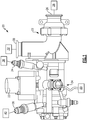
- Figure 1 shows an exemplary fueldraulic air valve assembly 20 for a gas turbine engine.
- the valve assembly 20 may be mounted on an engine or airframe.
- the engine may be a gas turbine engine, for example.
- Gas turbine engines are known, and may generally include a fan section, a compressor section, a combustor section and a turbine section, among other components.
- the gas turbine engine may be a two-spool turbofan gas turbine engine, a three-spool architecture, a direct drive turbofan, an industrial gas turbine (IGT), or any gas turbine engine as desired.
- IGT industrial gas turbine
- present application is not limited to use in conjunction with a gas turbine engine.
- present application is, for convenience of explanation, depicted and described as being implemented in a gas turbine engine, the present disclosure may be utilized in numerous other machines having air management assemblies.
- the example valve assembly 20 is configured to meter a high temperature fluid, such as bleed air.
- the valve assembly 20 generally includes an air valve 22 and an actuator 24.
- the high temperature fluid flows into a valve inlet 26 of the air valve 22 from a source 28, and exits a valve outlet 30 to a destination 32.
- the source 28 is bleed air from a compressor stage.
- the source 28 is high pressure and temperature air from the sixth stage of the high pressure compressor.
- the air flowing into the valve 22 may have temperatures greater than about 1000 °F (537.8 °C). In some embodiments, the air flowing into the valve 22 may have temperatures greater than about 1100 °F (593.3 °C).
- the actuator 24 is a fuel driven hydraulic actuator, known as a "fueldraulic" actuator. That is, the actuator 24 uses fuel as the working fluid. Fuel enters the actuator 24 through a port 34 and exits the actuator 24 through a port 36. In one example, fuel is communicated to the actuator 24 from a fuel source 38 and then provided to the fuel return 40 for use. In some examples, a position feedback, such as a linear variable displacement transformer (LVDT) 76 (shown in Figure 3 ) is in communication with the electronic controller 80, to control an electrohydraulic servo valve (EHSV) 23, to control the actuator 24 and valve 22.
- LVDT linear variable displacement transformer
- EHSV electrohydraulic servo valve
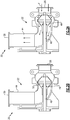
- FIG 2A illustrates a cross-sectional view of the air valve 22 in an open position.
- the air valve 22 may be a poppet valve, for example.
- a flow of fluid F flows through the valve along a flow path defined by a housing 44 from the inlet 26 to the outlet 30.
- a poppet 46 is arranged within arranged within the housing 44. In the open position, there is space about the poppet 46 for the fluid F to flow past.
- the poppet 46 is arranged on a shaft 48.
- the shaft 48 is attached to the actuator 24 (shown in Figures 1 and 3 ).
- Figure 2B illustrates a cross-sectional view of the air valve 22 in a closed position. In this position, fluid F does not flow through the valve 22.
- the poppet 46 abuts a seating surface 50.
- the poppet 46 contacts the seating surface 50 circumferentially about the shaft 48 such that no fluid F flows past the poppet 46. In other embodiments, a small amount of fluid F may flow past the poppet 46 in the closed position.
- the valve components such as the housing 44, poppet 46, and shaft 48 are formed from a material that can withstand very high heats because the fluid F may have temperatures over about 1000 °F (537.8 °C).
- the housing 44, poppet 46, and shaft 48 are formed a metallic material.
- the housing 44, poppet 46, and shaft 48 may be formed from a nickel alloy such as Inconel, for example.
- the housing 44, poppet 46, and shaft 48 may be the same material, or may be different materials.
- the valve 22 may be manipulated to various positions between the open and closed positions. This may permit modulation of the air flow.
- the valve 22 may be moved to an infinite number of positions between the open and closed positions, for example.
- the position of the valve 22 is controlled by the actuator 24 via the shaft 48.
- the actuator 24 may be controlled by an EHSV 23 (shown in Figure 1 ), for example.
- the actuator 24 and the EHSV 23 may have an upper temperature limit that is much lower than the temperature of the fluid F.
- the actuator 24 and EHSV 23 may have an upper temperature limit of about 300 °F (148.9 °C).
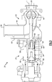
- FIG. 3 illustrates a cross-sectional view of the valve assembly 20.
- the valve housing 44 is mechanically attached to an actuator housing 58.
- a thermal barrier 60 may be arranged between the valve housing 44 and the actuator housing 58.
- the thermal barrier 60 helps to mitigate heat transfer from the valve housing 44 to the actuator housing 58.
- a radiant barrier 62 may also be arranged between the valve housing 44 and the actuator housing 58. The radiant barrier 62 provides a shield between the housings 44, 58 to mitigate heat transfer.
- the shaft 48 extends through the valve housing 44 into the actuator housing 58.
- the shaft 48 may have a threaded portion 52 that is secured to an end portion 55 of a piston rod 54.
- the piston rod 54 is actuated by the fuel in the actuator 24, which in turn actuates the shaft 48 and poppet 46.
- a thermal barrier 56 may be arranged between the shaft 48 and the piston rod 54. The thermal barrier 56 helps mitigate heat transfer from the shaft 48 to the piston rod 54, and thus the fuel.
- a cavity 64 is defined within the actuator housing 58.
- the cavity 64 may surround a portion of the shaft 48.
- the cavity 64 surrounds the threaded portion 52 where the shaft 48 is coupled to the piston rod 54.
- a cooling port 66 may extend through the actuator housing 58 into the cavity 64.
- Ambient air may flow through the cooling port 66 into the cavity 64 to help cool the shaft 48.
- the ambient air may be air located within an engine nacelle compartment, for example. Generally, the ambient air surrounding the assembly 20 is cooler than the fluid F flowing through the valve 22.
- another cooling port 68 is arranged within the threaded portion 52 of the shaft 48 to help cool the shaft 48. The cooling port 68 permits ambient air to flow into a cavity defined within the shaft 48.
- Cooling fins 72 may be arranged on the piston rod 54 or the shaft 48.
- the cooling fins 72 help dissipate heat transfer between the shaft 48, and the ambient air.
- the cooling fins 72 may be machined onto the shaft 48, for example.
- a locking insert 70 may be arranged between the shaft 48 and the actuator piston rod 54.
- the locking insert 70 helps resist twisting of the shafts 48, 54 relative to one another.
- the locking insert 70 may also provide an additional thermal barrier between the shaft 48 and piston rod 54.
- Seals 74 may be arranged about the piston rod 54.
- the seals 74 help prevent fuel from travelling down the piston rod 54.
- the flowing fuel from the fuel source 38 to the fuel return 40 may be ported around the seals 74 to provide internal cooling via a port 90.
- the port 90 may include drilled lines, for example.
- the fuel actuator 24 may be controlled actively.
- an LVDT 76 provides information regarding the linear position of the actuator 24.
- the LVDT may communicate with the electroninc controller 80, for example.
- the thermal barriers 60, 56 may be formed from materials that have a low heat transfer coefficient.
- the barriers 60, 56 may be formed from ceramic or titanium. Other materials having a low heat transfer coefficient may be used, however. In some examples, a material having moderate compressive strength, such as titanium, may be helpful.
- a sandwiched material may be useful for the barriers 60, 56, in some examples. For example, a material with layers including a thermal paper may be used to help prevent heat transfer.
- the interfacing surfaces may have a finish to prevent heat transfer.
- surfaces of the housings 58, 44, or thermal barriers 56, 60 may be machined to increase roughness of the mating surfaces. This is to minimize surface contact between the mating surfaces, lowering the amount of heat transfer between the mating surfaces.
- the disclosed assembly permits the air valve to be coupled to a fuel actuator.
- the air valve receives air at a very high temperature, while the fuel actuator must remain at a relatively low temperature.
- the thermal barriers and cooling features help minimize heat transfer from the high temperature air to the fuel actuator.
- Thermal barriers may be arranged between the shafts 48, 54, and/or between the housings 44, 58 to mitigate heat transfer.
- the disclosed features may help minimize conductive, convective, and radiative heat transfer.
- the fueldraulic actuator may provide better modulation of the air valve and be more reliable than known air valve actuators.
Landscapes
- Engineering & Computer Science (AREA)
- General Engineering & Computer Science (AREA)
- Chemical & Material Sciences (AREA)
- Combustion & Propulsion (AREA)
- Mechanical Engineering (AREA)
- Physics & Mathematics (AREA)
- Fluid Mechanics (AREA)
- Life Sciences & Earth Sciences (AREA)
- Sustainable Development (AREA)
- Temperature-Responsive Valves (AREA)
- Fluid-Driven Valves (AREA)
- Details Of Valves (AREA)
Abstract
Description
- This disclosure relates to an air valve system and more particularly a fueldraulic air valve system.
- A gas turbine engine typically includes a fan section, a compressor section, a combustor section, and a turbine section. Air moves into the engine through the fan section. Airfoil arrays in the compressor section rotate to compress the air, which is then mixed with fuel and combusted in the combustor section. The products of combustion are expanded to rotatably drive airfoil arrays in the turbine section. Rotating the airfoil arrays in the turbine section drives rotation of the fan and compressor sections. The compressor section and turbine section each have multiple stages of blades that rotate about a central axis and multiple stages of vanes that are stationary relative to the central axis.
- Some gas turbine engines have air valves for bleed air. Bleed air may be used in the engine such as for starting, low power stability, and stall recovery, for example.
- In one exemplary embodiment, a valve assembly for a turbine engine includes a valve arranged in an air flow path. The valve has a shaft. The valve is movable between an open position and a closed position. A hydraulic actuator is coupled to the shaft. The hydraulic actuator is configured to utilize fuel as a working fluid. The hydraulic actuator is configured to move the valve between the open position and the closed position.
- In a further embodiment of any of the above, the valve is a poppet valve.
- In a further embodiment of any of the above, the air flow path is configured to have a temperature of greater than about 1000°F (537.8 °C).
- In a further embodiment of any of the above, the hydraulic actuator is configured to move the valve to an infinite number of positions between the open position and the closed position.
- In a further embodiment of any of the above, the valve is formed from metallic components.
- In a further embodiment of any of the above, a thermal barrier is arranged between the valve and the hydraulic actuator.
- In a further embodiment of any of the above, cooling fins are arranged on the shaft.
- In a further embodiment of any of the above, a linear variable displacement transformer is arranged on the shaft.
- In a further embodiment of any of the above, the shaft comprises a first shaft portion that is attached to the valve and a second shaft portion attached to the actuator. A thermal barrier is arranged between the first and second shaft portions.
- In a further embodiment of any of the above, an actuator housing defines a cavity about the shaft. A cooling port extends through the housing to permit ambient air to flow into the cavity.
- In a further embodiment of any of the above, a second cavity is defined within the shaft. A second cooling port extends through the shaft to permit ambient air to flow into the second cavity.
- In a further embodiment of any of the above, a plurality of seals are arranged between the hydraulic actuator and the valve.
- In a further embodiment of any of the above, the actuator housing includes a port configured to communicate fuel around the plurality of seals.
- In another exemplary embodiment, a turbine engine includes a compressor configured to deliver air to a combustor. A valve assembly has a valve arranged in an air flow path. The valve has a shaft. The valve is movable between an open position and a closed position. A hydraulic actuator is coupled to the shaft. The hydraulic actuator is configured to utilize fuel as a working fluid. The hydraulic actuator is configured to move the valve between the open position and the closed position.
- In a further embodiment of any of the above, the air flow path receives bleed air from the compressor.
- In a further embodiment of any of the above, the fuel is delivered to the fuel return downstream of the hydraulic actuator.
- In a further embodiment of any of the above, a thermal barrier is arranged between the valve and the hydraulic actuator.
- In a further embodiment of any of the above, the shaft comprises a first shaft portion that is attached to the valve and a second shaft portion attached to the actuator. A thermal barrier is arranged between the first and second shaft portions.
- In a further embodiment of any of the above the hydraulic actuator is configured to move the valve to an infinite number of positions between the open position and the closed position.
- In a further embodiment of any of the above an actuator housing defines a cavity about the shaft. A cooling port extends through the housing to permit ambient air to flow into the cavity.
- The disclosure can be further understood by reference to the following detailed description when considered in connection with the accompanying drawings.
-
Figure 1 is a schematic view of an example air valve assembly. -
Figure 2A is a cross-sectional view of a portion of the example air valve assembly in an open position. -
Figure 2B is a cross-sectional view of a portion of the example air valve assembly in a closed position. -
Figure 3 is a cross-sectional view of the example air valve assembly. -
Figure 1 shows an exemplary fueldraulicair valve assembly 20 for a gas turbine engine. Thevalve assembly 20 may be mounted on an engine or airframe. The engine may be a gas turbine engine, for example. Gas turbine engines are known, and may generally include a fan section, a compressor section, a combustor section and a turbine section, among other components. The gas turbine engine may be a two-spool turbofan gas turbine engine, a three-spool architecture, a direct drive turbofan, an industrial gas turbine (IGT), or any gas turbine engine as desired. - It should be appreciated that the present application is not limited to use in conjunction with a gas turbine engine. Thus, although the present application is, for convenience of explanation, depicted and described as being implemented in a gas turbine engine, the present disclosure may be utilized in numerous other machines having air management assemblies.
- The
example valve assembly 20 is configured to meter a high temperature fluid, such as bleed air. Thevalve assembly 20 generally includes anair valve 22 and anactuator 24. The high temperature fluid flows into avalve inlet 26 of theair valve 22 from asource 28, and exits avalve outlet 30 to adestination 32. In one example, thesource 28 is bleed air from a compressor stage. In a further example, thesource 28 is high pressure and temperature air from the sixth stage of the high pressure compressor. The air flowing into thevalve 22 may have temperatures greater than about 1000 °F (537.8 °C). In some embodiments, the air flowing into thevalve 22 may have temperatures greater than about 1100 °F (593.3 °C). - The
actuator 24 is a fuel driven hydraulic actuator, known as a "fueldraulic" actuator. That is, theactuator 24 uses fuel as the working fluid. Fuel enters theactuator 24 through aport 34 and exits theactuator 24 through aport 36. In one example, fuel is communicated to the actuator 24 from afuel source 38 and then provided to thefuel return 40 for use. In some examples, a position feedback, such as a linear variable displacement transformer (LVDT) 76 (shown inFigure 3 ) is in communication with theelectronic controller 80, to control an electrohydraulic servo valve (EHSV) 23, to control theactuator 24 andvalve 22. -
Figure 2A illustrates a cross-sectional view of theair valve 22 in an open position. Theair valve 22 may be a poppet valve, for example. A flow of fluid F flows through the valve along a flow path defined by ahousing 44 from theinlet 26 to theoutlet 30. Apoppet 46 is arranged within arranged within thehousing 44. In the open position, there is space about thepoppet 46 for the fluid F to flow past. Thepoppet 46 is arranged on ashaft 48. Theshaft 48 is attached to the actuator 24 (shown inFigures 1 and3 ). -
Figure 2B illustrates a cross-sectional view of theair valve 22 in a closed position. In this position, fluid F does not flow through thevalve 22. Thepoppet 46 abuts aseating surface 50. In one embodiment, thepoppet 46 contacts theseating surface 50 circumferentially about theshaft 48 such that no fluid F flows past thepoppet 46. In other embodiments, a small amount of fluid F may flow past thepoppet 46 in the closed position. - The valve components, such as the
housing 44,poppet 46, andshaft 48 are formed from a material that can withstand very high heats because the fluid F may have temperatures over about 1000 °F (537.8 °C). In some examples, thehousing 44,poppet 46, andshaft 48 are formed a metallic material. Thehousing 44,poppet 46, andshaft 48 may be formed from a nickel alloy such as Inconel, for example. Thehousing 44,poppet 46, andshaft 48 may be the same material, or may be different materials. - In some examples, the
valve 22 may be manipulated to various positions between the open and closed positions. This may permit modulation of the air flow. Thevalve 22 may be moved to an infinite number of positions between the open and closed positions, for example. The position of thevalve 22 is controlled by theactuator 24 via theshaft 48. Theactuator 24 may be controlled by an EHSV 23 (shown inFigure 1 ), for example. Theactuator 24 and theEHSV 23 may have an upper temperature limit that is much lower than the temperature of the fluid F. For example, theactuator 24 andEHSV 23 may have an upper temperature limit of about 300 °F (148.9 °C). -
Figure 3 illustrates a cross-sectional view of thevalve assembly 20. Thevalve housing 44 is mechanically attached to anactuator housing 58. Athermal barrier 60 may be arranged between thevalve housing 44 and theactuator housing 58. Thethermal barrier 60 helps to mitigate heat transfer from thevalve housing 44 to theactuator housing 58. In some embodiments, aradiant barrier 62 may also be arranged between thevalve housing 44 and theactuator housing 58. Theradiant barrier 62 provides a shield between thehousings - The
shaft 48 extends through thevalve housing 44 into theactuator housing 58. Theshaft 48 may have a threadedportion 52 that is secured to anend portion 55 of apiston rod 54. Thepiston rod 54 is actuated by the fuel in theactuator 24, which in turn actuates theshaft 48 andpoppet 46. Athermal barrier 56 may be arranged between theshaft 48 and thepiston rod 54. Thethermal barrier 56 helps mitigate heat transfer from theshaft 48 to thepiston rod 54, and thus the fuel. - In some examples, a
cavity 64 is defined within theactuator housing 58. Thecavity 64 may surround a portion of theshaft 48. In one example, thecavity 64 surrounds the threadedportion 52 where theshaft 48 is coupled to thepiston rod 54. A coolingport 66 may extend through theactuator housing 58 into thecavity 64. Ambient air may flow through the coolingport 66 into thecavity 64 to help cool theshaft 48. The ambient air may be air located within an engine nacelle compartment, for example. Generally, the ambient air surrounding theassembly 20 is cooler than the fluid F flowing through thevalve 22. In some examples, another coolingport 68 is arranged within the threadedportion 52 of theshaft 48 to help cool theshaft 48. The coolingport 68 permits ambient air to flow into a cavity defined within theshaft 48. - Cooling
fins 72 may be arranged on thepiston rod 54 or theshaft 48. The coolingfins 72 help dissipate heat transfer between theshaft 48, and the ambient air. The coolingfins 72 may be machined onto theshaft 48, for example. - A locking
insert 70 may be arranged between theshaft 48 and theactuator piston rod 54. The lockinginsert 70 helps resist twisting of theshafts insert 70 may also provide an additional thermal barrier between theshaft 48 andpiston rod 54. -
Seals 74 may be arranged about thepiston rod 54. Theseals 74 help prevent fuel from travelling down thepiston rod 54. The flowing fuel from thefuel source 38 to thefuel return 40, may be ported around theseals 74 to provide internal cooling via aport 90. Theport 90 may include drilled lines, for example. - The
fuel actuator 24 may be controlled actively. In some examples, anLVDT 76 provides information regarding the linear position of theactuator 24. The LVDT may communicate with theelectroninc controller 80, for example. - The
thermal barriers barriers barriers - In further embodiments, the interfacing surfaces may have a finish to prevent heat transfer. For example, surfaces of the
housings thermal barriers - The disclosed assembly permits the air valve to be coupled to a fuel actuator. The air valve receives air at a very high temperature, while the fuel actuator must remain at a relatively low temperature. The thermal barriers and cooling features help minimize heat transfer from the high temperature air to the fuel actuator. Thermal barriers may be arranged between the
shafts housings - The foregoing description shall be interpreted as illustrative and not in any limiting sense. A worker of ordinary skill in the art would understand that certain modifications could come within the scope of this disclosure. For these reasons, the following claims should be studied to determine the true scope and content of this disclosure.
Claims (15)
- A valve assembly (20) for a turbine engine, comprising:a valve (22) arranged in an air flow path, the valve having a shaft (48), the valve (22) movable between an open position and a closed position; anda hydraulic actuator (24) coupled to the shaft, the hydraulic actuator configured to utilize fuel as a working fluid, the hydraulic actuator (24) configured to move the valve (22) between the open position and the closed position.
- The valve assembly of claim 1, wherein the valve (22) is a poppet valve.
- The valve assembly of any preceding claim, wherein the air flow path is configured to have a temperature of greater than about 1000°F (537.8 °C).
- The valve assembly of any preceding claim, wherein the hydraulic actuator (24) is configured to move the valve (22) to an infinite number of positions between the open position and the closed position.
- The valve assembly of any preceding claim, wherein the valve (22) is formed from metallic components.
- The valve assembly of any preceding claim, wherein a thermal barrier is arranged between the valve (22) and the hydraulic actuator (24).
- The valve assembly of any preceding claim, wherein cooling fins are arranged on the shaft (48).
- The valve assembly of any preceding claim, wherein a linear variable displacement transformer is arranged on the shaft (48).
- The valve assembly of any preceding claim, wherein the shaft (48) comprises a first shaft portion that is attached to the valve (22) and a second shaft portion attached to the actuator (24), wherein a thermal barrier is arranged between the first and second shaft portions.
- The valve assembly of any preceding claim, wherein an actuator housing (58) defines a cavity about the shaft (48) and a cooling port (66) extends through the housing (58) to permit ambient air to flow into the cavity.
- The valve assembly of claim 10, wherein a second cavity is defined within the shaft (48) and a second cooling port extends through the shaft (48) to permit ambient air to flow into the second cavity.
- The valve assembly of any preceding claim, wherein a plurality of seals are arranged between the hydraulic actuator (24) and the valve (22).
- The valve assembly of claim 12, wherein the actuator housing (58) includes a port configured to communicate fuel around the plurality of seals.
- A turbine engine, comprising:a compressor configured to deliver air to a combustor; andthe valve assembly of any preceding claim.
- The turbine engine of claim 14, wherein the air flow path receives bleed air from the compressor, and preferably
wherein the fuel is delivered to the fuel return downstream of the hydraulic actuator.
Applications Claiming Priority (1)
| Application Number | Priority Date | Filing Date | Title |
|---|---|---|---|
| US16/421,959 US11448139B2 (en) | 2019-05-24 | 2019-05-24 | Fueldraulic air valve |
Publications (1)
| Publication Number | Publication Date |
|---|---|
| EP3741999A1 true EP3741999A1 (en) | 2020-11-25 |
Family
ID=68609994
Family Applications (1)
| Application Number | Title | Priority Date | Filing Date |
|---|---|---|---|
| EP19209737.6A Pending EP3741999A1 (en) | 2019-05-24 | 2019-11-18 | Fueldraulic air valve |
Country Status (2)
| Country | Link |
|---|---|
| US (1) | US11448139B2 (en) |
| EP (1) | EP3741999A1 (en) |
Families Citing this family (1)
| Publication number | Priority date | Publication date | Assignee | Title |
|---|---|---|---|---|
| GB202219409D0 (en) * | 2022-12-21 | 2023-02-01 | Rolls Royce Plc | Fuel management system |
Citations (4)
| Publication number | Priority date | Publication date | Assignee | Title |
|---|---|---|---|---|
| US20070102049A1 (en) * | 2005-11-09 | 2007-05-10 | Honeywell International, Inc. | Valve actuator assembly |
| US7540144B2 (en) * | 2005-10-21 | 2009-06-02 | Pratt & Whitney Canada Corp. | Bleed valve for a gas turbine engine |
| US20120167589A1 (en) * | 2010-12-30 | 2012-07-05 | Theodore Joseph Fritsch | Gas turbine engine and system for modulating secondary air flow |
| US20170335775A1 (en) * | 2016-05-17 | 2017-11-23 | Hamilton Sundstrand Corporation | Solenoids for gas turbine engine bleed valves |
Family Cites Families (9)
| Publication number | Priority date | Publication date | Assignee | Title |
|---|---|---|---|---|
| US5048286A (en) * | 1990-06-29 | 1991-09-17 | General Electric Company | Bypass valve door |
| US5988589A (en) * | 1996-07-17 | 1999-11-23 | Mowill; R. Jan | Air valve assembly including split-shaft and seal arrangement |
| US6742539B2 (en) * | 2000-05-24 | 2004-06-01 | Innovative Controls | Co-axial control valve |
| US6783108B2 (en) | 2001-08-17 | 2004-08-31 | Jansen's Aircraft Systems Controls, Inc. | Fueldraulic pintle valve |
| US6622472B2 (en) * | 2001-10-17 | 2003-09-23 | Gateway Space Transport, Inc. | Apparatus and method for thrust vector control |
| US20120045317A1 (en) * | 2010-08-23 | 2012-02-23 | Honeywell International Inc. | Fuel actuated bleed air system |
| US10100729B2 (en) * | 2015-01-19 | 2018-10-16 | Hamilton Sundstrand Corporation | Cooling device for electro-pneumatic controller |
| US10738791B2 (en) * | 2015-12-16 | 2020-08-11 | General Electric Company | Active high pressure compressor clearance control |
| GB201610312D0 (en) * | 2016-06-14 | 2016-07-27 | Rolls-Royce Controls And Data Services Ltd | Compressor geometry control |
-
2019
- 2019-05-24 US US16/421,959 patent/US11448139B2/en active Active
- 2019-11-18 EP EP19209737.6A patent/EP3741999A1/en active Pending
Patent Citations (4)
| Publication number | Priority date | Publication date | Assignee | Title |
|---|---|---|---|---|
| US7540144B2 (en) * | 2005-10-21 | 2009-06-02 | Pratt & Whitney Canada Corp. | Bleed valve for a gas turbine engine |
| US20070102049A1 (en) * | 2005-11-09 | 2007-05-10 | Honeywell International, Inc. | Valve actuator assembly |
| US20120167589A1 (en) * | 2010-12-30 | 2012-07-05 | Theodore Joseph Fritsch | Gas turbine engine and system for modulating secondary air flow |
| US20170335775A1 (en) * | 2016-05-17 | 2017-11-23 | Hamilton Sundstrand Corporation | Solenoids for gas turbine engine bleed valves |
Also Published As
| Publication number | Publication date |
|---|---|
| US20200370480A1 (en) | 2020-11-26 |
| US11448139B2 (en) | 2022-09-20 |
Similar Documents
| Publication | Publication Date | Title |
|---|---|---|
| US11035250B2 (en) | Gas turbine engine fluid cooling systems and methods of assembling the same | |
| EP2905425B1 (en) | Variable vane and seal arrangement | |
| US7946806B2 (en) | Gas turbine engine systems and related methods involving heat exchange | |
| US8448446B2 (en) | Actuating device, bypass air bleed system equipped therewith, and turbojet engine comprising these | |
| US9926801B2 (en) | Blade track assembly with turbine tip clearance control | |
| US10001066B2 (en) | Rotary actuator for variable geometry vanes | |
| US8066474B1 (en) | Variable guide vane actuator | |
| US11859500B2 (en) | Gas turbine engine with a fluid conduit system and a method of operating the same | |
| EP3133297B1 (en) | Gas turbine engine with actuator control | |
| US11788425B2 (en) | Gas turbine engine with clearance control system | |
| EP3163053A1 (en) | Bleed valve arrangement for a gas turbine engine | |
| EP3636971A1 (en) | A valve assembly | |
| EP3187699B1 (en) | Auto thermal valve (atv) for dual mode passive cooling flow modulation | |
| EP2554798A2 (en) | Rotor blade tip clearance control device and method | |
| CN103388493B (en) | Turbine and the clearance control system for turbine | |
| EP3636896B1 (en) | A controller assembly | |
| US11448139B2 (en) | Fueldraulic air valve | |
| EP3751149B1 (en) | Linear electric air valve | |
| US12305516B2 (en) | Gas turbine engine with a fluid conduit system and a method of operating the same | |
| EP4234891B1 (en) | Rotary servo for fixed fail actuators |
Legal Events
| Date | Code | Title | Description |
|---|---|---|---|
| PUAI | Public reference made under article 153(3) epc to a published international application that has entered the european phase |
Free format text: ORIGINAL CODE: 0009012 |
|
| STAA | Information on the status of an ep patent application or granted ep patent |
Free format text: STATUS: THE APPLICATION HAS BEEN PUBLISHED |
|
| AK | Designated contracting states |
Kind code of ref document: A1 Designated state(s): AL AT BE BG CH CY CZ DE DK EE ES FI FR GB GR HR HU IE IS IT LI LT LU LV MC MK MT NL NO PL PT RO RS SE SI SK SM TR |
|
| AX | Request for extension of the european patent |
Extension state: BA ME |
|
| STAA | Information on the status of an ep patent application or granted ep patent |
Free format text: STATUS: REQUEST FOR EXAMINATION WAS MADE |
|
| 17P | Request for examination filed |
Effective date: 20210517 |
|
| RBV | Designated contracting states (corrected) |
Designated state(s): AL AT BE BG CH CY CZ DE DK EE ES FI FR GB GR HR HU IE IS IT LI LT LU LV MC MK MT NL NO PL PT RO RS SE SI SK SM TR |
|
| STAA | Information on the status of an ep patent application or granted ep patent |
Free format text: STATUS: EXAMINATION IS IN PROGRESS |
|
| 17Q | First examination report despatched |
Effective date: 20220412 |