EP3741939A1 - Latch and catch assembly - Google Patents
Latch and catch assembly Download PDFInfo
- Publication number
- EP3741939A1 EP3741939A1 EP19215966.3A EP19215966A EP3741939A1 EP 3741939 A1 EP3741939 A1 EP 3741939A1 EP 19215966 A EP19215966 A EP 19215966A EP 3741939 A1 EP3741939 A1 EP 3741939A1
- Authority
- EP
- European Patent Office
- Prior art keywords
- hooks
- catch
- gear rail
- latch
- latch mechanism
- Prior art date
- Legal status (The legal status is an assumption and is not a legal conclusion. Google has not performed a legal analysis and makes no representation as to the accuracy of the status listed.)
- Granted
Links
Images




Classifications
-
- E—FIXED CONSTRUCTIONS
- E05—LOCKS; KEYS; WINDOW OR DOOR FITTINGS; SAFES
- E05C—BOLTS OR FASTENING DEVICES FOR WINGS, SPECIALLY FOR DOORS OR WINDOWS
- E05C19/00—Other devices specially designed for securing wings, e.g. with suction cups
- E05C19/10—Hook fastenings; Fastenings in which a link engages a fixed hook-like member
- E05C19/12—Hook fastenings; Fastenings in which a link engages a fixed hook-like member pivotally mounted around an axis
-
- E—FIXED CONSTRUCTIONS
- E05—LOCKS; KEYS; WINDOW OR DOOR FITTINGS; SAFES
- E05B—LOCKS; ACCESSORIES THEREFOR; HANDCUFFS
- E05B65/00—Locks or fastenings for special use
- E05B65/52—Other locks for chests, boxes, trunks, baskets, travelling bags, or the like
-
- E—FIXED CONSTRUCTIONS
- E05—LOCKS; KEYS; WINDOW OR DOOR FITTINGS; SAFES
- E05C—BOLTS OR FASTENING DEVICES FOR WINGS, SPECIALLY FOR DOORS OR WINDOWS
- E05C3/00—Fastening devices with bolts moving pivotally or rotatively
- E05C3/12—Fastening devices with bolts moving pivotally or rotatively with latching action
- E05C3/16—Fastening devices with bolts moving pivotally or rotatively with latching action with operating handle or equivalent member moving otherwise than rigidly with the latch
- E05C3/22—Fastening devices with bolts moving pivotally or rotatively with latching action with operating handle or equivalent member moving otherwise than rigidly with the latch the bolt being spring controlled
- E05C3/30—Fastening devices with bolts moving pivotally or rotatively with latching action with operating handle or equivalent member moving otherwise than rigidly with the latch the bolt being spring controlled in the form of a hook
- E05C3/34—Fastening devices with bolts moving pivotally or rotatively with latching action with operating handle or equivalent member moving otherwise than rigidly with the latch the bolt being spring controlled in the form of a hook with simultaneously operating double bolts
-
- E—FIXED CONSTRUCTIONS
- E05—LOCKS; KEYS; WINDOW OR DOOR FITTINGS; SAFES
- E05B—LOCKS; ACCESSORIES THEREFOR; HANDCUFFS
- E05B5/00—Handles completely let into the surface of the wing
- E05B5/006—Handles completely let into the surface of the wing essentially defining a completely closed surface together with the wing
-
- E—FIXED CONSTRUCTIONS
- E05—LOCKS; KEYS; WINDOW OR DOOR FITTINGS; SAFES
- E05C—BOLTS OR FASTENING DEVICES FOR WINGS, SPECIALLY FOR DOORS OR WINDOWS
- E05C19/00—Other devices specially designed for securing wings, e.g. with suction cups
-
- B—PERFORMING OPERATIONS; TRANSPORTING
- B64—AIRCRAFT; AVIATION; COSMONAUTICS
- B64D—EQUIPMENT FOR FITTING IN OR TO AIRCRAFT; FLIGHT SUITS; PARACHUTES; ARRANGEMENT OR MOUNTING OF POWER PLANTS OR PROPULSION TRANSMISSIONS IN AIRCRAFT
- B64D11/00—Passenger or crew accommodation; Flight-deck installations not otherwise provided for
- B64D11/003—Stowage devices for passengers' personal luggage
-
- E—FIXED CONSTRUCTIONS
- E05—LOCKS; KEYS; WINDOW OR DOOR FITTINGS; SAFES
- E05C—BOLTS OR FASTENING DEVICES FOR WINGS, SPECIALLY FOR DOORS OR WINDOWS
- E05C5/00—Fastening devices with bolts moving otherwise than only rectilinearly and only pivotally or rotatively
-
- E—FIXED CONSTRUCTIONS
- E05—LOCKS; KEYS; WINDOW OR DOOR FITTINGS; SAFES
- E05C—BOLTS OR FASTENING DEVICES FOR WINGS, SPECIALLY FOR DOORS OR WINDOWS
- E05C9/00—Arrangements of simultaneously actuated bolts or other securing devices at well-separated positions on the same wing
- E05C9/04—Arrangements of simultaneously actuated bolts or other securing devices at well-separated positions on the same wing with two sliding bars moved in opposite directions when fastening or unfastening
- E05C9/041—Arrangements of simultaneously actuated bolts or other securing devices at well-separated positions on the same wing with two sliding bars moved in opposite directions when fastening or unfastening with rack and pinion mechanism
-
- Y—GENERAL TAGGING OF NEW TECHNOLOGICAL DEVELOPMENTS; GENERAL TAGGING OF CROSS-SECTIONAL TECHNOLOGIES SPANNING OVER SEVERAL SECTIONS OF THE IPC; TECHNICAL SUBJECTS COVERED BY FORMER USPC CROSS-REFERENCE ART COLLECTIONS [XRACs] AND DIGESTS
- Y10—TECHNICAL SUBJECTS COVERED BY FORMER USPC
- Y10T—TECHNICAL SUBJECTS COVERED BY FORMER US CLASSIFICATION
- Y10T292/00—Closure fasteners
- Y10T292/08—Bolts
- Y10T292/0801—Multiple
- Y10T292/0803—Sliding and swinging
- Y10T292/0805—Combined motion
-
- Y—GENERAL TAGGING OF NEW TECHNOLOGICAL DEVELOPMENTS; GENERAL TAGGING OF CROSS-SECTIONAL TECHNOLOGIES SPANNING OVER SEVERAL SECTIONS OF THE IPC; TECHNICAL SUBJECTS COVERED BY FORMER USPC CROSS-REFERENCE ART COLLECTIONS [XRACs] AND DIGESTS
- Y10—TECHNICAL SUBJECTS COVERED BY FORMER USPC
- Y10T—TECHNICAL SUBJECTS COVERED BY FORMER US CLASSIFICATION
- Y10T292/00—Closure fasteners
- Y10T292/08—Bolts
- Y10T292/0801—Multiple
- Y10T292/0825—Hooked end
-
- Y—GENERAL TAGGING OF NEW TECHNOLOGICAL DEVELOPMENTS; GENERAL TAGGING OF CROSS-SECTIONAL TECHNOLOGIES SPANNING OVER SEVERAL SECTIONS OF THE IPC; TECHNICAL SUBJECTS COVERED BY FORMER USPC CROSS-REFERENCE ART COLLECTIONS [XRACs] AND DIGESTS
- Y10—TECHNICAL SUBJECTS COVERED BY FORMER USPC
- Y10T—TECHNICAL SUBJECTS COVERED BY FORMER US CLASSIFICATION
- Y10T292/00—Closure fasteners
- Y10T292/08—Bolts
- Y10T292/0801—Multiple
- Y10T292/0825—Hooked end
- Y10T292/0826—Operating means
- Y10T292/0828—Link and lever
-
- Y—GENERAL TAGGING OF NEW TECHNOLOGICAL DEVELOPMENTS; GENERAL TAGGING OF CROSS-SECTIONAL TECHNOLOGIES SPANNING OVER SEVERAL SECTIONS OF THE IPC; TECHNICAL SUBJECTS COVERED BY FORMER USPC CROSS-REFERENCE ART COLLECTIONS [XRACs] AND DIGESTS
- Y10—TECHNICAL SUBJECTS COVERED BY FORMER USPC
- Y10T—TECHNICAL SUBJECTS COVERED BY FORMER US CLASSIFICATION
- Y10T292/00—Closure fasteners
- Y10T292/08—Bolts
- Y10T292/0801—Multiple
- Y10T292/0848—Swinging
- Y10T292/0849—Operating means
- Y10T292/0856—Gear
-
- Y—GENERAL TAGGING OF NEW TECHNOLOGICAL DEVELOPMENTS; GENERAL TAGGING OF CROSS-SECTIONAL TECHNOLOGIES SPANNING OVER SEVERAL SECTIONS OF THE IPC; TECHNICAL SUBJECTS COVERED BY FORMER USPC CROSS-REFERENCE ART COLLECTIONS [XRACs] AND DIGESTS
- Y10—TECHNICAL SUBJECTS COVERED BY FORMER USPC
- Y10T—TECHNICAL SUBJECTS COVERED BY FORMER US CLASSIFICATION
- Y10T292/00—Closure fasteners
- Y10T292/08—Bolts
- Y10T292/0862—Swinging and hooked end, multiple head
-
- Y—GENERAL TAGGING OF NEW TECHNOLOGICAL DEVELOPMENTS; GENERAL TAGGING OF CROSS-SECTIONAL TECHNOLOGIES SPANNING OVER SEVERAL SECTIONS OF THE IPC; TECHNICAL SUBJECTS COVERED BY FORMER USPC CROSS-REFERENCE ART COLLECTIONS [XRACs] AND DIGESTS
- Y10—TECHNICAL SUBJECTS COVERED BY FORMER USPC
- Y10T—TECHNICAL SUBJECTS COVERED BY FORMER US CLASSIFICATION
- Y10T292/00—Closure fasteners
- Y10T292/08—Bolts
- Y10T292/0911—Hooked end
-
- Y—GENERAL TAGGING OF NEW TECHNOLOGICAL DEVELOPMENTS; GENERAL TAGGING OF CROSS-SECTIONAL TECHNOLOGIES SPANNING OVER SEVERAL SECTIONS OF THE IPC; TECHNICAL SUBJECTS COVERED BY FORMER USPC CROSS-REFERENCE ART COLLECTIONS [XRACs] AND DIGESTS
- Y10—TECHNICAL SUBJECTS COVERED BY FORMER USPC
- Y10T—TECHNICAL SUBJECTS COVERED BY FORMER US CLASSIFICATION
- Y10T292/00—Closure fasteners
- Y10T292/08—Bolts
- Y10T292/0911—Hooked end
- Y10T292/0921—Multiple head
-
- Y—GENERAL TAGGING OF NEW TECHNOLOGICAL DEVELOPMENTS; GENERAL TAGGING OF CROSS-SECTIONAL TECHNOLOGIES SPANNING OVER SEVERAL SECTIONS OF THE IPC; TECHNICAL SUBJECTS COVERED BY FORMER USPC CROSS-REFERENCE ART COLLECTIONS [XRACs] AND DIGESTS
- Y10—TECHNICAL SUBJECTS COVERED BY FORMER USPC
- Y10T—TECHNICAL SUBJECTS COVERED BY FORMER US CLASSIFICATION
- Y10T292/00—Closure fasteners
- Y10T292/42—Rigid engaging means
- Y10T292/438—Spring-arm catch
Definitions
- Storage bins, doors, cabinets and other stowage elements in vehicles such as aircraft require secure closure for safety purposes.
- Necessary equipment and passenger personal belongings are present on commercial airline flights, for example, and so storage areas are provided to both crew members and airline customers. Passengers are generally untrained as to the operation of cabin equipment. Accordingly, the equipment offered for passenger use should be conveniently and intuitively operable.
- closures should be secure to avoid both unintended opening and any rattling or other noise-producing vibrations that might contribute to any passenger perceptions of insecurity.
- Airline operators prefer smooth and uncluttered cabin elements for clean aesthetic purposes.
- the secure closure of doors and panels and other movable effects should be discernible by momentary inspection as flight attendants move through a passenger cabin for preflight inspections and preparations.
- the profiles of handles and levers that operate aircraft stowage equipment should be minimized to prevent such elements from jutting unnecessarily into aisles and seating areas.
- Overhead storage bins are of particular concern with regard both to secure closure and to minimizing the extension of handles and levers and such from stowage doors.
- Improvements are needed in latching mechanisms for automatically achieving the secure latching of stowage doors upon closure. Improvements are also needed in intuitively operable closure latches that are flush with cabin structures such as storage bin walls and doors.
- the present invention provides a latch and catch assembly including a catch attachable to a first structure and a latch mechanism attachable to a second structure, the latch mechanism and the catch cooperating to secure the first structure relative to the second structure.
- the latch mechanism includes first and second hooks mounted for pivoting movement between an engagement position for engaging with the catch and a disengagement position for disengaging from the catch, a translating gear rail positioned between the first and second hooks, the translating rail engaged on opposing lateral sides thereof with the respective first and second hooks, and an actuator mechanism operable for driving movement of the translating gear rail to drive simultaneous pivoting movement of the first and second hooks apartto drive ends of the first and second hooks apart toward their disengagement position.
- the driving movement of the translating gear rail to drive simultaneous pivoting movement of the first and second hooks may be in opposite directions.
- each of the first and second hooks are rotatably mounted on a shaft coupled to a base plate, and wherein each of the first and second hooks are rotationally-biased in a direction toward their engagement position by a torsion spring mounted on the shaft and engaging the respective one of the first and second hooks.
- the translating gear rail is movably positioned on the base plate between the first and second hooks and has longitudinally-spaced gear teeth formed on the opposing lateral sides thereof engaging gear teeth on mounting rings of the first and second hooks, the gear teeth of the translating gear rail engaging the gear teeth of the mounting rings such that linear movement of the translating gear rail is coordinated with pivoting movement of the first and second hooks.
- movement of the translating gear rail in a first direction drives pivoting movement of the first and second hooks toward their disengagement position
- movement of the translating gear assembly, or gear rail in a second direction opposite the first direction drives the first and second hooks toward their engagement position
- each of the first and second hooks includes a pivotally-attached end and a hooked end, and wherein the hooked ends are positioned spaced apart and facing each other when the first and second hooks are in their engagement position.
- the catch includes a strike plate, embodied herein as a mounting plate comprising a strike portion, positioned between first and second spaced openings, the translating gear rail adapted to contact the strike plate to move the translating gear rail away from the catch to drive the first and second hooks toward their engagement position, and the first and second hooks adapted to be received in the respective first and second openings to engage the first and second hooks with the catch in their engagement position.
- a strike plate embodied herein as a mounting plate comprising a strike portion, positioned between first and second spaced openings, the translating gear rail adapted to contact the strike plate to move the translating gear rail away from the catch to drive the first and second hooks toward their engagement position, and the first and second hooks adapted to be received in the respective first and second openings to engage the first and second hooks with the catch in their engagement position.
- the latch mechanism is mountable on an interior wall of a storage bin and the catch is mountable on a door pivotally attached to the storage bin, whereby, when the first and second hooks engage the catch in their engagement position, the door is latched in a closed condition.
- the latch mechanism further includes a base plate and keeper attached to the base plate, the keeper maintaining persistent contact with the translating gear rail by a spring force of a clip, and the translating gear rail having ridges on an outer face thereof within which the clip engages to maintain the first and second hooks in their disengagement position.
- the actuator mechanism includes a user-actuatable pin for moving the translating gear rail toward the catch, thereby pivoting the first and second hooks toward their disengagement position.
- the actuator mechanism includes an actuatable handle, wherein pivoting the handle causes the translating gear rail to move toward the catch.
- the present invention provides a cabinet assembly including a cabinet having a latch mechanism according to the first aspect wherein the second structure is embodied as a cabinet, wherein the first structure is embodied as a door pivotally-attached to the cabinet and wherein the latch mechanism comprises a base plate.
- the first and second hooks are mounted on shafts of the base plate and the translating gear rail is positioned to coordinate translating gear rail movement with pivoting movement of the first and second hooks.
- each of the first and second hooks includes a pivotally-attached end and a hooked end, and wherein the hooked ends are ramped such that engagement of the hooked ends with the catch deflects the first and second hooks toward their disengagement position.
- the actuator mechanism includes an actuatable handle, wherein pivoting the handle causes the translating gear rail to move toward the catch thereby pushing the catch away from the latch mechanism and opening the door.
- the present invention provides a latch and catch assembly including a catch attachable to a door, and a latch mechanism attachable to a structure to which the door is pivotally attached, the latch mechanism and the catch cooperating to secure the door in a closed condition, and the latch mechanism including first and second hooks mounted for pivoting movement between an engagement position for engaging with the catch and a disengagement position for disengaging from the catch, a translating gear rail positioned between the first and second hooks coordinating pivoting movement of the first and second hooks, and an actuator mechanism for driving movement of the translating gear rail to drive the first and second hooks toward their disengagement position.
- Embodiments of the present invention may include one or more or any combination of the above aspects, features and configurations.
- a storage door is automatically latched upon reaching a closed position by a latch mechanism having spring-loaded geared hooks that engage a door-mounted catch.
- a user can lift a handle or depress a button, depending on the actuator configuration, to disengage the hooks and open the door. Actuation of the handle or depressing the button ultimately rotates the spring-loaded hooks from their engaged positions permitting the catch to swing away from the latch mechanism by opening of the door.
- User actuation of the handle or button linearly extends a translating gear rail engaged with the geared hooks and, by forward linear movement of the gear rail, the hooks are rotated from their extended and engaged position to withdrawn and disengaged positions.
- a keeper maintains the gear rail in the extended position until the catch is returned to the latch mechanism by closure of the door. Upon closure, the catch presses the gear rail rearward from the extended position, overcoming the keeper, and automatically causing the hooks to re-engage the catch.
- FIG. 1 A non-limiting example of a latchable storage bin 20 is shown in FIG. 1 .
- the storage bin 20 may be fixed or mobile in a passenger or crew environment of a vehicle such as an aircraft.
- the storage bin 20 includes a main container 22 and a door 24 pivotally connected to the main container by a hinge 25.
- the storage bin 20 is illustrated as a box having a generally rectangular shape with planar walls and a rectangular planar hinged door 24 hinged at the top of the door.
- the storage bin 20 has an open or closed interior according to the position of the door 24 from the illustrated open position to a closed position at which the door 24 is brought in contact or at least closely proximal to the forward edges of the walls of the box.
- the main container 22 and door 24 can be of shaped to fit into spaces between other elements in an in-use environment.
- the storage container 22 can each be curved and contoured and can have tapered ends and edges.
- the inward side of the door 24 and the outward edges of the walls of the box are sufficiently matched to bring a latch mechanism 50, illustrated as mounted in a wall 26 of the box, into engagement with a catch 30, illustrated as carried by the door 24, into engagement as the door 24 is brought to the closed position.
- FIGS. 1-7 Two expressly illustrated embodiments of a latch mechanism 100 are shown in the drawings.
- the latch mechanism 50 in one embodiment can be disengaged from the catch 30 by use of a user-actuatable handle 52, permitting the door 24 to open.
- a latch mechanism in another embodiment can be disengaged from the catch 30 by use of a user-actuatable button.
- the latch mechanism 50 of the first illustrated embodiment includes a base plate 54 upon which two hooks are pivotally mounted.
- Two laterally spaced axles or shafts referenced as a first axle 56 and a second axle 58 ( FIG. 5 ), extend parallel to each other from a first side of the base plate 54.
- the hooks 60 and 62 referenced as the first hook 60 and second hook 62, are pivotally mounted on the first axle 56 and second axle 58 respectively.
- the hooks are retained on the axles, each by a washer and a retaining ring.
- Each hook has a mounting ring 64 received onto the respective axle.
- An arm 66 extends from a first side of the mounting ring 64 defined as the forward side when the hook is in the engagement position of FIG. 4 .
- Each arm 66 has a hook 68 at its terminal end opposite the mounting ring 64.
- a second side 70 ( FIG. 4 ) of each mounting ring 64 defined as the rearward side when the hook is in the engagement position of FIG. 4 , has gear teeth such that the mounting ring 64 defines at least a partially toothed spur gear at least along the second side 70 thereof.
- the hooks 60 and 62 are symmetrically formed and arranged such, when the hooks 60 and 62 are pivoted by partial rotation into their engagement positions, the arms 66 extend forward and parallel to each other and the hooks 68 extend laterally into the space between the arms 66. When the hooks 60 and 62 are pivoted by partial rotation into their disengagement positions ( FIG. 6 ), the arms 66 withdraw and extend laterally, in opposite lateral directions relative to each other, and the hooks 68 are directed forward.
- a gear rail 72 is movably positioned on the base plate 54 between the hooks 60 and 62, engaging the gear teeth along the second sides of the hooks 60 and 62.
- the gear rail 72 has a forward rail section 74 extending variably between the mounting rings 64 of the hooks 60 and 62 and a rearward rail section variably positioned relative to the base plate 54. At least the forward rail section 74, along two lateral sides thereof, has laterally extending and longitudinally spaced gear teeth.
- the gear teeth of the gear rail 72 engage the toothed mounting rings 64 of the hooks 60 and 62 such that forward linear movement of the gear rail 72 is coordinated with pivoting movement of the hooks 60 and 62 toward their disengagement positions ( FIG. 6 ).
- rearward linear movement of the gear rail 72 is coordinated with pivoting movement of the hooks 60 and 62 toward their engagement positions ( FIG. 4 ).
- the gear rail 72 is in a forward-most first position ( FIG. 6 )
- the hooks 60 and 62 are in their disengagement positions.
- the gear rail 72 is in a rearward-most second position ( FIG. 4 )
- the hooks 60 and 62 are in their engagement positions.
- a keeper 80 maintains the gear rail 72 on the base plate 54.
- the keeper 80 has a bridge 82 with lateral tabs by which the keeper is bolted to the base plate 54.
- a clip 84 extends longitudinally forward from the bridge.
- a contact tip at the forward terminal end of the clip 84 extends toward the gear rail 72 and maintains persistent contact with the gear rail 72 by a spring force of the clip 84.
- the contact tip is illustrated as curved bend at the forward end of the clip 84.
- the gear rail 72 has a rearward rail section 76 extending variably between the bridge and base plate 54, with the lateral tabs of the keeper 80 adjacent opposite lateral sides of the gear rail 72.
- the gear rail 72 has an outer face directed toward the keeper 80. Ridges 78 on the outer face register the gear rail 72 relative to the base plate 54 when the gear rail 72 reaches the forward position ( FIG. 6 ) by engaging the contact tip of the keeper 80.
- the keeper 80 retains the gear rail 72 in the forward position, and the hooks 60 and 62 in the disengagement positions, until sufficient force is applied to the gear rail 72 to overcome the engagement of the contact tip of the keeper 80 with the ridges 78 on the outer face of the gear rail 72.
- Each hook 60 and 62 is biased toward its engagement position ( FIG. 4 ) by a respective torsion spring.
- a first torsion spring 90 received onto the first axle 56 has opposing ends engaging the base plate 54 and first hook 60 respectively.
- a second torsion spring 92 received onto the second axle 58 has opposing ends engaging the base plate 54 and second hook 62 respectively.
- the torsion springs apply rotational force (torque) to the respective hooks, thereby rotationally biasing the hooks 60 and 62 to the engagement positions.
- each torsion spring (90,92) is mounted on a respective axle (56,58) and positioned between the mounting ring 64 of the corresponding hook and the base 54. As the first torsion spring 90 and second torsion spring 92 respectively bias the first hook 60 and second hook 62 toward the engagement positions, the gear rail 72 is biased toward the rearward-most second position of FIG. 4 .
- the user actuatable handle 52 is pivotally connected to a second side of the base plate 54, opposite the side on which the gear rail 72 is mounted.
- a lever 94 connected to the handle 52 pivots relative to the base plate 54 when the handle 52 is moved.
- a forward face of the lever 94 contacts the rearward end 77 of the gear rail 72.
- the handle 52 is pivotable relative to the base plate 54 from the position of FIGS. 2-5 to the position of FIGS. 6-7 .
- the position of FIGS. 6-7 is termed a first position of the handle 52, and the position of FIGS. 2-5 is termed a second position, in correspondence respectively with the forward-most first position ( FIG. 6 ) and the rearward-most second position ( FIG. 4 ) of the gear rail 72.
- the handle 52 is pivotally connected to the second side of the base plate 54 by way of a mounting cup 96 by which the latch mechanism 50 is mounted in the wall 26 of the storage bin 20 in FIG. 1 .
- a flange 98 along an edge of the cup 98 engages the wall 26, with the mounting cup 96 sunken into the wall.
- the latch mechanism 50 is fixed to the wall by engagement of the flange 98 with an exterior side of the wall, and engagement of the flange 98 with an interior side of the wall.
- Interior side and exterior side refer to the interior and exterior of the storage bin 20 respectively.
- the handle 52 is positioned in the cup 96 with the exterior side of the handle 52 being flush or smoothly aligned with the flange 98 and wall exterior.
- the handle 52 is pivoted outward from the cup 96.
- the cup 96 defines an area greater than an area of the handle 52.
- the cup 96 defines an opening 97 ( FIG. 2 ) in any position of the handle 52 to permit a user to pull the handle 52 from the second position to the first position to disengage the hooks 60 and 62 from the catch ( FIG. 3 ).
- the catch 30 includes a mounting plate 32 for attachment to any element to be engaged with the latch mechanism 50.
- the mounting plate 32 is attached to an edge of the door 24 in the storage bin 20 in FIG. 1 .
- the mounting plate 32 has a first opening 34 for the first hook 60 and a second opening 36, laterally spaced from the first opening, for receiving the second hook 62.
- the first opening 34 and second opening 36 are dimensioned and spaced to accommodate pivoting movements of first hook 60 and second hook 62 from their engagement positions ( FIG. 4 ) to their disengagement positions ( FIG. 6 ).
- a strike portion 38 of the mounting plate between the first opening and second opening serves to engage the catch 30 with the hooks 60 and 62.
- the catch 30 When the catch 30 is brought within the effective reach of the hooks 60 and 62, for example by closure of the door 24 with respect to the main container 22 ( FIG. 1 ), pivoting of the hooks 60 and 62 to their engagement positions ( FIG. 4 ) captures the strike portion 38 of the mounting plate 32 between the arms 66, with the arms 66 extending through the openings 34 and 36, and with the hooks 68 preventing separation of the catch 30 from the latch mechanism 50.
- the catch 30 includes a dished grip 40 extending from the mounting plate 32 for use in manipulating the door 24 by hand. The dished grip 40 is sunken into an edge of the door 24 in the example of FIG. 1 .
- the gear rail 72 is in the forward-most position, and the forward end 75 of the gear rail 72 extends forward from the latch mechanism 50.
- the latch mechanism 50 automatically latches when the catch is brought within the reach of the hooks 60 and 62.
- the keeper 80 is engaged with the ridges 78 on the gear rail 72 thereby maintaining the hooks 60 and 62 in their disengagement positions against the biasing of the torsion springs.
- the strike portion of the mounting plate of the catch contacts the forward end 75 of the gear rail 72 and presses the gear rail 72 rearward into the latch mechanism 50.
- this overcomes the engagement of the contact tip of the keeper 80 with the ridges 78 on the gear rail 72 and automatically causes the hooks 60 and 62 to pivot toward their engagement positions ( FIG. 4 ) by engagement with the gear rail 72.
- the torsion springs may cause a light snapping closure action as the gear rail 72 retracts to the rearward-most position. This defines a latched or closed condition of the latch mechanism 50 ( FIG. 4 ), and a latched and closed condition of the door 24 and storage bin 20 when the latch mechanism 50 and catch 30 are used as in the example of FIG. 1 .
- the first hook 60 and second hook 62 are biased toward their engagement positions by the torsion springs 90 and 92.
- the handle 52 can be pivoted outward ( FIG. 7 ) from the cup 96 by user action such that: the lever 94 presses the gear rail 72 forward; the gear rail 72 rotates the hooks 60 and 62 to their disengagement positions ( FIGS.
- the latch mechanism 50 and catch 30 provide a clean, elegant appearance for the storage bin 20 or other stowage container where used.
- the handle 52 is flush or smoothly aligned with the flange 98 and wall 26 of the bin 20, and the dished grip 40 is sunken into the edge of the door 24 in the example of FIG. 1 .
- a protective housing 55 is attached to the base plate 54 opposite the mounting cup 96, encasing moving components from exposure in the interior of the storage bin 20 ( FIG. 1 ).
- the storage bin 20 is shown in FIG. 8 with a latch mechanism 100 according to another embodiment.
- the latch mechanism 100 has a user-actuatable pin 102 that can linearly actuated to disengage the latch mechanism 100 from the catch, permitting the door 24 to open.
- FIG. 9 shows the pin 102 in an extended position, corresponding to a latched or closed condition of the latch mechanism 100.
- FIG. 11 shows the pin 102 in an un-extended position, corresponding to an unlatched or open condition of the latch mechanism 100.
- a terminal end of the pin 102 referenced as a button 103, extends outward from the base plate 104 of the latch mechanism 100. The button 103 can be pressed from the extended position to unlatch the mechanism 100, causing the hooks 60 and 62 to pivot to the disengagement positions.
- the button 103 may extend from a hole in the wall 26 of the bin 20 ( FIG. 8 ). Upon pressing, the button 103 can be positioned flush with the wall 26 to open the latch mechanism 100. In another example, the button 103 may be flush or sunken relative to the exterior surface of the wall 26 in the extended position of the pin 102, such that pressing the button 103 inward from the exterior surface opens the latch mechanism 100.
- latch mechanism 100 rely on the above descriptions of the latch mechanism 50 with regard to features that are similar in the two mechanisms, while drawing particular attention to features that are different. Like reference numbers are used in the following for features sufficiently described above.
- the latch mechanism 100 of the second illustrated embodiment includes the base plate 104 upon which the first hook 60 and second hook 62 are pivotally mounted on the first axle 56 and second axle 58 respectively.
- Laterally arranged spacers 106 extend from the base plate 104 for mounting the latch mechanism 100 to the interior of the wall of the latchable storage bin 20.
- the protective housing 55 is attached to the base plate 104 opposite the spacers 106, encasing the moving components from exposure in the interior of the storage bin 20.
- the latch mechanism 100 of FIGS. 9-11 includes the user-actuatable pin 102 for extending the gear rail 116 from the rearward-most position of FIG. 10 , at which the hooks 60 and 62 are in the engagement positions and the latch mechanism 100 is in a latched condition, to the forward-most position of FIG. 11 , at which the hooks 60 and 62 are in the disengagement positions and the latch mechanism 100 is in an unlatched condition.
- a partially toothed first gear 110 is pivotally mounted on the base plate 104 rearward of the first hook 60
- a partially toothed second gear 112 is pivotally mounted on the base plate 104 rearward of the second hook 62.
- the gears 110 and 112 cooperate with the toothed portions of the first and second hooks 60 and 62 to guide and move the gear rail 116 linearly.
- the gear teeth of the gear rail 116 are distributed along both lateral sides sufficiently to engage both the relatively forward first and second hooks 60 and 62 and relatively rearward first and second gears 110 and 112.
- the keeper 80 and gear rail 116 of the latch mechanism 100 of FIGS. 9-11 may have different dimensions relative to the keeper 80 and gear rail 72 of the latch mechanism 50 of FIGS. 4-6 while providing similar functionalities.
- the gear rail 72 of the latch mechanism 50 of FIGS. 4-7 is user actuated by the handle 52 and lever 94, whereas the gear rail 116 of the latch mechanism 100 of FIGS. 9-11 is user actuated by the pin 102 and first gear 110.
- the second gear 112 is pivotally mounted on a fixed axle.
- the first gear 110 is slidably mounted on the pin 102.
- the pin 102 extends from the latch mechanism 100 through an internally threaded bore of a fixed barrel 114.
- the fixed barrel 114 may be mounted in the hole in the wall 26 of the storage bin 20 through which the pin 102 extends.
- the first gear 110 and pin 102 are shown without the fixed barrel in FIG. 10 for illustration purposes.
- the button 103 is pressed by user action, the pin 102 moves linearly toward the base plate 104 and rotates by engagement with the internally threaded bore of the fixed barrel 114.
- the gear rail 116 When the gear rail 116 is returned rearward to the rearward-most position ( FIG. 10 ), for example as the catch 30 approaches the latch mechanism 100 upon closure of the door 24, the gear rail 116 is pressed rearward and automatically causes the hooks 60 and 62 to pivot toward their engagement positions. The gear rail 116 also counter rotates the first gear 110, thereby re-extending the pin 102 by way of its engagement with the internally threaded bore of the fixed barrel 114.
- a sensor may be included to detect the status of the mechanism with regard to engagement with the catch 30 for example, and closure of the door 24.
- the sensor may alert crew members for example in an aircraft as to the status of the latch mechanism and door for safety and security purposes.
Landscapes
- Engineering & Computer Science (AREA)
- Mechanical Engineering (AREA)
- Lock And Its Accessories (AREA)
Abstract
Description
- Storage bins, doors, cabinets and other stowage elements in vehicles such as aircraft require secure closure for safety purposes. Necessary equipment and passenger personal belongings are present on commercial airline flights, for example, and so storage areas are provided to both crew members and airline customers. Passengers are generally untrained as to the operation of cabin equipment. Accordingly, the equipment offered for passenger use should be conveniently and intuitively operable. Where movable items such as stowage doors and panels are present, closures should be secure to avoid both unintended opening and any rattling or other noise-producing vibrations that might contribute to any passenger perceptions of insecurity.
- Airline operators prefer smooth and uncluttered cabin elements for clean aesthetic purposes. For efficiency, the secure closure of doors and panels and other movable effects should be discernible by momentary inspection as flight attendants move through a passenger cabin for preflight inspections and preparations. As both airline employees and passengers move about a cabin, the profiles of handles and levers that operate aircraft stowage equipment should be minimized to prevent such elements from jutting unnecessarily into aisles and seating areas. Overhead storage bins are of particular concern with regard both to secure closure and to minimizing the extension of handles and levers and such from stowage doors.
- Accordingly, improvements are needed in latching mechanisms for automatically achieving the secure latching of stowage doors upon closure. Improvements are also needed in intuitively operable closure latches that are flush with cabin structures such as storage bin walls and doors.
- To achieve the foregoing and other advantages, according to a first aspect, the present invention provides a latch and catch assembly including a catch attachable to a first structure and a latch mechanism attachable to a second structure, the latch mechanism and the catch cooperating to secure the first structure relative to the second structure. The latch mechanism includes first and second hooks mounted for pivoting movement between an engagement position for engaging with the catch and a disengagement position for disengaging from the catch, a translating gear rail positioned between the first and second hooks, the translating rail engaged on opposing lateral sides thereof with the respective first and second hooks, and an actuator mechanism operable for driving movement of the translating gear rail to drive simultaneous pivoting movement of the first and second hooks apartto drive ends of the first and second hooks apart toward their disengagement position. The driving movement of the translating gear rail to drive simultaneous pivoting movement of the first and second hooks may be in opposite directions.
- In some embodiments, each of the first and second hooks are rotatably mounted on a shaft coupled to a base plate, and wherein each of the first and second hooks are rotationally-biased in a direction toward their engagement position by a torsion spring mounted on the shaft and engaging the respective one of the first and second hooks.
- In some embodiments, the translating gear rail is movably positioned on the base plate between the first and second hooks and has longitudinally-spaced gear teeth formed on the opposing lateral sides thereof engaging gear teeth on mounting rings of the first and second hooks, the gear teeth of the translating gear rail engaging the gear teeth of the mounting rings such that linear movement of the translating gear rail is coordinated with pivoting movement of the first and second hooks.
- In some embodiments, movement of the translating gear rail in a first direction drives pivoting movement of the first and second hooks toward their disengagement position, and movement of the translating gear assembly, or gear rail in a second direction opposite the first direction drives the first and second hooks toward their engagement position.
- In some embodiments, each of the first and second hooks includes a pivotally-attached end and a hooked end, and wherein the hooked ends are positioned spaced apart and facing each other when the first and second hooks are in their engagement position.
- In some embodiments, the catch includes a strike plate, embodied herein as a mounting plate comprising a strike portion, positioned between first and second spaced openings, the translating gear rail adapted to contact the strike plate to move the translating gear rail away from the catch to drive the first and second hooks toward their engagement position, and the first and second hooks adapted to be received in the respective first and second openings to engage the first and second hooks with the catch in their engagement position.
- In some embodiments, the latch mechanism is mountable on an interior wall of a storage bin and the catch is mountable on a door pivotally attached to the storage bin, whereby, when the first and second hooks engage the catch in their engagement position, the door is latched in a closed condition.
- In some embodiments, the latch mechanism further includes a base plate and keeper attached to the base plate, the keeper maintaining persistent contact with the translating gear rail by a spring force of a clip, and the translating gear rail having ridges on an outer face thereof within which the clip engages to maintain the first and second hooks in their disengagement position.
- In some embodiments, the actuator mechanism includes a user-actuatable pin for moving the translating gear rail toward the catch, thereby pivoting the first and second hooks toward their disengagement position.
- In some embodiments, the actuator mechanism includes an actuatable handle, wherein pivoting the handle causes the translating gear rail to move toward the catch.
- According to a second aspect, the present invention provides a cabinet assembly including a cabinet having a latch mechanism according to the first aspect wherein the second structure is embodied as a cabinet, wherein the first structure is embodied as a door pivotally-attached to the cabinet and wherein the latch mechanism comprises a base plate. The first and second hooks are mounted on shafts of the base plate and the translating gear rail is positioned to coordinate translating gear rail movement with pivoting movement of the first and second hooks.
- In some embodiments, each of the first and second hooks includes a pivotally-attached end and a hooked end, and wherein the hooked ends are ramped such that engagement of the hooked ends with the catch deflects the first and second hooks toward their disengagement position.
- In some embodiments, the actuator mechanism includes an actuatable handle, wherein pivoting the handle causes the translating gear rail to move toward the catch thereby pushing the catch away from the latch mechanism and opening the door.
- According to a third aspect the present invention provides a latch and catch assembly including a catch attachable to a door, and a latch mechanism attachable to a structure to which the door is pivotally attached, the latch mechanism and the catch cooperating to secure the door in a closed condition, and the latch mechanism including first and second hooks mounted for pivoting movement between an engagement position for engaging with the catch and a disengagement position for disengaging from the catch, a translating gear rail positioned between the first and second hooks coordinating pivoting movement of the first and second hooks, and an actuator mechanism for driving movement of the translating gear rail to drive the first and second hooks toward their disengagement position.
- Embodiments of the present invention may include one or more or any combination of the above aspects, features and configurations.
- The present invention may be better understood when consideration is given to the following detailed description thereof. Such description makes reference to the included drawings, which are not necessarily to scale, and in which some features may be exaggerated, and some features may be omitted or may be represented schematically in the interest of clarity. Like reference numbers in the drawings may represent and refer to the same or similar element, feature, or function. In the drawings:
-
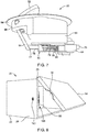
FIG. 1 is a perspective view of a storage bin having a wall-mounted latch mechanism and a door-mounted catch each according to of the present invention; -
FIG. 2 is a perspective view of the latch mechanism ofFIG. 1 ; -
FIG. 3 is a perspective view of the catch ofFIG 1 ; -
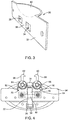
FIG. 4 is a plan view of the latch mechanism ofFIG. 2 in a latched condition; -
FIG. 5 is a perspective view of the latch mechanism ofFIG. 2 in the latched condition; -
FIG. 6 is a plan view of the latch mechanism ofFIG. 2 in an unlatched condition; -
FIG. 7 is a perspective view of the latch mechanism ofFIG. 2 in the unlatched condition; -
FIG. 8 is a perspective view of another storage bin having a wall-mounted latch mechanism and a door-mounted catch each according to another embodiment of the present invention; -
FIG. 9 is a perspective view of the latch mechanism ofFIG. 8 engaged with the catch ofFIG. 3 ; -
FIG. 10 is a plan view of certain components of the latch mechanism ofFIG. 9 in a latched condition; -
FIG. 11 is a perspective view of the latch mechanism ofFIG. 9 in an unlatched condition; -
FIG. 12 is an exploded view of the latch and catch assembly according to the embodiment including a latch mechanism for latch release; and -
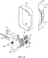
FIG. 13 is an exploded view of the latch and catch assembly according to the embodiment including a push button mechanism for latch release. - The description set forth below in connection with the appended drawings is intended to be a description of various, illustrative embodiments of the present invention. Specific features and functionalities are described in connection with each illustrative embodiment; however, it will be apparent to those skilled in the art that the disclosed embodiments may be practiced without each of those specific features and functionalities. The aspects, features and functions described below in connection with one embodiment are intended to be applicable to the other embodiments described below except where expressly stated or where an aspect, feature or function is incompatible with an embodiment.
- In various embodiments, a storage door is automatically latched upon reaching a closed position by a latch mechanism having spring-loaded geared hooks that engage a door-mounted catch. A user can lift a handle or depress a button, depending on the actuator configuration, to disengage the hooks and open the door. Actuation of the handle or depressing the button ultimately rotates the spring-loaded hooks from their engaged positions permitting the catch to swing away from the latch mechanism by opening of the door. User actuation of the handle or button linearly extends a translating gear rail engaged with the geared hooks and, by forward linear movement of the gear rail, the hooks are rotated from their extended and engaged position to withdrawn and disengaged positions. A keeper maintains the gear rail in the extended position until the catch is returned to the latch mechanism by closure of the door. Upon closure, the catch presses the gear rail rearward from the extended position, overcoming the keeper, and automatically causing the hooks to re-engage the catch.
- A non-limiting example of a
latchable storage bin 20 is shown inFIG. 1 . Thestorage bin 20 may be fixed or mobile in a passenger or crew environment of a vehicle such as an aircraft. Thestorage bin 20 includes amain container 22 and adoor 24 pivotally connected to the main container by ahinge 25. Thestorage bin 20 is illustrated as a box having a generally rectangular shape with planar walls and a rectangular planar hingeddoor 24 hinged at the top of the door. Thestorage bin 20 has an open or closed interior according to the position of thedoor 24 from the illustrated open position to a closed position at which thedoor 24 is brought in contact or at least closely proximal to the forward edges of the walls of the box. - In other embodiments, the
main container 22 anddoor 24 can be of shaped to fit into spaces between other elements in an in-use environment. Thus, thestorage container 22 can each be curved and contoured and can have tapered ends and edges. In such other embodiments the inward side of thedoor 24 and the outward edges of the walls of the box are sufficiently matched to bring alatch mechanism 50, illustrated as mounted in awall 26 of the box, into engagement with acatch 30, illustrated as carried by thedoor 24, into engagement as thedoor 24 is brought to the closed position. - Two expressly illustrated embodiments of a
latch mechanism 100 are shown in the drawings. InFIGS. 1-7 , thelatch mechanism 50 in one embodiment can be disengaged from thecatch 30 by use of a user-actuatable handle 52, permitting thedoor 24 to open. InFIGS. 8-11 , a latch mechanism in another embodiment can be disengaged from thecatch 30 by use of a user-actuatable button. - As shown in
FIG. 2 , thelatch mechanism 50 of the first illustrated embodiment includes abase plate 54 upon which two hooks are pivotally mounted. Two laterally spaced axles or shafts, referenced as afirst axle 56 and a second axle 58 (FIG. 5 ), extend parallel to each other from a first side of thebase plate 54. Thehooks first hook 60 andsecond hook 62, are pivotally mounted on thefirst axle 56 andsecond axle 58 respectively. The hooks are retained on the axles, each by a washer and a retaining ring. - Each hook has a mounting
ring 64 received onto the respective axle. Anarm 66 extends from a first side of the mountingring 64 defined as the forward side when the hook is in the engagement position ofFIG. 4 . Eacharm 66 has a hook 68 at its terminal end opposite the mountingring 64. A second side 70 (FIG. 4 ) of each mountingring 64, defined as the rearward side when the hook is in the engagement position ofFIG. 4 , has gear teeth such that the mountingring 64 defines at least a partially toothed spur gear at least along thesecond side 70 thereof. Thehooks hooks arms 66 extend forward and parallel to each other and the hooks 68 extend laterally into the space between thearms 66. When thehooks FIG. 6 ), thearms 66 withdraw and extend laterally, in opposite lateral directions relative to each other, and the hooks 68 are directed forward. - A
gear rail 72 is movably positioned on thebase plate 54 between thehooks hooks gear rail 72 has aforward rail section 74 extending variably between the mountingrings 64 of thehooks base plate 54. At least theforward rail section 74, along two lateral sides thereof, has laterally extending and longitudinally spaced gear teeth. The gear teeth of thegear rail 72 engage the toothed mounting rings 64 of thehooks gear rail 72 is coordinated with pivoting movement of thehooks FIG. 6 ). Similarly, rearward linear movement of thegear rail 72 is coordinated with pivoting movement of thehooks FIG. 4 ). When thegear rail 72 is in a forward-most first position (FIG. 6 ), thehooks gear rail 72 is in a rearward-most second position (FIG. 4 ), thehooks - A
keeper 80 maintains thegear rail 72 on thebase plate 54. Thekeeper 80 has abridge 82 with lateral tabs by which the keeper is bolted to thebase plate 54. Aclip 84 extends longitudinally forward from the bridge. A contact tip at the forward terminal end of theclip 84 extends toward thegear rail 72 and maintains persistent contact with thegear rail 72 by a spring force of theclip 84. The contact tip is illustrated as curved bend at the forward end of theclip 84. Thegear rail 72 has arearward rail section 76 extending variably between the bridge andbase plate 54, with the lateral tabs of thekeeper 80 adjacent opposite lateral sides of thegear rail 72. - The
gear rail 72 has an outer face directed toward thekeeper 80.Ridges 78 on the outer face register thegear rail 72 relative to thebase plate 54 when thegear rail 72 reaches the forward position (FIG. 6 ) by engaging the contact tip of thekeeper 80. Thekeeper 80 retains thegear rail 72 in the forward position, and thehooks gear rail 72 to overcome the engagement of the contact tip of thekeeper 80 with theridges 78 on the outer face of thegear rail 72. - Each
hook FIG. 4 ) by a respective torsion spring. Afirst torsion spring 90 received onto thefirst axle 56 has opposing ends engaging thebase plate 54 andfirst hook 60 respectively. Asecond torsion spring 92 received onto thesecond axle 58 has opposing ends engaging thebase plate 54 andsecond hook 62 respectively. The torsion springs apply rotational force (torque) to the respective hooks, thereby rotationally biasing thehooks ring 64 of the corresponding hook and thebase 54. As thefirst torsion spring 90 andsecond torsion spring 92 respectively bias thefirst hook 60 andsecond hook 62 toward the engagement positions, thegear rail 72 is biased toward the rearward-most second position ofFIG. 4 . - For use in operating the
latch mechanism 50, the user actuatable handle 52 is pivotally connected to a second side of thebase plate 54, opposite the side on which thegear rail 72 is mounted. As shown inFIGS. 4-7 , alever 94 connected to thehandle 52 pivots relative to thebase plate 54 when thehandle 52 is moved. A forward face of thelever 94 contacts therearward end 77 of thegear rail 72. Thehandle 52 is pivotable relative to thebase plate 54 from the position ofFIGS. 2-5 to the position ofFIGS. 6-7 . The position ofFIGS. 6-7 is termed a first position of thehandle 52, and the position ofFIGS. 2-5 is termed a second position, in correspondence respectively with the forward-most first position (FIG. 6 ) and the rearward-most second position (FIG. 4 ) of thegear rail 72. - When the
handle 52 is in the second position, thelever 94 is pivoted rearward, thegear rail 72 is thereby permitted by thelever 94 to move to the rearward-most position, and thehooks FIG. 4 ) by engagement with thegear rail 72. When thehandle 52 is in the first position, thelever 94 is pivoted forward, thegear rail 72 is pressed forward by thelever 94 to the forward-most position, and thehooks FIG. 6 ) by engagement with thegear rail 72. As thefirst torsion spring 90 andsecond torsion spring 92 respectively bias thefirst hook 60 andsecond hook 62 toward the engagement positions, thegear rail 72 is biased toward the rearward-most second position ofFIG. 4 , thereby biasing thelever 94 rearward and thehandle 52 to the second position (FIGS. 1 ,5 ). - In the illustrated embodiment, the
handle 52 is pivotally connected to the second side of thebase plate 54 by way of a mountingcup 96 by which thelatch mechanism 50 is mounted in thewall 26 of thestorage bin 20 inFIG. 1 . Aflange 98 along an edge of thecup 98 engages thewall 26, with the mountingcup 96 sunken into the wall. Thelatch mechanism 50 is fixed to the wall by engagement of theflange 98 with an exterior side of the wall, and engagement of theflange 98 with an interior side of the wall. Interior side and exterior side refer to the interior and exterior of thestorage bin 20 respectively. When thehandle 52 is in the second position (FIG. 2 ), thehandle 52 is positioned in thecup 96 with the exterior side of thehandle 52 being flush or smoothly aligned with theflange 98 and wall exterior. When thehandle 52 is in the first position (FIG. 4 ), thehandle 52 is pivoted outward from thecup 96. Thecup 96 defines an area greater than an area of thehandle 52. Thus, thecup 96 defines an opening 97 (FIG. 2 ) in any position of thehandle 52 to permit a user to pull thehandle 52 from the second position to the first position to disengage thehooks FIG. 3 ). - The
catch 30 includes a mountingplate 32 for attachment to any element to be engaged with thelatch mechanism 50. Thus, the mountingplate 32 is attached to an edge of thedoor 24 in thestorage bin 20 inFIG. 1 . The mountingplate 32 has afirst opening 34 for thefirst hook 60 and asecond opening 36, laterally spaced from the first opening, for receiving thesecond hook 62. Thefirst opening 34 andsecond opening 36 are dimensioned and spaced to accommodate pivoting movements offirst hook 60 andsecond hook 62 from their engagement positions (FIG. 4 ) to their disengagement positions (FIG. 6 ). Astrike portion 38 of the mounting plate between the first opening and second opening serves to engage thecatch 30 with thehooks catch 30 is brought within the effective reach of thehooks door 24 with respect to the main container 22 (FIG. 1 ), pivoting of thehooks FIG. 4 ) captures thestrike portion 38 of the mountingplate 32 between thearms 66, with thearms 66 extending through theopenings catch 30 from thelatch mechanism 50. Thecatch 30 includes a dishedgrip 40 extending from the mountingplate 32 for use in manipulating thedoor 24 by hand. The dishedgrip 40 is sunken into an edge of thedoor 24 in the example ofFIG. 1 . - As shown in
FIG. 6 , when thehooks FIG. 6 ), thegear rail 72 is in the forward-most position, and theforward end 75 of thegear rail 72 extends forward from thelatch mechanism 50. This defines an unlatched or open condition of thelatch mechanism 50. Thelatch mechanism 50 automatically latches when the catch is brought within the reach of thehooks FIG. 6 ), thekeeper 80 is engaged with theridges 78 on thegear rail 72 thereby maintaining thehooks latch mechanism 50, for example as thedoor 24 hinges toward themain container 22 for closure of thestorage bin 20, the strike portion of the mounting plate of the catch contacts theforward end 75 of thegear rail 72 and presses thegear rail 72 rearward into thelatch mechanism 50. With assistance from the biasing of the torsion springs, this overcomes the engagement of the contact tip of thekeeper 80 with theridges 78 on thegear rail 72 and automatically causes thehooks FIG. 4 ) by engagement with thegear rail 72. The torsion springs may cause a light snapping closure action as thegear rail 72 retracts to the rearward-most position. This defines a latched or closed condition of the latch mechanism 50 (FIG. 4 ), and a latched and closed condition of thedoor 24 andstorage bin 20 when thelatch mechanism 50 and catch 30 are used as in the example ofFIG. 1 . - Throughout transitions between engagement and disengagement of the
latch mechanism 50 with the catch, thefirst hook 60 andsecond hook 62 are biased toward their engagement positions by the torsion springs 90 and 92. From the latched or closed condition of the latch mechanism 50 (FIG. 4 ), in which thehooks gear rail 72 is retracted to this rearward-most position (FIGS, 2 and4-5 ), thehandle 52 can be pivoted outward (FIG. 7 ) from thecup 96 by user action such that: thelever 94 presses thegear rail 72 forward; thegear rail 72 rotates thehooks FIGS. 6-7 ) against the biasing force of the torsion springs; and theforward end 75 of thegear rail 72 pushes the catch away from thelatch mechanism 50, opening thestorage bin 20 in the in-use example ofFIG. 1 . In such action, the torsion springs are overcome to permit thelatch mechanism 50 to assume the unlatched condition, and thekeeper 80 maintains thelatch mechanism 50 in the unlatched condition by engaging theridges 78 on the outer face of thegear rail 72 once the forward most position of thegear rail 72 is reached. - The
latch mechanism 50 and catch 30 provide a clean, elegant appearance for thestorage bin 20 or other stowage container where used. Thehandle 52 is flush or smoothly aligned with theflange 98 andwall 26 of thebin 20, and the dishedgrip 40 is sunken into the edge of thedoor 24 in the example ofFIG. 1 . Aprotective housing 55 is attached to thebase plate 54 opposite the mountingcup 96, encasing moving components from exposure in the interior of the storage bin 20 (FIG. 1 ). - The
storage bin 20 is shown inFIG. 8 with alatch mechanism 100 according to another embodiment. As shown inFIGS. 9 and 10 , thelatch mechanism 100 has a user-actuatable pin 102 that can linearly actuated to disengage thelatch mechanism 100 from the catch, permitting thedoor 24 to open.FIG. 9 shows thepin 102 in an extended position, corresponding to a latched or closed condition of thelatch mechanism 100.FIG. 11 shows thepin 102 in an un-extended position, corresponding to an unlatched or open condition of thelatch mechanism 100. A terminal end of thepin 102, referenced as abutton 103, extends outward from thebase plate 104 of thelatch mechanism 100. Thebutton 103 can be pressed from the extended position to unlatch themechanism 100, causing thehooks - In the extended position of the
pin 102, thebutton 103 may extend from a hole in thewall 26 of the bin 20 (FIG. 8 ). Upon pressing, thebutton 103 can be positioned flush with thewall 26 to open thelatch mechanism 100. In another example, thebutton 103 may be flush or sunken relative to the exterior surface of thewall 26 in the extended position of thepin 102, such that pressing thebutton 103 inward from the exterior surface opens thelatch mechanism 100. - The following descriptions of the
latch mechanism 100 rely on the above descriptions of thelatch mechanism 50 with regard to features that are similar in the two mechanisms, while drawing particular attention to features that are different. Like reference numbers are used in the following for features sufficiently described above. - As shown in
FIGS. 9-11 , thelatch mechanism 100 of the second illustrated embodiment includes thebase plate 104 upon which thefirst hook 60 andsecond hook 62 are pivotally mounted on thefirst axle 56 andsecond axle 58 respectively. Laterally arrangedspacers 106 extend from thebase plate 104 for mounting thelatch mechanism 100 to the interior of the wall of thelatchable storage bin 20. Theprotective housing 55 is attached to thebase plate 104 opposite thespacers 106, encasing the moving components from exposure in the interior of thestorage bin 20. - The
latch mechanism 100 ofFIGS. 9-11 includes the user-actuatable pin 102 for extending thegear rail 116 from the rearward-most position ofFIG. 10 , at which thehooks latch mechanism 100 is in a latched condition, to the forward-most position ofFIG. 11 , at which thehooks latch mechanism 100 is in an unlatched condition. In thelatch mechanism 100, a partially toothedfirst gear 110 is pivotally mounted on thebase plate 104 rearward of thefirst hook 60, and a partially toothedsecond gear 112 is pivotally mounted on thebase plate 104 rearward of thesecond hook 62. Thegears second hooks gear rail 116 linearly. - The gear teeth of the
gear rail 116 are distributed along both lateral sides sufficiently to engage both the relatively forward first andsecond hooks second gears keeper 80 andgear rail 116 of thelatch mechanism 100 ofFIGS. 9-11 may have different dimensions relative to thekeeper 80 andgear rail 72 of thelatch mechanism 50 ofFIGS. 4-6 while providing similar functionalities. Thegear rail 72 of thelatch mechanism 50 ofFIGS. 4-7 is user actuated by thehandle 52 andlever 94, whereas thegear rail 116 of thelatch mechanism 100 ofFIGS. 9-11 is user actuated by thepin 102 andfirst gear 110. - The
second gear 112 is pivotally mounted on a fixed axle. Thefirst gear 110 is slidably mounted on thepin 102. In the latched condition (FIG. 9 ), thepin 102 extends from thelatch mechanism 100 through an internally threaded bore of a fixedbarrel 114. For example, the fixedbarrel 114 may be mounted in the hole in thewall 26 of thestorage bin 20 through which thepin 102 extends. Thefirst gear 110 and pin 102 are shown without the fixed barrel inFIG. 10 for illustration purposes. When thebutton 103 is pressed by user action, thepin 102 moves linearly toward thebase plate 104 and rotates by engagement with the internally threaded bore of the fixedbarrel 114. This rotates thefirst gear 110, retracting thegear rail 116, which rotates thehooks FIG. 11 ) against the biasing force of the torsion springs. Theforward end 118 of thegear rail 116 pushes thecatch 30 away from thelatch mechanism 100, opening thedoor 22 of thestorage bin 20 in the in-use example ofFIG. 8 . In such action, the torsion springs are overcome to permit thelatch mechanism 100 to assume the unlatched condition, and thekeeper 80 maintains thelatch mechanism 100 in the unlatched condition by engaging theridges 120 on the outer face of thegear rail 116 once the forward most position of thegear rail 116 is reached. - When the
gear rail 116 is returned rearward to the rearward-most position (FIG. 10 ), for example as thecatch 30 approaches thelatch mechanism 100 upon closure of thedoor 24, thegear rail 116 is pressed rearward and automatically causes thehooks gear rail 116 also counter rotates thefirst gear 110, thereby re-extending thepin 102 by way of its engagement with the internally threaded bore of the fixedbarrel 114. - In the
latch mechanism 50 and thelatch mechanism 100, a sensor may be included to detect the status of the mechanism with regard to engagement with thecatch 30 for example, and closure of thedoor 24. The sensor may alert crew members for example in an aircraft as to the status of the latch mechanism and door for safety and security purposes. - While the foregoing description provides embodiments of the invention by way of example only, it is envisioned that other embodiments that are within the scope of the invention as defined by the appended claims may perform similar functions and/or achieve similar results.
Claims (13)
- A latch and catch assembly, comprising:a catch (30) attachable to a first structure; anda latch mechanism (50, 100) attachable to a second structure, the latch mechanism (50, 100) and the catch (30) cooperating to secure the first structure relative to the second structure, the latch mechanism (50, 100) comprising:i) first and second hooks (60, 62) mounted for pivoting movement between an engagement position for engaging with the catch (30) and a disengagement position for disengaging from the catch (30);ii) a translating gear rail (72, 116) positioned between the first and second hooks (60, 62), the translating gear rail (72, 116) engaged on opposing lateral sides thereof with the respective first and second hooks (60, 62); andiii) an actuator mechanism operable for driving movement of the translating gear rail (72, 116) to drive simultaneous pivoting movement of the first and second hooks (60, 62) apart, preferably in opposite directions to drive ends of the first and second hooks (60, 62) apart, toward their disengagement position.
- The latch and catch assembly according to claim 1, wherein each of the first and second hooks (60, 62) are rotatably mounted on a shaft (56, 58) coupled to a base plate (54, 104), and wherein each of the first and second hooks (60, 62) are rotationally-biased in a direction toward their engagement position by a torsion spring (90, 92) mounted on the shaft (56, 58) and engaging the respective one of the first and second hooks (60, 62).
- The latch and catch assembly according to claim 2, wherein the translating gear rail (72, 116) is movably positioned on the base plate (54, 104) between the first and second hooks (60, 62) and has longitudinally-spaced gear teeth formed on the opposing lateral sides thereof engaging gear teeth on mounting rings (64) of the first and second hooks (60, 62), the gear teeth of the translating gear rail (72, 116) engaging the gear teeth of the mounting rings (64) such that linear movement of the translating gear rail (72, 116) is coordinated with pivoting movement of the first and second hooks (60, 62).
- The latch and catch assembly according to claim 3, wherein movement of the translating gear rail (72, 116) in a first direction drives pivoting movement of the first and second hooks (60, 62) toward their disengagement position, and movement of the translating gear rail (72, 116) in a second direction opposite the first direction drives the first and second hooks (60, 62) toward their engagement position.
- The latch and catch assembly according to one or more of the preceding claims, wherein each of the first and second hooks (60, 62) includes a pivotally-attached end and a hooked end, and wherein the hooked ends are positioned spaced apart and facing each other when the first and second hooks (60, 62) are in their engagement position.
- The latch and catch assembly according to one or more of the preceding claims, wherein the catch (30) comprises a strike plate (38, 32) positioned between first and second spaced openings (34, 36), the translating gear rail (72, 116) adapted to contact the strike plate (38, 32) to move the translating gear rail (72, 116) away from the catch (30) to drive the first and second hooks (60, 62) toward their engagement position, and the first and second hooks (60, 62) adapted to be received in the respective first and second openings (34, 36) to engage the first and second hooks (60, 62) with the catch (30) in their engagement position.
- The latch and catch assembly according to one or more of the preceding claims, wherein the latch mechanism (50, 100) is mountable on an interior wall of a storage bin (20) and the catch (30) is mountable on a door (24) pivotally attached to the storage bin (20), whereby, when the first and second hooks (60, 62) engage the catch (30) in their engagement position, the door (24) is latched in a closed condition.
- The latch and catch assembly according to one or more of the preceding claims, wherein the latch mechanism (50, 100) further comprises a base plate (54, 104) and keeper (80) attached to the base plate (54, 104), the keeper (80) maintaining persistent contact with the translating gear rail (72, 116) by a spring force of a clip (84), and the translating gear rail (72, 116) having ridges (78, 120) on an outer face thereof within which the clip (84) engages to maintain the first and second hooks (60, 62) in their disengagement position.
- The latch and catch assembly according to one or more of the preceding claims, the actuator mechanism comprises a user-actuatable pin (102) for moving the translating gear rail (72, 116) toward the catch (30), thereby pivoting the first and second hooks (60, 62) toward their disengagement position.
- The latch and catch assembly according to one or more of the preceding claims, wherein the actuator mechanism comprises an actuatable handle (52), wherein pivoting the handle (52) causes the translating gear rail (72, 116) to move toward the catch (30).
- A cabinet assembly, comprising a latch and catch assemly according to one or more of the preceding claims:wherein the second structure is embodied as a cabinet having a latch mechanism mounted on an inner wall of the cabinet; andwherein the first structure is embodied as a door pivotally-attached to the cabinet and having a catch (30) mounted on the door; andwherein a portion of the latch mechanism engages with the catch (30) to hold the door in a closed condition; andwherein the latch mechanism comprises a base plate (54, 104): and whereini) the first and second hooks (60, 62) are mounted on shafts of the base plate (54, 104); andii) the translating gear rail (72, 116) is positioned to coordinate translating gear rail (72, 116) movement with pivoting movement of the first and second hooks (60, 62).
- The cabinet assembly according to claim 11, wherein each of the first and second hooks (60, 62) includes a pivotally-attached end and a hooked end, and wherein the hooked ends are ramped such that engagement of the hooked ends with the catch (30) deflects the first and second hooks (60, 62) toward their disengagement position.
- The cabinet assembly of claims 10 and 11, the catch (30) thereby pushing the catch (30) away from the latch mechanism (50, 100) and opening the door (24).
Applications Claiming Priority (1)
| Application Number | Priority Date | Filing Date | Title |
|---|---|---|---|
| US16/419,073 US11421449B2 (en) | 2019-05-22 | 2019-05-22 | Latch and catch assembly |
Publications (2)
| Publication Number | Publication Date |
|---|---|
| EP3741939A1 true EP3741939A1 (en) | 2020-11-25 |
| EP3741939B1 EP3741939B1 (en) | 2023-01-25 |
Family
ID=68916364
Family Applications (1)
| Application Number | Title | Priority Date | Filing Date |
|---|---|---|---|
| EP19215966.3A Active EP3741939B1 (en) | 2019-05-22 | 2019-12-13 | Latch and catch assembly |
Country Status (4)
| Country | Link |
|---|---|
| US (1) | US11421449B2 (en) |
| EP (1) | EP3741939B1 (en) |
| CN (1) | CN111980508B (en) |
| CA (1) | CA3063948A1 (en) |
Cited By (1)
| Publication number | Priority date | Publication date | Assignee | Title |
|---|---|---|---|---|
| US12366091B2 (en) * | 2022-10-27 | 2025-07-22 | Vision Engineering | Compact gear lock |
Families Citing this family (5)
| Publication number | Priority date | Publication date | Assignee | Title |
|---|---|---|---|---|
| CN112900988B (en) * | 2021-02-08 | 2023-08-15 | 宁波生久科技有限公司 | Cabinet door self-locking quick installation mechanism |
| GB2630872A (en) | 2022-05-18 | 2024-12-11 | Briggs And Riley Traveware Llc | Compression and expansion locking device for luggage containing same |
| CN115492465B (en) * | 2022-09-05 | 2023-08-08 | 南昌欧迈斯智能科技有限公司 | Handle structure and intelligent lock |
| EP4438475B1 (en) * | 2023-03-29 | 2026-05-06 | Airbus Operations GmbH | Improved latch mechanism for an overhead stowage compartment |
| CN118242554A (en) * | 2024-05-29 | 2024-06-25 | 中电工研(徐州)氢能源科技有限公司 | But solid-state hydrogen storage equipment of modularization production ferrotitanium system |
Citations (5)
| Publication number | Priority date | Publication date | Assignee | Title |
|---|---|---|---|---|
| US1320444A (en) * | 1919-11-04 | Combination-lock | ||
| US1549505A (en) * | 1923-11-05 | 1925-08-11 | Hartmann Trunk Co | Trunk latch |
| JPS54154997U (en) * | 1978-04-15 | 1979-10-27 | ||
| CA2593664A1 (en) * | 2007-06-26 | 2007-10-05 | Vanguard Plastics Ltd. | Dual-hook locking assembly |
| US20070259551A1 (en) * | 2007-07-03 | 2007-11-08 | Vanguard Plastics Ltd. | Dual-hook locking assembly |
Family Cites Families (26)
| Publication number | Priority date | Publication date | Assignee | Title |
|---|---|---|---|---|
| US56347A (en) * | 1866-07-17 | Improved sash-fastening | ||
| US324883A (en) * | 1885-08-25 | Sash-fastener | ||
| US131321A (en) * | 1872-09-10 | Improvement in fasteners for the meeting-rails of sashes | ||
| US385904A (en) * | 1888-07-10 | Sash-holder | ||
| US413355A (en) * | 1889-10-22 | Sash-fastener | ||
| US335175A (en) * | 1886-02-02 | Xchaeles r reginald blathwayt | ||
| US1632195A (en) * | 1923-06-25 | 1927-06-14 | Hartmann Trunk Co | Trunk lock |
| US2506943A (en) * | 1947-07-28 | 1950-05-09 | Tyler Fixture Corp | Latch |
| US3175376A (en) * | 1961-07-17 | 1965-03-30 | Adams Rite Mfg Company | Lock mechanism |
| US3423968A (en) * | 1967-04-10 | 1969-01-28 | Master Lock Co | Detachable locking devices |
| FR1585639A (en) * | 1968-08-01 | 1970-01-30 | ||
| US4738126A (en) * | 1986-05-16 | 1988-04-19 | Haberle Bruce V | Releasable locking device |
| US5620216A (en) * | 1992-10-30 | 1997-04-15 | Fuller; Mark W. | Lock mechanism |
| US5544924A (en) * | 1994-01-28 | 1996-08-13 | Paster; Max | Security mechanism for securing a movable closure |
| DE19946773C2 (en) * | 1999-09-29 | 2003-06-05 | Rittal Gmbh & Co Kg | Locking device for a control cabinet |
| GB0016854D0 (en) * | 2000-07-11 | 2000-08-30 | Apw Electronics Ltd | Door latching mechanism |
| AU2003252202B2 (en) * | 2002-10-04 | 2008-09-25 | Azuma Pty Ltd | A Sliding Door Lock |
| US7040671B2 (en) * | 2003-01-28 | 2006-05-09 | Jyh-Huey Su, legal representative | Lock assembly with two hook devices |
| US7178839B2 (en) * | 2003-06-09 | 2007-02-20 | Imperial Usa, Ltd. | Latch assembly for sliding doors |
| US20060071478A1 (en) * | 2004-10-04 | 2006-04-06 | Fasco Die Cast Inc. | Multi-point sliding door |
| US7228719B2 (en) * | 2004-12-22 | 2007-06-12 | Azuma Designs Pty Limited | Sliding door lock |
| US7837241B2 (en) * | 2007-04-19 | 2010-11-23 | Union Tool Exporters, Ltd. | Two point lock for doors and windows |
| US8038183B2 (en) * | 2007-11-26 | 2011-10-18 | Grant Atkinson | Multi-point lock assembly |
| CN102053676B (en) * | 2009-10-30 | 2014-11-12 | 鸿富锦精密工业(深圳)有限公司 | Computer chassis |
| WO2011113212A1 (en) * | 2010-03-19 | 2011-09-22 | Zhi Jun Dong | Locking device for windows and doors |
| GB2520666B (en) * | 2013-08-02 | 2020-09-16 | Surelock Mcgill Ltd | Lock System |
-
2019
- 2019-05-22 US US16/419,073 patent/US11421449B2/en active Active
- 2019-11-29 CA CA3063948A patent/CA3063948A1/en active Pending
- 2019-12-13 CN CN201911284641.3A patent/CN111980508B/en active Active
- 2019-12-13 EP EP19215966.3A patent/EP3741939B1/en active Active
Patent Citations (5)
| Publication number | Priority date | Publication date | Assignee | Title |
|---|---|---|---|---|
| US1320444A (en) * | 1919-11-04 | Combination-lock | ||
| US1549505A (en) * | 1923-11-05 | 1925-08-11 | Hartmann Trunk Co | Trunk latch |
| JPS54154997U (en) * | 1978-04-15 | 1979-10-27 | ||
| CA2593664A1 (en) * | 2007-06-26 | 2007-10-05 | Vanguard Plastics Ltd. | Dual-hook locking assembly |
| US20070259551A1 (en) * | 2007-07-03 | 2007-11-08 | Vanguard Plastics Ltd. | Dual-hook locking assembly |
Cited By (1)
| Publication number | Priority date | Publication date | Assignee | Title |
|---|---|---|---|---|
| US12366091B2 (en) * | 2022-10-27 | 2025-07-22 | Vision Engineering | Compact gear lock |
Also Published As
| Publication number | Publication date |
|---|---|
| US20200370341A1 (en) | 2020-11-26 |
| CN111980508B (en) | 2023-06-27 |
| CN111980508A (en) | 2020-11-24 |
| US11421449B2 (en) | 2022-08-23 |
| CA3063948A1 (en) | 2020-11-22 |
| EP3741939B1 (en) | 2023-01-25 |
Similar Documents
| Publication | Publication Date | Title |
|---|---|---|
| EP3741939B1 (en) | Latch and catch assembly | |
| US12180759B2 (en) | Child proof latch and method of fitting | |
| CA2711876C (en) | Sliding door handle and latch | |
| US8876171B2 (en) | Lock for a luggage box | |
| US11959307B2 (en) | Lever action automatic shootbolt operator with magnetically-triggered locking mechanism | |
| EP3112218B1 (en) | Roof box for vehicles | |
| US6009932A (en) | Push to exit, pull to enter latch assembly for screen door | |
| US7377076B2 (en) | Single-action egress lock for a sliding door | |
| US20120272695A1 (en) | Door handle assembly for vehicle compartment | |
| TW201344025A (en) | Handle-actuated locks | |
| EP3423652A1 (en) | Latch arrangement having a handle | |
| EP3918163B1 (en) | Panic bar latch release assembly | |
| US20100050524A1 (en) | Motorized door opener for a vehicle | |
| EP4119753B1 (en) | Concealed door hinge with shifting pivot point | |
| EP3529438B1 (en) | Bin latch | |
| EP1999324B1 (en) | Door handle lock assembly with automatic lock and retract | |
| GB2304796A (en) | A motor vehicle door lock | |
| CN116335497A (en) | Doors with integrated opening and closing mechanisms | |
| EP1179108B1 (en) | Latch | |
| EP4299436B1 (en) | A door locking assembly for an aircraft | |
| US20070245517A1 (en) | Door check assembly | |
| CA2619389A1 (en) | Global side door latch | |
| JP2017533139A (en) | Overhead storage box latch system | |
| RU208041U1 (en) | Aircraft sliding door locking device | |
| US1770917A (en) | Latch for automobile doors |
Legal Events
| Date | Code | Title | Description |
|---|---|---|---|
| PUAI | Public reference made under article 153(3) epc to a published international application that has entered the european phase |
Free format text: ORIGINAL CODE: 0009012 |
|
| STAA | Information on the status of an ep patent application or granted ep patent |
Free format text: STATUS: THE APPLICATION HAS BEEN PUBLISHED |
|
| AK | Designated contracting states |
Kind code of ref document: A1 Designated state(s): AL AT BE BG CH CY CZ DE DK EE ES FI FR GB GR HR HU IE IS IT LI LT LU LV MC MK MT NL NO PL PT RO RS SE SI SK SM TR |
|
| AX | Request for extension of the european patent |
Extension state: BA ME |
|
| STAA | Information on the status of an ep patent application or granted ep patent |
Free format text: STATUS: REQUEST FOR EXAMINATION WAS MADE |
|
| 17P | Request for examination filed |
Effective date: 20210525 |
|
| RBV | Designated contracting states (corrected) |
Designated state(s): AL AT BE BG CH CY CZ DE DK EE ES FI FR GB GR HR HU IE IS IT LI LT LU LV MC MK MT NL NO PL PT RO RS SE SI SK SM TR |
|
| GRAP | Despatch of communication of intention to grant a patent |
Free format text: ORIGINAL CODE: EPIDOSNIGR1 |
|
| STAA | Information on the status of an ep patent application or granted ep patent |
Free format text: STATUS: GRANT OF PATENT IS INTENDED |
|
| INTG | Intention to grant announced |
Effective date: 20221019 |
|
| GRAS | Grant fee paid |
Free format text: ORIGINAL CODE: EPIDOSNIGR3 |
|
| GRAA | (expected) grant |
Free format text: ORIGINAL CODE: 0009210 |
|
| STAA | Information on the status of an ep patent application or granted ep patent |
Free format text: STATUS: THE PATENT HAS BEEN GRANTED |
|
| AK | Designated contracting states |
Kind code of ref document: B1 Designated state(s): AL AT BE BG CH CY CZ DE DK EE ES FI FR GB GR HR HU IE IS IT LI LT LU LV MC MK MT NL NO PL PT RO RS SE SI SK SM TR |
|
| REG | Reference to a national code |
Ref country code: GB Ref legal event code: FG4D |
|
| REG | Reference to a national code |
Ref country code: CH Ref legal event code: EP |
|
| REG | Reference to a national code |
Ref country code: AT Ref legal event code: REF Ref document number: 1546017 Country of ref document: AT Kind code of ref document: T Effective date: 20230215 Ref country code: IE Ref legal event code: FG4D |
|
| REG | Reference to a national code |
Ref country code: DE Ref legal event code: R096 Ref document number: 602019024753 Country of ref document: DE |
|
| REG | Reference to a national code |
Ref country code: LT Ref legal event code: MG9D |
|
| REG | Reference to a national code |
Ref country code: NL Ref legal event code: MP Effective date: 20230125 |
|
| REG | Reference to a national code |
Ref country code: AT Ref legal event code: MK05 Ref document number: 1546017 Country of ref document: AT Kind code of ref document: T Effective date: 20230125 |
|
| PG25 | Lapsed in a contracting state [announced via postgrant information from national office to epo] |
Ref country code: NL Free format text: LAPSE BECAUSE OF FAILURE TO SUBMIT A TRANSLATION OF THE DESCRIPTION OR TO PAY THE FEE WITHIN THE PRESCRIBED TIME-LIMIT Effective date: 20230125 |
|
| P01 | Opt-out of the competence of the unified patent court (upc) registered |
Effective date: 20230608 |
|
| PG25 | Lapsed in a contracting state [announced via postgrant information from national office to epo] |
Ref country code: RS Free format text: LAPSE BECAUSE OF FAILURE TO SUBMIT A TRANSLATION OF THE DESCRIPTION OR TO PAY THE FEE WITHIN THE PRESCRIBED TIME-LIMIT Effective date: 20230125 Ref country code: PT Free format text: LAPSE BECAUSE OF FAILURE TO SUBMIT A TRANSLATION OF THE DESCRIPTION OR TO PAY THE FEE WITHIN THE PRESCRIBED TIME-LIMIT Effective date: 20230525 Ref country code: NO Free format text: LAPSE BECAUSE OF FAILURE TO SUBMIT A TRANSLATION OF THE DESCRIPTION OR TO PAY THE FEE WITHIN THE PRESCRIBED TIME-LIMIT Effective date: 20230425 Ref country code: LV Free format text: LAPSE BECAUSE OF FAILURE TO SUBMIT A TRANSLATION OF THE DESCRIPTION OR TO PAY THE FEE WITHIN THE PRESCRIBED TIME-LIMIT Effective date: 20230125 Ref country code: LT Free format text: LAPSE BECAUSE OF FAILURE TO SUBMIT A TRANSLATION OF THE DESCRIPTION OR TO PAY THE FEE WITHIN THE PRESCRIBED TIME-LIMIT Effective date: 20230125 Ref country code: HR Free format text: LAPSE BECAUSE OF FAILURE TO SUBMIT A TRANSLATION OF THE DESCRIPTION OR TO PAY THE FEE WITHIN THE PRESCRIBED TIME-LIMIT Effective date: 20230125 Ref country code: ES Free format text: LAPSE BECAUSE OF FAILURE TO SUBMIT A TRANSLATION OF THE DESCRIPTION OR TO PAY THE FEE WITHIN THE PRESCRIBED TIME-LIMIT Effective date: 20230125 Ref country code: AT Free format text: LAPSE BECAUSE OF FAILURE TO SUBMIT A TRANSLATION OF THE DESCRIPTION OR TO PAY THE FEE WITHIN THE PRESCRIBED TIME-LIMIT Effective date: 20230125 |
|
| PG25 | Lapsed in a contracting state [announced via postgrant information from national office to epo] |
Ref country code: SE Free format text: LAPSE BECAUSE OF FAILURE TO SUBMIT A TRANSLATION OF THE DESCRIPTION OR TO PAY THE FEE WITHIN THE PRESCRIBED TIME-LIMIT Effective date: 20230125 Ref country code: PL Free format text: LAPSE BECAUSE OF FAILURE TO SUBMIT A TRANSLATION OF THE DESCRIPTION OR TO PAY THE FEE WITHIN THE PRESCRIBED TIME-LIMIT Effective date: 20230125 Ref country code: IS Free format text: LAPSE BECAUSE OF FAILURE TO SUBMIT A TRANSLATION OF THE DESCRIPTION OR TO PAY THE FEE WITHIN THE PRESCRIBED TIME-LIMIT Effective date: 20230525 Ref country code: GR Free format text: LAPSE BECAUSE OF FAILURE TO SUBMIT A TRANSLATION OF THE DESCRIPTION OR TO PAY THE FEE WITHIN THE PRESCRIBED TIME-LIMIT Effective date: 20230426 Ref country code: FI Free format text: LAPSE BECAUSE OF FAILURE TO SUBMIT A TRANSLATION OF THE DESCRIPTION OR TO PAY THE FEE WITHIN THE PRESCRIBED TIME-LIMIT Effective date: 20230125 |
|
| REG | Reference to a national code |
Ref country code: DE Ref legal event code: R097 Ref document number: 602019024753 Country of ref document: DE |
|
| PG25 | Lapsed in a contracting state [announced via postgrant information from national office to epo] |
Ref country code: SM Free format text: LAPSE BECAUSE OF FAILURE TO SUBMIT A TRANSLATION OF THE DESCRIPTION OR TO PAY THE FEE WITHIN THE PRESCRIBED TIME-LIMIT Effective date: 20230125 Ref country code: RO Free format text: LAPSE BECAUSE OF FAILURE TO SUBMIT A TRANSLATION OF THE DESCRIPTION OR TO PAY THE FEE WITHIN THE PRESCRIBED TIME-LIMIT Effective date: 20230125 Ref country code: EE Free format text: LAPSE BECAUSE OF FAILURE TO SUBMIT A TRANSLATION OF THE DESCRIPTION OR TO PAY THE FEE WITHIN THE PRESCRIBED TIME-LIMIT Effective date: 20230125 Ref country code: DK Free format text: LAPSE BECAUSE OF FAILURE TO SUBMIT A TRANSLATION OF THE DESCRIPTION OR TO PAY THE FEE WITHIN THE PRESCRIBED TIME-LIMIT Effective date: 20230125 Ref country code: CZ Free format text: LAPSE BECAUSE OF FAILURE TO SUBMIT A TRANSLATION OF THE DESCRIPTION OR TO PAY THE FEE WITHIN THE PRESCRIBED TIME-LIMIT Effective date: 20230125 |
|
| PG25 | Lapsed in a contracting state [announced via postgrant information from national office to epo] |
Ref country code: SK Free format text: LAPSE BECAUSE OF FAILURE TO SUBMIT A TRANSLATION OF THE DESCRIPTION OR TO PAY THE FEE WITHIN THE PRESCRIBED TIME-LIMIT Effective date: 20230125 |
|
| PLBE | No opposition filed within time limit |
Free format text: ORIGINAL CODE: 0009261 |
|
| STAA | Information on the status of an ep patent application or granted ep patent |
Free format text: STATUS: NO OPPOSITION FILED WITHIN TIME LIMIT |
|
| 26N | No opposition filed |
Effective date: 20231026 |
|
| PG25 | Lapsed in a contracting state [announced via postgrant information from national office to epo] |
Ref country code: SI Free format text: LAPSE BECAUSE OF FAILURE TO SUBMIT A TRANSLATION OF THE DESCRIPTION OR TO PAY THE FEE WITHIN THE PRESCRIBED TIME-LIMIT Effective date: 20230125 |
|
| PG25 | Lapsed in a contracting state [announced via postgrant information from national office to epo] |
Ref country code: IT Free format text: LAPSE BECAUSE OF FAILURE TO SUBMIT A TRANSLATION OF THE DESCRIPTION OR TO PAY THE FEE WITHIN THE PRESCRIBED TIME-LIMIT Effective date: 20230125 |
|
| REG | Reference to a national code |
Ref country code: CH Ref legal event code: PL |
|
| PG25 | Lapsed in a contracting state [announced via postgrant information from national office to epo] |
Ref country code: LU Free format text: LAPSE BECAUSE OF NON-PAYMENT OF DUE FEES Effective date: 20231213 |
|
| PG25 | Lapsed in a contracting state [announced via postgrant information from national office to epo] |
Ref country code: MC Free format text: LAPSE BECAUSE OF FAILURE TO SUBMIT A TRANSLATION OF THE DESCRIPTION OR TO PAY THE FEE WITHIN THE PRESCRIBED TIME-LIMIT Effective date: 20230125 |
|
| REG | Reference to a national code |
Ref country code: BE Ref legal event code: MM Effective date: 20231231 |
|
| PG25 | Lapsed in a contracting state [announced via postgrant information from national office to epo] |
Ref country code: MC Free format text: LAPSE BECAUSE OF FAILURE TO SUBMIT A TRANSLATION OF THE DESCRIPTION OR TO PAY THE FEE WITHIN THE PRESCRIBED TIME-LIMIT Effective date: 20230125 Ref country code: LU Free format text: LAPSE BECAUSE OF NON-PAYMENT OF DUE FEES Effective date: 20231213 |
|
| REG | Reference to a national code |
Ref country code: IE Ref legal event code: MM4A |
|
| PG25 | Lapsed in a contracting state [announced via postgrant information from national office to epo] |
Ref country code: IE Free format text: LAPSE BECAUSE OF NON-PAYMENT OF DUE FEES Effective date: 20231213 |
|
| PG25 | Lapsed in a contracting state [announced via postgrant information from national office to epo] |
Ref country code: BE Free format text: LAPSE BECAUSE OF NON-PAYMENT OF DUE FEES Effective date: 20231231 |
|
| PG25 | Lapsed in a contracting state [announced via postgrant information from national office to epo] |
Ref country code: CH Free format text: LAPSE BECAUSE OF NON-PAYMENT OF DUE FEES Effective date: 20231231 |
|
| PG25 | Lapsed in a contracting state [announced via postgrant information from national office to epo] |
Ref country code: IE Free format text: LAPSE BECAUSE OF NON-PAYMENT OF DUE FEES Effective date: 20231213 Ref country code: CH Free format text: LAPSE BECAUSE OF NON-PAYMENT OF DUE FEES Effective date: 20231231 Ref country code: BE Free format text: LAPSE BECAUSE OF NON-PAYMENT OF DUE FEES Effective date: 20231231 |
|
| PG25 | Lapsed in a contracting state [announced via postgrant information from national office to epo] |
Ref country code: BG Free format text: LAPSE BECAUSE OF FAILURE TO SUBMIT A TRANSLATION OF THE DESCRIPTION OR TO PAY THE FEE WITHIN THE PRESCRIBED TIME-LIMIT Effective date: 20230125 |
|
| PG25 | Lapsed in a contracting state [announced via postgrant information from national office to epo] |
Ref country code: BG Free format text: LAPSE BECAUSE OF FAILURE TO SUBMIT A TRANSLATION OF THE DESCRIPTION OR TO PAY THE FEE WITHIN THE PRESCRIBED TIME-LIMIT Effective date: 20230125 |
|
| PG25 | Lapsed in a contracting state [announced via postgrant information from national office to epo] |
Ref country code: CY Free format text: LAPSE BECAUSE OF FAILURE TO SUBMIT A TRANSLATION OF THE DESCRIPTION OR TO PAY THE FEE WITHIN THE PRESCRIBED TIME-LIMIT; INVALID AB INITIO Effective date: 20191213 |
|
| PG25 | Lapsed in a contracting state [announced via postgrant information from national office to epo] |
Ref country code: HU Free format text: LAPSE BECAUSE OF FAILURE TO SUBMIT A TRANSLATION OF THE DESCRIPTION OR TO PAY THE FEE WITHIN THE PRESCRIBED TIME-LIMIT; INVALID AB INITIO Effective date: 20191213 |
|
| PG25 | Lapsed in a contracting state [announced via postgrant information from national office to epo] |
Ref country code: TR Free format text: LAPSE BECAUSE OF FAILURE TO SUBMIT A TRANSLATION OF THE DESCRIPTION OR TO PAY THE FEE WITHIN THE PRESCRIBED TIME-LIMIT Effective date: 20230125 |
|
| PGFP | Annual fee paid to national office [announced via postgrant information from national office to epo] |
Ref country code: DE Payment date: 20251126 Year of fee payment: 7 |
|
| PGFP | Annual fee paid to national office [announced via postgrant information from national office to epo] |
Ref country code: GB Payment date: 20251120 Year of fee payment: 7 |
|
| PGFP | Annual fee paid to national office [announced via postgrant information from national office to epo] |
Ref country code: FR Payment date: 20251119 Year of fee payment: 7 |