EP3741717A1 - Conveying device, packaging machine having such a conveying device and method of cooling such a conveying device - Google Patents
Conveying device, packaging machine having such a conveying device and method of cooling such a conveying device Download PDFInfo
- Publication number
- EP3741717A1 EP3741717A1 EP19175424.1A EP19175424A EP3741717A1 EP 3741717 A1 EP3741717 A1 EP 3741717A1 EP 19175424 A EP19175424 A EP 19175424A EP 3741717 A1 EP3741717 A1 EP 3741717A1
- Authority
- EP
- European Patent Office
- Prior art keywords
- conveying device
- support structure
- cooling
- drive modules
- track
- Prior art date
- Legal status (The legal status is an assumption and is not a legal conclusion. Google has not performed a legal analysis and makes no representation as to the accuracy of the status listed.)
- Withdrawn
Links
- 238000001816 cooling Methods 0.000 title claims abstract description 36
- 238000004806 packaging method and process Methods 0.000 title claims description 19
- 238000000034 method Methods 0.000 title claims description 6
- 230000008878 coupling Effects 0.000 claims description 31
- 238000010168 coupling process Methods 0.000 claims description 31
- 238000005859 coupling reaction Methods 0.000 claims description 31
- 239000012809 cooling fluid Substances 0.000 claims description 17
- 239000000463 material Substances 0.000 claims description 13
- 230000001133 acceleration Effects 0.000 claims description 5
- 230000005672 electromagnetic field Effects 0.000 claims description 4
- 238000011282 treatment Methods 0.000 claims description 4
- 230000003746 surface roughness Effects 0.000 claims description 3
- 230000000712 assembly Effects 0.000 description 4
- 238000000429 assembly Methods 0.000 description 4
- 230000003993 interaction Effects 0.000 description 3
- 239000000956 alloy Substances 0.000 description 2
- 229910045601 alloy Inorganic materials 0.000 description 2
- 229910052782 aluminium Inorganic materials 0.000 description 2
- XAGFODPZIPBFFR-UHFFFAOYSA-N aluminium Chemical compound [Al] XAGFODPZIPBFFR-UHFFFAOYSA-N 0.000 description 2
- 239000012530 fluid Substances 0.000 description 2
- 238000004519 manufacturing process Methods 0.000 description 2
- 229910052751 metal Inorganic materials 0.000 description 2
- 239000002184 metal Substances 0.000 description 2
- 238000013021 overheating Methods 0.000 description 2
- 230000015572 biosynthetic process Effects 0.000 description 1
- 230000003750 conditioning effect Effects 0.000 description 1
- 230000001419 dependent effect Effects 0.000 description 1
- 230000001066 destructive effect Effects 0.000 description 1
- 230000000694 effects Effects 0.000 description 1
- 239000000284 extract Substances 0.000 description 1
- 239000007769 metal material Substances 0.000 description 1
- 239000000203 mixture Substances 0.000 description 1
- 239000005022 packaging material Substances 0.000 description 1
- XLYOFNOQVPJJNP-UHFFFAOYSA-N water Substances O XLYOFNOQVPJJNP-UHFFFAOYSA-N 0.000 description 1
Images



Classifications
-
- B—PERFORMING OPERATIONS; TRANSPORTING
- B65—CONVEYING; PACKING; STORING; HANDLING THIN OR FILAMENTARY MATERIAL
- B65G—TRANSPORT OR STORAGE DEVICES, e.g. CONVEYORS FOR LOADING OR TIPPING, SHOP CONVEYOR SYSTEMS OR PNEUMATIC TUBE CONVEYORS
- B65G54/00—Non-mechanical conveyors not otherwise provided for
- B65G54/02—Non-mechanical conveyors not otherwise provided for electrostatic, electric, or magnetic
-
- H—ELECTRICITY
- H02—GENERATION; CONVERSION OR DISTRIBUTION OF ELECTRIC POWER
- H02K—DYNAMO-ELECTRIC MACHINES
- H02K5/00—Casings; Enclosures; Supports
- H02K5/04—Casings or enclosures characterised by the shape, form or construction thereof
- H02K5/20—Casings or enclosures characterised by the shape, form or construction thereof with channels or ducts for flow of cooling medium
- H02K5/203—Casings or enclosures characterised by the shape, form or construction thereof with channels or ducts for flow of cooling medium specially adapted for liquids, e.g. cooling jackets
-
- B—PERFORMING OPERATIONS; TRANSPORTING
- B65—CONVEYING; PACKING; STORING; HANDLING THIN OR FILAMENTARY MATERIAL
- B65B—MACHINES, APPARATUS OR DEVICES FOR, OR METHODS OF, PACKAGING ARTICLES OR MATERIALS; UNPACKING
- B65B61/00—Auxiliary devices, not otherwise provided for, for operating on sheets, blanks, webs, binding material, containers or packages
- B65B61/18—Auxiliary devices, not otherwise provided for, for operating on sheets, blanks, webs, binding material, containers or packages for making package-opening or unpacking elements
- B65B61/186—Auxiliary devices, not otherwise provided for, for operating on sheets, blanks, webs, binding material, containers or packages for making package-opening or unpacking elements by applying or incorporating rigid fittings, e.g. discharge spouts
-
- H—ELECTRICITY
- H02—GENERATION; CONVERSION OR DISTRIBUTION OF ELECTRIC POWER
- H02K—DYNAMO-ELECTRIC MACHINES
- H02K41/00—Propulsion systems in which a rigid body is moved along a path due to dynamo-electric interaction between the body and a magnetic field travelling along the path
- H02K41/02—Linear motors; Sectional motors
- H02K41/03—Synchronous motors; Motors moving step by step; Reluctance motors
- H02K41/031—Synchronous motors; Motors moving step by step; Reluctance motors of the permanent magnet type
-
- H—ELECTRICITY
- H02—GENERATION; CONVERSION OR DISTRIBUTION OF ELECTRIC POWER
- H02K—DYNAMO-ELECTRIC MACHINES
- H02K5/00—Casings; Enclosures; Supports
- H02K5/04—Casings or enclosures characterised by the shape, form or construction thereof
- H02K5/20—Casings or enclosures characterised by the shape, form or construction thereof with channels or ducts for flow of cooling medium
-
- B—PERFORMING OPERATIONS; TRANSPORTING
- B65—CONVEYING; PACKING; STORING; HANDLING THIN OR FILAMENTARY MATERIAL
- B65B—MACHINES, APPARATUS OR DEVICES FOR, OR METHODS OF, PACKAGING ARTICLES OR MATERIALS; UNPACKING
- B65B7/00—Closing containers or receptacles after filling
- B65B7/16—Closing semi-rigid or rigid containers or receptacles not deformed by, or not taking-up shape of, contents, e.g. boxes or cartons
- B65B7/28—Closing semi-rigid or rigid containers or receptacles not deformed by, or not taking-up shape of, contents, e.g. boxes or cartons by applying separate preformed closures, e.g. lids, covers
- B65B7/2807—Feeding closures
Definitions
- the present invention relates to a conveying device, in particular a linear motor conveying device, having at least one track, in particular an endless track, and at least one cart moveably arranged on the track.
- the present invention also relates to a packaging machine having a conveying device, in particular a linear motor conveying device.
- the present invention also relates to a method of cooling a conveying device, in particular a linear motor conveying device.
- linear motor conveying devices have gained importance in packaging machines as they permit a significant increase in the flexibility of the operation of packaging machines, for example for handling and/or treating packages such as packages filled with a pourable product.
- Linear motor conveying devices typically comprise a track, in particular an endless track and a plurality of movable carts moveably coupled to the track and configured to advance independently from one another along an advancement path defined by the track.
- the linear motor conveying device also comprises a control unit configured to control the advancement of the carts along the track and accordingly the advancement path.
- the linear motor conveying device also comprises a support structure and a plurality of drive modules arranged in succession on the support structure and defining the track.
- Each drive module comprises at least one coil assembly and control electronics.
- the coil assemblies and the control electronics are controlled by the control unit and the coil assemblies are controlled in such a manner to selectively and, in particular independently from the other movable carts, advance each movable cart along the track and the advancement path. This allows e.g. to vary the speed, within certain limits, of each movable cart independently from the speed of the other movable carts.
- Number 1 in Figure 1 illustrates as a whole a conveying apparatus, in particular of a packaging machine, comprising one or more conveying devices 2, in particular one or more linear motor conveying devices 2, even more particular one or more endless linear motor conveying devices 2, in the specific case shown two.
- the packaging machine is adapted to produce and/or handle and/or treat packages, such as bottles or containers.
- the packaging machine is configured to produce and/or to handle and/or to treat packages being filled with a pourable product.
- the packaging machine is configured to apply closures onto the packages being filled with the pourable product, in particular during advancement of the packages along a package advancement path.
- the packaging machine is configured to apply closures onto the packages in the area (at) of a rupturable and/or pierceable zone of the packages.
- packaging machine could be configured to form packages from a tube obtained from a web of packaging material.
- packaging machine could be configured to execute any other treatment and/or handling.
- conveying apparatus 1 also comprises a coupling structure 3 carrying conveying devices 2.
- coupling structure 3 is interposed between the two conveying devices 2.
- each one of conveying devices 2 is mounted onto one respective lateral side of coupling structure 3.
- each conveying device 2 comprises:
- each conveying device 2 also comprises one or more auxiliary drive modules 8 coupled to the respective support structure 7.
- each drive module 4 defines a respective linear portion of track 5, and in particular each auxiliary drive module 8 defines a respective curved portion of track 5.
- conveying apparatus 1 comprises a control unit and/or each conveying device 2 comprises a respective single control unit configured to control advancement of the respective carts 6 along the respective track 5 and along a respective advancement path P as defined by the respective track 5, in particular by controlling the respective drive modules 4 and/or the respective auxiliary drive modules 8.
- advancement of the respective carts 6 of each conveying device 2 is controlled independently of the other respective carts 6.
- independently controlled identifies the possibility to vary the advancement speeds and advancement accelerations and advancement decelerations of carts 6 independently from the other carts 6 of the respective conveying device 2. This control is such that the relative distance between successive carts 6 may vary, but any (destructive) impact between successive carts 6 is avoided.
- each track 5 presents an endless configuration defining an endless advancement path P.
- advancement path P comprises linear portions P1 and curved portions P2.
- drive modules 4 define the linear portions PI
- auxiliary drive modules 8 define the curved portions P2.
- drive modules 4 and auxiliary drive modules 8 are arranged such that the respective track 5 (and the respective advancement path P) present(s) a substantially oval shape.
- each drive module 4 and/or each auxiliary drive module 8 is configured to selectively determine and/or generate, in use, a respective electromagnetic field for interaction with the respective carts 6, in particular with at least one respective interaction elements of the respective cart 6, for controlling advancement of the respective carts 6 along the respective track 5 and/or the respective advancement path P.
- each drive module 4 and/or each auxiliary drive module 8 comprises at least one respective housing 9 and at least one respective coil (not shown and known as such) arranged within the respective housing 9.
- each coil is configured to be selectively controlled so as to determine and/or define the respective electromagnetic field for interacting with the interaction elements of the respective carts 6.
- control unit and/or the single control units are configured to control (the respective) drive modules 4 and/or (the respective) auxiliary drive modules 8, in particular the respective coils, for selectively controlling the respective electromagnetic fields.
- each drive module 4 and/or each auxiliary drive module 8 also comprises further electronic components arranged within the respective housing 9.
- each housing 9 is realized (fully and/or at least partially) from and/or comprises a metallic material, such as e.g. aluminum.
- each housing 9 comprises an engagement surface
- each drive module 4 and/or each auxiliary drive module 8, in particular the respective housing 9, comprises an engagement surface 10 being in contact with support structure 7.
- engagement surface 10 is arranged at a first end portion of the respective housing 9.
- each housing 9 also comprises a coupling section 11 configured to receive at least a portion of the respective carts 6 for guiding carts 6.
- each coupling section 11 defines a second end portion of the respective housing 9 opposed to the respective first end portion.
- coupling sections 11 of the respective drive modules 4 and/or auxiliary drive modules 8 define and/or determine the respective track 5.
- each support structure 7 comprises a coupling surface 15, in particular being defined by outer surfaces of support structure 7.
- respective engagement surfaces 10 of the respective drive modules 4 and/or auxiliary drive modules 8, in particular the respective housings 9, are arranged in contact with a respective portion of the respective coupling surface 15.
- each housing 9 is fixed to the respective support structure 7 so that the respective engagement surfaces 10 are in contact with the respective portion of the respective coupling surface 15.
- each support structure 7 is defined and/or determined by outer surfaces of the respective support structure 7.
- each support structure 7 extends along a respective longitudinal axis A, a first transversal axis B and a second transversal axis C, being perpendicular to one another.
- each support structure 7 along the respective longitudinal axis A is larger than the extension along the respective first transversal axis B and the respective second transversal axis C.
- drive modules 4 are arranged on support structure 7 parallel to longitudinal axis A and/or linear portion P1 is parallel to longitudinal axis A.
- each auxiliary drive module 8 is arranged on the respective support structure 7 at a respective end face 16 of the respective support structure 7.
- each support structure 7 comprises two main plates 17 being parallel to and spaced apart from one another, and in particular a plurality of transversal plates 18 transversal to main plates 17.
- main plates 16 extends parallel to longitudinal axis A.
- transversal plates 17 extend parallel to first transversal axis B.
- At least two respective transversal plates 18 define and/or carry the respective end faces 16 of the respective support structure 7.
- each support structure 7 extends between the respective transversal plates 18 defining and/or carrying the respective end faces 16.
- outer surfaces of the respective main plates 17 and the respective transversal plates 18 defining and/or carrying the respective end faces 16 define the respective coupling surface 15 of the respective support structure 7.
- each drive module 4 is mounted to one respective main plate 17, and in particular each auxiliary drive module 8 is mounted to at least one respective transversal plate 18.
- each support structure 7 is connected to the coupling structure 3, in particular at the respective lateral side of coupling structure 3, for connecting the respective conveying device 2 to coupling structure 3.
- each conveying device 2 comprises cooling means 19 for cooling the respective support structure 7 so as to cool at least the respective drive modules 4.
- drive modules 4 in particular the respective coil and/or the respective electronic components, generate, in use, heat, which needs to be removed from drive modules 4 so as to avoid any overheating. According to the present invention this is achieved by cooling the respective support structure 7, which then removes the created energy (the heat) from the respective drive modules 4.
- each cooling means 19 is configured to cool at least portions of the respective support structure 7 by means of a cooling fluid, such as cooled water.
- a cooling fluid has a temperature, which allows heat produced by the coils and/or the electronic components to be removed.
- cooling means 19 comprise a supply unit for conditioning and/or providing the cooling fluid.
- conveying apparatus 1 comprises a single supply unit for providing the cooling fluid to the respective cooling means 19 of the conveying devices 2.
- each cooling means 19 comprises at least one flow conduit for the cooling fluid, the flow conduit being coupled to the respective support structure 7.
- the flow conduits are at least partially formed by tubes attached and/or coupled to the respective support structure 7.
- each support structure 7 comprises at least one internal flow conduit 20 for the cooling fluid, in particular the internal flow conduit 20 defining and/or determining the respective flow conduits.
- the internal flow conduit 20 extending within support structure 7 along its entire extension.
- each internal flow conduit 20 comprises at least an inlet opening 21 and at least an outlet opening 22, in particular inlet opening 21 and outlet opening 22 being in fluid connection with the respective supply unit, even more particular by means of respective tubes of the respective cooling means 19 and/or the respective supply unit.
- each internal flow conduit 20 defines together with the respective supply unit (and the respective tubes) a closed circuit allowing for the flow of the cooling fluid.
- each internal flow conduit 20 comprises main conduit portions 23 being arranged at and/or directly below respective portions of the respective coupling surface 15 of the respective support structure 7. In this manner, at least portions of coupling surface 15 become cooled (i.e. heat is removed). In particular, this guarantees in an efficient manner that the heat generated and/or created at least by the respective drive modules 4 is removed as the generated and/or created heat is transfer by means of the contact between the respective engagement surfaces 10 onto the respective portions of the respective coupling surface 15.
- main conduit portions 23 are arranged within respective main plates 17.
- each internal flow conduit 20 also comprises connecting conduit portions 24 fluidically connecting the respective main conduit portions 23 with one another.
- connecting conduit portions 24 are provided within the respective transversal plates 18.
- each cooling means 19 comprises cooling plates 25 laterally mounted on respective auxiliary drive modules 8 and configured to receive a cooling fluid, in particular from the respective supply unit, for cooling the respective auxiliary drive modules 8. This allows to improve the cooling (i.e. the removal of the heat generated by the respective coils and/or electronic components of the respective auxiliary drive modules 8) of the respective auxiliary drive modules 8.
- each support structure 7 is realized (at least partially) from and/or comprises a respective material.
- the material of support structure 7 is similar and/or the same as the material of housings 9.
- each support structure 7 is realized from aluminum. It should be noted that similar means that e.g. each support structure 7 is realized from a respective metal or alloy and housings 7 are also made from this kind of metal or alloy, but the specific treatments for obtaining the respective material or the respective compositions may differ.
- each support structure 7 and housings 9 present similar or the same thermal behavior as expressed by the substantially same thermal expansion coefficient. This avoids the creation of surface tensions between each support structure 7 and the respective housings 9 due to changes of the temperatures.
- each support structure 7 and of each housing 9 have a similar or a substantially similar thermal expansion coefficient, in particular for avoiding the creation of surface tensions between each support structure 7 and the respective housings 9 due to changes of the temperatures.
- each conveying device 2 further comprises a compensation layer, in particular a deformable compensation layer, even more particular an elastically deformable compensation layer, arranged between the respective coupling surface 15 and the respective engagement surfaces 10.
- the compensation layer is configured to compensate for differences in the surface roughness of the respective coupling surface 15 and the respective engagement surfaces 10.
- the respective coupling surface 15 and the respective engagement surfaces 10 present respective surface roughness on the microscopic scale, which also defines and/or determines an effective contact area between the respective coupling surface 15 and the respective engagement surfaces 10. Any changes in the local temperatures may result in the occurrence of unwanted surface tensions. By providing for the compensation layer, the occurrence of these surface tensions is further reduced.
- each compensation layer presents a thickness in the millimeter-range (i.e. a few millimeters).
- conveying apparatus 1 is designed such that one cart 4 of each conveying device 2 is coupled to one respective cart 4 of the other conveying device 2 (defining a respective pair of carts 6) .
- each pair of carts 6 is coupled to one another by means of a coupling mechanism 26.
- At least one of the carts 6 of each pair of carts 6 comprises at least one operative assembly 27 configured to handle and/or treat at least one package.
- each operative assembly 27 is configured to receive and to retain a closure or a closure assembly and to apply the closure or closure assembly onto one respective package (the package advancing along the package advancement path).
- each operative assembly 27 is controlled by means of a control of the relative position and/or the relative velocity and/or the relative acceleration between the respective carts 6 of the respective pair of carts 6.
- the respective coupling mechanism 26 is coupled to the respective operative assembly 27 and is configured such to modify its specific configuration in dependence of the relative position and/or the relative velocity and/or the relative acceleration between the respective carts 6 of the respective pair of carts 6 for controlling operation of the respective operative assembly 27.
- the packaging machine handles and/or treats and/or produces the packages filled with the pourable product.
- operation of operative assemblies 27 is controlled by means a control of the advancement of the respective carts 6 of the respective pair of carts 6 along the respective advancement paths P and/or tracks 5, in particular by means of controlling the relative position and/or the relative velocity and/or the relative acceleration between the respective carts 6 of the respective pair of carts 6.
- carts 6 of each conveying device 2 advance along the respective track 5 and/or advancement path P.
- advancement of each cart 6 is controlled (by the control unit and/or the respective single control unit) by means of a selective control of the respective coils of the respective drive modules 4 and/or auxiliary drive modules 8.
- each conveying device 2 the respective support structure 7 is cooled by means of the respective cooling means 19 for cooling at least the respective drive modules 4.
- each support structure 7 is cooled by means of a flow of the cooling fluid, in particular flowing within the respective support structure 7.
- the flow of the cooling fluid occurs within the respective internal flow conduits 20.
- the respective supply unit introduces and extracts the cooling fluid into and from the respective internal flow conduit 20 through respectively the corresponding inlet opening 21 and outlet opening 22.
- auxiliary drive modules 8 are also cooled by means of the respective cooling plates 25.
- the cooling of at least drive units 4 is achieved in an easy manner by cooling the respective support structures 7 and coming along with a simple design.
- a further advantage resides in providing for the internal flow conduits 20, which allows to maximize the cooling effect.
- a further advantage resides in that the internal flow conduits 20 can be easily put into fluid connection with the supply unit by means of respective tubes, which can be easily and cleanly dismounted.
- support structure 7 and housings 9 are of a similar or the same material and/or have a similar thermal behavior, thereby avoiding the formation of any tensions and deformations.
Landscapes
- Engineering & Computer Science (AREA)
- Power Engineering (AREA)
- Mechanical Engineering (AREA)
- Physics & Mathematics (AREA)
- Chemical & Material Sciences (AREA)
- Combustion & Propulsion (AREA)
- Electromagnetism (AREA)
Abstract
Conveying device (2) comprising a plurality of drive modules (4) arranged in succession of one another and at least partially defining a track (5), at least one cart (6) being moveably engaged and/or engageable to the drive modules (4) and/or the track (5), a support structure (7) supporting and/or carrying the drive modules (4) and cooling means (19) coupled to the support structure and configured to cool the support structure (7) for cooling the drive modules (4).
Description
- The present invention relates to a conveying device, in particular a linear motor conveying device, having at least one track, in particular an endless track, and at least one cart moveably arranged on the track.
- The present invention also relates to a packaging machine having a conveying device, in particular a linear motor conveying device.
- The present invention also relates to a method of cooling a conveying device, in particular a linear motor conveying device.
- In the recent years, linear motor conveying devices have gained importance in packaging machines as they permit a significant increase in the flexibility of the operation of packaging machines, for example for handling and/or treating packages such as packages filled with a pourable product.
- Linear motor conveying devices typically comprise a track, in particular an endless track and a plurality of movable carts moveably coupled to the track and configured to advance independently from one another along an advancement path defined by the track.
- Typically, the linear motor conveying device also comprises a control unit configured to control the advancement of the carts along the track and accordingly the advancement path.
- Typically, the linear motor conveying device also comprises a support structure and a plurality of drive modules arranged in succession on the support structure and defining the track. Each drive module comprises at least one coil assembly and control electronics. In particular, the coil assemblies and the control electronics are controlled by the control unit and the coil assemblies are controlled in such a manner to selectively and, in particular independently from the other movable carts, advance each movable cart along the track and the advancement path. This allows e.g. to vary the speed, within certain limits, of each movable cart independently from the speed of the other movable carts.
- A drawback of these linear motor conveying devices can be seen in the fact that the number of carts and their operation speeds need to be contained within certain limits so as to avoid any overheating of the drive modules. This restricts the overall possible production capacities of the packaging machines
- Thus, a desire is felt in the sector so as to increase the operation speed of the linear motor conveying devices.
- It is therefore an object of the present invention to provide a conveying device to overcome, in a straightforward and low-cost manner, at least one of the aforementioned drawbacks.
- In particular, it is an object of the present invention to provide a conveying device allowing for increased operation speeds.
- In particular, it is a further objective of the present invention to provide a packaging machine having a conveying device allowing for increased operation speeds.
- In particular, it is another objective of the present invention to provide a method of cooling a conveying device allow for increased operation speeds.
- According to the present invention, there is provided a conveying device according to the independent claim.
- Preferred embodiments of the present invention are claimed in the dependent claims.
- According to the present invention, there is also provided a packaging machine according to any one of
claims 11 to 13. - According to the present invention, there is also provided a method of cooling a conveying device according to
claim 14 or 15. - A non-limiting embodiment of the present invention will be described by way of example with reference to the accompanying drawings, in which:
-
Figure 1 is a perspective view of a conveying apparatus having two conveying devices according to the present invention, with parts removed for clarity; -
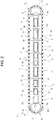
Figure 2 is a side view of one conveying device ofFigure 1 , with parts removed for clarity; -
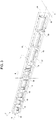
Figure 3 is a perspective view of a detail of the conveying device ofFigures 1 and2 , with parts removed for clarity; -
Figure 4 is an enlarged and partially sectionized perspective view of a portion of the detail ofFigure 3 , with parts removed for clarity; and -
Figure 5 is an enlarged perspective view of a further detail of the conveying device ofFigures 1 and2 , with parts removed for clarity. - Number 1 in
Figure 1 illustrates as a whole a conveying apparatus, in particular of a packaging machine, comprising one or more conveyingdevices 2, in particular one or more linearmotor conveying devices 2, even more particular one or more endless linearmotor conveying devices 2, in the specific case shown two. - According to a preferred non-limiting embodiment, the packaging machine is adapted to produce and/or handle and/or treat packages, such as bottles or containers. Preferentially but not necessarily, the packaging machine is configured to produce and/or to handle and/or to treat packages being filled with a pourable product.
- According to the specific non-limiting embodiment disclosed, the packaging machine is configured to apply closures onto the packages being filled with the pourable product, in particular during advancement of the packages along a package advancement path. In particular, the packaging machine is configured to apply closures onto the packages in the area (at) of a rupturable and/or pierceable zone of the packages.
- In alternative, packaging machine could be configured to form packages from a tube obtained from a web of packaging material.
- According to a further alternative not shown, packaging machine could be configured to execute any other treatment and/or handling.
- According to a preferred non-limiting embodiment, conveying apparatus 1 also comprises a
coupling structure 3 carryingconveying devices 2. In particular,coupling structure 3 is interposed between the twoconveying devices 2. - Preferentially but not necessarily, each one of conveying
devices 2 is mounted onto one respective lateral side ofcoupling structure 3. - With particular reference to
Figures 1 and2 , eachconveying device 2 comprises: - a plurality of
drive modules 4 arranged in succession of one another and at least partially defining atrack 5, in particular anendless track 5; - one or
more carts 6 being moveably engaged and/or being movably engageable ondrive modules 4 and/ortrack 5; and - a
support structure 7 supporting and/or carrying at leastdrive modules 4. - According to a preferred non-limiting embodiment, each
conveying device 2 also comprises one or moreauxiliary drive modules 8 coupled to therespective support structure 7. - Preferentially but not necessarily, each
drive module 4 defines a respective linear portion oftrack 5, and in particular eachauxiliary drive module 8 defines a respective curved portion oftrack 5. - According to a preferred non-limiting embodiment, conveying apparatus 1 comprises a control unit and/or each
conveying device 2 comprises a respective single control unit configured to control advancement of therespective carts 6 along therespective track 5 and along a respective advancement path P as defined by therespective track 5, in particular by controlling therespective drive modules 4 and/or the respectiveauxiliary drive modules 8. - Preferentially but not necessarily, advancement of the
respective carts 6 of eachconveying device 2 is controlled independently of the otherrespective carts 6. - It should be noted that independently controlled identifies the possibility to vary the advancement speeds and advancement accelerations and advancement decelerations of
carts 6 independently from theother carts 6 of therespective conveying device 2. This control is such that the relative distance betweensuccessive carts 6 may vary, but any (destructive) impact betweensuccessive carts 6 is avoided. - According to a preferred non-limiting embodiment, each
track 5 presents an endless configuration defining an endless advancement path P. - In particular, by providing for the
respective drive modules 4 andauxiliary drive modules 8 it is possible to define and/or obtain the endless configuration of therespective track 5. - According to a preferred non-limiting embodiment, advancement path P comprises linear portions P1 and curved portions P2. In particular,
drive modules 4 define the linear portions PI, and even more particularauxiliary drive modules 8 define the curved portions P2. - According to the specific embodiment disclosed,
drive modules 4 andauxiliary drive modules 8 are arranged such that the respective track 5 (and the respective advancement path P) present(s) a substantially oval shape. - According to a preferred non-limiting embodiment, each
drive module 4 and/or eachauxiliary drive module 8 is configured to selectively determine and/or generate, in use, a respective electromagnetic field for interaction with therespective carts 6, in particular with at least one respective interaction elements of therespective cart 6, for controlling advancement of therespective carts 6 along therespective track 5 and/or the respective advancement path P. - Preferentially but not necessarily and with particular reference to
Figures 1 ,2 and5 , eachdrive module 4 and/or eachauxiliary drive module 8 comprises at least onerespective housing 9 and at least one respective coil (not shown and known as such) arranged within therespective housing 9. In particular, each coil is configured to be selectively controlled so as to determine and/or define the respective electromagnetic field for interacting with the interaction elements of therespective carts 6. - According to a preferred non-limiting embodiment, the control unit and/or the single control units are configured to control (the respective)
drive modules 4 and/or (the respective)auxiliary drive modules 8, in particular the respective coils, for selectively controlling the respective electromagnetic fields. - According to a preferred non-limiting embodiment, each
drive module 4 and/or eachauxiliary drive module 8 also comprises further electronic components arranged within therespective housing 9. - Preferentially but not necessarily, each
housing 9 is realized (fully and/or at least partially) from and/or comprises a metallic material, such as e.g. aluminum. - According to a preferred non-limiting embodiment, each
housing 9 comprises an engagement surface - With particular reference to
Figures 1 and2 , eachdrive module 4 and/or eachauxiliary drive module 8, in particular therespective housing 9, comprises anengagement surface 10 being in contact withsupport structure 7. In particular,engagement surface 10 is arranged at a first end portion of therespective housing 9. - According to a preferred non-limiting embodiment, each
housing 9 also comprises acoupling section 11 configured to receive at least a portion of therespective carts 6 for guidingcarts 6. In particular, eachcoupling section 11 defines a second end portion of therespective housing 9 opposed to the respective first end portion. - According to a preferred non-limiting embodiment,
coupling sections 11 of therespective drive modules 4 and/orauxiliary drive modules 8 define and/or determine therespective track 5. - With particular reference to
Figures 1 to 4 , eachsupport structure 7 comprises acoupling surface 15, in particular being defined by outer surfaces ofsupport structure 7. - In particular, the respective engagement surfaces 10 of the
respective drive modules 4 and/orauxiliary drive modules 8, in particular therespective housings 9, are arranged in contact with a respective portion of therespective coupling surface 15. - Even more particular, each
housing 9 is fixed to therespective support structure 7 so that the respective engagement surfaces 10 are in contact with the respective portion of therespective coupling surface 15. - According to a preferred non-limiting embodiment, the
respective coupling surface 15 of eachsupport structure 7 is defined and/or determined by outer surfaces of therespective support structure 7. - According to a preferred non-limiting embodiment, each
support structure 7 extends along a respective longitudinal axis A, a first transversal axis B and a second transversal axis C, being perpendicular to one another. - According to the non-limiting embodiment disclosed, the extension of each
support structure 7 along the respective longitudinal axis A is larger than the extension along the respective first transversal axis B and the respective second transversal axis C. - In particular,
drive modules 4 are arranged onsupport structure 7 parallel to longitudinal axis A and/or linear portion P1 is parallel to longitudinal axis A. - In particular, each
auxiliary drive module 8 is arranged on therespective support structure 7 at a respective end face 16 of therespective support structure 7. - According to a preferred non-limiting embodiment, each
support structure 7 comprises twomain plates 17 being parallel to and spaced apart from one another, and in particular a plurality oftransversal plates 18 transversal tomain plates 17. - In particular,
main plates 16 extends parallel to longitudinal axis A. - In particular,
transversal plates 17 extend parallel to first transversal axis B. - According to a preferred non-limiting embodiment, at least two respective
transversal plates 18 define and/or carry the respective end faces 16 of therespective support structure 7. - Preferentially but not necessarily, the respective
main plates 17 of eachsupport structure 7 extend between the respectivetransversal plates 18 defining and/or carrying the respective end faces 16. - According to a preferred non-limiting embodiment, outer surfaces of the respective
main plates 17 and the respectivetransversal plates 18 defining and/or carrying the respective end faces 16 define therespective coupling surface 15 of therespective support structure 7. - According to a preferred non-limiting embodiment, each
drive module 4 is mounted to one respectivemain plate 17, and in particular eachauxiliary drive module 8 is mounted to at least one respectivetransversal plate 18. - According to a preferred non-limiting embodiment, each
support structure 7 is connected to thecoupling structure 3, in particular at the respective lateral side ofcoupling structure 3, for connecting the respective conveyingdevice 2 tocoupling structure 3. - Advantageously, each conveying
device 2 comprises cooling means 19 for cooling therespective support structure 7 so as to cool at least therespective drive modules 4. - It should be noted that
drive modules 4, in particular the respective coil and/or the respective electronic components, generate, in use, heat, which needs to be removed fromdrive modules 4 so as to avoid any overheating. According to the present invention this is achieved by cooling therespective support structure 7, which then removes the created energy (the heat) from therespective drive modules 4. - According to a preferred non-limiting embodiment, each cooling means 19 is configured to cool at least portions of the
respective support structure 7 by means of a cooling fluid, such as cooled water. In particular, with respect to the present invention, a cooling fluid has a temperature, which allows heat produced by the coils and/or the electronic components to be removed. - Preferentially but not necessarily, cooling means 19 comprise a supply unit for conditioning and/or providing the cooling fluid.
- According to a possible non-limiting embodiment, conveying apparatus 1 comprises a single supply unit for providing the cooling fluid to the respective cooling means 19 of the conveying
devices 2. - According to a preferred non-limiting embodiment, each cooling means 19 comprises at least one flow conduit for the cooling fluid, the flow conduit being coupled to the
respective support structure 7. - According to a possible non-limiting embodiment not shown, the flow conduits are at least partially formed by tubes attached and/or coupled to the
respective support structure 7. - According to a preferred non-limiting embodiment, each
support structure 7 comprises at least oneinternal flow conduit 20 for the cooling fluid, in particular theinternal flow conduit 20 defining and/or determining the respective flow conduits. In particular, theinternal flow conduit 20 extending withinsupport structure 7 along its entire extension. - In particular, in this manner, it is possible to introduce the cooling fluid into the
respective support structure 7, which, in use, circulates therein and cools (i.e. removes the heat generated by the coils and/or the electronic components)support structure 7. - According to a preferred non-limiting embodiment, each
internal flow conduit 20 comprises at least aninlet opening 21 and at least anoutlet opening 22, in particular inlet opening 21 and outlet opening 22 being in fluid connection with the respective supply unit, even more particular by means of respective tubes of the respective cooling means 19 and/or the respective supply unit. In particular, eachinternal flow conduit 20 defines together with the respective supply unit (and the respective tubes) a closed circuit allowing for the flow of the cooling fluid. - With particular reference to
Figure 4 , eachinternal flow conduit 20 comprisesmain conduit portions 23 being arranged at and/or directly below respective portions of therespective coupling surface 15 of therespective support structure 7. In this manner, at least portions ofcoupling surface 15 become cooled (i.e. heat is removed). In particular, this guarantees in an efficient manner that the heat generated and/or created at least by therespective drive modules 4 is removed as the generated and/or created heat is transfer by means of the contact between the respective engagement surfaces 10 onto the respective portions of therespective coupling surface 15. - According to a preferred non-limiting embodiment,
main conduit portions 23 are arranged within respectivemain plates 17. - According to a preferred non-limiting embodiment, each
internal flow conduit 20 also comprises connectingconduit portions 24 fluidically connecting the respectivemain conduit portions 23 with one another. In particular, connectingconduit portions 24 are provided within the respectivetransversal plates 18. - With particular reference to
Figure 1 , each cooling means 19 comprises coolingplates 25 laterally mounted on respectiveauxiliary drive modules 8 and configured to receive a cooling fluid, in particular from the respective supply unit, for cooling the respectiveauxiliary drive modules 8. This allows to improve the cooling (i.e. the removal of the heat generated by the respective coils and/or electronic components of the respective auxiliary drive modules 8) of the respectiveauxiliary drive modules 8. - According to a preferred non-limiting embodiment, each
support structure 7 is realized (at least partially) from and/or comprises a respective material. In particular, the material ofsupport structure 7 is similar and/or the same as the material ofhousings 9. E.g. also, eachsupport structure 7 is realized from aluminum. It should be noted that similar means that e.g. eachsupport structure 7 is realized from a respective metal or alloy andhousings 7 are also made from this kind of metal or alloy, but the specific treatments for obtaining the respective material or the respective compositions may differ. - The use of the same or a similar material is advantageous, as this guarantees that each
support structure 7 andhousings 9 present similar or the same thermal behavior as expressed by the substantially same thermal expansion coefficient. This avoids the creation of surface tensions between eachsupport structure 7 and therespective housings 9 due to changes of the temperatures. - According to an alternative non-limiting embodiment, the material of each
support structure 7 and of eachhousing 9 have a similar or a substantially similar thermal expansion coefficient, in particular for avoiding the creation of surface tensions between eachsupport structure 7 and therespective housings 9 due to changes of the temperatures. - According to a preferred non-limiting embodiment, each conveying
device 2 further comprises a compensation layer, in particular a deformable compensation layer, even more particular an elastically deformable compensation layer, arranged between therespective coupling surface 15 and the respective engagement surfaces 10. In particular, the compensation layer is configured to compensate for differences in the surface roughness of therespective coupling surface 15 and the respective engagement surfaces 10. - It should be noted that the
respective coupling surface 15 and the respective engagement surfaces 10 present respective surface roughness on the microscopic scale, which also defines and/or determines an effective contact area between therespective coupling surface 15 and the respective engagement surfaces 10. Any changes in the local temperatures may result in the occurrence of unwanted surface tensions. By providing for the compensation layer, the occurrence of these surface tensions is further reduced. - According to a preferred non-limiting embodiment, each compensation layer presents a thickness in the millimeter-range (i.e. a few millimeters).
- According to the specific non-limiting embodiment shown, conveying apparatus 1 is designed such that one
cart 4 of each conveyingdevice 2 is coupled to onerespective cart 4 of the other conveying device 2 (defining a respective pair of carts 6) . In particular, each pair ofcarts 6 is coupled to one another by means of acoupling mechanism 26. - According to a preferred non-limiting embodiment, at least one of the
carts 6 of each pair ofcarts 6 comprises at least oneoperative assembly 27 configured to handle and/or treat at least one package. In the specific non-limiting case shown, eachoperative assembly 27 is configured to receive and to retain a closure or a closure assembly and to apply the closure or closure assembly onto one respective package (the package advancing along the package advancement path). - Preferentially but not necessarily, operation of each
operative assembly 27 is controlled by means of a control of the relative position and/or the relative velocity and/or the relative acceleration between therespective carts 6 of the respective pair ofcarts 6. In particular, therespective coupling mechanism 26 is coupled to the respectiveoperative assembly 27 and is configured such to modify its specific configuration in dependence of the relative position and/or the relative velocity and/or the relative acceleration between therespective carts 6 of the respective pair ofcarts 6 for controlling operation of the respectiveoperative assembly 27. - In use, the packaging machine handles and/or treats and/or produces the packages filled with the pourable product.
- In particular, the handling and/or treatment and/or production of the packages is executed by means of
operative assemblies 27. - Even more particular, operation of
operative assemblies 27 is controlled by means a control of the advancement of therespective carts 6 of the respective pair ofcarts 6 along the respective advancement paths P and/ortracks 5, in particular by means of controlling the relative position and/or the relative velocity and/or the relative acceleration between therespective carts 6 of the respective pair ofcarts 6. - According to a preferred non-limiting embodiment,
carts 6 of each conveyingdevice 2 advance along therespective track 5 and/or advancement path P. In particular, advancement of eachcart 6 is controlled (by the control unit and/or the respective single control unit) by means of a selective control of the respective coils of therespective drive modules 4 and/orauxiliary drive modules 8. - Advantageously, during operation of each conveying
device 2 therespective support structure 7 is cooled by means of the respective cooling means 19 for cooling at least therespective drive modules 4. - Preferentially but not necessarily, each
support structure 7 is cooled by means of a flow of the cooling fluid, in particular flowing within therespective support structure 7. - Preferentially but not necessarily, the flow of the cooling fluid occurs within the respective
internal flow conduits 20. In particular, the respective supply unit introduces and extracts the cooling fluid into and from the respectiveinternal flow conduit 20 through respectively the corresponding inlet opening 21 andoutlet opening 22. - Preferentially but not necessarily,
auxiliary drive modules 8 are also cooled by means of therespective cooling plates 25. - The advantages of conveying
devices 2 according to the present invention will be clear from the foregoing description. - In particular, the cooling of at least drive
units 4 is achieved in an easy manner by cooling therespective support structures 7 and coming along with a simple design. - A further advantage resides in providing for the
internal flow conduits 20, which allows to maximize the cooling effect. - An even other advantage is seen in that it is possible to remove
drive modules 4 without the need to dismount portions of the cooling means 19. - A further advantage resides in that the
internal flow conduits 20 can be easily put into fluid connection with the supply unit by means of respective tubes, which can be easily and cleanly dismounted. - An even further advantage resides in that the
support structure 7 andhousings 9 are of a similar or the same material and/or have a similar thermal behavior, thereby avoiding the formation of any tensions and deformations. - Clearly, changes may be made to conveying apparatus 1 and/or or conveying
devices 2 as described herein without, however, departing from the scope of protection as defined in the accompanying claims.
Claims (15)
- A conveying device (2) comprising:- a plurality of drive modules (4) arranged in succession of one another and at least partially defining a track (5);- at least one cart (6) being moveably engaged and/or engageable to the drive modules (4) and/or the track (5);- a support structure (7) supporting and/or carrying the drive modules (4); and- cooling means (19) coupled to the support structure and configured to cool the support structure (7) for cooling the drive modules (4).
- Conveying device according to claim 1, wherein the cooling means (19) are configured to cool the support structure (7) by means of a cooling fluid.
- Conveying device according to claim 1 or 2, wherein the cooling means (19) comprise at least one flow conduit (20) for the cooling fluid;
wherein the flow conduit (20) is coupled to the support structure (7) and/or the support structure (7) comprises the flow conduit (7). - Conveying device according to any one of the preceding claims, wherein the support structure (7) comprises at least one internal flow conduit (20) for the cooling fluid.
- Conveying device according to claim 4, wherein the internal flow conduit (20) comprises at least an inlet opening (21) and at least an outlet opening (22) arranged at an outer surface of the support structure (7) .
- Conveying device according to claim 4 or 5, wherein the support structure (7) comprises a coupling surface (15) and each drive module (4) comprises an engagement surface (10) arranged in contact with a respective portion of the coupling surface (15);
wherein the internal flow conduit (20) comprises conduit portions (23) being arranged at the coupling surface (15) of the support structure (7), so as to cool the coupling surface (15) for cooling the drive modules (4) . - Conveying device according to any one of the preceding claims, wherein each drive module (4) comprises at least:- a housing (9); and- one coil arranged within the housing (9) and configured to selectively generate an electromagnetic field for controlling advancement of the cart (4) along the track (5) ;wherein the support structure (7) is made from a first material and the housings (9) of the drive modules (4) are made from a second material;
wherein the first material and the second material are the same or similar and/or the thermal expansion coefficient of the first material and the second material are substantially identical. - Conveying device according to any one of the preceding claims, wherein the support structure (7) comprises a coupling surface (15) and each drive module (4) comprises an engagement surface (10) placed onto a respective portion of the coupling surface (15);
the conveying device (2) further comprises a compensation layer arranged between the coupling surface (15) and the engagement surfaces (10);
wherein the compensation layer is configured to compensate for differences in the surface roughness of the coupling surface (15) and the engagement surfaces (10) . - Conveying device according to any one of the preceding claims, further comprising one or more auxiliary drive modules (8) for defining curved portions of the track (5);
wherein the drive modules (4) define linear portions of the track (5);
wherein the cooling means (19) comprise cooling plates (25) laterally mounted on the auxiliary drive modules (8) and configured to receive a cooling fluid for cooling the auxiliary drive modules (8). - Packaging machine for the treatment and/or handling of packages, in particular packages filled with a pourable product, comprising at least one conveying device (2) according to any one of the preceding claims.
- Packaging machine according to claim 10, comprising at least a further conveying device (2) parallel to the conveying device (2).
- Packaging machine according to claim 11, wherein each cart (6) of the conveying device (2) is coupled to one respective cart (6) of the further conveying device (2);
wherein at least the cart (6) of the conveying device (2) comprises at least an operative assembly (27) configured to handle and/or treat at least one package. - Packaging machine according to claim 12, wherein operation of the operative assembly (27) is controlled by means of a control of the relative position and/or the relative velocity and/or the relative acceleration between the respective cart (6) of the conveying device (2) and the respective cart (6) of the further conveying device (2).
- Method of cooling a conveying device (2) according to any one of claims 1 to 9, comprising the step of cooling the support structure (7) for cooling the drive modules (4).
- Method according to claim 14, wherein a cooling fluid circulates within the support structure (7) for removing heat from the drive modules (4).
Priority Applications (1)
| Application Number | Priority Date | Filing Date | Title |
|---|---|---|---|
| EP19175424.1A EP3741717A1 (en) | 2019-05-20 | 2019-05-20 | Conveying device, packaging machine having such a conveying device and method of cooling such a conveying device |
Applications Claiming Priority (1)
| Application Number | Priority Date | Filing Date | Title |
|---|---|---|---|
| EP19175424.1A EP3741717A1 (en) | 2019-05-20 | 2019-05-20 | Conveying device, packaging machine having such a conveying device and method of cooling such a conveying device |
Publications (1)
| Publication Number | Publication Date |
|---|---|
| EP3741717A1 true EP3741717A1 (en) | 2020-11-25 |
Family
ID=66625781
Family Applications (1)
| Application Number | Title | Priority Date | Filing Date |
|---|---|---|---|
| EP19175424.1A Withdrawn EP3741717A1 (en) | 2019-05-20 | 2019-05-20 | Conveying device, packaging machine having such a conveying device and method of cooling such a conveying device |
Country Status (1)
| Country | Link |
|---|---|
| EP (1) | EP3741717A1 (en) |
Cited By (3)
| Publication number | Priority date | Publication date | Assignee | Title |
|---|---|---|---|---|
| WO2023154637A1 (en) * | 2022-02-11 | 2023-08-17 | The Procter & Gamble Company | High speed telescopic fitting of a tray and hood |
| CN118342318A (en) * | 2024-06-20 | 2024-07-16 | 河南威猛振动设备股份有限公司 | Vibrating motor end cover support processing production line |
| EP4550639A1 (en) * | 2023-10-31 | 2025-05-07 | Rockwell Automation Technologies, Inc. | Support and heatsink for an independent cart system |
Citations (9)
| Publication number | Priority date | Publication date | Assignee | Title |
|---|---|---|---|---|
| US5051225A (en) * | 1988-06-22 | 1991-09-24 | E. I. Du Pont De Nemours And Company | Method of drawing plastic film in a tenter frame |
| US20130069449A1 (en) * | 2011-09-15 | 2013-03-21 | Nikon Corporation | Modular coil arrays for planar and linear motors |
| WO2013083757A2 (en) * | 2011-12-08 | 2013-06-13 | Max Bögl Bauunternehmung GmbH & Co. KG | Drive apparatus for a magnetic levitation transport system |
| US20140103748A1 (en) * | 2012-10-11 | 2014-04-17 | Hiwin Mikrosystem Corp. | Linear motor air-cooling structure |
| DE202012013152U1 (en) * | 2012-03-27 | 2015-02-11 | Beckhoff Automation Gmbh | Stator device for a linear motor and linear transport system |
| US20160164392A1 (en) * | 2014-12-08 | 2016-06-09 | Hon Hai Precision Industry Co., Ltd. | Linear motor |
| US20170259527A1 (en) * | 2013-07-10 | 2017-09-14 | Lumentum Operations Llc | Assembly of components having different coefficients of thermal expansion |
| EP3324521A1 (en) * | 2016-11-16 | 2018-05-23 | Etel S. A.. | Cooling plate for a linear motor |
| DE102016122612A1 (en) * | 2016-11-23 | 2018-05-24 | Kessler energy GmbH | Motor component, primary part and linear motor |
-
2019
- 2019-05-20 EP EP19175424.1A patent/EP3741717A1/en not_active Withdrawn
Patent Citations (9)
| Publication number | Priority date | Publication date | Assignee | Title |
|---|---|---|---|---|
| US5051225A (en) * | 1988-06-22 | 1991-09-24 | E. I. Du Pont De Nemours And Company | Method of drawing plastic film in a tenter frame |
| US20130069449A1 (en) * | 2011-09-15 | 2013-03-21 | Nikon Corporation | Modular coil arrays for planar and linear motors |
| WO2013083757A2 (en) * | 2011-12-08 | 2013-06-13 | Max Bögl Bauunternehmung GmbH & Co. KG | Drive apparatus for a magnetic levitation transport system |
| DE202012013152U1 (en) * | 2012-03-27 | 2015-02-11 | Beckhoff Automation Gmbh | Stator device for a linear motor and linear transport system |
| US20140103748A1 (en) * | 2012-10-11 | 2014-04-17 | Hiwin Mikrosystem Corp. | Linear motor air-cooling structure |
| US20170259527A1 (en) * | 2013-07-10 | 2017-09-14 | Lumentum Operations Llc | Assembly of components having different coefficients of thermal expansion |
| US20160164392A1 (en) * | 2014-12-08 | 2016-06-09 | Hon Hai Precision Industry Co., Ltd. | Linear motor |
| EP3324521A1 (en) * | 2016-11-16 | 2018-05-23 | Etel S. A.. | Cooling plate for a linear motor |
| DE102016122612A1 (en) * | 2016-11-23 | 2018-05-24 | Kessler energy GmbH | Motor component, primary part and linear motor |
Non-Patent Citations (1)
| Title |
|---|
| BECKHOFF: "Benefit from intelligent drive technology. XTS. The extended Transport System", 30 September 2015 (2015-09-30), Beckhoff.com, XP055477367, Retrieved from the Internet <URL:https://download.beckhoff.com/download/Document/catalog/XTS_Beckhoff_e.pdf> [retrieved on 20180522] * |
Cited By (7)
| Publication number | Priority date | Publication date | Assignee | Title |
|---|---|---|---|---|
| WO2023154637A1 (en) * | 2022-02-11 | 2023-08-17 | The Procter & Gamble Company | High speed telescopic fitting of a tray and hood |
| EP4242121A1 (en) * | 2022-02-11 | 2023-09-13 | The Procter & Gamble Company | High speed telescopic fitting of a tray and hood |
| CN118103296A (en) * | 2022-02-11 | 2024-05-28 | 宝洁公司 | High-speed assembly of boxes and covers |
| US12103727B2 (en) | 2022-02-11 | 2024-10-01 | The Procter & Gamble Company | High speed telescopic fitting of a tray and hood |
| JP2024536311A (en) * | 2022-02-11 | 2024-10-04 | ザ プロクター アンド ギャンブル カンパニー | High speed nesting of tray and hood |
| EP4550639A1 (en) * | 2023-10-31 | 2025-05-07 | Rockwell Automation Technologies, Inc. | Support and heatsink for an independent cart system |
| CN118342318A (en) * | 2024-06-20 | 2024-07-16 | 河南威猛振动设备股份有限公司 | Vibrating motor end cover support processing production line |
Similar Documents
| Publication | Publication Date | Title |
|---|---|---|
| CN102308008B (en) | Heat treatment device and heat treatment method | |
| WO2010005083A1 (en) | Heat treatment apparatus | |
| KR20090010181A (en) | Method and apparatus for heat treatment, in particular for connection by soldering | |
| JP4827959B2 (en) | Machine tool feed shaft cooling system | |
| CN103237917B (en) | Dry method coating unit | |
| PL137713B1 (en) | Apparatus for centrally aligning thin webs while introducing them to a winding machine | |
| CN1950535B (en) | Thermal vacuum deposition method and apparatus | |
| JP5584526B2 (en) | Electromagnetic damping device for molten metal plating equipment | |
| CN107257865A (en) | For carrying out deformation heat treatment method, furnace apparatus and system to workpiece | |
| US20110017016A1 (en) | System and method for cooling and removing iron from a hearth | |
| WO2017043137A1 (en) | Heat treatment apparatus | |
| KR102957789B1 (en) | Transport apparatus | |
| WO2017104076A1 (en) | Cooling method and device for forging valve | |
| JP2001300753A (en) | Laser cutting method for steel material and apparatus therefor | |
| CN100436637C (en) | Apparatus for hot-dip coating of metal strips | |
| JP4495553B2 (en) | Steel sheet fluttering suppression method | |
| JP2958236B2 (en) | Hot plate cooling device | |
| CN117004810B (en) | A shaft cooling structure and a shaft laser cladding device | |
| US20150252693A1 (en) | Condenser | |
| JP2021098221A (en) | Mold, and molding device | |
| JP2012055964A (en) | Hot processing device of metal tube | |
| JPH0143263Y2 (en) | ||
| WO2006124102A2 (en) | Coolant system for inject cores | |
| CN102179509A (en) | Cooling and protective device for stopper rod mechanism of continuous casting machine | |
| JP2004027274A (en) | Cooling method in welded stress removing apparatus and its device |
Legal Events
| Date | Code | Title | Description |
|---|---|---|---|
| PUAI | Public reference made under article 153(3) epc to a published international application that has entered the european phase |
Free format text: ORIGINAL CODE: 0009012 |
|
| STAA | Information on the status of an ep patent application or granted ep patent |
Free format text: STATUS: THE APPLICATION HAS BEEN PUBLISHED |
|
| AK | Designated contracting states |
Kind code of ref document: A1 Designated state(s): AL AT BE BG CH CY CZ DE DK EE ES FI FR GB GR HR HU IE IS IT LI LT LU LV MC MK MT NL NO PL PT RO RS SE SI SK SM TR |
|
| AX | Request for extension of the european patent |
Extension state: BA ME |
|
| STAA | Information on the status of an ep patent application or granted ep patent |
Free format text: STATUS: THE APPLICATION IS DEEMED TO BE WITHDRAWN |
|
| 18D | Application deemed to be withdrawn |
Effective date: 20210526 |