EP3741670A2 - Multi-rotor rotorcraft - Google Patents
Multi-rotor rotorcraft Download PDFInfo
- Publication number
- EP3741670A2 EP3741670A2 EP20172614.8A EP20172614A EP3741670A2 EP 3741670 A2 EP3741670 A2 EP 3741670A2 EP 20172614 A EP20172614 A EP 20172614A EP 3741670 A2 EP3741670 A2 EP 3741670A2
- Authority
- EP
- European Patent Office
- Prior art keywords
- rotor
- pair
- rotorcraft
- fuselage
- rotor assemblies
- Prior art date
- Legal status (The legal status is an assumption and is not a legal conclusion. Google has not performed a legal analysis and makes no representation as to the accuracy of the status listed.)
- Granted
Links
Images






Classifications
-
- B—PERFORMING OPERATIONS; TRANSPORTING
- B64—AIRCRAFT; AVIATION; COSMONAUTICS
- B64C—AEROPLANES; HELICOPTERS
- B64C1/00—Fuselages; Constructional features common to fuselages, wings, stabilising surfaces or the like
- B64C1/22—Other structures integral with fuselages to facilitate loading, e.g. cargo bays, cranes
-
- B—PERFORMING OPERATIONS; TRANSPORTING
- B64—AIRCRAFT; AVIATION; COSMONAUTICS
- B64C—AEROPLANES; HELICOPTERS
- B64C29/00—Aircraft capable of landing or taking-off vertically, e.g. vertical take-off and landing [VTOL] aircraft
- B64C29/0008—Aircraft capable of landing or taking-off vertically, e.g. vertical take-off and landing [VTOL] aircraft having its flight directional axis horizontal when grounded
- B64C29/0016—Aircraft capable of landing or taking-off vertically, e.g. vertical take-off and landing [VTOL] aircraft having its flight directional axis horizontal when grounded the lift during taking-off being created by free or ducted propellers or by blowers
- B64C29/0025—Aircraft capable of landing or taking-off vertically, e.g. vertical take-off and landing [VTOL] aircraft having its flight directional axis horizontal when grounded the lift during taking-off being created by free or ducted propellers or by blowers the propellers being fixed relative to the fuselage
-
- B—PERFORMING OPERATIONS; TRANSPORTING
- B64—AIRCRAFT; AVIATION; COSMONAUTICS
- B64C—AEROPLANES; HELICOPTERS
- B64C11/00—Propellers, e.g. of ducted type; Features common to propellers and rotors for rotorcraft
- B64C11/001—Shrouded propellers
-
- B—PERFORMING OPERATIONS; TRANSPORTING
- B64—AIRCRAFT; AVIATION; COSMONAUTICS
- B64C—AEROPLANES; HELICOPTERS
- B64C27/00—Rotorcraft; Rotors peculiar thereto
- B64C27/006—Safety devices
-
- B—PERFORMING OPERATIONS; TRANSPORTING
- B64—AIRCRAFT; AVIATION; COSMONAUTICS
- B64D—EQUIPMENT FOR FITTING IN OR TO AIRCRAFT; FLIGHT SUITS; PARACHUTES; ARRANGEMENT OR MOUNTING OF POWER PLANTS OR PROPULSION TRANSMISSIONS IN AIRCRAFT
- B64D45/00—Aircraft indicators or protectors not otherwise provided for
- B64D45/0005—Devices specially adapted to indicate the position of a movable element of the aircraft, e.g. landing gear
-
- B—PERFORMING OPERATIONS; TRANSPORTING
- B64—AIRCRAFT; AVIATION; COSMONAUTICS
- B64U—UNMANNED AERIAL VEHICLES [UAV]; EQUIPMENT THEREFOR
- B64U10/00—Type of UAV
- B64U10/10—Rotorcrafts
- B64U10/13—Flying platforms
- B64U10/16—Flying platforms with five or more distinct rotor axes, e.g. octocopters
-
- B—PERFORMING OPERATIONS; TRANSPORTING
- B64—AIRCRAFT; AVIATION; COSMONAUTICS
- B64U—UNMANNED AERIAL VEHICLES [UAV]; EQUIPMENT THEREFOR
- B64U30/00—Means for producing lift; Empennages; Arrangements thereof
- B64U30/10—Wings
-
- B—PERFORMING OPERATIONS; TRANSPORTING
- B64—AIRCRAFT; AVIATION; COSMONAUTICS
- B64U—UNMANNED AERIAL VEHICLES [UAV]; EQUIPMENT THEREFOR
- B64U30/00—Means for producing lift; Empennages; Arrangements thereof
- B64U30/20—Rotors; Rotor supports
- B64U30/24—Coaxial rotors
-
- B—PERFORMING OPERATIONS; TRANSPORTING
- B64—AIRCRAFT; AVIATION; COSMONAUTICS
- B64U—UNMANNED AERIAL VEHICLES [UAV]; EQUIPMENT THEREFOR
- B64U30/00—Means for producing lift; Empennages; Arrangements thereof
- B64U30/20—Rotors; Rotor supports
- B64U30/29—Constructional aspects of rotors or rotor supports; Arrangements thereof
- B64U30/295—Rotors arranged in the wings
-
- B—PERFORMING OPERATIONS; TRANSPORTING
- B64—AIRCRAFT; AVIATION; COSMONAUTICS
- B64U—UNMANNED AERIAL VEHICLES [UAV]; EQUIPMENT THEREFOR
- B64U30/00—Means for producing lift; Empennages; Arrangements thereof
- B64U30/20—Rotors; Rotor supports
- B64U30/29—Constructional aspects of rotors or rotor supports; Arrangements thereof
- B64U30/299—Rotor guards
-
- B—PERFORMING OPERATIONS; TRANSPORTING
- B64—AIRCRAFT; AVIATION; COSMONAUTICS
- B64C—AEROPLANES; HELICOPTERS
- B64C1/00—Fuselages; Constructional features common to fuselages, wings, stabilising surfaces or the like
- B64C1/14—Windows; Doors; Hatch covers or access panels; Surrounding frame structures; Canopies; Windscreens accessories therefor, e.g. pressure sensors, water deflectors, hinges, seals, handles, latches, windscreen wipers
- B64C1/1407—Doors; surrounding frames
- B64C1/1415—Cargo doors, e.g. incorporating ramps
-
- B—PERFORMING OPERATIONS; TRANSPORTING
- B64—AIRCRAFT; AVIATION; COSMONAUTICS
- B64C—AEROPLANES; HELICOPTERS
- B64C1/00—Fuselages; Constructional features common to fuselages, wings, stabilising surfaces or the like
- B64C1/14—Windows; Doors; Hatch covers or access panels; Surrounding frame structures; Canopies; Windscreens accessories therefor, e.g. pressure sensors, water deflectors, hinges, seals, handles, latches, windscreen wipers
- B64C1/1407—Doors; surrounding frames
- B64C1/1423—Passenger doors
-
- B—PERFORMING OPERATIONS; TRANSPORTING
- B64—AIRCRAFT; AVIATION; COSMONAUTICS
- B64C—AEROPLANES; HELICOPTERS
- B64C15/00—Attitude, flight direction, or altitude control by jet reaction
- B64C15/02—Attitude, flight direction, or altitude control by jet reaction the jets being propulsion jets
-
- B—PERFORMING OPERATIONS; TRANSPORTING
- B64—AIRCRAFT; AVIATION; COSMONAUTICS
- B64C—AEROPLANES; HELICOPTERS
- B64C27/00—Rotorcraft; Rotors peculiar thereto
- B64C27/22—Compound rotorcraft, i.e. aircraft using in flight the features of both aeroplane and rotorcraft
- B64C27/26—Compound rotorcraft, i.e. aircraft using in flight the features of both aeroplane and rotorcraft characterised by provision of fixed wings
-
- B—PERFORMING OPERATIONS; TRANSPORTING
- B64—AIRCRAFT; AVIATION; COSMONAUTICS
- B64U—UNMANNED AERIAL VEHICLES [UAV]; EQUIPMENT THEREFOR
- B64U2101/00—UAVs specially adapted for particular uses or applications
- B64U2101/60—UAVs specially adapted for particular uses or applications for transporting passengers; for transporting goods other than weapons
-
- B—PERFORMING OPERATIONS; TRANSPORTING
- B64—AIRCRAFT; AVIATION; COSMONAUTICS
- B64U—UNMANNED AERIAL VEHICLES [UAV]; EQUIPMENT THEREFOR
- B64U2101/00—UAVs specially adapted for particular uses or applications
- B64U2101/60—UAVs specially adapted for particular uses or applications for transporting passengers; for transporting goods other than weapons
- B64U2101/61—UAVs specially adapted for particular uses or applications for transporting passengers; for transporting goods other than weapons for transporting passengers
-
- B—PERFORMING OPERATIONS; TRANSPORTING
- B64—AIRCRAFT; AVIATION; COSMONAUTICS
- B64U—UNMANNED AERIAL VEHICLES [UAV]; EQUIPMENT THEREFOR
- B64U50/00—Propulsion; Power supply
- B64U50/10—Propulsion
- B64U50/13—Propulsion using external fans or propellers
- B64U50/14—Propulsion using external fans or propellers ducted or shrouded
-
- B—PERFORMING OPERATIONS; TRANSPORTING
- B64—AIRCRAFT; AVIATION; COSMONAUTICS
- B64U—UNMANNED AERIAL VEHICLES [UAV]; EQUIPMENT THEREFOR
- B64U60/00—Undercarriages
Definitions
- the present disclosure relates to multi-rotor rotorcraft.
- Multi-rotor rotorcraft including autonomous rotorcraft, are increasingly being developed for transporting cargo and human passengers.
- Such rotorcraft have different design considerations than traditional helicopters and recreational autonomous rotorcraft, including weight considerations, safety considerations, considerations associated with loading and unloading cargo and/or human passengers to and from a rotorcraft, and other considerations.
- Multi-rotor rotorcraft and methods of assembling a multi-rotor rotorcraft comprise a fuselage and at least four rotor assemblies that are operatively supported by and spaced-around the fuselage. Each of the at least four rotor assemblies defines a spin volume and a spin diameter.
- Some multi-rotor rotorcraft further comprise at least one rotor guard that is fixed relative to the fuselage, that borders the spin volume of at least one of the at least four rotor assemblies, and that is configured to provide a visual indication of and safety barrier to the spin volume of the at least one of the at least four rotor assemblies.
- Various configurations of rotor guards are disclosed.
- Multi-rotor rotorcraft are disclosed herein.
- elements that are likely to be included in a given example are illustrated in solid lines, while elements that are optional to a given example are illustrated in broken lines.
- elements that are illustrated in solid lines are not essential to all examples of the present disclosure, and an element shown in solid lines may be omitted from a particular example without departing from the scope of the present disclosure.
- elements that are illustrated in broken lines may be important to some examples of the present disclosure.
- multi-rotor rotorcraft 10 which may be referred to herein simply as rotorcraft 10 or as a multi-rotor vehicle 10, comprise a fuselage 12 and at least four rotor assemblies 14 that are operatively supported by and spaced-around the fuselage 12.
- Each of the at least four rotor assemblies 14 defines a spin volume 24 and a spin diameter 26.
- spin volume is an imaginary cylindrical volume defined by the outer most extent of a rotor assembly's rotors when spinning.
- spin diameter is the diameter of a corresponding spin volume.
- Some rotorcraft 10 may be unmanned and/or autonomous and therefore may be described as autonomous rotorcraft. Additionally or alternatively, some rotorcraft 10 may be pilot operated or at least configured to be pilot operated. In some such examples, the pilot may be onboard the rotorcraft 10, and thus the rotorcraft may be described as a manned rotorcraft. In some examples, rotorcraft 10 may be configured to be piloted remotely and therefore may be described as a remote-controlled rotorcraft. Rotorcraft 10 may be used to transport a payload, such as cargo or human passengers.
- the fuselage 12 comprises an internal compartment 16 and an access door 18 that has a door-width 22.
- the access door 18 provides selective access to the internal compartment 16.
- Some examples of rotorcraft 10 include more than one access door 18 as optionally and schematically illustrated in Fig. 1 .
- Various configurations of access doors 18 may be incorporated into a rotorcraft 10, including access doors that are hinged or otherwise pivot between a closed configuration and a fully open configuration.
- the access door 18 has more than one section, such as an upper section 62 and a lower section 64 that are configured to collectively provide selective access to the internal compartment 16.
- the lower section 64 when the access door 18 is in the fully open configuration, the lower section 64 is at or below the level of a floor 66 if the internal compartment 16, when the rotorcraft 10 is operatively positioned on a horizontal ground surface. Accordingly, a payload may be easily loaded into and unloaded from the internal compartment 16 when the access door 18 is in the fully open configuration, for example from an adjacent loading structure, such as a wheeled cart.
- the lower section 64 may serve as a ramp from the ground surface or other loading structure to the floor 66 of the internal compartment 16.
- the access door 18 may only include a single section that translates and/or pivots upward to provide selective access to the internal compartment 16.
- the access door 18 may only include a single section that translates and/or pivots downward to provide selective access to the internal compartment 16.
- the internal compartment 16 has a volume of at least 0.5 cubic meters (m 3 ), of at least 1 m 3 , of at least 1.5 m 3 , of at least 2 m 3 , of between 0.5 m 3 and 3 m 3 , and/or at most 3 m 3 .
- the at least four rotor assemblies 14 comprise a first pair 20 of rotor assemblies 14 positioned on opposing sides of the access door 18, and a spacing 28 between the spin volumes 24 of the first pair 20 of rotor assemblies 14 is at least 70%, at least 80%, at least 90%, at least 100%, at least 110%, or at least 120% of the door-width 22. In some applications, having the spacing 28 at least 100% of the door-width is important.
- a rectangular prismatic volume of space extending from the access door 18 away from the fuselage may be substantially void or completely void of structure of the rotorcraft 10, including the rotor assemblies 14 and related hardware, such as optional rotor guards 50 discussed herein.
- the loading and unloading of payload to and from the internal compartment 16 may be safely accomplished.
- the internal compartment 16 is sized to selectively receive cargo
- the access door 18 is sized to permit loading and unloading of cargo into and from the internal compartment 16.
- Such rotorcraft 10 may be described as cargo aircraft.
- the internal compartment 16 is configured for transportation of at least one human passenger, and the access door 18 is sized for entry and exit of the at least one human passenger to and from the internal compartment 16.
- Such rotorcraft 10 may be described as passenger aircraft.
- the at least four rotor assemblies 14 comprise a first pair 20 of rotor assemblies positioned on opposing lateral sides of the fuselage 12, and the rotorcraft 10 further comprises a first pair 30 of elongate support arms 32.
- Elongate support arms 32 additionally or alternatively may be described as support beams or booms.
- Each elongate support arm 32 interconnects a respective one of the first pair 20 of rotor assemblies 14 to the fuselage 12.
- the lengths of the elongate support arms 32, and thus the location of the respective rotor assemblies 14 relative to the fuselage 12, may be optimized for maneuverability and stability of the rotorcraft 10, as well as for the spacing 28 discussed above.
- each elongate support arm 32 of the first pair 30 of elongate support arms 32 extends along a respective curved path between the fuselage 12 and the respective one of the first pair 20 of rotor assemblies 14.
- each respective curved path is concave away from the fuselage 12.
- elongate support arms 32 whose respective curved paths are convex away from the fuselage 12, as well as elongate support arms 32 that are straight or generally straight.
- Curved support arms may provide for reduced weight compared to similarly configured rotorcraft with straight or substantially straight booms that support respective rotor assemblies.
- curved support arms may result in reduced acoustic interference noise compared to similarly configured rotorcraft with straight or substantially straight booms that support respective rotor assemblies.
- the at least four rotor assemblies 14 further comprise a second pair 34 of rotor assemblies 14 that also are positioned on the opposing lateral sides of the fuselage 12, and the rotorcraft 10 further comprises a second pair 36 of elongate support arms 32.
- Each elongate support arm 32 of the second pair 36 interconnects a respective one of the second pair 34 of rotor assemblies 14 to the fuselage 12.
- each elongate support arm 32 of the second pair 36 of elongate support arms 32 extends along a respective curved path between the fuselage 12 and the respective one of the second pair 34 of rotor assemblies 14.
- each respective curved path is concave away from the fuselage 12.
- rotorcraft 10 further comprise a pair of aerodynamic structures 40 that extend from opposing lateral sides of the fuselage 12.
- the aerodynamic structures 40 are wings that provide aerodynamic lift for the rotorcraft 10.
- at least one rotor assembly 14 is supported by each one of the pair of aerodynamic structures 40 and thus may be described as aerodynamic lift support structures.
- the at least four rotor assemblies 14 comprise (i) a first pair 20 of rotor assemblies 14 positioned on opposing lateral sides of the fuselage 12 at a forward region of the rotorcraft 10, (ii) a second pair 34 of rotor assemblies 14 positioned on the opposing lateral sides of the fuselage 12 at a rearward region of the rotorcraft 10, and (iii) a third pair 38 of rotor assemblies 14 positioned on the opposing lateral sides of the fuselage 12 at a middle region of the rotorcraft, with each of the third pair 38 of rotor assemblies 14 being supported by one of the pair of aerodynamic structures 40. That is, in some such examples, the aerodynamic structures 40 extend generally from opposing lateral sides of a middle region of the rotorcraft 10, which may facilitate flight stability of the rotorcraft 10.
- each rotor assembly 14 of the at least four rotor assemblies 14 comprises a pair of co-axial rotors 42.
- the pair of co-axial rotors 42 of a first set of rotor assemblies 14 are configured to counter-rotate
- the pair of co-axial rotors 42 of a second set of rotor assemblies 14 are configured to co-rotate.
- the rotor assemblies 14 of the first pair 20 and the second pair 34 are co-rotating rotor assemblies
- the rotor assemblies of the third pair 38 are counter-rotating rotor assemblies; however, other configurations are within the scope of the present disclosure.
- rotorcraft 10 comprise rotor assemblies 14 that are canted with respect to one or more of a yaw axis, a pitch axis, and/or a roll axis of the rotorcraft 10.
- rotor assemblies 14 that are canted with respect to one or more of a yaw axis, a pitch axis, and/or a roll axis of the rotorcraft 10.
- canted counter-rotating and co-rotating rotor assemblies incorporated into a rotorcraft and which may be incorporated into a rotorcraft 10 according to the present disclosure, are disclosed in U.S. Patent Application No. 16/035,245 .
- each rotor 42 has three blades; however, rotorcraft 10 are not limited to having three-bladed rotors, and any suitable number of blades may be utilized, including two-bladed rotors, three-bladed rotors, four-bladed rotors, or rotors having more than four blades.
- some rotorcraft 10 further comprise at least one rotor guard 50 that is fixed relative to the fuselage 12, that borders the spin volume 24 of at least one rotor assembly 14, and that is configured to provide a visual indication of the spin volume 24 of the associated rotor assembly 14. Accordingly, when the rotors of the associated rotor assembly 14 are spinning and may be difficult, impossible, or near impossible for a human to see, the associated rotor guard 50 provides a visual indication of where the spin volume 24 is located.
- rotor guards 50 additionally or alternatively may be described as providing a safety barrier.
- at least one rotor guard 50 borders each of the rotor assemblies 14 of a rotorcraft 10.
- the rotor guard 50 borders the spin volume 24 of a rotor assembly 14 within a threshold distance.
- the threshold distance is less than 10 cm, less than 5 cm, less than 3 cm, less than 2 cm, or less than 1 cm.
- the threshold distance is at most 30% of the corresponding spin diameter 26, at most 20% of the corresponding spin diameter 26, at most 10% of the corresponding spin diameter 26, or at most 5% of the corresponding spin diameter 26.
- Rotor guards 50 may be provided in close proximity to the corresponding rotor assembly or rotor assemblies 14 without significant overall increase in the size or volume of a rotorcraft 10.
- Rotor guards 50 may be fixed relative to the fuselage in any suitable manner. For example, as schematically represented in Fig.
- rotor guards 50 may be supported by one or more support arms 51 that interconnect the rotor guards 50 to the associated rotor assemblies 14; however, other configurations also are within the scope of the present disclosure, including support arms or other structures that interconnect rotor guards directly to the fuselage 12, to an elongate support arm 32, or to an aerodynamic structure 40.
- a rotor guard 50 additionally may function as a duct to augment lift of the corresponding rotor assembly 14.
- the threshold distance between the spin volume 24 and the rotor guard 50 is less than 1 cm.
- a rotor guard 50 is substantially parallel to a plane that is perpendicular to a spin axis of the corresponding adjacent rotor assembly 14 that it borders. In other words, in some examples, a rotor guard is substantially parallel to the spin diameter 26 of a corresponding rotor assembly 14. As a result, the rotor guard 50 provides a visual indication of the location of, and in some examples the extent of, the spin volume 24.
- a rotor guard 50 comprises a circular rotor guard 52 that substantially encircles the spin volume 24 of a corresponding rotor assembly 14.
- substantially encircle it is meant that a circular rotor guard 52 does not necessarily fully encircle 360° of the spin volume 24 of the corresponding rotor assembly 14, but rather at least 75% of the spin volume 24.
- a circular rotor guard 52 intersects or is engaged with another structure of the rotorcraft 10, such as (but not limited to) an elongate support arm 32 or an aerodynamic structure 40, such that the circular rotor guard 52 and the other structure collectively fully encircle the spin volume 24 of the corresponding rotor assembly 14.
- a rotor assembly 14 comprises a pair of co-axial rotors 42
- two circular rotor guards 52 substantially encircle the spin volume 24 of the pair of co-axial rotors 42.
- a single circular rotor guard 52 borders each of the pair of co-axial rotors 42.
- the example rotorcraft 300 of Figs. 5-13 is an example of such a rotorcraft 10.
- Such examples may provide for maximum visibility of the rotor assemblies 14 while reducing overall weight of the rotorcraft compared to other configurations of rotor guards.
- a single circular rotor guard 52 substantially encircles the combined spin volume 24 of both of the pair of co-axial rotors 42.
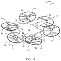
- the example rotorcraft 400 of Fig. 14 is an example of such a rotorcraft 10, and in rotorcraft 400, each circular rotor guard 52 is positioned generally between the two spin volumes of the adjacent rotors of a rotor pair. Such examples further reduce the overall weight of the rotorcraft compared to other configurations of rotor guards.
- each circular rotor guard generally encompasses the spin volumes of both of the adjacent rotors of a rotor pair.
- the circular rotor guards 52 of rotorcraft 500 provide for increased visibility but also result in an increase in overall weight and drag. That said, in some such examples, the circular rotor guard 52 may be configured as a duct to augment lift of the corresponding rotor assembly 14.
- a rotor guard 50 comprises an arced rotor guard 54 that only partially borders the spin volume 24 of a corresponding rotor assembly 14, that is, that does not fully encircle a corresponding rotor assembly 14 as in the example of circular rotor guards 52.
- the arced rotor guard 54 borders at least 50%, at least 40%, at least 30%, at least 20%, at most 75%, at most 65%, at most 55%, and/or at most 45% of a circumferential perimeter of the corresponding spin volume 24.
- a rotor assembly 14 comprises a pair of co-axial rotors 42
- two arced rotor guards 54 partially border the spin volume 24 of the pair of co-axial rotors 42.
- a single arced rotor guard 54 borders each of the pairs of co-axial rotors 42.
- the example rotorcraft 600 of Fig. 16 is an example of such a rotorcraft 10.
- Such examples provide for reduced overall weight of the rotorcraft compared at least to the example rotorcraft 300 and 500 disclosed herein.
- a single arced rotor guard 54 borders the combined spin volume 24 of both of the pair of co-axial rotors 42.
- the example rotorcraft 700 of Fig. 17 is an example of such a rotorcraft 10, and in this illustrated example, each arced rotor guard 54 is positioned generally between the two spin volumes of the adjacent rotors of a rotor pair. Such examples further reduce the overall weight of the rotorcraft 700 compared to rotorcraft 600, for example.
- a rotor guard 50 comprises a combined rotor guard 56 that at least partially borders the spin volume 24 of more than one rotor assembly 14.
- Combined rotor guards 56 provide sufficient visibility of the corresponding spin volumes 24 while reducing overall weight when compared to other configurations of rotor guards.
- the rotorcraft 10 comprises six rotor assemblies 14
- each of two combined rotor guards 56 border the spin volumes 24 of three of the six rotor assemblies 14.
- a combined rotor guard 56 borders at least 50%, at least 40%, at least 30%, at least 20%, at most 75%, at most 65%, at most 55%, and/or at most 45% of a circumferential perimeter of the spin volume 24 of an adjacent corresponding rotor assembly 14. In some examples, a combined rotor guard 56 borders a greater portion of the circumferential perimeter of one or more spin volumes 24 than of the circumferential perimeter of another one of the spin volumes 24. For example, in the schematic representation of Fig. 1 , the two combined rotor guards 56 each border a greater percentage of the circumferential borders of the corresponding spins volumes 24 of the first pair 20 and the second pair 34 of the rotor assemblies 14 than of the third pair 38 of the rotor assemblies.
- the two combined rotor guards 56 each border more than 50% of the spin volumes 24 of the respective rotor assemblies 14 of the first pair 20 and the second pair 34 and less than 50% of the spin volume 24 of the respective rotor assemblies 14 of the third pair 38.
- Other configurations of combined rotor guards 56 are within the scope of the present disclosure and may be incorporated into rotorcraft 10.
- a combined rotor guard 56 comprises at least one segment 58 that is non-parallel to a plane that is perpendicular to a spin axis of an adjacent rotor assembly 14. Such a configuration may be particularly suited for rotorcraft 10 that have canted rotor assemblies 14, as discussed herein.
- Rotorcraft 10 may include more than one configuration of rotor guards 50 and are not required to include only circular rotor guards 52, only arced rotor guards 54, or only combined rotor guards 56, and may include various combinations thereof, as well as other configurations of rotor guards 50.
- rotorcraft 10 further comprise a skid gear 60 that is coupled to the fuselage 12 and that is configured to support the rotorcraft 10 in an upright orientation on a ground surface.
- the skid gear 60 provides a lightweight structure for supporting a rotorcraft 10.
- various forms of ground-contacting structure, or landing gear may be incorporated into a rotorcraft 10, such as (but not limited to) one or more of wheeled structures, passive (e.g., non-motive) structures, motive (e.g., motorized) structures, steerable structures, non-steerable structures, etc.
- rotorcraft 10 illustrative non-exclusive examples of rotorcraft 10 are illustrated.
- the reference numerals from one or more of the schematic illustrations of Figs. 1-4 are used to designate corresponding parts of the rotorcraft of Figs. 5-25 ; however, the examples of Figs. 5-25 are non-exclusive and do not limit rotorcraft 10 to the illustrated embodiments of Figs. 5-25 . That is, rotorcraft 10 may incorporate any number of the various aspects, configurations, characteristics, properties, etc. of rotorcraft 10 that are illustrated in and discussed with reference to the schematic representations of Figs. 1-4 and/or the embodiments of Figs.
- Figs. 5-25 illustrate examples of rotorcraft 10, designated as rotorcraft 300, rotorcraft 400, rotorcraft 500, rotorcraft 600, and rotorcraft 700.
- Each of rotorcraft 300, rotorcraft 400, rotorcraft 500, rotorcraft 600, and rotorcraft 700 comprises an access door 18 on the forward side of the fuselage 12 having an upper section 62 and a lower section 64.
- the spacing 28 between the spin volumes 24 of the first pair 20 of rotor assemblies 14 is greater than 100% of the door-width 22.
- Each of rotorcraft 300, rotorcraft 400, rotorcraft 500, rotorcraft 600, and rotorcraft 700 comprises six rotor assemblies 14, each having a pair of canted co-axial rotors 42.
- Each of rotorcraft 300, rotorcraft 400, rotorcraft 500, rotorcraft 600, and rotorcraft 700 comprises two pairs of curved elongate support arms 32 respectively supporting a first pair 20 and a second pair 34 of rotor assemblies, as well as a pair of aerodynamic structures 40 supporting a third pair 38 of rotor assemblies 14.
- the curved elongate support arms 32 are concave away from the fuselage 12.
- Each of rotorcraft 300, rotorcraft 400, rotorcraft 500, rotorcraft 600, and rotorcraft 700 comprises a non-motive skid gear 60.
- each of rotorcraft 300, rotorcraft 400, rotorcraft 500, rotorcraft 600, and rotorcraft 700 differ in their respective rotor guards 50.
- Rotorcraft 300 ( Figs. 5-13 ) comprises two circular rotor guards 52 for each rotor assembly 14, with a circular rotor guard 52 encircling the spin volume 24 of each rotor of the twelve total rotors.
- rotorcraft 300 is illustrated with its access door 18 in the fully open configuration and with a wheeled cart 70 abutted against the lower section 64 of the access door 18 and with an item of cargo 72 shown in the process of being loaded into or unloaded from the internal compartment 16.
- the lower section 64 of the access door 18 is configured to be aligned with the wheeled cart 70, so that the transfer of the item of cargo 72 to and from the internal compartment 16 is easily accomplished.
- the lower section 64 of the access door 18, when in the fully open configuration has an upper surface that is generally horizontal to the ground surface and parallel to both the floor 66 of the internal compartment 16 and the upper surface of the wheeled cart 70, further facilitating the transfer of the item of cargo 72 to and from the internal compartment 16.
- Rotorcraft 10 and associated cargo loading structures additionally may include material handling structures to further facilitate the transfer of cargo 72, such as (but not limited to) rollers, conveyors, wheels, skates, etc.
- the configuration and use of the access door 18 and associated loading structure illustrated in Fig. 13 in connection with rotorcraft 300 may be utilized with any of the other examples of rotorcraft 10 disclosed herein, including rotorcraft 400, rotorcraft 500, rotorcraft 600, and rotorcraft 700.
- Rotorcraft 400 ( Fig. 14 ) comprises a singular circular rotor guard 52 for each rotor assembly 14, with the single circular rotor guard 52 positioned generally between the two spin volumes of the adjacent rotors.
- the circular rotor guards 52 of rotorcraft 400 are examples of circular rotor guards 52 that intersect or are engaged with other structures of the rotorcraft 400 to fully encircle the respective rotor assemblies 14. More specifically, the forward two circular rotor guards 52 are engaged with the forward two elongate support arms 32, the rear two circular rotor guards 52 are engaged with the rear two elongate support arms 32, and the middle two circular rotor guards 52 are engaged with the aerodynamic structures 40.
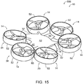
- Rotorcraft 500 ( Fig. 15 ) comprises a singular circular rotor guard 52 for each rotor assembly 14, with the single circular rotor guard 52 generally encompassing the spin volumes of both of the adjacent rotors.
- the circular rotor guards 52 of rotorcraft 500 are examples of circular rotor guards 52 that intersect or are engaged with other structures of the rotorcraft 400 to fully encircle the respective rotor assemblies 14.
- the forward two circular rotor guards 52 are engaged with the forward two elongate support arms 32, the rear two circular rotor guards 52 are engaged with the rear two elongate support arms 32, and the middle two circular rotor guards 52 are engaged with the aerodynamic structures 40.
- Rotorcraft 600 ( Fig. 16 ) comprises a two arced rotor guards 54 for each rotor assembly 14, with an arced rotor guard 54 bordering the spin volume 24 of each rotor of the twelve total rotors.
- Each arced rotor guard 54 of rotorcraft 600 borders about 40% of the circumferential perimeter (i.e., about 145°) of the corresponding spin volume 24.
- Rotorcraft 700 ( Fig. 17 ) comprises a singular arced rotor guard 54 for each rotor assembly 14, with the single arced rotor guard 54 positioned generally between the two spin volumes 24 of the adjacent rotors.
- each arced rotor guards 54 of rotorcraft 700 borders about 40% of the circumferential perimeter (i.e., about 145°) of the corresponding spin volume 24.
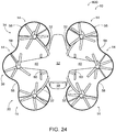
- Rotorcraft 800 ( Figs. 18-25 ) comprises two combined rotor guards 56, one on each side of the rotorcraft 800. Each combined rotor guard 56 borders all three of the rotor assemblies 14 on the respective side of the rotorcraft 800.
- Rotorcraft 800 is an example in which the two combined rotor guards 56 each border more than 50% of the spin volumes 24 of the respective rotor assemblies 14 of the first pair 20 and the second pair 34 of rotor assemblies 14 and less than 50% of the spin volume 24 of the respective rotor assemblies 14 of the third pair 38 of rotor assemblies 14.
- rotorcraft 800 is an example of a rotorcraft 10, in which the combined rotor guards 56 comprise segments 58 that are non-parallel to a plane that is perpendicular to a spin axis of an adjacent rotor assembly 14.
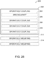
- Fig. 26 schematically provides a flowchart that represents illustrative, non-exclusive examples of methods 200 according to the present disclosure.
- some steps are illustrated in dashed boxes indicating that such steps may be optional or may correspond to an optional version of a method 200 according to the present disclosure. That said, not all methods 200 according to the present disclosure are required to include the steps illustrated in solid boxes.
- the methods 200 and steps illustrated in Fig. 26 are not limiting and other methods and steps are within the scope of the present disclosure, including methods 200 having greater than or fewer than the number of steps illustrated, as understood from the discussions herein.
- methods 200 of assembling a rotorcraft 10 comprise operatively coupling (at 202) at least four rotor assemblies 14 to a fuselage 12.
- the operatively coupling comprises spacing-apart (at 204) spin volumes 24 of a first pair 20 of rotor assemblies 14 to be at least 70%, at least 80%, at least 90%, at least 100%, or at least 110% of a door-width 22 of an access door 18 of the rotorcraft 10.
- the operatively coupling (at 202) comprises operatively coupling (at 206) a first pair 20 of rotor assemblies 14 to a first pair 30 of elongate support arms 32 that extend from opposing lateral sides of the fuselage 12.
- the operatively coupling (at 202) comprises operatively coupling (at 208) a second pair 34 of rotor assemblies 14 to a second pair 36 of elongate support arms 32 that extend from opposing lateral sides of the fuselage 12.
- the operatively coupling comprises operatively coupling (at 210) at least one rotor assembly 14 to each of a pair of aerodynamic structures 40 that extend from opposing lateral sides of the fuselage 12.
- Some methods 200 further comprise operatively mounting (at 212) at least one rotor guard 50 that borders the spin volume 24 of at least one rotor assembly 14 of the rotorcraft 10. When so mounted, the rotor guard 50 provides a visual indication of the spin volume 24 of the associated rotor assembly 14.
- Some methods further comprise operatively mounting (at 214) a skid gear 60 or other ground-contacting structure to the fuselage 12.
- the terms “adapted” and “configured” mean that the element, component, or other subject matter is designed and/or intended to perform a given function. Thus, the use of the terms “adapted” and “configured” should not be construed to mean that a given element, component, or other subject matter is simply “capable of” performing a given function but that the element, component, and/or other subject matter is specifically selected, created, implemented, utilized, programmed, and/or designed for the purpose of performing the function. It is also within the scope of the present disclosure that elements, components, and/or other recited subject matter that is recited as being adapted to perform a particular function may additionally or alternatively be described as being configured to perform that function, and vice versa. Similarly, subject matter that is recited as being configured to perform a particular function may additionally or alternatively be described as being operative to perform that function.
- the term "and/or" placed between a first entity and a second entity means one of (1) the first entity, (2) the second entity, and (3) the first entity and the second entity.
- Multiple entries listed with “and/or” should be construed in the same manner, i.e., "one or more" of the entities so conjoined.
- Other entities optionally may be present other than the entities specifically identified by the "and/or” clause, whether related or unrelated to those entities specifically identified.
- a reference to "A and/or B,” when used in conjunction with open-ended language such as “comprising,” may refer, in one example, to A only (optionally including entities other than B); in another example, to B only (optionally including entities other than A); in yet another example, to both A and B (optionally including other entities).
- These entities may refer to elements, actions, structures, steps, operations, values, and the like.
Landscapes
- Engineering & Computer Science (AREA)
- Aviation & Aerospace Engineering (AREA)
- Mechanical Engineering (AREA)
- Remote Sensing (AREA)
- Chemical & Material Sciences (AREA)
- Combustion & Propulsion (AREA)
- Laminated Bodies (AREA)
- Tires In General (AREA)
- Aiming, Guidance, Guns With A Light Source, Armor, Camouflage, And Targets (AREA)
Abstract
Description
- The present disclosure relates to multi-rotor rotorcraft.
- Multi-rotor rotorcraft, including autonomous rotorcraft, are increasingly being developed for transporting cargo and human passengers. Such rotorcraft have different design considerations than traditional helicopters and recreational autonomous rotorcraft, including weight considerations, safety considerations, considerations associated with loading and unloading cargo and/or human passengers to and from a rotorcraft, and other considerations.
- Multi-rotor rotorcraft and methods of assembling a multi-rotor rotorcraft are disclosed herein. Multi-rotor rotorcraft comprise a fuselage and at least four rotor assemblies that are operatively supported by and spaced-around the fuselage. Each of the at least four rotor assemblies defines a spin volume and a spin diameter. Some multi-rotor rotorcraft further comprise at least one rotor guard that is fixed relative to the fuselage, that borders the spin volume of at least one of the at least four rotor assemblies, and that is configured to provide a visual indication of and safety barrier to the spin volume of the at least one of the at least four rotor assemblies. Various configurations of rotor guards are disclosed.
-
-
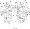
Fig. 1 is a schematic plan view diagram representing example multi-rotor rotorcraft according to the present disclosure. -
Fig. 2 is a schematic end view diagram representing example multi-rotor rotorcraft according to the present disclosure with a two-part access door shown closed in a closed configuration. -
Fig. 3 is another schematic end view diagram representing example multi-rotor rotorcraft according to the present disclosure with a two-part access door shown in a fully open configuration. -
Fig. 4 is a schematic side view diagram representing example multi-rotor rotorcraft according to the present disclosure. -
Fig. 5 is a perspective view of an example multi-rotor rotorcraft according to the present disclosure. -
Fig. 6 is another perspective view of the multi-rotor rotorcraft ofFig. 5 . -
Fig. 7 is a front view of the multi-rotor rotorcraft ofFig. 5 . -
Fig. 8 is a rear view of the multi-rotor rotorcraft ofFig. 5 . -
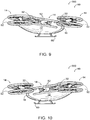
Fig. 9 is a right side view of the multi-rotor rotorcraft ofFig. 5 . -
Fig. 10 is a left side view of the multi-rotor rotorcraft ofFig. 5 . -
Fig. 11 is a top view of the multi-rotor rotorcraft ofFig. 5 . -
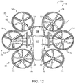
Fig. 12 is a bottom view of the multi-rotor rotorcraft ofFig. 5 . -
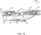
Fig. 13 is a left side view of the multi-rotor rotorcraft ofFig. 5 , with its access door in a fully open configuration and shown receiving or dispensing cargo from or to a wheeled cart. -
Fig. 14 is a perspective view of another example multi-rotor rotorcraft according to the present disclosure. -
Fig. 15 is a perspective view of another example multi-rotor rotorcraft according to the present disclosure. -
Fig. 16 is a perspective view of another example multi-rotor rotorcraft according to the present disclosure. -
Fig. 17 is a perspective view of another example multi-rotor rotorcraft according to the present disclosure. -
Fig. 18 is a perspective view of another example multi-rotor rotorcraft according to the present disclosure. -
Fig. 19 is another perspective view of the multi-rotor rotorcraft ofFig. 18 . -
Fig. 20 is a front view of the multi-rotor rotorcraft ofFig. 18 . -
Fig. 21 is a rear view of the multi-rotor rotorcraft ofFig. 18 . -
Fig. 22 is a right side view of the multi-rotor rotorcraft ofFig. 18 . -
Fig. 23 is a left side view of the multi-rotor rotorcraft ofFig. 18 . -
Fig. 24 is a top view of the multi-rotor rotorcraft ofFig. 18 . -
Fig. 25 is a bottom view of the multi-rotor rotorcraft ofFig. 18 . -
Fig. 26 is a schematic diagram representing example methods according to the present disclosure. - Multi-rotor rotorcraft are disclosed herein. Generally, in
Fig. 1 , elements that are likely to be included in a given example are illustrated in solid lines, while elements that are optional to a given example are illustrated in broken lines. However, elements that are illustrated in solid lines are not essential to all examples of the present disclosure, and an element shown in solid lines may be omitted from a particular example without departing from the scope of the present disclosure. Moreover, elements that are illustrated in broken lines may be important to some examples of the present disclosure. - With reference to
Fig. 1 ,multi-rotor rotorcraft 10, which may be referred to herein simply asrotorcraft 10 or as amulti-rotor vehicle 10, comprise afuselage 12 and at least fourrotor assemblies 14 that are operatively supported by and spaced-around thefuselage 12. Each of the at least fourrotor assemblies 14 defines aspin volume 24 and aspin diameter 26. As used herein, a "spin volume" is an imaginary cylindrical volume defined by the outer most extent of a rotor assembly's rotors when spinning. As used herein, a "spin diameter" is the diameter of a corresponding spin volume. - Some
rotorcraft 10 may be unmanned and/or autonomous and therefore may be described as autonomous rotorcraft. Additionally or alternatively, somerotorcraft 10 may be pilot operated or at least configured to be pilot operated. In some such examples, the pilot may be onboard therotorcraft 10, and thus the rotorcraft may be described as a manned rotorcraft. In some examples, rotorcraft 10 may be configured to be piloted remotely and therefore may be described as a remote-controlled rotorcraft. Rotorcraft 10 may be used to transport a payload, such as cargo or human passengers. - In some examples of
rotorcraft 10, thefuselage 12 comprises aninternal compartment 16 and anaccess door 18 that has a door-width 22. Theaccess door 18 provides selective access to theinternal compartment 16. Some examples ofrotorcraft 10 include more than oneaccess door 18 as optionally and schematically illustrated inFig. 1 . Various configurations ofaccess doors 18 may be incorporated into arotorcraft 10, including access doors that are hinged or otherwise pivot between a closed configuration and a fully open configuration. With reference toFigs. 2 and 3 , in some examples ofrotorcraft 10, theaccess door 18 has more than one section, such as anupper section 62 and alower section 64 that are configured to collectively provide selective access to theinternal compartment 16. In some such examples, when theaccess door 18 is in the fully open configuration, thelower section 64 is at or below the level of afloor 66 if theinternal compartment 16, when therotorcraft 10 is operatively positioned on a horizontal ground surface. Accordingly, a payload may be easily loaded into and unloaded from theinternal compartment 16 when theaccess door 18 is in the fully open configuration, for example from an adjacent loading structure, such as a wheeled cart. In some such examples, thelower section 64 may serve as a ramp from the ground surface or other loading structure to thefloor 66 of theinternal compartment 16. In other examples ofrotorcraft 10, theaccess door 18 may only include a single section that translates and/or pivots upward to provide selective access to theinternal compartment 16. In yet other examples ofrotorcraft 10, theaccess door 18 may only include a single section that translates and/or pivots downward to provide selective access to theinternal compartment 16. In some examples ofrotorcraft 10, theinternal compartment 16 has a volume of at least 0.5 cubic meters (m3), of at least 1 m3, of at least 1.5 m3, of at least 2 m3, of between 0.5 m3 and 3 m3, and/or at most 3 m3. - Referring back to
Fig. 1 , in some such examples ofrotorcraft 10 that include anaccess door 18, the at least fourrotor assemblies 14 comprise afirst pair 20 ofrotor assemblies 14 positioned on opposing sides of theaccess door 18, and aspacing 28 between thespin volumes 24 of thefirst pair 20 ofrotor assemblies 14 is at least 70%, at least 80%, at least 90%, at least 100%, at least 110%, or at least 120% of the door-width 22. In some applications, having thespacing 28 at least 100% of the door-width is important. Accordingly, a rectangular prismatic volume of space extending from theaccess door 18 away from the fuselage may be substantially void or completely void of structure of therotorcraft 10, including therotor assemblies 14 and related hardware, such as optional rotor guards 50 discussed herein. As a result, the loading and unloading of payload to and from theinternal compartment 16 may be safely accomplished. - In some such examples of
rotorcraft 10, theinternal compartment 16 is sized to selectively receive cargo, and theaccess door 18 is sized to permit loading and unloading of cargo into and from theinternal compartment 16.Such rotorcraft 10 may be described as cargo aircraft. - Additionally or alternatively, in some examples of
rotorcraft 10, theinternal compartment 16 is configured for transportation of at least one human passenger, and theaccess door 18 is sized for entry and exit of the at least one human passenger to and from theinternal compartment 16.Such rotorcraft 10 may be described as passenger aircraft. - With continued reference to
Fig. 1 , in some examples ofrotorcraft 10, the at least fourrotor assemblies 14 comprise afirst pair 20 of rotor assemblies positioned on opposing lateral sides of thefuselage 12, and therotorcraft 10 further comprises afirst pair 30 ofelongate support arms 32.Elongate support arms 32 additionally or alternatively may be described as support beams or booms. Eachelongate support arm 32 interconnects a respective one of thefirst pair 20 ofrotor assemblies 14 to thefuselage 12. The lengths of theelongate support arms 32, and thus the location of therespective rotor assemblies 14 relative to thefuselage 12, may be optimized for maneuverability and stability of therotorcraft 10, as well as for thespacing 28 discussed above. - As schematically illustrated in
Fig. 1 , in some examples, eachelongate support arm 32 of thefirst pair 30 ofelongate support arms 32 extends along a respective curved path between thefuselage 12 and the respective one of thefirst pair 20 ofrotor assemblies 14. In some such examples, when viewed from above, each respective curved path is concave away from thefuselage 12. However, also within the scope of the present disclosure areelongate support arms 32 whose respective curved paths are convex away from thefuselage 12, as well aselongate support arms 32 that are straight or generally straight. Curved support arms may provide for reduced weight compared to similarly configured rotorcraft with straight or substantially straight booms that support respective rotor assemblies. Additionally or alternatively, curved support arms may result in reduced acoustic interference noise compared to similarly configured rotorcraft with straight or substantially straight booms that support respective rotor assemblies. - In some examples of
rotorcraft 10, the at least fourrotor assemblies 14 further comprise asecond pair 34 ofrotor assemblies 14 that also are positioned on the opposing lateral sides of thefuselage 12, and therotorcraft 10 further comprises asecond pair 36 ofelongate support arms 32. Eachelongate support arm 32 of thesecond pair 36 interconnects a respective one of thesecond pair 34 ofrotor assemblies 14 to thefuselage 12. In some such examples, eachelongate support arm 32 of thesecond pair 36 ofelongate support arms 32 extends along a respective curved path between thefuselage 12 and the respective one of thesecond pair 34 ofrotor assemblies 14. In some such examples, when viewed from above (e.g., when therotorcraft 10 is positioned on a flat ground surface), each respective curved path is concave away from thefuselage 12. - With continued reference to
Fig. 1 , some examples ofrotorcraft 10 further comprise a pair ofaerodynamic structures 40 that extend from opposing lateral sides of thefuselage 12. In some examples, theaerodynamic structures 40 are wings that provide aerodynamic lift for therotorcraft 10. In some examples, at least onerotor assembly 14 is supported by each one of the pair ofaerodynamic structures 40 and thus may be described as aerodynamic lift support structures. In some such examples, the at least fourrotor assemblies 14 comprise (i) afirst pair 20 ofrotor assemblies 14 positioned on opposing lateral sides of thefuselage 12 at a forward region of therotorcraft 10, (ii) asecond pair 34 ofrotor assemblies 14 positioned on the opposing lateral sides of thefuselage 12 at a rearward region of therotorcraft 10, and (iii) athird pair 38 ofrotor assemblies 14 positioned on the opposing lateral sides of thefuselage 12 at a middle region of the rotorcraft, with each of thethird pair 38 ofrotor assemblies 14 being supported by one of the pair ofaerodynamic structures 40. That is, in some such examples, theaerodynamic structures 40 extend generally from opposing lateral sides of a middle region of therotorcraft 10, which may facilitate flight stability of therotorcraft 10. - With continued reference to
Fig. 1 , in some examples ofrotorcraft 10, eachrotor assembly 14 of the at least fourrotor assemblies 14 comprises a pair ofco-axial rotors 42. In some such examples, the pair ofco-axial rotors 42 of a first set ofrotor assemblies 14 are configured to counter-rotate, and the pair ofco-axial rotors 42 of a second set ofrotor assemblies 14 are configured to co-rotate. In the schematic example ofFig. 1 , therotor assemblies 14 of thefirst pair 20 and thesecond pair 34 are co-rotating rotor assemblies, and the rotor assemblies of thethird pair 38 are counter-rotating rotor assemblies; however, other configurations are within the scope of the present disclosure. Also, as schematically represented inFig. 4 , some examples ofrotorcraft 10 compriserotor assemblies 14 that are canted with respect to one or more of a yaw axis, a pitch axis, and/or a roll axis of therotorcraft 10. Examples of canted counter-rotating and co-rotating rotor assemblies incorporated into a rotorcraft, and which may be incorporated into arotorcraft 10 according to the present disclosure, are disclosed inU.S. Patent Application No. 16/035,245 . - In the illustrated examples, each
rotor 42 has three blades; however,rotorcraft 10 are not limited to having three-bladed rotors, and any suitable number of blades may be utilized, including two-bladed rotors, three-bladed rotors, four-bladed rotors, or rotors having more than four blades. - Referring back to
Fig. 1 , somerotorcraft 10 further comprise at least onerotor guard 50 that is fixed relative to thefuselage 12, that borders thespin volume 24 of at least onerotor assembly 14, and that is configured to provide a visual indication of thespin volume 24 of the associatedrotor assembly 14. Accordingly, when the rotors of the associatedrotor assembly 14 are spinning and may be difficult, impossible, or near impossible for a human to see, the associatedrotor guard 50 provides a visual indication of where thespin volume 24 is located. In some examples, rotor guards 50 additionally or alternatively may be described as providing a safety barrier. In some examples, at least onerotor guard 50 borders each of therotor assemblies 14 of arotorcraft 10. In some examples, therotor guard 50 borders thespin volume 24 of arotor assembly 14 within a threshold distance. In some examples, the threshold distance is less than 10 cm, less than 5 cm, less than 3 cm, less than 2 cm, or less than 1 cm. In some examples, the threshold distance is at most 30% of thecorresponding spin diameter 26, at most 20% of thecorresponding spin diameter 26, at most 10% of thecorresponding spin diameter 26, or at most 5% of thecorresponding spin diameter 26. Accordingly, rotor guards 50 may be provided in close proximity to the corresponding rotor assembly orrotor assemblies 14 without significant overall increase in the size or volume of arotorcraft 10. Rotor guards 50 may be fixed relative to the fuselage in any suitable manner. For example, as schematically represented inFig. 1 , rotor guards 50 may be supported by one ormore support arms 51 that interconnect the rotor guards 50 to the associatedrotor assemblies 14; however, other configurations also are within the scope of the present disclosure, including support arms or other structures that interconnect rotor guards directly to thefuselage 12, to anelongate support arm 32, or to anaerodynamic structure 40. - In some examples, a
rotor guard 50 additionally may function as a duct to augment lift of thecorresponding rotor assembly 14. Typically, in such examples, the threshold distance between thespin volume 24 and therotor guard 50 is less than 1 cm. - In some examples, a
rotor guard 50 is substantially parallel to a plane that is perpendicular to a spin axis of the correspondingadjacent rotor assembly 14 that it borders. In other words, in some examples, a rotor guard is substantially parallel to thespin diameter 26 of acorresponding rotor assembly 14. As a result, therotor guard 50 provides a visual indication of the location of, and in some examples the extent of, thespin volume 24. - In some examples of
rotorcraft 10, arotor guard 50 comprises acircular rotor guard 52 that substantially encircles thespin volume 24 of acorresponding rotor assembly 14. By substantially encircle, it is meant that acircular rotor guard 52 does not necessarily fully encircle 360° of thespin volume 24 of thecorresponding rotor assembly 14, but rather at least 75% of thespin volume 24. In some examples, acircular rotor guard 52 intersects or is engaged with another structure of therotorcraft 10, such as (but not limited to) anelongate support arm 32 or anaerodynamic structure 40, such that thecircular rotor guard 52 and the other structure collectively fully encircle thespin volume 24 of thecorresponding rotor assembly 14. - In some such examples in which a
rotor assembly 14 comprises a pair ofco-axial rotors 42, twocircular rotor guards 52 substantially encircle thespin volume 24 of the pair ofco-axial rotors 42. In other words, in such examples, a singlecircular rotor guard 52 borders each of the pair ofco-axial rotors 42. Theexample rotorcraft 300 ofFigs. 5-13 is an example of such arotorcraft 10. Such examples may provide for maximum visibility of therotor assemblies 14 while reducing overall weight of the rotorcraft compared to other configurations of rotor guards. In other such examples in which arotor assembly 14 comprises a pair ofco-axial rotors 42, a singlecircular rotor guard 52 substantially encircles the combinedspin volume 24 of both of the pair ofco-axial rotors 42. Theexample rotorcraft 400 ofFig. 14 is an example of such arotorcraft 10, and inrotorcraft 400, eachcircular rotor guard 52 is positioned generally between the two spin volumes of the adjacent rotors of a rotor pair. Such examples further reduce the overall weight of the rotorcraft compared to other configurations of rotor guards. Theexample rotorcraft 500 ofFig. 15 is another example of such arotorcraft 10, but inrotorcraft 500, each circular rotor guard generally encompasses the spin volumes of both of the adjacent rotors of a rotor pair. When compared torotorcraft 400, thecircular rotor guards 52 ofrotorcraft 500 provide for increased visibility but also result in an increase in overall weight and drag. That said, in some such examples, thecircular rotor guard 52 may be configured as a duct to augment lift of thecorresponding rotor assembly 14. - Referring back to
Fig. 1 , in some examples ofrotorcraft 10, arotor guard 50 comprises an arcedrotor guard 54 that only partially borders thespin volume 24 of acorresponding rotor assembly 14, that is, that does not fully encircle acorresponding rotor assembly 14 as in the example of circular rotor guards 52. In some such examples, the arcedrotor guard 54 borders at least 50%, at least 40%, at least 30%, at least 20%, at most 75%, at most 65%, at most 55%, and/or at most 45% of a circumferential perimeter of thecorresponding spin volume 24. In some such examples, in which arotor assembly 14 comprises a pair ofco-axial rotors 42, two arcedrotor guards 54 partially border thespin volume 24 of the pair ofco-axial rotors 42. In other words, in such examples, a single arcedrotor guard 54 borders each of the pairs ofco-axial rotors 42. Theexample rotorcraft 600 ofFig. 16 is an example of such arotorcraft 10. Such examples provide for reduced overall weight of the rotorcraft compared at least to theexample rotorcraft rotor assembly 14 comprises a pair of co-axial rotors, a single arcedrotor guard 54 borders the combinedspin volume 24 of both of the pair ofco-axial rotors 42. Theexample rotorcraft 700 ofFig. 17 is an example of such arotorcraft 10, and in this illustrated example, each arcedrotor guard 54 is positioned generally between the two spin volumes of the adjacent rotors of a rotor pair. Such examples further reduce the overall weight of therotorcraft 700 compared torotorcraft 600, for example. - Referring back to
Figs. 1 and4 , in some examples ofrotorcraft 10, arotor guard 50 comprises a combinedrotor guard 56 that at least partially borders thespin volume 24 of more than onerotor assembly 14.Combined rotor guards 56 provide sufficient visibility of thecorresponding spin volumes 24 while reducing overall weight when compared to other configurations of rotor guards. In the schematic representation ofFigs. 1 and4 , as well as theexample rotorcraft 800 ofFigs. 18-25 , in which therotorcraft 10 comprises sixrotor assemblies 14, each of two combinedrotor guards 56 border thespin volumes 24 of three of the sixrotor assemblies 14. Other configurations of combinedrotor guards 56 are within the scope of the present disclosure and may be incorporated into arotorcraft 10, such as depending on the total number ofrotor assemblies 14, the relative spacing and positioning of therotor assemblies 14, the canting (if any) of therotor assemblies 14 orrotors 42 thereof, etc. - In some examples, a combined
rotor guard 56 borders at least 50%, at least 40%, at least 30%, at least 20%, at most 75%, at most 65%, at most 55%, and/or at most 45% of a circumferential perimeter of thespin volume 24 of an adjacentcorresponding rotor assembly 14. In some examples, a combinedrotor guard 56 borders a greater portion of the circumferential perimeter of one ormore spin volumes 24 than of the circumferential perimeter of another one of thespin volumes 24. For example, in the schematic representation ofFig. 1 , the two combinedrotor guards 56 each border a greater percentage of the circumferential borders of the correspondingspins volumes 24 of thefirst pair 20 and thesecond pair 34 of therotor assemblies 14 than of thethird pair 38 of the rotor assemblies. For example, as schematically represented, the two combinedrotor guards 56 each border more than 50% of thespin volumes 24 of therespective rotor assemblies 14 of thefirst pair 20 and thesecond pair 34 and less than 50% of thespin volume 24 of therespective rotor assemblies 14 of thethird pair 38. Other configurations of combinedrotor guards 56 are within the scope of the present disclosure and may be incorporated intorotorcraft 10. - With reference to
Fig. 4 , in some examples, a combinedrotor guard 56 comprises at least onesegment 58 that is non-parallel to a plane that is perpendicular to a spin axis of anadjacent rotor assembly 14. Such a configuration may be particularly suited forrotorcraft 10 that have cantedrotor assemblies 14, as discussed herein. -
Rotorcraft 10 may include more than one configuration ofrotor guards 50 and are not required to include onlycircular rotor guards 52, only arcedrotor guards 54, or only combinedrotor guards 56, and may include various combinations thereof, as well as other configurations of rotor guards 50. In some applications, for example, it may be desirable to utilizecircular rotor guards 52 in positons on arotorcraft 10 that are adjacent to areas where personnel or autonomous loading structures are routinely operating, such as in connection with the loading and/or unloading of cargo or human passengers, while other configurations ofrotor guards 50 may be utilized elsewhere on such arotorcraft 10. - With reference back to
Fig. 1 , some examples ofrotorcraft 10 further comprise askid gear 60 that is coupled to thefuselage 12 and that is configured to support therotorcraft 10 in an upright orientation on a ground surface. When provided, theskid gear 60 provides a lightweight structure for supporting arotorcraft 10. However, various forms of ground-contacting structure, or landing gear, may be incorporated into arotorcraft 10, such as (but not limited to) one or more of wheeled structures, passive (e.g., non-motive) structures, motive (e.g., motorized) structures, steerable structures, non-steerable structures, etc. - Turning now to
Figs. 5-25 , illustrative non-exclusive examples ofrotorcraft 10 are illustrated. Where appropriate, the reference numerals from one or more of the schematic illustrations ofFigs. 1-4 are used to designate corresponding parts of the rotorcraft ofFigs. 5-25 ; however, the examples ofFigs. 5-25 are non-exclusive and do not limitrotorcraft 10 to the illustrated embodiments ofFigs. 5-25 . That is,rotorcraft 10 may incorporate any number of the various aspects, configurations, characteristics, properties, etc. ofrotorcraft 10 that are illustrated in and discussed with reference to the schematic representations ofFigs. 1-4 and/or the embodiments ofFigs. 5-25 , as well as variations thereof, without requiring the inclusion of all such aspects, configurations, characteristics, properties, etc. For the purpose of brevity, each previously discussed component, part, portion, aspect, region, etc. or variants thereof may not be discussed, illustrated, and/or labeled again with respect to the embodiments ofFigs. 5-25 ; however, it is within the scope of the present disclosure that the previously discussed features, variants, etc. may be utilized with the embodiments ofFigs. 5-25 . -
Figs. 5-25 illustrate examples ofrotorcraft 10, designated asrotorcraft 300,rotorcraft 400,rotorcraft 500,rotorcraft 600, androtorcraft 700. Each ofrotorcraft 300,rotorcraft 400,rotorcraft 500,rotorcraft 600, androtorcraft 700 comprises anaccess door 18 on the forward side of thefuselage 12 having anupper section 62 and alower section 64. The spacing 28 between thespin volumes 24 of thefirst pair 20 ofrotor assemblies 14 is greater than 100% of the door-width 22. Each ofrotorcraft 300,rotorcraft 400,rotorcraft 500,rotorcraft 600, androtorcraft 700 comprises sixrotor assemblies 14, each having a pair of cantedco-axial rotors 42. Each ofrotorcraft 300,rotorcraft 400,rotorcraft 500,rotorcraft 600, androtorcraft 700 comprises two pairs of curvedelongate support arms 32 respectively supporting afirst pair 20 and asecond pair 34 of rotor assemblies, as well as a pair ofaerodynamic structures 40 supporting athird pair 38 ofrotor assemblies 14. Moreover, the curvedelongate support arms 32 are concave away from thefuselage 12. Each ofrotorcraft 300,rotorcraft 400,rotorcraft 500,rotorcraft 600, androtorcraft 700 comprises anon-motive skid gear 60. However, each ofrotorcraft 300,rotorcraft 400,rotorcraft 500,rotorcraft 600, androtorcraft 700 differ in their respective rotor guards 50. - Rotorcraft 300 (
Figs. 5-13 ) comprises twocircular rotor guards 52 for eachrotor assembly 14, with acircular rotor guard 52 encircling thespin volume 24 of each rotor of the twelve total rotors. InFig. 13 ,rotorcraft 300 is illustrated with itsaccess door 18 in the fully open configuration and with awheeled cart 70 abutted against thelower section 64 of theaccess door 18 and with an item ofcargo 72 shown in the process of being loaded into or unloaded from theinternal compartment 16. In the illustrated example, thelower section 64 of theaccess door 18 is configured to be aligned with thewheeled cart 70, so that the transfer of the item ofcargo 72 to and from theinternal compartment 16 is easily accomplished. Moreover, in the illustrated example, thelower section 64 of theaccess door 18, when in the fully open configuration has an upper surface that is generally horizontal to the ground surface and parallel to both thefloor 66 of theinternal compartment 16 and the upper surface of thewheeled cart 70, further facilitating the transfer of the item ofcargo 72 to and from theinternal compartment 16.Rotorcraft 10 and associated cargo loading structures additionally may include material handling structures to further facilitate the transfer ofcargo 72, such as (but not limited to) rollers, conveyors, wheels, skates, etc. The configuration and use of theaccess door 18 and associated loading structure illustrated inFig. 13 in connection withrotorcraft 300 may be utilized with any of the other examples ofrotorcraft 10 disclosed herein, includingrotorcraft 400,rotorcraft 500,rotorcraft 600, androtorcraft 700. - Rotorcraft 400 (
Fig. 14 ) comprises a singularcircular rotor guard 52 for eachrotor assembly 14, with the singlecircular rotor guard 52 positioned generally between the two spin volumes of the adjacent rotors. Moreover, thecircular rotor guards 52 ofrotorcraft 400 are examples ofcircular rotor guards 52 that intersect or are engaged with other structures of therotorcraft 400 to fully encircle therespective rotor assemblies 14. More specifically, the forward twocircular rotor guards 52 are engaged with the forward twoelongate support arms 32, the rear twocircular rotor guards 52 are engaged with the rear twoelongate support arms 32, and the middle twocircular rotor guards 52 are engaged with theaerodynamic structures 40. - Rotorcraft 500 (
Fig. 15 ) comprises a singularcircular rotor guard 52 for eachrotor assembly 14, with the singlecircular rotor guard 52 generally encompassing the spin volumes of both of the adjacent rotors. Moreover, as withrotorcraft 400, thecircular rotor guards 52 ofrotorcraft 500 are examples ofcircular rotor guards 52 that intersect or are engaged with other structures of therotorcraft 400 to fully encircle therespective rotor assemblies 14. More specifically, similar torotorcraft 400, the forward twocircular rotor guards 52 are engaged with the forward twoelongate support arms 32, the rear twocircular rotor guards 52 are engaged with the rear twoelongate support arms 32, and the middle twocircular rotor guards 52 are engaged with theaerodynamic structures 40. - Rotorcraft 600 (
Fig. 16 ) comprises a two arcedrotor guards 54 for eachrotor assembly 14, with an arcedrotor guard 54 bordering thespin volume 24 of each rotor of the twelve total rotors. Each arcedrotor guard 54 ofrotorcraft 600 borders about 40% of the circumferential perimeter (i.e., about 145°) of thecorresponding spin volume 24. - Rotorcraft 700 (
Fig. 17 ) comprises a singular arcedrotor guard 54 for eachrotor assembly 14, with the single arcedrotor guard 54 positioned generally between the twospin volumes 24 of the adjacent rotors. Similarly to rotorcraft 600 ofFig. 16 , each arcedrotor guards 54 ofrotorcraft 700 borders about 40% of the circumferential perimeter (i.e., about 145°) of thecorresponding spin volume 24. - Rotorcraft 800 (
Figs. 18-25 ) comprises two combinedrotor guards 56, one on each side of therotorcraft 800. Each combinedrotor guard 56 borders all three of therotor assemblies 14 on the respective side of therotorcraft 800.Rotorcraft 800 is an example in which the two combinedrotor guards 56 each border more than 50% of thespin volumes 24 of therespective rotor assemblies 14 of thefirst pair 20 and thesecond pair 34 ofrotor assemblies 14 and less than 50% of thespin volume 24 of therespective rotor assemblies 14 of thethird pair 38 ofrotor assemblies 14. Moreover,rotorcraft 800 is an example of arotorcraft 10, in which the combinedrotor guards 56 comprisesegments 58 that are non-parallel to a plane that is perpendicular to a spin axis of anadjacent rotor assembly 14. -
Fig. 26 schematically provides a flowchart that represents illustrative, non-exclusive examples ofmethods 200 according to the present disclosure. InFig. 26 , some steps are illustrated in dashed boxes indicating that such steps may be optional or may correspond to an optional version of amethod 200 according to the present disclosure. That said, not allmethods 200 according to the present disclosure are required to include the steps illustrated in solid boxes. Themethods 200 and steps illustrated inFig. 26 are not limiting and other methods and steps are within the scope of the present disclosure, includingmethods 200 having greater than or fewer than the number of steps illustrated, as understood from the discussions herein. - As schematically represented in
Fig. 26 ,methods 200 of assembling arotorcraft 10 comprise operatively coupling (at 202) at least fourrotor assemblies 14 to afuselage 12. - In some
methods 200, the operatively coupling (at 202) comprises spacing-apart (at 204)spin volumes 24 of afirst pair 20 ofrotor assemblies 14 to be at least 70%, at least 80%, at least 90%, at least 100%, or at least 110% of a door-width 22 of anaccess door 18 of therotorcraft 10. - In some
methods 200, the operatively coupling (at 202) comprises operatively coupling (at 206) afirst pair 20 ofrotor assemblies 14 to afirst pair 30 ofelongate support arms 32 that extend from opposing lateral sides of thefuselage 12. In somesuch methods 200, the operatively coupling (at 202) comprises operatively coupling (at 208) asecond pair 34 ofrotor assemblies 14 to asecond pair 36 ofelongate support arms 32 that extend from opposing lateral sides of thefuselage 12. - In some
methods 200, the operatively coupling (at 202) comprises operatively coupling (at 210) at least onerotor assembly 14 to each of a pair ofaerodynamic structures 40 that extend from opposing lateral sides of thefuselage 12. - Some
methods 200 further comprise operatively mounting (at 212) at least onerotor guard 50 that borders thespin volume 24 of at least onerotor assembly 14 of therotorcraft 10. When so mounted, therotor guard 50 provides a visual indication of thespin volume 24 of the associatedrotor assembly 14. - Some methods further comprise operatively mounting (at 214) a
skid gear 60 or other ground-contacting structure to thefuselage 12. - Illustrative, non-exclusive examples of inventive subject matter according to the present disclosure are described in the following enumerated paragraphs:
- A. A multi-rotor rotorcraft, comprising:
- a fuselage; and
- at least four rotor assemblies operatively supported by and spaced-around the fuselage, wherein each of the at least four rotor assemblies defines a spin volume and a spin diameter.
- A1. The multi-rotor rotorcraft of paragraph A,
wherein the fuselage comprises an internal compartment and an access door having a door-width that provides selective access to the internal compartment;
wherein the at least four rotor assemblies comprise a first pair of rotor assemblies positioned on opposing sides of the access door; and
wherein a spacing between the spin volumes of the first pair of rotor assemblies is at least 70%, at least 80%, at least 90%, at least 100%, at least 110%, or at least 120% of the door-width.- A1.1. The multi-rotor rotorcraft of paragraph A1, wherein the internal compartment is sized to selectively receive cargo, and wherein the access door is sized to permit loading and unloading of cargo into and from the internal compartment.
- A1.2. The multi-rotor rotorcraft of paragraph A1, wherein the internal compartment is configured for transportation of at least one human passenger, and wherein the access door is sized for entry and exit of the at least one human passenger to and from the internal compartment.
- A1.3. The multi-rotor rotorcraft of any of paragraphs A1-A1.2, wherein the internal compartment has a volume of at least 0.5 cubic meters (m3), of at least 1 m3, of at least 1.5 m3, of at least 2 m3, of between 0.5 m3 and 3 m3, and/or at most 3 m3, optionally for transporting cargo.
- A2. The multi-rotor rotorcraft of any of paragraphs A-A1.3,
wherein the at least four rotor assemblies comprise a/the first pair of rotor assemblies positioned on opposing lateral sides of the fuselage; and
wherein the multi-rotor rotorcraft further comprises a first pair of elongate support arms, each interconnecting a respective one of the first pair of rotor assemblies to the fuselage.- A2.1. The multi-rotor rotorcraft of paragraph A2, wherein each elongate support arm of the first pair of elongate support arms extends along a respective curved path between the fuselage and the respective one of the first pair of rotor assemblies.
A2.1.1. The multi-rotor rotorcraft of paragraph A2.1, wherein, when viewed from above, each respective curved path is concave away from the fuselage. - A2.2. The multi-rotor rotorcraft of any of paragraphs A2-A2.1.1,
wherein the at least four rotor assemblies further comprise a second pair of rotor assemblies positioned on the opposing lateral sides of the fuselage; and
wherein the multi-rotor rotorcraft further comprises a second pair of elongate support arms, each interconnecting a respective one of the second pair of rotor assemblies to the fuselage.
A2.2.1. The multi-rotor rotorcraft of paragraph A2.2, wherein each elongate support arm of the second pair of elongate support arms extends along a respective curved path between the fuselage and the respective one of the second pair of rotor assemblies.
A2.2.1.1. The multi-rotor rotorcraft of paragraph A2.2.1, wherein, when viewed from above, each respective curved path is concave away from the fuselage.
- A2.1. The multi-rotor rotorcraft of paragraph A2, wherein each elongate support arm of the first pair of elongate support arms extends along a respective curved path between the fuselage and the respective one of the first pair of rotor assemblies.
- A3. The multi-rotor rotorcraft of any of paragraphs A-A2.2.1.1, further comprising a pair of aerodynamic structures extending from opposing lateral sides of the fuselage, wherein at least one rotor assembly of the at least four rotor assemblies is supported by each of the pair of aerodynamic structures.
- A3.1. The multi-rotor rotorcraft of paragraph A3,
wherein the at least four rotor assemblies comprise:- a/the first pair of rotor assemblies positioned on opposing lateral sides of the fuselage;
- a/the second pair of rotor assemblies positioned on the opposing lateral sides of the fuselage; and
- a third pair of rotor assemblies positioned on the opposing lateral sides of the fuselage; and
A3.1.1. The multi-rotor rotorcraft of paragraph A3.1, wherein the third pair of rotor assemblies is positioned between the first pair of rotor assemblies and the second pair of rotor assemblies. - A3.2. The multi-rotor rotorcraft of any of paragraphs A3-A3.1.1, wherein the pair of aerodynamic structures is a pair of wings.
- A3.1. The multi-rotor rotorcraft of paragraph A3,
- A4. The multi-rotor rotorcraft of any of paragraphs A-A3.2, wherein each rotor assembly of the at least four rotor assemblies comprises a pair of co-axial rotors.
A4.1. The multi-rotor rotorcraft of paragraph A4, wherein the pair of co-axial rotors of a first set of the at least four rotor assemblies are configured to counter-rotate, and wherein the pair of co-axial rotors of a second set of the at least four rotor assemblies are configured to co-rotate. - A5. The multi-rotor rotorcraft of any of paragraphs A-A4.1, further comprising at least one rotor guard that is fixed relative to the fuselage, that borders the spin volume of at least one of the at least four rotor assemblies, and that is configured to provide a visual indication of the spin volume of the at least one of the at least four rotor assemblies.
- A5.1. The multi-rotor rotorcraft of paragraph A5, wherein the at least one rotor guard is substantially parallel to a plane that is perpendicular to a spin axis of the at least one of the at least four rotor assemblies.
- A5.2. The multi-rotor rotorcraft of any of paragraphs A5-A5.1, wherein the at least one rotor guard comprises at least one circular rotor guard that substantially encircles the spin volume of one of the at least four rotor assemblies, and optionally at least four circular rotor guards that respectively substantially encircle each spin volume of the at least four rotor assemblies.
A5.2.1. The multi-rotor rotorcraft of paragraph A5.1 when depending from paragraph A4, wherein the at least one circular rotor guard comprises two circular rotor guards that substantially encircle the spin volume of one of the pair of co-axial rotors, and optionally at least eight circular rotor guards, pairs of which respectively substantially encircle each spin volume of the at least four rotor assemblies. - A5.3 The multi-rotor rotorcraft of any of paragraphs A5-A5.2.1, wherein the at least one rotor guard comprises at least one arced rotor guard that partially borders the spin volume of one of the at least four rotor assemblies, and optionally at least four arced rotor guards that respectively partially border each spin volume of the at least four rotor assemblies.
A5.3.1. The multi-rotor rotorcraft of paragraph A5.3 when depending from paragraph A4, wherein the at least one arced rotor guard comprises two arced rotor guards that partially border the spin volume of one of the pair of co-axial rotors, and optionally at least eight arced rotor guards, pairs of which respectively partially boarder each spin volume of the at least four rotor assemblies. - A5.4. The multi-rotor rotorcraft of any of paragraphs A5-A5.3.1, wherein the at least one rotor guard comprises at least one combined rotor guard that at least partially borders the spin volume of more than one of the at least four rotor assemblies.
- A5.4.1. The multi-rotor rotorcraft of paragraph A5.4,
wherein the at least four rotor assemblies comprises six rotor assemblies; and
wherein the at least one combined rotor guard comprises two combined rotor guards, each bordering the spin volume of three of the six rotor assemblies.
A5.4.1.1. The multi-rotor rotorcraft of paragraph A5.4.1,
wherein the six rotor assemblies comprise:- a/the first pair of rotor assemblies positioned on opposing lateral sides of the fuselage;
- a/the second pair of rotor assemblies positioned on the opposing lateral sides of the fuselage; and
- a/the third pair of rotor assemblies positioned on the opposing lateral sides of the fuselage between the first pair and the second pair; and
- A5.4.2. The multi-rotor rotorcraft of any of paragraphs A5.4-A5.4.1.1, wherein each of the at least one combined rotor guard borders at least 50%, at least 40%, at least 30%, at least 20%, at most 75%, at most 65%, at most 55%, and/or at most 45% of a circumferential perimeter of the spin volume of an adjacent corresponding rotor assembly.
- A5.4.3. The multi-rotor rotorcraft of any of paragraphs A5.4-A5.4.2, wherein a combined rotor guard of the at least one combined rotor guard borders a greater portion of a circumferential perimeter of an adjacent spin volume than of a circumferential perimeter of another adjacent spin volume.
- A5.4.4. The multi-rotor rotorcraft of any of paragraphs A5.4-A5.4.3, wherein a combined rotor guard of the at least one combined rotor guard borders more than 50% of a circumferential perimeter of one adjacent spin volume and borders less than 50% of a circumferential perimeter of another adjacent spin volume.
- A5.4.5. The multi-rotor rotorcraft of any of paragraphs A5.4-A5.4.4, wherein the at least one combined rotor guard comprises at least one segment that is non-parallel to a plane that is perpendicular to a spin axis of an adjacent one of the at least four rotor assemblies.
- A5.4.1. The multi-rotor rotorcraft of paragraph A5.4,
- A6. The multi-rotor rotorcraft of any of paragraphs A-A5.4.5, further comprising a skid gear coupled to the fuselage and configured to support the multi-rotor rotorcraft in an upright orientation on a ground surface.
- A7. The multi-rotor rotorcraft of any of paragraphs A-A6, further comprising any one or more of the elements, features, aspects, configurations, dimensions, characteristics, and/or properties disclosed and/or incorporated herein.
- A1. The multi-rotor rotorcraft of paragraph A,
- B. The use of the multi-rotor rotorcraft of any of paragraphs A-A7 to transport a payload.
- C. A method of assembling a multi-rotor rotorcraft, the method comprising:
operatively coupling at least four rotor assemblies to a fuselage.- C1. The method of paragraph C,
wherein each of the at least four rotor assemblies defines a spin volume and a spin diameter;
wherein the fuselage comprises an internal compartment and an access door having a door-width that provides selective access to the internal compartment;
wherein the at least four rotor assemblies comprise a first pair of rotor assemblies positioned on opposing sides of the access door; and
wherein the operatively coupling comprises spacing-apart the spin volumes of the first pair of rotor assemblies to be at least 70%, at least 80%, at least 90%, at least 100%, or at least 110% of the door-width. - C2. The method of any of paragraphs C-C1, wherein the operatively coupling comprises operatively coupling a/the first pair of rotor assemblies to a first pair of elongate support arms extending from opposing lateral sides of the fuselage.
C2.1. The method of paragraph C2, wherein the operatively coupling comprises operatively coupling a second pair of rotor assemblies to a second pair of elongate support arms extending from opposing lateral sides of the fuselage. - C3. The method of any of paragraphs C-C2.1, wherein the operatively coupling comprises operatively coupling at least one rotor assembly to each of a pair of aerodynamic structures extending from opposing lateral sides of the fuselage.
- C4. The method of any of paragraphs C-C3, further comprising:
operatively mounting at least one rotor guard that borders a spin volume of at least one of the at least four rotor assemblies, wherein the at least one rotor guard is configured to provide a visual indication of the spin volume of the at least one of the at least four rotor assemblies. - C5. The method of any of paragraphs C-C4, further comprising:
operatively mounting a skid gear to the fuselage, wherein the skid gear is configured to support the multi-rotor rotorcraft in an upright orientation on a ground surface. - C6. The method of any of paragraphs C-C5, further comprising the subject matter of any of paragraphs A-A7.
- C7. The method of any of paragraphs C-C6, further comprising any one or more of the elements, features, aspects, configurations, dimensions, characteristics, and/or properties disclosed and/or incorporated herein.
- C1. The method of paragraph C,
- D. A method of assembling a multi-rotor rotorcraft, the method comprising:
operatively coupling at least four rotor assemblies to a fuselage; and
operatively mounting at least one combined rotor guard that at least partially borders spin volumes of more than one of the at least four rotor assemblies, wherein the at least one combined rotor guard is configured to provide a visual indication of the spin volumes.
D1. The method of paragraph D, further comprising the subject matter of any of paragraphs C-C7. - E. A multi-rotor rotorcraft, comprising:
- a fuselage, wherein the fuselage comprises an internal compartment and an access door having a door-width that provides selective access to the internal compartment;
- six rotor assemblies operatively supported by and spaced-around the fuselage, wherein each of the six rotor assemblies defines a spin volume and a spin diameter, wherein each of the six rotor assemblies comprises a pair of co-axial rotors, and wherein the six rotor assemblies comprise:
- a first pair of rotor assemblies positioned on opposing lateral sides of the fuselage;
- a second pair of rotor assemblies positioned on the opposing lateral sides of the fuselage; and
- a third pair of rotor assemblies positioned on the opposing lateral sides of the fuselage between the first pair of rotor assemblies and the second pair of rotor assemblies;
- a first pair of elongate support arms, each interconnecting a respective one of the first pair of rotor assemblies to the fuselage, wherein each elongate support arm of the first pair of elongate support arms extends along a respective curved path between the fuselage and the respective one of the first pair of rotor assemblies;
- a second pair of elongate support arms, each interconnecting a respective one of the second pair of rotor assemblies to the fuselage, wherein each elongate support arm of the second pair of elongate support arms extends along a respective curved path between the fuselage and the respective one of the second pair of rotor assemblies;
- a pair of aerodynamic structures extending from opposing lateral sides of the fuselage, each supporting a respective one of the third pair of rotor assemblies; and
- six circular rotor guards, each encircling the spin volume of one of the co-axial rotors of the six rotor assemblies.
E1. The multi-rotor rotorcraft of paragraph E, further comprising the subject matter of any of paragraphs A-A7.
- F. A method of enhancing operation of a multi-rotor vehicle, the method comprising:
utilizing at least two combined rotor guards, wherein each combined rotor guard borders spin volumes of more than one rotor assembly.- F1. The method of paragraph F, wherein the at least two combined rotor guards collectively border at least 50% of circumferential perimeters of spin volumes of all rotor assemblies of the multi-rotor vehicle.
- F2. The method of any of paragraphs F-F1, wherein the multi-rotor vehicle comprises a fuselage, wherein the rotor assemblies are operatively supported by the fuselage, wherein the fuselage comprises an internal compartment and an access door that provides selective access to the internal compartment, and wherein the internal compartment has a volume of at least 0.5 cubic meters for transporting cargo.
- F3. The method of any of paragraphs F-F2, further comprising the subject matter of any of paragraphs A-El.
- G. The multi-rotor rotorcraft of any of paragraphs A2.2-A7, E-E1, or the method of any of paragraphs C2.1-C7 wherein the second pair of rotor assemblies are positioned opposite one another on the opposing lateral sides, and wherein the third pair of rotor assemblies are positioned opposite one another on the opposing lateral sides.
- As used herein, the terms "adapted" and "configured" mean that the element, component, or other subject matter is designed and/or intended to perform a given function. Thus, the use of the terms "adapted" and "configured" should not be construed to mean that a given element, component, or other subject matter is simply "capable of" performing a given function but that the element, component, and/or other subject matter is specifically selected, created, implemented, utilized, programmed, and/or designed for the purpose of performing the function. It is also within the scope of the present disclosure that elements, components, and/or other recited subject matter that is recited as being adapted to perform a particular function may additionally or alternatively be described as being configured to perform that function, and vice versa. Similarly, subject matter that is recited as being configured to perform a particular function may additionally or alternatively be described as being operative to perform that function.
- As used herein, the term "and/or" placed between a first entity and a second entity means one of (1) the first entity, (2) the second entity, and (3) the first entity and the second entity. Multiple entries listed with "and/or" should be construed in the same manner, i.e., "one or more" of the entities so conjoined. Other entities optionally may be present other than the entities specifically identified by the "and/or" clause, whether related or unrelated to those entities specifically identified. Thus, as a non-limiting example, a reference to "A and/or B," when used in conjunction with open-ended language such as "comprising," may refer, in one example, to A only (optionally including entities other than B); in another example, to B only (optionally including entities other than A); in yet another example, to both A and B (optionally including other entities). These entities may refer to elements, actions, structures, steps, operations, values, and the like.
- The various disclosed elements of apparatuses and steps of methods disclosed herein are not required to all apparatuses and methods according to the present disclosure, and the present disclosure includes all novel and non-obvious combinations and subcombinations of the various elements and steps disclosed herein. Moreover, one or more of the various elements and steps disclosed herein may define independent inventive subject matter that is separate and apart from the whole of a disclosed apparatus or method. Accordingly, such inventive subject matter is not required to be associated with the specific apparatuses and methods that are expressly disclosed herein, and such inventive subject matter may find utility in apparatuses and/or methods that are not expressly disclosed herein.
Claims (15)
- A multi-rotor rotorcraft (10), comprising:a fuselage (12);at least four rotor assemblies (14) operatively supported by and spaced-around the fuselage (12), wherein each of the at least four rotor assemblies (14) defines a spin volume (24) and a spin diameter (26); andat least one rotor guard (50) that is fixed relative to the fuselage (12), that borders the spin volume (24) of at least one of the at least four rotor assemblies (14), and that is configured to provide a visual indication of the spin volume (24) of the at least one of the at least four rotor assemblies (14), wherein the at least one rotor guard (50) comprises at least one combined rotor guard (56) that at least partially borders the spin volume (24) of more than one of the at least four rotor assemblies (14).
- The multi-rotor rotorcraft (10) of claim 1,
wherein the at least four rotor assemblies (14) comprises six rotor assemblies (14); and
wherein the at least one combined rotor guard (56) comprises two combined rotor guards (56), each bordering the spin volume (24) of three of the six rotor assemblies (14). - The multi-rotor rotorcraft (10) of claim 2,
wherein the six rotor assemblies (14) comprise:a first pair (20) of rotor assemblies (14) positioned on opposing lateral sides of the fuselage (12);a second pair (34) of rotor assemblies (14) positioned on the opposing lateral sides of the fuselage (12); anda third pair (38) of rotor assemblies (14) positioned on the opposing lateral sides of the fuselage (12) between the first pair (20) and the second pair (34); andwherein each of the two combined rotor guards (56) borders more than 50% of circumferential perimeters of the spin volumes (24) of respective rotor assemblies (14) of the first pair (20) and the second pair (34) and less than 50% of a circumferential perimeter of the spin volume (24) of the third pair (38). - The multi-rotor rotorcraft (10) of any of claims 1-3, wherein each of the at least one combined rotor guard (56) borders at least 50% of a circumferential perimeter of the spin volume (24) of an adjacent corresponding rotor assembly (14).
- The multi-rotor rotorcraft (10) of any of claims 1-4, wherein a combined rotor guard (56) of the at least one combined rotor guard (56) borders a greater portion of a circumferential perimeter of an adjacent spin volume (24) than of a circumferential perimeter of another adjacent spin volume (24).
- The multi-rotor rotorcraft (10) of any of claims 1-5, wherein a combined rotor guard (56) of the at least one combined rotor guard (56) borders more than 50% of a circumferential perimeter of one adjacent spin volume (24) and borders less than 50% of a circumferential perimeter of another adjacent spin volume (24).
- The multi-rotor rotorcraft (10) of any of claims 1-6, wherein the at least one combined rotor guard (56) comprises at least one segment (58) that is non-parallel to a plane that is perpendicular to a spin axis of an adjacent one of the at least four rotor assemblies (14).
- The multi-rotor rotorcraft (10) of any of claims 1-7,
wherein the fuselage (12) comprises an internal compartment (16) and an access door (18) having a door-width (22) that provides selective access to the internal compartment (16);
wherein the at least four rotor assemblies (14) comprise a first pair (20) of rotor assemblies (14) positioned on opposing sides of the access door (18); and
wherein a spacing (28) between the spin volumes (24) of the first pair (20) of rotor assemblies (14) is at least 100% of the door-width (22). - The multi-rotor rotorcraft (10) of claim 8, wherein the internal compartment (16) is sized to selectively receive cargo, and wherein the access door (18) is sized to permit loading and unloading of cargo into and from the internal compartment (16).
- The multi-rotor rotorcraft (10) of claim 8 or 9, wherein the internal compartment (16) is configured for transportation of at least one human passenger, and wherein the access door (18) is sized for entry and exit of the at least one human passenger to and from the internal compartment (16).
- The multi-rotor rotorcraft (10) of any of claims 1-10,
wherein the at least four rotor assemblies (14) comprise a first pair (20) of rotor assemblies positioned on opposing lateral sides of the fuselage (12);
wherein the multi-rotor rotorcraft (10) further comprises a first pair (30) of elongate support arms (32), each interconnecting a respective one of the first pair (20) of rotor assemblies (14) to the fuselage (12); and
wherein each elongate support arm (32) of the first pair (30) of elongate support arms (32) extends along a respective curved path between the fuselage (12) and the respective one of the first pair (20) of rotor assemblies (14). - The multi-rotor rotorcraft (10) of claim 11, wherein, when viewed from above, each respective curved path is concave away from the fuselage (12).
- The multi-rotor rotorcraft (10) of claim 11,
wherein the at least four rotor assemblies (14) further comprise a second pair (34) of rotor assemblies (14) positioned on the opposing lateral sides of the fuselage (12);
wherein the multi-rotor rotorcraft (10) further comprises a second pair (36) of elongate support arms (32), each interconnecting a respective one of the second pair (34) of rotor assemblies (14) to the fuselage (12); and
wherein each elongate support arm (32) of the second pair (36) of elongate support arms (32) extends along a respective curved path between the fuselage (12) and the respective one of the second pair (34) of rotor assemblies (14). - A method (200) of assembling a multi-rotor rotorcraft (10), the method comprising:operatively coupling (202) at least four rotor assemblies (14) to a fuselage (12); andoperatively mounting (212) at least one combined rotor guard (56) that at least partially borders spin volumes (24) of more than one of the at least four rotor assemblies (14), wherein the at least one combined rotor guard (56) is configured to provide a visual indication of the spin volumes (24).
- A multi-rotor rotorcraft (10), comprising:a fuselage (12), wherein the fuselage (12) comprises an internal compartment (16) and an access door (18) having a door-width (22) that provides selective access to the internal compartment (16);six rotor assemblies (14) operatively supported by and spaced-around the fuselage (12), wherein each of the six rotor assemblies (14) defines a spin volume (24) and a spin diameter (26), wherein each of the six rotor assemblies (14) comprises a pair of co-axial rotors (42), and wherein the six rotor assemblies (14) comprise:a first pair (20) of rotor assemblies (14) positioned on opposing lateral sides of the fuselage (12);a second pair (34) of rotor assemblies (14) positioned on the opposing lateral sides of the fuselage (12); anda third pair (38) of rotor assemblies (14) positioned on the opposing lateral sides of the fuselage (12) between the first pair (20) of rotor assemblies (14) and the second pair (34) of rotor assemblies (14);a first pair (30) of elongate support arms (32), each interconnecting a respective one of the first pair (20) of rotor assemblies (14) to the fuselage (12), wherein each elongate support arm (32) of the first pair (30) of elongate support arms (32) extends along a respective curved path between the fuselage (12) and the respective one of the first pair (20) of rotor assemblies (14);a second pair (36) of elongate support arms (32), each interconnecting a respective one of the second pair (34) of rotor assemblies (14) to the fuselage (12), wherein each elongate support arm (32) of the second pair (36) of elongate support arms (32) extends along a respective curved path between the fuselage (12) and the respective one of the second pair (34) of rotor assemblies (14);a pair of aerodynamic structures (40) extending from opposing lateral sides of the fuselage (12), each supporting a respective one of the third pair (38) of rotor assemblies (14); andsix circular rotor guards (52), each encircling the spin volume (24) of one of the co-axial rotors (42) of the six rotor assemblies (14).
Applications Claiming Priority (2)
| Application Number | Priority Date | Filing Date | Title |
|---|---|---|---|
| US201962843231P | 2019-05-03 | 2019-05-03 | |
| US16/428,668 US11673657B2 (en) | 2019-05-03 | 2019-05-31 | Multi-rotor rotorcraft |
Publications (3)
| Publication Number | Publication Date |
|---|---|
| EP3741670A2 true EP3741670A2 (en) | 2020-11-25 |
| EP3741670A3 EP3741670A3 (en) | 2021-02-24 |
| EP3741670B1 EP3741670B1 (en) | 2023-11-15 |
Family
ID=70482502
Family Applications (1)
| Application Number | Title | Priority Date | Filing Date |
|---|---|---|---|
| EP20172614.8A Active EP3741670B1 (en) | 2019-05-03 | 2020-05-01 | Multi-rotor rotorcraft |
Country Status (3)
| Country | Link |
|---|---|
| US (1) | US11673657B2 (en) |
| EP (1) | EP3741670B1 (en) |
| CN (1) | CN111874220A (en) |
Cited By (2)
| Publication number | Priority date | Publication date | Assignee | Title |
|---|---|---|---|---|
| WO2024116862A1 (en) * | 2022-12-01 | 2024-06-06 | Dic株式会社 | Flying vehicle and flying vehicle guard |
| EP4299439A4 (en) * | 2021-02-26 | 2025-01-15 | Aeronext Inc. | Flight body comprising mounting unit having movement means, and mounting unit |
Families Citing this family (11)
| Publication number | Priority date | Publication date | Assignee | Title |
|---|---|---|---|---|
| US20190270516A1 (en) * | 2018-03-01 | 2019-09-05 | Bell Helicopter Textron Inc. | Propulsion Systems for Rotorcraft |
| US12415632B2 (en) | 2018-09-11 | 2025-09-16 | Srinath MALLIKARJUNAN | Apparatus for aerial transportation of payload |
| CA3107099A1 (en) * | 2018-09-11 | 2020-03-19 | Srinath MALLIKARJUNAN | Apparatus for aerial transportation of payload |
| EP3730404B1 (en) * | 2019-04-23 | 2021-08-18 | LEONARDO S.p.A. | Vertical take-off and landing aircraft and related control method |
| US11673657B2 (en) * | 2019-05-03 | 2023-06-13 | The Boeing Company | Multi-rotor rotorcraft |
| CN113002764B (en) * | 2019-12-18 | 2023-09-05 | 上海峰飞航空科技有限公司 | Multi-rotor aircraft with multi-axis staggered layout |
| WO2021210063A1 (en) * | 2020-04-14 | 2021-10-21 | 川崎重工業株式会社 | Multicopter |
| JP7534780B2 (en) | 2020-12-16 | 2024-08-15 | 株式会社プロドローン | Unmanned Aerial Vehicles |
| CN112874772A (en) * | 2021-03-29 | 2021-06-01 | 兰州山河上空智能科技有限公司 | Tilting composite wing aircraft mainly based on multi-rotor framework |
| CN114104315A (en) * | 2021-12-17 | 2022-03-01 | 国网江西省电力有限公司赣州供电分公司 | Method and device for cooperative surveying and mapping of unmanned aerial vehicle cluster |
| CN118545282B (en) * | 2024-06-17 | 2025-10-24 | 哈尔滨工业大学(深圳)(哈尔滨工业大学深圳科技创新研究院) | A multi-rotor water-air amphibious gripper |
Family Cites Families (76)
| Publication number | Priority date | Publication date | Assignee | Title |
|---|---|---|---|---|
| US3082977A (en) * | 1960-07-06 | 1963-03-26 | Arlin Max Melvin | Plural rotor sustained aircraft |
| US6105901A (en) * | 1996-08-02 | 2000-08-22 | Allison Engine Co., Inc. | Thrust vectoring system |
| US6520449B2 (en) * | 1999-05-21 | 2003-02-18 | Vortex Holding Company | Lifting platform with positive horizontal stability |
| US6254032B1 (en) * | 1999-10-26 | 2001-07-03 | Franz Bucher | Aircraft and method for operating an aircraft |
| US6568630B2 (en) * | 2001-08-21 | 2003-05-27 | Urban Aeronautics Ltd. | Ducted vehicles particularly useful as VTOL aircraft |
| US20030062443A1 (en) * | 2001-10-02 | 2003-04-03 | Joseph Wagner | VTOL personal aircraft |
| US6886776B2 (en) * | 2001-10-02 | 2005-05-03 | Karl F. Milde, Jr. | VTOL personal aircraft |
| US20030062442A1 (en) * | 2001-10-02 | 2003-04-03 | Milde Karl F. | VTOL personal aircraft |
| RU2232105C2 (en) * | 2002-04-16 | 2004-07-10 | ООО "Мидера-К" | Aerodynamic lifting tractor propeller |
| US7857253B2 (en) * | 2003-10-27 | 2010-12-28 | Urban Aeronautics Ltd. | Ducted fan VTOL vehicles |
| US20060226281A1 (en) * | 2004-11-17 | 2006-10-12 | Walton Joh-Paul C | Ducted fan vertical take-off and landing vehicle |
| WO2008065654A2 (en) * | 2006-11-27 | 2008-06-05 | Urban Aeronautics Ltd. | Wall effects on vtol vehicles |
| US8189905B2 (en) | 2007-07-11 | 2012-05-29 | Behavioral Recognition Systems, Inc. | Cognitive model for a machine-learning engine in a video analysis system |
| US8322648B2 (en) * | 2008-05-15 | 2012-12-04 | Aeryon Labs Inc. | Hovering aerial vehicle with removable rotor arm assemblies |
| US8646720B2 (en) * | 2010-05-10 | 2014-02-11 | Donald Orval Shaw | Modular flight vehicle with wings |
| US8733690B2 (en) * | 2009-08-24 | 2014-05-27 | Joby Aviation, Inc. | Lightweight vertical take-off and landing aircraft and flight control paradigm using thrust differentials |
| US8500067B2 (en) | 2009-09-09 | 2013-08-06 | Aurora Flight Sciences Corporation | Modular miniature unmanned aircraft with vectored-thrust control |
| WO2011139316A2 (en) * | 2009-12-29 | 2011-11-10 | Rolls-Royce North American Technologies, Inc. | Aircraft vertical lift device |
| US8876038B2 (en) * | 2010-10-05 | 2014-11-04 | Urban Aeronautics Ltd. | Ducted fan for VTOL vehicles with system and method to reduce roll moments |
| US9329001B2 (en) * | 2011-10-26 | 2016-05-03 | Farrokh Mohamadi | Remote detection, confirmation and detonation of buried improvised explosive devices |
| ES2589581T3 (en) | 2012-02-17 | 2016-11-15 | The Boeing Company | Unmanned aerial vehicle that recovers energy from rising air currents |
| US9663237B2 (en) * | 2012-02-22 | 2017-05-30 | E-Volo Gmbh | Aircraft |
| PL2690010T3 (en) * | 2012-07-27 | 2015-03-31 | Airbus Helicopters Deutschland GmbH | Compound helicopter with tail booms |
| US8794566B2 (en) * | 2012-08-02 | 2014-08-05 | Neurosciences Research Foundation, Inc. | Vehicle capable of stabilizing a payload when in motion |
| US9004973B2 (en) * | 2012-10-05 | 2015-04-14 | Qfo Labs, Inc. | Remote-control flying copter and method |
| US8950698B1 (en) | 2012-10-26 | 2015-02-10 | The Boeing Company | Convertible compounded rotorcraft |
| US8973861B2 (en) * | 2012-10-29 | 2015-03-10 | Shenzhen Hubsan Technology Co., Ltd. | Tetra-propeller aircraft |
| US9457899B2 (en) * | 2013-06-24 | 2016-10-04 | The Boeing Company | Modular vehicle lift system |
| US9061763B1 (en) * | 2013-08-15 | 2015-06-23 | Traxxas Lp | Rotorcraft with integrated light pipe support members |
| ITPI20130081A1 (en) * | 2013-09-10 | 2015-03-11 | Sandro Moretti | PERFECT STRUCTURE OF DRONE |
| US20150274289A1 (en) * | 2014-03-31 | 2015-10-01 | The Boeing Corporation | Vertically landing aircraft |
| US20160023755A1 (en) * | 2014-05-05 | 2016-01-28 | King Fahd University Of Petroleum And Minerals | System and method for control of quadrotor air vehicles with tiltable rotors |
| FR3020763B1 (en) * | 2014-05-06 | 2016-06-03 | Parrot | QUADRICOPTERE TYPE ROTARY SAILING WHEEL HAVING REMOVABLE PROPERTY PROTECTION BUMPERS |
| US9862487B2 (en) * | 2014-05-23 | 2018-01-09 | Aibotix GmbH | Remote-controlled platform shaped aircraft |
| US9688400B2 (en) * | 2014-10-29 | 2017-06-27 | Qualcomm Incorporated | Unmanned aerial vehicle |
| US9889930B2 (en) * | 2014-11-24 | 2018-02-13 | Amazon Technologies, Inc. | Unmanned aerial vehicle protective frame configuration |
| WO2016112124A2 (en) * | 2015-01-08 | 2016-07-14 | Vantage Robotics, Llc | Unmanned aerial vehicle with propeller protection and high impact survivability |
| CN104590555A (en) * | 2015-01-28 | 2015-05-06 | 王文有 | Electrodynamic multi-rotor helicopter |
| US10766615B1 (en) * | 2015-03-10 | 2020-09-08 | Lindsay O'Brien Quarrie | Hover airlift logistics operations guided expeditionary autonomous scalable and modular VTOL platform |
| CN205989812U (en) * | 2015-06-25 | 2017-03-01 | 瑞德利斯技术公司 | Many rotor wing unmanned aerial vehicles |
| US20170043869A1 (en) * | 2015-08-11 | 2017-02-16 | Intellitrax, Inc. | Protection element and device for camera drone |
| US20170158320A1 (en) * | 2015-09-20 | 2017-06-08 | Daniel Bosch | Unmanned aerial system |
| US10479490B2 (en) * | 2015-12-21 | 2019-11-19 | JoeBen Bevirt | Multi-configuration autonomous platform with mounted camera |
| EP3184425B1 (en) * | 2015-12-21 | 2018-09-12 | AIRBUS HELICOPTERS DEUTSCHLAND GmbH | Multirotor aircraft |
| US10017237B2 (en) * | 2015-12-29 | 2018-07-10 | Qualcomm Incorporated | Unmanned aerial vehicle structures and methods |
| CA2917434C (en) | 2016-01-12 | 2019-04-23 | Dragan, Zenon | Multi-rotor uav with compact folding rotor arms |
| US10035581B2 (en) * | 2016-01-12 | 2018-07-31 | Draganfly Innovations, Inc. | Multi-rotor UAV with compact folding rotor arms |
| US10549850B1 (en) * | 2016-05-08 | 2020-02-04 | Redd, Llc | Portable multithruster unmanned aircraft |
| EP3459846B1 (en) * | 2016-05-18 | 2021-04-21 | Makeblock Co., Ltd. | Multi-rotor aircraft |
| US10435176B2 (en) * | 2016-05-25 | 2019-10-08 | Skydio, Inc. | Perimeter structure for unmanned aerial vehicle |
| US11141673B1 (en) * | 2016-09-28 | 2021-10-12 | Traxxas Lp | Model rotorcraft with light pipe support members |
| EP3354559B1 (en) * | 2017-01-26 | 2019-04-03 | AIRBUS HELICOPTERS DEUTSCHLAND GmbH | A thrust producing unit with at least two rotor assemblies and a shrouding |
| JP6884941B2 (en) | 2017-02-02 | 2021-06-09 | 国立大学法人大阪大学 | Battery replacement method in flight of multicopter, supply side multicopter, and supply side multicopter |
| EP3366586B1 (en) * | 2017-02-27 | 2020-08-19 | AIRBUS HELICOPTERS DEUTSCHLAND GmbH | A thrust producing unit with at least two rotor assemblies and a shrouding |
| KR102314149B1 (en) * | 2017-03-13 | 2021-10-18 | 삼성전자 주식회사 | Unmanned flying vehicle including a duct structure |
| CN106956771A (en) | 2017-03-25 | 2017-07-18 | 周良勇 | A kind of multi-rotor unmanned aerial vehicle |
| EP3615354A4 (en) * | 2017-04-27 | 2020-06-17 | Flyon Aerosystems Ltd. | INTEGRATED LAND-TO-AIR TRANSPORTATION SYSTEM |
| GB2562312A (en) | 2017-05-12 | 2018-11-14 | Koivuharju Arto | Air purification |
| USD851540S1 (en) * | 2017-06-07 | 2019-06-18 | MerchSource, LLC | Drone |
| USD825380S1 (en) * | 2017-06-27 | 2018-08-14 | MerchSource, LLC | Drone for kids |
| CN207072432U (en) * | 2017-07-01 | 2018-03-06 | 深圳市道通智能航空技术有限公司 | A kind of undercarriage and the unmanned plane with this undercarriage |
| US10526079B1 (en) * | 2017-07-13 | 2020-01-07 | Kitty Hawk Corporation | Multicopter with wide span rotor configuration and protective fuselage |
| USD852091S1 (en) * | 2017-07-20 | 2019-06-25 | MerchSource, LLC | Drone |
| USD843890S1 (en) * | 2017-08-23 | 2019-03-26 | Hunan Keyshare Information Technology Co., LTD | Unmanned aerial vehicle |
| US10870486B2 (en) * | 2017-09-22 | 2020-12-22 | Stephen Lee Bailey | Diamond quadcopter |
| USD858352S1 (en) * | 2017-10-30 | 2019-09-03 | Shenzhen Valuelink E-Commerce Co., Ltd. | Drone |
| US10803759B2 (en) * | 2018-01-03 | 2020-10-13 | Qualcomm Incorporated | Adjustable object avoidance proximity threshold based on presence of propeller guard(s) |
| US10766610B2 (en) * | 2018-01-22 | 2020-09-08 | Mattel, Inc. | Unmanned aerial vehicle with propeller guard |
| CN110325439A (en) * | 2018-07-11 | 2019-10-11 | 深圳市大疆创新科技有限公司 | Folding telescopic mechanism, propeller protection device and rotor drone |
| WO2020028061A1 (en) * | 2018-07-30 | 2020-02-06 | Walmart Apollo, Llc | Unmanned aerial vehicle for delivering cargo |
| US11142308B2 (en) * | 2018-12-29 | 2021-10-12 | Bogdan Tudor Bucheru | Semi-open fluid jet VTOL aircraft |
| US11724804B2 (en) * | 2019-04-11 | 2023-08-15 | Textron Innovations Inc. | Aircraft coupling mechanism |
| US10988248B2 (en) * | 2019-04-25 | 2021-04-27 | Joby Aero, Inc. | VTOL aircraft |
| US11673657B2 (en) * | 2019-05-03 | 2023-06-13 | The Boeing Company | Multi-rotor rotorcraft |
| US11707014B2 (en) * | 2020-07-13 | 2023-07-25 | Dendra Systems Ltd. | Planting system having seed flow controller |
| US12162583B2 (en) * | 2020-11-10 | 2024-12-10 | Textron Innovations Inc. | Unmanned aerial vehicle for anti-aircraft applications |
-
2019
- 2019-05-31 US US16/428,668 patent/US11673657B2/en active Active
-
2020
- 2020-04-02 CN CN202010253908.9A patent/CN111874220A/en active Pending
- 2020-05-01 EP EP20172614.8A patent/EP3741670B1/en active Active
Cited By (4)
| Publication number | Priority date | Publication date | Assignee | Title |
|---|---|---|---|---|
| EP4299439A4 (en) * | 2021-02-26 | 2025-01-15 | Aeronext Inc. | Flight body comprising mounting unit having movement means, and mounting unit |
| US12428176B2 (en) | 2021-02-26 | 2025-09-30 | Aeronext Inc. | Flight vehicle with mounting unit having moving means, and mouning unit |
| WO2024116862A1 (en) * | 2022-12-01 | 2024-06-06 | Dic株式会社 | Flying vehicle and flying vehicle guard |
| JPWO2024116862A1 (en) * | 2022-12-01 | 2024-06-06 |
Also Published As
| Publication number | Publication date |
|---|---|
| US11673657B2 (en) | 2023-06-13 |
| EP3741670A3 (en) | 2021-02-24 |
| CN111874220A (en) | 2020-11-03 |
| US20200346746A1 (en) | 2020-11-05 |
| EP3741670B1 (en) | 2023-11-15 |
Similar Documents
| Publication | Publication Date | Title |
|---|---|---|
| US11673657B2 (en) | Multi-rotor rotorcraft | |
| US12012206B2 (en) | VTOL aircraft | |
| US7922115B2 (en) | Modular unmanned air-vehicle | |
| US10144509B2 (en) | High performance VTOL aircraft | |
| EP3344534B1 (en) | Universal vehicle with improved stability for safe operation in air, water and terrain environments | |
| US10293935B2 (en) | Flying vehicle retractable wing hinge and truss | |
| US10377488B1 (en) | Tandem-wing aircraft system with shrouded propeller | |
| EP1714870B1 (en) | Auxiliary nose landing gear, support structure and rotorcraft | |
| RU2548444C2 (en) | Airborne vehicle | |
| US10005554B2 (en) | Unmanned aerial vehicle | |
| US20080048065A1 (en) | Flying Device With Improved Movement on The Ground | |
| US20070215746A1 (en) | Aircraft Having A Ring-Shaped Wing Structure | |
| EP3831714B1 (en) | Unmanned aerial vehicle and associated method for reducing drag during flight of an unmanned aerial vehicle | |
| WO2004012993A1 (en) | Vtol vehicles | |
| CN107776892B (en) | Light-duty collapsible scouting and beating integrative unmanned aerial vehicle | |
| EP1714867B1 (en) | Rotorcraft and supporting structure | |
| US10112707B1 (en) | Remotely controlled co-axial rotorcraft for heavy-lift aerial-crane operations | |
| US8317130B1 (en) | Landing gear mount | |
| US11926444B2 (en) | Modular unmanned aerial vehicles | |
| EP3299279B1 (en) | Aircraft with a fuselage-mounted engine and wing stow | |
| CN102781779A (en) | Helicopter cargo basket mounting assembly and method of using same | |
| CN216734754U (en) | Carry many rotor unmanned aerial vehicle of thing | |
| US12479564B2 (en) | Door assembly for a fuselage of an aerial vehicle | |
| US20230182886A1 (en) | Land and air vehicle | |
| US20080073458A1 (en) | Aircraft |
Legal Events
| Date | Code | Title | Description |
|---|---|---|---|
| PUAI | Public reference made under article 153(3) epc to a published international application that has entered the european phase |
Free format text: ORIGINAL CODE: 0009012 |
|
| STAA | Information on the status of an ep patent application or granted ep patent |
Free format text: STATUS: THE APPLICATION HAS BEEN PUBLISHED |
|
| AK | Designated contracting states |
Kind code of ref document: A2 Designated state(s): AL AT BE BG CH CY CZ DE DK EE ES FI FR GB GR HR HU IE IS IT LI LT LU LV MC MK MT NL NO PL PT RO RS SE SI SK SM TR |
|
| AX | Request for extension of the european patent |
Extension state: BA ME |
|
| PUAL | Search report despatched |
Free format text: ORIGINAL CODE: 0009013 |
|
| AK | Designated contracting states |
Kind code of ref document: A3 Designated state(s): AL AT BE BG CH CY CZ DE DK EE ES FI FR GB GR HR HU IE IS IT LI LT LU LV MC MK MT NL NO PL PT RO RS SE SI SK SM TR |
|
| AX | Request for extension of the european patent |
Extension state: BA ME |
|
| RIC1 | Information provided on ipc code assigned before grant |
Ipc: B64C 15/02 20060101ALN20210115BHEP Ipc: B64C 27/20 20060101ALI20210115BHEP Ipc: B64C 39/02 20060101ALI20210115BHEP Ipc: B64C 1/14 20060101ALN20210115BHEP Ipc: B64C 27/10 20060101ALI20210115BHEP Ipc: B64C 27/26 20060101ALN20210115BHEP Ipc: B64C 27/08 20060101AFI20210115BHEP |
|
| STAA | Information on the status of an ep patent application or granted ep patent |
Free format text: STATUS: REQUEST FOR EXAMINATION WAS MADE |
|
| 17P | Request for examination filed |
Effective date: 20210809 |
|
| RBV | Designated contracting states (corrected) |
Designated state(s): AL AT BE BG CH CY CZ DE DK EE ES FI FR GB GR HR HU IE IS IT LI LT LU LV MC MK MT NL NO PL PT RO RS SE SI SK SM TR |
|
| RIC1 | Information provided on ipc code assigned before grant |
Ipc: B64C 27/26 20060101ALN20220630BHEP Ipc: B64C 15/02 20060101ALN20220630BHEP Ipc: B64C 1/14 20060101ALN20220630BHEP Ipc: B64C 39/02 20060101ALI20220630BHEP Ipc: B64C 27/20 20060101ALI20220630BHEP Ipc: B64C 27/10 20060101ALI20220630BHEP Ipc: B64C 27/08 20060101AFI20220630BHEP |
|
| GRAP | Despatch of communication of intention to grant a patent |
Free format text: ORIGINAL CODE: EPIDOSNIGR1 |
|
| STAA | Information on the status of an ep patent application or granted ep patent |
Free format text: STATUS: GRANT OF PATENT IS INTENDED |
|
| INTG | Intention to grant announced |
Effective date: 20220810 |
|
| RIN1 | Information on inventor provided before grant (corrected) |
Inventor name: SCHULZE, ERIC J. Inventor name: NEELY, DAVID M. Inventor name: LACY, ROGER W. Inventor name: JARVIS, JOSHUA B. Inventor name: DUFFY, MICHAEL J. |
|
| GRAJ | Information related to disapproval of communication of intention to grant by the applicant or resumption of examination proceedings by the epo deleted |
Free format text: ORIGINAL CODE: EPIDOSDIGR1 |
|
| STAA | Information on the status of an ep patent application or granted ep patent |
Free format text: STATUS: REQUEST FOR EXAMINATION WAS MADE |
|
| INTC | Intention to grant announced (deleted) | ||
| GRAP | Despatch of communication of intention to grant a patent |
Free format text: ORIGINAL CODE: EPIDOSNIGR1 |
|
| STAA | Information on the status of an ep patent application or granted ep patent |
Free format text: STATUS: GRANT OF PATENT IS INTENDED |
|
| RIC1 | Information provided on ipc code assigned before grant |
Ipc: B64U 101/61 20230101ALN20230118BHEP Ipc: B64C 27/26 20060101ALN20230118BHEP Ipc: B64C 15/02 20060101ALN20230118BHEP Ipc: B64C 1/14 20060101ALN20230118BHEP Ipc: B64U 30/299 20230101ALI20230118BHEP Ipc: B64U 10/16 20230101ALI20230118BHEP Ipc: B64C 27/20 20060101ALI20230118BHEP Ipc: B64C 27/10 20060101ALI20230118BHEP Ipc: B64C 27/08 20060101AFI20230118BHEP |
|
| INTG | Intention to grant announced |
Effective date: 20230201 |
|
| RAP3 | Party data changed (applicant data changed or rights of an application transferred) |
Owner name: THE BOEING COMPANY |
|
| GRAJ | Information related to disapproval of communication of intention to grant by the applicant or resumption of examination proceedings by the epo deleted |
Free format text: ORIGINAL CODE: EPIDOSDIGR1 |
|
| STAA | Information on the status of an ep patent application or granted ep patent |
Free format text: STATUS: REQUEST FOR EXAMINATION WAS MADE |
|
| GRAP | Despatch of communication of intention to grant a patent |
Free format text: ORIGINAL CODE: EPIDOSNIGR1 |
|
| STAA | Information on the status of an ep patent application or granted ep patent |
Free format text: STATUS: GRANT OF PATENT IS INTENDED |
|
| INTC | Intention to grant announced (deleted) | ||
| RIC1 | Information provided on ipc code assigned before grant |
Ipc: B64U 101/61 20230101ALN20230614BHEP Ipc: B64C 27/26 20060101ALN20230614BHEP Ipc: B64C 15/02 20060101ALN20230614BHEP Ipc: B64C 1/14 20060101ALN20230614BHEP Ipc: B64U 30/299 20230101ALI20230614BHEP Ipc: B64U 10/16 20230101ALI20230614BHEP Ipc: B64C 27/20 20060101ALI20230614BHEP Ipc: B64C 27/10 20060101ALI20230614BHEP Ipc: B64C 27/08 20060101AFI20230614BHEP |
|
| INTG | Intention to grant announced |
Effective date: 20230627 |
|
| P01 | Opt-out of the competence of the unified patent court (upc) registered |
Effective date: 20230816 |
|
| GRAS | Grant fee paid |
Free format text: ORIGINAL CODE: EPIDOSNIGR3 |
|
| GRAA | (expected) grant |
Free format text: ORIGINAL CODE: 0009210 |
|
| STAA | Information on the status of an ep patent application or granted ep patent |
Free format text: STATUS: THE PATENT HAS BEEN GRANTED |
|
| AK | Designated contracting states |
Kind code of ref document: B1 Designated state(s): AL AT BE BG CH CY CZ DE DK EE ES FI FR GB GR HR HU IE IS IT LI LT LU LV MC MK MT NL NO PL PT RO RS SE SI SK SM TR |
|
| REG | Reference to a national code |
Ref country code: CH Ref legal event code: EP Ref country code: GB Ref legal event code: FG4D |
|
| REG | Reference to a national code |
Ref country code: DE Ref legal event code: R096 Ref document number: 602020020953 Country of ref document: DE |
|
| REG | Reference to a national code |
Ref country code: IE Ref legal event code: FG4D |
|
| REG | Reference to a national code |
Ref country code: LT Ref legal event code: MG9D |
|
| REG | Reference to a national code |
Ref country code: NL Ref legal event code: MP Effective date: 20231115 |
|
| PG25 | Lapsed in a contracting state [announced via postgrant information from national office to epo] |
Ref country code: GR Free format text: LAPSE BECAUSE OF FAILURE TO SUBMIT A TRANSLATION OF THE DESCRIPTION OR TO PAY THE FEE WITHIN THE PRESCRIBED TIME-LIMIT Effective date: 20240216 |
|
| PG25 | Lapsed in a contracting state [announced via postgrant information from national office to epo] |
Ref country code: IS Free format text: LAPSE BECAUSE OF FAILURE TO SUBMIT A TRANSLATION OF THE DESCRIPTION OR TO PAY THE FEE WITHIN THE PRESCRIBED TIME-LIMIT Effective date: 20240315 |
|
| PG25 | Lapsed in a contracting state [announced via postgrant information from national office to epo] |
Ref country code: LT Free format text: LAPSE BECAUSE OF FAILURE TO SUBMIT A TRANSLATION OF THE DESCRIPTION OR TO PAY THE FEE WITHIN THE PRESCRIBED TIME-LIMIT Effective date: 20231115 |
|
| REG | Reference to a national code |
Ref country code: AT Ref legal event code: MK05 Ref document number: 1631547 Country of ref document: AT Kind code of ref document: T Effective date: 20231115 |
|
| PG25 | Lapsed in a contracting state [announced via postgrant information from national office to epo] |
Ref country code: NL Free format text: LAPSE BECAUSE OF FAILURE TO SUBMIT A TRANSLATION OF THE DESCRIPTION OR TO PAY THE FEE WITHIN THE PRESCRIBED TIME-LIMIT Effective date: 20231115 |
|
| PG25 | Lapsed in a contracting state [announced via postgrant information from national office to epo] |
Ref country code: AT Free format text: LAPSE BECAUSE OF FAILURE TO SUBMIT A TRANSLATION OF THE DESCRIPTION OR TO PAY THE FEE WITHIN THE PRESCRIBED TIME-LIMIT Effective date: 20231115 |
|
| PG25 | Lapsed in a contracting state [announced via postgrant information from national office to epo] |
Ref country code: ES Free format text: LAPSE BECAUSE OF FAILURE TO SUBMIT A TRANSLATION OF THE DESCRIPTION OR TO PAY THE FEE WITHIN THE PRESCRIBED TIME-LIMIT Effective date: 20231115 |
|
| PG25 | Lapsed in a contracting state [announced via postgrant information from national office to epo] |
Ref country code: NL Free format text: LAPSE BECAUSE OF FAILURE TO SUBMIT A TRANSLATION OF THE DESCRIPTION OR TO PAY THE FEE WITHIN THE PRESCRIBED TIME-LIMIT Effective date: 20231115 Ref country code: LT Free format text: LAPSE BECAUSE OF FAILURE TO SUBMIT A TRANSLATION OF THE DESCRIPTION OR TO PAY THE FEE WITHIN THE PRESCRIBED TIME-LIMIT Effective date: 20231115 Ref country code: IS Free format text: LAPSE BECAUSE OF FAILURE TO SUBMIT A TRANSLATION OF THE DESCRIPTION OR TO PAY THE FEE WITHIN THE PRESCRIBED TIME-LIMIT Effective date: 20240315 Ref country code: GR Free format text: LAPSE BECAUSE OF FAILURE TO SUBMIT A TRANSLATION OF THE DESCRIPTION OR TO PAY THE FEE WITHIN THE PRESCRIBED TIME-LIMIT Effective date: 20240216 Ref country code: ES Free format text: LAPSE BECAUSE OF FAILURE TO SUBMIT A TRANSLATION OF THE DESCRIPTION OR TO PAY THE FEE WITHIN THE PRESCRIBED TIME-LIMIT Effective date: 20231115 Ref country code: BG Free format text: LAPSE BECAUSE OF FAILURE TO SUBMIT A TRANSLATION OF THE DESCRIPTION OR TO PAY THE FEE WITHIN THE PRESCRIBED TIME-LIMIT Effective date: 20240215 Ref country code: AT Free format text: LAPSE BECAUSE OF FAILURE TO SUBMIT A TRANSLATION OF THE DESCRIPTION OR TO PAY THE FEE WITHIN THE PRESCRIBED TIME-LIMIT Effective date: 20231115 Ref country code: PT Free format text: LAPSE BECAUSE OF FAILURE TO SUBMIT A TRANSLATION OF THE DESCRIPTION OR TO PAY THE FEE WITHIN THE PRESCRIBED TIME-LIMIT Effective date: 20240315 |
|
| PG25 | Lapsed in a contracting state [announced via postgrant information from national office to epo] |
Ref country code: SE Free format text: LAPSE BECAUSE OF FAILURE TO SUBMIT A TRANSLATION OF THE DESCRIPTION OR TO PAY THE FEE WITHIN THE PRESCRIBED TIME-LIMIT Effective date: 20231115 Ref country code: RS Free format text: LAPSE BECAUSE OF FAILURE TO SUBMIT A TRANSLATION OF THE DESCRIPTION OR TO PAY THE FEE WITHIN THE PRESCRIBED TIME-LIMIT Effective date: 20231115 Ref country code: PL Free format text: LAPSE BECAUSE OF FAILURE TO SUBMIT A TRANSLATION OF THE DESCRIPTION OR TO PAY THE FEE WITHIN THE PRESCRIBED TIME-LIMIT Effective date: 20231115 Ref country code: NO Free format text: LAPSE BECAUSE OF FAILURE TO SUBMIT A TRANSLATION OF THE DESCRIPTION OR TO PAY THE FEE WITHIN THE PRESCRIBED TIME-LIMIT Effective date: 20240215 Ref country code: LV Free format text: LAPSE BECAUSE OF FAILURE TO SUBMIT A TRANSLATION OF THE DESCRIPTION OR TO PAY THE FEE WITHIN THE PRESCRIBED TIME-LIMIT Effective date: 20231115 Ref country code: HR Free format text: LAPSE BECAUSE OF FAILURE TO SUBMIT A TRANSLATION OF THE DESCRIPTION OR TO PAY THE FEE WITHIN THE PRESCRIBED TIME-LIMIT Effective date: 20231115 |
|
| PG25 | Lapsed in a contracting state [announced via postgrant information from national office to epo] |
Ref country code: DK Free format text: LAPSE BECAUSE OF FAILURE TO SUBMIT A TRANSLATION OF THE DESCRIPTION OR TO PAY THE FEE WITHIN THE PRESCRIBED TIME-LIMIT Effective date: 20231115 |
|
| PG25 | Lapsed in a contracting state [announced via postgrant information from national office to epo] |
Ref country code: CZ Free format text: LAPSE BECAUSE OF FAILURE TO SUBMIT A TRANSLATION OF THE DESCRIPTION OR TO PAY THE FEE WITHIN THE PRESCRIBED TIME-LIMIT Effective date: 20231115 |
|
| PG25 | Lapsed in a contracting state [announced via postgrant information from national office to epo] |
Ref country code: SK Free format text: LAPSE BECAUSE OF FAILURE TO SUBMIT A TRANSLATION OF THE DESCRIPTION OR TO PAY THE FEE WITHIN THE PRESCRIBED TIME-LIMIT Effective date: 20231115 |
|
| PG25 | Lapsed in a contracting state [announced via postgrant information from national office to epo] |
Ref country code: SM Free format text: LAPSE BECAUSE OF FAILURE TO SUBMIT A TRANSLATION OF THE DESCRIPTION OR TO PAY THE FEE WITHIN THE PRESCRIBED TIME-LIMIT Effective date: 20231115 Ref country code: SK Free format text: LAPSE BECAUSE OF FAILURE TO SUBMIT A TRANSLATION OF THE DESCRIPTION OR TO PAY THE FEE WITHIN THE PRESCRIBED TIME-LIMIT Effective date: 20231115 Ref country code: RO Free format text: LAPSE BECAUSE OF FAILURE TO SUBMIT A TRANSLATION OF THE DESCRIPTION OR TO PAY THE FEE WITHIN THE PRESCRIBED TIME-LIMIT Effective date: 20231115 Ref country code: IT Free format text: LAPSE BECAUSE OF FAILURE TO SUBMIT A TRANSLATION OF THE DESCRIPTION OR TO PAY THE FEE WITHIN THE PRESCRIBED TIME-LIMIT Effective date: 20231115 Ref country code: EE Free format text: LAPSE BECAUSE OF FAILURE TO SUBMIT A TRANSLATION OF THE DESCRIPTION OR TO PAY THE FEE WITHIN THE PRESCRIBED TIME-LIMIT Effective date: 20231115 Ref country code: DK Free format text: LAPSE BECAUSE OF FAILURE TO SUBMIT A TRANSLATION OF THE DESCRIPTION OR TO PAY THE FEE WITHIN THE PRESCRIBED TIME-LIMIT Effective date: 20231115 Ref country code: CZ Free format text: LAPSE BECAUSE OF FAILURE TO SUBMIT A TRANSLATION OF THE DESCRIPTION OR TO PAY THE FEE WITHIN THE PRESCRIBED TIME-LIMIT Effective date: 20231115 |
|
| REG | Reference to a national code |
Ref country code: DE Ref legal event code: R097 Ref document number: 602020020953 Country of ref document: DE |
|
| PLBE | No opposition filed within time limit |
Free format text: ORIGINAL CODE: 0009261 |
|
| STAA | Information on the status of an ep patent application or granted ep patent |
Free format text: STATUS: NO OPPOSITION FILED WITHIN TIME LIMIT |
|
| 26N | No opposition filed |
Effective date: 20240819 |
|
| PG25 | Lapsed in a contracting state [announced via postgrant information from national office to epo] |
Ref country code: SI Free format text: LAPSE BECAUSE OF FAILURE TO SUBMIT A TRANSLATION OF THE DESCRIPTION OR TO PAY THE FEE WITHIN THE PRESCRIBED TIME-LIMIT Effective date: 20231115 |
|
| PG25 | Lapsed in a contracting state [announced via postgrant information from national office to epo] |
Ref country code: SI Free format text: LAPSE BECAUSE OF FAILURE TO SUBMIT A TRANSLATION OF THE DESCRIPTION OR TO PAY THE FEE WITHIN THE PRESCRIBED TIME-LIMIT Effective date: 20231115 |
|
| REG | Reference to a national code |
Ref country code: CH Ref legal event code: PL |
|
| PG25 | Lapsed in a contracting state [announced via postgrant information from national office to epo] |
Ref country code: MC Free format text: LAPSE BECAUSE OF FAILURE TO SUBMIT A TRANSLATION OF THE DESCRIPTION OR TO PAY THE FEE WITHIN THE PRESCRIBED TIME-LIMIT Effective date: 20231115 |
|
| PG25 | Lapsed in a contracting state [announced via postgrant information from national office to epo] |
Ref country code: LU Free format text: LAPSE BECAUSE OF NON-PAYMENT OF DUE FEES Effective date: 20240501 |
|
| PG25 | Lapsed in a contracting state [announced via postgrant information from national office to epo] |
Ref country code: MC Free format text: LAPSE BECAUSE OF FAILURE TO SUBMIT A TRANSLATION OF THE DESCRIPTION OR TO PAY THE FEE WITHIN THE PRESCRIBED TIME-LIMIT Effective date: 20231115 Ref country code: LU Free format text: LAPSE BECAUSE OF NON-PAYMENT OF DUE FEES Effective date: 20240501 Ref country code: CH Free format text: LAPSE BECAUSE OF NON-PAYMENT OF DUE FEES Effective date: 20240531 |
|
| REG | Reference to a national code |
Ref country code: BE Ref legal event code: MM Effective date: 20240531 |
|
| PG25 | Lapsed in a contracting state [announced via postgrant information from national office to epo] |
Ref country code: IE Free format text: LAPSE BECAUSE OF NON-PAYMENT OF DUE FEES Effective date: 20240501 |
|
| PG25 | Lapsed in a contracting state [announced via postgrant information from national office to epo] |
Ref country code: BE Free format text: LAPSE BECAUSE OF NON-PAYMENT OF DUE FEES Effective date: 20240531 |
|
| PGFP | Annual fee paid to national office [announced via postgrant information from national office to epo] |
Ref country code: DE Payment date: 20250529 Year of fee payment: 6 |
|
| PGFP | Annual fee paid to national office [announced via postgrant information from national office to epo] |
Ref country code: GB Payment date: 20250527 Year of fee payment: 6 |
|
| PGFP | Annual fee paid to national office [announced via postgrant information from national office to epo] |
Ref country code: FR Payment date: 20250526 Year of fee payment: 6 |
|
| PG25 | Lapsed in a contracting state [announced via postgrant information from national office to epo] |
Ref country code: CY Free format text: LAPSE BECAUSE OF FAILURE TO SUBMIT A TRANSLATION OF THE DESCRIPTION OR TO PAY THE FEE WITHIN THE PRESCRIBED TIME-LIMIT; INVALID AB INITIO Effective date: 20200501 |
|
| PG25 | Lapsed in a contracting state [announced via postgrant information from national office to epo] |
Ref country code: HU Free format text: LAPSE BECAUSE OF FAILURE TO SUBMIT A TRANSLATION OF THE DESCRIPTION OR TO PAY THE FEE WITHIN THE PRESCRIBED TIME-LIMIT; INVALID AB INITIO Effective date: 20200501 |
|
| PG25 | Lapsed in a contracting state [announced via postgrant information from national office to epo] |
Ref country code: FI Free format text: LAPSE BECAUSE OF FAILURE TO SUBMIT A TRANSLATION OF THE DESCRIPTION OR TO PAY THE FEE WITHIN THE PRESCRIBED TIME-LIMIT Effective date: 20231115 |