EP3741666A1 - Method of controlling a propeller with two-position solenoid - Google Patents
Method of controlling a propeller with two-position solenoid Download PDFInfo
- Publication number
- EP3741666A1 EP3741666A1 EP20175920.6A EP20175920A EP3741666A1 EP 3741666 A1 EP3741666 A1 EP 3741666A1 EP 20175920 A EP20175920 A EP 20175920A EP 3741666 A1 EP3741666 A1 EP 3741666A1
- Authority
- EP
- European Patent Office
- Prior art keywords
- propeller
- speed
- threshold
- change
- solenoid valve
- Prior art date
- Legal status (The legal status is an assumption and is not a legal conclusion. Google has not performed a legal analysis and makes no representation as to the accuracy of the status listed.)
- Granted
Links
Images



Classifications
-
- B—PERFORMING OPERATIONS; TRANSPORTING
- B64—AIRCRAFT; AVIATION; COSMONAUTICS
- B64C—AEROPLANES; HELICOPTERS
- B64C11/00—Propellers, e.g. of ducted type; Features common to propellers and rotors for rotorcraft
- B64C11/30—Blade pitch-changing mechanisms
-
- B—PERFORMING OPERATIONS; TRANSPORTING
- B64—AIRCRAFT; AVIATION; COSMONAUTICS
- B64C—AEROPLANES; HELICOPTERS
- B64C11/00—Propellers, e.g. of ducted type; Features common to propellers and rotors for rotorcraft
- B64C11/30—Blade pitch-changing mechanisms
- B64C11/38—Blade pitch-changing mechanisms fluid, e.g. hydraulic
- B64C11/40—Blade pitch-changing mechanisms fluid, e.g. hydraulic automatic
-
- B—PERFORMING OPERATIONS; TRANSPORTING
- B64—AIRCRAFT; AVIATION; COSMONAUTICS
- B64C—AEROPLANES; HELICOPTERS
- B64C11/00—Propellers, e.g. of ducted type; Features common to propellers and rotors for rotorcraft
- B64C11/30—Blade pitch-changing mechanisms
- B64C11/303—Blade pitch-changing mechanisms characterised by comprising a governor
-
- B—PERFORMING OPERATIONS; TRANSPORTING
- B64—AIRCRAFT; AVIATION; COSMONAUTICS
- B64C—AEROPLANES; HELICOPTERS
- B64C11/00—Propellers, e.g. of ducted type; Features common to propellers and rotors for rotorcraft
- B64C11/30—Blade pitch-changing mechanisms
- B64C11/38—Blade pitch-changing mechanisms fluid, e.g. hydraulic
-
- B—PERFORMING OPERATIONS; TRANSPORTING
- B64—AIRCRAFT; AVIATION; COSMONAUTICS
- B64C—AEROPLANES; HELICOPTERS
- B64C11/00—Propellers, e.g. of ducted type; Features common to propellers and rotors for rotorcraft
- B64C11/30—Blade pitch-changing mechanisms
- B64C11/38—Blade pitch-changing mechanisms fluid, e.g. hydraulic
- B64C11/385—Blade pitch-changing mechanisms fluid, e.g. hydraulic comprising feathering, braking or stopping systems
-
- B—PERFORMING OPERATIONS; TRANSPORTING
- B64—AIRCRAFT; AVIATION; COSMONAUTICS
- B64C—AEROPLANES; HELICOPTERS
- B64C11/00—Propellers, e.g. of ducted type; Features common to propellers and rotors for rotorcraft
- B64C11/30—Blade pitch-changing mechanisms
- B64C11/38—Blade pitch-changing mechanisms fluid, e.g. hydraulic
- B64C11/42—Blade pitch-changing mechanisms fluid, e.g. hydraulic non-automatic
-
- F—MECHANICAL ENGINEERING; LIGHTING; HEATING; WEAPONS; BLASTING
- F02—COMBUSTION ENGINES; HOT-GAS OR COMBUSTION-PRODUCT ENGINE PLANTS
- F02C—GAS-TURBINE PLANTS; AIR INTAKES FOR JET-PROPULSION PLANTS; CONTROLLING FUEL SUPPLY IN AIR-BREATHING JET-PROPULSION PLANTS
- F02C9/00—Controlling gas-turbine plants; Controlling fuel supply in air- breathing jet-propulsion plants
- F02C9/48—Control of fuel supply conjointly with another control of the plant
- F02C9/56—Control of fuel supply conjointly with another control of the plant with power transmission control
- F02C9/58—Control of fuel supply conjointly with another control of the plant with power transmission control with control of a variable-pitch propeller
-
- F—MECHANICAL ENGINEERING; LIGHTING; HEATING; WEAPONS; BLASTING
- F05—INDEXING SCHEMES RELATING TO ENGINES OR PUMPS IN VARIOUS SUBCLASSES OF CLASSES F01-F04
- F05D—INDEXING SCHEME FOR ASPECTS RELATING TO NON-POSITIVE-DISPLACEMENT MACHINES OR ENGINES, GAS-TURBINES OR JET-PROPULSION PLANTS
- F05D2270/00—Control
- F05D2270/30—Control parameters, e.g. input parameters
- F05D2270/304—Spool rotational speed
-
- F—MECHANICAL ENGINEERING; LIGHTING; HEATING; WEAPONS; BLASTING
- F05—INDEXING SCHEMES RELATING TO ENGINES OR PUMPS IN VARIOUS SUBCLASSES OF CLASSES F01-F04
- F05D—INDEXING SCHEME FOR ASPECTS RELATING TO NON-POSITIVE-DISPLACEMENT MACHINES OR ENGINES, GAS-TURBINES OR JET-PROPULSION PLANTS
- F05D2270/00—Control
- F05D2270/30—Control parameters, e.g. input parameters
- F05D2270/309—Rate of change of parameters
Definitions
- the present disclosure relates generally to engines, and more specifically to propeller control of aircraft engines.
- Constant speed propellers are controlled by varying blade angles to maintain the speed of the propeller at a reference speed. In order to do so, the blade angle is increased with increasing aircraft power and speed and decreased with decreasing aircraft power and speed. Varying the blade angle is achieved by either adding or removing oil in the propeller dome.
- the primary means of adding or removing oil to the propeller is through a proportional valve that controls precisely the oil flow to maintain constant speed of the propeller.
- a backup mode of controlling oil flow to the propeller is to use an overspeed governor, which removes oil from the propeller dome proportionally to the propeller overspeed.
- use of the overspeed governor proves costly and increases the weight of the overall system.
- a method for controlling an aircraft propeller comprising obtaining a measurement of a speed of the propeller, comparing the propeller speed to a first threshold, responsive to determining that the propeller speed exceeds the speed threshold, outputting a valve control signal for opening a two-position solenoid valve coupled to the propeller, the two-position solenoid valve configured for controlling fluid flow to and from the propeller to control propeller blade angle, computing a rate of change of the propeller speed, comparing the rate of change of the propeller speed to a second threshold, and responsive to determining that the rate of change of the propeller speed is below the second threshold, outputting the valve control signal for closing the two-position solenoid valve.
- the method further comprises computing the second threshold based on a previous rate of change of propeller speed recorded upon opening of the two-position solenoid valve.
- the second threshold is computed by multiplying the recorded rate of change with a predetermined ratio.
- the first threshold is set at a value to prevent overspeed.
- valve control signal is output for controlling the two-position solenoid valve comprising a feather solenoid valve.
- the rate of change of propeller speed is continuously computed.
- a system for controlling an aircraft propeller comprising a processing unit and a non-transitory computer-readable storage medium having stored thereon program instructions executable by the processing unit for obtaining a measurement of a speed of the propeller, comparing the propeller speed to a first threshold, responsive to determining that the propeller speed exceeds the speed threshold, outputting a valve control signal for opening a two-position solenoid valve coupled to the propeller, the two-position solenoid valve configured for controlling fluid flow to and from the propeller to control propeller blade angle, computing a rate of change of the propeller speed, comparing the rate of change of the propeller speed to a second threshold, and responsive to determining that the rate of change of the propeller speed is below the second threshold, outputting the valve control signal for closing the two-position solenoid valve.
- the program instructions are further executable by the processing unit for computing the second threshold based on a previous rate of change of propeller speed recorded upon opening of the two-position solenoid valve.
- program instructions are further executable by the processing unit for computing the second threshold by multiplying the recorded rate of change with a predetermined ratio.
- the program instructions are further executable by the processing unit for comparing the propeller speed to the first threshold set at a value that prevents overspeed.
- the two-position solenoid valve is a feather solenoid valve.
- an aircraft propeller control assembly comprising an aircraft propeller, an actuator coupled to the aircraft propeller and comprising a two-position solenoid valve for controlling fluid flow to and from the aircraft propeller to control propeller blade angle, and a controller coupled to the actuator and configured for obtaining a measurement of a speed of the propeller, comparing the propeller speed to a first threshold, responsive to determining that the propeller speed exceeds the speed threshold, outputting a valve control signal for opening the two-position solenoid valve, computing a rate of change of the propeller speed, comparing the rate of change of the propeller speed to a second threshold, and responsive to determining that the rate of change of the propeller speed is below the second threshold, outputting the valve control signal for closing the two-position solenoid valve.
- the controller is configured for computing the second threshold based on a previous rate of change of propeller speed recorded upon opening of the two-position solenoid valve.
- the controller is configured for computing the second threshold by multiplying the recorded rate of change with a predetermined ratio.
- the controller is configured for comparing the propeller speed to the first threshold set at a value that prevents overspeed.
- the two-position solenoid valve is a feather solenoid valve.
- the controller is a secondary means of controlling the propeller and is enabled upon failure of a primary means.
- the controller is a primary means of controlling the propeller.
- the aircraft propeller is a single-acting propeller.
- the aircraft propeller is a double-acting propeller.
- FIG. 1 depicts an exemplary engine 110.
- the engine 110 may be any suitable aircraft propulsion system, and may include in some embodiments a hybrid-electric propulsion system or an all-electric propulsion system. The engine may be found in aircraft as well as for other industrial applications, such as for compressor drivers, ship propulsion and electric power, and locomotives.
- the engine 110 which is a gas turbine engine of a type typically provided for use in subsonic flight.
- the engine 110 comprises an inlet 112 through which ambient air is propelled, a compressor section 114 for pressurizing the air, a combustor 116 in which the compressed air is mixed with fuel and ignited for generating an annular stream of hot combustion gases, and a turbine section 118 for extracting energy from the combustion gases.
- the turbine section 118 comprises a compressor turbine 120, which drives the compressor assembly and accessories, and at least one power or free turbine 122, which is independent from the compressor turbine 120 and rotatingly drives a rotor shaft (also referred to herein as a propeller shaft or an output shaft) 124 about a propeller shaft axis 'A' through a reduction gearbox (RGB) 126. Hot gases may then be evacuated through exhaust stubs 128.
- the gas generator of the engine 110 comprises the compressor section 114, the combustor 116, and the turbine section 118.
- a rotor in the form of a propeller 130 through which ambient air is propelled, is hosted in a propeller hub 132.
- the rotor may, for example, comprise the propeller 130 of a fixed-wing aircraft, or a main (or tail) rotor of a rotary-wing aircraft such as a helicopter.
- the propeller 130 may comprise a plurality of circumferentially-arranged blades 134 connected to the hub 132 by any suitable means and extending radially therefrom.
- the blades 134 are also each rotatable about their own radial axes through a plurality of blade angles, which can be changed to achieve modes of operation, such as feather, full reverse, and forward thrust.
- the propeller 130 converts rotary motion from the engine 110 to provide propulsive force to the aircraft.
- Propeller 130 is a constant speed propeller, meaning that it is designed to automatically change its blade angle (or blade pitch) to allow it to maintain a constant rotational speed, regardless of the amount of engine torque being produced, the speed of the aircraft, or the altitude at which the aircraft is flying. Other configurations for a turboprop engine may also apply.
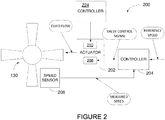
- a controller 204 receives a reference speed to which the propeller 130 is to be set.
- the controller 204 regulates fluid flow, such as oil, to the propeller 130 via an actuator 202 in accordance with the reference speed.
- a valve control signal is transmitted by the controller 204 to the actuator 202 and the actuator 202 responds by regulating fluid flow to the propeller 130 accordingly.
- One or more sensors 206 provide the controller 204 with the propeller's actual speed as measured. When the propeller's actual speed deviates from the reference speed, the controller 204 responds with a change in blade angle.
- the actuator 202 is commanded to direct fluid under pressure to the propeller 130 or to release (i.e. remove) fluid from the propeller 130. The change in fluid volume going to the propeller 130 changes the blade angle and modifies the propeller speed.
- the actuator 202 may regulate fluid flow to and from the propeller 130 via a two-position solenoid valve 208.
- the two-position solenoid valve 208 may be used as a secondary means of controlling the speed of the propeller 130 in case of failure of a primary means, such as a proportional valve 210 (also referred to as a Propeller Control Unit or PCU), which is controlled by a separate controller 224 via a separate valve control signal.
- a proportional valve 210 also referred to as a Propeller Control Unit or PCU
- PCU Propeller Control Unit
- the two-position solenoid valve 208 may be used as a primary means of propeller control.
- the two-position solenoid valve 208 can be actuated between a closed position and an open position to selectively allow or prevent fluid flow (i.e.
- the two-position solenoid valve 208 is a feathering solenoid valve, used to initiate feathering of the propeller 130. When the feathering solenoid is energized, it allows fluid to flow out of the propeller dome until the propeller 130 is completely feathered, provided the feathering solenoid is maintained energized.
- the two-position solenoid valve 210 is a separate valve independent of the feathering solenoid.
- FIG. 2 shows two separate controllers 204 and 224, it should be understood that a single controller may be used to implement the control logic or functions of controllers 204 and 224.
- the controller 204 may take any suitable form.
- the controller 204 acquires a measurement of an actual speed (N P ) of the propeller (reference 130 in Figure 1 ).
- the propeller speed may be measured by the speed sensor (reference 206 in Figure 2 ), as discussed above, and the controller 204 may accordingly receive a propeller speed signal indicative of the actual propeller speed.
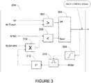
- the controller 204 uses a comparator 302 to compare the actual propeller speed to a predetermined speed threshold (N P Thresh).
- the speed threshold may be obtained by any suitable means, e.g. retrieved from a database, a memory, or other storage medium to which the controller 204 may be communicatively coupled.
- the value of the speed threshold may depend on engine configuration.
- the speed threshold is illustratively set to protect the engine (reference 110 in Figure 1 ) from overspeeding.
- the speed threshold may be set in order to protect against overspeeding when the lowest limit is reached.
- the output of the comparator 302 is set to 'TRUE' or logical one ('1') and this value is sent to the 'SET' input of a latch 304, causing the latch 304 to be set.
- a valve control signal comprising instructions to activate or energize (i.e. open) the two-position solenoid valve (reference 208 in Figure 2 ) is output.
- the two-position solenoid valve 208 is opened, it allows fluid to flow out of the propeller dome. As a result, the speed of the propeller 130 is controlled by varying the blade angles and propeller overspeed can be prevented.
- the two-position solenoid valve 208 In order to avoid overtorque, it is desirable for the two-position solenoid valve 208 to be closed as soon as the blade angle has changed and the propeller speed has decreased sufficiently to prevent overspeed.
- the controller 204 computes the rate of change of the propeller speed (N Pdot ).
- Figure 4 illustrates (for clarity purposes) that the rate of change is computed after the two-position solenoid valve 208 has been opened, it should be understood that the rate of change of propeller speed is in fact computed continuously, whether the valve is opened or closed.
- the controller 204 may comprise a derivative unit (not shown) configured to compute the derivative of the actual propeller speed, as obtained from the propeller speed signal.
- a rate of change signal indicative of the computed derivative i.e. the rate of change of propeller speed
- the controller 204 uses a comparator 306 to compare the rate of change signal to a predetermined rate of change level. When it is determined that the rate of change of propeller speed is below the predetermined rate of change level, the output of the comparator 306 is set to 'TRUE' or '1' and this value is sent to the 'RESET' input of latch 304, causing the latch 304 to be reset. When the latch 304 is reset, a valve control signal comprising instructions to de-activate or de-energize (i.e. close) the two-position solenoid valve 208 is output. When the two-position solenoid valve 208 is closed, fluid is directed into the propeller 130 to further modify the propeller speed by varying the blade angles. In this manner, precise control of propeller speed may be achieved.
- the controller 204 determines the predetermined rate of change level based on a previously stored value of the rate of change of propeller speed, the previously stored value recorded the last time the two-position solenoid valve 208 was opened.
- the predetermined rate of change level is illustratively determined by computing a given ratio of the previously stored value of the rate of change of propeller speed.
- the previous value of the rate of change of propeller speed is stored when the propeller speed reaches a value that exceeds the speed threshold.
- the output of the latch 304 is illustratively fed to a rising edge detection unit 308.
- the output of the latch 304 switches from its default value of logical zero ('0') to '1' (upon the propeller speed exceeding the speed threshold)
- the output of the rising edge flag detection unit is set to 'TRUE'.
- the previously stored value of the rate of change of propeller speed is then obtained by assigning the rate of change signal to an assigning unit 310 and computing the previous cycle of the assigned rate of change signal using a last pass unit 312.
- a multiplier 314 is then used to multiply the previously stored value of the rate of change of propeller speed, as computed and output by the last pass unit 312, with the given ratio (Npdot ratio).
- the given ratio may be a predetermined value retrieved from memory (e.g., a cache or other storage medium) and may vary depending on engine configurations. In one embodiment, the value of the ratio is determined experimentally, based on how quickly the propeller system (i.e. the propeller speed) is reacting to the opening of the feathering solenoid. The ratio may also vary as a function of other parameters, included but not limited to, altitude, temperature, and propeller speed, produced power. The selected ratio will be the ratio that ensures to reduce propeller speeds and limits undershoot.
- the output of the multiplier 314 i.e.
- the ratio of the previously stored value of the rate of change of propeller speed) is then used as the predetermined rate of change level to which the rate of change of propeller speed is compared. This in turn allows to anticipate a situation in which the propeller slows down below an acceptable threshold.
- the method 400 comprises obtaining at step 402 a measurement of an actual speed of the propeller.
- the actual speed measurement may be obtained, in real-time, from one or more sensors (e.g., speed sensor 206 in Figure 2 ).
- the next step 404 is then to assess whether the actual propeller speed as measured exceeds a predetermined speed threshold. If this is not the case, the method 400 flows back to the step 402 of obtaining propeller speed measurement. Otherwise, if it is determined that the propeller speed exceeds the predetermined speed threshold, a valve control signal is transmitted at step 406 to activate (i.e.
- step 406 also comprises recording the rate of change of propeller speed, which is referred to herein below as the previously stored value of the rate of change of propeller speed.
- the previous value of the rate of change of propeller speed is stored when it is determined (at step 404) that the propeller speed exceeds the speed threshold.
- the rate of change of propeller speed is also computed at step 408. As previously mentioned, it should be understood that the rate of change of propeller speed may be continuously calculated.
- the next step 410 is then to assess whether the rate of change of propeller speed is below a predetermined rate of change level. In one embodiment, the predetermined rate of change level is determined based on a previously stored value of the rate of change of propeller speed, as discussed above with reference to Figure 3 . If the rate of change of propeller speed is not below a predetermined rate of change level, the method 400 flows back to step 408 to continuously monitor the rate of change of propeller speed.
- a valve control signal is transmitted at step 412 to de-activate (i.e. close) the two-position solenoid valve.
- the two-position solenoid valve is closed as soon as the rate of change of propeller speed decreases below the predetermined level (i.e. before the propeller slows down below a given threshold).
- the method 400 is iterative and a continuous valve control signal is built by flowing back to step 402 after step 412 has been performed.
- the method 400 may be used to compensate for failure of a primary means of propeller speed control.
- selective actuation of the two-position solenoid valve 208 may be used to achieve a required control over fluid flow within the propeller dome, thus allowing for control of the propeller speed and for prevention of propeller overspeed.
- the systems, methods, and assemblies for propeller control described herein may be used as a secondary control means for the propeller, in the event of failure of a primary control means (e.g., in the event of mechanical failure of the proportional valve 210).
- the controller 204 of Figure 3 is implemented by means of one or more computing devices 500, as illustrated in Figure 5 .
- the computing device 500 comprises a processing unit 502 and a memory 504 which has stored therein computer-executable instructions 506.
- the processing unit 502 may comprise any suitable devices configured to implement the method 400 such that instructions 506, when executed by the computing device 500 or other programmable apparatus, may cause the functions/acts/steps performed as part of the method 400 as described herein to be executed.
- the processing unit 502 may comprise, for example, any type of general-purpose microprocessor or microcontroller, a digital signal processing (DSP) processor, a central processing unit (CPU), an integrated circuit, a field programmable gate array (FPGA), a reconfigurable processor, other suitably programmed or programmable logic circuits, or any combination thereof.
- DSP digital signal processing
- CPU central processing unit
- FPGA field programmable gate array
- reconfigurable processor other suitably programmed or programmable logic circuits, or any combination thereof.
- the memory 504 may comprise any suitable known or other machine-readable storage medium.
- the memory 504 may comprise non-transitory computer readable storage medium, for example, but not limited to, an electronic, magnetic, optical, electromagnetic, infrared, or semiconductor system, apparatus, or device, or any suitable combination of the foregoing.
- the memory 504 may include a suitable combination of any type of computer memory that is located either internally or externally to device, for example random-access memory (RAM), read-only memory (ROM), compact disc read-only memory (CDROM), electro-optical memory, magnetooptical memory, erasable programmable read-only memory (EPROM), and electrically-erasable programmable read-only memory (EEPROM), Ferroelectric RAM (FRAM) or the like.
- Memory 504 may comprise any storage means (e.g., devices) suitable for retrievably storing machine-readable instructions 506 executable by processing unit 502.
- the computing device 500 can be implemented as part of a full-authority digital engine controls (FADEC) or other similar device, including electronic engine control (EEC), engine control unit (EUC), electronic propeller control, propeller control unit, and the like.
- FADEC full-authority digital engine controls
- EEC electronic engine control
- EUC engine control unit
- propeller control propeller control unit
- the methods and systems as described herein may be implemented in a high level procedural or object oriented programming or scripting language, or a combination thereof, to communicate with or assist in the operation of a computer system, for example the computing device 8500.
- the methods and systems as described herein may be implemented in assembly or machine language.
- the language may be a compiled or interpreted language.
- Program code for implementing the methods and systems as described herein may be stored on a storage media or a device, for example a ROM, a magnetic disk, an optical disc, a flash drive, or any other suitable storage media or device.
- the program code may be readable by a general or special-purpose programmable computer for configuring and operating the computer when the storage media or device is read by the computer to perform the procedures described herein.
- Embodiments of the methods and systems as described herein may also be considered to be implemented by way of a non-transitory computer-readable storage medium having a computer program stored thereon.
- the computer program may comprise computer-readable instructions which cause a computer, or more specifically the processing unit 502 of the computing device 500, to operate in a specific and predefined manner to perform the functions described herein, for example those described in the method 400.
- Computer-executable instructions may be in many forms, including program modules, executed by one or more computers or other devices.
- program modules include routines, programs, objects, components, data structures, etc., that perform particular tasks or implement particular abstract data types.
- functionality of the program modules may be combined or distributed as desired in various embodiments.
Landscapes
- Engineering & Computer Science (AREA)
- Aviation & Aerospace Engineering (AREA)
- Chemical & Material Sciences (AREA)
- Combustion & Propulsion (AREA)
- Mechanical Engineering (AREA)
- General Engineering & Computer Science (AREA)
- Control Of Turbines (AREA)
Abstract
Description
- The present disclosure relates generally to engines, and more specifically to propeller control of aircraft engines.
- Constant speed propellers are controlled by varying blade angles to maintain the speed of the propeller at a reference speed. In order to do so, the blade angle is increased with increasing aircraft power and speed and decreased with decreasing aircraft power and speed. Varying the blade angle is achieved by either adding or removing oil in the propeller dome.
- The primary means of adding or removing oil to the propeller is through a proportional valve that controls precisely the oil flow to maintain constant speed of the propeller. A backup mode of controlling oil flow to the propeller, sometimes used when the primary mode fails, is to use an overspeed governor, which removes oil from the propeller dome proportionally to the propeller overspeed. However, use of the overspeed governor proves costly and increases the weight of the overall system.
- Therefore, improvements are needed.
- In accordance with a first aspect of the present disclosure, there is provided a method for controlling an aircraft propeller, the method comprising obtaining a measurement of a speed of the propeller, comparing the propeller speed to a first threshold, responsive to determining that the propeller speed exceeds the speed threshold, outputting a valve control signal for opening a two-position solenoid valve coupled to the propeller, the two-position solenoid valve configured for controlling fluid flow to and from the propeller to control propeller blade angle, computing a rate of change of the propeller speed, comparing the rate of change of the propeller speed to a second threshold, and responsive to determining that the rate of change of the propeller speed is below the second threshold, outputting the valve control signal for closing the two-position solenoid valve.
- In an optional embodiment, the method further comprises computing the second threshold based on a previous rate of change of propeller speed recorded upon opening of the two-position solenoid valve.
- In an optional embodiment, the second threshold is computed by multiplying the recorded rate of change with a predetermined ratio.
- In an optional embodiment, the first threshold is set at a value to prevent overspeed.
- In an optional embodiment, the valve control signal is output for controlling the two-position solenoid valve comprising a feather solenoid valve.
- In an optional embodiment, the rate of change of propeller speed is continuously computed.
- In accordance with a second aspect of the present disclosure, there is provided a system for controlling an aircraft propeller, the system comprising a processing unit and a non-transitory computer-readable storage medium having stored thereon program instructions executable by the processing unit for obtaining a measurement of a speed of the propeller, comparing the propeller speed to a first threshold, responsive to determining that the propeller speed exceeds the speed threshold, outputting a valve control signal for opening a two-position solenoid valve coupled to the propeller, the two-position solenoid valve configured for controlling fluid flow to and from the propeller to control propeller blade angle, computing a rate of change of the propeller speed, comparing the rate of change of the propeller speed to a second threshold, and responsive to determining that the rate of change of the propeller speed is below the second threshold, outputting the valve control signal for closing the two-position solenoid valve.
- In an optional embodiment, the program instructions are further executable by the processing unit for computing the second threshold based on a previous rate of change of propeller speed recorded upon opening of the two-position solenoid valve.
- In an optional embodiment, the program instructions are further executable by the processing unit for computing the second threshold by multiplying the recorded rate of change with a predetermined ratio.
- In an optional embodiment, the program instructions are further executable by the processing unit for comparing the propeller speed to the first threshold set at a value that prevents overspeed.
- In an optional embodiment, the two-position solenoid valve is a feather solenoid valve.
- In accordance with a third aspect of the present disclosure, there is provided an aircraft propeller control assembly comprising an aircraft propeller, an actuator coupled to the aircraft propeller and comprising a two-position solenoid valve for controlling fluid flow to and from the aircraft propeller to control propeller blade angle, and a controller coupled to the actuator and configured for obtaining a measurement of a speed of the propeller, comparing the propeller speed to a first threshold, responsive to determining that the propeller speed exceeds the speed threshold, outputting a valve control signal for opening the two-position solenoid valve, computing a rate of change of the propeller speed, comparing the rate of change of the propeller speed to a second threshold, and responsive to determining that the rate of change of the propeller speed is below the second threshold, outputting the valve control signal for closing the two-position solenoid valve.
- In an optional embodiment, the controller is configured for computing the second threshold based on a previous rate of change of propeller speed recorded upon opening of the two-position solenoid valve.
- In an optional embodiment, the controller is configured for computing the second threshold by multiplying the recorded rate of change with a predetermined ratio.
- In an optional embodiment, the controller is configured for comparing the propeller speed to the first threshold set at a value that prevents overspeed.
- In an optional embodiment, the two-position solenoid valve is a feather solenoid valve.
- In an optional embodiment, the controller is a secondary means of controlling the propeller and is enabled upon failure of a primary means.
- In an optional embodiment, the controller is a primary means of controlling the propeller.
- In an optional embodiment, the aircraft propeller is a single-acting propeller.
- In an optional embodiment, the aircraft propeller is a double-acting propeller.
- Features of the systems, devices, and methods described herein may be used in various combinations, in accordance with the embodiments described herein.
- Reference is now made to the accompanying figures in which:
-
Figure 1 is a schematic cross-sectional view of an engine, in accordance with one or more illustrative embodiments; -
Figure 2 is a schematic diagram of an example embodiment of a propeller control assembly; -
Figure 3 is a block diagram of a control logic embedded into a controller from the propeller control assembly ofFigure 2 , in accordance with an embodiment; -
Figure 4 is a flowchart of a method for controlling a propeller, in accordance with one embodiment; and -
Figure 5 is a block diagram of an example computing system for implementing the method ofFigure 4 , in accordance with an embodiment, in accordance with one embodiment. - It will be noted that throughout the appended drawings, like features are identified by like reference numerals.
-
Figure 1 depicts anexemplary engine 110. Theengine 110 may be any suitable aircraft propulsion system, and may include in some embodiments a hybrid-electric propulsion system or an all-electric propulsion system. The engine may be found in aircraft as well as for other industrial applications, such as for compressor drivers, ship propulsion and electric power, and locomotives. In one embodiment, theengine 110 which is a gas turbine engine of a type typically provided for use in subsonic flight. In this embodiment, theengine 110 comprises aninlet 112 through which ambient air is propelled, acompressor section 114 for pressurizing the air, acombustor 116 in which the compressed air is mixed with fuel and ignited for generating an annular stream of hot combustion gases, and aturbine section 118 for extracting energy from the combustion gases. - The
turbine section 118 comprises acompressor turbine 120, which drives the compressor assembly and accessories, and at least one power orfree turbine 122, which is independent from thecompressor turbine 120 and rotatingly drives a rotor shaft (also referred to herein as a propeller shaft or an output shaft) 124 about a propeller shaft axis 'A' through a reduction gearbox (RGB) 126. Hot gases may then be evacuated throughexhaust stubs 128. The gas generator of theengine 110 comprises thecompressor section 114, thecombustor 116, and theturbine section 118. - A rotor, in the form of a
propeller 130 through which ambient air is propelled, is hosted in apropeller hub 132. The rotor may, for example, comprise thepropeller 130 of a fixed-wing aircraft, or a main (or tail) rotor of a rotary-wing aircraft such as a helicopter. Thepropeller 130 may comprise a plurality of circumferentially-arrangedblades 134 connected to thehub 132 by any suitable means and extending radially therefrom. Theblades 134 are also each rotatable about their own radial axes through a plurality of blade angles, which can be changed to achieve modes of operation, such as feather, full reverse, and forward thrust. - The
propeller 130 converts rotary motion from theengine 110 to provide propulsive force to the aircraft.Propeller 130 is a constant speed propeller, meaning that it is designed to automatically change its blade angle (or blade pitch) to allow it to maintain a constant rotational speed, regardless of the amount of engine torque being produced, the speed of the aircraft, or the altitude at which the aircraft is flying. Other configurations for a turboprop engine may also apply. - Referring to
Figure 2 , there is illustrated an example embodiment of apropeller control assembly 200. Acontroller 204 receives a reference speed to which thepropeller 130 is to be set. Thecontroller 204 regulates fluid flow, such as oil, to thepropeller 130 via anactuator 202 in accordance with the reference speed. A valve control signal is transmitted by thecontroller 204 to theactuator 202 and theactuator 202 responds by regulating fluid flow to thepropeller 130 accordingly. - One or
more sensors 206 provide thecontroller 204 with the propeller's actual speed as measured. When the propeller's actual speed deviates from the reference speed, thecontroller 204 responds with a change in blade angle. Theactuator 202 is commanded to direct fluid under pressure to thepropeller 130 or to release (i.e. remove) fluid from thepropeller 130. The change in fluid volume going to thepropeller 130 changes the blade angle and modifies the propeller speed. - The
actuator 202 may regulate fluid flow to and from thepropeller 130 via a two-position solenoid valve 208. The two-position solenoid valve 208 may be used as a secondary means of controlling the speed of thepropeller 130 in case of failure of a primary means, such as a proportional valve 210 (also referred to as a Propeller Control Unit or PCU), which is controlled by aseparate controller 224 via a separate valve control signal. It should however be understood that, in some embodiments, the two-position solenoid valve 208 may be used as a primary means of propeller control. The two-position solenoid valve 208 can be actuated between a closed position and an open position to selectively allow or prevent fluid flow (i.e. add or remove fluid) to and from thepropeller 130. In some embodiments, the two-position solenoid valve 208 is a feathering solenoid valve, used to initiate feathering of thepropeller 130. When the feathering solenoid is energized, it allows fluid to flow out of the propeller dome until thepropeller 130 is completely feathered, provided the feathering solenoid is maintained energized. Alternatively, the two-position solenoid valve 210 is a separate valve independent of the feathering solenoid. - Although
Figure 2 shows twoseparate controllers controllers - Referring to
Figure 3 , there is illustrated an example embodiment of thecontroller 204. Thecontroller 204 may take any suitable form. In the illustrated embodiment, thecontroller 204 acquires a measurement of an actual speed (NP) of the propeller (reference 130 inFigure 1 ). The propeller speed may be measured by the speed sensor (reference 206 inFigure 2 ), as discussed above, and thecontroller 204 may accordingly receive a propeller speed signal indicative of the actual propeller speed. Thecontroller 204 then uses acomparator 302 to compare the actual propeller speed to a predetermined speed threshold (NP Thresh). The speed threshold may be obtained by any suitable means, e.g. retrieved from a database, a memory, or other storage medium to which thecontroller 204 may be communicatively coupled. The value of the speed threshold may depend on engine configuration. The speed threshold is illustratively set to protect the engine (reference 110 inFigure 1 ) from overspeeding. In one embodiment where theturbine section 118 of theengine 110 has a different overspeed limit than thepropeller 130, the speed threshold may be set in order to protect against overspeeding when the lowest limit is reached. - When it is determined that the propeller speed is above the speed threshold, the output of the
comparator 302 is set to 'TRUE' or logical one ('1') and this value is sent to the 'SET' input of alatch 304, causing thelatch 304 to be set. When thelatch 304 is set, a valve control signal comprising instructions to activate or energize (i.e. open) the two-position solenoid valve (reference 208 inFigure 2 ) is output. When the two-position solenoid valve 208 is opened, it allows fluid to flow out of the propeller dome. As a result, the speed of thepropeller 130 is controlled by varying the blade angles and propeller overspeed can be prevented. - In order to avoid overtorque, it is desirable for the two-
position solenoid valve 208 to be closed as soon as the blade angle has changed and the propeller speed has decreased sufficiently to prevent overspeed. In order to control the duration of time for the two-position solenoid valve 208 to open and ensure that the two-position solenoid valve 208 is de-activated or de-energized (i.e. closed) at the appropriate time, thecontroller 204 computes the rate of change of the propeller speed (NPdot). AlthoughFigure 4 illustrates (for clarity purposes) that the rate of change is computed after the two-position solenoid valve 208 has been opened, it should be understood that the rate of change of propeller speed is in fact computed continuously, whether the valve is opened or closed. For this purpose, thecontroller 204 may comprise a derivative unit (not shown) configured to compute the derivative of the actual propeller speed, as obtained from the propeller speed signal. A rate of change signal indicative of the computed derivative (i.e. the rate of change of propeller speed) may be output accordingly. - The
controller 204 then uses acomparator 306 to compare the rate of change signal to a predetermined rate of change level. When it is determined that the rate of change of propeller speed is below the predetermined rate of change level, the output of thecomparator 306 is set to 'TRUE' or '1' and this value is sent to the 'RESET' input oflatch 304, causing thelatch 304 to be reset. When thelatch 304 is reset, a valve control signal comprising instructions to de-activate or de-energize (i.e. close) the two-position solenoid valve 208 is output. When the two-position solenoid valve 208 is closed, fluid is directed into thepropeller 130 to further modify the propeller speed by varying the blade angles. In this manner, precise control of propeller speed may be achieved. - In one embodiment, the
controller 204 determines the predetermined rate of change level based on a previously stored value of the rate of change of propeller speed, the previously stored value recorded the last time the two-position solenoid valve 208 was opened. In particular, the predetermined rate of change level is illustratively determined by computing a given ratio of the previously stored value of the rate of change of propeller speed. In one embodiment, the previous value of the rate of change of propeller speed is stored when the propeller speed reaches a value that exceeds the speed threshold. As shown inFigure 3 , the output of thelatch 304 is illustratively fed to a risingedge detection unit 308. When the output of thelatch 304 switches from its default value of logical zero ('0') to '1' (upon the propeller speed exceeding the speed threshold), the output of the rising edge flag detection unit is set to 'TRUE'. The previously stored value of the rate of change of propeller speed is then obtained by assigning the rate of change signal to an assigningunit 310 and computing the previous cycle of the assigned rate of change signal using alast pass unit 312. Amultiplier 314 is then used to multiply the previously stored value of the rate of change of propeller speed, as computed and output by thelast pass unit 312, with the given ratio (Npdot ratio). The given ratio may be a predetermined value retrieved from memory (e.g., a cache or other storage medium) and may vary depending on engine configurations. In one embodiment, the value of the ratio is determined experimentally, based on how quickly the propeller system (i.e. the propeller speed) is reacting to the opening of the feathering solenoid. The ratio may also vary as a function of other parameters, included but not limited to, altitude, temperature, and propeller speed, produced power. The selected ratio will be the ratio that ensures to reduce propeller speeds and limits undershoot. The output of the multiplier 314 (i.e. the ratio of the previously stored value of the rate of change of propeller speed) is then used as the predetermined rate of change level to which the rate of change of propeller speed is compared. This in turn allows to anticipate a situation in which the propeller slows down below an acceptable threshold. - It should be understood that the logic for determining the predetermined rate of change level is described above with reference to
Figure 3 in accordance with one embodiment. Any other suitable logic may be used to determine the predetermined rate of change level based on a previously stored value of the rate of change of propeller speed. - Referring now to
Figure 4 , anexample method 400 for controlling a propeller, in accordance with one embodiment, will now be described. Themethod 400 comprises obtaining at step 402 a measurement of an actual speed of the propeller. The actual speed measurement may be obtained, in real-time, from one or more sensors (e.g.,speed sensor 206 inFigure 2 ). Thenext step 404 is then to assess whether the actual propeller speed as measured exceeds a predetermined speed threshold. If this is not the case, themethod 400 flows back to thestep 402 of obtaining propeller speed measurement. Otherwise, if it is determined that the propeller speed exceeds the predetermined speed threshold, a valve control signal is transmitted atstep 406 to activate (i.e. open) a two-position solenoid valve used to regulate fluid flow to and from thepropeller 130. Activation of the two-position solenoid valve results in fluid being released from the propeller system to modify the propeller speed and accordingly prevent overspeed. Although not illustrated, it should be understood thatstep 406 also comprises recording the rate of change of propeller speed, which is referred to herein below as the previously stored value of the rate of change of propeller speed. In other words, the previous value of the rate of change of propeller speed is stored when it is determined (at step 404) that the propeller speed exceeds the speed threshold. - The rate of change of propeller speed is also computed at
step 408. As previously mentioned, it should be understood that the rate of change of propeller speed may be continuously calculated. Thenext step 410 is then to assess whether the rate of change of propeller speed is below a predetermined rate of change level. In one embodiment, the predetermined rate of change level is determined based on a previously stored value of the rate of change of propeller speed, as discussed above with reference toFigure 3 . If the rate of change of propeller speed is not below a predetermined rate of change level, themethod 400 flows back to step 408 to continuously monitor the rate of change of propeller speed. Otherwise, if it is determined that the rate of change of propeller speed is below the predetermined rate of change level, a valve control signal is transmitted atstep 412 to de-activate (i.e. close) the two-position solenoid valve. In other words, the two-position solenoid valve is closed as soon as the rate of change of propeller speed decreases below the predetermined level (i.e. before the propeller slows down below a given threshold). - In some embodiments, the
method 400 is iterative and a continuous valve control signal is built by flowing back to step 402 afterstep 412 has been performed. Themethod 400 may be used to compensate for failure of a primary means of propeller speed control. - It should be understood that the systems and methods described herein may apply to single-acting propeller systems (having counterweighted blades and a feather spring that constantly pushes the blades towards feather) or double-acting propeller systems (where the propeller governor control pressure on both sides of a piston to increase or decrease pitch as required).
- From the above description, it can be seen that, in one embodiment, selective actuation of the two-
position solenoid valve 208 may be used to achieve a required control over fluid flow within the propeller dome, thus allowing for control of the propeller speed and for prevention of propeller overspeed. The systems, methods, and assemblies for propeller control described herein may be used as a secondary control means for the propeller, in the event of failure of a primary control means (e.g., in the event of mechanical failure of the proportional valve 210). - In some embodiments, the
controller 204 ofFigure 3 is implemented by means of one ormore computing devices 500, as illustrated inFigure 5 . Thecomputing device 500 comprises aprocessing unit 502 and amemory 504 which has stored therein computer-executable instructions 506. Theprocessing unit 502 may comprise any suitable devices configured to implement themethod 400 such thatinstructions 506, when executed by thecomputing device 500 or other programmable apparatus, may cause the functions/acts/steps performed as part of themethod 400 as described herein to be executed. Theprocessing unit 502 may comprise, for example, any type of general-purpose microprocessor or microcontroller, a digital signal processing (DSP) processor, a central processing unit (CPU), an integrated circuit, a field programmable gate array (FPGA), a reconfigurable processor, other suitably programmed or programmable logic circuits, or any combination thereof. - The
memory 504 may comprise any suitable known or other machine-readable storage medium. Thememory 504 may comprise non-transitory computer readable storage medium, for example, but not limited to, an electronic, magnetic, optical, electromagnetic, infrared, or semiconductor system, apparatus, or device, or any suitable combination of the foregoing. Thememory 504 may include a suitable combination of any type of computer memory that is located either internally or externally to device, for example random-access memory (RAM), read-only memory (ROM), compact disc read-only memory (CDROM), electro-optical memory, magnetooptical memory, erasable programmable read-only memory (EPROM), and electrically-erasable programmable read-only memory (EEPROM), Ferroelectric RAM (FRAM) or the like.Memory 504 may comprise any storage means (e.g., devices) suitable for retrievably storing machine-readable instructions 506 executable by processingunit 502. Note that thecomputing device 500 can be implemented as part of a full-authority digital engine controls (FADEC) or other similar device, including electronic engine control (EEC), engine control unit (EUC), electronic propeller control, propeller control unit, and the like. - The methods and systems as described herein may be implemented in a high level procedural or object oriented programming or scripting language, or a combination thereof, to communicate with or assist in the operation of a computer system, for example the computing device 8500. Alternatively, the methods and systems as described herein may be implemented in assembly or machine language. The language may be a compiled or interpreted language. Program code for implementing the methods and systems as described herein may be stored on a storage media or a device, for example a ROM, a magnetic disk, an optical disc, a flash drive, or any other suitable storage media or device. The program code may be readable by a general or special-purpose programmable computer for configuring and operating the computer when the storage media or device is read by the computer to perform the procedures described herein. Embodiments of the methods and systems as described herein may also be considered to be implemented by way of a non-transitory computer-readable storage medium having a computer program stored thereon. The computer program may comprise computer-readable instructions which cause a computer, or more specifically the
processing unit 502 of thecomputing device 500, to operate in a specific and predefined manner to perform the functions described herein, for example those described in themethod 400. - Computer-executable instructions may be in many forms, including program modules, executed by one or more computers or other devices. Generally, program modules include routines, programs, objects, components, data structures, etc., that perform particular tasks or implement particular abstract data types. Typically the functionality of the program modules may be combined or distributed as desired in various embodiments.
- The above description is meant to be exemplary only, and one skilled in the art will recognize that changes may be made to the embodiments described without departing from the scope of the invention disclosed. Still other modifications which fall within the scope of the present invention will be apparent to those skilled in the art, in light of a review of this disclosure.
- Various aspects of the systems and methods as described herein may be used alone, in combination, or in a variety of arrangements not specifically discussed in the embodiments described in the foregoing and is therefore not limited in its application to the details and arrangement of components set forth in the foregoing description or illustrated in the drawings. For example, aspects described in one embodiment may be combined in any manner with aspects described in other embodiments. Although particular embodiments have been shown and described, it will be apparent to those skilled in the art that changes and modifications may be made without departing from this invention in its broader aspects. The scope of the following claims should not be limited by the embodiments set forth in the examples, but should be given the broadest reasonable interpretation consistent with the description as a whole.
Claims (15)
- A method (400) for controlling an aircraft propeller (130), the method (400) comprising:obtaining a measurement of a speed (NP) of the propeller (130);comparing the propeller speed (NP) to a first threshold (NP Thresh);responsive to determining that the propeller speed (NP) exceeds the speed threshold (NP Thresh), outputting a valve control signal for opening a two-position solenoid valve (208) coupled to the propeller (130), the two-position solenoid valve (208) configured for controlling fluid flow to and from the propeller (130) to control propeller blade angle;computing a rate of change of the propeller speed (NPdot);comparing the rate of change of the propeller speed (NPdot) to a second threshold; andresponsive to determining that the rate of change of the propeller speed (NPdot) is below the second threshold, outputting the valve control signal for closing the two-position solenoid valve (208).
- The method of claim 1, further comprising computing the second threshold based on a previous rate of change of propeller speed recorded upon opening of the two-position solenoid valve (208), optionally wherein the second threshold is computed by multiplying the recorded rate of change with a predetermined ratio.
- The method of claim 1 or 2, wherein the first threshold (NP Thresh) is set at a value to prevent overspeed.
- The method of any preceding claim, wherein the valve control signal is output for controlling the two-position solenoid valve (208) comprising a feather solenoid valve.
- The method of any preceding claim, wherein the rate of change of propeller speed (NPdot) is continuously computed.
- A system for controlling an aircraft propeller (130), the system comprising:a processing unit (502); anda non-transitory computer-readable storage medium (504) having stored thereon program instructions (506) executable by the processing unit (502) for implementing the method (400) of claim 1
- The system of claim 6, wherein the program instructions (506) are further executable by the processing unit (502) for computing the second threshold based on a previous rate of change of propeller speed recorded upon opening of the two-position solenoid valve (208), optionally wherein the program instructions (506) are further executable by the processing unit (502) for computing the second threshold by multiplying the recorded rate of change with a predetermined ratio.
- The system of claim 6 or 7, wherein the program instructions (506) are further executable by the processing unit (502) for comparing the propeller speed (NP) to the first threshold (NP Thresh) set at a value to prevent overspeed.
- The system of any of claims 6 to 8, wherein the two-position solenoid valve (208) is a feather solenoid valve.
- An aircraft propeller control assembly (200) comprising:an aircraft propeller (130);an actuator (202) coupled to the aircraft propeller (130) and comprising a two-position solenoid valve (208) for controlling fluid flow to and from the aircraft propeller (130) to control propeller blade angle; anda controller (204) coupled to the actuator (202) and configured for:obtaining a measurement of a speed (NP) of the propeller (130);comparing the propeller speed (NP) to a first threshold (NP Thresh);responsive to determining that the propeller speed (NP) exceeds the speed threshold (NP Thresh), outputting a valve control signal for opening the two-position solenoid valve (208);computing a rate of change of the propeller speed (NPdot);comparing the rate of change of the propeller speed (NPdot) to a second threshold; andresponsive to determining that the rate of change of the propeller speed (NPdot) is below the second threshold, outputting the valve control signal for closing the two-position solenoid valve (208).
- The assembly of claim 10, wherein the controller (204) is configured for computing the second threshold based on a previous rate of change of propeller speed recorded upon opening of the two-position solenoid valve (208), optionally wherein the controller (204) is configured for computing the second threshold by multiplying the recorded rate of change with a predetermined ratio.
- The assembly of claim 10 or 11, wherein the controller (204) is configured for comparing the propeller speed (NP) to the first threshold (NP Thresh) set at a value to prevent overspeed.
- The assembly of any of claims 10 to 12, wherein the two-position solenoid valve (208) is a feather solenoid valve.
- The assembly of any of claims 10 to 13, wherein the controller (204) is a secondary means of controlling the propeller (130) and is enabled upon failure of a primary means or the controller (204) is a primary means of controlling the propeller (130).
- The assembly of any of claims 10 to 14, wherein the aircraft propeller (130) is a single-acting propeller or a double-acting propeller.
Applications Claiming Priority (1)
| Application Number | Priority Date | Filing Date | Title |
|---|---|---|---|
| US16/418,467 US11059567B2 (en) | 2019-05-21 | 2019-05-21 | Method of controlling a propeller with two-position solenoid |
Publications (2)
| Publication Number | Publication Date |
|---|---|
| EP3741666A1 true EP3741666A1 (en) | 2020-11-25 |
| EP3741666B1 EP3741666B1 (en) | 2022-04-20 |
Family
ID=70802751
Family Applications (1)
| Application Number | Title | Priority Date | Filing Date |
|---|---|---|---|
| EP20175920.6A Active EP3741666B1 (en) | 2019-05-21 | 2020-05-21 | Method of controlling a propeller with two-position solenoid |
Country Status (4)
| Country | Link |
|---|---|
| US (1) | US11059567B2 (en) |
| EP (1) | EP3741666B1 (en) |
| CA (1) | CA3080290A1 (en) |
| PL (1) | PL3741666T3 (en) |
Cited By (2)
| Publication number | Priority date | Publication date | Assignee | Title |
|---|---|---|---|---|
| EP4035997A1 (en) * | 2021-02-01 | 2022-08-03 | Pratt & Whitney Canada Corp. | Propeller control unit validation |
| EP4082897A1 (en) * | 2021-04-27 | 2022-11-02 | Pratt & Whitney Canada Corp. | System and method for detecting and mitigating a propeller failure condition |
Families Citing this family (6)
| Publication number | Priority date | Publication date | Assignee | Title |
|---|---|---|---|---|
| US11852083B2 (en) | 2018-11-23 | 2023-12-26 | Pratt & Whitney Canada Corp. | Engine and propeller control system |
| US11408357B2 (en) * | 2018-11-23 | 2022-08-09 | Pratt & Whitney Canada Corp. | Engine and propeller control system |
| US11554851B2 (en) * | 2019-02-15 | 2023-01-17 | Pratt & Whitney Canada Corp. | System and method for aircraft propeller governing |
| FR3107925B1 (en) * | 2020-03-05 | 2022-02-11 | Safran Aircraft Engines | Servo-control of blade pitch |
| US12466545B2 (en) * | 2022-11-08 | 2025-11-11 | Pratt & Whitney Canada Corp. | Systems and methods for controlling propeller control unit fluid pressure |
| US12296941B2 (en) * | 2023-05-12 | 2025-05-13 | Pratt & Whitney Canada Corp. | System and method for controlling a propulsor for a hybrid-electric aircraft propulsion system |
Citations (7)
| Publication number | Priority date | Publication date | Assignee | Title |
|---|---|---|---|---|
| US5019006A (en) * | 1990-02-26 | 1991-05-28 | Schneider Roy W | Aircraft engine propeller overspeed protection technical field |
| US5174718A (en) * | 1991-08-12 | 1992-12-29 | United Technologies Corporation | Blade pitch change control system |
| US5299911A (en) * | 1991-07-25 | 1994-04-05 | Toyota Jidosha Kabushiki Kaisha | Electric pitch control apparatus for variable-pitch propeller |
| US5997250A (en) * | 1997-01-09 | 1999-12-07 | Catercopters, Llc | Method and apparatus for controlling pitch of an aircraft propeller |
| US6422816B1 (en) * | 2001-05-21 | 2002-07-23 | Hamilton Sundstrand Corporation | Variable pitch propeller control system |
| FR2985284A1 (en) * | 2012-01-03 | 2013-07-05 | Snecma | Device for controlling pitch of blades of non-ducted propeller of turbojet of aircraft, has flow reduction unit to limit flow of fluid leaving chambers under effect of displacement of piston in event of interruption of supply of fluid |
| EP3434585A1 (en) * | 2017-07-28 | 2019-01-30 | General Electric Company | Propeller control system for an aircraft |
Family Cites Families (7)
| Publication number | Priority date | Publication date | Assignee | Title |
|---|---|---|---|---|
| US2669312A (en) * | 1949-05-24 | 1954-02-16 | Gen Motors Corp | Aircraft propeller speed controller |
| US2754921A (en) * | 1951-10-26 | 1956-07-17 | Gen Motors Corp | Propeller control |
| US2857007A (en) * | 1954-01-06 | 1958-10-21 | Gen Motors Corp | Fluid pressure control system for variable pitch propellers |
| US4993919A (en) | 1989-04-11 | 1991-02-19 | United Technologies Corporation | Discrete (on-off) feather signal to govern propeller overspeed |
| US5037271A (en) | 1989-12-26 | 1991-08-06 | United Technologies Corporation | Pitch control system |
| US10392099B2 (en) * | 2017-05-18 | 2019-08-27 | Pratt & Whitney Canada Corp. | System and method for aircraft propeller control |
| US11554851B2 (en) * | 2019-02-15 | 2023-01-17 | Pratt & Whitney Canada Corp. | System and method for aircraft propeller governing |
-
2019
- 2019-05-21 US US16/418,467 patent/US11059567B2/en active Active
-
2020
- 2020-04-28 CA CA3080290A patent/CA3080290A1/en active Pending
- 2020-05-21 PL PL20175920.6T patent/PL3741666T3/en unknown
- 2020-05-21 EP EP20175920.6A patent/EP3741666B1/en active Active
Patent Citations (7)
| Publication number | Priority date | Publication date | Assignee | Title |
|---|---|---|---|---|
| US5019006A (en) * | 1990-02-26 | 1991-05-28 | Schneider Roy W | Aircraft engine propeller overspeed protection technical field |
| US5299911A (en) * | 1991-07-25 | 1994-04-05 | Toyota Jidosha Kabushiki Kaisha | Electric pitch control apparatus for variable-pitch propeller |
| US5174718A (en) * | 1991-08-12 | 1992-12-29 | United Technologies Corporation | Blade pitch change control system |
| US5997250A (en) * | 1997-01-09 | 1999-12-07 | Catercopters, Llc | Method and apparatus for controlling pitch of an aircraft propeller |
| US6422816B1 (en) * | 2001-05-21 | 2002-07-23 | Hamilton Sundstrand Corporation | Variable pitch propeller control system |
| FR2985284A1 (en) * | 2012-01-03 | 2013-07-05 | Snecma | Device for controlling pitch of blades of non-ducted propeller of turbojet of aircraft, has flow reduction unit to limit flow of fluid leaving chambers under effect of displacement of piston in event of interruption of supply of fluid |
| EP3434585A1 (en) * | 2017-07-28 | 2019-01-30 | General Electric Company | Propeller control system for an aircraft |
Cited By (4)
| Publication number | Priority date | Publication date | Assignee | Title |
|---|---|---|---|---|
| EP4035997A1 (en) * | 2021-02-01 | 2022-08-03 | Pratt & Whitney Canada Corp. | Propeller control unit validation |
| US11702943B2 (en) | 2021-02-01 | 2023-07-18 | Pratt & Whitney Canada Corp. | Propeller control unit validation |
| EP4082897A1 (en) * | 2021-04-27 | 2022-11-02 | Pratt & Whitney Canada Corp. | System and method for detecting and mitigating a propeller failure condition |
| US12077279B2 (en) | 2021-04-27 | 2024-09-03 | Pratt & Whitney Canada Corp. | System and method for detecting and mitigating a propeller failure condition |
Also Published As
| Publication number | Publication date |
|---|---|
| US20200369370A1 (en) | 2020-11-26 |
| PL3741666T3 (en) | 2022-08-29 |
| US11059567B2 (en) | 2021-07-13 |
| CA3080290A1 (en) | 2020-11-21 |
| EP3741666B1 (en) | 2022-04-20 |
Similar Documents
| Publication | Publication Date | Title |
|---|---|---|
| EP3741666B1 (en) | Method of controlling a propeller with two-position solenoid | |
| US11299286B2 (en) | System and method for operating a multi-engine aircraft | |
| US11408357B2 (en) | Engine and propeller control system | |
| EP3594110B1 (en) | System and method for feathering an aircraft propeller | |
| US11313286B2 (en) | Integrated propeller and engine controller | |
| US10823113B2 (en) | Method and system for limiting power of an engine | |
| US11668253B2 (en) | System and method for providing in-flight reverse thrust for an aircraft | |
| US12077279B2 (en) | System and method for detecting and mitigating a propeller failure condition | |
| CN111924127B (en) | System and method for detecting uncommanded or uncontrollable high thrust events in an aircraft | |
| US11852083B2 (en) | Engine and propeller control system | |
| US11554851B2 (en) | System and method for aircraft propeller governing | |
| US11136134B2 (en) | System and method for operating a gas turbine engine coupled to an aircraft propeller | |
| EP3705398B1 (en) | Method and system for operating an engine in a multi-engine aircraft | |
| CA3060755A1 (en) | Integrated propeller and engine controller | |
| CA3052432A1 (en) | Method and system for adjusting a variable geometry mechanism | |
| CA3079168A1 (en) | Method and system for operating an aircraft powerplant |
Legal Events
| Date | Code | Title | Description |
|---|---|---|---|
| PUAI | Public reference made under article 153(3) epc to a published international application that has entered the european phase |
Free format text: ORIGINAL CODE: 0009012 |
|
| STAA | Information on the status of an ep patent application or granted ep patent |
Free format text: STATUS: THE APPLICATION HAS BEEN PUBLISHED |
|
| AK | Designated contracting states |
Kind code of ref document: A1 Designated state(s): AL AT BE BG CH CY CZ DE DK EE ES FI FR GB GR HR HU IE IS IT LI LT LU LV MC MK MT NL NO PL PT RO RS SE SI SK SM TR |
|
| AX | Request for extension of the european patent |
Extension state: BA ME |
|
| STAA | Information on the status of an ep patent application or granted ep patent |
Free format text: STATUS: REQUEST FOR EXAMINATION WAS MADE |
|
| 17P | Request for examination filed |
Effective date: 20210525 |
|
| RBV | Designated contracting states (corrected) |
Designated state(s): AL AT BE BG CH CY CZ DE DK EE ES FI FR GB GR HR HU IE IS IT LI LT LU LV MC MK MT NL NO PL PT RO RS SE SI SK SM TR |
|
| GRAP | Despatch of communication of intention to grant a patent |
Free format text: ORIGINAL CODE: EPIDOSNIGR1 |
|
| STAA | Information on the status of an ep patent application or granted ep patent |
Free format text: STATUS: GRANT OF PATENT IS INTENDED |
|
| RIC1 | Information provided on ipc code assigned before grant |
Ipc: F02C 9/58 20060101ALN20211012BHEP Ipc: B64C 11/40 20060101ALI20211012BHEP Ipc: B64C 11/42 20060101ALI20211012BHEP Ipc: B64C 11/38 20060101ALI20211012BHEP Ipc: B64C 11/30 20060101AFI20211012BHEP |
|
| INTG | Intention to grant announced |
Effective date: 20211103 |
|
| GRAS | Grant fee paid |
Free format text: ORIGINAL CODE: EPIDOSNIGR3 |
|
| GRAA | (expected) grant |
Free format text: ORIGINAL CODE: 0009210 |
|
| STAA | Information on the status of an ep patent application or granted ep patent |
Free format text: STATUS: THE PATENT HAS BEEN GRANTED |
|
| AK | Designated contracting states |
Kind code of ref document: B1 Designated state(s): AL AT BE BG CH CY CZ DE DK EE ES FI FR GB GR HR HU IE IS IT LI LT LU LV MC MK MT NL NO PL PT RO RS SE SI SK SM TR |
|
| REG | Reference to a national code |
Ref country code: GB Ref legal event code: FG4D |
|
| REG | Reference to a national code |
Ref country code: CH Ref legal event code: EP |
|
| REG | Reference to a national code |
Ref country code: IE Ref legal event code: FG4D |
|
| REG | Reference to a national code |
Ref country code: DE Ref legal event code: R096 Ref document number: 602020002723 Country of ref document: DE |
|
| REG | Reference to a national code |
Ref country code: AT Ref legal event code: REF Ref document number: 1484989 Country of ref document: AT Kind code of ref document: T Effective date: 20220515 |
|
| REG | Reference to a national code |
Ref country code: LT Ref legal event code: MG9D |
|
| REG | Reference to a national code |
Ref country code: NL Ref legal event code: MP Effective date: 20220420 |
|
| REG | Reference to a national code |
Ref country code: AT Ref legal event code: MK05 Ref document number: 1484989 Country of ref document: AT Kind code of ref document: T Effective date: 20220420 |
|
| PG25 | Lapsed in a contracting state [announced via postgrant information from national office to epo] |
Ref country code: NL Free format text: LAPSE BECAUSE OF FAILURE TO SUBMIT A TRANSLATION OF THE DESCRIPTION OR TO PAY THE FEE WITHIN THE PRESCRIBED TIME-LIMIT Effective date: 20220420 |
|
| PG25 | Lapsed in a contracting state [announced via postgrant information from national office to epo] |
Ref country code: SE Free format text: LAPSE BECAUSE OF FAILURE TO SUBMIT A TRANSLATION OF THE DESCRIPTION OR TO PAY THE FEE WITHIN THE PRESCRIBED TIME-LIMIT Effective date: 20220420 Ref country code: PT Free format text: LAPSE BECAUSE OF FAILURE TO SUBMIT A TRANSLATION OF THE DESCRIPTION OR TO PAY THE FEE WITHIN THE PRESCRIBED TIME-LIMIT Effective date: 20220822 Ref country code: NO Free format text: LAPSE BECAUSE OF FAILURE TO SUBMIT A TRANSLATION OF THE DESCRIPTION OR TO PAY THE FEE WITHIN THE PRESCRIBED TIME-LIMIT Effective date: 20220720 Ref country code: LT Free format text: LAPSE BECAUSE OF FAILURE TO SUBMIT A TRANSLATION OF THE DESCRIPTION OR TO PAY THE FEE WITHIN THE PRESCRIBED TIME-LIMIT Effective date: 20220420 Ref country code: HR Free format text: LAPSE BECAUSE OF FAILURE TO SUBMIT A TRANSLATION OF THE DESCRIPTION OR TO PAY THE FEE WITHIN THE PRESCRIBED TIME-LIMIT Effective date: 20220420 Ref country code: GR Free format text: LAPSE BECAUSE OF FAILURE TO SUBMIT A TRANSLATION OF THE DESCRIPTION OR TO PAY THE FEE WITHIN THE PRESCRIBED TIME-LIMIT Effective date: 20220721 Ref country code: FI Free format text: LAPSE BECAUSE OF FAILURE TO SUBMIT A TRANSLATION OF THE DESCRIPTION OR TO PAY THE FEE WITHIN THE PRESCRIBED TIME-LIMIT Effective date: 20220420 Ref country code: ES Free format text: LAPSE BECAUSE OF FAILURE TO SUBMIT A TRANSLATION OF THE DESCRIPTION OR TO PAY THE FEE WITHIN THE PRESCRIBED TIME-LIMIT Effective date: 20220420 Ref country code: BG Free format text: LAPSE BECAUSE OF FAILURE TO SUBMIT A TRANSLATION OF THE DESCRIPTION OR TO PAY THE FEE WITHIN THE PRESCRIBED TIME-LIMIT Effective date: 20220720 Ref country code: AT Free format text: LAPSE BECAUSE OF FAILURE TO SUBMIT A TRANSLATION OF THE DESCRIPTION OR TO PAY THE FEE WITHIN THE PRESCRIBED TIME-LIMIT Effective date: 20220420 |
|
| PG25 | Lapsed in a contracting state [announced via postgrant information from national office to epo] |
Ref country code: RS Free format text: LAPSE BECAUSE OF FAILURE TO SUBMIT A TRANSLATION OF THE DESCRIPTION OR TO PAY THE FEE WITHIN THE PRESCRIBED TIME-LIMIT Effective date: 20220420 Ref country code: LV Free format text: LAPSE BECAUSE OF FAILURE TO SUBMIT A TRANSLATION OF THE DESCRIPTION OR TO PAY THE FEE WITHIN THE PRESCRIBED TIME-LIMIT Effective date: 20220420 Ref country code: IS Free format text: LAPSE BECAUSE OF FAILURE TO SUBMIT A TRANSLATION OF THE DESCRIPTION OR TO PAY THE FEE WITHIN THE PRESCRIBED TIME-LIMIT Effective date: 20220820 |
|
| REG | Reference to a national code |
Ref country code: DE Ref legal event code: R097 Ref document number: 602020002723 Country of ref document: DE |
|
| REG | Reference to a national code |
Ref country code: BE Ref legal event code: MM Effective date: 20220531 |
|
| PG25 | Lapsed in a contracting state [announced via postgrant information from national office to epo] |
Ref country code: SM Free format text: LAPSE BECAUSE OF FAILURE TO SUBMIT A TRANSLATION OF THE DESCRIPTION OR TO PAY THE FEE WITHIN THE PRESCRIBED TIME-LIMIT Effective date: 20220420 Ref country code: SK Free format text: LAPSE BECAUSE OF FAILURE TO SUBMIT A TRANSLATION OF THE DESCRIPTION OR TO PAY THE FEE WITHIN THE PRESCRIBED TIME-LIMIT Effective date: 20220420 Ref country code: RO Free format text: LAPSE BECAUSE OF FAILURE TO SUBMIT A TRANSLATION OF THE DESCRIPTION OR TO PAY THE FEE WITHIN THE PRESCRIBED TIME-LIMIT Effective date: 20220420 Ref country code: MC Free format text: LAPSE BECAUSE OF FAILURE TO SUBMIT A TRANSLATION OF THE DESCRIPTION OR TO PAY THE FEE WITHIN THE PRESCRIBED TIME-LIMIT Effective date: 20220420 Ref country code: LU Free format text: LAPSE BECAUSE OF NON-PAYMENT OF DUE FEES Effective date: 20220521 Ref country code: EE Free format text: LAPSE BECAUSE OF FAILURE TO SUBMIT A TRANSLATION OF THE DESCRIPTION OR TO PAY THE FEE WITHIN THE PRESCRIBED TIME-LIMIT Effective date: 20220420 Ref country code: DK Free format text: LAPSE BECAUSE OF FAILURE TO SUBMIT A TRANSLATION OF THE DESCRIPTION OR TO PAY THE FEE WITHIN THE PRESCRIBED TIME-LIMIT Effective date: 20220420 |
|
| PLBE | No opposition filed within time limit |
Free format text: ORIGINAL CODE: 0009261 |
|
| STAA | Information on the status of an ep patent application or granted ep patent |
Free format text: STATUS: NO OPPOSITION FILED WITHIN TIME LIMIT |
|
| 26N | No opposition filed |
Effective date: 20230123 |
|
| PG25 | Lapsed in a contracting state [announced via postgrant information from national office to epo] |
Ref country code: AL Free format text: LAPSE BECAUSE OF FAILURE TO SUBMIT A TRANSLATION OF THE DESCRIPTION OR TO PAY THE FEE WITHIN THE PRESCRIBED TIME-LIMIT Effective date: 20220420 |
|
| PG25 | Lapsed in a contracting state [announced via postgrant information from national office to epo] |
Ref country code: IE Free format text: LAPSE BECAUSE OF NON-PAYMENT OF DUE FEES Effective date: 20220521 |
|
| PG25 | Lapsed in a contracting state [announced via postgrant information from national office to epo] |
Ref country code: SI Free format text: LAPSE BECAUSE OF FAILURE TO SUBMIT A TRANSLATION OF THE DESCRIPTION OR TO PAY THE FEE WITHIN THE PRESCRIBED TIME-LIMIT Effective date: 20220420 Ref country code: BE Free format text: LAPSE BECAUSE OF NON-PAYMENT OF DUE FEES Effective date: 20220531 |
|
| P01 | Opt-out of the competence of the unified patent court (upc) registered |
Effective date: 20230530 |
|
| REG | Reference to a national code |
Ref country code: CH Ref legal event code: PL |
|
| PG25 | Lapsed in a contracting state [announced via postgrant information from national office to epo] |
Ref country code: LI Free format text: LAPSE BECAUSE OF NON-PAYMENT OF DUE FEES Effective date: 20230531 Ref country code: IT Free format text: LAPSE BECAUSE OF FAILURE TO SUBMIT A TRANSLATION OF THE DESCRIPTION OR TO PAY THE FEE WITHIN THE PRESCRIBED TIME-LIMIT Effective date: 20220420 Ref country code: CH Free format text: LAPSE BECAUSE OF NON-PAYMENT OF DUE FEES Effective date: 20230531 |
|
| PG25 | Lapsed in a contracting state [announced via postgrant information from national office to epo] |
Ref country code: MK Free format text: LAPSE BECAUSE OF FAILURE TO SUBMIT A TRANSLATION OF THE DESCRIPTION OR TO PAY THE FEE WITHIN THE PRESCRIBED TIME-LIMIT Effective date: 20220420 Ref country code: CY Free format text: LAPSE BECAUSE OF FAILURE TO SUBMIT A TRANSLATION OF THE DESCRIPTION OR TO PAY THE FEE WITHIN THE PRESCRIBED TIME-LIMIT Effective date: 20220420 |
|
| PG25 | Lapsed in a contracting state [announced via postgrant information from national office to epo] |
Ref country code: HU Free format text: LAPSE BECAUSE OF FAILURE TO SUBMIT A TRANSLATION OF THE DESCRIPTION OR TO PAY THE FEE WITHIN THE PRESCRIBED TIME-LIMIT; INVALID AB INITIO Effective date: 20200521 |
|
| PG25 | Lapsed in a contracting state [announced via postgrant information from national office to epo] |
Ref country code: MT Free format text: LAPSE BECAUSE OF FAILURE TO SUBMIT A TRANSLATION OF THE DESCRIPTION OR TO PAY THE FEE WITHIN THE PRESCRIBED TIME-LIMIT Effective date: 20220420 |
|
| PG25 | Lapsed in a contracting state [announced via postgrant information from national office to epo] |
Ref country code: BG Free format text: LAPSE BECAUSE OF FAILURE TO SUBMIT A TRANSLATION OF THE DESCRIPTION OR TO PAY THE FEE WITHIN THE PRESCRIBED TIME-LIMIT Effective date: 20220420 |
|
| PG25 | Lapsed in a contracting state [announced via postgrant information from national office to epo] |
Ref country code: BG Free format text: LAPSE BECAUSE OF FAILURE TO SUBMIT A TRANSLATION OF THE DESCRIPTION OR TO PAY THE FEE WITHIN THE PRESCRIBED TIME-LIMIT Effective date: 20220420 |
|
| PGFP | Annual fee paid to national office [announced via postgrant information from national office to epo] |
Ref country code: PL Payment date: 20250424 Year of fee payment: 6 Ref country code: DE Payment date: 20250423 Year of fee payment: 6 |
|
| PGFP | Annual fee paid to national office [announced via postgrant information from national office to epo] |
Ref country code: GB Payment date: 20250423 Year of fee payment: 6 |
|
| PGFP | Annual fee paid to national office [announced via postgrant information from national office to epo] |
Ref country code: FR Payment date: 20250423 Year of fee payment: 6 |
|
| PGFP | Annual fee paid to national office [announced via postgrant information from national office to epo] |
Ref country code: CZ Payment date: 20250429 Year of fee payment: 6 |
|
| PG25 | Lapsed in a contracting state [announced via postgrant information from national office to epo] |
Ref country code: TR Free format text: LAPSE BECAUSE OF FAILURE TO SUBMIT A TRANSLATION OF THE DESCRIPTION OR TO PAY THE FEE WITHIN THE PRESCRIBED TIME-LIMIT Effective date: 20220420 |