EP3741614B1 - Slide-out room mechanism with rack and pinion drive - Google Patents
Slide-out room mechanism with rack and pinion drive Download PDFInfo
- Publication number
- EP3741614B1 EP3741614B1 EP19196246.3A EP19196246A EP3741614B1 EP 3741614 B1 EP3741614 B1 EP 3741614B1 EP 19196246 A EP19196246 A EP 19196246A EP 3741614 B1 EP3741614 B1 EP 3741614B1
- Authority
- EP
- European Patent Office
- Prior art keywords
- slide
- out room
- drive
- gear
- drive mechanism
- Prior art date
- Legal status (The legal status is an assumption and is not a legal conclusion. Google has not performed a legal analysis and makes no representation as to the accuracy of the status listed.)
- Not-in-force
Links
- 230000007246 mechanism Effects 0.000 title claims description 29
- 230000007704 transition Effects 0.000 description 2
- 230000000712 assembly Effects 0.000 description 1
- 238000000429 assembly Methods 0.000 description 1
- 238000010276 construction Methods 0.000 description 1
- 238000007789 sealing Methods 0.000 description 1
- 230000001360 synchronised effect Effects 0.000 description 1
Images


Classifications
-
- B—PERFORMING OPERATIONS; TRANSPORTING
- B60—VEHICLES IN GENERAL
- B60P—VEHICLES ADAPTED FOR LOAD TRANSPORTATION OR TO TRANSPORT, TO CARRY, OR TO COMPRISE SPECIAL LOADS OR OBJECTS
- B60P3/00—Vehicles adapted to transport, to carry or to comprise special loads or objects
- B60P3/32—Vehicles adapted to transport, to carry or to comprise special loads or objects comprising living accommodation for people, e.g. caravans, camping, or like vehicles
-
- B—PERFORMING OPERATIONS; TRANSPORTING
- B60—VEHICLES IN GENERAL
- B60P—VEHICLES ADAPTED FOR LOAD TRANSPORTATION OR TO TRANSPORT, TO CARRY, OR TO COMPRISE SPECIAL LOADS OR OBJECTS
- B60P3/00—Vehicles adapted to transport, to carry or to comprise special loads or objects
- B60P3/32—Vehicles adapted to transport, to carry or to comprise special loads or objects comprising living accommodation for people, e.g. caravans, camping, or like vehicles
- B60P3/34—Vehicles adapted to transport, to carry or to comprise special loads or objects comprising living accommodation for people, e.g. caravans, camping, or like vehicles the living accommodation being expansible, collapsible or capable of rearrangement
-
- F—MECHANICAL ENGINEERING; LIGHTING; HEATING; WEAPONS; BLASTING
- F16—ENGINEERING ELEMENTS AND UNITS; GENERAL MEASURES FOR PRODUCING AND MAINTAINING EFFECTIVE FUNCTIONING OF MACHINES OR INSTALLATIONS; THERMAL INSULATION IN GENERAL
- F16H—GEARING
- F16H19/00—Gearings comprising essentially only toothed gears or friction members and not capable of conveying indefinitely-continuing rotary motion
- F16H19/02—Gearings comprising essentially only toothed gears or friction members and not capable of conveying indefinitely-continuing rotary motion for interconverting rotary or oscillating motion and reciprocating motion
- F16H19/04—Gearings comprising essentially only toothed gears or friction members and not capable of conveying indefinitely-continuing rotary motion for interconverting rotary or oscillating motion and reciprocating motion comprising a rack
Definitions
- the invention relates to a slide-out or retractable room for mobile living quarters, such as a recreational vehicle.
- a retractable or slide-out room for increasing the living space of the vehicle.
- the retractable or slide-out room is extended for use when the vehicle is parked and is retracted into the main living area of the vehicle when the vehicle is in transit.
- Slide-out rooms typically require substantial space for mounting large electrical motors and hydraulic units that require the construction of expensive covers and thus reduce the overall space inside the vehicle.
- US2015/0040700A1 relates to a drive mechanism for a slide-out room of a recreational vehicle, and more particularly, to a manual override for such a drive mechanism.
- the drive system for the slide- out room may utilize a rack and pinion drive system to eliminate use of the conventional drive screw.
- Actuating mechanisms may be installed on opposite side walls of the slide- out room and the adjoining portions of the wall of the main living area through which the slide-out room extends and retracts.
- Each of the actuating assemblies include a pair of pinion gears mounted on a rotatable torque shaft/drive shaft, which are supported for rotation in the main living quarters adjacent the opening in the wall of the main living quarters through which the slide-out room extends and retracts.
- the two pinion gears are meshed with the teeth of corresponding gear racks, which are mounted on the adjacent sidewall of the slide-out room.
- the gear racks may be covered with respective cover members through which the pinion gears extend to engage the racks.
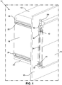
- FIG. 1 is a perspective view of a slide-out room system 10 for a vehicle.
- the system 10 includes a room defined by a top wall 12, a floor 14 and a pair of sidewalls 16 connected between the top wall 12 and the floor 14.
- the slide-out room is shown in an extended or expanded position.
- the slide-out room extends through an opening in a wall W typically in the side of the vehicle.
- the view in FIG. 1 shows an interior of the vehicle wall W.
- First or upper corner brackets 18 are provided at an intersection of each of the sidewalls 16 and the top wall 12
- second or lower corner brackets 20 are provided at an intersection of each of the sidewalls 16 and the bottom wall 14.
- the corner brackets 18, 20 provide a rounded transition between the top wall 12 and the sidewalls 16 and between the bottom wall 14 and the sidewalls 16, respectively.
- a first or upper horizontal gear rack 22 is secured on the sidewall 16 via a channel 24 in the corner bracket 18 (see FIG. 4 ).
- a second or lower horizontal gear rack 26 is spaced from the first horizontal gear rack 22 and is secured on the sidewall 16 via a similar channel in the lower corner bracket 20.
- a motor 28 is fixed to the wall W via a motor bracket 30 and anchor brackets 32.
- the motor 28 is thus fixed to the wall W relative to the slide-out room adjacent the sidewall 16.
- a fluted motor shaft or drive shaft 34 is coupled with the motor 28 for rotation by the motor.
- the drive shaft 34 extends through a correspondingly shaped opening in a first drive gear 36 that engages the first horizontal gear rack 22.
- the drive shaft 34 also extends through a second drive gear 38 engaging the second horizontal gear rack 26.
- a gear housing 40 is fixed to the wall W of the vehicle adjacent the sidewall 16 of the slide-out room.
- the gear housing 40 includes a first compartment 42 in which the first drive gear 36 is disposed.
- a second gear housing 44 similarly includes a compartment in which the second drive gear 38 is disposed.
- the gear housings 40, 44 include a hole 46 therethrough, where the drive shaft 34 is positioned through the holes 46 in the first and second gear housings and through the first 36 and second 38 drive gears.
- a slider 48 may be secured to each of the first gear housing 40 and the second gear housing 44.
- the sliders 48 respectively engage exterior surfaces of the first 22 and second 26 horizontal gear racks.
- the sliders 48 may be formed in multiple pieces.
- the drive gears 36, 38 are positioned through an opening in each of the sliders 48, respectively.
- a cover 50 is secured in suitable channels of the corner brackets 18, 20 and is positioned over each of the first horizontal gear rack 22 and the second horizontal gear rack 26.
- the covers 50 conceal the gear racks 22, 26.
- the drive gears 36, 38 extend through the covers 50 into engagement with the first and second horizontal gear racks 22, 26, respectively.
- the covers 50 cover the entire lengths of the respective horizontal gear racks 22, 26.
- FIG. 5 is an exploded view showing the components of the slide-out room system.
- a narrow frame member 52 is secured in the opening in the vehicle wall W, and a seal member such as a V-shaped seal or "V seal” 54 is positioned between the narrow frame 52 and the slide-out room. Since the frame 52 and seal 54 are fixed in the vehicle opening, the slide-out room is displaceable relative to the seal 54, and the slide-out room remains sealed in the retracted position, the extended position and while transitioning between the retracted and extended positions.
- electric motors 28 are connected to drive gears 36, 38 that engage the first and second gear racks 22, 26 respectively, driving movement of the slide- out room. This movement may be distributed or synchronized with the lower portion of the room with the first drive gear 36 engaged with the first gear rack 22 and the second drive gear 38 engaged with the second gear rack 26.
- the drive shaft 34 may not be directly connected to the motor 28 such that the drive shaft 34 acts solely as a secondary synchronization mechanism between the top and bottom of the room.
- An equalizing or synchronizing assembly that transfers some of the force/movement delivered to the lower portion of the slide-out room to the upper portion of the room is described in U.S. Patent No. 9,221,378 .
Landscapes
- Engineering & Computer Science (AREA)
- Mechanical Engineering (AREA)
- Health & Medical Sciences (AREA)
- Public Health (AREA)
- Transportation (AREA)
- General Engineering & Computer Science (AREA)
- Transmission Devices (AREA)
- Power-Operated Mechanisms For Wings (AREA)
Description
- The invention relates to a slide-out or retractable room for mobile living quarters, such as a recreational vehicle.
- Recreational vehicles, such as motor homes, fifth-wheel trailers, and travel trailers may be provided with a retractable or slide-out room for increasing the living space of the vehicle. The retractable or slide-out room is extended for use when the vehicle is parked and is retracted into the main living area of the vehicle when the vehicle is in transit. Slide-out rooms typically require substantial space for mounting large electrical motors and hydraulic units that require the construction of expensive covers and thus reduce the overall space inside the vehicle.
- Existing mechanisms for extending and retracting slide-out rooms utilize a drive screw that is designed to stay in tension. When improperly constructed, the screw can compress, which causes the screw to bow and contact the housing. Additionally, it is typical for the motor on the screw drive to move with the room, which also requires the wires to move.
- Other problems with existing systems include undesirably exposed operating components when the room is expanded as well as inadequate sealing during transition between retracted and expanded positions.
-
US2015/0040700A1 relates to a drive mechanism for a slide-out room of a recreational vehicle, and more particularly, to a manual override for such a drive mechanism. - It would thus be desirable for a slide-out room system that overcomes the shortcomings of existing systems. This is achieved with a drive mechanism according to independent claim 1. In some embodiments, the drive system for the slide- out room may utilize a rack and pinion drive system to eliminate use of the conventional drive screw. Actuating mechanisms may be installed on opposite side walls of the slide- out room and the adjoining portions of the wall of the main living area through which the slide-out room extends and retracts. Each of the actuating assemblies include a pair of pinion gears mounted on a rotatable torque shaft/drive shaft, which are supported for rotation in the main living quarters adjacent the opening in the wall of the main living quarters through which the slide-out room extends and retracts. The two pinion gears are meshed with the teeth of corresponding gear racks, which are mounted on the adjacent sidewall of the slide-out room. The gear racks may be covered with respective cover members through which the pinion gears extend to engage the racks.
- These and other aspects and advantages will be described in detail with reference to the accompanying drawings, in which:
-
FIG. 1 is a perspective view showing the drive mechanism and slide-out room with the slide-out room in an extended position; -
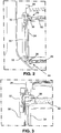
FIG. 2 shows components of the drive mechanism with the slide-out room in a retracted position; -
FIG. 3 shows one corner of the slide-out room and the components of the drive mechanism; -
FIG. 4 is a sectional view through one corner of the drive mechanism components; -
FIG. 5 is an exploded view of the slide-out room system; -
FIG. 6 is an exploded view of an upper corner showing the drive mechanism components; and -
FIG. 7 is an exploded view showing a lower corner of the drive mechanism components. -
FIG. 1 is a perspective view of a slide-outroom system 10 for a vehicle. Thesystem 10 includes a room defined by atop wall 12, afloor 14 and a pair ofsidewalls 16 connected between thetop wall 12 and thefloor 14. InFIG. 1 , the slide-out room is shown in an extended or expanded position. The slide-out room extends through an opening in a wall W typically in the side of the vehicle. The view inFIG. 1 shows an interior of the vehicle wall W. - Components of the drive mechanism will be described with reference to the
side wall 16 shown inFIG. 1 , it being understood that identical components for the drive mechanism are associated with the opposite sidewall. - First or
upper corner brackets 18 are provided at an intersection of each of thesidewalls 16 and thetop wall 12, and second orlower corner brackets 20 are provided at an intersection of each of thesidewalls 16 and thebottom wall 14. In some embodiments, thecorner brackets top wall 12 and thesidewalls 16 and between thebottom wall 14 and thesidewalls 16, respectively. - A first or upper
horizontal gear rack 22 is secured on thesidewall 16 via achannel 24 in the corner bracket 18 (seeFIG. 4 ). A second or lowerhorizontal gear rack 26 is spaced from the firsthorizontal gear rack 22 and is secured on thesidewall 16 via a similar channel in thelower corner bracket 20. - Inside the vehicle on an interior of the vehicle wall W, a
motor 28 is fixed to the wall W via amotor bracket 30 andanchor brackets 32. Themotor 28 is thus fixed to the wall W relative to the slide-out room adjacent thesidewall 16. A fluted motor shaft ordrive shaft 34 is coupled with themotor 28 for rotation by the motor. - The
drive shaft 34 extends through a correspondingly shaped opening in afirst drive gear 36 that engages the firsthorizontal gear rack 22. Thedrive shaft 34 also extends through asecond drive gear 38 engaging the secondhorizontal gear rack 26. - A
gear housing 40 is fixed to the wall W of the vehicle adjacent thesidewall 16 of the slide-out room. Thegear housing 40 includes afirst compartment 42 in which thefirst drive gear 36 is disposed. A second gear housing 44 (seeFIGS. 1 and2 ) similarly includes a compartment in which thesecond drive gear 38 is disposed. As shown inFigs. 5-7 , thegear housings hole 46 therethrough, where thedrive shaft 34 is positioned through theholes 46 in the first and second gear housings and through the first 36 and second 38 drive gears. - With continued reference to
FIG. 4 , aslider 48 may be secured to each of thefirst gear housing 40 and thesecond gear housing 44. Thesliders 48 respectively engage exterior surfaces of the first 22 and second 26 horizontal gear racks. As shown inFigs. 6 and7 , thesliders 48 may be formed in multiple pieces. Thedrive gears sliders 48, respectively. - A
cover 50 is secured in suitable channels of thecorner brackets horizontal gear rack 22 and the secondhorizontal gear rack 26. The covers 50 conceal the gear racks 22, 26. As shown inFIG. 4 , thedrive gears covers 50 into engagement with the first and secondhorizontal gear racks covers 50 cover the entire lengths of the respective horizontal gear racks 22, 26. -
FIG. 5 is an exploded view showing the components of the slide-out room system. Anarrow frame member 52 is secured in the opening in the vehicle wall W, and a seal member such as a V-shaped seal or "V seal" 54 is positioned between thenarrow frame 52 and the slide-out room. Since theframe 52 andseal 54 are fixed in the vehicle opening, the slide-out room is displaceable relative to theseal 54, and the slide-out room remains sealed in the retracted position, the extended position and while transitioning between the retracted and extended positions. - As described,
electric motors 28 are connected to drivegears first drive gear 36 engaged with thefirst gear rack 22 and thesecond drive gear 38 engaged with thesecond gear rack 26. In some embodiments, thedrive shaft 34 may not be directly connected to themotor 28 such that thedrive shaft 34 acts solely as a secondary synchronization mechanism between the top and bottom of the room. An equalizing or synchronizing assembly that transfers some of the force/movement delivered to the lower portion of the slide-out room to the upper portion of the room is described inU.S. Patent No. 9,221,378 - The use of a rack and pinion drive eliminates problems with existing systems utilizing a drive screw. Another advantage is the use of two motors rather than four motors. A drive shaft connects two sets of gearing for each of the two motors.
Moreover, the motors are fixed relative to the slide-out room and thus do not move with the room, resulting in a simplified and more reliable assembly.
Claims (12)
- A drive mechanism for a slide-out room, the drive mechanism comprising:a first horizontal gear rack (22) secured on a sidewall (16) of the slide-out room;a second horizontal gear rack (26) spaced from the first horizontal gear rack (22) and secured on the sidewall (16) of the slide-out room;a motor (28) fixed relative to the slide-out room adjacent the sidewall (16) of the slide-out room;a drive shaft (34) coupled with the motor (28);a first drive gear (36) coupled with the drive shaft (34) and engaging the first horizontal gear rack (22);a second drive gear (38) coupled with the drive shaft (34) and engaging the second horizontal gear rack (26);characterized in that the drive mechanism further comprisesa first cover (50) positioned over and concealing the first horizontal gear rack (22); anda second cover positioned over and concealing the second horizontal gear rack (26),wherein the first drive gear (36) extends through the first cover (50) into engagement with the first horizontal gear rack (22), and wherein the second drive gear (38) extends through the second cover into engagement with the second horizontal gear rack (26).
- A drive mechanism according to claim 1, further comprising a first gear housing (40) fixed relative to the slide-out room adjacent the sidewall (16) of the slide- out room and a second gear housing (44) fixed relative to the slide-out room adjacent the sidewall (16) of the slide-out room, the first gear housing (40) including a first compartment (42), and the second gear housing (44) including a second compartment, wherein the first drive gear (36) is disposed in the first compartment (42), and the second drive gear (38) is disposed in the second compartment.
- A drive mechanism according to claim 2, wherein the first and second gear housings (40, 44) include a hole (46) therethough, and wherein the drive shaft (34) is positioned through the holes (46) in the first (40) and second (44) gear housings and through the first (36) and second (38) drive gears.
- A drive mechanism according to claim 2, further comprising a slider (48) secured to each of the first gear housing (40) and the second gear housing (44), the sliders (48) respectively engaging exterior surfaces of the first (22) and second (26) horizontal gear racks.
- A drive mechanism according to claim 4, wherein the first (36) and second (38) drive gears are positioned through an opening in each of the sliders (48), respectively.
- A drive mechanism according to claim 1, further comprising a slider (48) engaging exterior surfaces of each of the first (22) and second (26) horizontal gear racks.
- A drive mechanism according to claim 6, wherein the first (22) and second (26) drive gears are positioned through an opening in each of the sliders (48), respectively.
- A drive mechanism according to claim 1, wherein the first cover and the second cover (50) are secured in respective corner brackets (18, 20) of the slide-out room.
- A slide-out room system for a vehicle, the slide-out room system comprising:a first drive mechanism according any preceding claim;a second drive mechanism according to any preceding claim; anda room defined by a top wall (12), a floor (14), the side wall (16) of the first drive mechanism and the side wall (16) of the second drive mechanism, the pair of sidewalls (16) connected between the top wall (12) and the floor (14).
- A slide-out room system according to claim 9, wherein the room includes first corner brackets (18) at an intersection of each of the sidewalls (16) with the top wall (12) and second corner brackets (20) at an intersection of each of the sidewalls (16) with the bottom wall (14), the first corner brackets (18) comprising a first channel (24) respectively housing the first horizontal gear racks (22), and the second corner brackets (20) comprising a second channel respectively housing the second horizontal gear racks (26).
- A slide-out room system according to claim 10, wherein the first covers (50) are secured in the first corner brackets (18) adjacent the first horizontal gear racks (22), and wherein the second covers are secured in the second corner brackets (20) adjacent the second horizontal gear racks (26).
- A slide-out room system according to claim 10, wherein the first corner brackets (18) and the second corner brackets (20) are rounded.
Priority Applications (1)
| Application Number | Priority Date | Filing Date | Title |
|---|---|---|---|
| SI201930153T SI3741614T1 (en) | 2019-05-20 | 2019-09-09 | Slide-out room mechanism with rack and pinion drive |
Applications Claiming Priority (1)
| Application Number | Priority Date | Filing Date | Title |
|---|---|---|---|
| IT102019000007030A IT201900007030A1 (en) | 2019-05-20 | 2019-05-20 | SLIDING MECHANISM OF A REMOVABLE ROOM WITH PINION AND RACK OPERATION |
Publications (2)
| Publication Number | Publication Date |
|---|---|
| EP3741614A1 EP3741614A1 (en) | 2020-11-25 |
| EP3741614B1 true EP3741614B1 (en) | 2021-11-03 |
Family
ID=67734772
Family Applications (1)
| Application Number | Title | Priority Date | Filing Date |
|---|---|---|---|
| EP19196246.3A Not-in-force EP3741614B1 (en) | 2019-05-20 | 2019-09-09 | Slide-out room mechanism with rack and pinion drive |
Country Status (8)
| Country | Link |
|---|---|
| US (2) | US11124107B2 (en) |
| EP (1) | EP3741614B1 (en) |
| CN (1) | CN111959380A (en) |
| AU (1) | AU2019205986B1 (en) |
| ES (1) | ES2903267T3 (en) |
| HU (1) | HUE057515T2 (en) |
| IT (1) | IT201900007030A1 (en) |
| SI (1) | SI3741614T1 (en) |
Families Citing this family (3)
| Publication number | Priority date | Publication date | Assignee | Title |
|---|---|---|---|---|
| US10927929B2 (en) * | 2019-02-05 | 2021-02-23 | David H. Vroom | Preventing torque-caused impair of a sliding support mechanism |
| CN113939117B (en) * | 2020-06-29 | 2023-06-02 | 戴尔产品有限公司 | Gear train side latch mechanism for modular information handling resources |
| CN114851939B (en) * | 2022-07-07 | 2022-11-11 | 成都苏试广博环境可靠性技术有限公司 | Generator discharging device based on shelter car |
Family Cites Families (16)
| Publication number | Priority date | Publication date | Assignee | Title |
|---|---|---|---|---|
| US6981728B2 (en) | 1999-11-23 | 2006-01-03 | Happijac Company | Sliding mechanisms and systems |
| US6428073B1 (en) * | 2000-11-27 | 2002-08-06 | Rbw Industries, Inc. | Vehicle with slide-out room |
| US7374218B2 (en) | 2004-03-23 | 2008-05-20 | Lippert Components, Inc. | Slide-out member with embedded gear rack for use in slide-out room mechanisms |
| US7588279B2 (en) | 2005-05-31 | 2009-09-15 | Lippert Components, Inc. | Slide-out mechanisms and systems |
| US8016343B2 (en) | 2009-01-21 | 2011-09-13 | Lippert Components Manufacturing, Inc. | Retractable room actuation assembly for recreational vehicle |
| US8573666B2 (en) * | 2009-01-21 | 2013-11-05 | Lippert Components Manufacturing | Retractable room actuation assembly for recreational vehicle |
| CN201566551U (en) * | 2009-12-29 | 2010-09-01 | 北京三兴汽车有限公司 | Vehicular extensible square cabin body |
| EP2343214B1 (en) * | 2010-01-06 | 2016-01-27 | Lippert Components Manufacturing, Inc. | Retractable room actuation assembly for recreational vehicle |
| US8840164B2 (en) | 2011-10-26 | 2014-09-23 | Lippert Components Manufacturing, Inc. | Slide-out room system having wall-mounted drive mechanisms |
| US8991890B2 (en) | 2011-10-26 | 2015-03-31 | Lippert Components Manufacturing, Inc. | Slide-out room system having wall-mounted drive mechanisms |
| US9221378B2 (en) | 2012-11-20 | 2015-12-29 | AL-KO Kober A.G. | Slide-out room mechanism for a vehicle |
| US9050923B1 (en) * | 2013-03-14 | 2015-06-09 | Norco Industries, Inc. | Slidable room assembly |
| ES2784678T3 (en) * | 2013-08-06 | 2020-09-29 | Lippert Components Mfg Inc | Manual control for sliding cabin system that has a wall-mounted drive mechanism |
| JP6749995B2 (en) * | 2015-03-31 | 2020-09-02 | エックスエル・アイピー・ベー・フェー | Slide out room and operating mechanism and their components |
| CN208665040U (en) * | 2018-08-15 | 2019-03-29 | 杭州恒宏机械有限公司 | A kind of caravan expansion structure component |
| US10480627B1 (en) * | 2019-02-05 | 2019-11-19 | David H. Vroom | Sliding support mechanism with improved reliability and serviceability |
-
2019
- 2019-05-20 IT IT102019000007030A patent/IT201900007030A1/en unknown
- 2019-07-15 AU AU2019205986A patent/AU2019205986B1/en not_active Ceased
- 2019-07-22 CN CN201910662032.0A patent/CN111959380A/en active Pending
- 2019-08-01 US US16/528,786 patent/US11124107B2/en not_active Expired - Fee Related
- 2019-09-09 HU HUE19196246A patent/HUE057515T2/en unknown
- 2019-09-09 EP EP19196246.3A patent/EP3741614B1/en not_active Not-in-force
- 2019-09-09 SI SI201930153T patent/SI3741614T1/en unknown
- 2019-09-09 ES ES19196246T patent/ES2903267T3/en active Active
-
2021
- 2021-08-20 US US17/408,020 patent/US20210380031A1/en not_active Abandoned
Also Published As
| Publication number | Publication date |
|---|---|
| US11124107B2 (en) | 2021-09-21 |
| US20210380031A1 (en) | 2021-12-09 |
| US20200369193A1 (en) | 2020-11-26 |
| AU2019205986B1 (en) | 2020-09-03 |
| EP3741614A1 (en) | 2020-11-25 |
| ES2903267T3 (en) | 2022-03-31 |
| HUE057515T2 (en) | 2022-06-28 |
| SI3741614T1 (en) | 2022-04-29 |
| IT201900007030A1 (en) | 2020-11-20 |
| CN111959380A (en) | 2020-11-20 |
Similar Documents
| Publication | Publication Date | Title |
|---|---|---|
| EP3741614B1 (en) | Slide-out room mechanism with rack and pinion drive | |
| EP3030456B1 (en) | Manual override for slide-out room system having wall-mounted drive mechanism | |
| US10471878B2 (en) | Retractable room actuation assembly for recreational vehicle | |
| US7891730B2 (en) | Drive unit for at least two movable parts of a vehicle, in particular a roof assembly thereof | |
| US9446703B1 (en) | Slidable room assembly | |
| US6681531B2 (en) | Twin motor drive for a slide-out room | |
| US8573666B2 (en) | Retractable room actuation assembly for recreational vehicle | |
| EP3277539B2 (en) | Slide-out room and operating mechanism and components thereof | |
| JPS63227416A (en) | Roof for automobile having cover on roof opening section | |
| US10525866B2 (en) | Slide-out room and operating mechanism and components thereof | |
| US11072272B2 (en) | Movable wall structure for a travel trailer | |
| EP2782786A1 (en) | Flip device for vehicle-mounted equipment and vehicle having the same | |
| JP2010132128A (en) | On-vehicle image display device | |
| AU2019208210C1 (en) | Slide-out mechanism with a fixed spindle drive | |
| EP3741615B1 (en) | Slide-out room mechanism with cable drive | |
| WO2017035068A1 (en) | Slide-out room for van |
Legal Events
| Date | Code | Title | Description |
|---|---|---|---|
| PUAI | Public reference made under article 153(3) epc to a published international application that has entered the european phase |
Free format text: ORIGINAL CODE: 0009012 |
|
| STAA | Information on the status of an ep patent application or granted ep patent |
Free format text: STATUS: THE APPLICATION HAS BEEN PUBLISHED |
|
| AK | Designated contracting states |
Kind code of ref document: A1 Designated state(s): AL AT BE BG CH CY CZ DE DK EE ES FI FR GB GR HR HU IE IS IT LI LT LU LV MC MK MT NL NO PL PT RO RS SE SI SK SM TR |
|
| AX | Request for extension of the european patent |
Extension state: BA ME |
|
| STAA | Information on the status of an ep patent application or granted ep patent |
Free format text: STATUS: REQUEST FOR EXAMINATION WAS MADE |
|
| 17P | Request for examination filed |
Effective date: 20201203 |
|
| RBV | Designated contracting states (corrected) |
Designated state(s): AL AT BE BG CH CY CZ DE DK EE ES FI FR GB GR HR HU IE IS IT LI LT LU LV MC MK MT NL NO PL PT RO RS SE SI SK SM TR |
|
| GRAP | Despatch of communication of intention to grant a patent |
Free format text: ORIGINAL CODE: EPIDOSNIGR1 |
|
| STAA | Information on the status of an ep patent application or granted ep patent |
Free format text: STATUS: GRANT OF PATENT IS INTENDED |
|
| INTG | Intention to grant announced |
Effective date: 20210506 |
|
| GRAS | Grant fee paid |
Free format text: ORIGINAL CODE: EPIDOSNIGR3 |
|
| GRAA | (expected) grant |
Free format text: ORIGINAL CODE: 0009210 |
|
| STAA | Information on the status of an ep patent application or granted ep patent |
Free format text: STATUS: THE PATENT HAS BEEN GRANTED |
|
| AK | Designated contracting states |
Kind code of ref document: B1 Designated state(s): AL AT BE BG CH CY CZ DE DK EE ES FI FR GB GR HR HU IE IS IT LI LT LU LV MC MK MT NL NO PL PT RO RS SE SI SK SM TR |
|
| REG | Reference to a national code |
Ref country code: GB Ref legal event code: FG4D |
|
| REG | Reference to a national code |
Ref country code: AT Ref legal event code: REF Ref document number: 1443675 Country of ref document: AT Kind code of ref document: T Effective date: 20211115 Ref country code: CH Ref legal event code: EP |
|
| REG | Reference to a national code |
Ref country code: DE Ref legal event code: R096 Ref document number: 602019008894 Country of ref document: DE |
|
| REG | Reference to a national code |
Ref country code: IE Ref legal event code: FG4D |
|
| REG | Reference to a national code |
Ref country code: SE Ref legal event code: TRGR |
|
| REG | Reference to a national code |
Ref country code: NL Ref legal event code: FP |
|
| REG | Reference to a national code |
Ref country code: LT Ref legal event code: MG9D |
|
| REG | Reference to a national code |
Ref country code: AT Ref legal event code: MK05 Ref document number: 1443675 Country of ref document: AT Kind code of ref document: T Effective date: 20211103 |
|
| REG | Reference to a national code |
Ref country code: ES Ref legal event code: FG2A Ref document number: 2903267 Country of ref document: ES Kind code of ref document: T3 Effective date: 20220331 |
|
| PG25 | Lapsed in a contracting state [announced via postgrant information from national office to epo] |
Ref country code: RS Free format text: LAPSE BECAUSE OF FAILURE TO SUBMIT A TRANSLATION OF THE DESCRIPTION OR TO PAY THE FEE WITHIN THE PRESCRIBED TIME-LIMIT Effective date: 20211103 Ref country code: LT Free format text: LAPSE BECAUSE OF FAILURE TO SUBMIT A TRANSLATION OF THE DESCRIPTION OR TO PAY THE FEE WITHIN THE PRESCRIBED TIME-LIMIT Effective date: 20211103 Ref country code: FI Free format text: LAPSE BECAUSE OF FAILURE TO SUBMIT A TRANSLATION OF THE DESCRIPTION OR TO PAY THE FEE WITHIN THE PRESCRIBED TIME-LIMIT Effective date: 20211103 Ref country code: BG Free format text: LAPSE BECAUSE OF FAILURE TO SUBMIT A TRANSLATION OF THE DESCRIPTION OR TO PAY THE FEE WITHIN THE PRESCRIBED TIME-LIMIT Effective date: 20220203 Ref country code: AT Free format text: LAPSE BECAUSE OF FAILURE TO SUBMIT A TRANSLATION OF THE DESCRIPTION OR TO PAY THE FEE WITHIN THE PRESCRIBED TIME-LIMIT Effective date: 20211103 |
|
| PG25 | Lapsed in a contracting state [announced via postgrant information from national office to epo] |
Ref country code: IS Free format text: LAPSE BECAUSE OF FAILURE TO SUBMIT A TRANSLATION OF THE DESCRIPTION OR TO PAY THE FEE WITHIN THE PRESCRIBED TIME-LIMIT Effective date: 20220303 Ref country code: PT Free format text: LAPSE BECAUSE OF FAILURE TO SUBMIT A TRANSLATION OF THE DESCRIPTION OR TO PAY THE FEE WITHIN THE PRESCRIBED TIME-LIMIT Effective date: 20220303 Ref country code: PL Free format text: LAPSE BECAUSE OF FAILURE TO SUBMIT A TRANSLATION OF THE DESCRIPTION OR TO PAY THE FEE WITHIN THE PRESCRIBED TIME-LIMIT Effective date: 20211103 Ref country code: NO Free format text: LAPSE BECAUSE OF FAILURE TO SUBMIT A TRANSLATION OF THE DESCRIPTION OR TO PAY THE FEE WITHIN THE PRESCRIBED TIME-LIMIT Effective date: 20220203 Ref country code: LV Free format text: LAPSE BECAUSE OF FAILURE TO SUBMIT A TRANSLATION OF THE DESCRIPTION OR TO PAY THE FEE WITHIN THE PRESCRIBED TIME-LIMIT Effective date: 20211103 Ref country code: HR Free format text: LAPSE BECAUSE OF FAILURE TO SUBMIT A TRANSLATION OF THE DESCRIPTION OR TO PAY THE FEE WITHIN THE PRESCRIBED TIME-LIMIT Effective date: 20211103 Ref country code: GR Free format text: LAPSE BECAUSE OF FAILURE TO SUBMIT A TRANSLATION OF THE DESCRIPTION OR TO PAY THE FEE WITHIN THE PRESCRIBED TIME-LIMIT Effective date: 20220204 |
|
| REG | Reference to a national code |
Ref country code: HU Ref legal event code: AG4A Ref document number: E057515 Country of ref document: HU |
|
| PG25 | Lapsed in a contracting state [announced via postgrant information from national office to epo] |
Ref country code: SM Free format text: LAPSE BECAUSE OF FAILURE TO SUBMIT A TRANSLATION OF THE DESCRIPTION OR TO PAY THE FEE WITHIN THE PRESCRIBED TIME-LIMIT Effective date: 20211103 Ref country code: SK Free format text: LAPSE BECAUSE OF FAILURE TO SUBMIT A TRANSLATION OF THE DESCRIPTION OR TO PAY THE FEE WITHIN THE PRESCRIBED TIME-LIMIT Effective date: 20211103 Ref country code: RO Free format text: LAPSE BECAUSE OF FAILURE TO SUBMIT A TRANSLATION OF THE DESCRIPTION OR TO PAY THE FEE WITHIN THE PRESCRIBED TIME-LIMIT Effective date: 20211103 Ref country code: EE Free format text: LAPSE BECAUSE OF FAILURE TO SUBMIT A TRANSLATION OF THE DESCRIPTION OR TO PAY THE FEE WITHIN THE PRESCRIBED TIME-LIMIT Effective date: 20211103 Ref country code: DK Free format text: LAPSE BECAUSE OF FAILURE TO SUBMIT A TRANSLATION OF THE DESCRIPTION OR TO PAY THE FEE WITHIN THE PRESCRIBED TIME-LIMIT Effective date: 20211103 Ref country code: CZ Free format text: LAPSE BECAUSE OF FAILURE TO SUBMIT A TRANSLATION OF THE DESCRIPTION OR TO PAY THE FEE WITHIN THE PRESCRIBED TIME-LIMIT Effective date: 20211103 |
|
| REG | Reference to a national code |
Ref country code: DE Ref legal event code: R097 Ref document number: 602019008894 Country of ref document: DE |
|
| PLBE | No opposition filed within time limit |
Free format text: ORIGINAL CODE: 0009261 |
|
| STAA | Information on the status of an ep patent application or granted ep patent |
Free format text: STATUS: NO OPPOSITION FILED WITHIN TIME LIMIT |
|
| 26N | No opposition filed |
Effective date: 20220804 |
|
| PG25 | Lapsed in a contracting state [announced via postgrant information from national office to epo] |
Ref country code: AL Free format text: LAPSE BECAUSE OF FAILURE TO SUBMIT A TRANSLATION OF THE DESCRIPTION OR TO PAY THE FEE WITHIN THE PRESCRIBED TIME-LIMIT Effective date: 20211103 |
|
| PGFP | Annual fee paid to national office [announced via postgrant information from national office to epo] |
Ref country code: SE Payment date: 20220927 Year of fee payment: 4 Ref country code: NL Payment date: 20220926 Year of fee payment: 4 Ref country code: DE Payment date: 20220928 Year of fee payment: 4 |
|
| PGFP | Annual fee paid to national office [announced via postgrant information from national office to epo] |
Ref country code: SI Payment date: 20220819 Year of fee payment: 4 Ref country code: HU Payment date: 20220821 Year of fee payment: 4 Ref country code: FR Payment date: 20220926 Year of fee payment: 4 |
|
| PGFP | Annual fee paid to national office [announced via postgrant information from national office to epo] |
Ref country code: IT Payment date: 20220930 Year of fee payment: 4 Ref country code: ES Payment date: 20221003 Year of fee payment: 4 |
|
| PG25 | Lapsed in a contracting state [announced via postgrant information from national office to epo] |
Ref country code: MC Free format text: LAPSE BECAUSE OF FAILURE TO SUBMIT A TRANSLATION OF THE DESCRIPTION OR TO PAY THE FEE WITHIN THE PRESCRIBED TIME-LIMIT Effective date: 20211103 |
|
| REG | Reference to a national code |
Ref country code: CH Ref legal event code: PL |
|
| REG | Reference to a national code |
Ref country code: BE Ref legal event code: MM Effective date: 20220930 |
|
| PG25 | Lapsed in a contracting state [announced via postgrant information from national office to epo] |
Ref country code: LU Free format text: LAPSE BECAUSE OF NON-PAYMENT OF DUE FEES Effective date: 20220909 |
|
| P01 | Opt-out of the competence of the unified patent court (upc) registered |
Effective date: 20230530 |
|
| PG25 | Lapsed in a contracting state [announced via postgrant information from national office to epo] |
Ref country code: LI Free format text: LAPSE BECAUSE OF NON-PAYMENT OF DUE FEES Effective date: 20220930 Ref country code: IE Free format text: LAPSE BECAUSE OF NON-PAYMENT OF DUE FEES Effective date: 20220909 Ref country code: CH Free format text: LAPSE BECAUSE OF NON-PAYMENT OF DUE FEES Effective date: 20220930 |
|
| PG25 | Lapsed in a contracting state [announced via postgrant information from national office to epo] |
Ref country code: BE Free format text: LAPSE BECAUSE OF NON-PAYMENT OF DUE FEES Effective date: 20220930 |
|
| REG | Reference to a national code |
Ref country code: DE Ref legal event code: R119 Ref document number: 602019008894 Country of ref document: DE |
|
| PG25 | Lapsed in a contracting state [announced via postgrant information from national office to epo] |
Ref country code: CY Free format text: LAPSE BECAUSE OF FAILURE TO SUBMIT A TRANSLATION OF THE DESCRIPTION OR TO PAY THE FEE WITHIN THE PRESCRIBED TIME-LIMIT Effective date: 20211103 |
|
| REG | Reference to a national code |
Ref country code: SE Ref legal event code: EUG |
|
| REG | Reference to a national code |
Ref country code: NL Ref legal event code: MM Effective date: 20231001 |
|
| GBPC | Gb: european patent ceased through non-payment of renewal fee |
Effective date: 20230909 |
|
| PG25 | Lapsed in a contracting state [announced via postgrant information from national office to epo] |
Ref country code: MK Free format text: LAPSE BECAUSE OF FAILURE TO SUBMIT A TRANSLATION OF THE DESCRIPTION OR TO PAY THE FEE WITHIN THE PRESCRIBED TIME-LIMIT Effective date: 20211103 |
|
| PG25 | Lapsed in a contracting state [announced via postgrant information from national office to epo] |
Ref country code: NL Free format text: LAPSE BECAUSE OF NON-PAYMENT OF DUE FEES Effective date: 20231001 |
|
| PG25 | Lapsed in a contracting state [announced via postgrant information from national office to epo] |
Ref country code: TR Free format text: LAPSE BECAUSE OF FAILURE TO SUBMIT A TRANSLATION OF THE DESCRIPTION OR TO PAY THE FEE WITHIN THE PRESCRIBED TIME-LIMIT Effective date: 20211103 Ref country code: NL Free format text: LAPSE BECAUSE OF NON-PAYMENT OF DUE FEES Effective date: 20231001 |
|
| PG25 | Lapsed in a contracting state [announced via postgrant information from national office to epo] |
Ref country code: GB Free format text: LAPSE BECAUSE OF NON-PAYMENT OF DUE FEES Effective date: 20230909 |
|
| PG25 | Lapsed in a contracting state [announced via postgrant information from national office to epo] |
Ref country code: GB Free format text: LAPSE BECAUSE OF NON-PAYMENT OF DUE FEES Effective date: 20230909 Ref country code: FR Free format text: LAPSE BECAUSE OF NON-PAYMENT OF DUE FEES Effective date: 20230930 Ref country code: DE Free format text: LAPSE BECAUSE OF NON-PAYMENT OF DUE FEES Effective date: 20240403 Ref country code: SI Free format text: LAPSE BECAUSE OF NON-PAYMENT OF DUE FEES Effective date: 20230910 |
|
| PG25 | Lapsed in a contracting state [announced via postgrant information from national office to epo] |
Ref country code: SE Free format text: LAPSE BECAUSE OF NON-PAYMENT OF DUE FEES Effective date: 20230910 Ref country code: HU Free format text: LAPSE BECAUSE OF NON-PAYMENT OF DUE FEES Effective date: 20230910 |
|
| REG | Reference to a national code |
Ref country code: SI Ref legal event code: KO00 Effective date: 20240715 |
|
| PG25 | Lapsed in a contracting state [announced via postgrant information from national office to epo] |
Ref country code: MT Free format text: LAPSE BECAUSE OF FAILURE TO SUBMIT A TRANSLATION OF THE DESCRIPTION OR TO PAY THE FEE WITHIN THE PRESCRIBED TIME-LIMIT Effective date: 20211103 |
|
| REG | Reference to a national code |
Ref country code: ES Ref legal event code: FD2A Effective date: 20241025 |
|
| PG25 | Lapsed in a contracting state [announced via postgrant information from national office to epo] |
Ref country code: IT Free format text: LAPSE BECAUSE OF NON-PAYMENT OF DUE FEES Effective date: 20230909 |
|
| PG25 | Lapsed in a contracting state [announced via postgrant information from national office to epo] |
Ref country code: IT Free format text: LAPSE BECAUSE OF NON-PAYMENT OF DUE FEES Effective date: 20230909 |
|
| PG25 | Lapsed in a contracting state [announced via postgrant information from national office to epo] |
Ref country code: ES Free format text: LAPSE BECAUSE OF NON-PAYMENT OF DUE FEES Effective date: 20230910 |
|
| PG25 | Lapsed in a contracting state [announced via postgrant information from national office to epo] |
Ref country code: ES Free format text: LAPSE BECAUSE OF NON-PAYMENT OF DUE FEES Effective date: 20230910 |